EP4235731A1 - Measurement and correction of optical aberrations in charged particle beam microscopy - Google Patents
Measurement and correction of optical aberrations in charged particle beam microscopy Download PDFInfo
- Publication number
- EP4235731A1 EP4235731A1 EP23158474.9A EP23158474A EP4235731A1 EP 4235731 A1 EP4235731 A1 EP 4235731A1 EP 23158474 A EP23158474 A EP 23158474A EP 4235731 A1 EP4235731 A1 EP 4235731A1
- Authority
- EP
- European Patent Office
- Prior art keywords
- charged particle
- images
- optical
- particle beam
- pattern
- Prior art date
- Legal status (The legal status is an assumption and is not a legal conclusion. Google has not performed a legal analysis and makes no representation as to the accuracy of the status listed.)
- Pending
Links
- 230000004075 alteration Effects 0.000 title claims abstract description 263
- 230000003287 optical effect Effects 0.000 title claims abstract description 221
- 239000002245 particle Substances 0.000 title claims abstract description 151
- 238000012937 correction Methods 0.000 title claims description 42
- 238000005259 measurement Methods 0.000 title description 6
- 238000000386 microscopy Methods 0.000 title 1
- 238000003384 imaging method Methods 0.000 claims abstract description 22
- 230000005540 biological transmission Effects 0.000 claims abstract description 13
- 238000000034 method Methods 0.000 claims description 83
- 201000009310 astigmatism Diseases 0.000 claims description 48
- 206010010071 Coma Diseases 0.000 claims description 24
- 230000000737 periodic effect Effects 0.000 claims description 18
- 230000033001 locomotion Effects 0.000 claims description 8
- 238000012545 processing Methods 0.000 description 14
- 238000010586 diagram Methods 0.000 description 12
- 238000012544 monitoring process Methods 0.000 description 11
- 238000004891 communication Methods 0.000 description 9
- 238000013528 artificial neural network Methods 0.000 description 7
- 230000000875 corresponding effect Effects 0.000 description 6
- 230000008569 process Effects 0.000 description 4
- 230000008859 change Effects 0.000 description 3
- 238000005457 optimization Methods 0.000 description 3
- 238000010894 electron beam technology Methods 0.000 description 2
- 230000003993 interaction Effects 0.000 description 2
- 238000001228 spectrum Methods 0.000 description 2
- 238000004627 transmission electron microscopy Methods 0.000 description 2
- 230000001133 acceleration Effects 0.000 description 1
- 238000009825 accumulation Methods 0.000 description 1
- 238000004364 calculation method Methods 0.000 description 1
- 230000000295 complement effect Effects 0.000 description 1
- 238000004590 computer program Methods 0.000 description 1
- 230000002596 correlated effect Effects 0.000 description 1
- 230000001419 dependent effect Effects 0.000 description 1
- 238000001514 detection method Methods 0.000 description 1
- 230000000694 effects Effects 0.000 description 1
- 230000006870 function Effects 0.000 description 1
- 238000005286 illumination Methods 0.000 description 1
- 238000011835 investigation Methods 0.000 description 1
- 238000002955 isolation Methods 0.000 description 1
- 239000000463 material Substances 0.000 description 1
- 230000007246 mechanism Effects 0.000 description 1
- 238000003062 neural network model Methods 0.000 description 1
- 230000001151 other effect Effects 0.000 description 1
- 238000012805 post-processing Methods 0.000 description 1
- 238000013515 script Methods 0.000 description 1
- 239000004065 semiconductor Substances 0.000 description 1
- 230000001360 synchronised effect Effects 0.000 description 1
- 230000036962 time dependent Effects 0.000 description 1
- 230000009466 transformation Effects 0.000 description 1
Images




Classifications
-
- H—ELECTRICITY
- H01—ELECTRIC ELEMENTS
- H01J—ELECTRIC DISCHARGE TUBES OR DISCHARGE LAMPS
- H01J37/00—Discharge tubes with provision for introducing objects or material to be exposed to the discharge, e.g. for the purpose of examination or processing thereof
- H01J37/26—Electron or ion microscopes; Electron or ion diffraction tubes
- H01J37/28—Electron or ion microscopes; Electron or ion diffraction tubes with scanning beams
-
- H—ELECTRICITY
- H01—ELECTRIC ELEMENTS
- H01J—ELECTRIC DISCHARGE TUBES OR DISCHARGE LAMPS
- H01J37/00—Discharge tubes with provision for introducing objects or material to be exposed to the discharge, e.g. for the purpose of examination or processing thereof
- H01J37/02—Details
- H01J37/04—Arrangements of electrodes and associated parts for generating or controlling the discharge, e.g. electron-optical arrangement or ion-optical arrangement
- H01J37/153—Electron-optical or ion-optical arrangements for the correction of image defects, e.g. stigmators
-
- H—ELECTRICITY
- H01—ELECTRIC ELEMENTS
- H01J—ELECTRIC DISCHARGE TUBES OR DISCHARGE LAMPS
- H01J37/00—Discharge tubes with provision for introducing objects or material to be exposed to the discharge, e.g. for the purpose of examination or processing thereof
- H01J37/26—Electron or ion microscopes; Electron or ion diffraction tubes
-
- H—ELECTRICITY
- H01—ELECTRIC ELEMENTS
- H01J—ELECTRIC DISCHARGE TUBES OR DISCHARGE LAMPS
- H01J37/00—Discharge tubes with provision for introducing objects or material to be exposed to the discharge, e.g. for the purpose of examination or processing thereof
- H01J37/02—Details
- H01J37/04—Arrangements of electrodes and associated parts for generating or controlling the discharge, e.g. electron-optical arrangement or ion-optical arrangement
- H01J37/147—Arrangements for directing or deflecting the discharge along a desired path
- H01J37/1472—Deflecting along given lines
-
- H—ELECTRICITY
- H01—ELECTRIC ELEMENTS
- H01J—ELECTRIC DISCHARGE TUBES OR DISCHARGE LAMPS
- H01J2237/00—Discharge tubes exposing object to beam, e.g. for analysis treatment, etching, imaging
- H01J2237/15—Means for deflecting or directing discharge
- H01J2237/1506—Tilting or rocking beam around an axis substantially at an angle to optical axis
-
- H—ELECTRICITY
- H01—ELECTRIC ELEMENTS
- H01J—ELECTRIC DISCHARGE TUBES OR DISCHARGE LAMPS
- H01J2237/00—Discharge tubes exposing object to beam, e.g. for analysis treatment, etching, imaging
- H01J2237/153—Correcting image defects, e.g. stigmators
- H01J2237/1532—Astigmatism
-
- H—ELECTRICITY
- H01—ELECTRIC ELEMENTS
- H01J—ELECTRIC DISCHARGE TUBES OR DISCHARGE LAMPS
- H01J2237/00—Discharge tubes exposing object to beam, e.g. for analysis treatment, etching, imaging
- H01J2237/153—Correcting image defects, e.g. stigmators
- H01J2237/1534—Aberrations
-
- H—ELECTRICITY
- H01—ELECTRIC ELEMENTS
- H01J—ELECTRIC DISCHARGE TUBES OR DISCHARGE LAMPS
- H01J2237/00—Discharge tubes exposing object to beam, e.g. for analysis treatment, etching, imaging
- H01J2237/20—Positioning, supporting, modifying or maintaining the physical state of objects being observed or treated
- H01J2237/202—Movement
- H01J2237/20207—Tilt
-
- H—ELECTRICITY
- H01—ELECTRIC ELEMENTS
- H01J—ELECTRIC DISCHARGE TUBES OR DISCHARGE LAMPS
- H01J2237/00—Discharge tubes exposing object to beam, e.g. for analysis treatment, etching, imaging
- H01J2237/26—Electron or ion microscopes
- H01J2237/28—Scanning microscopes
- H01J2237/2802—Transmission microscopes
-
- H—ELECTRICITY
- H01—ELECTRIC ELEMENTS
- H01J—ELECTRIC DISCHARGE TUBES OR DISCHARGE LAMPS
- H01J2237/00—Discharge tubes exposing object to beam, e.g. for analysis treatment, etching, imaging
- H01J2237/26—Electron or ion microscopes
- H01J2237/28—Scanning microscopes
- H01J2237/2813—Scanning microscopes characterised by the application
- H01J2237/2817—Pattern inspection
-
- H—ELECTRICITY
- H01—ELECTRIC ELEMENTS
- H01J—ELECTRIC DISCHARGE TUBES OR DISCHARGE LAMPS
- H01J2237/00—Discharge tubes exposing object to beam, e.g. for analysis treatment, etching, imaging
- H01J2237/26—Electron or ion microscopes
- H01J2237/282—Determination of microscope properties
Definitions
- the field relates to charged particle beam microcopy.
- TEM Transmission electron microscopy
- a beam of electrons is transmitted through a thin sample to form an image.
- the image is formed by the interaction of the electrons with atoms of the sample as the electrons are transmitted through the sample.
- the image can be captured by a camera.
- TEM is capable of producing high resolution images due to the small wavelength of the transmitted electrons. Sufficiently high resolution images can be used to investigate and analyze the structural details of the sample on an atomic scale. However, optical aberrations in the microscope can limit the resolution of the images.
- optical aberrations that can be measured and corrected include, but are not limited to, defocus, two-fold astigmatism, three-fold astigmatism, four-fold astigmatism, five-fold astigmatism, sixfold astigmatism, axial coma, fifth order axial coma, spherical aberration, sixth order spherical aberration, star aberration, sixth order star aberration, three-lobe aberration, and rosette aberration.
- a system in one or more implementations, includes a charged particle source that emits a charged particle beam, an optical system defining an optical axis and including one or more optical components configured to form the charged particle beam into a field of view of a sample disposed along the optical axis, a pattern generator configured to generate a pattern, one or more beam deflectors disposed along the optical axis and controllable by the pattern to apply a time series of beam tilts to the charged particle beam, and an imaging sensor positioned along the optical axis to capture images of the sample.
- a time series of beam tilts is applied in a pattern to the charged particle beam to produce a sequence of images. At least some of the images in the sequence of images are captured while the charged particle beam is transitioning between one beam tilt in the time series of beam tilts and a sequentially adjacent beam tilt in the time series of beam tilts.
- the sequence of images can be analyzed to determine optical aberrations in the microscope system.
- the pattern is configured such that the beam tilts induce image changes (e.g., image shifts) in the sequence of images that can be correlated to optical aberrations in the microscope system.
- image changes can be determined from the sequence of images and used to estimate one or more optical aberration values for the microscope system.
- one or more optical aberration values can be determined by a trained neural network that receives the sequence of images or information derived from the sequence of images (e.g., power spectra of the images) as input data.
- the beam tilt pattern can be a periodic pattern, such as a Lissajous figure.
- the use of periodic patterns can make it possible to determine an unknown time delay and unknown deviation in frequency of the applied beam tilt pattern in relation to the measured image changes over time.
- the periodic patterns can also enable a system that is robust against other effects that can induce image changes (e.g., specimen drift and mechanical vibrations), allowing signal processing to be used to separate the different signal sources.
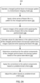
- FIG. 1 illustrates a system 100, according to one implementation, that can measure and correct optical aberrations in a charged particle beam microscope system while the charged particle beam microscope system is operating in a transmission imaging mode.
- the system 100 is illustrated in the context of an exemplary charged particle beam microscope system 104.
- the system 100 is not limited to the particular configuration of the charged particle beam microscope system 104 shown in FIG. 1 and could be used with any charged particle beam microscope system operating in a transmission imaging mode.
- the charged particle beam microscope system 104 includes a charged particle beam microscope column 120 (hereafter, microscope column 120) enclosed in a vacuum chamber 106.
- the microscope column 120 defines an optical axis 116 of the charged particle beam microscope system 104.
- a sample 124 to be investigated can be disposed along the optical axis 116.
- the sample 124 can be supported by a sample holder 140, which in some examples can have capabilities to translate, rotate, and/or tilt the sample 124 relative to the optical axis 116.
- the sample holder 140 can allow different areas of the sample 124 to be positioned relative to the optical axis 116 for investigation.
- a charged particle source 108 e.g., a thermal electron source, Schottky-emission source, field emission source, etc.
- a charged particle beam 112 e.g., an electron beam.
- the charged particle beam 112 is directed along the optical axis 116 such that it can impinge on the sample 124 and interact with the sample 124.
- the charged particle beam 112 passes through the sample 124 to produce an image.
- a camera 136 at the bottom of the microscope column 120 can be operated to capture an image of the sample 124.
- the camera 136 can include, for example, a CCD (charged-coupled device) imaging sensor, a CMOS (complementary metal-oxide-semiconductor) imaging sensor, or, more generally, an array of photodetectors.
- the camera 136 can be operable in a "movie" mode to capture a sequence of images of the sample.
- the microscope column 120 can include various charged particle beam lens systems (hereafter, lens systems) that direct the charged particle beam 112 along the optical axis 116 and configure the charged particle beam 112 to provide a constant illumination covering a desired field of view on the sample 124.
- lens systems can also project the image produced by interaction of the charged particle beam 112 with the sample 124 into a field of view of the camera 136.
- the various lens systems can include a condenser lens system 122, an objective lens system 126, and a projector lens system 130, which can have any suitable configuration to modify the charged particle beam 112 to provide a desired field of view.
- the condenser lens system 122 can be configured to condense the charged particle beam 112 into a nearly parallel beam.
- the objective lens system 126 can be configured to focus the image formed by transmitting the charged particle beam 112 through the sample 124.
- the projector lens system 130 can be configured to project the image coming from the objective lens system 126 to the field of view of the camera 136.
- the condenser lens system 122 can include condenser lenses 122a, 122b and other components, such as a condenser stigmator 122c (i.e., a device to correct axial astigmatism), and a condenser aperture 122d.
- a condenser stigmator 122c i.e., a device to correct axial astigmatism
- condenser aperture 122d i.e., a device to correct axial astigmatism
- the objective lens system 126 can include an objective lens 126a and other components, such as beam deflectors 126b (which can be used to center the beam), an objective stigmator 126c (i.e., a device to correct axial astigmatism), and objective aperture 126d.
- the sample 124 is positioned above the objective lens 126a (in other examples, the sample 124 can be inserted into the objective lens 126a).
- the projector lens system 130 can include, for example, an intermediate lens 130a (e.g., to magnify the image) and projector lenses 130b, 130c.
- the projector lens system 130 can include other components, such as a stigmator, image deflector, and aperture.
- the components of the lens systems can be electro-optical components that are tunable by varying the electrical current applied to the components.
- the various lenses of the lens systems 122, 126, 130 can be electromagnetic lenses.
- An electromagnetic lens modifies charged particle beams by a magnetic field generated by a solenoid. By changing the electric current to the solenoid, the magnetic field can be changed, which would correspondingly change the focal length and magnification of the lens.
- the other components of the lens systems 122, 126, 130 such as the stigmators and beam deflectors, can be electromagnetic devices, which can be tuned in the same manner as described for the electromagnetic lenses.
- the ability to tune the components of the lens systems 122, 126, 130 by varying electrical current supplied to the components can allow aberration corrections to be applied to the microscope column 120 on the fly (e.g., while the charged particle beam microscope system 104 is operating in a transmission imaging mode).
- the lens systems 122, 126, 130 can include other optical components not shown in FIG. 1 or a different configuration of optical components.
- the microscope column 120 can include other optical components near the output of the charged particle source 108.
- the microscope column 120 can include an accelerator stack that can be used to increase the acceleration of the charged particle beam 112 (e.g., prior to condensing the charged particle beam 112).
- the system 100 includes a pattern generator 144 that can generate various patterns.
- the pattern generator 144 can be, for example, a programmable function generator.
- the pattern generator 144 can be configured to generate periodic patterns.
- the system 100 includes beam deflectors 134 inserted in the microscope column 120.
- the beam deflectors 134 can be controlled according to the pattern to tilt the charged particle beam 112 in the X and Y directions over time.
- the beam deflectors 134 can apply tilt motion to the charged particle beam 112 prior to the charged particle beam 112 reaching the sample 124 (e.g., prior to condensing the charged particle beam 112).
- the beam deflectors 134 can be electro-optic deflectors (e.g., electrostatic or magnetic beam deflectors), which would allow the tilt angles applied to the charged particle beam 112 to be changed by varying the electrical current to the beam deflectors.
- the beam deflectors 134 operated according to a pattern, apply a time series of beam tilts to the charged particle beam 112. Each beam tilt produces an image.
- the time series of beam tilts results in a sequence of images. Image shifts between successive (or adjacent) images in the sequence of images can indicate optical aberrations in the microscope system.
- the system 100 can include a frame grabber 148 in communication with the camera 136.
- the frame grabber 148 can, for example, form an interface between the camera 136 and a computing system 154 (e.g., a server).
- the frame grabber 148 is an electronic device that can capture individual image frames from a stream of image data produced by the camera 136.
- the system 100 can include an image shift tracker 152 in communication with the frame grabber 148.
- the image shift tracker 152 can receive image frames from the frame grabber 148 and measure (or compute) the image shift between successive image frames over time.
- the image shift tracker 152 can use any suitable imaging processing technique to measure images shift.
- One example technique is cross-correlation.
- the image shift tracker 152 can be executed by a processor (e.g., GPU, CPU, or FPGA) of the computing device 154.
- the system 100 can include an aberration calculator 156 that determines values for the optical aberrations in a charged particle beam microscope system based on the image shifts measured by the image shift tracker 152.
- optical aberrations that can be found in charged particle beam microscopes and measured are defocus, two-fold astigmatism, three-fold astigmatism, four-fold astigmatism, five-fold astigmatism, sixfold astigmatism, axial coma, fifth order axial coma, spherical aberration, sixth order spherical aberration, star aberration, sixth order star aberration, three-lobe aberration, and rosette aberration.
- the aberration calculator 156 can be configured to determine values for any combination of these optical aberrations as well as other optical aberrations not specifically mentioned.
- the aberration calculator 156 can receive a stream of image shifts from the image shift tracker 152 and compute the optical aberrations in the microscope column 120 based on the image shifts. In one example, the aberration calculator 156 can estimate the optical aberrations by fitting the image shifts to an optical aberration model that provides a relationship between image shifts, beam tilts, and optical aberrations in the microscope column 120. In some examples, the optical aberration model can be extended with one or more auxiliary parameters that are also fitted. The auxiliary parameters can capture variances in the measurements. For example, the time duration between generating a tilt position and actually tilting the beam with the tilt position can vary such that there is an unknown time delay between the beam tilt applied and the sequence of images captured from applying the beam tilt.
- beam tilting control timing can be uncoupled or not synchronized with imaging sensors.
- one such auxiliary parameter can be an unknown time delay or time synchronization between the pattern that controls the beam tilt and the images captured by the camera 136.
- Another example of auxiliary parameters can include sample drift.
- a phase of the periodic tilt pattern can be related to a phase of the detected pattern to provide timing information.
- a portion of a tilt pattern period, between one and two periods, or more than two periods may be sufficient to provide time used to synchronize clock timing between beam controls and image detection.
- Various tilt patterns can be used, including non-periodic movements.
- the aberration calculator 156 can determine values for the optical aberrations based on optimization of a model that provides a relationship between a sequence of images and optical aberrations in the microscope column 120. For example, an image acquired at one tilt angle can be transformed to an image acquired at another tilt angle. The transformation could be parameterized by variables related to optical aberrations. These parameters would then correspond to the model. In an optimization routine, the optical parameters that can maximize the similarity of the transformed images can be found and used to determine values for the optical aberrations. This procedure can be extended to multiple images.
- the aberration calculator 156 can determine values for the optical aberrations from an inference of a neural network that has been trained to predict optical aberrations from image information obtained by applying a series of beam tilts to a charged particle beam in a pattern.
- the trained neural network can receive the sequence of images as input and/or can receive information derived from the sequence of images (e.g., power spectra of the images, image shifts, etc.) as input and generate an inference, which can include a prediction and other information such as confidence of the prediction.
- the aberration calculator 156 can receive the image data directly from the camera 136 or receive image frames from the frame grabber 148, preprocess the image data, and provide the preprocessed image data to the neural network.
- the inference can be a service that is provided via a cloud.
- the system 100 can include an aberration corrector 168 that is communicatively coupled to the aberration calculator 156.
- the aberration corrector 168 can determine corrections to apply to the components of the microscope column 120 (e.g., the components of the lens systems) based on the optical aberrations determined by the aberration calculator 156. For example, where the components are electro-optical components, the aberration corrector 168 can change the electrical current applied to the components in order to change how the components modify the charged particle beam 112.
- the aberration corrector 168 can apply the corrections to the components of the microscope column 120 based on predetermined criteria (e.g., if the optical aberrations exceed predetermined thresholds or if the confidence of an estimated aberration value exceeds a predetermined threshold (e.g., if the absolute value of an estimated aberration value is less than a confidence interval for that optical aberration)).
- predetermined criteria e.g., if the optical aberrations exceed predetermined thresholds or if the confidence of an estimated aberration value exceeds a predetermined threshold (e.g., if the absolute value of an estimated aberration value is less than a confidence interval for that optical aberration)).
- the aberration corrector 168 can determine adjustments to make to the pattern generated by the pattern generator 144 for beam tilting.
- the aberration calculator 156 can provide the optical aberrations with a level of confidence. If the level of confidence is low, the aberration corrector 168 can determine an optimal pattern to use in subsequent beam tilting in order to improve the confidence of the measurements.
- the aberration corrector 168 can further determine the parameters of the optimal pattern (such as base frequency and amplitude) and provide this information to the pattern generator 144.
- the aberration calculator 156 and aberration corrector 168 can be programs or scripts running on a computing system 160 that is communicatively coupled to the charged particle beam microscope system 104.
- the aberration corrector 168 can be in communication with the aberration calculator 156 and the pattern generator 144.
- the computing system 160 can be coupled to a display 164 (e.g., a console of the charged particle beam microscope system 104).
- the computing system 160 can present current aberration values and trends in the aberrations on the display 164.
- the image shift tracker 152, aberration calculator 156, and aberration corrector 168 can be implemented in software and/or hardware.
- Software components of the image shift tracker 152, aberration calculator 156, and aberration corrector 168 can be stored in one or more computer-readable storage media or computer-readable storage devices and executed by one or more processors (e.g., processors in the computing system 160 or 154).
- processors e.g., processors in the computing system 160 or 154.
- Any of the computer-readable media herein can be non-transitory (e.g., volatile memory such as DRAM or SRAM, nonvolatile memory such as magnetic storage, optical storage or the like) and/or tangible.
- FIG. 2A is a flow diagram illustrating a method 200 of measuring and correcting optical aberrations in a charged particle beam microscope system (e.g., the charged particle beam microscope system 104 illustrated in FIG. 1 ) operating in a transmission imaging mode. Operations are illustrated once each and in a particular order in FIG. 2A (and in the others of the flow diagrams discussed therein), but the operations may be reordered and/or repeated as desired and appropriate (e.g., different operations performed may be performed in parallel, as suitable).
- a charged particle beam microscope system e.g., the charged particle beam microscope system 104 illustrated in FIG. 1
- Operations are illustrated once each and in a particular order in FIG. 2A (and in the others of the flow diagrams discussed therein), but the operations may be reordered and/or repeated as desired and appropriate (e.g., different operations performed may be performed in parallel, as suitable).
- the method includes operating a charged particle beam microscope system in a transmission imaging mode.
- the operation 210 can include generating a charged particle beam (e.g., an electron beam) using a charged particle source at the top of the microscope column and directing the charged particle beam to a sample using optical components in the microscope column.
- the charged particle beam interacts with the sample to produce an image.
- the operation 210 can include projecting the image into a field of view of a camera at the bottom of the microscope column.
- the method can include applying a time series of beam tilts in a pattern to the charged particle beam coming out of the charged particle source.
- the operation 220 can include generating the pattern.
- the operation 220 can include applying the time series of beam tilts by traversing the pattern. At each point on the traversal path, the x, y coordinates of the point determine the amount of tilt to apply to the charged particle beam in the X and Y directions.
- the tilt amounts can be used to control the beam deflectors inserted in microscope column to tilt the beam.
- the pattern can be a periodic pattern.
- the periodic pattern can be a Lissajous figure (or Lissajous curve).
- the method can include operating a camera in a movie mode to capture images of the sample. For every beam tilt, the camera can obtain a full image of the sample. Thus, the camera can capture a sequence of images corresponding to applying the time series of beam tilts to the charged particle beam.
- the time between applying the beam tilt and the actual tilting of the beam can vary such that there is an unknown time delay between the beam tilting pattern and the sequence of images captured.
- the optical aberration model can incorporate the unknown time delay as an auxiliary variable to be fitted. Other auxiliary variables can be incorporated in the optical aberration model as well, e.g., beam tilt pattern or sample drift.
- the method can include estimating values for the optical aberrations in the microscope column from the images captured in operation 225.
- the optical aberrations can be estimated from an optical aberration model that relates image shifts to beam tilts and optical aberrations of the microscope column.
- the optical aberrations can be obtained by optimizing a model that provides a relationship between the sequence of images and optical aberrations in the microscope column.
- the optical aberrations can be obtained as an inference of a trained neural network. The inference can include the prediction of the neural network as well as other information such as confidence of the prediction.
- FIG. 2B illustrates one example of operation 230 of FIG. 2A .
- the method includes determining image shifts from a sequence of images captured in operation 225.
- the operation 240 can include receiving image data from the camera and extracting a sequence of images (or image frames) from the image data. Each image will correspond to an image of the sample at a given beam tilt. Any shift between successive (or adjacent) images will depend on the optical aberration of the charged particle beam microscope.
- the operation 240 includes determining these image shifts using any suitable image processing technique, such as cross-correlation.
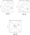
- FIG. 3A shows a beam tilt pattern 300 that can be applied to a charged particle beam
- FIGS. 3B-3E show expected image shift patterns 302, 304, 306, 308 produced from applying the beam tilt pattern 300 due to various types of microscope aberrations (e.g., defocus, astigmatism, coma, and spherical aberration).
- FIGS. 3B-3E show the movement of the image of the sample over time as the beam tilt pattern is applied.
- the beam tilt pattern will not induce a shift in the images of the sample collected over time. However, if there are aberrations in the microscope, the pattern formed by the movement of the sample will be different from the applied beam tilt pattern (e.g., scaled and/or distorted).
- the image shift pattern 302 shown in FIG. 3B corresponds to an example where the optical aberration in the microscope is defocus.
- the image shift pattern 302 and the applied beam tilt pattern 300 are linearly dependent (i.e., the image shift pattern 302 is scaled relative to the applied beam tilt pattern 300 - the amount of defocus is the scaling factor between the figures shown in FIGS. 3A and 3B ).
- the image shift pattern 304 shown in FIG. 3C corresponds to an example where the optical aberrations in the microscope are defocus and astigmatism.
- the image shift pattern 304 compared to the applied beam tilt pattern 300 is deformed in one direction (by astigmatism) and scaled (by defocus).
- the image shift pattern 306 in FIG. 3D corresponds to an example where the optical aberrations in the microscope are defocus, astigmatism, and coma.
- the image shift pattern 306 compared to the applied beam tilt pattern 300 is distorted asymmetrically (by coma), deformed in one direction (by astigmatism), and scaled (by defocus).
- the image shift pattern 308 shown in FIG. 3E corresponds to an example where the optical aberrations in the microscope are defocus, astigmatism, coma, and spherical aberration.
- the image shift pattern 308 compared to the applied beam tilt pattern 300 is distorted radially (by spherical aberration), distorted asymmetrically (by coma), deformed in one direction (by astigmatism), and scaled (by defocus).
- FIG. 4A illustrates another example of a beam tilt pattern 400 that can be applied to a charged particle beam
- FIGS. 4B-4D illustrate expected image shift patterns 402, 404, 406 produced from applying the beam tilt pattern 400 due to various types of microscope aberrations (e.g., defocus, astigmatism, and coma).
- the beam tilt pattern 400 is a circular pattern (which is a special case of a Lissajous figure).
- FIGS. 4B-4D show the movement of the image of the sample over time as the beam tilt pattern is applied. If there are no optical aberrations in the microscope, the beam tilt pattern will not induce a shift in the images of the sample collected over time. However, if there are aberrations in the microscope, the pattern formed by the movement of the sample will be different from the applied beam tilt pattern (e.g., scaled and/or distorted).
- the image shift pattern 402 in FIG. 4B corresponds to an example where the optical aberration in the microscope is defocus (the image shift pattern 402 is scaled compared to the applied beam tilt pattern 400 - the amount of defocus is the scaling factor between the figures shown in FIGS. 4A and 4B ).
- the image shift pattern 404 in FIG. 4C corresponds to an example where the optical aberrations in the microscope are defocus and astigmatism (the image shift pattern 404 is scaled and deformed in one direction).
- the image shift pattern 406 in FIG. 4D corresponds to an example where the optical aberrations in the microscope are defocus, astigmatism, and coma (the image shift pattern 406 is scaled, deformed in one direction, and distorted asymmetrically).
- a circular pattern such as the beam tilt pattern 400 shown in FIG. 4A , can capture low order aberrations (e.g., defocus) effectively but may be less sensitive to higher order aberrations.
- a more complex Lissajous figure such as the beam tilt pattern 300 shown in FIG. 3A , may be more suitable.
- the method includes estimating values for selected optical aberrations from the image shifts obtained in operation 240.
- the aberration values can be estimated by fitting the image shifts to an optical aberration model for the charged particle beam microscope system.
- Equation (3) is an example of an optical aberration model.
- the model of Equation (3) can obtain values for defocus, astigmatism (astigX, astigY), coma (comaX, comaY), threefold astigmatism (threefoldX, threefoldY), spherical aberration (spherical), star aberration (starX, starY), and fourfold astigmatism (fourfoldX, fourfoldY).
- shiftX shiftY tx ty
- the vector on the right hand side of the equation contains values for optical aberrations for a given state of the optical system of the microscope system at a certain moment in time.
- the induced image shift will be given by (shiftX, shifty), which can be measured from images captured while applying the beam tilts (e.g., in operation 240).
- the measured shiftX, shiftY and known tx, ty can be fitted into the model of Equation (3) to obtain the estimated values for the optical aberrations.
- the parameters tx, ty are time-dependent, which allows unknown time delay between the applied beam tilt pattern and the induced image shift pattern to be factored into the model for fitting. Variations of the optical aberration model can incorporate other auxiliary parameters, such as beam tilt pattern and/or sample drift.
- the method includes determining corrections to apply to the optical components in the microscope column based on the aberration values estimated in operation 230 (or in operation 245 in FIG. 2B ).
- the method can include applying the corrections determined in operation 250 to one or more of the optical components in the microscope column based on predetermined criteria. For example, if the estimated values for one or more of the selected aberrations are above predetermined thresholds, the corrections could be applied. Alternatively, if the estimated values for the selected aberrations are below predetermined thresholds, the corrections may not be applied. However, the corrections can be stored and used during post processing of the captured images of the sample.
- the method can include adjusting the pattern used in beam tilting in operation 220 based on predetermined factors.
- the pattern can be adjusted, for example, if an accuracy of the estimated values for one or more selected optical aberrations is below a predetermined threshold, a quality of the images in the sequence of images is below a predetermined threshold, and/or there are external disturbances (e.g., mechanical vibrations) while capturing the sequence of images.
- the pattern can be adjusted by changing the parameters of the pattern (e.g., the base frequency and/or amplitude of the pattern can be changed) or by selecting a new pattern that is optimal for the configuration of the microscope and sample.
- the operations 220-270 can be repeated until the end of a planned acquisition or until the aberrations are measured with a desired accuracy or until aberrations are tuned to the desired values with desired accuracy.
- the aberration measurements over time can be displayed on a screen and monitored.
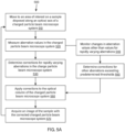
- FIG. 5A illustrates an example method 500 of operating a charged particle beam microscope system with monitoring and correction of aberrations (e.g., the system 100 illustrated in FIG. 1 ).
- the method 500 is optimized to accurately and precisely measure rapidly varying aberrations.
- operations are illustrated once each and in a particular order in FIG. 5A , but the operations may be reordered and/or repeated as desired and appropriate (e.g., different operations performed may be performed in parallel, as suitable).
- the method 500 may include performing any suitable combinations of the operations presented therein in parallel.
- the method 500 includes moving to an area of interest on the sample.
- the method 500 includes measuring values of aberrations in the charged particle beam microscope system.
- the measurements can be made according to operations 210-230 in FIG. 2A .
- the method 500 includes determining corrections for rapidly varying aberrations (e.g., defocus) in the charged particle beam microscope system.
- the method 500 includes monitoring changes in values for other optical aberrations (e.g., optical aberrations that are not rapidly varying, such as two-fold astigmatism, three-fold astigmatism, four-fold astigmatism, five-fold astigmatism, sixfold astigmatism, axial coma, fifth order axial coma, spherical aberration, sixth order spherical aberration, star aberration, sixth order star aberration, three-lobe aberration, or rosette aberration).
- optical aberrations e.g., optical aberrations that are not rapidly varying, such as two-fold astigmatism, three-fold astigmatism, four-fold astigmatism, five-fold astigmatism, sixfold astigmatism, axial coma, fifth order axial coma, spherical aberration, sixth order spherical aberration, star aberration, sixth order star aberration, three-lobe aberration, or rosette aberration.
- the method 500 can include determining corrections for other aberrations having values exceeding predetermined thresholds.
- the method 500 includes applying any corrections determined in operations 530 and 540 to the optical column of the charged particle beam microscope system (or microscope column).
- the method 500 includes acquiring an image of the sample with the corrected charged particle beam microscope system. After acquiring the image, the method 500 can return to operation 510 to process another area of the sample.
- optical aberrations e.g., defocus
- other optical aberrations e.g., coma and astigmatism
- the optical corrections can be determined and applied more quickly for the optical aberrations that can be identified using a relatively small amount of data.
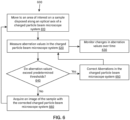
- FIG. 5B illustrates an example method 580 of operating a charged particle beam microscope system with monitoring and correction of aberrations (e.g., the system 100 illustrated in FIG. 1 ) based on the principle of applying optical corrections at different frequencies.
- FIG. 2A and the others of the accompanying flow diagrams operations are illustrated once each and in a particular order in FIG. 5B , but the operations may be reordered and/or repeated as desired and appropriate (e.g., different operations performed may be performed in parallel, as suitable).
- the method 580 may include performing any suitable combinations of the operations presented therein in parallel.
- a first set of one or more optical aberrations and a second set of one or more optical aberrations are determined.
- the first set of one or more optical aberrations is different from the second set of one or more optical aberrations (e.g., the one or more optical aberrations in the first set are different than the one or more optical aberrations in the second set).
- the differences between the first and second sets can be based on the amount of data required to appropriately identify the optical aberrations and/or on the drift rate (i.e., the speed at which the optical aberration significantly changes its value) in the microscope system.
- the first set can include one or more optical aberrations that can be identified using a relatively small amount of data (e.g., defocus).
- the second set can include one or more optical aberrations that require a relatively large amount of data to be appropriately identified (e.g., coma and astigmatism).
- the method 580 includes moving to an area of interest on a sample disposed along an optical axis of the charged particle beam microscope system.
- the method 580 includes acquiring images of the sample while operating the charged particle beam microscope system.
- the images can be acquired, for example, as described in operations 210-225 in FIG. 2A .
- the method 580 includes determining a first optical aberration output set for the charged particle beam microscope system.
- the first optical aberration output set includes values for the first set of one or more optical aberrations in the charged particle beam microscope system.
- a first input set for determining the first optical aberration output set includes one or more of the images acquired in operation 583.
- the values for the first set of one or more optical aberrations can be determined, for example, using the aberration calculator (156 in FIG. 1 ) and the first input set.
- the first optical aberration output set can further include values for one or more of the second set of one or more optical aberrations in the charged particle beam microscope system.
- the values for the second set can be determined, for example, using the aberration calculator and the first input set.
- the values for the first set and second set can be determined within the same aberration calculation (e.g., using the same optical aberration model, optimization of a model, or trained neural network).
- the values in the first optical aberration output set can include estimated values of the optical aberrations and confidence of the estimation.
- the method 580 includes applying corrections (or adjustments) to the charged particle beam microscope system at a first frequency to mitigate the first set of one or more optical aberrations.
- the corrections to apply to the first set of one or more optical aberrations are determined based on the values corresponding to the first set of one or more optical aberrations in the first optical aberration output set determined in operation 584.
- the corrections can be applied by varying electrical currents supplied to one or more electro-optical components of the charged particle beam microscope system.
- the method 580 includes determining a second optical aberration output set for the charged particle beam microscope system.
- the second optical aberration output set includes values for the second set of one or more optical aberrations in the charged particle microscope system.
- a second input set for determining the second optical aberration output set can include one or more of the images acquired in operation 583 or can include some values from the first optical aberration output set (e.g., the values determined for one or more of the second set of one or more optical aberrations in operation 584).
- the values for the second set of one or more optical aberrations can be determined using the aberration calculator (156 in FIG. 1 ) and the second input set.
- the values determined for one or more of the second set of one or more optical aberrations in operation 584 can be accumulated over time and used to determine the values for the second optical aberration output set (e.g., the values determined for an optical aberration in the second set in operation 584 over time can be averaged to determine the corresponding value for the optical aberration in the second optical aberration output set).
- the operation 588 may run at a slower rate compared to the operation 584.
- one or more executions of determining the first optical aberration output set can be completed before a single execution of determining the second optical aberration output set is completed (allowing for the aforementioned accumulation of data from operation 584 to determine values for the second optical aberration output set).
- the method 580 includes applying corrections (or adjustments) to the charged particle beam microscope system at a second frequency to mitigate the second set of one or more optical aberrations whose values were determined in operation 588.
- the second frequency in operation 590 is different from the first frequency in operation 586.
- the second frequency is less than the first frequency so that the corrections in operation 586 are applied more frequently than the corrections in operation 590.
- the second frequency can be selected based on the time required for each iteration of operation 588 to determine the second optical aberration set sufficiently accurately.
- the corrections can be applied by varying electrical currents supplied to one or more electro-optical components of the charged particle beam microscope system.
- the method 580 can include determining if the values determined in any of operations 584 and 588 exceed predetermined thresholds. If the values exceed predetermined thresholds, the method can return to operation 583 to acquire more images of the sample with the corrections applied to the charged particle beam microscope system.
- the method 580 can include acquiring an image of the sample with the corrected charged particle beam microscope system.
- the image can be acquired when it is determined that the aberration values determined in operations 584 and 588 do not exceed predetermined thresholds.
- the method 580 can return to operation 582 to process another area of the sample or the same area of the sample.
- operation 582 can be performed in parallel to other operations in the method 580 (i.e., determining aberration values and making corrections to the microscope system can be performed while moving the sample relative to the microscope system).
- FIG. 6 illustrates an example method 600 for acquiring an image of a sample with a charged particle beam microscope system with monitoring and correction of aberrations.
- operations are illustrated once each and in a particular order in FIG. 6 , but the operations may be reordered and/or repeated as desired and appropriate (e.g., different operations performed may be performed in parallel, as suitable).
- the method 600 may include performing any suitable combinations of the operations presented therein in parallel.
- the method 600 includes moving to an area of interest on the sample.
- the method 600 includes measuring values of aberrations in the charged particle beam microscope system according to operations 210-230 in FIG. 2A .
- the method 600 includes monitoring changes in the optical aberrations over time.
- the changes in the optical aberrations can be presented in a display, for example, in the form of trend graphs.
- monitoring of the changes in the optical aberrations could be omitted.
- the method 600 includes determining if any of the aberration values exceed a predetermined threshold. If any of the aberration values exceed a predetermined threshold, the method 600 continues at operation 650. Otherwise, the method 600 continues at operation 660.
- the method 600 includes determining corrections for the aberrations exceeding predetermined thresholds and applying the corrections to the optical column of the charged particle beam microscope system. After applying the corrections, the method 600 returns to operation 620 to repeat measurement of the aberration values. This can continue until there are no aberration values that exceed predetermined thresholds.
- the method 600 includes acquiring an image of the sample with the corrected charged particle beam microscope system. After acquiring the image, the method 600 can return to operation 610 to process another area of the sample.
- the operations in example methods 500, 580, 600 can be controlled by a computer program, which can be stored on one or more computer-readable storage media and executed by one or more processors of a computing system.
- the computer-readable storage media can be non-transitory (e.g., volatile memory such as DRAM or SRAM, nonvolatile memory such as magnetic storage, optical storage, or the like) and/or tangible.
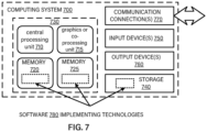
- FIG. 7 is a block diagram of a generalized example computing system (or computing environment) that may be used in the methods described herein.
- the methods can use a single computing system.
- the methods can use multiple computing systems, which may communicate over a network.
- the computing system 700 includes one or more processing units 710, 715 and memory 720, 725.
- the processing units 710, 715 execute computer-executable instructions.
- a processing unit can be a general-purpose central processing unit (CPU), processor in an application-specific integrated circuit (ASIC) or any other type of processor.
- ASIC application-specific integrated circuit
- FIG. 7 shows a central processing unit 710 as well as a graphics processing unit or co-processing unit 715.
- the tangible memory 720, 725 may be volatile memory (e.g., registers, cache, RAM), non-volatile memory (e.g., ROM, EEPROM, flash memory, etc.), or some combination of the two, accessible by the processing unit(s).
- the memory 720, 725 stores software 780 implementing one or more innovations described herein, in the form of computer-executable instructions suitable for execution by the processing unit(s).
- Software 780 can include, for example, one or more of the image shift tracker 152, the aberration calculator 156, the aberration corrector 168, or the logic of the methods 500, 580, 600.
- a computing system may have additional features.
- the computing system 700 can include storage 740, one or more input devices 750, one or more output devices 760, and one or more communication connections 770.
- An interconnection mechanism such as a bus, controller, or network interconnects the components of the computing system 700.
- operating system software provides an operating environment for other software executing in the computing system 700, and coordinates activities of the components of the computing system 700.
- the tangible storage 740 may be removable or non-removable, and includes magnetic disks, magnetic tapes or cassettes, CD-ROMs, DVDs, or any other medium which can be used to store information in a non-transitory way and which can be accessed within the computing system 700.
- the storage 740 stores instructions for the software 780 implementing one or more innovations described herein.
- the input device(s) 750 may be a touch input device such as a keyboard, mouse, pen, or trackball, a voice input device, a scanning device, or another device that provides input to the computing system 700.
- the output device(s) 760 may be a display, printer, speaker, CD-writer, or another device that provides output from the computing system 700.
- the communication connection(s) 770 enable communication over a communication medium to another computing entity.
- the communication medium conveys information such as computer-executable instructions, audio or video input or output, or other data in a modulated data signal.
- a modulated data signal is a signal that has one or more of its characteristics set or changed in such a manner as to encode information in the signal.
- communication media can use an electrical, optical, RF, or other carrier.
- this application discloses the additional examples enumerated below. It should be noted that one feature of an example in isolation or more than one feature of the example taken in combination and, optionally, in combination with one or more features of one or more further examples are further examples also falling within the disclosure of this application.
- Example 1 is a method including, with a charged particle beam microscope system operating in a transmission imaging mode, directing a charged particle beam to a sample including applying a time series of beam tilts in a pattern to the charged particle beam to produce a sequence of images, wherein at least some of the images in the sequence of images are captured while the charged particle beam is transitioning between one beam tilt in the time series of beam tilts and a sequentially adjacent beam tilt in the time series of beam tilts, and wherein the pattern is configured to induce image changes between the images in the sequence of images that are indicative of optical aberrations in the charged particle beam microscope system.
- the method includes capturing the sequence of images.
- Example 2 includes the subject matter of Example 1 and further specifies that the pattern is a periodic pattern.
- Example 3 includes the subject matter of Example 2 and further specifies that the periodic pattern is a Lissajous figure.
- Example 4 includes the subject matter of any of Examples 1-3 and further includes generating a set of one or more optical aberration values for the charged particle beam microscope system from the sequence of images.
- Example 5 includes the subject matter of Example 4, wherein the image changes comprise induced image shifts, and wherein generating the set of one or more optical aberration values for the charged particle beam microscope system from the sequence of images comprises measuring the induced image shifts between successive images in the sequence of images.
- Example 6 includes the subject matter of Example 5, wherein generating the set of one or more optical aberration values for the charged particle beam microscope system from the sequence of the images further includes obtaining an inference from a neural network model trained to identify a set of optical aberrations from input data derived from the sequence of images.
- Example 7 includes the subject matter of Example 5, wherein generating the set of one or more optical aberration values for the charged particle beam microscope system from the sequence of the images further includes fitting the induced image shifts to an optical aberration model describing a relationship between the induced image shifts, the beam tilts, and the set of optical aberrations.
- Example 8 includes the subject matter of Example 7 and further specifies that the optical aberration model incorporates an unknown time delay between the pattern and the sequence of images.
- Example 9 includes the subject matter of any of Examples 4-8, wherein generating the set of one or more optical aberration values for the charged particle beam microscope system from the sequence of images comprises estimating a value for one or more of defocus, two-fold astigmatism, three-fold astigmatism, four-fold astigmatism, five-fold astigmatism, sixfold astigmatism, axial coma, fifth order axial coma, spherical aberration, sixth order spherical aberration, star aberration, sixth order star aberration, three-lobe aberration, and rosette aberration.
- Example 10 includes the subject matter of any one of Examples 4-9 and further includes determining optical corrections for the charged particle beam microscope system based on the set of one or more optical aberration values.
- Example 11 includes the subject matter of Example 10 and further includes applying the optical corrections for the charged particle beam microscope system to one or more optical components of the charged particle beam microscope system.
- Example 12 includes the subject matter of Example 10 and further includes adjusting the pattern based on one or more of accuracy of the set of one or more optical aberration values, quality of the images in the sequence of images, and external disturbances while capturing the sequence of images.
- Example 13 includes the subject matter of any one of Examples 4-12 and further includes monitoring changes in the set of one or more optical aberrations over time.
- Example 14 is a method including receiving, by one or more processors, a sequence of images captured while applying a time series of beam tilts in a periodic pattern to a charged particle beam transmitted along an optical axis of an optical column of a charged particle beam microscope system and through a sample disposed along the optical axis.
- the method includes estimating, by the one or more processors, values for one or more optical aberrations produced by the optical column from the sequence of images.
- Example 15 includes the subject matter of Example 14 and further includes determining one or more optical corrections for one or more optical components in the optical column; and selectively applying the one or more optical corrections to the one or more optical components.
- Example 16 includes the subject matter of any one of Examples 14-15 and further specifies that the periodic pattern is a Lissajous pattern.
- Example 17 is a system including a charged particle source that emits a charged particle beam; an optical column defining an optical axis and comprising one or more optical components configured to form the charged particle beam into a field of view of a sample disposed along the optical axis; a pattern generator configured to generate a pattern; one or more beam deflectors disposed along the optical axis and controllable by the pattern to apply a time series of beam tilts to the charged particle beam; an imaging sensor positioned along the optical axis to capture images of the sample; one or more processors; and one or more computer-readable storage media storing instructions that when executed by the one or more processors cause the one or more processors to receive a sequence of images captured by the imaging sensor during application of the time series of beam tilts and cause the one or more processors to generate a set of one or more optical aberration values for the optical system from the sequence of images, wherein at least some of the images in the sequence of images are captured during movement of the charged particle beam between consecutive tilts in the time series of beam tilt
- Example 18 includes the subject matter of Example 17 and further specifies that the one or more computer-readable storage media further store instructions that when executed by the one or more computing devices cause the one or more computing devices to determine induced image shifts in the sequence of images and determine the values for the one or more optical aberrations from the induced image shifts and an applied time series of beam tilts corresponding to the induced image shifts.
- Example 19 includes the subject matter of Example 17 and further specifies that the one or more computer-readable storage media further store instructions that when executed by the one or more computing devices cause the one or more computing devices to determine one or more optical corrections for the one or more optical components based on the set of one or more optical aberration values.
- Example 20 includes the subject matter of any one of Examples 17-19, and further specifies that the one or more computer-readable storage media further store instructions that when executed by the one or more computing devices cause the one or more computing devices to determine adjustments to the pattern generated by the pattern generator based on a confidence level of the values determined for the one or more optical aberrations.
- Example 21 includes the subject matter of any one of Examples 17-20, and further specifies that the pattern generator is configured to generate a periodic pattern.
- Example 22 is a method of operating a charged particle beam microscope system including determining a first optical aberration output set, wherein the first aberration output set includes values for a first set of one or more optical aberrations in the charged particle beam microscope system, based on a first input set that includes one or more acquired images; applying adjustments, based on the first optical aberration output set, to the charged particle beam microscope system at a first frequency to mitigate optical aberrations in the first set; determining values for a second optical aberration output set that includes values for a second set of one or more optical aberrations in the charged particle beam system, wherein the one or more optical aberrations of the second set are different than the one or more optical aberrations in the first set, based on a second input set that includes at least some of the first input set or the first optical aberration output; and applying adjustments, based on the second optical aberration output set, to the charged particle beam microscope system at a second frequency to mitigate aberrations in the second set, wherein the second frequency is less than the first frequency.
- Example 23 includes the subject matter of Example 22 and further specifies that the first set of one or more optical aberrations includes defocus.
- Example 24 includes the subject matter of any one of Examples 22-23 and further specifies that the second set of one or more optical aberrations includes coma or astigmatism.
- Example 25 includes the subject matter of any one of Examples 22-24, wherein determining the first optical aberration output set based on the first input set includes determining at least some values for one or more optical aberrations in the second set, and wherein the at least some of the first optical aberration output set included in the second input set includes the at least some values.
Landscapes
- Chemical & Material Sciences (AREA)
- Analytical Chemistry (AREA)
- Analysing Materials By The Use Of Radiation (AREA)
Abstract
Description
- The field relates to charged particle beam microcopy.
- Transmission electron microscopy (TEM) is a technique in which a beam of electrons is transmitted through a thin sample to form an image. The image is formed by the interaction of the electrons with atoms of the sample as the electrons are transmitted through the sample. The image can be captured by a camera. TEM is capable of producing high resolution images due to the small wavelength of the transmitted electrons. Sufficiently high resolution images can be used to investigate and analyze the structural details of the sample on an atomic scale. However, optical aberrations in the microscope can limit the resolution of the images.
-
-
FIG. 1 is a block diagram of a system for measuring and correcting optical aberrations in a charged particle beam microscope system operating in a transmission imaging mode, in accordance with various implementations. -
FIGS. 2A and2B are flow diagrams of a method for measuring and correcting optical aberrations in a charged particle beam microscope system operating in a transmission imaging mode, in accordance with various implementations. -
FIG. 3A is a graph of a Lissajous figure beam tilt pattern. -
FIG. 3B is a graph of an expected induced image shift pattern produced by the Lissajous figure beam tilt pattern depicted inFIG. 3A when there is defocus in the charged particle beam microscope system. -
FIG. 3C is a graph of an expected induced image shift pattern produced by the Lissajous figure beam tilt pattern depicted inFIG. 3A when there is defocus and astigmatism in the charged particle beam microscope system. -
FIG. 3D is a graph of an expected induced image shift pattern produced by the Lissajous figure beam tilt pattern depicted inFIG. 3A when there is defocus, coma, and astigmatism in the charged particle beam microscope system. -
FIG. 3E is a graph of an expected induced image shift pattern produced by the Lissajous figure beam tilt pattern depicted inFIG. 3A when there is defocus, coma, astigmatism, and spherical aberration in the charged particle beam microscope system. -
FIG. 4A is a graph of a circular beam tilt pattern. -
FIG. 4B is a graph of expected induced image shift produced by the circular pattern depicted inFIG. 4A when there is defocus in the charged particle beam microscope system. -
FIG. 4C is a graph of expected induced image shift produced by the circular pattern depicted inFIG. 4A when there is defocus and astigmatism in the charged particle beam microscope system. -
FIG. 4D is a graph of expected induced image shift produced by the circular pattern depicted inFIG. 4A when there is defocus, astigmatism, and coma in the charged particle beam microscope system. -
FIG. 5A is a flow diagram of an example method of operating a charged particle beam microscope system with monitoring and correction of aberrations. -
FIG. 5B is a flow diagram of another example method of operating a charged particle beam microscope system with monitoring and correction of aberrations. -
FIG. 6 is a flow diagram of another example method of operating a charged particle beam microscope system with monitoring and correction of aberrations. -
FIG. 7 is a block diagram of a generalized computing system of a suitable computing environment that may be used in methods implementing monitoring and correction of optical aberrations in a charged particle beam microscope system. - The subject matter disclosed herein pertains to methods and systems that measure and correct optical aberrations in charged particle beam microscope systems, e.g., operating in a transmission imaging mode. Examples of optical aberrations that can be measured and corrected include, but are not limited to, defocus, two-fold astigmatism, three-fold astigmatism, four-fold astigmatism, five-fold astigmatism, sixfold astigmatism, axial coma, fifth order axial coma, spherical aberration, sixth order spherical aberration, star aberration, sixth order star aberration, three-lobe aberration, and rosette aberration.
- In one or more implementations, a system includes a charged particle source that emits a charged particle beam, an optical system defining an optical axis and including one or more optical components configured to form the charged particle beam into a field of view of a sample disposed along the optical axis, a pattern generator configured to generate a pattern, one or more beam deflectors disposed along the optical axis and controllable by the pattern to apply a time series of beam tilts to the charged particle beam, and an imaging sensor positioned along the optical axis to capture images of the sample.
- In one or more implementations, while operating the charged particle beam microscope system in a transmission imaging mode and directing a charged particle beam to a sample, a time series of beam tilts is applied in a pattern to the charged particle beam to produce a sequence of images. At least some of the images in the sequence of images are captured while the charged particle beam is transitioning between one beam tilt in the time series of beam tilts and a sequentially adjacent beam tilt in the time series of beam tilts. In one or more examples, the sequence of images can be analyzed to determine optical aberrations in the microscope system.
- In one or more examples, the pattern is configured such that the beam tilts induce image changes (e.g., image shifts) in the sequence of images that can be correlated to optical aberrations in the microscope system. In one or more examples, image changes can be determined from the sequence of images and used to estimate one or more optical aberration values for the microscope system. In other examples, one or more optical aberration values can be determined by a trained neural network that receives the sequence of images or information derived from the sequence of images (e.g., power spectra of the images) as input data.
- In one or more examples, the beam tilt pattern can be a periodic pattern, such as a Lissajous figure. The use of periodic patterns can make it possible to determine an unknown time delay and unknown deviation in frequency of the applied beam tilt pattern in relation to the measured image changes over time. The periodic patterns can also enable a system that is robust against other effects that can induce image changes (e.g., specimen drift and mechanical vibrations), allowing signal processing to be used to separate the different signal sources.
- The subject matter is described with implementations and examples. In some cases, as will be recognized by one skilled in the art, the disclosed implementations and examples may be practiced without one or more of the disclosed specific details, or may be practiced with other methods, structures, and materials not specifically disclosed herein. All the implementations and examples described herein and shown in the drawings may be combined without any restrictions to form any number of combinations, unless the context clearly dictates otherwise, such as if the proposed combination involves elements that are incompatible or mutually exclusive. The sequential order of the acts in any process described herein may be rearranged, unless the context clearly dictates otherwise, such as if one act requires the result of another act as input.
- In the interest of conciseness, and for the sake of continuity in the description, same or similar reference characters may be used for same or similar elements in different figures, and description of an element in one figure will be deemed to carry over when the element appears in other figures with the same or similar reference character. In some cases, the term "corresponding to" may be used to describe correspondence between elements of different figures. In an example usage, when an element in a first figure is described as corresponding to another element in a second figure, the element in the first figure is deemed to have the characteristics of the other element in the second figure, and vice versa, unless stated otherwise.
- The word "comprise" and derivatives thereof, such as "comprises" and "comprising", are to be construed in an open, inclusive sense, that is, as "including, but not limited to". The singular forms "a", "an", "at least one", and "the" include plural referents, unless the context dictates otherwise. The term "and/or", when used between the last two elements of a list of elements, means any one or more of the listed elements. The term "or" is generally employed in its broadest sense, that is, as meaning "and/or", unless the context clearly dictates otherwise. When used to describe a range of dimensions, the phrase "between X and Y" represents a range that includes X and Y. As used herein, an "apparatus" may refer to any individual device, collection of devices, part of a device, or collections of parts of devices.
-
FIG. 1 illustrates asystem 100, according to one implementation, that can measure and correct optical aberrations in a charged particle beam microscope system while the charged particle beam microscope system is operating in a transmission imaging mode. Thesystem 100 is illustrated in the context of an exemplary charged particlebeam microscope system 104. However, thesystem 100 is not limited to the particular configuration of the charged particlebeam microscope system 104 shown inFIG. 1 and could be used with any charged particle beam microscope system operating in a transmission imaging mode. - In the illustrated example, the charged particle
beam microscope system 104 includes a charged particle beam microscope column 120 (hereafter, microscope column 120) enclosed in avacuum chamber 106. Themicroscope column 120 defines anoptical axis 116 of the charged particlebeam microscope system 104. - A
sample 124 to be investigated can be disposed along theoptical axis 116. Thesample 124 can be supported by asample holder 140, which in some examples can have capabilities to translate, rotate, and/or tilt thesample 124 relative to theoptical axis 116. Thesample holder 140 can allow different areas of thesample 124 to be positioned relative to theoptical axis 116 for investigation. - At the top of the
microscope column 120 is a charged particle source 108 (e.g., a thermal electron source, Schottky-emission source, field emission source, etc.) that emits a charged particle beam 112 (e.g., an electron beam). The chargedparticle beam 112 is directed along theoptical axis 116 such that it can impinge on thesample 124 and interact with thesample 124. The chargedparticle beam 112 passes through thesample 124 to produce an image. - A
camera 136 at the bottom of themicroscope column 120 can be operated to capture an image of thesample 124. Thecamera 136 can include, for example, a CCD (charged-coupled device) imaging sensor, a CMOS (complementary metal-oxide-semiconductor) imaging sensor, or, more generally, an array of photodetectors. In one example, thecamera 136 can be operable in a "movie" mode to capture a sequence of images of the sample. - The
microscope column 120 can include various charged particle beam lens systems (hereafter, lens systems) that direct the chargedparticle beam 112 along theoptical axis 116 and configure the chargedparticle beam 112 to provide a constant illumination covering a desired field of view on thesample 124. In some examples, the various lens systems can also project the image produced by interaction of the chargedparticle beam 112 with thesample 124 into a field of view of thecamera 136. - In some examples, the various lens systems can include a
condenser lens system 122, anobjective lens system 126, and aprojector lens system 130, which can have any suitable configuration to modify the chargedparticle beam 112 to provide a desired field of view. Thecondenser lens system 122 can be configured to condense the chargedparticle beam 112 into a nearly parallel beam. Theobjective lens system 126 can be configured to focus the image formed by transmitting the chargedparticle beam 112 through thesample 124. Theprojector lens system 130 can be configured to project the image coming from theobjective lens system 126 to the field of view of thecamera 136. - In some examples, the
condenser lens system 122 can includecondenser lenses condenser stigmator 122c (i.e., a device to correct axial astigmatism), and acondenser aperture 122d. - In some examples, the
objective lens system 126 can include anobjective lens 126a and other components, such asbeam deflectors 126b (which can be used to center the beam), anobjective stigmator 126c (i.e., a device to correct axial astigmatism), andobjective aperture 126d. In the illustrated example, thesample 124 is positioned above theobjective lens 126a (in other examples, thesample 124 can be inserted into theobjective lens 126a). - In some examples, the
projector lens system 130 can include, for example, anintermediate lens 130a (e.g., to magnify the image) andprojector lenses projector lens system 130 can include other components, such as a stigmator, image deflector, and aperture. - The components of the lens systems can be electro-optical components that are tunable by varying the electrical current applied to the components. For example, the various lenses of the
lens systems lens systems lens systems microscope column 120 on the fly (e.g., while the charged particlebeam microscope system 104 is operating in a transmission imaging mode). - The
lens systems FIG. 1 or a different configuration of optical components. Themicroscope column 120 can include other optical components near the output of the chargedparticle source 108. For example, themicroscope column 120 can include an accelerator stack that can be used to increase the acceleration of the charged particle beam 112 (e.g., prior to condensing the charged particle beam 112). - The
system 100 includes apattern generator 144 that can generate various patterns. Thepattern generator 144 can be, for example, a programmable function generator. In some examples, thepattern generator 144 can be configured to generate periodic patterns. In one example, the periodic pattern can be a Lissajous figure. Lissajous figure is given by the following parametric equations:

- The Lissajous figure can be as simple as a circle (e.g., the parametric equations (1) and (2) give a circle when a/b = 1, A = B, and δ = π/2 radians) or can be more complex (e.g., the ratio a/b is not equal to 1).
- The
system 100 includesbeam deflectors 134 inserted in themicroscope column 120. Thebeam deflectors 134 can be controlled according to the pattern to tilt the chargedparticle beam 112 in the X and Y directions over time. Thebeam deflectors 134 can apply tilt motion to the chargedparticle beam 112 prior to the chargedparticle beam 112 reaching the sample 124 (e.g., prior to condensing the charged particle beam 112). Thebeam deflectors 134 can be electro-optic deflectors (e.g., electrostatic or magnetic beam deflectors), which would allow the tilt angles applied to the chargedparticle beam 112 to be changed by varying the electrical current to the beam deflectors. - The beam deflectors 134, operated according to a pattern, apply a time series of beam tilts to the charged
particle beam 112. Each beam tilt produces an image. Thus, the time series of beam tilts results in a sequence of images. Image shifts between successive (or adjacent) images in the sequence of images can indicate optical aberrations in the microscope system. - The
system 100 can include aframe grabber 148 in communication with thecamera 136. Theframe grabber 148 can, for example, form an interface between thecamera 136 and a computing system 154 (e.g., a server). Theframe grabber 148 is an electronic device that can capture individual image frames from a stream of image data produced by thecamera 136. - The
system 100 can include animage shift tracker 152 in communication with theframe grabber 148. Theimage shift tracker 152 can receive image frames from theframe grabber 148 and measure (or compute) the image shift between successive image frames over time. Theimage shift tracker 152 can use any suitable imaging processing technique to measure images shift. One example technique is cross-correlation. In one example, theimage shift tracker 152 can be executed by a processor (e.g., GPU, CPU, or FPGA) of thecomputing device 154. - The
system 100 can include anaberration calculator 156 that determines values for the optical aberrations in a charged particle beam microscope system based on the image shifts measured by theimage shift tracker 152. Examples of optical aberrations that can be found in charged particle beam microscopes and measured are defocus, two-fold astigmatism, three-fold astigmatism, four-fold astigmatism, five-fold astigmatism, sixfold astigmatism, axial coma, fifth order axial coma, spherical aberration, sixth order spherical aberration, star aberration, sixth order star aberration, three-lobe aberration, and rosette aberration. Theaberration calculator 156 can be configured to determine values for any combination of these optical aberrations as well as other optical aberrations not specifically mentioned. - In one example, the
aberration calculator 156 can receive a stream of image shifts from theimage shift tracker 152 and compute the optical aberrations in themicroscope column 120 based on the image shifts. In one example, theaberration calculator 156 can estimate the optical aberrations by fitting the image shifts to an optical aberration model that provides a relationship between image shifts, beam tilts, and optical aberrations in themicroscope column 120. In some examples, the optical aberration model can be extended with one or more auxiliary parameters that are also fitted. The auxiliary parameters can capture variances in the measurements. For example, the time duration between generating a tilt position and actually tilting the beam with the tilt position can vary such that there is an unknown time delay between the beam tilt applied and the sequence of images captured from applying the beam tilt. In some examples, beam tilting control timing can be uncoupled or not synchronized with imaging sensors. In such cases, one such auxiliary parameter can be an unknown time delay or time synchronization between the pattern that controls the beam tilt and the images captured by thecamera 136. Another example of auxiliary parameters can include sample drift. With periodic tilt patterns, a phase of the periodic tilt pattern can be related to a phase of the detected pattern to provide timing information. In some examples, a portion of a tilt pattern period, between one and two periods, or more than two periods may be sufficient to provide time used to synchronize clock timing between beam controls and image detection. Various tilt patterns can be used, including non-periodic movements. - In another example, the
aberration calculator 156 can determine values for the optical aberrations based on optimization of a model that provides a relationship between a sequence of images and optical aberrations in themicroscope column 120. For example, an image acquired at one tilt angle can be transformed to an image acquired at another tilt angle. The transformation could be parameterized by variables related to optical aberrations. These parameters would then correspond to the model. In an optimization routine, the optical parameters that can maximize the similarity of the transformed images can be found and used to determine values for the optical aberrations. This procedure can be extended to multiple images. - In another example, the
aberration calculator 156 can determine values for the optical aberrations from an inference of a neural network that has been trained to predict optical aberrations from image information obtained by applying a series of beam tilts to a charged particle beam in a pattern. The trained neural network can receive the sequence of images as input and/or can receive information derived from the sequence of images (e.g., power spectra of the images, image shifts, etc.) as input and generate an inference, which can include a prediction and other information such as confidence of the prediction. In this example, theaberration calculator 156 can receive the image data directly from thecamera 136 or receive image frames from theframe grabber 148, preprocess the image data, and provide the preprocessed image data to the neural network. In some cases, the inference can be a service that is provided via a cloud. - The
system 100 can include anaberration corrector 168 that is communicatively coupled to theaberration calculator 156. Theaberration corrector 168 can determine corrections to apply to the components of the microscope column 120 (e.g., the components of the lens systems) based on the optical aberrations determined by theaberration calculator 156. For example, where the components are electro-optical components, theaberration corrector 168 can change the electrical current applied to the components in order to change how the components modify the chargedparticle beam 112. In some examples, theaberration corrector 168 can apply the corrections to the components of themicroscope column 120 based on predetermined criteria (e.g., if the optical aberrations exceed predetermined thresholds or if the confidence of an estimated aberration value exceeds a predetermined threshold (e.g., if the absolute value of an estimated aberration value is less than a confidence interval for that optical aberration)). - In some examples, the
aberration corrector 168 can determine adjustments to make to the pattern generated by thepattern generator 144 for beam tilting. For example, theaberration calculator 156 can provide the optical aberrations with a level of confidence. If the level of confidence is low, theaberration corrector 168 can determine an optimal pattern to use in subsequent beam tilting in order to improve the confidence of the measurements. Theaberration corrector 168 can further determine the parameters of the optimal pattern (such as base frequency and amplitude) and provide this information to thepattern generator 144. - In some examples, the
aberration calculator 156 andaberration corrector 168 can be programs or scripts running on acomputing system 160 that is communicatively coupled to the charged particlebeam microscope system 104. Theaberration corrector 168 can be in communication with theaberration calculator 156 and thepattern generator 144. In some examples, thecomputing system 160 can be coupled to a display 164 (e.g., a console of the charged particle beam microscope system 104). In some examples, thecomputing system 160 can present current aberration values and trends in the aberrations on thedisplay 164. - The
image shift tracker 152,aberration calculator 156, andaberration corrector 168 can be implemented in software and/or hardware. Software components of theimage shift tracker 152,aberration calculator 156, andaberration corrector 168 can be stored in one or more computer-readable storage media or computer-readable storage devices and executed by one or more processors (e.g., processors in thecomputing system 160 or 154). Any of the computer-readable media herein can be non-transitory (e.g., volatile memory such as DRAM or SRAM, nonvolatile memory such as magnetic storage, optical storage or the like) and/or tangible. -
FIG. 2A is a flow diagram illustrating amethod 200 of measuring and correcting optical aberrations in a charged particle beam microscope system (e.g., the charged particlebeam microscope system 104 illustrated inFIG. 1 ) operating in a transmission imaging mode. Operations are illustrated once each and in a particular order inFIG. 2A (and in the others of the flow diagrams discussed therein), but the operations may be reordered and/or repeated as desired and appropriate (e.g., different operations performed may be performed in parallel, as suitable). - At 210, the method includes operating a charged particle beam microscope system in a transmission imaging mode. The operation 210 can include generating a charged particle beam (e.g., an electron beam) using a charged particle source at the top of the microscope column and directing the charged particle beam to a sample using optical components in the microscope column. The charged particle beam interacts with the sample to produce an image. The operation 210 can include projecting the image into a field of view of a camera at the bottom of the microscope column.
- At 220, with the charged particle beam microscope system operating in the transmission imaging mode as described in operation 210, the method can include applying a time series of beam tilts in a pattern to the charged particle beam coming out of the charged particle source. The
operation 220 can include generating the pattern. Theoperation 220 can include applying the time series of beam tilts by traversing the pattern. At each point on the traversal path, the x, y coordinates of the point determine the amount of tilt to apply to the charged particle beam in the X and Y directions. The tilt amounts can be used to control the beam deflectors inserted in microscope column to tilt the beam. In some examples, the pattern can be a periodic pattern. In some examples, the periodic pattern can be a Lissajous figure (or Lissajous curve). - At 225, while applying beam tilts to the charged particle beam as described in
operation 220, the method can include operating a camera in a movie mode to capture images of the sample. For every beam tilt, the camera can obtain a full image of the sample. Thus, the camera can capture a sequence of images corresponding to applying the time series of beam tilts to the charged particle beam. The time between applying the beam tilt and the actual tilting of the beam can vary such that there is an unknown time delay between the beam tilting pattern and the sequence of images captured. In some examples, the optical aberration model can incorporate the unknown time delay as an auxiliary variable to be fitted. Other auxiliary variables can be incorporated in the optical aberration model as well, e.g., beam tilt pattern or sample drift. - At 230, the method can include estimating values for the optical aberrations in the microscope column from the images captured in
operation 225. In one example, the optical aberrations can be estimated from an optical aberration model that relates image shifts to beam tilts and optical aberrations of the microscope column. In another example, the optical aberrations can be obtained by optimizing a model that provides a relationship between the sequence of images and optical aberrations in the microscope column. In another example, the optical aberrations can be obtained as an inference of a trained neural network. The inference can include the prediction of the neural network as well as other information such as confidence of the prediction. -
FIG. 2B illustrates one example ofoperation 230 ofFIG. 2A . In the example illustrated inFIG. 2B , at 240, the method includes determining image shifts from a sequence of images captured inoperation 225. Theoperation 240 can include receiving image data from the camera and extracting a sequence of images (or image frames) from the image data. Each image will correspond to an image of the sample at a given beam tilt. Any shift between successive (or adjacent) images will depend on the optical aberration of the charged particle beam microscope. Theoperation 240 includes determining these image shifts using any suitable image processing technique, such as cross-correlation. - For illustrative purposes,
FIG. 3A shows abeam tilt pattern 300 that can be applied to a charged particle beam, andFIGS. 3B-3E show expectedimage shift patterns beam tilt pattern 300 due to various types of microscope aberrations (e.g., defocus, astigmatism, coma, and spherical aberration). Thebeam tilt pattern 300 is a Lissajous pattern (with a = 3, b = 2, where a and b are indicated in Equations (1) and (2)).FIGS. 3B-3E show the movement of the image of the sample over time as the beam tilt pattern is applied. If there are no optical aberrations in the microscope, the beam tilt pattern will not induce a shift in the images of the sample collected over time. However, if there are aberrations in the microscope, the pattern formed by the movement of the sample will be different from the applied beam tilt pattern (e.g., scaled and/or distorted). - The
image shift pattern 302 shown inFIG. 3B corresponds to an example where the optical aberration in the microscope is defocus. Theimage shift pattern 302 and the appliedbeam tilt pattern 300 are linearly dependent (i.e., theimage shift pattern 302 is scaled relative to the applied beam tilt pattern 300 - the amount of defocus is the scaling factor between the figures shown inFIGS. 3A and 3B ). - The
image shift pattern 304 shown inFIG. 3C corresponds to an example where the optical aberrations in the microscope are defocus and astigmatism. Theimage shift pattern 304 compared to the appliedbeam tilt pattern 300 is deformed in one direction (by astigmatism) and scaled (by defocus). - The
image shift pattern 306 inFIG. 3D corresponds to an example where the optical aberrations in the microscope are defocus, astigmatism, and coma. Theimage shift pattern 306 compared to the appliedbeam tilt pattern 300 is distorted asymmetrically (by coma), deformed in one direction (by astigmatism), and scaled (by defocus). - The
image shift pattern 308 shown inFIG. 3E corresponds to an example where the optical aberrations in the microscope are defocus, astigmatism, coma, and spherical aberration. Theimage shift pattern 308 compared to the appliedbeam tilt pattern 300 is distorted radially (by spherical aberration), distorted asymmetrically (by coma), deformed in one direction (by astigmatism), and scaled (by defocus). -
FIG. 4A illustrates another example of abeam tilt pattern 400 that can be applied to a charged particle beam, andFIGS. 4B-4D illustrate expectedimage shift patterns beam tilt pattern 400 due to various types of microscope aberrations (e.g., defocus, astigmatism, and coma). Thebeam tilt pattern 400 is a circular pattern (which is a special case of a Lissajous figure).FIGS. 4B-4D show the movement of the image of the sample over time as the beam tilt pattern is applied. If there are no optical aberrations in the microscope, the beam tilt pattern will not induce a shift in the images of the sample collected over time. However, if there are aberrations in the microscope, the pattern formed by the movement of the sample will be different from the applied beam tilt pattern (e.g., scaled and/or distorted). - The
image shift pattern 402 inFIG. 4B corresponds to an example where the optical aberration in the microscope is defocus (theimage shift pattern 402 is scaled compared to the applied beam tilt pattern 400 - the amount of defocus is the scaling factor between the figures shown inFIGS. 4A and 4B ). Theimage shift pattern 404 inFIG. 4C corresponds to an example where the optical aberrations in the microscope are defocus and astigmatism (theimage shift pattern 404 is scaled and deformed in one direction). Theimage shift pattern 406 inFIG. 4D corresponds to an example where the optical aberrations in the microscope are defocus, astigmatism, and coma (theimage shift pattern 406 is scaled, deformed in one direction, and distorted asymmetrically). - A circular pattern, such as the
beam tilt pattern 400 shown inFIG. 4A , can capture low order aberrations (e.g., defocus) effectively but may be less sensitive to higher order aberrations. For higher order aberrations, a more complex Lissajous figure, such as thebeam tilt pattern 300 shown inFIG. 3A , may be more suitable. - Returning to
FIG. 2B , at 245, the method includes estimating values for selected optical aberrations from the image shifts obtained inoperation 240. The aberration values can be estimated by fitting the image shifts to an optical aberration model for the charged particle beam microscope system. - Equation (3) below is an example of an optical aberration model. For illustrative purposes, the model of Equation (3) can obtain values for defocus, astigmatism (astigX, astigY), coma (comaX, comaY), threefold astigmatism (threefoldX, threefoldY), spherical aberration (spherical), star aberration (starX, starY), and fourfold astigmatism (fourfoldX, fourfoldY).

- The vector on the right hand side of the equation contains values for optical aberrations for a given state of the optical system of the microscope system at a certain moment in time. When the tilt of the beam is adjusted with (tx, ty) radians, then the induced image shift will be given by (shiftX, shifty), which can be measured from images captured while applying the beam tilts (e.g., in operation 240). The measured shiftX, shiftY and known tx, ty can be fitted into the model of Equation (3) to obtain the estimated values for the optical aberrations. The parameters tx, ty are time-dependent, which allows unknown time delay between the applied beam tilt pattern and the induced image shift pattern to be factored into the model for fitting. Variations of the optical aberration model can incorporate other auxiliary parameters, such as beam tilt pattern and/or sample drift.
- Returning to
FIG. 2A , at 250, the method includes determining corrections to apply to the optical components in the microscope column based on the aberration values estimated in operation 230 (or inoperation 245 inFIG. 2B ). - At 260, the method can include applying the corrections determined in
operation 250 to one or more of the optical components in the microscope column based on predetermined criteria. For example, if the estimated values for one or more of the selected aberrations are above predetermined thresholds, the corrections could be applied. Alternatively, if the estimated values for the selected aberrations are below predetermined thresholds, the corrections may not be applied. However, the corrections can be stored and used during post processing of the captured images of the sample. - At 270, the method can include adjusting the pattern used in beam tilting in
operation 220 based on predetermined factors. For example, the pattern can be adjusted, for example, if an accuracy of the estimated values for one or more selected optical aberrations is below a predetermined threshold, a quality of the images in the sequence of images is below a predetermined threshold, and/or there are external disturbances (e.g., mechanical vibrations) while capturing the sequence of images. The pattern can be adjusted by changing the parameters of the pattern (e.g., the base frequency and/or amplitude of the pattern can be changed) or by selecting a new pattern that is optimal for the configuration of the microscope and sample. - The operations 220-270 can be repeated until the end of a planned acquisition or until the aberrations are measured with a desired accuracy or until aberrations are tuned to the desired values with desired accuracy. The aberration measurements over time can be displayed on a screen and monitored.
-
FIG. 5A illustrates anexample method 500 of operating a charged particle beam microscope system with monitoring and correction of aberrations (e.g., thesystem 100 illustrated inFIG. 1 ). Themethod 500 is optimized to accurately and precisely measure rapidly varying aberrations. As noted above forFIG. 2A and the others of the accompanying flow diagrams, operations are illustrated once each and in a particular order inFIG. 5A , but the operations may be reordered and/or repeated as desired and appropriate (e.g., different operations performed may be performed in parallel, as suitable). For example, themethod 500 may include performing any suitable combinations of the operations presented therein in parallel. - At 510, with a sample disposed along the optical axis of the charged particle beam microscope system, the
method 500 includes moving to an area of interest on the sample. - At 520, the
method 500 includes measuring values of aberrations in the charged particle beam microscope system. In one example, the measurements can be made according to operations 210-230 inFIG. 2A . - At 530, the
method 500 includes determining corrections for rapidly varying aberrations (e.g., defocus) in the charged particle beam microscope system. - At 540, the
method 500 includes monitoring changes in values for other optical aberrations (e.g., optical aberrations that are not rapidly varying, such as two-fold astigmatism, three-fold astigmatism, four-fold astigmatism, five-fold astigmatism, sixfold astigmatism, axial coma, fifth order axial coma, spherical aberration, sixth order spherical aberration, star aberration, sixth order star aberration, three-lobe aberration, or rosette aberration). The changes in the optical aberrations can be presented in a display, for example, in the form of trend graphs. - At 550, the
method 500 can include determining corrections for other aberrations having values exceeding predetermined thresholds. - At 560, the
method 500 includes applying any corrections determined inoperations - At 570, the
method 500 includes acquiring an image of the sample with the corrected charged particle beam microscope system. After acquiring the image, themethod 500 can return tooperation 510 to process another area of the sample. - Some optical aberrations (e.g., defocus) can be identified using a relatively small amount of data while other optical aberrations (e.g., coma and astigmatism) can require a relatively large amount of data to be appropriately identified. Instead of waiting to identify all the optical aberrations before determining and applying optical corrections to the charged particle beam microscope system, the optical corrections can be determined and applied more quickly for the optical aberrations that can be identified using a relatively small amount of data.
-
FIG. 5B illustrates anexample method 580 of operating a charged particle beam microscope system with monitoring and correction of aberrations (e.g., thesystem 100 illustrated inFIG. 1 ) based on the principle of applying optical corrections at different frequencies. As noted above forFIG. 2A and the others of the accompanying flow diagrams, operations are illustrated once each and in a particular order inFIG. 5B , but the operations may be reordered and/or repeated as desired and appropriate (e.g., different operations performed may be performed in parallel, as suitable). For example, themethod 580 may include performing any suitable combinations of the operations presented therein in parallel. - At 581, a first set of one or more optical aberrations and a second set of one or more optical aberrations are determined. The first set of one or more optical aberrations is different from the second set of one or more optical aberrations (e.g., the one or more optical aberrations in the first set are different than the one or more optical aberrations in the second set). In one example, the differences between the first and second sets can be based on the amount of data required to appropriately identify the optical aberrations and/or on the drift rate (i.e., the speed at which the optical aberration significantly changes its value) in the microscope system. In one example, the first set can include one or more optical aberrations that can be identified using a relatively small amount of data (e.g., defocus). In one example, the second set can include one or more optical aberrations that require a relatively large amount of data to be appropriately identified (e.g., coma and astigmatism).
- At 582, the
method 580 includes moving to an area of interest on a sample disposed along an optical axis of the charged particle beam microscope system. - At 583, the
method 580 includes acquiring images of the sample while operating the charged particle beam microscope system. The images can be acquired, for example, as described in operations 210-225 inFIG. 2A . - At 584, the
method 580 includes determining a first optical aberration output set for the charged particle beam microscope system. The first optical aberration output set includes values for the first set of one or more optical aberrations in the charged particle beam microscope system. A first input set for determining the first optical aberration output set includes one or more of the images acquired inoperation 583. The values for the first set of one or more optical aberrations can be determined, for example, using the aberration calculator (156 inFIG. 1 ) and the first input set. In some examples, the first optical aberration output set can further include values for one or more of the second set of one or more optical aberrations in the charged particle beam microscope system. The values for the second set can be determined, for example, using the aberration calculator and the first input set. The values for the first set and second set can be determined within the same aberration calculation (e.g., using the same optical aberration model, optimization of a model, or trained neural network). The values in the first optical aberration output set can include estimated values of the optical aberrations and confidence of the estimation. - At 586, the
method 580 includes applying corrections (or adjustments) to the charged particle beam microscope system at a first frequency to mitigate the first set of one or more optical aberrations. The corrections to apply to the first set of one or more optical aberrations are determined based on the values corresponding to the first set of one or more optical aberrations in the first optical aberration output set determined inoperation 584. In one example, the corrections can be applied by varying electrical currents supplied to one or more electro-optical components of the charged particle beam microscope system. - At 588, the
method 580 includes determining a second optical aberration output set for the charged particle beam microscope system. The second optical aberration output set includes values for the second set of one or more optical aberrations in the charged particle microscope system. A second input set for determining the second optical aberration output set can include one or more of the images acquired inoperation 583 or can include some values from the first optical aberration output set (e.g., the values determined for one or more of the second set of one or more optical aberrations in operation 584). In one example, the values for the second set of one or more optical aberrations can be determined using the aberration calculator (156 inFIG. 1 ) and the second input set. In some examples, the values determined for one or more of the second set of one or more optical aberrations inoperation 584 can be accumulated over time and used to determine the values for the second optical aberration output set (e.g., the values determined for an optical aberration in the second set inoperation 584 over time can be averaged to determine the corresponding value for the optical aberration in the second optical aberration output set). Theoperation 588 may run at a slower rate compared to theoperation 584. Thus, one or more executions of determining the first optical aberration output set can be completed before a single execution of determining the second optical aberration output set is completed (allowing for the aforementioned accumulation of data fromoperation 584 to determine values for the second optical aberration output set). - At 590, the
method 580 includes applying corrections (or adjustments) to the charged particle beam microscope system at a second frequency to mitigate the second set of one or more optical aberrations whose values were determined inoperation 588. In one example, the second frequency inoperation 590 is different from the first frequency inoperation 586. For example, the second frequency is less than the first frequency so that the corrections inoperation 586 are applied more frequently than the corrections inoperation 590. The second frequency can be selected based on the time required for each iteration ofoperation 588 to determine the second optical aberration set sufficiently accurately. In one example, the corrections can be applied by varying electrical currents supplied to one or more electro-optical components of the charged particle beam microscope system. - At 591, the
method 580 can include determining if the values determined in any ofoperations operation 583 to acquire more images of the sample with the corrections applied to the charged particle beam microscope system. - At 592, the
method 580 can include acquiring an image of the sample with the corrected charged particle beam microscope system. In some cases, the image can be acquired when it is determined that the aberration values determined inoperations method 580 can return tooperation 582 to process another area of the sample or the same area of the sample. In other examples,operation 582 can be performed in parallel to other operations in the method 580 (i.e., determining aberration values and making corrections to the microscope system can be performed while moving the sample relative to the microscope system). -
FIG. 6 illustrates anexample method 600 for acquiring an image of a sample with a charged particle beam microscope system with monitoring and correction of aberrations. As noted above forFIG. 2A and the others of the accompanying flow diagrams, operations are illustrated once each and in a particular order inFIG. 6 , but the operations may be reordered and/or repeated as desired and appropriate (e.g., different operations performed may be performed in parallel, as suitable). For example, themethod 600 may include performing any suitable combinations of the operations presented therein in parallel. - At 610, with the sample disposed along the optical axis of the charged particle beam microscope system, the
method 600 includes moving to an area of interest on the sample. - At 620, the
method 600 includes measuring values of aberrations in the charged particle beam microscope system according to operations 210-230 inFIG. 2A . - At 630, the
method 600 includes monitoring changes in the optical aberrations over time. The changes in the optical aberrations can be presented in a display, for example, in the form of trend graphs. In an alternative implementation of the method, monitoring of the changes in the optical aberrations could be omitted. - At 640, the
method 600 includes determining if any of the aberration values exceed a predetermined threshold. If any of the aberration values exceed a predetermined threshold, themethod 600 continues at operation 650. Otherwise, themethod 600 continues atoperation 660. - At 650, the
method 600 includes determining corrections for the aberrations exceeding predetermined thresholds and applying the corrections to the optical column of the charged particle beam microscope system. After applying the corrections, themethod 600 returns tooperation 620 to repeat measurement of the aberration values. This can continue until there are no aberration values that exceed predetermined thresholds. - At 660, the
method 600 includes acquiring an image of the sample with the corrected charged particle beam microscope system. After acquiring the image, themethod 600 can return tooperation 610 to process another area of the sample. - The operations in
example methods -
FIG. 7 is a block diagram of a generalized example computing system (or computing environment) that may be used in the methods described herein. In some examples, the methods can use a single computing system. In other examples, the methods can use multiple computing systems, which may communicate over a network. - With reference to
FIG. 7 , thecomputing system 700 includes one ormore processing units memory FIG. 7 , thisbasic configuration 730 is included within a dashed line. Theprocessing units FIG. 7 shows acentral processing unit 710 as well as a graphics processing unit orco-processing unit 715. Thetangible memory memory stores software 780 implementing one or more innovations described herein, in the form of computer-executable instructions suitable for execution by the processing unit(s).Software 780 can include, for example, one or more of theimage shift tracker 152, theaberration calculator 156, theaberration corrector 168, or the logic of themethods - A computing system may have additional features. For example, the
computing system 700 can includestorage 740, one ormore input devices 750, one ormore output devices 760, and one ormore communication connections 770. An interconnection mechanism (not shown) such as a bus, controller, or network interconnects the components of thecomputing system 700. Typically, operating system software (not shown) provides an operating environment for other software executing in thecomputing system 700, and coordinates activities of the components of thecomputing system 700. - The
tangible storage 740 may be removable or non-removable, and includes magnetic disks, magnetic tapes or cassettes, CD-ROMs, DVDs, or any other medium which can be used to store information in a non-transitory way and which can be accessed within thecomputing system 700. Thestorage 740 stores instructions for thesoftware 780 implementing one or more innovations described herein. - The input device(s) 750 may be a touch input device such as a keyboard, mouse, pen, or trackball, a voice input device, a scanning device, or another device that provides input to the
computing system 700. The output device(s) 760 may be a display, printer, speaker, CD-writer, or another device that provides output from thecomputing system 700. - The communication connection(s) 770 enable communication over a communication medium to another computing entity. The communication medium conveys information such as computer-executable instructions, audio or video input or output, or other data in a modulated data signal. A modulated data signal is a signal that has one or more of its characteristics set or changed in such a manner as to encode information in the signal. By way of example, and not limitation, communication media can use an electrical, optical, RF, or other carrier.
- In view of the above described implementations of the disclosed subject matter, this application discloses the additional examples enumerated below. It should be noted that one feature of an example in isolation or more than one feature of the example taken in combination and, optionally, in combination with one or more features of one or more further examples are further examples also falling within the disclosure of this application.
- Example 1 is a method including, with a charged particle beam microscope system operating in a transmission imaging mode, directing a charged particle beam to a sample including applying a time series of beam tilts in a pattern to the charged particle beam to produce a sequence of images, wherein at least some of the images in the sequence of images are captured while the charged particle beam is transitioning between one beam tilt in the time series of beam tilts and a sequentially adjacent beam tilt in the time series of beam tilts, and wherein the pattern is configured to induce image changes between the images in the sequence of images that are indicative of optical aberrations in the charged particle beam microscope system. The method includes capturing the sequence of images.
- Example 2 includes the subject matter of Example 1 and further specifies that the pattern is a periodic pattern.
- Example 3 includes the subject matter of Example 2 and further specifies that the periodic pattern is a Lissajous figure.
- Example 4 includes the subject matter of any of Examples 1-3 and further includes generating a set of one or more optical aberration values for the charged particle beam microscope system from the sequence of images.
- Example 5 includes the subject matter of Example 4, wherein the image changes comprise induced image shifts, and wherein generating the set of one or more optical aberration values for the charged particle beam microscope system from the sequence of images comprises measuring the induced image shifts between successive images in the sequence of images.
- Example 6 includes the subject matter of Example 5, wherein generating the set of one or more optical aberration values for the charged particle beam microscope system from the sequence of the images further includes obtaining an inference from a neural network model trained to identify a set of optical aberrations from input data derived from the sequence of images.
- Example 7 includes the subject matter of Example 5, wherein generating the set of one or more optical aberration values for the charged particle beam microscope system from the sequence of the images further includes fitting the induced image shifts to an optical aberration model describing a relationship between the induced image shifts, the beam tilts, and the set of optical aberrations.
- Example 8 includes the subject matter of Example 7 and further specifies that the optical aberration model incorporates an unknown time delay between the pattern and the sequence of images.
- Example 9 includes the subject matter of any of Examples 4-8, wherein generating the set of one or more optical aberration values for the charged particle beam microscope system from the sequence of images comprises estimating a value for one or more of defocus, two-fold astigmatism, three-fold astigmatism, four-fold astigmatism, five-fold astigmatism, sixfold astigmatism, axial coma, fifth order axial coma, spherical aberration, sixth order spherical aberration, star aberration, sixth order star aberration, three-lobe aberration, and rosette aberration.
- Example 10 includes the subject matter of any one of Examples 4-9 and further includes determining optical corrections for the charged particle beam microscope system based on the set of one or more optical aberration values.
- Example 11 includes the subject matter of Example 10 and further includes applying the optical corrections for the charged particle beam microscope system to one or more optical components of the charged particle beam microscope system.
- Example 12 includes the subject matter of Example 10 and further includes adjusting the pattern based on one or more of accuracy of the set of one or more optical aberration values, quality of the images in the sequence of images, and external disturbances while capturing the sequence of images.
- Example 13 includes the subject matter of any one of Examples 4-12 and further includes monitoring changes in the set of one or more optical aberrations over time.
- Example 14 is a method including receiving, by one or more processors, a sequence of images captured while applying a time series of beam tilts in a periodic pattern to a charged particle beam transmitted along an optical axis of an optical column of a charged particle beam microscope system and through a sample disposed along the optical axis. The method includes estimating, by the one or more processors, values for one or more optical aberrations produced by the optical column from the sequence of images.
- Example 15 includes the subject matter of Example 14 and further includes determining one or more optical corrections for one or more optical components in the optical column; and selectively applying the one or more optical corrections to the one or more optical components.
- Example 16 includes the subject matter of any one of Examples 14-15 and further specifies that the periodic pattern is a Lissajous pattern.
- Example 17 is a system including a charged particle source that emits a charged particle beam; an optical column defining an optical axis and comprising one or more optical components configured to form the charged particle beam into a field of view of a sample disposed along the optical axis; a pattern generator configured to generate a pattern; one or more beam deflectors disposed along the optical axis and controllable by the pattern to apply a time series of beam tilts to the charged particle beam; an imaging sensor positioned along the optical axis to capture images of the sample; one or more processors; and one or more computer-readable storage media storing instructions that when executed by the one or more processors cause the one or more processors to receive a sequence of images captured by the imaging sensor during application of the time series of beam tilts and cause the one or more processors to generate a set of one or more optical aberration values for the optical system from the sequence of images, wherein at least some of the images in the sequence of images are captured during movement of the charged particle beam between consecutive tilts in the time series of beam tilts.
- Example 18 includes the subject matter of Example 17 and further specifies that the one or more computer-readable storage media further store instructions that when executed by the one or more computing devices cause the one or more computing devices to determine induced image shifts in the sequence of images and determine the values for the one or more optical aberrations from the induced image shifts and an applied time series of beam tilts corresponding to the induced image shifts.
- Example 19 includes the subject matter of Example 17 and further specifies that the one or more computer-readable storage media further store instructions that when executed by the one or more computing devices cause the one or more computing devices to determine one or more optical corrections for the one or more optical components based on the set of one or more optical aberration values.
- Example 20 includes the subject matter of any one of Examples 17-19, and further specifies that the one or more computer-readable storage media further store instructions that when executed by the one or more computing devices cause the one or more computing devices to determine adjustments to the pattern generated by the pattern generator based on a confidence level of the values determined for the one or more optical aberrations.
- Example 21 includes the subject matter of any one of Examples 17-20, and further specifies that the pattern generator is configured to generate a periodic pattern.
- Example 22 is a method of operating a charged particle beam microscope system including determining a first optical aberration output set, wherein the first aberration output set includes values for a first set of one or more optical aberrations in the charged particle beam microscope system, based on a first input set that includes one or more acquired images; applying adjustments, based on the first optical aberration output set, to the charged particle beam microscope system at a first frequency to mitigate optical aberrations in the first set; determining values for a second optical aberration output set that includes values for a second set of one or more optical aberrations in the charged particle beam system, wherein the one or more optical aberrations of the second set are different than the one or more optical aberrations in the first set, based on a second input set that includes at least some of the first input set or the first optical aberration output; and applying adjustments, based on the second optical aberration output set, to the charged particle beam microscope system at a second frequency to mitigate aberrations in the second set, wherein the second frequency is less than the first frequency.
- Example 23 includes the subject matter of Example 22 and further specifies that the first set of one or more optical aberrations includes defocus.
- Example 24 includes the subject matter of any one of Examples 22-23 and further specifies that the second set of one or more optical aberrations includes coma or astigmatism.
- Example 25 includes the subject matter of any one of Examples 22-24, wherein determining the first optical aberration output set based on the first input set includes determining at least some values for one or more optical aberrations in the second set, and wherein the at least some of the first optical aberration output set included in the second input set includes the at least some values.
Claims (15)
- A system, comprising:a charged particle source that emits a charged particle beam;an optical system defining an optical axis and comprising one or more optical components configured to form the charged particle beam into a field of view of a sample disposed along the optical axis;a pattern generator configured to generate a pattern;one or more beam deflectors disposed along the optical axis and controllable by the pattern to apply a time series of beam tilts to the charged particle beam;an imaging sensor positioned along the optical axis to capture images of the sample;one or more processors; andone or more computer-readable storage media storing instructions that when executed by the one or more processors cause the one or more processors to receive a sequence of images captured by the imaging sensor during application of the time series of beam tilts and cause the one or more processors to generate a set of one or more optical aberration values for the optical system from the sequence of images, wherein at least some of the images in the sequence of images are captured during movement of the charged particle beam between consecutive beam tilts in the time series of beam tilts.
- The system of claim 1, wherein the one or more computer-readable storage media further store instructions that when executed by the one or more processors cause the one or more processors to determine induced image shifts in the sequence of images and determine the set of one or more optical aberration values from the induced image shifts and an applied time series of beam tilts corresponding to the induced image shifts.
- The system of claim 1, wherein the one or more computer-readable storage media further store instructions that when executed by the one or more processors cause the one or more processors to determine one or more optical corrections for the one or more optical components based on the set of one or more optical aberration values.
- The system of claim 1, wherein the one or more computer-readable storage media further store instructions that when executed by the one or more processors cause the one or more processors to determine adjustments to the pattern generated by the pattern generator based on one or more of an accuracy of the set of one or more optical aberration values, quality of the images in the sequence of images, and external disturbances while capturing the sequence of images.
- The system of claim 1, wherein the pattern generator is configured to generate a periodic pattern.
- A method, comprising:with a charged particle beam microscope system operating in a transmission imaging mode, directing a charged particle beam to a sample including applying a time series of beam tilts in a pattern to the charged particle beam to produce a sequence of images, wherein at least some of the images in the sequence of images are captured while the charged particle beam is transitioning between one beam tilt in the time series of beam tilts and a sequentially adjacent beam tilt in the time series of beam tilts, and wherein the pattern is configured to induce image changes between the images in the sequence of images that are indicative of optical aberrations in the charged particle beam microscope system; andcapturing the sequence of images.
- The method of claim 6, wherein the pattern is a periodic pattern.
- The method of claim 7, wherein the periodic pattern is a Lissajous figure.
- The method of claim 6, further comprising generating a set of one or more optical aberration values for the charged particle beam microscope system from the sequence of images.
- The method of claim 9, wherein the image changes comprise induced image shifts, and wherein generating the set of one or more optical aberration values for the charged particle beam microscope system from the sequence of images comprises measuring the induced image shifts between successive images in the sequence of images.
- The method of claim 10, wherein generating the set of one or more optical aberration values for the charged particle beam microscope system from the sequence of images further comprises fitting the induced image shifts to an optical aberration model describing a relationship between the induced image shifts, the beam tilts, and the set of one or more optical aberrations.
- The method of claim 10, wherein the optical aberration model incorporates an unknown time delay between the pattern and the sequence of images.
- The method of claim 9, wherein generating the set of one or more optical aberration values for the charged particle beam microscope system from the sequence of images comprises estimating a value for one or more of defocus, two-fold astigmatism, three-fold astigmatism, four-fold astigmatism, five-fold astigmatism, sixfold astigmatism, axial coma, fifth order axial coma, spherical aberration, sixth order spherical aberration, star aberration, sixth order star aberration, three-lobe aberration, and rosette aberration.
- The method of claim 9, further comprising determining optical corrections for the charged particle beam microscope system based on the set of one or more optical aberration values.
- The method of claim 14, further comprising applying the optical corrections for the charged particle beam microscope system to one or more optical components of the charged particle beam microscope system.
Applications Claiming Priority (1)
| Application Number | Priority Date | Filing Date | Title |
|---|---|---|---|
| US17/683,076 US11990315B2 (en) | 2022-02-28 | 2022-02-28 | Measurement and correction of optical aberrations in charged particle beam microscopy |
Publications (1)
| Publication Number | Publication Date |
|---|---|
| EP4235731A1 true EP4235731A1 (en) | 2023-08-30 |
Family
ID=85382666
Family Applications (1)
| Application Number | Title | Priority Date | Filing Date |
|---|---|---|---|
| EP23158474.9A Pending EP4235731A1 (en) | 2022-02-28 | 2023-02-24 | Measurement and correction of optical aberrations in charged particle beam microscopy |
Country Status (4)
| Country | Link |
|---|---|
| US (1) | US11990315B2 (en) |
| EP (1) | EP4235731A1 (en) |
| JP (2) | JP2023126181A (en) |
| CN (1) | CN116666180B (en) |
Cited By (1)
| Publication number | Priority date | Publication date | Assignee | Title |
|---|---|---|---|---|
| EP4539090A1 (en) | 2023-10-11 | 2025-04-16 | FEI Company | Correction of optical aberrations in charged particle beam microscopy |
Families Citing this family (1)
| Publication number | Priority date | Publication date | Assignee | Title |
|---|---|---|---|---|
| DE102023208993A1 (en) * | 2023-09-15 | 2025-03-20 | Carl Zeiss Smt Gmbh | Method and device for correcting an imaging error of a particle beam during sample processing |
Family Cites Families (7)
| Publication number | Priority date | Publication date | Assignee | Title |
|---|---|---|---|---|
| JPH07220669A (en) * | 1994-01-31 | 1995-08-18 | Jeol Ltd | Electron microscope equipped with astigmatism / incident axis correction device |
| WO2010035416A1 (en) * | 2008-09-26 | 2010-04-01 | 株式会社日立ハイテクノロジーズ | Charged particle beam device |
| EP2378537B1 (en) * | 2010-04-19 | 2014-02-12 | ICT Integrated Circuit Testing Gesellschaft für Halbleiterprüftechnik mbH | Method of operating a charged particle beam device |
| JP5758728B2 (en) * | 2011-07-26 | 2015-08-05 | 株式会社日立ハイテクノロジーズ | Charged particle beam equipment |
| US9564291B1 (en) * | 2014-01-27 | 2017-02-07 | Mochii, Inc. | Hybrid charged-particle beam and light beam microscopy |
| US10157727B2 (en) * | 2017-03-02 | 2018-12-18 | Fei Company | Aberration measurement in a charged particle microscope |
| JP6796609B2 (en) * | 2018-02-23 | 2020-12-09 | 日本電子株式会社 | Aberration measurement method and electron microscope |
-
2022
- 2022-02-28 US US17/683,076 patent/US11990315B2/en active Active
-
2023
- 2023-02-24 EP EP23158474.9A patent/EP4235731A1/en active Pending
- 2023-02-27 JP JP2023028012A patent/JP2023126181A/en active Pending
- 2023-02-27 CN CN202310175175.5A patent/CN116666180B/en active Active
-
2025
- 2025-01-23 JP JP2025009519A patent/JP2025061614A/en active Pending
Non-Patent Citations (1)
| Title |
|---|
| STEINECKER A. ET AL: "Measurement of lens aberrations by means of image displacements in beam-tilt series", ULTRAMICROSCOPY, vol. 81, no. 3-4, 1 April 2000 (2000-04-01), NL, pages 149 - 161, XP093060862, ISSN: 0304-3991, DOI: 10.1016/S0304-3991(99)00192-8 * |
Cited By (1)
| Publication number | Priority date | Publication date | Assignee | Title |
|---|---|---|---|---|
| EP4539090A1 (en) | 2023-10-11 | 2025-04-16 | FEI Company | Correction of optical aberrations in charged particle beam microscopy |
Also Published As
| Publication number | Publication date |
|---|---|
| JP2025061614A (en) | 2025-04-10 |
| US11990315B2 (en) | 2024-05-21 |
| CN116666180B (en) | 2025-10-28 |
| US20230274908A1 (en) | 2023-08-31 |
| CN116666180A (en) | 2023-08-29 |
| JP2023126181A (en) | 2023-09-07 |
Similar Documents
| Publication | Publication Date | Title |
|---|---|---|
| JP5462875B2 (en) | Charged particle beam microscope and measuring method using the same | |
| JP5422673B2 (en) | Charged particle beam microscope and measuring method using the same | |
| US8258475B2 (en) | Charged particle radiation device provided with aberration corrector | |
| JP2025061614A (en) | Measurement and correction of optical aberrations in charged particle beam microscopy. | |
| TWI494537B (en) | A pattern measuring method, a device condition setting method of a charged particle beam device, and a charged particle beam device | |
| JP6326303B2 (en) | Aberration measurement angle range calculation device, aberration measurement angle range calculation method, and electron microscope | |
| JP2006196236A (en) | Electron microscope and observation method | |
| JP2009043936A (en) | electronic microscope | |
| CN119053987A (en) | In-situ auxiliary image acquisition method and system using charged particle microscope | |
| US20250125116A1 (en) | Correction of optical aberrations in charged particle beam microscopy | |
| KR20190139306A (en) | Image series sorting system and method | |
| US12255041B2 (en) | Electron microscope and method of correcting aberration | |
| KR20230165850A (en) | Charged particle beam device and its control method | |
| JP6163063B2 (en) | Scanning transmission electron microscope and aberration measurement method thereof | |
| KR20190139301A (en) | Transmission electron microscope sample alignment system and method | |
| CN120908220A (en) | Drift compensation of radiation sensitive samples | |
| JP6362415B2 (en) | Autofocus device and microscope system | |
| KR102678481B1 (en) | Charged particle beam apparatus | |
| TW202249054A (en) | Sample image observation device and method | |
| EP3540756B1 (en) | Method of aberration measurement and electron microscope | |
| JP7636455B2 (en) | Electron microscope, aberration correction method, and imaging method | |
| US20250349491A1 (en) | Beam alignment and synchronization in microscopy | |
| US20250349503A1 (en) | Beam alignment and synchronization in microscopy | |
| Würtz et al. | Image formation in scanning electron microscopy of ultracold atoms | |
| JPH11224642A (en) | Electron beam exposure apparatus and electron beam exposure method |
Legal Events
| Date | Code | Title | Description |
|---|---|---|---|
| PUAI | Public reference made under article 153(3) epc to a published international application that has entered the european phase |
Free format text: ORIGINAL CODE: 0009012 |
|
| STAA | Information on the status of an ep patent application or granted ep patent |
Free format text: STATUS: THE APPLICATION HAS BEEN PUBLISHED |
|
| AK | Designated contracting states |
Kind code of ref document: A1 Designated state(s): AL AT BE BG CH CY CZ DE DK EE ES FI FR GB GR HR HU IE IS IT LI LT LU LV MC ME MK MT NL NO PL PT RO RS SE SI SK SM TR |
|
| STAA | Information on the status of an ep patent application or granted ep patent |
Free format text: STATUS: REQUEST FOR EXAMINATION WAS MADE |
|
| 17P | Request for examination filed |
Effective date: 20240223 |
|
| RBV | Designated contracting states (corrected) |
Designated state(s): AL AT BE BG CH CY CZ DE DK EE ES FI FR GB GR HR HU IE IS IT LI LT LU LV MC ME MK MT NL NO PL PT RO RS SE SI SK SM TR |