EP4235124A1 - Method for determining sensor types and sensor wiring - Google Patents
Method for determining sensor types and sensor wiring Download PDFInfo
- Publication number
- EP4235124A1 EP4235124A1 EP22158306.5A EP22158306A EP4235124A1 EP 4235124 A1 EP4235124 A1 EP 4235124A1 EP 22158306 A EP22158306 A EP 22158306A EP 4235124 A1 EP4235124 A1 EP 4235124A1
- Authority
- EP
- European Patent Office
- Prior art keywords
- sensor device
- wire connection
- terminal block
- predefined
- block unit
- Prior art date
- Legal status (The legal status is an assumption and is not a legal conclusion. Google has not performed a legal analysis and makes no representation as to the accuracy of the status listed.)
- Pending
Links
Images
Classifications
-
- G—PHYSICS
- G01—MEASURING; TESTING
- G01K—MEASURING TEMPERATURE; MEASURING QUANTITY OF HEAT; THERMALLY-SENSITIVE ELEMENTS NOT OTHERWISE PROVIDED FOR
- G01K7/00—Measuring temperature based on the use of electric or magnetic elements directly sensitive to heat ; Power supply therefor, e.g. using thermoelectric elements
- G01K7/02—Measuring temperature based on the use of electric or magnetic elements directly sensitive to heat ; Power supply therefor, e.g. using thermoelectric elements using thermoelectric elements, e.g. thermocouples
- G01K7/10—Arrangements for compensating for auxiliary variables, e.g. length of lead
- G01K7/12—Arrangements with respect to the cold junction, e.g. preventing influence of temperature of surrounding air
- G01K7/13—Circuits for cold-junction compensation
-
- G—PHYSICS
- G01—MEASURING; TESTING
- G01K—MEASURING TEMPERATURE; MEASURING QUANTITY OF HEAT; THERMALLY-SENSITIVE ELEMENTS NOT OTHERWISE PROVIDED FOR
- G01K7/00—Measuring temperature based on the use of electric or magnetic elements directly sensitive to heat ; Power supply therefor, e.g. using thermoelectric elements
- G01K7/16—Measuring temperature based on the use of electric or magnetic elements directly sensitive to heat ; Power supply therefor, e.g. using thermoelectric elements using resistive elements
- G01K7/18—Measuring temperature based on the use of electric or magnetic elements directly sensitive to heat ; Power supply therefor, e.g. using thermoelectric elements using resistive elements the element being a linear resistance, e.g. platinum resistance thermometer
- G01K7/20—Measuring temperature based on the use of electric or magnetic elements directly sensitive to heat ; Power supply therefor, e.g. using thermoelectric elements using resistive elements the element being a linear resistance, e.g. platinum resistance thermometer in a specially-adapted circuit, e.g. bridge circuit
-
- G—PHYSICS
- G01—MEASURING; TESTING
- G01K—MEASURING TEMPERATURE; MEASURING QUANTITY OF HEAT; THERMALLY-SENSITIVE ELEMENTS NOT OTHERWISE PROVIDED FOR
- G01K7/00—Measuring temperature based on the use of electric or magnetic elements directly sensitive to heat ; Power supply therefor, e.g. using thermoelectric elements
- G01K7/02—Measuring temperature based on the use of electric or magnetic elements directly sensitive to heat ; Power supply therefor, e.g. using thermoelectric elements using thermoelectric elements, e.g. thermocouples
- G01K7/10—Arrangements for compensating for auxiliary variables, e.g. length of lead
- G01K7/12—Arrangements with respect to the cold junction, e.g. preventing influence of temperature of surrounding air
-
- G—PHYSICS
- G01—MEASURING; TESTING
- G01K—MEASURING TEMPERATURE; MEASURING QUANTITY OF HEAT; THERMALLY-SENSITIVE ELEMENTS NOT OTHERWISE PROVIDED FOR
- G01K7/00—Measuring temperature based on the use of electric or magnetic elements directly sensitive to heat ; Power supply therefor, e.g. using thermoelectric elements
- G01K7/16—Measuring temperature based on the use of electric or magnetic elements directly sensitive to heat ; Power supply therefor, e.g. using thermoelectric elements using resistive elements
- G01K7/22—Measuring temperature based on the use of electric or magnetic elements directly sensitive to heat ; Power supply therefor, e.g. using thermoelectric elements using resistive elements the element being a non-linear resistance, e.g. thermistor
-
- G—PHYSICS
- G01—MEASURING; TESTING
- G01K—MEASURING TEMPERATURE; MEASURING QUANTITY OF HEAT; THERMALLY-SENSITIVE ELEMENTS NOT OTHERWISE PROVIDED FOR
- G01K7/00—Measuring temperature based on the use of electric or magnetic elements directly sensitive to heat ; Power supply therefor, e.g. using thermoelectric elements
- G01K7/16—Measuring temperature based on the use of electric or magnetic elements directly sensitive to heat ; Power supply therefor, e.g. using thermoelectric elements using resistive elements
- G01K7/22—Measuring temperature based on the use of electric or magnetic elements directly sensitive to heat ; Power supply therefor, e.g. using thermoelectric elements using resistive elements the element being a non-linear resistance, e.g. thermistor
- G01K7/24—Measuring temperature based on the use of electric or magnetic elements directly sensitive to heat ; Power supply therefor, e.g. using thermoelectric elements using resistive elements the element being a non-linear resistance, e.g. thermistor in a specially-adapted circuit, e.g. bridge circuit
-
- G—PHYSICS
- G01—MEASURING; TESTING
- G01R—MEASURING ELECTRIC VARIABLES; MEASURING MAGNETIC VARIABLES
- G01R27/00—Arrangements for measuring resistance, reactance, impedance, or electric characteristics derived therefrom
- G01R27/02—Measuring real or complex resistance, reactance, impedance, or other two-pole characteristics derived therefrom, e.g. time constant
-
- H—ELECTRICITY
- H04—ELECTRIC COMMUNICATION TECHNIQUE
- H04B—TRANSMISSION
- H04B1/00—Details of transmission systems, not covered by a single one of groups H04B3/00 - H04B13/00; Details of transmission systems not characterised by the medium used for transmission
- H04B1/02—Transmitters
Definitions
- the present invention relates to a method for determining the type of an analog sensor device in a process control system, a corresponding system and a corresponding computer program element.
- Process control systems are generally known in the prior art.
- Process control systems comprise several different hardware units, for example, at least one I/O module with several signal conditioning units, a terminal block unit, a power source, a communication interface unit and a control unit.
- Process control systems are used among others to control complex production plants, e.g. in process industry or automobile industry.
- ABB Ability System 800xA Select I/O was developed by the applicant under the type designation ABB Ability System 800xA Select I/O.
- the field technician When doing commissioning of a process control system and instrumentation the field technician usually has a signal list of connected field devices and sensor units, a topology of the process control system and an engineering tool executed on a computing unit for configuring the process control system or parts of it.
- a method for determining the type of an analog sensor/field device in a process control system comprising at least a terminal block unit comprising four connection ports connectable with an analog sensor device, wherein the sensor device to be determined is a 2-wire connection sensor device, a 3-wire connection sensor device, or a 4-wire connection sensor device, the method comprising the following steps:
- the analog sensor device is a resistance temperature detector (RTD) device or a thermocouple (TC) device.
- RTD resistance temperature detector
- TC thermocouple
- the method further comprises: detecting whether a thermocouple device is connected to the terminal block unit by executing a loop supervision test and, in case, the loop supervision test is successful determining that a thermocouple device is connected to the terminal block unit.
- the detection and determination of the resistance temperature detector devices is based on the respective resistance values.
- the voltage values are preferably used for detection and determination of the thermocouple devises, as they are used in the loop supervision test.
- the resistance temperature detector device and/or the thermocouple device is a compensated resistance temperature detector device, wherein it comprises a cold junction compensation, an internal compensation or a fixed compensation by parameter.
- the method further comprises:
- the determined information of the sensor device are provided to a computing unit which is configured to merge the determined information of the sensor device with provided signal list data comprising information of sensor devices used in the process control system.
- the computing unit is configured to provided configuration data for process control system based on the merged information of the sensor device and the signal list data.
- a system for determining the type of an analog sensor device in a process control system comprising at least a terminal block unit comprising four connection ports connectable with an analog sensor device, wherein the sensor device to be determined is a 2-wire connection sensor device, a 3-wire connection sensor device, or a 4-wire connection sensor device, comprising:
- the analog sensor device is a resistance temperature detector (RTD) device or a thermocouple (TC) device.
- RTD resistance temperature detector
- TC thermocouple
- system is further comprising: a determination unit configured to determine whether a thermocouple device is connected to the terminal block unit by executing a loop supervision test and, in case, the loop supervision test is successful determining that a thermocouple device is connected to the terminal block unit.
- the resistance temperature detector device is a compensated resistance temperature detector device, wherein it comprises a cold junction compensation, an internal compensation or a fixed compensation by parameter.
- system is further comprising:
- system is further comprising: a providing unit configured to provide the determined information of the sensor device to a computing unit, which is configured to merge the determined information of the sensor device with provided signal list data comprising information of sensor devices used in the process control system.
- the computing unit is configured to provide configuration data for process control system based on the merged information of the sensor device and the signal list data.
- a computer program element is provided with instructions, which, when executed on computing devices of a computing environment, is configured to carry out the steps of the method as explained above in a system as explained above.
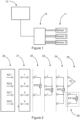
- FIG 1 a schematic view of a part of a process control system according to an embodiment of the present disclosure is shown.
- the process control system comprises an I/O system 10 to which different sensors/field devices 11 are connected.
- a field technician When doing commissioning, a field technician usually has a signal list of connected field devices/sensor units 11, a topology of the process control system and an engineering tool 12 executed on a computing unit for configuring the process control system or parts of it.
- a field technician usually has a signal list of connected field devices/sensor units 11, a topology of the process control system and an engineering tool 12 executed on a computing unit for configuring the process control system or parts of it.
- ABB Ability System 800xA Select I/O which is generally known to the person skilled in the art.
- a signal conditioning module (SCM) 20 is shown which is connected to a terminal block unit 21 comprising four connection ports C1, C2, C3, C4 connectable with an analog sensor device, wherein the sensor device to be determined may be a 2-wire connection sensor device 22, a 3-wire connection sensor device 23, or a 4-wire connection sensor device 24.
- SCM signal conditioning module
- the sensors that may be connected to the terminal block unit 21 are shown side by side in figure 2 . Also shown are the preferred connection ports for the 2-/3-/4-wire sensor devices in the preferred embodiment.
- the output side of the terminal block unit 21 is connected with the respective input side of the signal conditioning module 20, wherein in the shown preferred embodiment the connection ports of the terminal block unit 21 is connected with the ports of signal conditioning module 20 as follows: C1 with X2:1, C2 with X2:5, C3 with X2:7 and C4 with X2:9.
- connection ports of the terminal block unit 21 are preferably configures as follows: C1 and C3 for receiving the wires of a 2-wire sensor/field device; C1, C2 and C3 for receiving the wires of a 3-wire sensor/field device; C1, C2, C3 and C4 for receiving the wires of a 4-wire sensor/field device.
- a step a) it is detected whether a predefined resistance value is present for a 2-wire connection sensor device 22 at the connection ports C1 and C3 of the terminal block unit 21 provided for a 2-wire connection sensor device.
- step a) If in step a), a predefined resistance value for a 2-wire connection sensor device 22 is detected, it is further detected in a step b) whether a predefined resistance value is present for a 3-wire connection sensor device 23 at the connection ports C1, C2 and C3 of the terminal block unit 21 provided for a 3-wire connection sensor device.
- step b If in step b), no predefined resistance value for a 3-wire connection sensor device is detected it is determined that a 2-wire connection sensor device 22 is connected to the terminal block unit 21.
- step b) If in step b), a predefined resistance value for a 3-wire connection sensor device 23 is detected, it is further detected in a step c) whether a predefined resistance value between two predefined pairs of connection ports of the terminal block unit is provided.
- the pairs are C1-C2 (X2:1-X2:5) and C3-C4 (X2:7-X2:9).
- step c If in step c), only between one of the two predefined pairs of connection ports of the terminal block unit 21, here e.g. C1-C2 (X2:1-X2:5), a predefined resistance value is detected, it is determined that a 3-wire connection sensor device 23 is connected to the terminal block unit 21.
- a predefined resistance value is detected, it is determined that a 4-wire connection sensor device 24 is connected to the terminal block unit 21.
- the analog sensor device 22, 23, 24 is a resistance temperature detector (RTD) device or a thermocouple (TC) device 25.
- RTD resistance temperature detector
- TC thermocouple
- the above described method further comprises: detecting whether a thermocouple device 25 is connected to the terminal block unit 21 by executing a loop supervision test and, in case, the loop supervision test is successful determining that a thermocouple device 25 is connected to the terminal block unit 21.
- the resistance temperature detector device 22, 23, 24 and/or the thermocouple device 25 may be a compensated resistance temperature detector device, wherein it is preferred that it comprises a cold junction compensation, an internal compensation or a fixed compensation by parameter.
- the method further comprises: detecting a cold junction temperature of the compensated resistance temperature detector device; in case, the detected cold junction temperature is within a predefined temperature range, determine that the resistance temperature detector device comprises a cold junction compensation; in case, the detected cold junction temperature is not within a predefined temperature range, determine that the resistance temperature detector device comprises an internal compensation or a fixed compensation by parameter.
- the determined information of the sensor device 22 to 26 are provided to the engineering tool 12 which is configured to merge the determined information of the sensor device with provided signal list data comprising information of sensor devices used in the process control system.
- the determined information may then be provided to the engineering tool 12 which merges the detected information on wiring and sensor category with the signal list data. A commissioner is then able to review the consolidated list. Finally, the engineering tool 12 may also create a configuration for the I/O System based on the detected information.
Landscapes
- Physics & Mathematics (AREA)
- General Physics & Mathematics (AREA)
- Nonlinear Science (AREA)
- Engineering & Computer Science (AREA)
- Computer Networks & Wireless Communication (AREA)
- Signal Processing (AREA)
- Arrangements For Transmission Of Measured Signals (AREA)
Abstract
Description
- The present invention relates to a method for determining the type of an analog sensor device in a process control system, a corresponding system and a corresponding computer program element.
- Process control systems are generally known in the prior art. Process control systems comprise several different hardware units, for example, at least one I/O module with several signal conditioning units, a terminal block unit, a power source, a communication interface unit and a control unit. Process control systems are used among others to control complex production plants, e.g. in process industry or automobile industry. For example, such a process control system was developed by the applicant under the type designation ABB Ability System 800xA Select I/O. When doing commissioning of a process control system and instrumentation the field technician usually has a signal list of connected field devices and sensor units, a topology of the process control system and an engineering tool executed on a computing unit for configuring the process control system or parts of it.
- As of today, it is possible to easily integrate field devices, sensors or actuators into such a process control system that have digital communication capabilities, such as field devices that have HART communication, since the corresponding information can be easily read out from such field devices. However, more simple field devices or sensors, such as so called thermocouple, resistance temperature detectors, usually such no digital information is available.
- It has now become apparent that there is a further need to provide an easy way to commission field devices or sensors that do not have digital communication capabilities. In particular, a simple way to commission temperature sensors, which are typically of a simpler design, should be provided.
- In view of the above, it is an object of the present invention to provide an easy way to commission field devices or sensors that do not have digital communication capabilities. In particular, it is an object of the present invention to provide a simple way to commission temperature sensors, which are typically of a simpler design.
- These and other objects, which become apparent upon reading the following description, are solved by the subject matter of the independent claims. The dependent claims refer to preferred embodiments of the invention.
- According to an aspect of the present disclosure, a method for determining the type of an analog sensor/field device in a process control system is provided comprising at least a terminal block unit comprising four connection ports connectable with an analog sensor device, wherein the sensor device to be determined is a 2-wire connection sensor device, a 3-wire connection sensor device, or a 4-wire connection sensor device, the method comprising the following steps:
- a) detecting whether a predefined resistance value is present for a 2-wire connection sensor device at the connection ports of the terminal block unit provided for the 2-wire connection sensor device;
- b) in case, a predefined resistance value for a 2-wire connection sensor is detected in step a), further detecting whether a predefined resistance value is present for a 3-wire connection sensor device at the connection ports of the terminal block unit provided for the 3-wire connection sensor device;
in case, no predefined resistance value for a 3-wire connection sensor device is detected in step b) determine that a 2-wire connection sensor device is connected to the terminal block unit; - c) in case, a predefined resistance value for a 3-wire connection sensor device is detected in step b), further detecting whether a predefined resistance value between two predefined pairs of connection ports of the terminal block unit is provided;
- d) in case, only between one of the two predefined pairs of connection ports of the terminal block unit a predefined resistance value is detected in step c), determine that a 3-wire connection sensor device is connected to the terminal block unit;
in case, between two of the two predefined pairs of connection ports of the terminal block unit a predefined resistance value is detected in step c), determine that a 4-wire connection sensor device is connected to the terminal block unit. - By means of the present disclosure, the manual effort for the commissioner and the possibility for faults during manual configuration can be reduced. Notably, it is not essential in which order the respective steps are carried out, i.e. the above-mentioned steps can be carried out in any order. The same applies to the optional steps explained in the following.
- In an embodiment of the method, the analog sensor device is a resistance temperature detector (RTD) device or a thermocouple (TC) device.
- In an embodiment of the method, the method further comprises: detecting whether a thermocouple device is connected to the terminal block unit by executing a loop supervision test and, in case, the loop supervision test is successful determining that a thermocouple device is connected to the terminal block unit. As described above, the detection and determination of the resistance temperature detector devices is based on the respective resistance values. With respect to the thermocouple devices, on the other hand, the voltage values are preferably used for detection and determination of the thermocouple devises, as they are used in the loop supervision test.
- In an embodiment of the method, the resistance temperature detector device and/or the thermocouple device is a compensated resistance temperature detector device, wherein it comprises a cold junction compensation, an internal compensation or a fixed compensation by parameter.
- In an embodiment of the method, the method further comprises:
- detecting a cold junction temperature of the compensated resistance temperature detector device;
- in case, the detected cold junction temperature is within a predefined temperature range, determine that the resistance temperature detector device comprises a cold junction compensation;
- in case, the detected cold junction temperature is not within a predefined temperature range, determine that the resistance temperature detector device comprises an internal compensation or a fixed compensation by parameter.
- In an embodiment of the method, the determined information of the sensor device are provided to a computing unit which is configured to merge the determined information of the sensor device with provided signal list data comprising information of sensor devices used in the process control system.
- In an embodiment of the method, the computing unit is configured to provided configuration data for process control system based on the merged information of the sensor device and the signal list data.
- According to a further aspect of the present disclosure, a system for determining the type of an analog sensor device in a process control system is provided comprising at least a terminal block unit comprising four connection ports connectable with an analog sensor device, wherein the sensor device to be determined is a 2-wire connection sensor device, a 3-wire connection sensor device, or a 4-wire connection sensor device, comprising:
- a) a detection unit configured to detect whether a predefined resistance value is present for a 2-wire connection sensor device at the connection ports of the terminal block unit provided for the 2-wire connection sensor device;
- b) a detection unit configured to further detect whether a predefined resistance value is present for a 3-wire connection sensor device at the connection ports of the terminal block unit provided for the 3-wire connection sensor device, in case, a predefined resistance value for a 2-wire connection sensor is detected in step a);
- c) a determination unit configured to determine that a 2-wire connection sensor device is connected to the terminal block unit, in case, no predefined resistance value for a 3-wire connection sensor device is detected in step b);
a detection unit configured to further detect whether a predefined resistance value between two predefined pairs of connection ports of the terminal block unit is provided, in case, a predefined resistance value for a 3-wire connection sensor device is detected in step b); - d) a determination unit configured to determine that a 3-wire connection sensor device is connected to the terminal block unit, in case, only between one of the two predefined pairs of connection ports of the terminal block unit a predefined resistance value is detected in step c); a determination unit configured to determine that a 4-wire connection sensor device is connected to the terminal block unit, in case, between two of the two predefined pairs of connection ports of the terminal block unit a predefined resistance value is detected in step c).
- In an embodiment of the system, the analog sensor device is a resistance temperature detector (RTD) device or a thermocouple (TC) device.
- In an embodiment of the system, the system is further comprising: a determination unit configured to determine whether a thermocouple device is connected to the terminal block unit by executing a loop supervision test and, in case, the loop supervision test is successful determining that a thermocouple device is connected to the terminal block unit.
- In an embodiment of the system, the resistance temperature detector device is a compensated resistance temperature detector device, wherein it comprises a cold junction compensation, an internal compensation or a fixed compensation by parameter.
- In an embodiment of the system, the system is further comprising:
- a detection unit configured to detect a cold junction temperature of the compensated resistance temperature detector device;
- a determination unit configured to determine that the resistance temperature detector device comprises a cold junction compensation, in case, the detected cold junction temperature is within a predefined temperature range;
- a determination unit configured to determine that the resistance temperature detector device comprises an internal compensation or a fixed compensation by parameter, in case, the detected cold junction temperature is not within a predefined temperature range.
- In an embodiment of the system, the system is further comprising: a providing unit configured to provide the determined information of the sensor device to a computing unit, which is configured to merge the determined information of the sensor device with provided signal list data comprising information of sensor devices used in the process control system.
- In an embodiment of the system, the computing unit is configured to provide configuration data for process control system based on the merged information of the sensor device and the signal list data.
- According to a further aspect of the present disclosure, a computer program element is provided with instructions, which, when executed on computing devices of a computing environment, is configured to carry out the steps of the method as explained above in a system as explained above.
- In the following, the present disclosure is described exemplarily with reference to the enclosed figures, in which
- Figure 1
- shows a schematic view of a part of a process control system according to an embodiment of the present disclosure; and
- Figure 2
- shows a schematic view of a signal conditioning unit (SCM) to which a terminal block unit is connected comprising four connection ports connectable with an analog sensor device.
- In
figure 1 , a schematic view of a part of a process control system according to an embodiment of the present disclosure is shown. The process control system comprises an I/O system 10 to which different sensors/field devices 11 are connected. When doing commissioning, a field technician usually has a signal list of connected field devices/sensor units 11, a topology of the process control system and anengineering tool 12 executed on a computing unit for configuring the process control system or parts of it. With regard to the general structure and the basic functions of such a process control system, reference can be made by way of example to the publications of the applicant on the ABB Ability System 800xA Select I/O, which is generally known to the person skilled in the art. - The preferred method for determining the type of an analog sensor device in a process control system is explained in the following with respect to
figure 2 . Infigure 2 a signal conditioning module (SCM) 20 is shown which is connected to aterminal block unit 21 comprising four connection ports C1, C2, C3, C4 connectable with an analog sensor device, wherein the sensor device to be determined may be a 2-wireconnection sensor device 22, a 3-wireconnection sensor device 23, or a 4-wireconnection sensor device 24. - For better illustration, the sensors that may be connected to the
terminal block unit 21 are shown side by side infigure 2 . Also shown are the preferred connection ports for the 2-/3-/4-wire sensor devices in the preferred embodiment. For example, the output side of theterminal block unit 21 is connected with the respective input side of thesignal conditioning module 20, wherein in the shown preferred embodiment the connection ports of theterminal block unit 21 is connected with the ports ofsignal conditioning module 20 as follows: C1 with X2:1, C2 with X2:5, C3 with X2:7 and C4 with X2:9. The connection ports of theterminal block unit 21 are preferably configures as follows: C1 and C3 for receiving the wires of a 2-wire sensor/field device; C1, C2 and C3 for receiving the wires of a 3-wire sensor/field device; C1, C2, C3 and C4 for receiving the wires of a 4-wire sensor/field device. - In a step a), it is detected whether a predefined resistance value is present for a 2-wire
connection sensor device 22 at the connection ports C1 and C3 of theterminal block unit 21 provided for a 2-wire connection sensor device. - If in step a), a predefined resistance value for a 2-wire
connection sensor device 22 is detected, it is further detected in a step b) whether a predefined resistance value is present for a 3-wireconnection sensor device 23 at the connection ports C1, C2 and C3 of theterminal block unit 21 provided for a 3-wire connection sensor device. - If in step b), no predefined resistance value for a 3-wire connection sensor device is detected it is determined that a 2-wire
connection sensor device 22 is connected to theterminal block unit 21. - If in step b), a predefined resistance value for a 3-wire
connection sensor device 23 is detected, it is further detected in a step c) whether a predefined resistance value between two predefined pairs of connection ports of the terminal block unit is provided. In the preferred embodiment, the pairs are C1-C2 (X2:1-X2:5) and C3-C4 (X2:7-X2:9). - If in step c), only between one of the two predefined pairs of connection ports of the
terminal block unit 21, here e.g. C1-C2 (X2:1-X2:5), a predefined resistance value is detected, it is determined that a 3-wireconnection sensor device 23 is connected to theterminal block unit 21. - If in strep c), between two of the two predefined pairs of connection ports of the terminal block unit, here e.g. C1-C2 (X2:1-X2:5) and C3-C4 (X2:7-X2:9), a predefined resistance value is detected, it is determined that a 4-wire
connection sensor device 24 is connected to theterminal block unit 21. - It has to be pointed out that the order of the above explained steps is not essential, i.e. the explained steps can be carried out in any order. The same applies to the optional steps explained in the following.
- In this respect, it is preferred that the
analog sensor device device 25. - In this respect, it is further preferred that the above described method further comprises: detecting whether a
thermocouple device 25 is connected to theterminal block unit 21 by executing a loop supervision test and, in case, the loop supervision test is successful determining that athermocouple device 25 is connected to theterminal block unit 21. - Notably, the resistance
temperature detector device thermocouple device 25 may be a compensated resistance temperature detector device, wherein it is preferred that it comprises a cold junction compensation, an internal compensation or a fixed compensation by parameter. In this respect, it is preferred that the method further comprises: detecting a cold junction temperature of the compensated resistance temperature detector device; in case, the detected cold junction temperature is within a predefined temperature range, determine that the resistance temperature detector device comprises a cold junction compensation; in case, the detected cold junction temperature is not within a predefined temperature range, determine that the resistance temperature detector device comprises an internal compensation or a fixed compensation by parameter. - The determined information of the
sensor device 22 to 26 are provided to theengineering tool 12 which is configured to merge the determined information of the sensor device with provided signal list data comprising information of sensor devices used in the process control system. - As a result, it is preferred with the present disclosure to be able to detect and determine information with respect to 2-wire RTD, 3-wire RTD, 4-wire RTD, 2-wire TC and 2-wire TC with an external CJC.
- In the following, a summary of the preferred and preferred advantages of the present disclosure is provided explained:
When doing commissioning of an I/O system and instrumentation the field technician usually has: - a signal list of connected field/sensor devices e.g. wiring information, device type, device identifier, connected sensor type, etc.
- a topology of the I/O system
- an engineering tool to configure the I/O System
- As of today, it is possible to read the actual topology from the I/O System. Also for field/sensor devices with electronics, e.g. HART compatible devices, it is possible to read out the required information for commissioning the I/O system. However, for simple field/sensor devices, e.g. thermocouple or resistance temperature detectors, usually no digital information is available. Still there are various different connections, e.g. wirings of the RTD, possible that have to be configured well in the I/O system to make it possible to read correct process information from the field device or sensor.
- By means of the present disclosure, it is possible to detect/determine the temperature sensor wiring and sensor category during startup and may provide this information to an engineering tool. By means of the following preferred sequence sensor category and wiring (2-wire RTD, 3-wire RTD, 4-wire RTD, TC with CJC) can be determined:
- (1) Configure an analog-to-digital converter (ADC) to expect a two-wire RTD.
- (2) Read data from ADC.
- (3) When reading a valid resistance, it is about a 2-/3- or 4-wire RTD
- (4) Reconfigure the ADC to expect a three-wire RTD.
- (5) Read data from ADC.
- (6) When reading a valid resistance, it is about a 3- or 4-wire RTD
- (7) Measure Wire-Resistance between X2:1 -X2:5 and X2:7-X2:9
- (8) When only X2:1-X2:5 has a valid resistance (e.g. <300 Ohm), it is determined that a 3-wire RTD is connected
- (9) When both X2:1-X2:5 and X2:-X2:9 have a valid resistance, it is determined that a 4-wire RTD is connected.
- (10) Reconfigure the ADC to expect a TC.
- (11) Execute a loop supervision test: when it is successful, a TC is determined.
- (12) Enable digital-to-analog converter (DAC) for a PT100 element.
- (13) Read the cold junction (CJ) temperature
- (14) When the cold junction temperature it is in expected range (e.g. - 40...70 °C), a CJC by external PT100 (
reference sign 26 infigure 2 ) is determined; when not we either an internal compensation or fixed compensation by parameter is determined. - The determined information may then be provided to the
engineering tool 12 which merges the detected information on wiring and sensor category with the signal list data. A commissioner is then able to review the consolidated list. Finally, theengineering tool 12 may also create a configuration for the I/O System based on the detected information. - The present disclosure has been described in conjunction with a preferred embodiment as examples as well. However, other variations can be understood and effected by those persons skilled in the art and practicing the claimed invention, from the studies of the drawings, this disclosure and the claims. Notably, in particular, the any steps presented can be performed in any order, i.e. the present invention is not limited to a specific order of these steps. Moreover, it is also not required that the different steps are performed at a certain place or at one node of a distributed system, i.e. each of the steps may be performed at a different nodes using different equipment/data processing units.
- In the claims as well as in the description the word "comprising" does not exclude other elements or steps and the indefinite article "a" or "an" does not exclude a plurality. A single element or other unit may fulfill the functions of several entities or items recited in the claims. The mere fact that certain measures are recited in the mutual different dependent claims does not indicate that a combination of these measures cannot be used in an advantageous implementation.
Claims (15)
- A method for determining the type of an analog sensor device in a process control system comprising at least a terminal block unit comprising four connection ports connectable with an analog sensor device, wherein the sensor device to be determined is a 2-wire connection sensor device, a 3-wire connection sensor device, or a 4-wire connection sensor device, the method comprising the following steps:a) detecting whether a predefined resistance value is present for a 2-wire connection sensor device at the connection ports of the terminal block unit provided for the 2-wire connection sensor device;b) in case, a predefined resistance value for a 2-wire connection sensor is detected in step a), further detecting whether a predefined resistance value is present for a 3-wire connection sensor device at the connection ports of the terminal block unit provided for the 3-wire connection sensor device;c) in case, no predefined resistance value for a 3-wire connection sensor device is detected in step b) determine that a 2-wire connection sensor device is connected to the terminal block unit; in case, a predefined resistance value for a 3-wire connection sensor device is detected in step b), further detecting whether a predefined resistance value between two predefined pairs of connection ports of the terminal block unit is provided;d) in case, only between one of the two predefined pairs of connection ports of the terminal block unit a predefined resistance value is detected in step c), determine that a 3-wire connection sensor device is connected to the terminal block unit;in case, between two of the two predefined pairs of connection ports of the terminal block unit a predefined resistance value is detected in step c), determine that a 4-wire connection sensor device is connected to the terminal block unit.
- Method according to claim 1, wherein the analog sensor device is a resistance temperature detector (RTD) device or a thermocouple (TC) device.
- Method according to claim 2, wherein the method further comprises:
detecting whether a thermocouple device is connected to the terminal block unit by executing a loop supervision test and, in case, the loop supervision test is successful determining that a thermocouple device is connected to the terminal block unit. - Method according to claim 2, wherein the resistance temperature detector device is a compensated resistance temperature detector device, wherein it comprises a cold junction compensation, an internal compensation or a fixed compensation by parameter.
- Method according to claim 4, wherein the method further comprises:detecting a cold junction temperature of the compensated resistance temperature detector device;in case, the detected cold junction temperature is within a predefined temperature range, determine that the resistance temperature detector device comprises a cold junction compensation;in case, the detected cold junction temperature is not within a predefined temperature range, determine that the resistance temperature detector device comprises an internal compensation or a fixed compensation by parameter.
- Method according to any one of the preceding claims, wherein the determined information of the sensor device are provided to a computing unit which is configured to merge the determined information of the sensor device with provided signal list data comprising information of sensor devices used in the process control system.
- Method according to claim 6, wherein the computing unit is configured to provided configuration data for process control system based on the merged information of the sensor device and the signal list data.
- System for determining the type of an analog sensor device in a process control system comprising at least a terminal block unit comprising four connection ports connectable with an analog sensor device, wherein the sensor device to be determined is a 2-wire connection sensor device, a 3-wire connection sensor device, or a 4-wire connection sensor device, comprising:a) a detection unit configured to detect whether a predefined resistance value is present for a 2-wire connection sensor device at the connection ports of the terminal block unit provided for the 2-wire connection sensor device;b) a detection unit configured to further detect whether a predefined resistance value is present for a 3-wire connection sensor device at the connection ports of the terminal block unit provided for the 3-wire connection sensor device, in case, a predefined resistance value for a 2-wire connection sensor is detected in step a);c) a determination unit configured to determine that a 2-wire connection sensor device is connected to the terminal block unit, in case, no predefined resistance value for a 3-wire connection sensor device is detected in step b);
a detection unit configured to further detect whether a predefined resistance value between two predefined pairs of connection ports of the terminal block unit is provided, in case, a predefined resistance value for a 3-wire connection sensor device is detected in step b);d) a determination unit configured to determine that a 3-wire connection sensor device is connected to the terminal block unit, in case, only between one of the two predefined pairs of connection ports of the terminal block unit a predefined resistance value is detected in step c);
a determination unit configured to determine that a 4-wire connection sensor device is connected to the terminal block unit, in case, between two of the two predefined pairs of connection ports of the terminal block unit a predefined resistance value is detected in step c). - System according to claim 8, wherein the analog sensor device is a resistance temperature detector (RTD) device or a thermocouple (TC) device.
- System according to claim 9, further comprising: a determination unit configured to determine whether a thermocouple device is connected to the terminal block unit by executing a loop supervision test and, in case, the loop supervision test is successful determining that a thermocouple device is connected to the terminal block unit.
- System according to claim 9, wherein the resistance temperature detector device is a compensated resistance temperature detector device, wherein it comprises a cold junction compensation, an internal compensation or a fixed compensation by parameter.
- System according to claim 11, further comprising:a detection unit configured to detect a cold junction temperature of the compensated resistance temperature detector device;a determination unit configured to determine that the resistance temperature detector device comprises a cold junction compensation,in case, the detected cold junction temperature is within a predefined temperature range;a determination unit configured to determine that the resistance temperature detector device comprises an internal compensation or a fixed compensation by parameter, in case, the detected cold junction temperature is not within a predefined temperature range.
- System according to any one of claims 8 to 12, further comprising a providing unit configured to provide the determined information of the sensor device to a computing unit, which is configured to merge the determined information of the sensor device with provided signal list data comprising information of sensor devices used in the process control system.
- System according to claim 13, wherein the computing unit is configured to provide configuration data for process control system based on the merged information of the sensor device and the signal list data.
- Computer program element with instructions, which, when executed on computing devices of a computing environment, is configured to carry out the steps of the method according to any one of the claims 1 to 7 in a system according any one of claims 8 to 14.
Priority Applications (3)
| Application Number | Priority Date | Filing Date | Title |
|---|---|---|---|
| EP22158306.5A EP4235124A1 (en) | 2022-02-23 | 2022-02-23 | Method for determining sensor types and sensor wiring |
| CN202310148746.6A CN116642601A (en) | 2022-02-23 | 2023-02-22 | Methods for Determining Sensor Type and Sensor Wiring |
| US18/173,138 US12618719B2 (en) | 2022-02-23 | 2023-02-23 | Method for determining sensor types and sensor wiring |
Applications Claiming Priority (1)
| Application Number | Priority Date | Filing Date | Title |
|---|---|---|---|
| EP22158306.5A EP4235124A1 (en) | 2022-02-23 | 2022-02-23 | Method for determining sensor types and sensor wiring |
Publications (1)
| Publication Number | Publication Date |
|---|---|
| EP4235124A1 true EP4235124A1 (en) | 2023-08-30 |
Family
ID=80978997
Family Applications (1)
| Application Number | Title | Priority Date | Filing Date |
|---|---|---|---|
| EP22158306.5A Pending EP4235124A1 (en) | 2022-02-23 | 2022-02-23 | Method for determining sensor types and sensor wiring |
Country Status (2)
| Country | Link |
|---|---|
| EP (1) | EP4235124A1 (en) |
| CN (1) | CN116642601A (en) |
Citations (2)
| Publication number | Priority date | Publication date | Assignee | Title |
|---|---|---|---|---|
| US7658539B2 (en) * | 2006-12-04 | 2010-02-09 | Rosemount Inc. | Temperature sensor configuration detection in process variable transmitter |
| US10135470B2 (en) * | 2017-03-16 | 2018-11-20 | Honeywell International Inc. | System and method to auto-configure a transmitter for a sensor |
Family Cites Families (2)
| Publication number | Priority date | Publication date | Assignee | Title |
|---|---|---|---|---|
| DE102020105475A1 (en) * | 2019-03-27 | 2020-10-01 | Turck Holding Gmbh | Temperature measuring device with independent measuring probe recognition |
| CN111721445B (en) * | 2020-06-16 | 2022-03-11 | 西门子传感器与通讯有限公司 | Method for identifying type of sensor connected with transmitter and transmitter |
-
2022
- 2022-02-23 EP EP22158306.5A patent/EP4235124A1/en active Pending
-
2023
- 2023-02-22 CN CN202310148746.6A patent/CN116642601A/en active Pending
Patent Citations (2)
| Publication number | Priority date | Publication date | Assignee | Title |
|---|---|---|---|---|
| US7658539B2 (en) * | 2006-12-04 | 2010-02-09 | Rosemount Inc. | Temperature sensor configuration detection in process variable transmitter |
| US10135470B2 (en) * | 2017-03-16 | 2018-11-20 | Honeywell International Inc. | System and method to auto-configure a transmitter for a sensor |
Also Published As
| Publication number | Publication date |
|---|---|
| US20230266176A1 (en) | 2023-08-24 |
| CN116642601A (en) | 2023-08-25 |
Similar Documents
| Publication | Publication Date | Title |
|---|---|---|
| US8311778B2 (en) | Industrial process control transmitter with multiple sensors | |
| EP2527854B1 (en) | Systems and methods for determining electrical faults | |
| RU2328763C2 (en) | Transducer of process control circuit signal | |
| EP2467939B1 (en) | Detection and compensation of multiplexer leakage current | |
| CN202694136U (en) | Multichannel thermal control system testing equipment | |
| US8924600B2 (en) | Programmable universal IO interface | |
| CN113503985B (en) | Self-adaptive distributed intelligent measurement node of temperature sensor | |
| CA2899042A1 (en) | Programmable interface circuit for coupling field devices to process controllers | |
| KR20140111991A (en) | Multichannel thermocouple compensation for three dimensional temperature gradient | |
| Anderson | The new current loop: An instrumentation and measurement circuit topology | |
| CN105301995A (en) | Analog signal acquisition circuit | |
| EP4235124A1 (en) | Method for determining sensor types and sensor wiring | |
| CN208488188U (en) | Multi-channel temperature sensor detection device used in nuclear power plants | |
| US20120299598A1 (en) | Systems and Methods for Determining Electrical Ground Faults | |
| US12618719B2 (en) | Method for determining sensor types and sensor wiring | |
| CN114414078B (en) | Cold end temperature estimation method of multichannel temperature acquisition system based on bilinear interpolation | |
| RU2670251C2 (en) | Infrared sensor | |
| GB2560021A (en) | Self-configuring electronic driver for remote instrumentation | |
| Anderson | Your successor to the Wheatstone bridge? NASA'S Anderson Loop | |
| EP2966519A1 (en) | Programmable universal io interface | |
| Pérez et al. | Experimental scope of an electrical energy consumption device based on multi-microprocessors, local printed circuit boards and Internet of Things (IoT) | |
| JP3937364B2 (en) | Voltage / resistance generator | |
| CN205049891U (en) | Analog signal acquisition circuit | |
| RU2196307C2 (en) | Procedure of diagnostics of temperature measuring circuits | |
| KR100275568B1 (en) | Snap detecting method for temperature measurement sensor |
Legal Events
| Date | Code | Title | Description |
|---|---|---|---|
| PUAI | Public reference made under article 153(3) epc to a published international application that has entered the european phase |
Free format text: ORIGINAL CODE: 0009012 |
|
| STAA | Information on the status of an ep patent application or granted ep patent |
Free format text: STATUS: THE APPLICATION HAS BEEN PUBLISHED |
|
| AK | Designated contracting states |
Kind code of ref document: A1 Designated state(s): AL AT BE BG CH CY CZ DE DK EE ES FI FR GB GR HR HU IE IS IT LI LT LU LV MC MK MT NL NO PL PT RO RS SE SI SK SM TR |
|
| STAA | Information on the status of an ep patent application or granted ep patent |
Free format text: STATUS: REQUEST FOR EXAMINATION WAS MADE |
|
| 17P | Request for examination filed |
Effective date: 20240228 |
|
| RBV | Designated contracting states (corrected) |
Designated state(s): AL AT BE BG CH CY CZ DE DK EE ES FI FR GB GR HR HU IE IS IT LI LT LU LV MC MK MT NL NO PL PT RO RS SE SI SK SM TR |
|
| STAA | Information on the status of an ep patent application or granted ep patent |
Free format text: STATUS: EXAMINATION IS IN PROGRESS |
|
| 17Q | First examination report despatched |
Effective date: 20241023 |