EP4234962A2 - Getreidebehältersystem und verfahren zur installation einer externen versteifung an einer seitenwand eines getreidebehälters - Google Patents
Getreidebehältersystem und verfahren zur installation einer externen versteifung an einer seitenwand eines getreidebehälters Download PDFInfo
- Publication number
- EP4234962A2 EP4234962A2 EP23177265.8A EP23177265A EP4234962A2 EP 4234962 A2 EP4234962 A2 EP 4234962A2 EP 23177265 A EP23177265 A EP 23177265A EP 4234962 A2 EP4234962 A2 EP 4234962A2
- Authority
- EP
- European Patent Office
- Prior art keywords
- sidewall
- grain bin
- stiffener
- feature
- threaded end
- Prior art date
- Legal status (The legal status is an assumption and is not a legal conclusion. Google has not performed a legal analysis and makes no representation as to the accuracy of the status listed.)
- Granted
Links
Images











Classifications
-
- E—FIXED CONSTRUCTIONS
- E04—BUILDING
- E04H—BUILDINGS OR LIKE STRUCTURES FOR PARTICULAR PURPOSES; SWIMMING OR SPLASH BATHS OR POOLS; MASTS; FENCING; TENTS OR CANOPIES, IN GENERAL
- E04H7/00—Construction or assembling of bulk storage containers employing civil engineering techniques in situ or off the site
- E04H7/22—Containers for fluent solids, e.g. silos, bunkers; Supports therefor
-
- E—FIXED CONSTRUCTIONS
- E04—BUILDING
- E04H—BUILDINGS OR LIKE STRUCTURES FOR PARTICULAR PURPOSES; SWIMMING OR SPLASH BATHS OR POOLS; MASTS; FENCING; TENTS OR CANOPIES, IN GENERAL
- E04H7/00—Construction or assembling of bulk storage containers employing civil engineering techniques in situ or off the site
- E04H7/22—Containers for fluent solids, e.g. silos, bunkers; Supports therefor
- E04H7/24—Constructions, with or without perforated walls, depending on the use of specified materials
- E04H7/30—Constructions, with or without perforated walls, depending on the use of specified materials mainly of metal
-
- B—PERFORMING OPERATIONS; TRANSPORTING
- B65—CONVEYING; PACKING; STORING; HANDLING THIN OR FILAMENTARY MATERIAL
- B65D—CONTAINERS FOR STORAGE OR TRANSPORT OF ARTICLES OR MATERIALS, e.g. BAGS, BARRELS, BOTTLES, BOXES, CANS, CARTONS, CRATES, DRUMS, JARS, TANKS, HOPPERS, FORWARDING CONTAINERS; ACCESSORIES, CLOSURES, OR FITTINGS THEREFOR; PACKAGING ELEMENTS; PACKAGES
- B65D88/00—Large containers
- B65D88/02—Large containers rigid
- B65D88/06—Large containers rigid cylindrical
- B65D88/08—Large containers rigid cylindrical with a vertical axis
-
- B—PERFORMING OPERATIONS; TRANSPORTING
- B65—CONVEYING; PACKING; STORING; HANDLING THIN OR FILAMENTARY MATERIAL
- B65D—CONTAINERS FOR STORAGE OR TRANSPORT OF ARTICLES OR MATERIALS, e.g. BAGS, BARRELS, BOTTLES, BOXES, CANS, CARTONS, CRATES, DRUMS, JARS, TANKS, HOPPERS, FORWARDING CONTAINERS; ACCESSORIES, CLOSURES, OR FITTINGS THEREFOR; PACKAGING ELEMENTS; PACKAGES
- B65D90/00—Component parts, details or accessories for large containers
- B65D90/02—Wall construction
- B65D90/027—Corrugated or zig-zag structures; Folded plate
-
- F—MECHANICAL ENGINEERING; LIGHTING; HEATING; WEAPONS; BLASTING
- F16—ENGINEERING ELEMENTS AND UNITS; GENERAL MEASURES FOR PRODUCING AND MAINTAINING EFFECTIVE FUNCTIONING OF MACHINES OR INSTALLATIONS; THERMAL INSULATION IN GENERAL
- F16B—DEVICES FOR FASTENING OR SECURING CONSTRUCTIONAL ELEMENTS OR MACHINE PARTS TOGETHER, e.g. NAILS, BOLTS, CIRCLIPS, CLAMPS, CLIPS OR WEDGES; JOINTS OR JOINTING
- F16B33/00—Features common to bolt and nut
- F16B33/004—Sealing; Insulation
-
- F—MECHANICAL ENGINEERING; LIGHTING; HEATING; WEAPONS; BLASTING
- F16—ENGINEERING ELEMENTS AND UNITS; GENERAL MEASURES FOR PRODUCING AND MAINTAINING EFFECTIVE FUNCTIONING OF MACHINES OR INSTALLATIONS; THERMAL INSULATION IN GENERAL
- F16B—DEVICES FOR FASTENING OR SECURING CONSTRUCTIONAL ELEMENTS OR MACHINE PARTS TOGETHER, e.g. NAILS, BOLTS, CIRCLIPS, CLAMPS, CLIPS OR WEDGES; JOINTS OR JOINTING
- F16B33/00—Features common to bolt and nut
- F16B33/02—Shape of thread; Special thread-forms
-
- F—MECHANICAL ENGINEERING; LIGHTING; HEATING; WEAPONS; BLASTING
- F16—ENGINEERING ELEMENTS AND UNITS; GENERAL MEASURES FOR PRODUCING AND MAINTAINING EFFECTIVE FUNCTIONING OF MACHINES OR INSTALLATIONS; THERMAL INSULATION IN GENERAL
- F16B—DEVICES FOR FASTENING OR SECURING CONSTRUCTIONAL ELEMENTS OR MACHINE PARTS TOGETHER, e.g. NAILS, BOLTS, CIRCLIPS, CLAMPS, CLIPS OR WEDGES; JOINTS OR JOINTING
- F16B35/00—Screw-bolts; Stay-bolts; Screw-threaded studs; Screws; Set screws
- F16B35/04—Screw-bolts; Stay-bolts; Screw-threaded studs; Screws; Set screws with specially-shaped head or shaft in order to fix the bolt on or in an object
- F16B35/041—Specially-shaped shafts
- F16B35/042—Specially-shaped shafts for retention or rotation by a tool, e.g. of polygonal cross-section
-
- F—MECHANICAL ENGINEERING; LIGHTING; HEATING; WEAPONS; BLASTING
- F16—ENGINEERING ELEMENTS AND UNITS; GENERAL MEASURES FOR PRODUCING AND MAINTAINING EFFECTIVE FUNCTIONING OF MACHINES OR INSTALLATIONS; THERMAL INSULATION IN GENERAL
- F16B—DEVICES FOR FASTENING OR SECURING CONSTRUCTIONAL ELEMENTS OR MACHINE PARTS TOGETHER, e.g. NAILS, BOLTS, CIRCLIPS, CLAMPS, CLIPS OR WEDGES; JOINTS OR JOINTING
- F16B43/00—Washers or equivalent devices; Other devices for supporting bolt-heads or nuts
- F16B43/001—Washers or equivalent devices; Other devices for supporting bolt-heads or nuts for sealing or insulation
-
- F—MECHANICAL ENGINEERING; LIGHTING; HEATING; WEAPONS; BLASTING
- F16—ENGINEERING ELEMENTS AND UNITS; GENERAL MEASURES FOR PRODUCING AND MAINTAINING EFFECTIVE FUNCTIONING OF MACHINES OR INSTALLATIONS; THERMAL INSULATION IN GENERAL
- F16B—DEVICES FOR FASTENING OR SECURING CONSTRUCTIONAL ELEMENTS OR MACHINE PARTS TOGETHER, e.g. NAILS, BOLTS, CIRCLIPS, CLAMPS, CLIPS OR WEDGES; JOINTS OR JOINTING
- F16B5/00—Joining sheets or plates, e.g. panels, to one another or to strips or bars parallel to them
- F16B5/02—Joining sheets or plates, e.g. panels, to one another or to strips or bars parallel to them by means of fastening members using screw-thread
- F16B5/0275—Joining sheets or plates, e.g. panels, to one another or to strips or bars parallel to them by means of fastening members using screw-thread the screw-threaded element having at least two axially separated threaded portions
-
- Y—GENERAL TAGGING OF NEW TECHNOLOGICAL DEVELOPMENTS; GENERAL TAGGING OF CROSS-SECTIONAL TECHNOLOGIES SPANNING OVER SEVERAL SECTIONS OF THE IPC; TECHNICAL SUBJECTS COVERED BY FORMER USPC CROSS-REFERENCE ART COLLECTIONS [XRACs] AND DIGESTS
- Y02—TECHNOLOGIES OR APPLICATIONS FOR MITIGATION OR ADAPTATION AGAINST CLIMATE CHANGE
- Y02A—TECHNOLOGIES FOR ADAPTATION TO CLIMATE CHANGE
- Y02A40/00—Adaptation technologies in agriculture, forestry, livestock or agroalimentary production
- Y02A40/10—Adaptation technologies in agriculture, forestry, livestock or agroalimentary production in agriculture
- Y02A40/51—Adaptation technologies in agriculture, forestry, livestock or agroalimentary production in agriculture specially adapted for storing agricultural or horticultural products
Definitions
- This disclosure relates to grain storage devices used in agriculture. More specifically and without limitation, this disclosure relates to a double ended stud bolt system and method of use for installing external stiffeners on the sidewall of grain bins.
- Grain bins are massive structures used to store bulk flowable grain products such as corn, soybeans, wheat, rice, or any other grain products or other material.
- Conventional grain bins are generally formed in a cylindrical shape with a corrugated sidewall covered by a peaked roof. Grain bins vary in height (ranging from twenty feet high to over a hundred and fifty feet high), and diameter, (ranging from eighteen feet in diameter to over a hundred and fifty feet in diameter).
- the storage capacity of modern grain bins can range anywhere from a few thousand bushels to well over a million bushels.
- Grain bins are often used to store grain for long periods of time. To ensure the stability of bulk grain during long-term storage the moisture level of the grain is closely monitored and controlled. As an example, corn is often stored within the narrow range of 13% to 16% moisture. If, however, the moisture level exceeds certain limits, the grain will likely spoil.
- An external stiffener is an elongated structural member that generally extends vertically along a grain bin sidewall. External stiffeners can themselves be formed of a plurality of layers, meaning that the external stiffeners themselves are "laminated.” These external stiffeners are generally bolted to the exterior surface of the grain bin sidewall. While these external stiffeners are successful at increasing the strength of the grain bin, these stiffeners further complicate the assembly process. In addition, attaching external stiffeners to the grain bin sidewall makes it more complicated to prevent water from entering the grain bin as water can travel between the stiffener and the sidewall and into the grain bin if not sealed properly.
- bolts used to connect a stiffener to a grain bin are inserted from the interior of the grain bin outward through the sidewall and through the stiffener thereby connecting the stiffener to the sidewall.
- the head of these bolts are sealed against the interior surface of the interior layer of the laminated sheet that forms the sidewall. Sealing the head of these bolts against the interior surface of the interior layer of the laminated sheet that forms the sidewall does not prevent water from entering the grain bin.
- Another object of the disclosure is to provide a system of connecting a stiffener to the sidewall of a grain bin that prevents water from seeping into the grain bin.
- Yet another object of the disclosure is to provide a system of connecting a stiffener to the sidewall of a grain bin that is easy to use.
- Another object of the disclosure is to provide a system of connecting a stiffener to the sidewall of a grain bin that provides a seal against the exterior surface of the sidewall of the grain bin regardless whether a gap is present between the stiffener and the sidewall.
- Yet another object of the disclosure is to provide a system of connecting a stiffener to the sidewall of a grain bin that has a long useful life.
- Another object of the disclosure is to provide a system of connecting a stiffener to the sidewall of a grain bin that is durable.
- Yet another object of the disclosure is to provide a system of connecting a stiffener to the sidewall of a grain bin that is easy to manufacture.
- Another object of the disclosure is to provide a system of connecting a stiffener to the sidewall of a grain bin that is relatively inexpensive.
- Yet another object of the disclosure is to provide a system of connecting a stiffener to the sidewall of a grain bin that has a robust design.
- Another object of the disclosure is to provide a system of connecting a stiffener to the sidewall of a grain bin that is high quality.
- Yet another object of the disclosure is to provide a system of connecting a stiffener to the sidewall of a grain bin that is easy to install.
- Another object of the disclosure is to provide a system of connecting a stiffener to the sidewall of a grain bin that can be installed using conventional equipment and tools.
- Yet another object of the disclosure is to provide a system of connecting a stiffener to the sidewall of a grain bin that reduces or prevents water from getting between the layers of a laminated sidewall.
- Another object of the disclosure is to provide a system of connecting a stiffener to the sidewall of a grain bin that reduces grain spoilage.
- Yet another object of the disclosure is to provide a system of connecting a stiffener to the sidewall of a grain bin that reduces grain bin corrosion.
- Another object of the disclosure is to provide a system of connecting a stiffener to the sidewall of a grain bin that reduces clumping of grain within a grain bin.
- Yet another object of the disclosure is to provide a system of connecting a stiffener to the sidewall of a grain bin that can be used with any grain bin.
- Another object of the disclosure is to provide a system of connecting a stiffener to the sidewall of a grain bin that can be used with any stiffener.
- Yet another object of the disclosure is to provide a system of connecting a stiffener to the sidewall of a grain bin that extends the useful life of a grain bin.
- Yet another object of the disclosure is to provide a system of connecting a stiffener to the sidewall of a grain bin that facilitates a secure connection between the sidewall of the grain bin and the stiffener.
- Yet another object of the disclosure is to provide a system of connecting a stiffener to the sidewall of a grain bin that provides a new and improved manner of assembling an externally stiffened grain bin
- a system of connecting a stiffener to the sidewall of a grain bin using a double end stud bolt having a first threaded end, a second threaded end and a feature positioned between the first end and a second end is presented.
- a sealing member is positioned over the first end of the stud bolt, which in one case is a metallic washer with an affixed compressible member, such as a rubber, plastic, composite or other washer formed of a non-metallic or other material that facilitates a seal.
- the first end of the stud bolt is inserted into a hole in the sidewall and an inner nut is placed over the first end inside the sidewall.
- the feature is pulled toward the exterior surface of the grain bin thereby causing the sealing member to form a seal with the exterior surface of the grain bin.
- the second end of the stud bolt is inserted into a hole in a stiffener and an outer nut is placed over the second end on the exterior side of the stiffener.
- the stiffener is pulled toward the exterior surface of the grain bin thereby connecting the stiffener to the grain bin.
- a double ended stud bolt system 10 (system 10) is presented that includes a stud bolt 12 that is used to install a stiffener 14 onto a sidewall 16 of a grain bin 18, as is further described herein.
- grain bin 18 may be formed of any suitable size, shape and design and is configured to hold a bulk amount of flowable material such as grain or the like materials.
- grain bin 18 is a large, generally cylindrical structure that has a curved sidewall 16.
- Sidewall 16 connects at its lower end to a foundation 20.
- Sidewall 16 connects at its upper end to a peaked roof 22.
- Sidewall 16 of grain bin 18 is formed of any suitable size, shape and design.
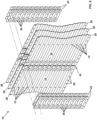
- sidewall 16 is formed of a plurality of sheets 24 of material. Sheets 24 have an upper edge 26, a lower edge 28 and side edges 30. Sheets 24 have in exterior surface 32 and interior surface 34.
- these sheets 24 are formed of corrugated material. That is, when sheets 24 are viewed from their side edge 30, the sheets 24 have a repetitive oscillating curve that smoothly transitions between rounded peaks and rounded valleys, similar to that of a sine-wave or sine-function.
- This corrugation provides strength and rigidity to the sidewall 16 however the corrugation provides a number of challenges, such as manufacturing complexities and preventing water from infiltrating the grain bin 18.
- Any other configuration of sidewall 16 and more broadly grain bin 18, is hereby contemplated for use in association with stiffener 14 and stud bolt 12.
- Sheets 24 of sidewall 16 may be formed of a single layer of material. Alternatively, to increase the strength and rigidity of the sidewall 16 a plurality of sheets 24 may be laid over one another thereby forming what is known as a "laminated" sheet 24 or sidewall 16. Laminated sheets 24 may include two, three, four, five or any other number of layers.
- sheets 24 curve slightly from side edge 30 to side edge 30 such that each sheet 24 forms a partial portion of a cylinder.
- a plurality of sheets 24 are connected together in side-to-side arrangement to form what is known as a ring 36.
- each ring 36 is formed of a plurality of sheets 24 connected together with each sheet 24 having one side edge 30 positioned inside of an adjacent sheet 24 and the opposite side edge 30 positioned outside of the other adjacent sheet 24.
- Adjacent sheets 24 are connected together using a plurality of sidewall bolts 38 that extend through the overlapping portion of adjacent sheets 24.
- rings 36 are vertically stacked to form sidewall 16. Rings 36 are stacked in such a manner that the lower edge 28 of the sheets 24 of the upper-positioned ring 36 is positioned on the outside of the upper edge 26 of the sheets 24 of the lower-positioned ring 36. The vertically adjacent sheets 24 are then connected together using a plurality of sidewall bolts 38 that extend through the overlapping portion of the vertically adjacent sheets 24.
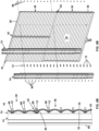
- step 40 By overlapping the vertically stacked rings 36 in this manner this forms a step 40 where the exterior surface 32 at the lower edge 28 of the upper positioned sheet 24 is spaced outward a distance "D" from the exterior surface 32 of lower positioned sheet 24.
- This distance "D” is equivalent to the thickness of sheet 24. The thicker the sheet 24, the greater the distance "D” of step 40.
- This step 40 helps to shed water running down the exterior surface 32 of sidewall 16.
- this step 40 provides a problem when attaching a stiffener 14 to the exterior surface 32 of the sidewall 16, as is further described herein.
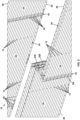
- While rings 36 are vertically stacked, to provide maximum strength, in one arrangement care is taken to offset the seams 42 formed by the overlapping sides edges 30 of adjacent sheets 24. With reference to Fig. 2 , these seams 42 are positioned in what is known as a bricklayer's pattern wherein the seams 42 of each vertically stacked ring 36 are offset a predetermined amount from the seams 42 of the ring 36 positioned immediately above and below. However any other arrangement is hereby contemplated for use. As is also shown in Fig. 2 , in one arrangement, as one example, stiffeners 14 are connected to sidewall 16 offset from seams 42.
- stiffeners 14 are attached.
- Stiffeners 14 are formed of any suitable size, shape and design and are configured to be attached to the exterior surface 32 of the sidewall 16 of grain bin 18 and provide additional strength and rigidity to sidewall 16. As such, stiffener 14 is any structural element that is affixed to the sidewall 16 of grain bin 18 that enhances the strength and/or rigidity of the sidewall 16.
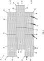
- stiffeners 14 extend a length from an upper edge 44 to a lower edge 46, which in the arrangement shown in Fig. 1 coincides with the upper edge of the upper-most ring 36 and the lower edge of the lower-most ring 36, however any other configuration is hereby contemplated for use.
- Stiffeners 14 can extend the entire length/height of sidewall 16, such as that shown in Fig. 1 , or alternatively, stiffeners 14 can extend any portion of sidewall 16. In the arrangement shown, stiffeners 14 provide strength and rigidity to grain bin 18 in-part by extending across multiple rings 36.
- stiffeners 14 have in exterior surface 48, that faces outward and away from the exterior surface of sidewall 16 of grain bin 18, and an interior surface 50 that faces inward and toward the sidewall 16 of grain bin 18.
- stiffener 14 includes a center wall 52, opposing side members 54, forward walls 56 and tabs 58.
- Center wall 52 is generally flat and planar and extends from upper edge 44 to lower edge 46, or a distance thereof.
- Center wall 52 includes a plurality of vertically spaced holes 60 positioned approximately at its center. These holes 60 are configured to receive a portion of stud bolt 12 there through to facilitate attachment of the stiffener 14 to the sidewall 16 of grain bin 18 as is further described herein.
- center wall 52 is connected to opposing side members 54.
- side members 54 are generally flat and planar and extend from upper edge 44 to lower edge 46, or a distance thereof.
- Side members 54 connect at their rearward edge 62 to the outward edge of center wall 52, and connect at their forward edge 64 to the inward edge of forward wall 56.
- Side members 54 extend outward at an angle away from one another (and away from center wall 52) as they extend from center wall 52 to forward wall 56.
- forward edges 64 of side members 54 are connected to the inward edges of forward walls 56.
- forward walls 56 are generally flat and planar and extend from upper edge 44 to lower edge 46, or a distance thereof.
- opposing forward walls 56 are positioned in approximate planar spaced relation to one another, and forward walls 56 are positioned in approximate parallel spaced relation to center wall 52.
- Forward walls 56 connect at their outward edges 66 to the forward edge of tabs 58.
- tabs 58 connect to the outward edges 66 of tabs 58.
- tabs 58 are generally flat and planar and extend from upper edge 44 to lower edge 46, or a distance thereof. In the arrangement shown, tabs 58 extend outward at an angle away from one another (and away from center wall 52 while extending toward sidewall 16) as they extend from their forward edge before terminating at their rearward edge 68.
- center wall 52, side members 54, forward walls 56 and tabs 58 form a structural element that provides additional strength and rigidity when connected the sidewall 16 of grain bin 18.
- the combination of center wall 52, side members 54, forward walls 56 and tabs 58 essentially form corrugation, like that of sidewall 16 of grain bin 18 that provides strength and rigidity.
- stiffener 14 is shown having center wall 52, side members 54, forward walls 56 and tabs 58, this is just one of countless examples for the design of stiffener 14, and any other features or combination of features are hereby contemplated for use with stiffener 14.
- stiffener 14 may be formed of a plurality of layers, or "laminated” to provide additional strength and rigidity.
- stiffeners 14 that extend the length of sidewall 16 may be formed of a plurality of sections that are connected together in end-to-end connection and/or in overlapping condition.
- stiffener 14 is attached to the exterior surface 32 of sidewall 16 of grain bin 18 by inserting a conventional sidewall bolt 38 having a head and a threaded shaft from the interior surface 34 of sidewall 16, through sidewall 16 and through a hole in stiffener 14.
- a nut is then placed on the outward end of the threaded shaft of the sidewall bolt 38 on the exterior of sidewall 16 and stiffener 14. This nut is then tightened against the exterior surface 48 of stiffener 14.
- the head of this sidewall bolt 38 seals against the interior surface 34 of sidewall 16.
- a sealing member such as a compressible washer, may be placed between the head of the sidewall bolt 38 and the interior surface 34 of sidewall 16. In this arrangement, the sealing member forms the seal between the head of sidewall bolt 38 and interior surface 34 of sidewall 16.
- This interior positioned side edge 301 may be referred to as the "leaking edge” or “seeping edge” of laminated sheet 24 of rings 36 of sidewall 16.
- Stud bolt 12 is formed of any suitable size, shape and design and is configured to tighten against the exterior surface 32 of sidewall 16 of grain bin 18 while also pulling stiffener 14 into firm engagement with the sidewall 16 of grain bin 18.
- the use of stud bolt 12 ensures that a seal is formed with the exterior surface 32 of sidewall 16 of grain bin 18 regardless of whether the interior surface 50 of stiffener 14 can be drawn tight against the exterior surface 32 of sidewall 16 of grain bin 18.
- stud bolt 12 is a generally cylindrical elongated member having a first threaded end 70 and a second threaded end 72.
- First threaded end 70 and second threaded end 72 are positioned in coaxial alignment with one another. That is, the center axis of rotation of first threaded end 70 and second threaded end 72 are in alignment with one another, despite the fact that the diameters or shapes or features of the first threaded end 70 and second threaded end 72 may differ.
- a feature 74 is positioned between the first threaded end 70 and the second threaded end 72.
- First threaded end 70 and second threaded end 72 may have the same diameter, or different diameters.
- First threaded end 70 and second threaded end 72 may have the same length, or different lengths.
- First threaded end 70 and second threaded end 72 may have the same threads, or different threads.
- Feature 74 is formed of any suitable size, shape and design. Feature 74 serves to engage the exterior surface 32 of sidewall 16 of grain bin 18 as the first threaded end 70 is tightened against the sidewall 16. Feature 74 may be formed of that same material as that of the first threaded end 70 and/or second threaded end 72 in a monolithic or unitary structure, such as being formed through a machining process or casting process or the like manufacturing process.
- feature 74 may be a separate component to the shaft formed by first threaded end 70 and second threaded end 72 that is affixed thereto by a secondary process to form a unitary member, such as through a welding process, a pinning process, a bolting process, an adhering process, a gluing process or by any other process that results in a permanent or semi-permanent connection between a separate feature 74 and the shaft formed by first threaded end 70 and second threaded end 72.
- feature 74 may be attached to the first threaded end 70 and/or the second threaded end 74 while being moveable along all or a portion of the length of the stud bolt 12. In one arrangement, this is accomplished by feature 74 being a nut or other member that is threaded over first threaded end 70 and/or second threaded end 72. Alternatively, any combination of the above is contemplated for use.
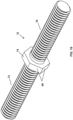
- feature 74 is formed of a hexagonal, or hex-head member that is positioned approximately in the middle of stud bolt 12 between first threaded end 70 and second threaded end 72, which are of approximately the same length, diameter and thread.
- the use of a hex-head member for feature 74 allows for the use of a conventional deep socket or wrench during the assembly process to hold or rotate the stud bolt 12.
- the length of the first threaded end 70 and second threaded end 72 vary such that feature is not positioned in the approximate middle of the stud bolt 12.
- first threaded end 70 and second threaded end 72 vary in diameter, such that one end has a larger diameter than the other end.
- first threaded end 70 and second threaded end 72 have different threads. Any other differences between the first threaded end 70 and second threaded end 72 are hereby contemplated for use.
- feature 74 is formed of as a unitary and monolithic member with the shaft formed by first threaded end 70 and second threaded end 72 such that the feature 74 is non-moveable along the length of stud bolt 12.
- feature 74 is threaded onto shaft formed by first threaded end 70 and/or second threaded end 72 or otherwise connected in a moveable manner.
- feature 74 is a separate member from the shaft formed by first threaded end 70 and/or second threaded end 72 and is affixed by a secondary process to form a unitary member, such as through a welding process, a pinning process, a bolting process, an adhering process, a gluing process or by any other process that results in a permanent or semi-permanent connection between a separate feature 74 and the shaft formed by first threaded end 70 and/or second threaded end 72
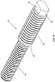
- feature 74 is formed of a step or shoulder positioned between a smaller diameter first threaded end 70 and a larger diameter second threaded end 72. Also shown in this example is a rotation member 76 positioned in the end of the second threaded end 72. Rotation member 76 is any feature or device that allows for the stud bolt 12 to be grasped and rotation to be imparted on the stud bolt 12. In the arrangement shown, as one example, rotation member 76 is generally cylindrical in shape and has a diameter slightly smaller than the diameter of the second threaded end 72. This rotation member 76 includes a pair of flat surfaces 78 on opposing sides of the rotation member 76.
- rotation member 76 can take on any other form, such as a hex-head member, a square head member, a recessed hexagonal socket, a recessed square socket, a recessed flat head feature that receives a flat head screw driver, a recessed Philips head feature that receives a Phillips head screw driver, a slot, a pair of crossed slots, or any other feature that can be used to impart rotation.
- rotation member 76 While in the arrangement shown, in Figs. 17-19 , rotation member 76 is shown as positioned on one end of the stud bolt 12, it is hereby contemplated that rotation member 76 may be placed on either end or both ends of the stud bolt 12, or along the length of stud bolt 12.
- feature 74 is formed of a generally circular or cylindrical flange member that is positioned between first threaded end 70 and second threaded end 72, with the first threaded end 70 and the second threaded end 72 having approximately the same diameter and thread. However, the second threaded end 72 is longer than the first threaded end 70 in this example.
- the feature 74 has a generally cylindrical or disc-shaped design with a pair of opposing flat surfaces 80 positioned on opposite sides of the feature 74. These flat surfaces 80 allow for a wrench or other tool to grasp the feature 74 and impart torque there on. This can be useful during the installation process to facilitate holding the stud bolt 12 in place or to impart rotation upon stud bolt 12.
- Stud bolt 12 can be formed of any other suitable size, shape and design. Stud bolt 12 is used to tighten a sealing member 82 against the exterior surface 32 and/or interior surface 34 of sidewall 16 of grain bin 18 thereby forming a seal against sidewall 16. Stud bolt 12 may be formed of any combination of any or all of the configurations or features mentioned herein.
- Sealing member 82 is formed of any suitable size, shape and design and is configured to form a seal against the exterior surface 32 and/or interior surface 34 of sidewall 16 of grain bin 18 to thereby prevent water from entering the interior of grain bin 18.
- Sealing member 82 is any device that forms a seal, such as a compressible washer, an O-ring, a gasket, a sealing adhesive layer, a compressible member, a flange gasket, or the like.
- Sealing member 82 may be formed of any compressible material that is capable of forming a seal with the exterior surface 32 and/or interior surface 34 of sidewall 16, such as rubber, plastic, composite, nylon washer, neoprene, a poly, or any other compressible material and/or combination thereof.
- sealing member 82 includes a rigid washer 84 and a compressible member 86 that fit around the first threaded end 70 of the stud bolt 12.
- rigid washer 84 and compressible member 86 are separate and unattached components.
- rigid washer 84 and compressible member 86 are adhered or connected to one another and/or formed as a single component, which reduces assembly steps and reduces the potential that the components will be unintentionally separated from one another during or prior to the installation process.
- the rigid washer 84 is eliminated and the feature 74 serves as the rigid washer 84 that forces the compressible member 86 into engagement with the exterior surface 32 and/or interior surface 34 of the sidewall 16 of grain bin 18.
- the rigid washer 84 is formed as part of the feature 74 and the compressible member 86 is either a separate piece from this combined feature 74 and rigid washer 84, or is adhered to or connected to or formed as part of this combined feature 74 and rigid washer 84.
- feature 74 is a hex-shaped, or other shaped, member like many conventional nuts with an extended flange or washer formed as part of one end of the feature 74; this feature 74 with the combined flange or washer may be formed as part of the stud bolt 12 or it may be added as a separate nut-type member that is placed on the stud bolt 12.
- feature 74 includes a recess therein, such as a groove that facilitates connection to compressible member 86, such as receiving a compressible O-ring therein or receiving a flange of a gasket therein that holds the compressible member 86 to the feature 74.
- sidewall 16 of grain bin 18 is assembled by connecting sheets, 24, which may be laminated sheets formed of a plurality of layers, in edge-to-edge alignment to form rings 36.
- sheets, 24, which may be laminated sheets formed of a plurality of layers, in edge-to-edge alignment to form rings 36.
- rings 36 are formed by inserting side sidewall bolts 38 through the sheets 24 which when tightened the head and sealing member of the sidewall bolt 38 forms a seal with the exterior surface 32 of the sheet.
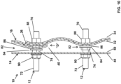
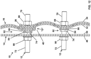
- stiffeners 14 are added to the exterior surface 32 of sidewall 16 using stud bolts 12. If stud bolts 12 are not pre-assembled with sealing member 82, which may be formed of a rigid washer 84 and a compressible member 86 thereon, the sealing member 82 is placed on the first threaded end 70 of stud bolts 12. Assembled stud bolts 12 are then installed on the sidewall 16. The first threaded end 70 of the stud bolt 12 is inserted into a hole in the sidewall 16. Next, an inner nut 88 is threaded onto the end of the first threaded end 70 of the stud bolt 12 on the inside of sidewall 16 within grain bin 18.
- the inner nut 88 is then tightened against the interior surface 34 of the sidewall 16 thereby pulling the feature 74 of the stud bolt 12 toward the exterior surface 32 of the sidewall 16.
- the feature 74 forces the sealing member 82 into tight frictional engagement with the exterior surface 32 of sidewall 16 thereby forming a water tight seal preventing water from entering the hole in sidewall 16 through which the first threaded end 70 of stud bolt 12 is inserted. This seal further prevents water from getting between the layers of the laminated sheet 24.
- the rigid washer 84 disperses the force across the compressible member 86 thereby providing a broad, consistent and durable seal by dispersing the force across a greater surface area.
- a sealing member 82 is also positioned on the interior surface 34 of sidewall 16 as well in a similar if not identical manner as is described herein. However in many arrangements, when water is prevented from entering the exterior surface 32 of sidewall 16 it is unnecessary or of minimal benefit to seal the interior surface 34 of the hole that receives stud bolt 12 therein.
- the features 74 of stud bolt 12 and/or the rotation member 76 of stud bolt 12 are used to hold the stud bolt 12 in place and prevent rotation as the inner nut 88 is installed on the first threaded end 70.
- the features 74 of stud bolt 12 and/or the rotation member 76 of stud bolt 12 are used to rotate the stud bolt 12 as the inner nut 88 is held in place.
- This process of installing stud bolts 12 is repeated for all of the stud bolts 12 that are used to attach stiffener 14 to sidewall 16 of grain bin 18.
- stiffener 14 is installed on stud bolt 12. More specifically, stiffener 14 is inserted onto the second threaded end 72 of stud bolt 12 that extends outward from the exterior surface 32 of sidewall 16. This is accomplished by placing the hole 60 of center wall 52 of stiffener 14 over the second threaded end 72 of stud bolt 12. Once stiffener 14 is installed on stud bolts 12, outer nut 90 is threaded on the outward end of the second threaded end 72 of stud bolt 12. The outer nut 90 is then tightened against the exterior surface 48 of the center wall 52 of the stiffener 14 thereby forcing the interior surface 50 of the stiffener 14 toward the exterior surface 32 of the sidewall 16.
- step 40 between adjacent rings 36 as the outer nut 90 is tightened, the outer nut 90 forces the interior surface 50 of stiffener 14 into engagement with the feature 74 thereby forming a tight frictional engagement between center wall 52 of stiffener 14 and the feature 74 of stud bolt 12. In this position, the stiffener 14 is tightly held in compression between the outer nut 90 and the feature 74.
- the exposed portion of stud bolt 12 between the interior surface 50 of center wall 52 does not facilitate water to travel along the threads of the shaft of stud bolt 12 and into the grain bin 18 and/or between the layers of laminated sheets 24.
- the torque applied to the outer nut 90 holds the stiffener 14 in rigid tension with the sidewall 16 thereby providing the desired enhancement in strength and rigidity to sidewall 16.
- Another benefit to this assembly process is by inserting the stud bolts 12 into the sidewall 16 and having the second threaded end 72 of stud bolt 12 extend outward from sidewall 16 after stud bolt 12 is tightened to sidewall 16 this facilitates easy hanging of the stiffener 14 onto the second threaded ends 72. That is, because the stud bolts 12 are rigidly affixed to the sidewall 16 prior to the installation of the stiffener 14 this allows a user to align the holes 60 in the center wall 52 of stiffener 14 with the second threaded ends 72 of stud bolts 12 and once aligned slide the stiffener 14 onto the second threaded ends 72 of stud bolts 12.
- the stud bolts 12 tend to hold the stiffener 14 in place as the outer nuts 90 are installed. This eases the installation process by helping to facilitate alignment of the stiffener 14 and by holding the stiffener 14 during installation. As such, in this way, the use of stud bolts 12 eases and speeds the installation process.
- This assembly process can be performed with conventional tools used by every grain bin millwright. In addition, this process can be performed on practically any grain bin, new or existing.
- the system of connecting a stiffener to the sidewall of a bin presented prevents leaks; is easy to use; provides a seal against the exterior surface of the sidewall of the grain bin regardless whether a gap is present between the stiffener and the sidewall; has a long useful life; is durable; is easy to manufacture; is relatively inexpensive; has a robust design; is high quality; is easy to install; can be installed using conventional equipment and tools; reduces or prevents water from getting between layers of a laminated sidewall; reduces grain spoilage; reduces grain bin corrosion; reduces clumping of grain within a grain bin, among countless other advantages and improvements.
Landscapes
- Engineering & Computer Science (AREA)
- General Engineering & Computer Science (AREA)
- Mechanical Engineering (AREA)
- Architecture (AREA)
- Civil Engineering (AREA)
- Structural Engineering (AREA)
- Connection Of Plates (AREA)
- Joining Of Building Structures In Genera (AREA)
- Drying Of Solid Materials (AREA)
Applications Claiming Priority (3)
| Application Number | Priority Date | Filing Date | Title |
|---|---|---|---|
| US201662438289P | 2016-12-22 | 2016-12-22 | |
| EP17883152.5A EP3559379B1 (de) | 2016-12-22 | 2017-12-21 | Getreidebehältersystem und verfahren zur installation einer externen versteifung an einer seitenwand eines getreidebehälters |
| PCT/US2017/067894 WO2018119229A1 (en) | 2016-12-22 | 2017-12-21 | Double end stud bolt and method of use |
Related Parent Applications (1)
| Application Number | Title | Priority Date | Filing Date |
|---|---|---|---|
| EP17883152.5A Division EP3559379B1 (de) | 2016-12-22 | 2017-12-21 | Getreidebehältersystem und verfahren zur installation einer externen versteifung an einer seitenwand eines getreidebehälters |
Publications (4)
| Publication Number | Publication Date |
|---|---|
| EP4234962A2 true EP4234962A2 (de) | 2023-08-30 |
| EP4234962A3 EP4234962A3 (de) | 2023-11-29 |
| EP4234962C0 EP4234962C0 (de) | 2025-08-06 |
| EP4234962B1 EP4234962B1 (de) | 2025-08-06 |
Family
ID=62625029
Family Applications (2)
| Application Number | Title | Priority Date | Filing Date |
|---|---|---|---|
| EP23177265.8A Active EP4234962B1 (de) | 2016-12-22 | 2017-12-21 | Getreidebehältersystem und verfahren zur installation einer externen versteifung an einer seitenwand eines getreidebehälters |
| EP17883152.5A Active EP3559379B1 (de) | 2016-12-22 | 2017-12-21 | Getreidebehältersystem und verfahren zur installation einer externen versteifung an einer seitenwand eines getreidebehälters |
Family Applications After (1)
| Application Number | Title | Priority Date | Filing Date |
|---|---|---|---|
| EP17883152.5A Active EP3559379B1 (de) | 2016-12-22 | 2017-12-21 | Getreidebehältersystem und verfahren zur installation einer externen versteifung an einer seitenwand eines getreidebehälters |
Country Status (5)
| Country | Link |
|---|---|
| US (2) | US10407935B2 (de) |
| EP (2) | EP4234962B1 (de) |
| CA (2) | CA3112070C (de) |
| UA (1) | UA123033C2 (de) |
| WO (1) | WO2018119229A1 (de) |
Families Citing this family (4)
| Publication number | Priority date | Publication date | Assignee | Title |
|---|---|---|---|---|
| DE102015222873B4 (de) * | 2015-11-19 | 2022-08-18 | Schaeffler Technologies AG & Co. KG | Vorrichtung zur Höhenverstellung eines Fahrzeugaufbaus eines Kraftfahrzeuges |
| US10807792B2 (en) * | 2018-10-10 | 2020-10-20 | Meridian Manufacturing, Inc. | System for connection continuity for compression ring in bolt together silo |
| US20230002148A1 (en) * | 2019-11-27 | 2023-01-05 | The Gsi Group Llc | Grain silo with sidewall panels having offset edges |
| RU2751306C1 (ru) * | 2020-12-11 | 2021-07-13 | Индивидуальный Предприниматель Пигалев Федор Федорович | Способ устройства нижней части шиферной кровли |
Family Cites Families (21)
| Publication number | Priority date | Publication date | Assignee | Title |
|---|---|---|---|---|
| US1515996A (en) | 1922-06-27 | 1924-11-18 | Andrew A Kramer | Tank construction |
| US2123035A (en) | 1935-07-01 | 1938-07-05 | Arthur W Ashley | Tank construction |
| US2691458A (en) * | 1949-10-10 | 1954-10-12 | Redfield T Dinwiddie | Removable insulation |
| FR1165842A (fr) * | 1954-09-20 | 1958-10-29 | Perfectionnements apportés aux parois, résistant aux pressions, le dispositif ayant la forme de chambres | |
| US3129791A (en) * | 1960-02-08 | 1964-04-21 | Butler Manufacturing Co | Rectangular bolted storage structure |
| FR2081103A1 (de) | 1970-03-05 | 1971-12-03 | Reimbert Andre | |
| US3897713A (en) * | 1974-03-06 | 1975-08-05 | Illinois Tool Works | Double-ended stud |
| US4304503A (en) * | 1977-09-07 | 1981-12-08 | Semblex Corporation | Opposite threaded stud |
| US4334815A (en) * | 1980-06-23 | 1982-06-15 | Illinois Tool Works Inc. | Fastener with a modified thread form |
| US5360143A (en) * | 1993-04-29 | 1994-11-01 | The Dow Chemical Company | Lined hopper for storing solids |
| US7338359B2 (en) | 2004-11-15 | 2008-03-04 | Ctb Ip, Inc. | Structural roof venting system for grain bin and associated method |
| CA2561670C (en) * | 2005-09-30 | 2009-06-30 | Thomas & Betts International, Inc. | Sealing ring with improved fastener |
| US8800808B2 (en) | 2008-03-24 | 2014-08-12 | Ctb, Inc. | Bin sidewall panel concept |
| US8286394B2 (en) * | 2009-07-31 | 2012-10-16 | Ctb, Inc. | Integral catwalk support |
| US9033637B2 (en) * | 2009-12-29 | 2015-05-19 | Milan Mitrovic | Threaded connector for pole, machinery and structural elements |
| CN201687248U (zh) * | 2010-02-05 | 2010-12-29 | 扬州牧羊仓储工程有限公司 | 用于储存粮食散料的金属保温仓 |
| US8291664B2 (en) * | 2010-06-30 | 2012-10-23 | Sukup Manufacturing Company | Laminated splice plate for a grain bin |
| US8631629B1 (en) * | 2011-03-30 | 2014-01-21 | Gregory M. Wiener | Roof mounting assembly |
| WO2014017991A2 (en) * | 2012-07-23 | 2014-01-30 | EKMEKCI, Ismail | Wall plate in silo facade systems |
| US9371660B2 (en) * | 2013-11-01 | 2016-06-21 | Claire M. Rauser | Offset laminate seam system for storage bins |
| DE102013113763A1 (de) * | 2013-12-10 | 2015-06-11 | Dr. Ing. H.C. F. Porsche Aktiengesellschaft | Klebebolzen und Anbringungsverfahren |
-
2017
- 2017-12-21 EP EP23177265.8A patent/EP4234962B1/de active Active
- 2017-12-21 EP EP17883152.5A patent/EP3559379B1/de active Active
- 2017-12-21 US US15/851,073 patent/US10407935B2/en active Active
- 2017-12-21 WO PCT/US2017/067894 patent/WO2018119229A1/en not_active Ceased
- 2017-12-21 CA CA3112070A patent/CA3112070C/en active Active
- 2017-12-21 CA CA3047588A patent/CA3047588C/en active Active
- 2017-12-21 UA UAA201908484A patent/UA123033C2/uk unknown
-
2019
- 2019-08-22 US US16/548,440 patent/US10907373B2/en active Active
Also Published As
| Publication number | Publication date |
|---|---|
| EP3559379A4 (de) | 2020-08-19 |
| EP4234962C0 (de) | 2025-08-06 |
| CA3047588A1 (en) | 2018-06-28 |
| CA3047588C (en) | 2021-05-18 |
| EP3559379C0 (de) | 2023-06-07 |
| UA123033C2 (uk) | 2021-02-03 |
| CA3112070C (en) | 2023-07-18 |
| CA3112070A1 (en) | 2018-06-28 |
| EP3559379B1 (de) | 2023-06-07 |
| EP4234962B1 (de) | 2025-08-06 |
| US10907373B2 (en) | 2021-02-02 |
| US20180179775A1 (en) | 2018-06-28 |
| EP4234962A3 (de) | 2023-11-29 |
| WO2018119229A1 (en) | 2018-06-28 |
| US20190376305A1 (en) | 2019-12-12 |
| US10407935B2 (en) | 2019-09-10 |
| EP3559379A1 (de) | 2019-10-30 |
Similar Documents
| Publication | Publication Date | Title |
|---|---|---|
| US10907373B2 (en) | Double end stud bolt and method of use | |
| US8434982B2 (en) | Encapsulated fastener assembly | |
| US10907680B2 (en) | Through bolted connection hardware | |
| US9316245B2 (en) | Quick attaching and detaching nut | |
| CA1059805A (en) | Container fastener system | |
| US7673542B2 (en) | Spanner with prevention of disengagement of fasteners | |
| US9382937B2 (en) | Lock nut assembly | |
| US20070297870A1 (en) | Self-attaching female fastener | |
| US8439620B2 (en) | Speed nut | |
| US20110296961A1 (en) | Frangile collar fastener and nut retrieval socket | |
| US20070297869A1 (en) | Through insert with floating capability | |
| US20100051490A1 (en) | Screw coupling strip use in a continous screw tightening machine | |
| SE538884C2 (en) | Compression wedge for a lead-through system | |
| EP0620396B1 (de) | Druckbelastbares Material für eine aus Modulen zusammengesetzte Elastomerdichtung für Wanddurchführungen | |
| US20040265091A1 (en) | Universal bulkhead fitting | |
| US20050134043A1 (en) | Fluid coupling assembly | |
| CA2818311C (en) | Storage tank | |
| US7665940B2 (en) | Fastener assembly | |
| CN113339367A (zh) | 薄型的紧固组装件 | |
| US4966200A (en) | Tie bolt accumulator with safety valve | |
| US7527299B1 (en) | Container discharge and fill port fitting | |
| US11867215B2 (en) | Self drilling bolt and nut | |
| KR20250135490A (ko) | 너트부가 형성된 볼트 및 이를 갖는 제품 | |
| CN218267743U (zh) | 一种高强度耐高压的石化管 | |
| AU2013203796B2 (en) | Lock Nut Assembly |
Legal Events
| Date | Code | Title | Description |
|---|---|---|---|
| PUAI | Public reference made under article 153(3) epc to a published international application that has entered the european phase |
Free format text: ORIGINAL CODE: 0009012 |
|
| STAA | Information on the status of an ep patent application or granted ep patent |
Free format text: STATUS: THE APPLICATION HAS BEEN PUBLISHED |
|
| AC | Divisional application: reference to earlier application |
Ref document number: 3559379 Country of ref document: EP Kind code of ref document: P |
|
| AK | Designated contracting states |
Kind code of ref document: A2 Designated state(s): AL AT BE BG CH CY CZ DE DK EE ES FI FR GB GR HR HU IE IS IT LI LT LU LV MC MK MT NL NO PL PT RO RS SE SI SK SM TR |
|
| REG | Reference to a national code |
Ref country code: DE Ref legal event code: R079 Free format text: PREVIOUS MAIN CLASS: F16B0043000000 Ipc: E04H0007300000 Ref document number: 602017091130 Country of ref document: DE |
|
| RIC1 | Information provided on ipc code assigned before grant |
Ipc: E04H 7/22 20060101ALI20230921BHEP Ipc: E04H 7/06 20060101ALI20230921BHEP Ipc: E04H 7/04 20060101ALI20230921BHEP Ipc: E04H 7/02 20060101ALI20230921BHEP Ipc: E04H 7/00 20060101ALI20230921BHEP Ipc: B65D 90/08 20060101ALI20230921BHEP Ipc: E04H 7/30 20060101AFI20230921BHEP |
|
| PUAL | Search report despatched |
Free format text: ORIGINAL CODE: 0009013 |
|
| RIC1 | Information provided on ipc code assigned before grant |
Ipc: E04H 7/22 20060101ALI20230926BHEP Ipc: E04H 7/06 20060101ALI20230926BHEP Ipc: E04H 7/04 20060101ALI20230926BHEP Ipc: E04H 7/02 20060101ALI20230926BHEP Ipc: E04H 7/00 20060101ALI20230926BHEP Ipc: B65D 90/08 20060101ALI20230926BHEP Ipc: E04H 7/30 20060101AFI20230926BHEP |
|
| AK | Designated contracting states |
Kind code of ref document: A3 Designated state(s): AL AT BE BG CH CY CZ DE DK EE ES FI FR GB GR HR HU IE IS IT LI LT LU LV MC MK MT NL NO PL PT RO RS SE SI SK SM TR |
|
| STAA | Information on the status of an ep patent application or granted ep patent |
Free format text: STATUS: REQUEST FOR EXAMINATION WAS MADE |
|
| 17P | Request for examination filed |
Effective date: 20240529 |
|
| RBV | Designated contracting states (corrected) |
Designated state(s): AL AT BE BG CH CY CZ DE DK EE ES FI FR GB GR HR HU IE IS IT LI LT LU LV MC MK MT NL NO PL PT RO RS SE SI SK SM TR |
|
| GRAP | Despatch of communication of intention to grant a patent |
Free format text: ORIGINAL CODE: EPIDOSNIGR1 |
|
| STAA | Information on the status of an ep patent application or granted ep patent |
Free format text: STATUS: GRANT OF PATENT IS INTENDED |
|
| RIC1 | Information provided on ipc code assigned before grant |
Ipc: F16B 43/00 20060101ALI20240719BHEP Ipc: F16B 35/04 20060101ALI20240719BHEP Ipc: F16B 33/00 20060101ALI20240719BHEP Ipc: F16B 5/02 20060101ALI20240719BHEP Ipc: E04H 7/22 20060101ALI20240719BHEP Ipc: E04H 7/06 20060101ALI20240719BHEP Ipc: E04H 7/04 20060101ALI20240719BHEP Ipc: E04H 7/02 20060101ALI20240719BHEP Ipc: E04H 7/00 20060101ALI20240719BHEP Ipc: B65D 90/08 20060101ALI20240719BHEP Ipc: E04H 7/30 20060101AFI20240719BHEP |
|
| INTG | Intention to grant announced |
Effective date: 20240812 |
|
| GRAJ | Information related to disapproval of communication of intention to grant by the applicant or resumption of examination proceedings by the epo deleted |
Free format text: ORIGINAL CODE: EPIDOSDIGR1 |
|
| STAA | Information on the status of an ep patent application or granted ep patent |
Free format text: STATUS: REQUEST FOR EXAMINATION WAS MADE |
|
| GRAP | Despatch of communication of intention to grant a patent |
Free format text: ORIGINAL CODE: EPIDOSNIGR1 |
|
| STAA | Information on the status of an ep patent application or granted ep patent |
Free format text: STATUS: GRANT OF PATENT IS INTENDED |
|
| INTC | Intention to grant announced (deleted) | ||
| INTG | Intention to grant announced |
Effective date: 20241009 |
|
| GRAJ | Information related to disapproval of communication of intention to grant by the applicant or resumption of examination proceedings by the epo deleted |
Free format text: ORIGINAL CODE: EPIDOSDIGR1 |
|
| STAA | Information on the status of an ep patent application or granted ep patent |
Free format text: STATUS: REQUEST FOR EXAMINATION WAS MADE |
|
| GRAP | Despatch of communication of intention to grant a patent |
Free format text: ORIGINAL CODE: EPIDOSNIGR1 |
|
| STAA | Information on the status of an ep patent application or granted ep patent |
Free format text: STATUS: GRANT OF PATENT IS INTENDED |
|
| INTC | Intention to grant announced (deleted) | ||
| INTG | Intention to grant announced |
Effective date: 20250305 |
|
| GRAS | Grant fee paid |
Free format text: ORIGINAL CODE: EPIDOSNIGR3 |
|
| GRAA | (expected) grant |
Free format text: ORIGINAL CODE: 0009210 |
|
| STAA | Information on the status of an ep patent application or granted ep patent |
Free format text: STATUS: THE PATENT HAS BEEN GRANTED |
|
| AC | Divisional application: reference to earlier application |
Ref document number: 3559379 Country of ref document: EP Kind code of ref document: P |
|
| AK | Designated contracting states |
Kind code of ref document: B1 Designated state(s): AL AT BE BG CH CY CZ DE DK EE ES FI FR GB GR HR HU IE IS IT LI LT LU LV MC MK MT NL NO PL PT RO RS SE SI SK SM TR |
|
| REG | Reference to a national code |
Ref country code: GB Ref legal event code: FG4D |
|
| REG | Reference to a national code |
Ref country code: CH Ref legal event code: EP |
|
| REG | Reference to a national code |
Ref country code: IE Ref legal event code: FG4D |
|
| REG | Reference to a national code |
Ref country code: DE Ref legal event code: R096 Ref document number: 602017091130 Country of ref document: DE |
|
| U01 | Request for unitary effect filed |
Effective date: 20250902 |
|
| U07 | Unitary effect registered |
Designated state(s): AT BE BG DE DK EE FI FR IT LT LU LV MT NL PT RO SE SI Effective date: 20250909 |
|
| U20 | Renewal fee for the european patent with unitary effect paid |
Year of fee payment: 9 Effective date: 20251119 |
|
| PG25 | Lapsed in a contracting state [announced via postgrant information from national office to epo] |
Ref country code: IS Free format text: LAPSE BECAUSE OF FAILURE TO SUBMIT A TRANSLATION OF THE DESCRIPTION OR TO PAY THE FEE WITHIN THE PRESCRIBED TIME-LIMIT Effective date: 20251206 |
|
| PG25 | Lapsed in a contracting state [announced via postgrant information from national office to epo] |
Ref country code: NO Free format text: LAPSE BECAUSE OF FAILURE TO SUBMIT A TRANSLATION OF THE DESCRIPTION OR TO PAY THE FEE WITHIN THE PRESCRIBED TIME-LIMIT Effective date: 20251106 |
|
| PG25 | Lapsed in a contracting state [announced via postgrant information from national office to epo] |
Ref country code: HR Free format text: LAPSE BECAUSE OF FAILURE TO SUBMIT A TRANSLATION OF THE DESCRIPTION OR TO PAY THE FEE WITHIN THE PRESCRIBED TIME-LIMIT Effective date: 20250806 |
|
| PG25 | Lapsed in a contracting state [announced via postgrant information from national office to epo] |
Ref country code: GR Free format text: LAPSE BECAUSE OF FAILURE TO SUBMIT A TRANSLATION OF THE DESCRIPTION OR TO PAY THE FEE WITHIN THE PRESCRIBED TIME-LIMIT Effective date: 20251107 |
|
| PG25 | Lapsed in a contracting state [announced via postgrant information from national office to epo] |
Ref country code: PL Free format text: LAPSE BECAUSE OF FAILURE TO SUBMIT A TRANSLATION OF THE DESCRIPTION OR TO PAY THE FEE WITHIN THE PRESCRIBED TIME-LIMIT Effective date: 20250806 |
|
| PG25 | Lapsed in a contracting state [announced via postgrant information from national office to epo] |
Ref country code: RS Free format text: LAPSE BECAUSE OF FAILURE TO SUBMIT A TRANSLATION OF THE DESCRIPTION OR TO PAY THE FEE WITHIN THE PRESCRIBED TIME-LIMIT Effective date: 20251106 |
|
| PG25 | Lapsed in a contracting state [announced via postgrant information from national office to epo] |
Ref country code: ES Free format text: LAPSE BECAUSE OF FAILURE TO SUBMIT A TRANSLATION OF THE DESCRIPTION OR TO PAY THE FEE WITHIN THE PRESCRIBED TIME-LIMIT Effective date: 20250806 |
|
| PG25 | Lapsed in a contracting state [announced via postgrant information from national office to epo] |
Ref country code: SM Free format text: LAPSE BECAUSE OF FAILURE TO SUBMIT A TRANSLATION OF THE DESCRIPTION OR TO PAY THE FEE WITHIN THE PRESCRIBED TIME-LIMIT Effective date: 20250806 |
|
| PGFP | Annual fee paid to national office [announced via postgrant information from national office to epo] |
Ref country code: GB Payment date: 20260204 Year of fee payment: 9 |
|
| PG25 | Lapsed in a contracting state [announced via postgrant information from national office to epo] |
Ref country code: CZ Free format text: LAPSE BECAUSE OF FAILURE TO SUBMIT A TRANSLATION OF THE DESCRIPTION OR TO PAY THE FEE WITHIN THE PRESCRIBED TIME-LIMIT Effective date: 20250806 |
|
| PG25 | Lapsed in a contracting state [announced via postgrant information from national office to epo] |
Ref country code: SK Free format text: LAPSE BECAUSE OF FAILURE TO SUBMIT A TRANSLATION OF THE DESCRIPTION OR TO PAY THE FEE WITHIN THE PRESCRIBED TIME-LIMIT Effective date: 20250806 |