EP4234879A2 - Faseroptische nassmattenverbindungen in einem bohrloch - Google Patents
Faseroptische nassmattenverbindungen in einem bohrloch Download PDFInfo
- Publication number
- EP4234879A2 EP4234879A2 EP23181186.0A EP23181186A EP4234879A2 EP 4234879 A2 EP4234879 A2 EP 4234879A2 EP 23181186 A EP23181186 A EP 23181186A EP 4234879 A2 EP4234879 A2 EP 4234879A2
- Authority
- EP
- European Patent Office
- Prior art keywords
- connector assembly
- connector
- connectors
- protective barrier
- engagement
- Prior art date
- Legal status (The legal status is an assumption and is not a legal conclusion. Google has not performed a legal analysis and makes no representation as to the accuracy of the status listed.)
- Pending
Links
- 239000000835 fiber Substances 0.000 title 1
- 230000004888 barrier function Effects 0.000 claims abstract description 98
- 230000001681 protective effect Effects 0.000 claims abstract description 69
- 230000000712 assembly Effects 0.000 claims abstract description 57
- 238000000429 assembly Methods 0.000 claims abstract description 57
- 230000003287 optical effect Effects 0.000 claims abstract description 55
- 230000004044 response Effects 0.000 claims abstract description 13
- 230000008602 contraction Effects 0.000 claims description 14
- 230000006835 compression Effects 0.000 claims description 10
- 238000007906 compression Methods 0.000 claims description 10
- 238000004519 manufacturing process Methods 0.000 abstract description 10
- 239000013307 optical fiber Substances 0.000 description 19
- 238000000034 method Methods 0.000 description 16
- 239000012530 fluid Substances 0.000 description 11
- 238000006073 displacement reaction Methods 0.000 description 6
- 238000004891 communication Methods 0.000 description 5
- 238000002955 isolation Methods 0.000 description 5
- 230000035939 shock Effects 0.000 description 5
- 239000006096 absorbing agent Substances 0.000 description 4
- 239000000126 substance Substances 0.000 description 4
- 230000005540 biological transmission Effects 0.000 description 3
- 230000015572 biosynthetic process Effects 0.000 description 3
- 238000002347 injection Methods 0.000 description 3
- 239000007924 injection Substances 0.000 description 3
- 241001331845 Equus asinus x caballus Species 0.000 description 2
- 230000008878 coupling Effects 0.000 description 2
- 238000010168 coupling process Methods 0.000 description 2
- 238000005859 coupling reaction Methods 0.000 description 2
- 238000006467 substitution reaction Methods 0.000 description 2
- 238000007792 addition Methods 0.000 description 1
- 230000000295 complement effect Effects 0.000 description 1
- 238000012217 deletion Methods 0.000 description 1
- 230000037430 deletion Effects 0.000 description 1
- 239000004519 grease Substances 0.000 description 1
- 238000003780 insertion Methods 0.000 description 1
- 230000037431 insertion Effects 0.000 description 1
- 238000012986 modification Methods 0.000 description 1
- 230000004048 modification Effects 0.000 description 1
- 229920001296 polysiloxane Polymers 0.000 description 1
- 238000007789 sealing Methods 0.000 description 1
- 239000011345 viscous material Substances 0.000 description 1
Images


Classifications
-
- E—FIXED CONSTRUCTIONS
- E21—EARTH OR ROCK DRILLING; MINING
- E21B—EARTH OR ROCK DRILLING; OBTAINING OIL, GAS, WATER, SOLUBLE OR MELTABLE MATERIALS OR A SLURRY OF MINERALS FROM WELLS
- E21B17/00—Drilling rods or pipes; Flexible drill strings; Kellies; Drill collars; Sucker rods; Cables; Casings; Tubings
- E21B17/02—Couplings; joints
- E21B17/028—Electrical or electro-magnetic connections
-
- E—FIXED CONSTRUCTIONS
- E21—EARTH OR ROCK DRILLING; MINING
- E21B—EARTH OR ROCK DRILLING; OBTAINING OIL, GAS, WATER, SOLUBLE OR MELTABLE MATERIALS OR A SLURRY OF MINERALS FROM WELLS
- E21B17/00—Drilling rods or pipes; Flexible drill strings; Kellies; Drill collars; Sucker rods; Cables; Casings; Tubings
- E21B17/02—Couplings; joints
- E21B17/023—Arrangements for connecting cables or wirelines to downhole devices
- E21B17/026—Arrangements for fixing cables or wirelines to the outside of downhole devices
-
- E—FIXED CONSTRUCTIONS
- E21—EARTH OR ROCK DRILLING; MINING
- E21B—EARTH OR ROCK DRILLING; OBTAINING OIL, GAS, WATER, SOLUBLE OR MELTABLE MATERIALS OR A SLURRY OF MINERALS FROM WELLS
- E21B33/00—Sealing or packing boreholes or wells
- E21B33/10—Sealing or packing boreholes or wells in the borehole
- E21B33/12—Packers; Plugs
-
- E—FIXED CONSTRUCTIONS
- E21—EARTH OR ROCK DRILLING; MINING
- E21B—EARTH OR ROCK DRILLING; OBTAINING OIL, GAS, WATER, SOLUBLE OR MELTABLE MATERIALS OR A SLURRY OF MINERALS FROM WELLS
- E21B47/00—Survey of boreholes or wells
-
- E—FIXED CONSTRUCTIONS
- E21—EARTH OR ROCK DRILLING; MINING
- E21B—EARTH OR ROCK DRILLING; OBTAINING OIL, GAS, WATER, SOLUBLE OR MELTABLE MATERIALS OR A SLURRY OF MINERALS FROM WELLS
- E21B47/00—Survey of boreholes or wells
- E21B47/12—Means for transmitting measuring-signals or control signals from the well to the surface, or from the surface to the well, e.g. for logging while drilling
- E21B47/13—Means for transmitting measuring-signals or control signals from the well to the surface, or from the surface to the well, e.g. for logging while drilling by electromagnetic energy, e.g. radio frequency
- E21B47/135—Means for transmitting measuring-signals or control signals from the well to the surface, or from the surface to the well, e.g. for logging while drilling by electromagnetic energy, e.g. radio frequency using light waves, e.g. infrared or ultraviolet waves
Definitions
- This disclosure relates generally to equipment utilized and operations performed in conjunction with a subterranean well and, in an example described below, more particularly provides apparatus, systems and methods for downhole wet mate connections.
- optical fibers in subterranean wells. These uses include, but are not limited to, sensing various downhole parameters, communication, data transmission, power transmission, etc.
- connection between lines such as sections of optical fiber
- lines such as sections of optical fiber
- a connection made in a well environment e.g., exposed to downhole fluids, temperatures and pressures
- a wet mate or "wet connect” connection.
- connection for use in a subterranean well, the connection comprising:
- the first connector assembly may include a seal bore that sealingly receives therein a seal mandrel of the second connector assembly when the first and second connector assemblies are engaged.
- the second connector assembly may include at least one second connector and a second protective barrier, the second protective barrier being displaceable between closed and open positions, and the first connector assembly may include a second engagement device that displaces the second protective barrier from the closed position to the open position in response to the engagement between the first and second connector assemblies.
- the second connector assembly may include a tubing contraction joint that permits longitudinal compression of the second connector assembly between a packer and a connector housing of the second connector assembly.
- the first protective barrier may be displaceable along a track formed on the first connector assembly.
- the first protective barrier may include a recess configured for engagement with the first engagement device.
- the first connector may comprise an optical connector.
- the present disclosure provides a method of making a connection between lines in a subterranean well, the method comprising:
- the operatively connecting may be performed after the first and second protective barriers opening.
- the first and second protective barriers opening may comprise displacing the first protective barrier with the second connector assembly, and displacing the second protective barrier with the first connector assembly.
- the first and second protective barrier opening may comprise sliding the first protective barrier relative to a first track formed on the first connector assembly, and sliding the second protective barrier relative to a second track formed on the second connector assembly.
- the method may comprise axially separating the first and second connector assemblies, thereby closing the first and second protective barriers for the respective first and second connectors.
- the operatively connecting may permit optical communication between the first and second connectors.
- the present disclosure provides a system for use with a subterranean well, the system comprising:
- the first optical connector assembly may include a first protective barrier, the first protective barrier being displaceable between closed and open positions, and the second optical connector assembly may include a first engagement device that displaces the first protective barrier from the closed position to the open position in response to engagement between the first and second optical connector assemblies.
- the second optical connector assembly may include a second protective barrier, the second protective barrier being displaceable between closed and open positions, and the first optical connector assembly may include a second engagement device that displaces the second protective barrier from the closed position to the open position in response to the engagement between the first and second optical connector assemblies.
- the first protective barrier may be displaceable along a track formed on the first optical connector assembly.
- the first protective barrier may include a recess configured for engagement with the first engagement device.
- the second optical connector assembly may include a tubing contraction joint that permits longitudinal compression of the second completion string between the second packer and the second optical connector assembly.
- FIG. 1 Representatively illustrated in FIG. 1 is a system 10 for use with a subterranean well, and an associated method, which can embody principles of this disclosure.
- system 10 and method are merely one example of an application of the principles of this disclosure in practice, and a wide variety of other examples are possible. Therefore, the scope of this disclosure is not limited at all to the details of the system 10 and method described herein and/or depicted in the drawings.
- the well is a production well, in which it is desired to produce fluids from an earth formation 12 penetrated by a wellbore 14.
- An upper section of the wellbore 14 is lined with casing 16.
- a liner 18 is secured in a lower portion of the casing 16 and extends to an uncased section of the wellbore 14 from which the fluids are produced.
- a lower completion string 20 is installed in the liner 18.
- the lower completion string 20 includes a well screen 22, an isolation valve 24, a screen hanger or packer 26 and a polished bore receptacle 28.
- the packer 26 is set in the liner 18, so that flow is prevented through an annulus 30 formed radially between the completion string 20 and the liner 18, and relative axial displacement between the packer and the liner is prevented. If the packer 26 is set in an uncased section of the wellbore 14, then the packer 26 can seal between the completion string 20 and the wellbore, and can anchor the completion string relative to the wellbore.
- the lower completion string 20 also includes an optical fiber line 40.
- the optical fiber line 40 extends longitudinally along the lower completion string and to a lower end of the well screen 22.
- the optical fiber line 40 may be otherwise positioned or arranged on or in the lower completion string 20.
- the optical fiber line 40 may be used for sensing temperature, pressure, vibration, acoustic signals or any other downhole parameters. Alternatively, or in addition, the optical fiber line 40 may be used to transmit data, commands, light, power, or any other form of communication or transmission. The scope of this disclosure is not limited to any particular use of, or function performed by, the optical fiber line 40.
- Produced fluids flow from the formation 12, into the uncased section of the wellbore 14, into the well screen 22, and then via the open valve 24 to surface (or near the surface, such as, a subsea production facility).
- An upper completion string 32 is engaged with the lower completion string 20 for conducting the produced fluids to the surface.
- the polished bore receptacle 28 includes a seal bore 34 (not visible in FIG. 1 , see FIG. 17 ), which receives therein an inner seal mandrel 36 (not visible in FIG. 1 , see FIG. 17 ) of the upper completion string 32.
- This sealed engagement provides a continuous internal flow passage 38 extending longitudinally through the engaged lower and upper completion strings 20, 32.
- the upper completion string 32 in this example includes the seal mandrel 36, a production packer 42, a chemical injection mandrel 44, pressure gauges 46, a gas lift valve 48, an isolation packer 50 and a safety valve 52. In other examples, different combinations or numbers of components may be used in the upper completion string 32.
- the isolation packer 50 may be required by some jurisdictions. As depicted in FIG. 1 , the packer 50 is set in an inner liner string 54 sealingly engaged with a tie back 56 at an upper end of the liner 18. The isolation packer 50 and the inner liner string 54 may not be used in some examples.
- the production packer 42 seals between the upper completion string 32 and the liner 18, thereby isolating a section of the annulus 30 between the packers 42, 26.
- the packer 42 also anchors the upper completion string 32 to the liner 18, so that the engagement between the lower and upper completion strings 20, 32 is maintained.
- the upper completion string 32 also includes an optical fiber line 60.
- the optical fiber line 60 extends longitudinally along the upper completion string 32, and is wrapped helically about the upper completion string at a lower end thereof (e.g., below the packer 42).
- the optical fiber line 60 may have any use, purpose or function, including but not limited to any of those uses, purposes or functions described above for the optical fiber line 40.
- the upper completion string 32 is installed in the well after the lower completion string 20, and it is desired to make a wet mate connection 62 downhole between the optical fiber lines 40, 60 when the upper completion string is engaged with the lower completion string.
- the lower and upper completion strings 20, 32 include specially configured connector assemblies that house, protect, align and operatively connect optical connectors of the assemblies, as described more fully below.
- FIG. 2 another example of the system 10 and method is representatively illustrated.
- the well is used to inject fluids into (instead of produce fluids from) the formation 12.
- the lower completion string 20 is similar to the lower completion string of the FIG. 1 example.
- the upper completion string 32 in the FIG. 2 example does not include the isolation packer 50, the gas lift valve 48 or the chemical injection mandrel 44.
- the scope of this disclosure is not limited to any particular configuration or combination of components in the lower or upper completion assemblies 20, 32, whether used for production or injection operations.
- the upper completion string 32 includes an upper connector assembly 64 connected below the production packer 42.
- the inner seal mandrel 36 is connected below the packer 42 and extends longitudinally through the upper connector assembly 64.
- the upper connector assembly 64 includes a connector housing 66, a shock absorber 68, a swivel 86 and a tubing contraction joint 70.
- the shock absorber 68 is designed to absorb unacceptably large shocks applied to the connector housing 66, for example, during run-in and tagging the lower completion string 20.
- the shock absorber 68 includes multiple rod pistons received in bores formed in the connector housing 66 (see FIG. 5 ).
- the bores are filled with hydraulic fluid so that, as the rod pistons displace in the bores, the hydraulic fluid is forced to flow through a flow control valve that only allows a predetermined flow rate. This dampens the displacement of the rod pistons.
- the swivel 86 allows for rotation of the connector housing 66 relative to the remainder of the upper connector assembly 64 to provide for rotational alignment of the connectors 80, 92.
- the swivel 86 permits up to 200 degrees of rotation of the connector housing 66, without damage to the line 60.
- the tubing contraction joint 70 is designed to provide for controlled landing of a tubing hanger (not shown) after landing off the upper connector assembly 64 at a fixed point on top of the lower connector assembly 90.
- the tubing contraction joint 70 allows the upper completion string 32 to contract longitudinally, in order to land the tubing hanger in a wellhead, for example.
- the seal mandrel 36 includes a generally tubular body 74, an internally threaded upper coupling 76 and seals 72 about a lower end thereof.
- the seals 72 are selected for sealing engagement in the seal bore 34 of the polished bore receptacle 28.
- the lower end of the inner seal mandrel 36 has a configuration known to those skilled in the art as a "mule shoe" for aiding insertion of the inner seal mandrel into the polished bore receptacle 28.
- FIG. 5 a cross-sectional view of the connector housing 66 of the connector assembly 64 is representatively illustrated.
- an upper end of the connector housing 66 is connected to a generally tubular outer mandrel 78 extending to the swivel 86 (see FIG. 6 ).
- the connector housing 66 contains multiple connectors 80. In this example, four of the connectors 80 are positioned in the connector housing 66, but other numbers or arrangements of connectors may be used in other examples.
- the connectors 80 in this example are optical connectors for transmitting optical signals between separate sections of optical fiber or line.
- connectors for electrical, hydraulic or other types of lines may also or alternatively be positioned in the connector housing 66.
- Optical fibers of the optical fiber line 60 are operatively connected to the respective connectors 80.
- the connectors 80 are shielded from the well environment by a protective barrier 82 slidably arranged relative to the connector housing 66, so that an enclosed chamber 84 is formed between the protective barrier and the connector housing.
- the barrier 82 can be displaced, so that the connectors 80 are exposed, in response to engagement between the upper and lower connector assemblies 64, 90. In this manner, the connectors 80 are enclosed and protected in the chamber 84 by the barrier 82, until it is desired to operatively connect the connectors 80 with corresponding connectors 92 in the lower connector assembly 90 (see FIG. 10 ).
- the upper and lower connector assemblies 64, 90 are engaged downhole (e.g., when the upper completion string 32 is installed in the well and connected to the lower completion string 20 in the FIGS. 1 & 2 system 10 examples)
- this physical contact is used to displace the barrier 82, so that the connectors 80, 92 can be operatively connected.
- the shock absorber 68 includes an alignment profile 94 formed at its lower end.
- the alignment profile 94 is used to rotationally align the upper and lower connector assemblies 64, 90 when they are engaged downhole.
- the alignment profile 94 is inclined and has a shape of the type known to those skilled in the art as a "mule shoe.” However, other shapes and types of alignment devices may be used in keeping with the principles of this disclosure.
- FIG. 6 a cross-sectional view of the swivel 86 is representatively illustrated.
- the swivel 86 is arranged to transmit axial loads between the outer mandrel 78 and another outer mandrel 98 extending to the tubing contraction joint 70 (see FIG. 7 ).
- a radially enlarged upper end of the outer mandrel 78 is initially releasably secured relative to an outer housing 100 by a shear screw 102.
- the radially enlarged upper end of the outer mandrel 78 is positioned between bearings 104 that are configured to facilitate relative rotation between the outer mandrels 78, 98.
- the bearings 104 will act to permit limited rotation of the upper connector housing 66.
- FIG. 7 a cross-sectional view of the tubing contraction joint 70 is representatively illustrated.
- a radially enlarged upper end of the outer mandrel 98 is initially releasably secured by a shear screw 106 against displacement relative to an outer housing 108 of the tubing contraction joint 70.
- a compression spring 110 biases the outer mandrel 98 axially downward relative to the outer housing 108 and another outer housing 112 connected to the outer housing 108.
- the outer housing 112 is connected to the coupling 76 of the inner mandrel 36, so that the outer housings 108, 112 displace with the inner mandrel.
- FIG. 8 a side view of an upper portion of an example of the lower completion string 20 is representatively illustrated.
- the lower connector assembly 90 of the lower completion string 20 includes the connector housing 114, and a polished bore receptacle 116 (which may be used for the polished bore receptacle 28 in the systems 10 and methods of FIGS. 1 & 2 ) connected above the packer 26 for sealingly receiving the seal mandrel 36 therein.
- FIG. 9 a cross-sectional view of the connector housing 114 is representatively illustrated. Note that the connectors 92 are arranged in the connector housing 114, so that they will be appropriately aligned with the connectors 80 in the connector housing 66 when the upper and lower connector assemblies 64, 90 are operatively engaged.
- the connectors 92 are axially upwardly biased by compression springs 118 in the connector housing 114.
- a biasing force exerted by the springs 118 maintains the connectors 80, 92 in operative engagement, as described more fully below.
- the connectors 92 are housed in an axially upwardly extending prong 120, which is slidingly received in a complementary axially extending slot 122 formed in the connector housing 66 (see FIG. 11 ) when the connector housings 66, 114 are rotationally aligned. Extending further axially outward from the prong 120 is an engagement device 124.
- Optical fibers of the optical fiber line 40 are operatively connected to the respective connectors 92.
- the connectors 92 are shielded from the well environment by a protective barrier 126 slidably arranged relative to the connector housing 114, so that an enclosed chamber 128 is formed between the protective barrier and the connector housing.
- the barrier 126 can be displaced, so that the connectors 92 are exposed, in response to engagement between the upper and lower connector assemblies 64, 90. In this manner, the connectors 92 are enclosed and protected in the chamber 128 by the barrier 126, until it is desired to operatively connect the connectors 92 with corresponding connectors 80 in the upper connector assembly 64 (see FIG. 6 ).
- the upper and lower connector assemblies 64, 90 are engaged downhole (e.g., when the upper completion string 32 is installed in the well and connected to the lower completion string 20 in the FIGS. 1 & 2 system 10 examples), this physical contact is used to displace the barrier 126, so that the connectors 80, 92 can be operatively connected.
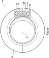
- FIG. 10 a cross-sectional view of the connector housing 114, taken along line 10-10 of FIG. 9 , is representatively illustrated. In this view, the manner in which the connectors 92 are positioned in the chamber 128 in the prong 120 can be more clearly seen.
- FIG. 11 a perspective view of the manner in which the upper and lower connector assemblies 64, 90 are operatively engaged downhole is representatively illustrated. Note that the prong 120 is axially received in the slot 122 as the upper and lower connector assemblies 64, 90 are engaged with each other.
- the alignment profiles 94, 96 maintain the rotational alignment between the upper and lower connector assemblies 64, 90.
- the axial biasing force exerted by the tubing contraction joint 70 maintains axial contact between the alignment profiles 94, 96.
- the engagement device 124 engages the protective barrier 82 to thereby expose the connectors 80 in the connector housing 66 when the prong 120 is received in the slot 122.
- a similar engagement device of the upper connector assembly 64 engages the protective barrier 126 of the lower connector assembly 90 when the upper and lower connector assemblies are engaged.
- FIGS. 12 & 13 cross-sectional views of the upper and lower connector assemblies 64, 90 are representatively illustrated.
- the upper and lower connector assemblies 64, 90 are rotationally aligned in these views, but are not yet operatively connected.
- the prong 120 is received in the slot 122.
- the protective barriers 82, 126 continue to shield the respective connectors 80, 92 from the well environment.
- FIG. 14 an enlarged view of the protective barrier 82 and the engagement device 124 is representatively illustrated.
- the engagement device 124 comprises an inwardly extending projection 130 having a lateral shoulder 130a formed thereon.
- the barrier 82 has a recess 132 formed therein.
- the recess 132 is complementarily shaped relative to the projection 130.
- the barrier 82 and the engagement device 124 will displace axially together.
- Shoulders (such as the shoulder 130a) on the projection 130 and in the recess 132 can engage each other to thereby prevent relative axial displacement between the engagement device 124 and the barrier 82.
- the engagement device 124 is part of the lower connector assembly 90 and the barrier 82 is part of the upper connector assembly 64, this means that the barrier 82 will displace axially with the lower connector assembly 90 relative to the upper connector assembly 64 when the connector assemblies are engaged.
- An engagement device 138 (see FIG. 13 ) of the upper connector assembly 64 includes an outwardly extending projection 140 having a lateral shoulder 140a formed thereon.
- the barrier 126 has a recess 142 formed therein.
- the recess 142 is complementarily shaped relative to the projection 140.
- the barrier 126 and the engagement device 138 will displace axially together.
- Shoulders (such as the shoulder 140a) on the projection 140 and in the recess 142 can engage each other to thereby prevent relative axial displacement between the engagement device 138 and the barrier 126.
- the engagement device 138 is part of the upper connector assembly 64 and the barrier 126 is part of the lower connector assembly 90, this means that the barrier 126 will displace axially with the upper connector assembly 64 relative to the lower connector assembly 90 when the connector assemblies are engaged.
- FIGS. 15 & 16 cross-sectional views of the upper and lower connector assemblies 64, 90 are representatively illustrated.
- the connector assemblies 64, 90 are operatively engaged in the configuration depicted in FIGS. 15 & 16 .
- the connectors 80, 92 are operatively connected, so that signals (such as communication or power signals) can be transmitted between the connectors.
- signals such as communication or power signals
- the barriers 82, 126 are displaced along respective slots or tracks 134, 136 formed in the upper and lower connector housings 66, 114.
- the barriers 82, 126 slide in the respective tracks 134, 136 after they have been engaged by the respective engagement devices 124, 138 and there is relative displacement between the upper and lower connector assemblies 64, 90. Note that the barriers 82, 126 can displace in either axial direction in the tracks 134, 136 and, thus, the barriers can be re-closed (after having been opened downhole) when the upper and lower connector assemblies 64, 90 are disengaged from each other downhole (such as, when the upper completion string 32 is retrieved from the well).
- the barriers 82, 126 are displaced to their open positions, and the chambers 84, 128 are open so that the connectors 80, 92 are exposed to each other.
- the connectors 80, 92 are operatively engaged with each other after the barriers 82, 126 are displaced to their open positions, and before the alignment profiles 94, 96 are fully engaged.
- FIGS. 17 & 18 cross-sectional views of the upper and lower connector assemblies 64, 90 are representatively illustrated.
- the connector assemblies 64, 90 are fully engaged with each other in the configuration depicted in FIGS. 17 & 18 .
- a compressive force has been applied after the alignment profiles 94, 96 are fully engaged, for example, by slacking off weight of the upper completion string 32 at the surface (e.g., during setting of the production packer 42 if it is a mechanically set packer).
- the tubing contraction joint 70 maintains the compressive force in the connected upper and lower connector assemblies 64, 90 after the packer 42 is set, as described above.
- the springs 118 are additionally compressed in the lower connector assembly 90. This additional compression begins just after the connectors 80, 92 are operatively connected and ends when the connector assemblies 64, 90 are fully engaged with each other (e.g., when the alignment profiles 94, 96 fully contact each other). The compressive biasing force exerted by the springs 118 helps to maintain the operative engagement of the connectors 80, 92.
- the protective barriers 82, 126 are depicted in the drawings as being in single flexible sheet or flat form. However, in other examples, the barriers 82, 126 could each comprise multiple connected-together components, and the barriers could have shapes other than sheet or flat. Thus, the scope of this disclosure is not limited to any particular form, shape, configuration or arrangement of the barriers 82, 126.
- the tracks 134, 136 in the respective upper and lower connector assemblies 64, 90 are depicted in the drawings as being axially elongated slots or grooves formed in the upper and lower connector housings 66, 114.
- the tracks could comprise structures (such as rails, guides or shoulders) that engage cooperative recesses or structures on the barriers 82, 126.
- the scope of this disclosure is not limited to any particular configuration of the engagement between the barriers 82, 126 and the tracks 134, 136.
- the scope of this disclosure is not limited to any particular configuration of the engagement between the engagement devices 124, 138 and the respective barriers 82, 126.
- projections or other structures on the barriers 82, 126 could engage recesses or structures of the engagement devices 124, 138.
- the chambers 84, 128 may initially be filled with a clean, viscous substance (such as, silicone grease) when the lower completion string 20 is installed in the well, and then the upper completion string 32 is run into the well to connect with the lower completion string.
- a clean, viscous substance such as, silicone grease
- the substance can help to exclude debris from the chambers 84, 128 and minimize well fluid entry into the chambers.
- the chambers 84, 128 and the substance therein are then exposed to the downhole environment only just before the connectors 80, 92 are operatively connected.
- lines 40, 60 could instead, or in addition, comprise any type or combination of lines (such as, electrical, hydraulic and/or optical lines).
- the upper and lower connector assemblies 64, 90 are uniquely configured to provide for a convenient and reliable wet mate connection 62 between the lines 40, 60.
- connection 62 can comprise first and second connector assemblies 90, 64.
- the first connector assembly 90 includes at least one first connector 92 and a first protective barrier 126, the first protective barrier 126 being displaceable between closed and open positions.
- the second connector assembly 64 includes a first engagement device 138 that displaces the first protective barrier 126 from the closed position to the open position in response to engagement between the first and second connector assemblies 90, 64.
- the first connector assembly 90 may include a seal bore 34 that sealingly receives therein a seal mandrel 36 of the second connector assembly 64 when the first and second connector assemblies 90, 64 are engaged.
- the second connector assembly 64 may include at least one second connector 80 and a second protective barrier 82, the second protective barrier 82 being displaceable between closed and open positions.
- the first connector assembly 90 may include a second engagement device 124 that displaces the second protective barrier 82 from the closed position to the open position in response to the engagement between the first and second connector assemblies 90, 64.
- the second connector assembly 64 may include a tubing contraction joint 70 that permits longitudinal compression of the second connector assembly 64 between a packer 42 and a connector housing 66 of the second connector assembly 64.
- the first protective barrier 126 may be displaceable along a track 136 formed on the first connector assembly 90.
- the first protective barrier 126 may include a recess 142 configured for engagement with the first engagement device 138.
- the first connector 92 may comprise an optical connector.
- the method can comprise: installing a first connector assembly 90 in the well, the first connector assembly 90 comprising a first connector 92 and a first alignment profile 96; then installing a second connector assembly 64 in the well, the second connector assembly 64 comprising a second connector 80 and a second alignment profile 94; then axially engaging the first and second connector assemblies 90, 64, thereby opening first and second protective barriers 126, 82 for the respective first and second connectors 92, 80, and operatively connecting the first and second connectors 92, 80, and engaging the first and second alignment profiles 96, 94, thereby preventing rotational misalignment of the first and second connectors 92, 80.
- the operatively connecting step may be performed after the first and second protective barriers 126, 82 opening step.
- the first and second protective barriers 126, 82 opening step may include displacing the first protective barrier 126 with the second connector assembly 64, and displacing the second protective barrier 82 with the first connector assembly 90.
- the first and second protective barriers 126, 82 opening step may include sliding the first protective barrier 126 relative to a first track 136 formed on the first connector assembly 90, and sliding the second protective barrier 82 relative to a second track 134 formed on the second connector assembly 64.
- the method can include axially separating the first and second connector assemblies 90, 64, thereby closing the first and second protective barriers 126, 82 for the respective first and second connectors 92, 80.
- the operatively connecting step may permit optical communication between the first and second connectors 92, 80.
- the system 10 can include: a first completion string 20 comprising a first optical connector assembly 90, the first optical connector assembly 90 including at least one first optical connector 92, a first packer 26 and a seal bore 34; and a second completion string 32 comprising a second optical connector assembly 64, the second optical connector assembly 64 including at least one second optical connector 80, a second packer 42 and a seal mandrel 36 sealingly engaged in the seal bore 34.
- the first and second optical connectors 92, 80 are operatively engaged between the first and second packers 26, 42.
- the first optical connector assembly 90 may include a first protective barrier 126 displaceable between closed and open positions.
- the second optical connector assembly 64 may include a first engagement device 138 that displaces the first protective barrier 126 from the closed position to the open position in response to engagement between the first and second optical connector assemblies 90, 64.
- the second optical connector assembly 64 may include a second protective barrier 82 displaceable between closed and open positions.
- the first optical connector assembly 90 may include a second engagement device 124 that displaces the second protective barrier 82 from the closed position to the open position in response to the engagement between the first and second optical connector assemblies 90, 64.
- the first protective barrier 126 may be displaceable along a track 136 formed on the first optical connector assembly 90.
- the first protective barrier 126 may include a recess 142 configured for engagement with the first engagement device 138.
- the second optical connector assembly 64 may include a tubing contraction joint 70 that permits longitudinal compression of the second completion string 32 between the second packer 42 and the second optical connector assembly 64.
Landscapes
- Engineering & Computer Science (AREA)
- Life Sciences & Earth Sciences (AREA)
- Geology (AREA)
- Mining & Mineral Resources (AREA)
- Mechanical Engineering (AREA)
- Physics & Mathematics (AREA)
- Environmental & Geological Engineering (AREA)
- Fluid Mechanics (AREA)
- General Life Sciences & Earth Sciences (AREA)
- Geochemistry & Mineralogy (AREA)
- Mechanical Coupling Of Light Guides (AREA)
Applications Claiming Priority (3)
| Application Number | Priority Date | Filing Date | Title |
|---|---|---|---|
| US16/529,624 US11162306B2 (en) | 2019-08-01 | 2019-08-01 | Downhole fiber optic wet mate connections |
| EP20746828.1A EP4007838B1 (de) | 2019-08-01 | 2020-07-10 | Faseroptische nassmattenverbindungen in einem bohrloch |
| PCT/US2020/041630 WO2021021418A1 (en) | 2019-08-01 | 2020-07-10 | Downhole fiber optic wet mate connections |
Related Parent Applications (2)
| Application Number | Title | Priority Date | Filing Date |
|---|---|---|---|
| EP20746828.1A Division EP4007838B1 (de) | 2019-08-01 | 2020-07-10 | Faseroptische nassmattenverbindungen in einem bohrloch |
| EP20746828.1A Division-Into EP4007838B1 (de) | 2019-08-01 | 2020-07-10 | Faseroptische nassmattenverbindungen in einem bohrloch |
Publications (2)
| Publication Number | Publication Date |
|---|---|
| EP4234879A2 true EP4234879A2 (de) | 2023-08-30 |
| EP4234879A3 EP4234879A3 (de) | 2023-09-06 |
Family
ID=71833487
Family Applications (2)
| Application Number | Title | Priority Date | Filing Date |
|---|---|---|---|
| EP20746828.1A Active EP4007838B1 (de) | 2019-08-01 | 2020-07-10 | Faseroptische nassmattenverbindungen in einem bohrloch |
| EP23181186.0A Pending EP4234879A3 (de) | 2019-08-01 | 2020-07-10 | Faseroptische nassmattenverbindungen in einem bohrloch |
Family Applications Before (1)
| Application Number | Title | Priority Date | Filing Date |
|---|---|---|---|
| EP20746828.1A Active EP4007838B1 (de) | 2019-08-01 | 2020-07-10 | Faseroptische nassmattenverbindungen in einem bohrloch |
Country Status (4)
| Country | Link |
|---|---|
| US (1) | US11162306B2 (de) |
| EP (2) | EP4007838B1 (de) |
| CA (1) | CA3149088A1 (de) |
| WO (1) | WO2021021418A1 (de) |
Families Citing this family (2)
| Publication number | Priority date | Publication date | Assignee | Title |
|---|---|---|---|---|
| WO2021247726A1 (en) * | 2020-06-03 | 2021-12-09 | Schlumberger Technology Corporation | System and method for connecting multiple stage completions |
| GB2615704A (en) | 2020-11-18 | 2023-08-16 | Schlumberger Technology Bv | Fiber optic wetmate |
Family Cites Families (8)
| Publication number | Priority date | Publication date | Assignee | Title |
|---|---|---|---|---|
| US7228898B2 (en) * | 2003-10-07 | 2007-06-12 | Halliburton Energy Services, Inc. | Gravel pack completion with fluid loss control fiber optic wet connect |
| US7165892B2 (en) * | 2003-10-07 | 2007-01-23 | Halliburton Energy Services, Inc. | Downhole fiber optic wet connect and gravel pack completion |
| US7210856B2 (en) * | 2004-03-02 | 2007-05-01 | Welldynamics, Inc. | Distributed temperature sensing in deep water subsea tree completions |
| US7640977B2 (en) * | 2005-11-29 | 2010-01-05 | Schlumberger Technology Corporation | System and method for connecting multiple stage completions |
| US8752635B2 (en) * | 2006-07-28 | 2014-06-17 | Schlumberger Technology Corporation | Downhole wet mate connection |
| US7900698B2 (en) * | 2007-08-13 | 2011-03-08 | Baker Hughes Incorporated | Downhole wet-mate connector debris exclusion system |
| BR112015013674B1 (pt) * | 2013-01-10 | 2020-12-29 | Halliburton Energy Services, Inc. | método de proteger as extremidades livres das linhas de comunicação dos detritos durante a conexão do fundo de poço em um poço subterrâneo |
| US9759016B2 (en) * | 2013-01-10 | 2017-09-12 | Halliburton Energy Services, Inc. | Protection assembly for downhole wet connectors |
-
2019
- 2019-08-01 US US16/529,624 patent/US11162306B2/en active Active
-
2020
- 2020-07-10 EP EP20746828.1A patent/EP4007838B1/de active Active
- 2020-07-10 WO PCT/US2020/041630 patent/WO2021021418A1/en unknown
- 2020-07-10 CA CA3149088A patent/CA3149088A1/en active Pending
- 2020-07-10 EP EP23181186.0A patent/EP4234879A3/de active Pending
Also Published As
| Publication number | Publication date |
|---|---|
| US11162306B2 (en) | 2021-11-02 |
| WO2021021418A1 (en) | 2021-02-04 |
| EP4234879A3 (de) | 2023-09-06 |
| EP4007838A1 (de) | 2022-06-08 |
| CA3149088A1 (en) | 2021-02-04 |
| WO2021021418A4 (en) | 2021-04-08 |
| EP4007838B1 (de) | 2023-09-13 |
| US20210032940A1 (en) | 2021-02-04 |
Similar Documents
| Publication | Publication Date | Title |
|---|---|---|
| US10301888B2 (en) | Travel joint release devices and methods | |
| US9945189B2 (en) | Travel joint release devices and methods | |
| US8061430B2 (en) | Re-settable and anti-rotational contraction joint with control lines | |
| US20080311776A1 (en) | Well Completion Self Orienting Connector system | |
| US9759016B2 (en) | Protection assembly for downhole wet connectors | |
| US9404314B2 (en) | Reciprocating debris exclusion device for downhole connectors | |
| US8915304B2 (en) | Traversing a travel joint with a fluid line | |
| EP3068966B1 (de) | Komplettierungssysteme mit einer dehnungsfuge und einer feuchtverbindung | |
| US20130075087A1 (en) | Module For Use With Completion Equipment | |
| EP4234879A2 (de) | Faseroptische nassmattenverbindungen in einem bohrloch | |
| US7730957B2 (en) | Well tool with line and installation method | |
| WO2016003394A1 (en) | Downhole expandable control line connector | |
| NO20230961A1 (en) | Downhole connector orientation for wetmate connectors | |
| US9091134B2 (en) | Expendable mechanical release packer plug for heavy mud | |
| US20220034170A1 (en) | Coated Electrical Connector Bands & Pressure Compensation Assemblies for Downhole Electrical Disconnect Tools | |
| US11377924B2 (en) | Method and system for boosting sealing elements of downhole barriers | |
| GB2551462A (en) | Travel joint release devices and methods | |
| Bellarby | Completion Equipment |
Legal Events
| Date | Code | Title | Description |
|---|---|---|---|
| PUAI | Public reference made under article 153(3) epc to a published international application that has entered the european phase |
Free format text: ORIGINAL CODE: 0009012 |
|
| STAA | Information on the status of an ep patent application or granted ep patent |
Free format text: STATUS: THE APPLICATION HAS BEEN PUBLISHED |
|
| PUAL | Search report despatched |
Free format text: ORIGINAL CODE: 0009013 |
|
| AC | Divisional application: reference to earlier application |
Ref document number: 4007838 Country of ref document: EP Kind code of ref document: P |
|
| AK | Designated contracting states |
Kind code of ref document: A2 Designated state(s): AL AT BE BG CH CY CZ DE DK EE ES FI FR GB GR HR HU IE IS IT LI LT LU LV MC MK MT NL NO PL PT RO RS SE SI SK SM TR |
|
| AK | Designated contracting states |
Kind code of ref document: A3 Designated state(s): AL AT BE BG CH CY CZ DE DK EE ES FI FR GB GR HR HU IE IS IT LI LT LU LV MC MK MT NL NO PL PT RO RS SE SI SK SM TR |
|
| RIC1 | Information provided on ipc code assigned before grant |
Ipc: E21B 17/02 20060101AFI20230728BHEP |
|
| STAA | Information on the status of an ep patent application or granted ep patent |
Free format text: STATUS: REQUEST FOR EXAMINATION WAS MADE |
|
| 17P | Request for examination filed |
Effective date: 20240301 |
|
| RBV | Designated contracting states (corrected) |
Designated state(s): AL AT BE BG CH CY CZ DE DK EE ES FI FR GB GR HR HU IE IS IT LI LT LU LV MC MK MT NL NO PL PT RO RS SE SI SK SM TR |