EP3068966B1 - Komplettierungssysteme mit einer dehnungsfuge und einer feuchtverbindung - Google Patents
Komplettierungssysteme mit einer dehnungsfuge und einer feuchtverbindung Download PDFInfo
- Publication number
- EP3068966B1 EP3068966B1 EP14861855.6A EP14861855A EP3068966B1 EP 3068966 B1 EP3068966 B1 EP 3068966B1 EP 14861855 A EP14861855 A EP 14861855A EP 3068966 B1 EP3068966 B1 EP 3068966B1
- Authority
- EP
- European Patent Office
- Prior art keywords
- connection device
- production string
- landing
- casing
- expansion joint
- Prior art date
- Legal status (The legal status is an assumption and is not a legal conclusion. Google has not performed a legal analysis and makes no representation as to the accuracy of the status listed.)
- Active
Links
- 238000004519 manufacturing process Methods 0.000 claims description 41
- 238000000034 method Methods 0.000 claims description 11
- 239000012530 fluid Substances 0.000 claims description 6
- 239000000835 fiber Substances 0.000 claims description 3
- 239000004020 conductor Substances 0.000 claims description 2
- 238000007789 sealing Methods 0.000 claims 1
- 230000015572 biosynthetic process Effects 0.000 description 9
- 238000005755 formation reaction Methods 0.000 description 9
- 229930195733 hydrocarbon Natural products 0.000 description 8
- 150000002430 hydrocarbons Chemical class 0.000 description 7
- 230000008602 contraction Effects 0.000 description 3
- 230000001939 inductive effect Effects 0.000 description 2
- 238000002955 isolation Methods 0.000 description 2
- 230000013011 mating Effects 0.000 description 2
- 238000012986 modification Methods 0.000 description 2
- 230000004048 modification Effects 0.000 description 2
- 239000004215 Carbon black (E152) Substances 0.000 description 1
- 239000004568 cement Substances 0.000 description 1
- 230000006835 compression Effects 0.000 description 1
- 238000007906 compression Methods 0.000 description 1
- 238000010586 diagram Methods 0.000 description 1
- 238000005553 drilling Methods 0.000 description 1
- 125000001183 hydrocarbyl group Chemical group 0.000 description 1
- 230000002706 hydrostatic effect Effects 0.000 description 1
- 238000009434 installation Methods 0.000 description 1
- 239000004576 sand Substances 0.000 description 1
Images
Classifications
-
- E—FIXED CONSTRUCTIONS
- E21—EARTH OR ROCK DRILLING; MINING
- E21B—EARTH OR ROCK DRILLING; OBTAINING OIL, GAS, WATER, SOLUBLE OR MELTABLE MATERIALS OR A SLURRY OF MINERALS FROM WELLS
- E21B43/00—Methods or apparatus for obtaining oil, gas, water, soluble or meltable materials or a slurry of minerals from wells
- E21B43/12—Methods or apparatus for controlling the flow of the obtained fluid to or in wells
-
- E—FIXED CONSTRUCTIONS
- E21—EARTH OR ROCK DRILLING; MINING
- E21B—EARTH OR ROCK DRILLING; OBTAINING OIL, GAS, WATER, SOLUBLE OR MELTABLE MATERIALS OR A SLURRY OF MINERALS FROM WELLS
- E21B17/00—Drilling rods or pipes; Flexible drill strings; Kellies; Drill collars; Sucker rods; Cables; Casings; Tubings
- E21B17/02—Couplings; joints
- E21B17/04—Couplings; joints between rod or the like and bit or between rod and rod or the like
- E21B17/07—Telescoping joints for varying drill string lengths; Shock absorbers
-
- E—FIXED CONSTRUCTIONS
- E21—EARTH OR ROCK DRILLING; MINING
- E21B—EARTH OR ROCK DRILLING; OBTAINING OIL, GAS, WATER, SOLUBLE OR MELTABLE MATERIALS OR A SLURRY OF MINERALS FROM WELLS
- E21B23/00—Apparatus for displacing, setting, locking, releasing or removing tools, packers or the like in boreholes or wells
- E21B23/02—Apparatus for displacing, setting, locking, releasing or removing tools, packers or the like in boreholes or wells for locking the tools or the like in landing nipples or in recesses between adjacent sections of tubing
Definitions
- This disclosure relates generally to a completion system wherein a production string for the production of hydrocarbons may include an expansion joint for accommodating variations in the length of the production string and a wet connect.
- Wells or wellbores are drilled in subsurface formations for the production of hydrocarbons (oil and gas). Modern wells can extend to great well depths, sometimes more than 2,500 meters. Hydrocarbons are trapped in various traps in the subsurface formations at different depths. The areas of the formation that contain the hydrocarbons are referred to as reservoirs or hydrocarbon-bearing formations or production zones.
- the wellbore is lined with a casing and the annulus between the casing and the wellbore is filled with cement. Perforations are made through the casing and the formation to allow the hydrocarbons to flow from the production zones into the wellbore.
- a production string is placed inside the casing to lift the hydrocarbons from the wellbore to the surface.
- a production string typically includes a lower completion section that includes various devices, such as sand screens, valves, packers, etc. in front of each zone and an upper completion section that typically includes a long tubing made by connecting or joining pipe sections, each about 30 feet in length.
- a liner hanger is placed on top of the tubing to attach or hang the tubing inside the casing at a selected location below the surface level.
- the lower completion section is deployed in the wellbore.
- the upper completion section is then lowered into the wellbore and attached to the top of the lower completion section. Operators determine the length of the upper completion section needed to hang the liner hanger at the selected location in the casing and to connect the upper completion section to the lower completion section.
- the tubing length can exceed 1,500 meters (about 15,000 feet). Due to the weight of the tubing, play in the tubing joints and for the expansion of the tubing after installation, an expansion joint is provided in the tubing to accommodate for such the tubing length changes.
- US 2013/048307 A1 describes a technique for connection and disconnection of an upper completion with respect to a lower completion of an overall completion system.
- the upper completion and the lower completion comprise hydraulic line segments and electrical line segments which are coupled via at least one hydraulic wet connect and at least one inductive coupler, respectively.
- the upper completion comprises a contraction joint having a coiled portion of the electric line to facilitate engagement of inductive coupler portions of the respective upper and lower completion. The contraction joint serves to facilitate tubing space out.
- a production string includes a device that can accommodate relatively large tubing length variations during deployment and an expansion joint for accommodating variations in length after deployment.
- the invention is defined in claim 1 and relates to a production string for use in a wellbore having a casing with a casing landing.
- the invention is defined in claim 9 and relates to a method of completing a wellbore having a casing with a casing landing.
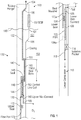
- FIG. 1 shows a production string wherein a lower section of the production string containing a lower portion of a wet connect has been deployed in the wellbore and an upper section of the production string is in the process of being deployed in the wellbore.
- FIG. 1 is a line diagram of a non-limiting embodiment of a production string or production assembly 100 for deployment in a wellbore 101 formed in a formation 102.
- the wellbore 101 is shown lined with a casing 104 that includes a landing 105 near the top of the casing 101.
- a blow-out-preventor 107 is deployed above the mud line 109 over the casing 101 to prevent blow-outs as is well known in the art.
- the production string 100 includes a lower string or completion section (also referred to herein as the "lower section") 110 and an upper completion string or upper completion section (also referred to herein as the "upper section”) 130.
- the lower section 110 may include devices known in the art to facilitate the production of hydrocarbons from the formation to the surface.
- the lower completion section 110 is isolated from the upper completion section 140 by an isolation packer 114.
- the lower completion section 110 includes a tubular 112 that has a polished bore receptacle ("PBR") 120 at the top of the tubular and a wet connect carrier 122 having a lower wet connect 125 on top of the PBR 120.
- a control line also referred to as the "communication line” or “communication link” 128 is run from the wet connect 125 to a circuit or control unit (not shown) in the lower completion section 110 for transmitting signals between the control circuit and the lower wet connect 125.
- the upper section 130 includes a tubular 132 that has a tubing hanger 134 at its upper end.
- the tubing hanger 134 has a landing 135 that lands on or hangs on to the landing 105 in the casing 104 when the upper section 130 is deployed in the casing 101.
- the upper section 130 contains an expansion joint (that may be a telescoping space out joint or TSOJ) 140 connected to the bottom end of the tubular 132.
- the expansion joint 140 includes a seal bore 142.
- the seal bore 142 is connected to a tubular 144 via a shear device 146, such as a shear pin.
- a seal 148 provides a seal between the seal bore 142 and the tubular 144.
- An upper wet connect carrier 160 having an upper wet connect 165 is connected to the lower end of the tubular 144.
- a control line 150 may be run from the surface along the tubular 132 and then along the seal bore 142 and then coiled around the tubular 144, as shown by coil 152.
- the communication line 150 terminates at the upper wet connect 165.
- the tubular 144 is then connected to a mandrel 170 that has an upper seal 172, a flow port 174 and a lower seal 176.
- the casing 101 and the production string 100 are filled with a fluid, such as drilling fluid, to provide a hydrostatic pressure in the casing greater that the formation pressure along the length of the wellbore to prevents the fluid from the formation 104 to enter into the production string 100.
- a fluid such as drilling fluid
- the tubular 132 is lowered to cause the lower seal 176 to engage with the PBR 120.
- pressure inside the upper section 130 increases, which produces a spike in the pressure measured at the surface. This enables an operator to know that the lower seal has engaged with the PBR 120.
- the flow port 174 allows fluid circulation to clean the area between the upper wet connect 165 and the lower wet connect 125.
- the upper section 130 is then lowered so that the upper wet connect 165 mates with the lower wet connect 125.
- Mating of the upper and lower wet connects 165 and 125 provides communication between the surface and the lower completion section 110. Mating of the upper and lower wet connects 165 and 125 prevents the upper section 130 to further move downward. The weight of the upper section 130 is not sufficient to break the shear device 146.
- the lower seal 176 is at a location 176a and the upper seal 172 has engaged with the PBR as shown by location 172a.
- the landing 135 of the tubing hanger 134 is still above the landing 105 of the casing 101.
- the distance "D1" between the lower wet connect 125 and the upper wet connect 165 is selected so that when the wet connects 125 and 165 mate, the landing 135 will remain above the landing 105 by a known distance.
- the tubular 132 is then pushed downward to break the shear device 142, which enables the seal bore 142 of the TSOJ 140 to move along the tubular 144 via the seal 146, which compresses the coil 152.
- the distance "D2" is greater than the distance needed to place the landing 135 onto the landing 105 after breaking the shear device 144.
- the communication link containing the links 128 and 150 may include one or more hydraulic lines, electrical lines (conductors), fiber optic lines and/or any other type of communication links known in the art.
- Various types of wet connects are known in the art and any suitable wet connect and communication link may be utilized for the purposes of this disclosure.
- the disclosure provides a completion system wherein a production string includes a lower completion section and an upper completion section.
- a lower wet connect carrier is placed at the top of a PBR above the lower completion section.
- a first control line is run from the lower wet connect carrier through an isolation packer to the lower completion section.
- the upper completion section includes an extended mandrel with two sets of seals (an upper seal set and a lower seal set) below an upper wet connect carrier, with a flow port placed below the upper seal set.
- the upper string is then lowered so that the upper seal set engages with the PBR and the upper wet connect fully mates (engages) with the lower wet connect.
- a TSOJ with a coiled control line is placed above the upper connect carrier with a higher shear force than is required to mate the upper wet connect with the lower wet connect.
- the TSOJ is sheared and moved downward to set the liner hanger in the casing. The coil and the TSOJ allow for tube movement throughout the life of the well.
- a long production string can require the use of a long expansion joint to allow for the make-up of a tubing hanger made by joining pipe sections and for additional 'play' in the string, such as due to the weight of the tubing.
- the production string 100 provides a first stroke (distance D1) via the mandrel to deploy the upper section 130 of the production string 100 (to connect the upper and lower wet connects) and a second stroke (distance D2) via the telescopic expansion joint 140 to set the liner hanger 134 in the casing 101.
- the production string 100 further provides coiled control lines (fiber optic, hydraulic, or electric) around the telescopic member 144 to allow for the compression of the control line during deployment of the production string 100 and for contraction and expansion of the production string 100 thereafter.
- the first stroke may be substantially greater than the second stroke.
- the first stroke may be about 100 feet and the second stroke may be about 40, the combination thereby providing sufficient safety margin for correctly landing the liner hanger and also providing for the expansion of the production string over the life of the well.
Landscapes
- Engineering & Computer Science (AREA)
- Life Sciences & Earth Sciences (AREA)
- Geology (AREA)
- Mining & Mineral Resources (AREA)
- Physics & Mathematics (AREA)
- Environmental & Geological Engineering (AREA)
- Fluid Mechanics (AREA)
- General Life Sciences & Earth Sciences (AREA)
- Geochemistry & Mineralogy (AREA)
- Mechanical Engineering (AREA)
- Earth Drilling (AREA)
Claims (12)
- Förderstrang (100) zur Verwendung in einem Bohrloch (101), das ein Casing (104) mit einem Casingabsatz (105) aufweist, wobei der Förderstrang (100) umfasst:einen unteren Abschnitt (110), der ein erstes Rohr (112) aufweist, das ein Polished Bore Receptacle (120) und eine erste Verbindungsvorrichtung (122) oben auf dem Polished Bore Receptacle (120) aufweist; undeinen oberen Abschnitt (130), der aufweist:ein zweites Rohr (132), das an seinem oberen Ende einen Rohraufhänger (134) hat, wobei der Rohraufhänger (134) einen Absatz (135) hat;ein Dehnungsstück (140), das mit dem unteren Ende des zweiten Rohrs (132) verbunden ist, wobei das Dehnungsstück (140) eine Teleskopvorrichtung aufweist, die ein erstes Element (142) hat, das mit einem zweiten Element (144) über eine Schervorrichtung (146) verbunden ist;eine zweite Verbindungsvorrichtung (160), die mit dem unteren Ende des zweiten Elements (144) des Dehnungsstücks (140) verbunden ist und dazu ausgelegt ist, in die erste Verbindungsvorrichtung (122) einzugreifen;einen Dorn (170), der mit dem zweiten Element (144) des Dehnungsstücks (140) verbunden ist; undwobei der Förderstrang (100) gekennzeichnet ist durch:eine untere Dichtung (176) auf dem Dorn (170) unter der zweiten Verbindungsvorrichtung (160), wobei der Eingriff der unteren Dichtung (176) mit dem Polished Bore Receptacle (120) eine Druckspitze erzeugt, die an einer Oberflächenstelle messbar ist, um den Eingriff zu bestätigen, wobei die erste Verbindungsvorrichtung (122) mit der zweiten Verbindungsvorrichtung (160) in Eingriff bringbar ist, und der Absatz (135) des Rohraufhängers (134) nach dem Eingreifen der ersten Verbindungsvorrichtung (122) und der zweiten Verbindungsvorrichtung (160) von dem Casingabsatz (105) beabstandet ist; unddas Dehnungsstück (140) einen Expansionsbereich (D2) hat, wobei ein Abschnitt des Expansionsbereichs (D2) nach dem Eingreifen der ersten Verbindungsvorrichtung (122) und der zweiten Verbindungsvorrichtung (160) einen Eingriff mit dem Casingabsatz (105) und dem Absatz (135) des Rohraufhängers (134) erlaubt.
- Förderstrang (100) nach Anspruch 1, wobei der Dorn (170) ferner wenigstens eine obere Dichtung (172) aufweist, die von der unteren Dichtung (176) beabstandet ist und dazu konfiguriert ist, mit dem Polished Bore Receptacle (120) in Dichtungseingriff zu stehen.
- Förderstrang (100) nach Anspruch 2, wobei die untere Dichtung (176) unter der ersten Verbindungsvorrichtung (122) positioniert ist, wenn die erste und die zweite Verbindungsvorrichtung miteinander in Eingriff stehen.
- Förderstrang (100) nach Anspruch 1 oder 2, wobei die erste Verbindungsvorrichtung (122) einen ersten Teil einer Nassverbindung (125) umfasst und die zweite Verbindungsvorrichtung (160) einen zweiten Teil der Nassverbindung (165) umfasst.
- Förderstrang (100) nach Anspruch 1, wobei das erste Element (142) abdichtend gegen das zweite Element (144) gleitet, wenn die Schervorrichtung (146) gelöst ist.
- Förderstrang (100) nach Anspruch 5, wobei der obere Abschnitt (130) ferner eine erste Kommunikationsverbindung (150) umfasst, die von einer Oberflächenstelle zur zweiten Verbindungsvorrichtung (160) verläuft und um das zweite Element (144) des Dehnungsstücks (140) gewickelt ist.
- Förderstrang (100) nach Anspruch 6, wobei der untere Abschnitt (110) eine zweite Kommunikationsverbindung (128) umfasst, die von der ersten Verbindungsvorrichtung (122) zu einer Position im unteren Abschnitt (110) verläuft.
- Förderstrang (100) nach Anspruch 7, wobei die erste Kommunikationsverbindung (150) und die zweite Kommunikationsverbindung (128) jeweils eine Verbindung beinhalten, die aus einer Gruppe ausgewählt ist, die aus einem elektrischen Leiter, einer Glasfaserverbindung und einer Fluidleitung besteht.
- Verfahren zum Komplettieren eines Bohrlochs (101), das ein Casing (104) mit einem Casingabsatz (105) aufweist, durch Verwendung eines Förderstrangs (100) nach einem der Ansprüche 1 bis 8, wobei das Verfahren umfasst:Bereitstellen des unteren Abschnitts (110) des Förderstrangs (100);Platzieren des unteren Abschnitts (110) in dem Bohrloch (101);Bereitstellen des oberen Abschnitts (130) des Förderstrangs (100);wobei das Verfahren gekennzeichnet ist durch:Absenken des oberen Abschnitts (130), um die untere Dichtung (176) des Dorns (170) mit dem Polished Bore Receptacle (120) in Eingriff zu bringen, durch Beobachten einer Druckspitze, die durch das Eingreifen der unteren Dichtung (176) mit dem Polished Bore Receptacle (120) erzeugt wird, um das Eingreifen der unteren Dichtung (176) und des Polished Bore Receptacle (120) zu bestätigen;Verbinden der ersten Verbindungsvorrichtung (122) mit der zweiten Verbindungsvorrichtung (160), wobei der Absatz (135) des Rohraufhängers (134) nach dem Verbinden der ersten Verbindungsvorrichtung (122) und der zweiten Verbindungsvorrichtung (160) vom Casingabsatz (105) beabstandet ist; undAbsenken des oberen Abschnitts (130) nach dem Verbinden der ersten Verbindungsvorrichtung (122) mit der zweiten Verbindungsvorrichtung (160) innerhalb eines Abschnitts des Dehnungsbereichs (D2), um den oberen Abschnitt (130) in dem Bohrloch (101) einzustellen, wobei der Casingabsatz (105) und der Absatz (135) des Rohraufhängers (134) in Eingriff stehen.
- Verfahren nach Anspruch 9, wobei das Verbinden der ersten Verbindungsvorrichtung (122) und der zweiten Verbindungsvorrichtung (160) ferner das Verbinden von zwei Nassverbindungen (125, 165) umfasst.
- Verfahren nach Anspruch 9 oder 10, ferner umfassend:Ausführen einer ersten Kommunikationsverbindung (128) von der ersten Verbindungsvorrichtung (122) zu einer Stelle im unteren Abschnitt (110); undAusführen einer zweiten Kommunikationsverbindung (150) von der zweiten Verbindungsvorrichtung (160) zu einer Stelle oberhalb des Dehnungsstücks (140).
- Verfahren nach einem der Ansprüche 9 bis 11, ferner umfassend das Bereitstellen einer Fluidverbindung über eine Öffnung (174) in dem Dorn (170) zwischen der ersten Verbindungsvorrichtung (122) und der zweiten Verbindungsvorrichtung (160), wenn sich der Dorn (170) in einer Dichtungsanordnung mit dem ersten Rohr (112, 120) befindet.
Applications Claiming Priority (2)
| Application Number | Priority Date | Filing Date | Title |
|---|---|---|---|
| US14/079,019 US10000995B2 (en) | 2013-11-13 | 2013-11-13 | Completion systems including an expansion joint and a wet connect |
| PCT/US2014/065361 WO2015073616A1 (en) | 2013-11-13 | 2014-11-13 | Completion systems including an expansion joint and a wet connect |
Publications (3)
| Publication Number | Publication Date |
|---|---|
| EP3068966A1 EP3068966A1 (de) | 2016-09-21 |
| EP3068966A4 EP3068966A4 (de) | 2017-07-26 |
| EP3068966B1 true EP3068966B1 (de) | 2020-02-12 |
Family
ID=53042714
Family Applications (1)
| Application Number | Title | Priority Date | Filing Date |
|---|---|---|---|
| EP14861855.6A Active EP3068966B1 (de) | 2013-11-13 | 2014-11-13 | Komplettierungssysteme mit einer dehnungsfuge und einer feuchtverbindung |
Country Status (6)
| Country | Link |
|---|---|
| US (1) | US10000995B2 (de) |
| EP (1) | EP3068966B1 (de) |
| AU (1) | AU2014348629B2 (de) |
| BR (1) | BR112016010556B1 (de) |
| DK (1) | DK3068966T3 (de) |
| WO (1) | WO2015073616A1 (de) |
Families Citing this family (9)
| Publication number | Priority date | Publication date | Assignee | Title |
|---|---|---|---|---|
| WO2015005897A1 (en) | 2013-07-08 | 2015-01-15 | Halliburton Energy Services, Inc. | Continuously sealing telescoping joint having multiple control lines |
| US9371703B2 (en) * | 2013-07-08 | 2016-06-21 | Halliburton Energy Services, Inc. | Telescoping joint with control line management assembly |
| US10267097B2 (en) | 2016-11-09 | 2019-04-23 | Baker Hughes, A Ge Company, Llc | Pressure compensating connector system, downhole assembly, and method |
| CA2967606C (en) | 2017-05-18 | 2023-05-09 | Peter Neufeld | Seal housing and related apparatuses and methods of use |
| US11258221B2 (en) | 2019-07-12 | 2022-02-22 | Oliden Technology, Llc | Rotatable and wet-mateable connector |
| US11441363B2 (en) * | 2019-11-07 | 2022-09-13 | Baker Hughes Oilfield Operations Llc | ESP tubing wet connect tool |
| US11111750B1 (en) | 2020-02-21 | 2021-09-07 | Saudi Arabian Oil Company | Telescoping electrical connector joint |
| GB2615704A (en) | 2020-11-18 | 2023-08-16 | Schlumberger Technology Bv | Fiber optic wetmate |
| WO2024015583A1 (en) * | 2022-07-14 | 2024-01-18 | Schlumberger Technology Corporation | Wetmate connection system and method |
Family Cites Families (12)
| Publication number | Priority date | Publication date | Assignee | Title |
|---|---|---|---|---|
| US6367552B1 (en) * | 1999-11-30 | 2002-04-09 | Halliburton Energy Services, Inc. | Hydraulically metered travel joint |
| US7222676B2 (en) * | 2000-12-07 | 2007-05-29 | Schlumberger Technology Corporation | Well communication system |
| AU2003904183A0 (en) | 2003-08-08 | 2003-08-21 | Woodside Energy Limited | Method for completion or work-over of a sub-sea well using a horizontal christmas tree |
| US7165892B2 (en) | 2003-10-07 | 2007-01-23 | Halliburton Energy Services, Inc. | Downhole fiber optic wet connect and gravel pack completion |
| US7503395B2 (en) * | 2005-05-21 | 2009-03-17 | Schlumberger Technology Corporation | Downhole connection system |
| US7509000B2 (en) | 2006-03-20 | 2009-03-24 | Baker Hughes Incorporated | Downhole optic fiber wet connect system and method |
| GB0607551D0 (en) | 2006-04-18 | 2006-05-24 | Read Well Services Ltd | Apparatus and method |
| US8752635B2 (en) * | 2006-07-28 | 2014-06-17 | Schlumberger Technology Corporation | Downhole wet mate connection |
| US7607477B2 (en) | 2006-09-06 | 2009-10-27 | Baker Hughes Incorporated | Optical wet connect |
| WO2011138574A2 (en) * | 2010-05-04 | 2011-11-10 | Bp Exploration Operating Company Limited | Control line protection |
| US20130048307A1 (en) | 2011-08-23 | 2013-02-28 | Schlumberger Technology Corporation | Completion for downhole applications |
| EP2959097B1 (de) * | 2013-02-21 | 2018-04-18 | Halliburton Energy Services, Inc. | Verfahren und vorrichtung zur orientierung von steuerleitungen entlang eines schiebegelenks |
-
2013
- 2013-11-13 US US14/079,019 patent/US10000995B2/en active Active
-
2014
- 2014-11-13 DK DK14861855.6T patent/DK3068966T3/da active
- 2014-11-13 EP EP14861855.6A patent/EP3068966B1/de active Active
- 2014-11-13 WO PCT/US2014/065361 patent/WO2015073616A1/en active Application Filing
- 2014-11-13 AU AU2014348629A patent/AU2014348629B2/en active Active
- 2014-11-13 BR BR112016010556-7A patent/BR112016010556B1/pt active IP Right Grant
Non-Patent Citations (1)
| Title |
|---|
| None * |
Also Published As
| Publication number | Publication date |
|---|---|
| BR112016010556A2 (de) | 2017-08-08 |
| US10000995B2 (en) | 2018-06-19 |
| BR112016010556B1 (pt) | 2021-11-03 |
| AU2014348629A1 (en) | 2016-05-26 |
| AU2014348629B2 (en) | 2018-05-17 |
| US20150129240A1 (en) | 2015-05-14 |
| DK3068966T3 (da) | 2020-05-04 |
| WO2015073616A1 (en) | 2015-05-21 |
| EP3068966A4 (de) | 2017-07-26 |
| EP3068966A1 (de) | 2016-09-21 |
Similar Documents
| Publication | Publication Date | Title |
|---|---|---|
| EP3068966B1 (de) | Komplettierungssysteme mit einer dehnungsfuge und einer feuchtverbindung | |
| US8746337B2 (en) | Single trip multi-zone completion systems and methods | |
| US6766857B2 (en) | Thru-tubing sand control method and apparatus | |
| US8720553B2 (en) | Completion assembly and methods for use thereof | |
| US8893794B2 (en) | Integrated zonal contact and intelligent completion system | |
| US8851189B2 (en) | Single trip multi-zone completion systems and methods | |
| US8985215B2 (en) | Single trip multi-zone completion systems and methods | |
| US9945203B2 (en) | Single trip completion system and method | |
| US20130075087A1 (en) | Module For Use With Completion Equipment | |
| US8839850B2 (en) | Active integrated completion installation system and method | |
| CA2894487A1 (en) | Reciprocating debris exclusion device for downhole connectors | |
| WO2014109753A1 (en) | Protection assembly for downhole wet connectors | |
| EP2351906A2 (de) | Nachrüstbares Bohrlochflüssigkeitsinjektionssystem | |
| US20230066633A1 (en) | Multilateral intelligent well completion methodology and system | |
| EP2900907B1 (de) | Fertigstellungsanordnung und verfahren zur verwendung davon |
Legal Events
| Date | Code | Title | Description |
|---|---|---|---|
| PUAI | Public reference made under article 153(3) epc to a published international application that has entered the european phase |
Free format text: ORIGINAL CODE: 0009012 |
|
| 17P | Request for examination filed |
Effective date: 20160524 |
|
| AK | Designated contracting states |
Kind code of ref document: A1 Designated state(s): AL AT BE BG CH CY CZ DE DK EE ES FI FR GB GR HR HU IE IS IT LI LT LU LV MC MK MT NL NO PL PT RO RS SE SI SK SM TR |
|
| AX | Request for extension of the european patent |
Extension state: BA ME |
|
| DAX | Request for extension of the european patent (deleted) | ||
| REG | Reference to a national code |
Ref country code: DE Ref legal event code: R079 Ref document number: 602014061044 Country of ref document: DE Free format text: PREVIOUS MAIN CLASS: E21B0017000000 Ipc: E21B0017070000 |
|
| A4 | Supplementary search report drawn up and despatched |
Effective date: 20170628 |
|
| RIC1 | Information provided on ipc code assigned before grant |
Ipc: E21B 17/07 20060101AFI20170622BHEP Ipc: E21B 23/02 20060101ALI20170622BHEP Ipc: E21B 43/12 20060101ALI20170622BHEP |
|
| STAA | Information on the status of an ep patent application or granted ep patent |
Free format text: STATUS: EXAMINATION IS IN PROGRESS |
|
| 17Q | First examination report despatched |
Effective date: 20180816 |
|
| GRAP | Despatch of communication of intention to grant a patent |
Free format text: ORIGINAL CODE: EPIDOSNIGR1 |
|
| STAA | Information on the status of an ep patent application or granted ep patent |
Free format text: STATUS: GRANT OF PATENT IS INTENDED |
|
| INTG | Intention to grant announced |
Effective date: 20190923 |
|
| RAP1 | Party data changed (applicant data changed or rights of an application transferred) |
Owner name: BAKER HUGHES, A GE COMPANY, LLC |
|
| GRAS | Grant fee paid |
Free format text: ORIGINAL CODE: EPIDOSNIGR3 |
|
| GRAA | (expected) grant |
Free format text: ORIGINAL CODE: 0009210 |
|
| STAA | Information on the status of an ep patent application or granted ep patent |
Free format text: STATUS: THE PATENT HAS BEEN GRANTED |
|
| AK | Designated contracting states |
Kind code of ref document: B1 Designated state(s): AL AT BE BG CH CY CZ DE DK EE ES FI FR GB GR HR HU IE IS IT LI LT LU LV MC MK MT NL NO PL PT RO RS SE SI SK SM TR |
|
| REG | Reference to a national code |
Ref country code: GB Ref legal event code: FG4D |
|
| REG | Reference to a national code |
Ref country code: CH Ref legal event code: EP |
|
| REG | Reference to a national code |
Ref country code: AT Ref legal event code: REF Ref document number: 1232332 Country of ref document: AT Kind code of ref document: T Effective date: 20200215 |
|
| REG | Reference to a national code |
Ref country code: IE Ref legal event code: FG4D |
|
| REG | Reference to a national code |
Ref country code: DE Ref legal event code: R096 Ref document number: 602014061044 Country of ref document: DE |
|
| REG | Reference to a national code |
Ref country code: DK Ref legal event code: T3 Effective date: 20200427 |
|
| REG | Reference to a national code |
Ref country code: NO Ref legal event code: T2 Effective date: 20200212 |
|
| PG25 | Lapsed in a contracting state [announced via postgrant information from national office to epo] |
Ref country code: FI Free format text: LAPSE BECAUSE OF FAILURE TO SUBMIT A TRANSLATION OF THE DESCRIPTION OR TO PAY THE FEE WITHIN THE PRESCRIBED TIME-LIMIT Effective date: 20200212 Ref country code: RS Free format text: LAPSE BECAUSE OF FAILURE TO SUBMIT A TRANSLATION OF THE DESCRIPTION OR TO PAY THE FEE WITHIN THE PRESCRIBED TIME-LIMIT Effective date: 20200212 |
|
| REG | Reference to a national code |
Ref country code: LT Ref legal event code: MG4D |
|
| REG | Reference to a national code |
Ref country code: NL Ref legal event code: MP Effective date: 20200212 |
|
| PG25 | Lapsed in a contracting state [announced via postgrant information from national office to epo] |
Ref country code: IS Free format text: LAPSE BECAUSE OF FAILURE TO SUBMIT A TRANSLATION OF THE DESCRIPTION OR TO PAY THE FEE WITHIN THE PRESCRIBED TIME-LIMIT Effective date: 20200612 Ref country code: GR Free format text: LAPSE BECAUSE OF FAILURE TO SUBMIT A TRANSLATION OF THE DESCRIPTION OR TO PAY THE FEE WITHIN THE PRESCRIBED TIME-LIMIT Effective date: 20200513 Ref country code: BG Free format text: LAPSE BECAUSE OF FAILURE TO SUBMIT A TRANSLATION OF THE DESCRIPTION OR TO PAY THE FEE WITHIN THE PRESCRIBED TIME-LIMIT Effective date: 20200512 Ref country code: SE Free format text: LAPSE BECAUSE OF FAILURE TO SUBMIT A TRANSLATION OF THE DESCRIPTION OR TO PAY THE FEE WITHIN THE PRESCRIBED TIME-LIMIT Effective date: 20200212 Ref country code: LV Free format text: LAPSE BECAUSE OF FAILURE TO SUBMIT A TRANSLATION OF THE DESCRIPTION OR TO PAY THE FEE WITHIN THE PRESCRIBED TIME-LIMIT Effective date: 20200212 Ref country code: HR Free format text: LAPSE BECAUSE OF FAILURE TO SUBMIT A TRANSLATION OF THE DESCRIPTION OR TO PAY THE FEE WITHIN THE PRESCRIBED TIME-LIMIT Effective date: 20200212 |
|
| PG25 | Lapsed in a contracting state [announced via postgrant information from national office to epo] |
Ref country code: NL Free format text: LAPSE BECAUSE OF FAILURE TO SUBMIT A TRANSLATION OF THE DESCRIPTION OR TO PAY THE FEE WITHIN THE PRESCRIBED TIME-LIMIT Effective date: 20200212 |
|
| PG25 | Lapsed in a contracting state [announced via postgrant information from national office to epo] |
Ref country code: PT Free format text: LAPSE BECAUSE OF FAILURE TO SUBMIT A TRANSLATION OF THE DESCRIPTION OR TO PAY THE FEE WITHIN THE PRESCRIBED TIME-LIMIT Effective date: 20200705 Ref country code: LT Free format text: LAPSE BECAUSE OF FAILURE TO SUBMIT A TRANSLATION OF THE DESCRIPTION OR TO PAY THE FEE WITHIN THE PRESCRIBED TIME-LIMIT Effective date: 20200212 Ref country code: ES Free format text: LAPSE BECAUSE OF FAILURE TO SUBMIT A TRANSLATION OF THE DESCRIPTION OR TO PAY THE FEE WITHIN THE PRESCRIBED TIME-LIMIT Effective date: 20200212 Ref country code: SK Free format text: LAPSE BECAUSE OF FAILURE TO SUBMIT A TRANSLATION OF THE DESCRIPTION OR TO PAY THE FEE WITHIN THE PRESCRIBED TIME-LIMIT Effective date: 20200212 Ref country code: CZ Free format text: LAPSE BECAUSE OF FAILURE TO SUBMIT A TRANSLATION OF THE DESCRIPTION OR TO PAY THE FEE WITHIN THE PRESCRIBED TIME-LIMIT Effective date: 20200212 Ref country code: RO Free format text: LAPSE BECAUSE OF FAILURE TO SUBMIT A TRANSLATION OF THE DESCRIPTION OR TO PAY THE FEE WITHIN THE PRESCRIBED TIME-LIMIT Effective date: 20200212 Ref country code: EE Free format text: LAPSE BECAUSE OF FAILURE TO SUBMIT A TRANSLATION OF THE DESCRIPTION OR TO PAY THE FEE WITHIN THE PRESCRIBED TIME-LIMIT Effective date: 20200212 Ref country code: SM Free format text: LAPSE BECAUSE OF FAILURE TO SUBMIT A TRANSLATION OF THE DESCRIPTION OR TO PAY THE FEE WITHIN THE PRESCRIBED TIME-LIMIT Effective date: 20200212 |
|
| REG | Reference to a national code |
Ref country code: DE Ref legal event code: R097 Ref document number: 602014061044 Country of ref document: DE |
|
| REG | Reference to a national code |
Ref country code: AT Ref legal event code: MK05 Ref document number: 1232332 Country of ref document: AT Kind code of ref document: T Effective date: 20200212 |
|
| PLBE | No opposition filed within time limit |
Free format text: ORIGINAL CODE: 0009261 |
|
| STAA | Information on the status of an ep patent application or granted ep patent |
Free format text: STATUS: NO OPPOSITION FILED WITHIN TIME LIMIT |
|
| 26N | No opposition filed |
Effective date: 20201113 |
|
| PG25 | Lapsed in a contracting state [announced via postgrant information from national office to epo] |
Ref country code: IT Free format text: LAPSE BECAUSE OF FAILURE TO SUBMIT A TRANSLATION OF THE DESCRIPTION OR TO PAY THE FEE WITHIN THE PRESCRIBED TIME-LIMIT Effective date: 20200212 Ref country code: AT Free format text: LAPSE BECAUSE OF FAILURE TO SUBMIT A TRANSLATION OF THE DESCRIPTION OR TO PAY THE FEE WITHIN THE PRESCRIBED TIME-LIMIT Effective date: 20200212 |
|
| PG25 | Lapsed in a contracting state [announced via postgrant information from national office to epo] |
Ref country code: SI Free format text: LAPSE BECAUSE OF FAILURE TO SUBMIT A TRANSLATION OF THE DESCRIPTION OR TO PAY THE FEE WITHIN THE PRESCRIBED TIME-LIMIT Effective date: 20200212 Ref country code: PL Free format text: LAPSE BECAUSE OF FAILURE TO SUBMIT A TRANSLATION OF THE DESCRIPTION OR TO PAY THE FEE WITHIN THE PRESCRIBED TIME-LIMIT Effective date: 20200212 |
|
| REG | Reference to a national code |
Ref country code: DE Ref legal event code: R119 Ref document number: 602014061044 Country of ref document: DE |
|
| PG25 | Lapsed in a contracting state [announced via postgrant information from national office to epo] |
Ref country code: MC Free format text: LAPSE BECAUSE OF FAILURE TO SUBMIT A TRANSLATION OF THE DESCRIPTION OR TO PAY THE FEE WITHIN THE PRESCRIBED TIME-LIMIT Effective date: 20200212 |
|
| REG | Reference to a national code |
Ref country code: CH Ref legal event code: PL |
|
| PG25 | Lapsed in a contracting state [announced via postgrant information from national office to epo] |
Ref country code: LU Free format text: LAPSE BECAUSE OF NON-PAYMENT OF DUE FEES Effective date: 20201113 |
|
| REG | Reference to a national code |
Ref country code: BE Ref legal event code: MM Effective date: 20201130 |
|
| PG25 | Lapsed in a contracting state [announced via postgrant information from national office to epo] |
Ref country code: CH Free format text: LAPSE BECAUSE OF NON-PAYMENT OF DUE FEES Effective date: 20201130 Ref country code: LI Free format text: LAPSE BECAUSE OF NON-PAYMENT OF DUE FEES Effective date: 20201130 |
|
| PG25 | Lapsed in a contracting state [announced via postgrant information from national office to epo] |
Ref country code: IE Free format text: LAPSE BECAUSE OF NON-PAYMENT OF DUE FEES Effective date: 20201113 Ref country code: FR Free format text: LAPSE BECAUSE OF NON-PAYMENT OF DUE FEES Effective date: 20201130 |
|
| PG25 | Lapsed in a contracting state [announced via postgrant information from national office to epo] |
Ref country code: DE Free format text: LAPSE BECAUSE OF NON-PAYMENT OF DUE FEES Effective date: 20210601 |
|
| PG25 | Lapsed in a contracting state [announced via postgrant information from national office to epo] |
Ref country code: TR Free format text: LAPSE BECAUSE OF FAILURE TO SUBMIT A TRANSLATION OF THE DESCRIPTION OR TO PAY THE FEE WITHIN THE PRESCRIBED TIME-LIMIT Effective date: 20200212 Ref country code: MT Free format text: LAPSE BECAUSE OF FAILURE TO SUBMIT A TRANSLATION OF THE DESCRIPTION OR TO PAY THE FEE WITHIN THE PRESCRIBED TIME-LIMIT Effective date: 20200212 Ref country code: CY Free format text: LAPSE BECAUSE OF FAILURE TO SUBMIT A TRANSLATION OF THE DESCRIPTION OR TO PAY THE FEE WITHIN THE PRESCRIBED TIME-LIMIT Effective date: 20200212 |
|
| PG25 | Lapsed in a contracting state [announced via postgrant information from national office to epo] |
Ref country code: MK Free format text: LAPSE BECAUSE OF FAILURE TO SUBMIT A TRANSLATION OF THE DESCRIPTION OR TO PAY THE FEE WITHIN THE PRESCRIBED TIME-LIMIT Effective date: 20200212 Ref country code: AL Free format text: LAPSE BECAUSE OF FAILURE TO SUBMIT A TRANSLATION OF THE DESCRIPTION OR TO PAY THE FEE WITHIN THE PRESCRIBED TIME-LIMIT Effective date: 20200212 |
|
| PG25 | Lapsed in a contracting state [announced via postgrant information from national office to epo] |
Ref country code: BE Free format text: LAPSE BECAUSE OF NON-PAYMENT OF DUE FEES Effective date: 20201130 |
|
| P01 | Opt-out of the competence of the unified patent court (upc) registered |
Effective date: 20230526 |
|
| PGFP | Annual fee paid to national office [announced via postgrant information from national office to epo] |
Ref country code: GB Payment date: 20231019 Year of fee payment: 10 |
|
| PGFP | Annual fee paid to national office [announced via postgrant information from national office to epo] |
Ref country code: NO Payment date: 20231023 Year of fee payment: 10 Ref country code: DK Payment date: 20231019 Year of fee payment: 10 |