EP4234877B1 - Extension ladder - Google Patents
Extension ladder Download PDFInfo
- Publication number
- EP4234877B1 EP4234877B1 EP23178070.1A EP23178070A EP4234877B1 EP 4234877 B1 EP4234877 B1 EP 4234877B1 EP 23178070 A EP23178070 A EP 23178070A EP 4234877 B1 EP4234877 B1 EP 4234877B1
- Authority
- EP
- European Patent Office
- Prior art keywords
- fly
- section
- cable
- base
- rail
- Prior art date
- Legal status (The legal status is an assumption and is not a legal conclusion. Google has not performed a legal analysis and makes no representation as to the accuracy of the status listed.)
- Active
Links
Images









Classifications
-
- E—FIXED CONSTRUCTIONS
- E06—DOORS, WINDOWS, SHUTTERS, OR ROLLER BLINDS IN GENERAL; LADDERS
- E06C—LADDERS
- E06C1/00—Ladders in general
- E06C1/02—Ladders in general with rigid longitudinal member or members
- E06C1/04—Ladders for resting against objects, e.g. walls poles, trees
- E06C1/08—Ladders for resting against objects, e.g. walls poles, trees multi-part
- E06C1/12—Ladders for resting against objects, e.g. walls poles, trees multi-part extensible, e.g. telescopic
-
- E—FIXED CONSTRUCTIONS
- E06—DOORS, WINDOWS, SHUTTERS, OR ROLLER BLINDS IN GENERAL; LADDERS
- E06C—LADDERS
- E06C7/00—Component parts, supporting parts, or accessories
- E06C7/02—Extending means
-
- E—FIXED CONSTRUCTIONS
- E06—DOORS, WINDOWS, SHUTTERS, OR ROLLER BLINDS IN GENERAL; LADDERS
- E06C—LADDERS
- E06C7/00—Component parts, supporting parts, or accessories
- E06C7/02—Extending means
- E06C7/04—Hand-operated extending means carried by the ladder
-
- E—FIXED CONSTRUCTIONS
- E06—DOORS, WINDOWS, SHUTTERS, OR ROLLER BLINDS IN GENERAL; LADDERS
- E06C—LADDERS
- E06C7/00—Component parts, supporting parts, or accessories
- E06C7/06—Securing devices or hooks for parts of extensible ladders
Definitions
- the present invention is related to extension ladders where the movement of the fly section relative to the base section is assisted with a force applicator.
- references to the "present invention” or “invention” relate to exemplary embodiments and not necessarily to every embodiment encompassed by the appended claims.
- the present invention is related to extension ladders with the movement of the fly section relative to the base section is assisted with a force applicator attached to the base rails of the base section and the fly rails of the fly section.
- Extension ladders have a fly section that slides relative to a base section to extend the length of the extension ladder. Moving the fly section upwards requires the user to be able to lift the fly section. Similarly, when moving the fly section downwards requires the user to be able to control the fly section so the fly section does not come crashing down, possibly damaging the extension ladder. What is needed is to provide an assistance force that is part of the extension ladder itself which reduces the weight of the fly section to make it easier to lift the fly section, and separately, make it easier and safer to control the fly section when the fly section downwards relative to the base section.
- KR 2018 0101734 discloses a two-stage ladder.
- the two-stage ladder comprises: a first ladder portion provided with a plurality of first horizontal rods; a second ladder portion slidably coupled to the first ladder portion, and provided with a plurality of second horizontal rods; and a clamping portion provided in a connection part between the first ladder portion and the second ladder portion such that a gap between the second ladder portion and the first ladder portion is fixed when the second ladder portion slides to a bottom end from the first ladder portion.
- FIGS. 1 to 24 Embodiments of the invention are shown by figures 1 to 24 .
- Figures 25 to 65 are provided to assist in understanding the invention.
- the operation of the force applicator 26 to move the fly section 20 relative to the base section 12 assists with the operation of the rope 27 and center pulley 28 and vice versa, but the force applicator 26 does not need the presence of a rope 27 and pulley 28, and the rope 27 and pulley 28 does not need the presence of the force applicator 26 to operate.
- Figure 27 shows the torque rung 36 when the fly section 20 is fully extended.
- Several turns of cable 32 are wrapped around the torque drum 40 and the torque spring 34 is exerting some amount of torsion on the torque drum 40. This torsion produces tension in the cable 32 which partially offsets the weight of the fly section 20.
- cable 32 is pulled from the torque drum 40 which causes the torque spring 34 to be wound up tighter, as seen in figure 28 .
- some amount of the fly section 20 weight is offset by the cable 32 throughout the fly's range of motion.
- the force applicator 26 may include a winch 62 attached to the base section 12, and a cable 32 attached to the winch 62 and the fly section 20.
- the fly section 20 is raised by the action of the winch 62 reeling in the cable 32.
- the winch 62 may include a winch frame 64 attached to the base rail, and a cable spool 66 mounted in the winch frame 64.
- the cable spool 66 has a portion 68 around which the cable 32 can wrap.
- Flanges 70 of the spool have gear teeth 72 which function as driven gears.
- a driving pinion 74 with gear teeth 72 is mounted in the winch frame 64.
- the driving pinion 74 engages the driven gears of the cable spool 66 so that rotating the driving pinion 74 CW causes the cable spool 66 to rotate CCW.
- the cable 32 is reeled in on the cable spool 66 when the driving pinion 74 is rotated CCW.
- a driving hex 76 connected to the driving pinion 74 extends up from the winch 62, the driving hex 76 engages a hex socket 78 which is held in a chuck 80 of a power drill 82.
- Figures 29 and 30 show views of the ladder 10 with the fly section 20 retracted and with the fly section 20 extended.
- the winch 62 is attached to the base section 12.
- the base pulley 29 is attached to the upper end of the first base rail 14.
- a cable 32 extends from the winch 62, passes around the base pulley 29, and is anchored to the fly section 20 at the fly cable anchor.
- the fly section 20 is raised by the action of the winch 62 reeling in the cable 32.
- FIG 31 shows the components of the winch 62.
- the winch frame 64 is attached to the first base rail 14.
- the cable spool 66 is mounted in the winch frame 64.
- the cable spool 66 has a portion 68 around which cable 32 can wrap.
- the flanges 70 of the spool have gear teeth 72 (not shown) so that they function as driven gears.
- a driving pinion 74 with gear teeth 72 (not shown) is mounted in the winch frame 64.
- the driving pinion 74 engages the driven gears of the cable spool 66 so that rotating the driving pinion 74 CW causes the cable spool 66 to rotate CCW.
- Cable 32 is reeled in on the cable spool 66 when it is rotated CCW.
- a driving hex 76 connected to the driving pinion 74 extends up from the winch 62. This driving hex 76 is designed to engage a hex socket 78 which is held in the chuck 80 of a power drill 82
- Figure 32 shows a power drill 82 with a hex socket 78 in its chuck 80 engaged with the driving hex 76 of the winch 62.
- Running the power drill 82 in the CW direction would reel in the cable 32 and so cause the fly section 20 to be extended.
- Figures 33A and 33B are broken views showing the path of the cable 32 when the fly section 20 is in its retracted position.
- Figures 34A and 34B show the winch 62 when the fly section 20 is in its extended position. Notice that cable 32 has wrapped around the cable spool 66.
- the winch 62 and cable 32 be used to hold the fly section 20 in position when the ladder 10 is in use.
- Conventional ladder locks (not shown) would be used.
- the purpose of the winch 62 and cable 32 is to enable a user to raise a ladder fly section 20 more easily by using a power drill 82. It is intended that when the power drill 82 is shut off or removed from the winch 62, the fly section 20 will descend by its own weight until its ladder locks properly engage a base rung, or it is fully retracted.
- Other types of motors to power the winch can be used other than a power drill 82.
- a power drill 82 is very convenient since it is commonly available when a ladder is used.
- any type of motor or generator preferably portable, can be used to lift the fly section which has an interface to transfer the rotational force generated by the motor to the extension ladder to raise and/or lower the fly section 20.
- the interface can be the hex socket 78 attached to a driveshaft of a motor and in turn rotationally connected with the driving hex 76 of the ladder 10.
- the motor effectively turns the pinion which lifts or lowers the fly section through the rack.
- the motor may be removably attached to the ladder 10 to cause the fly section 22 be raised or lowered relative to the base section 12, and then completely separated from the ladder 10 when the motor is no longer needed so as not to and further weight to the ladder 10.
- the motor is separate and apart from the ladder 10 so it does not contribute any weight to the ladder 10 and in weight to the ladder 10 when it is moved. Only when the ladder 10 is in position with the motor the connected with the ladder to lift and/or lower the fly section 20 relative to the base section 12.
- the force applicator 26 may be a clock-work type power spring 124.
- a clock-work type power spring 124 produces torque on the shaft 150 which is connected to the drum 88.
- the power spring 124 is wound most tightly.
- the power spring 124 unwinds (relaxes) as the fly section 20 moves toward the extended position.
- the power spring 124 is sized to apply torque on the drum 88 and so tension in the cable 32 and so partially offset the weight of the fly section 20 throughout the range of motion of the fly section 20.
- Figures 35-38 show a simplified extension ladder 10 in the retracted and extended positions.
- the climbing side is seen in figures 35 and 36 and the non-climbing side is in figures 37 and 38 .
- the major components are the power spring unit 86 which is connected to the first base rail 14 by a bracket 84, a pulley on the first base rail 14, a cable anchor 58 on the first fly rail 22, a drum 88 on the power spring unit 86, and the cable 32.
- One end of the cable 32 is fixed to and wraps around the drum 88.
- the cable 32 extends from the drum 88 to the pulley and then to the cable anchor 58 on the first fly rail 22.
- Tension produced in the cable 32 by the power spring unit 86 tends to make the fly section 20 move from the retracted to the extended position.
- Figure 39 and figure 40 show how the cable 32 wraps around the drum 88.
- the fly section 20 is extended as in figure 39 , some amount of cable 32 is taken up by the drum 88.
- the fly section 20 is retracted as in figure 40 , nearly all of the cable 32 has been unwrapped from the drum 88.
- Figure 41 and figure 42 show an additional feature.
- the power spring unit 86 When the ladder 10 is in use, the power spring unit 86 is in the deployed position of figure 41 , where the power spring unit 86 extend essentially perpendicular from the rungs 18. However, for transporting or storing the ladder 10, the power spring unit 86 can be moved into the stowed position of figure 42 , where the power spring unit 86 is in line and parallel with the rungs 18. (The cable is not shown.) This stowing action is accomplished by the power spring unit 86 pivoting about the end of its bracket 84, as seen in figures 43A and 43B .
- the bracket 84 is able to pivot about a pivot pin 146 between a deployed position where the drum 88 and power spring unit 86 extend perpendicularly from the base section 12 and a stowed position where the drum 88 and power spring unit 86 are parallel with the base section 12 for transporting or stowing the extension ladder 10.
- Figures 44A and 44B show more details of the power spring unit 86 and drum 88.
- a clock-work type power spring 92 attached to the shaft 150produces torque on the shaft 150 which is connected to the drum 88.
- the power spring 92 When the fly section 20 is fully retracted, the power spring 92 is wound most tightly. The power spring 92 unwinds (relaxes) as the fly section 20 moves toward the extended position.
- the power spring 92 is sized to apply torque on the drum 88 and so tension in the cable 32 and so partially offset the weight of the fly section 20 throughout the range of motion of the fly section 20.
- the power spring 92 is disposed in and protected by a housing 148.
- One end of the power spring 92 is attached to the housing 148 and the other end of the power spring 92 is attached to the shaft 150.
- the housing 148 By being attached to the housing 148, it is a fixed point about which the power spring 92 tightens or loosens as the shaft 150 rotates the power spring 92.
- the force applicator 26 is a foot pedal 94 which raises the fly section 20 a distance of one rung spacing each time the pedal is pressed down fully.
- a ratchet stud 156 is attached to the ratchet base 98.
- the ratchet base 98 When the ratchet base 98 is in its lowest position and therefore the foot pedal 94 is in its uppermost at-rest position, the ratchet stud 156 is in contact with the ratchet 152 and so causes it to be in its retracted position. Pushing down on the foot pedal 94 a short distance causes the ratchet base 98 to move upward and away from contact with the ratchet stud 156. This initial movement allows the ratchet 152 to move to its extended position.
- the diameters of the dual diameter drum 162 can be chosen so that an applied gas spring force of 200 pounds on the moveable end of the cable 32 will produce a reaction force on the fly section 20 (through the axle 110) of 20 pounds. Consequently, 1 foot of motion at the moveable end of the cable 32 will cause the fly section 20 to move 10 feet. Thus, a short stroke from a gas spring can produce a long travel of the fly section 20.
- Gas springs are desirable because of their very low spring rate over the length of their stroke. A low spring rate results in a uniform counterbalance force over the full range of the fly section's motion. However, more conventional springs, such as coil springs, could be used if a varying counterbalance force can be tolerated.
- the present disclosure pertains to a method for using an extension ladder 10.
- the method comprises the steps of extending a fly section 20 of the extension ladder 10 relative to a base section 12 of the extension ladder 10. There is the step of leaning the fly section 20 against an object. There is the step of sliding the fly section 20 downwards relative to the base section 12 while a force applicator 26 attached to the fly section 20 and the base section 12 applies a counterbalancing force to the fly section 20 to effectively reduce a weight of the fly section 20.
- the object can be a wall or a pole.
- the present disclosure pertains to a method for manufacturing an extension ladder 10.
- the method comprises the steps of attaching a cable anchor 58 to a first fly rail 22 of a fly section 20 of the extension ladder 10.
- the step of attaching the spring assembly 30 may include the steps of mounting a torque spring 34 around a torque shaft 38, fixing a second end 48 of a torque spring 34 to a torque rung body 42, and fixing a first end 46 of the torque spring 34 to a torque shaft flange 44 which is connected to the torque shaft 38.
- the torque shaft 38 extends and is connected to a torque drum 40.
- the present disclosure pertains to a method for using an extension ladder 10.
- the method comprises the steps of extending a fly section 20 of the extension ladder 10 relative to a base section 12 of the extension ladder 10. There is the step of leaning the fly section 20 against an object 60. There is the step of sliding the fly section 20 downwards relative to the base section 12 while a force applicator 26 attached to the fly section 20 and the base section 12 applies a counterbalancing force from a motor engaged with the force applicator 26 to effectively reduce a weight of the fly section 20.
- Each base rail having an upper end with a cap, and a lower end with a foot
- each fly rail having an upper end with a cap and a lower end with a cap.
- Each foot may be rotably attached to the lower end of each base rail, and may include a tread on the bottom of the foot to better grab the ground and prevent the ladder from sliding when leaning against an object.
- the foot may also include a spur plate extending from the foot to dig into the ground to better fix the ladder in place.
Landscapes
- Engineering & Computer Science (AREA)
- Mechanical Engineering (AREA)
- Ladders (AREA)
Description
- This is a nonprovisional of
U.S. provisional patent applications serial numbers 63/174,224 filed April 13, 2021 63/055,249 filed July 22, 2020 - The present invention is related to extension ladders where the movement of the fly section relative to the base section is assisted with a force applicator.(As used herein, references to the "present invention" or "invention" relate to exemplary embodiments and not necessarily to every embodiment encompassed by the appended claims.) More specifically, the present invention is related to extension ladders with the movement of the fly section relative to the base section is assisted with a force applicator attached to the base rails of the base section and the fly rails of the fly section.
- This section is intended to introduce the reader to various aspects of the art that may be related to various aspects of the present invention. The following discussion is intended to provide information to facilitate a better understanding of the present invention. Accordingly, it should be understood that statements in the following discussion are to be read in this light, and not as admissions of prior art.
- Extension ladders have a fly section that slides relative to a base section to extend the length of the extension ladder. Moving the fly section upwards requires the user to be able to lift the fly section. Similarly, when moving the fly section downwards requires the user to be able to control the fly section so the fly section does not come crashing down, possibly damaging the extension ladder. What is needed is to provide an assistance force that is part of the extension ladder itself which reduces the weight of the fly section to make it easier to lift the fly section, and separately, make it easier and safer to control the fly section when the fly section downwards relative to the base section.
-
KR 2018 0101734 - The invention is defined by the appended independent claim. Some optional features are defined by the dependent claims.
- Embodiments of the invention are shown by
figures 1 to 24 .Figures 25 to 65 are provided to assist in understanding the invention. -
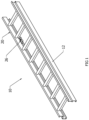
Figure 1 is a perspective view of the present invention with the fly section retracted over the base section of the extension ladder. -
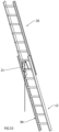
Figure 2 is a perspective view of the fly section extended from the base section. -
Figure 3 is a front view of the extension ladder of the present invention. -
Figure 4 is an overhead view of the extension ladder. -
Figure 5 is a close-up view of section A offigure 3 . -
Figure 6 is an underside perspective view of the fly section retracted over the base section. -
Figure 7 is an underside view of the fly section retracted and the base section hidden except for the spring assembly. -
Figure 8 is an underside view of the fly section extended from the base section. -
Figure 9 is an underside view of the fly section extended in the base section hidden except for the spring assembly. -
Figure 10 is an enlarged perspective view of the cable anchor is riveted to a fly rail with the base section hidden except for the spring assembly. -
Figure 11 is a perspective view of the extension ladder in the retracted position. -
Figure 12 is an enlarged view of section A offigure 11 . -
Figure 13 is a perspective view of a top portion of the base section. -
Figure 14 is a perspective view of a spring housing. -
Figure 15 is an exploded view of a spring assembly. -
Figure 16 is an underside view of the spring assembly. -
Figure 17 is a side view of the spring assembly. -
Figure 18 is an overhead view of the spring assembly. -
Figure 19 is a perspective view of the spring assembly. -
Figure 20 is an end view of the spring. -
Figure 21 shows the spring assembly and a retracted position. -
Figure 22 shows the spring assembly in the extended position. -
Figure 23 shows the extension ladder in the retracted position having a tork drum. -
Figure 24 shows the extension ladder in the extended position having a torque drum. -
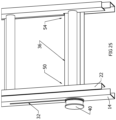
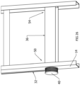
Figure 25 shows a bottom portion of the extension ladder with a torque drum in a retracted position. -
Figure 26 shows a bottom portion of the extension ladder with a torque drum in an extended position. -
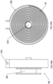
Figure 27 shows the underside of a torque rung with the fly section in an extended position. -
Figure 28 shows the underside of the torque rung with the fly section in a retracted position. -
Figure 29 is a perspective view of the extension ladder with a winch in a retracted position. -
Figure 30 is a perspective view of the extension ladder with a winch in an extended position. -
Figure 31 shows a winch attached to a first ladder rail. -
Figure 32 is a perspective view of the extension ladder in the retracted position having a winch with a power drill attached to the winch. -
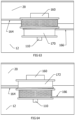
Figure 33A is a side view of a portion of the extension ladder with a winch in the retracted position. -
Figure 33B is an overhead view of the extension ladder with a winch in the retracted position. -
Figure 34A is a side view of a portion of the extension ladder with a winch in the extended position. -
Figure 34B is an overhead view of a portion of the extension ladder with a winch in the extended position. -
Figure 35 is a perspective view of the extension ladder with a power spring unit in an extended position. -
Figure 36 is a perspective view of the extension ladder in a retracted position having a power spring unit. -
Figure 37 is an underside perspective view of the extension ladder in an extended position having a power spring unit. -
Figure 38 is an underside perspective view of the extension ladder in a retracted position having a power spring unit. -
Figure 39 is an underside perspective view of the power spring unit attached to the extension ladder in an extended position. -
Figure 40 is an underside perspective view of the power spring unit attached to the extension ladder in a retracted position. -
Figure 41 is an overhead view of the extension ladder having a power spring unit in the deployed position. -
Figure 42 is an overhead view of the extension ladder having a power spring unit in the stowed position. -
Figure 43A shows the power spring unit in the stowed position. -
Figure 43B shows the power spring unit in the deployed position. -
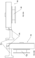
Figure 44A is a cutaway side view of the power spring unit. -
Figure 44B is a front view of the power spring unit. -
Figure 45 is a perspective view of the extension ladder in a retracted position having a foot pedal. -
Figure 46 is a side view of a portion of the ladder showing the tension spring, foot pedal up, ratchet stud and ratchet retracted. -
Figure 47 is an enlarged view of a portion of the extension ladder showing extended ratchet engaging the fly stud and the foot pedal moved a short distance downward relative tofigure 46 . -
Figure 48 is an enlarged view of a portion of the extension ladder showing the foot pedal fully down and the ratchet has moved the fly section up one incremental distance. -
Figure 49 is a perspective view of the extension ladder where the ratchet engages the fly stud. -
Figure 50 is a perspective view of the extension ladder where the fly section is in a partially extended position and the foot pedal is fully down. -
Figure 51 is a perspective view of the extension ladder in the extended position with the foot pedal fully down. -
Figure 52 is a perspective view of the extension ladder in the extended position with the ratchet retracted. -
Figure 53 is a perspective view of the underside of the extension ladder in the extended position having a foot pedal. -
Figure 54 is a perspective view of the extension ladder in a retracted position having a tension gas spring. -
Figure 55 is a perspective view of the extension ladder in an extended position having a tension gas spring. -
Figure 56 is an enlarged view of a portion of the extension ladder in a retracted position showing the tension gas spring, fixed pulley block and moving pulley block. -
Figure 57 is an enlarged view of a portion of the extension ladder in an extended position showing the tension gas spring, fixed pulley block and moving pulley block. -
Figure 58 is a perspective view of the extension ladder in a retracted position having a dual diameter drum. -
Figure 59 is an overhead view of the extension ladder in a retracted position having a dual diameter drum. -
Figure 60 is a side view of the extension ladder in a retracted position having a dual diameter drum. -
Figure 61 is a perspective view of the extension ladder in an extended position having a dual diameter drum. -
Figure 62 is a side view of the extension ladder in an extended position having a dual diameter drum. -
Figure 63 shows a dual diameter drum when the extension ladder is in a retracted position. -
Figure 64 shows a dual diameter drum and the extension ladder is in an extended position. -
Figure 65 shows the relationships between forces and motions of the extension ladder with a dual diameter drum. - Referring now to the drawings wherein like reference numerals refer to similar or identical parts throughout the several views, and more specifically to
figures 1 ,2 and11-13 thereof, there is shown anextension ladder 10. Theextension ladder 10 comprises abase section 12 having afirst base rail 14 and asecond base rail 16 in parallel and spaced relationship with thefirst base rail 14 andrungs 18 attached to and between the first and second base rails 14, 16. Theextension ladder 10 comprises afly section 20 having afirst fly rail 22 and asecond fly rail 24 in parallel and spaced relationship with thefirst fly rail 22 andrungs 18 attached to and between the first and second fly rails 22, 24. Thefly section 20 in sliding engagement with thebase section 12. Theextension ladder 10 comprises aforce applicator 26 attached to thebase section 12 and thefly section 20 which offsets some or all weight of thefly section 20. - The
force applicator 26 may offset at least 30% of the weight of thefly section 20. Theforce applicator 26 includes aspring assembly 30 attached to thefirst base rail 14 and acable 32 extending from thespring assembly 30 and attached to thefirst fly rail 22. As thefirst fly rail 22 slides relative to thefirst base rail 14, thecable 32 moves relative to thespring assembly 30 and thespring assembly 30 applies a spring force through thecable 32 to thefirst fly rail 22. The spring force may counterbalance the weight of thefly section 20 through thecable 32 when thefly section 20 is slid upwards relative to thebase section 12, making it easier for a user to slide thefly section 20 upwards relative to thebase section 12. - The spring force may counterbalance the weight of the
fly section 20 through thecable 32 when thefly section 20 is slid downwards, making it easier for the user to slide thefly section 20 downwards relative to thebase section 12. External guides 17 at the top of thebase section 12 may securely interlock the first and second base rails 14, 16 with the first and second fly rails 22, 24, respectively. There is acenter pulley 28 attached to one of therungs 18 of the base rail through which arope 27 extends, and arope clamp 25 attached to one of therungs 18 of the fly rail to attach therope 27 to thefly section 20 so when a free end of therope 27 that has passed through thecenter pulley 28, is pulled by the user, thefly section 20 slides upwards relative to thebase section 12, and when thefly section 20 is moved downwards relative to thebase section 12, the free end of therope 27 can be held by the user to slow down and control the descent of thefly section 20. Theforce applicator 26 further assists the movement of thefly section 20 relative to thebase section 12 by counterbalancing the weight of thefly section 20 so less force is necessary to pull on therope 27 to slide thefly section 20 upwards against the action of gravity relative to thebase section 12 compared to when theforce applicator 26 is not present. Similarly, theforce applicator 26 further assists the movement of thefly section 20 relative to thebase section 12 by counterbalancing the weight of thefly section 20 so less force is necessary to hold on to therope 27 and let therope 27 move through the hands of the user as thefly section 20 slides down under the action of gravity relative to thebase section 12 compared to when theforce applicator 26 is not present. Internal guides on the bottom of thefly section 20 securely interlock the first and second base rails 14, 16 with the first and second fly rails 22, 24, respectively.Locks 21 on thefly section 20 securely hold thefly section 20 to thebase section 12 at a desired position. In all the embodiments described herein of theforce applicator 26 with theladder 10, preferably there is present on the ladder 10 acenter pulley 28 and arope 27 to assist the user in moving thefly section 20, although thecenter pulley 28 and therope 27 are not necessary. Thecenter pulley 28 and therope 27 are completely separate and apart from theforce applicator 26. They do not interfere with each other. The operation of theforce applicator 26 to move thefly section 20 relative to thebase section 12 assists with the operation of therope 27 andcenter pulley 28 and vice versa, but theforce applicator 26 does not need the presence of arope 27 andpulley 28, and therope 27 andpulley 28 does not need the presence of theforce applicator 26 to operate. - The
spring assembly 30 includes anoutput spool 120 and astorage spool 122 disposed adjacent theoutput spool 120, and apower spring 124 positioned about theoutput spool 120 and thestorage spool 122 and extending therebetween. Seefigures 15-22 . As thecable 32 is extended from thespring assembly 30, theoutput spool 120 rotates causing thepower spring 124 on thestorage spool 122 to be pulled over to theoutput spool 120 and wrap around theoutput spool 120, with thepower spring 124 on thestorage spool 122 producing a resistive force which serves to counterbalance the weight of thefly section 20 through thecable 32. As thecable 32 is retracted to thespring assembly 30, thepower spring 124 on theoutput spool 120 is caused to be pulled over to thestorage spool 122 with thepower spring 124 on thestorage spool 122 producing a retractive force which serves to counterbalance the weight of thefly section 20 through thecable 32 and retract thecable 32. - The
spring assembly 30 may include adrum portion 132 positioned below theoutput spool 120 and attached to theoutput spool 120 in between theoutput spool 120 and thefirst fly rail 22. Thecable 32 wraps about thedrum portion 132. As thecable 32 extends from thedrum portion 132 when thefirst fly rail 22 slides downwards relative to thefirst base rail 14, thecable 32 rotates thedrum portion 132 which in turn rotates theoutput spool 120 causing thepower spring 124 on thestorage spool 122 to move to theoutput spool 120 and apply the resistive force to thecable 32. As thecable 32 is retracted to thedrum portion 132 when thefirst fly rail 22 slides upwards, thepower spring 124 on thestorage spool 122 pulls back thepower spring 124 on theoutput spool 120, applying the retractive force and causing theoutput spool 120 and thus thedrum portion 132 to rotate and retract thecable 32 to thedrum portion 132. Thespring assembly 30 may include aroller 19 adjacent theoutput spool 120 over which thecable 32 extends from theoutput spool 120. Theroller 19 serves to assist the proper movement of thecable 32 to and from thedrum portion 132, and avoid thecable 32 from tangling and guiding thecable 32 to the proper position. Thedrum portion 132 and theoutput spool 120, and thestorage spool 122 may extend fromrods 134 that extend from afoundation 144 which attaches to thefirst base rail 14, preferably on the inside of the web 52 of thefirst base rail 14. Theroller 19 may extend from a corner of thefoundation 144 in parallel with therods 134 that extend from thefoundation 144. - The
spring assembly 30 may include ahousing 136, as shown infigure 14 , in which thedrum portion 132, theoutput spool 120, theroller 19 and thestorage spool 122 are disposed. Thehousing 136 having anopening 138 through which thecable 32 extends to thefirst fly rail 22. Thehousing 136 with thespring assembly 30 and thecable 32 may be attached to a web 52 of thefirst base rail 14, as shown infigures 11 ,12 and13 . Thecable 32 extending from thehousing 136 to thefirst fly rail 22 along theweb 126 of thefirst fly rail 22. Theextension ladder 10 may include acable anchor 58 attached to thefirst fly rail 22, as shown infigures 7 ,9 and10 . Theforce applicator 26 may also include ahousing 136 with aspring assembly 30 and acable 32 and acable anchor 58 attached to thesecond base rail 16 andsecond fly rail 24 in the same way as described above with respect to thefirst base rail 14 and thefirst fly rail 22. Preferably thecable anchor 58 is attached adjacent the bottom of the first fly rail 22on the inside of theweb 126 of thefirst fly rail 22, and thehousing 136 with thespring assembly 30 attached adjacent the top of thefirst fly rail 22 on the inside of the web 52 of thefirst base rail 14. The inside of thefirst base rail 14 and the inside of thefirst fly rail 22 face each other, as shown infigure 5 . - The
force applicator 26 makes extending thefly section 20 easier as well as making retracting thefly section 20 much safer. With theforce applicator 26, a lower force is required to raise thefly section 20 relative to thebase section 12, as compared to the absence of aforce applicator 26. Theforce applicator 26 provides for a controlled/counter and balanced lowering of thefly section 20. Thefly section 20 can be safely lowered by releasing therope 27. The free end of the hoistrope 27 is contained and not contacting the ground. -
Figure 5 shows how thecable 32, after leaving theCTC spring assembly 30, is routed in the space between thefirst base rail 14 andfirst fly rail 22.Figures 7 and9 show the cable 32terminating at a cable anchor 58which is attached to the fly rail.Figure 10 shows that the cable anchor 58is riveted to theflange 128 of thefirst fly rail 22. The end of the cable 32passes through a hole in thecable anchor 58. A cable end 130is swaged onto the end of the cable 32to prevent the cable 32from pulling back through the hole in thecable anchor 58.Figure 6 shows thefly section 20 retracted with thebase section 12 whilefigure 7 shows thefly section 20 retracted but without thebase section 12.Figure 8 shows thefly section 20 extended with thebase section 12 whilefigure 9 shows thefly section 20 extended but without thebase section 12. -
Figure 23 and figure 24 show asimplified extension ladder 10 in the retracted and extended positions respectively with an alternative embodiment of theforce applicator 26 having atorque rung 36. Acable 32 is shown mounted on the left side of theladder 10. One end of thecable 32 is attached to atorque drum 40 of theforce applicator 26. Thecable 32 extends up to and passes around abase pulley 29 attached to the upper end of thebase section 12. From there thecable 32 extends down to acable anchor 58 near the lower end of thefirst fly rail 22.Figure 25 andfigure 26 show how thecable 32 wraps around thetorque drum 40. When thefly section 20 is retracted as infigure 25 , thecable 32 has been mostly unwound from thetorque drum 40. When thefly section 20 is extended as infigure 26 , some amount ofcable 32 has been wrapped around thetorque drum 40. Thecable 32 winds around thetorque drum 40 because of the action of atorque spring 34 contained within thetorque rung 36. It is the tension in thecable 32 which partially offsets the weight of thefly section 20. -
Figure 27 and figure 28 show the construction and the function of thetorque rung 36. Atorque spring 34 is mounted around atorque shaft 38. Thefirst end 46 of thetorque spring 34 is fixed to atorque shaft flange 44 which is connected to thetorque shaft 38 and rotates with thetorque shaft 38. Asecond end 48 of thetorque spring 34 is fixed to thetorque rung 36 body 42. Thetorque shaft 38 extends and is connected to the torque drum 40.As thetorque drum 40 rotates, thetorque shaft 38 rotates along with thetorque shaft flange 44 and thus thetorque spring 34, whosefirst end 46 is fixed to thetorque shaft flange 44, since thesecond end 48 of thetorque spring 34 is fixed to the torque rung body 42.Afirst end 50 of the torque rung body 42 is attached to a web 52 of thefirst base rail 14 and asecond end 54 of the torque rung body 42 is attached to a web 56 of thesecond base rail 16 with the web 52 of thefirst base rail 14 between thetorque shaft flange 44 and thetorque drum 40. Thetorque shaft 38 extending through the web 52 of thefirst base rail 14 from thetorque drum 40 to the web 52 of thefirst base rail 14. -
Figure 27 shows thetorque rung 36 when thefly section 20 is fully extended. Several turns ofcable 32 are wrapped around thetorque drum 40 and thetorque spring 34 is exerting some amount of torsion on thetorque drum 40. This torsion produces tension in thecable 32 which partially offsets the weight of thefly section 20. When thefly section 20 is moved to the retracted position,cable 32 is pulled from thetorque drum 40 which causes thetorque spring 34 to be wound up tighter, as seen infigure 28 . Thus, depending on the spring rate of thetorque spring 34 and its initial torsion when installed, some amount of thefly section 20 weight is offset by thecable 32 throughout the fly's range of motion. - With reference to
figures 29-34 , theforce applicator 26 may include awinch 62 attached to thebase section 12, and acable 32 attached to thewinch 62 and thefly section 20. Thefly section 20 is raised by the action of thewinch 62 reeling in thecable 32. Thewinch 62 may include awinch frame 64 attached to the base rail, and acable spool 66 mounted in thewinch frame 64. Thecable spool 66 has aportion 68 around which thecable 32 can wrap.Flanges 70 of the spool havegear teeth 72 which function as driven gears. A drivingpinion 74 withgear teeth 72 is mounted in thewinch frame 64. The drivingpinion 74 engages the driven gears of thecable spool 66 so that rotating the drivingpinion 74 CW causes thecable spool 66 to rotate CCW. Thecable 32 is reeled in on thecable spool 66 when the drivingpinion 74 is rotated CCW. A drivinghex 76 connected to the drivingpinion 74 extends up from thewinch 62, the drivinghex 76 engages ahex socket 78 which is held in achuck 80 of apower drill 82. -
Figures 29 and30 show views of theladder 10 with thefly section 20 retracted and with thefly section 20 extended. Thewinch 62 is attached to thebase section 12. Thebase pulley 29 is attached to the upper end of thefirst base rail 14. Acable 32 extends from thewinch 62, passes around thebase pulley 29, and is anchored to thefly section 20 at the fly cable anchor. Thefly section 20 is raised by the action of thewinch 62 reeling in thecable 32. -
Figure 31 shows the components of thewinch 62. Thewinch frame 64 is attached to thefirst base rail 14. Thecable spool 66 is mounted in thewinch frame 64. Thecable spool 66 has aportion 68 around whichcable 32 can wrap. Theflanges 70 of the spool have gear teeth 72 (not shown) so that they function as driven gears. A drivingpinion 74 with gear teeth 72 (not shown) is mounted in thewinch frame 64. The drivingpinion 74 engages the driven gears of thecable spool 66 so that rotating the drivingpinion 74 CW causes thecable spool 66 to rotate CCW.Cable 32 is reeled in on thecable spool 66 when it is rotated CCW. A drivinghex 76 connected to the drivingpinion 74 extends up from thewinch 62. This drivinghex 76 is designed to engage ahex socket 78 which is held in thechuck 80 of apower drill 82. -
Figure 32 shows apower drill 82 with ahex socket 78 in itschuck 80 engaged with the drivinghex 76 of thewinch 62. Running thepower drill 82 in the CW direction would reel in thecable 32 and so cause thefly section 20 to be extended. -
Figures 33A and 33B are broken views showing the path of thecable 32 when thefly section 20 is in its retracted position. -
Figures 34A and 34B show thewinch 62 when thefly section 20 is in its extended position. Notice thatcable 32 has wrapped around thecable spool 66. - Note, it is not intended that the
winch 62 andcable 32 be used to hold thefly section 20 in position when theladder 10 is in use. Conventional ladder locks (not shown) would be used. The purpose of thewinch 62 andcable 32 is to enable a user to raise aladder fly section 20 more easily by using apower drill 82. It is intended that when thepower drill 82 is shut off or removed from thewinch 62, thefly section 20 will descend by its own weight until its ladder locks properly engage a base rung, or it is fully retracted. Other types of motors to power the winch can be used other than apower drill 82. Apower drill 82 is very convenient since it is commonly available when a ladder is used. Basically, any type of motor or generator, preferably portable, can be used to lift the fly section which has an interface to transfer the rotational force generated by the motor to the extension ladder to raise and/or lower thefly section 20. The interface can be thehex socket 78 attached to a driveshaft of a motor and in turn rotationally connected with the drivinghex 76 of theladder 10. Alternatively, there may be no cable but instead a rack on one of the fly rails of thefly section 20, which engages with a pinion on thebase section 12, such as one of the base rails adjacent to one of the fly rails that has the rack. The motor effectively turns the pinion which lifts or lowers the fly section through the rack. The motor may be removably attached to theladder 10 to cause thefly section 22 be raised or lowered relative to thebase section 12, and then completely separated from theladder 10 when the motor is no longer needed so as not to and further weight to theladder 10. Ideally, the motor is separate and apart from theladder 10 so it does not contribute any weight to theladder 10 and in weight to theladder 10 when it is moved. Only when theladder 10 is in position with the motor the connected with the ladder to lift and/or lower thefly section 20 relative to thebase section 12. - In another embodiment, the
force applicator 26 may be a clock-worktype power spring 124. A clock-worktype power spring 124 produces torque on theshaft 150 which is connected to thedrum 88. When thefly section 20 is fully retracted, thepower spring 124 is wound most tightly. Thepower spring 124 unwinds (relaxes) as thefly section 20 moves toward the extended position. Thepower spring 124 is sized to apply torque on thedrum 88 and so tension in thecable 32 and so partially offset the weight of thefly section 20 throughout the range of motion of thefly section 20. -
Figures 35-38 show asimplified extension ladder 10 in the retracted and extended positions. The climbing side is seen infigures 35 and36 and the non-climbing side is infigures 37 and 38 . The major components are thepower spring unit 86 which is connected to thefirst base rail 14 by abracket 84, a pulley on thefirst base rail 14, acable anchor 58 on thefirst fly rail 22, adrum 88 on thepower spring unit 86, and thecable 32. One end of thecable 32 is fixed to and wraps around thedrum 88. Thecable 32 extends from thedrum 88 to the pulley and then to thecable anchor 58 on thefirst fly rail 22. Tension produced in thecable 32 by thepower spring unit 86 tends to make thefly section 20 move from the retracted to the extended position. -
Figure 39 and figure 40 show how thecable 32 wraps around thedrum 88. When thefly section 20 is extended as infigure 39 , some amount ofcable 32 is taken up by thedrum 88. When thefly section 20 is retracted as infigure 40 , nearly all of thecable 32 has been unwrapped from thedrum 88. -
Figure 41 and figure 42 show an additional feature. When theladder 10 is in use, thepower spring unit 86 is in the deployed position offigure 41 , where thepower spring unit 86 extend essentially perpendicular from therungs 18. However, for transporting or storing theladder 10, thepower spring unit 86 can be moved into the stowed position offigure 42 , where thepower spring unit 86 is in line and parallel with therungs 18. (The cable is not shown.) This stowing action is accomplished by thepower spring unit 86 pivoting about the end of itsbracket 84, as seen infigures 43A and 43B . Thebracket 84 is able to pivot about apivot pin 146 between a deployed position where thedrum 88 andpower spring unit 86 extend perpendicularly from thebase section 12 and a stowed position where thedrum 88 andpower spring unit 86 are parallel with thebase section 12 for transporting or stowing theextension ladder 10. -
Figures 44A and 44B show more details of thepower spring unit 86 anddrum 88. A clock-work type power spring 92attached to the shaft 150produces torque on theshaft 150 which is connected to thedrum 88. When thefly section 20 is fully retracted, thepower spring 92 is wound most tightly. Thepower spring 92 unwinds (relaxes) as thefly section 20 moves toward the extended position. Thepower spring 92 is sized to apply torque on thedrum 88 and so tension in thecable 32 and so partially offset the weight of thefly section 20 throughout the range of motion of thefly section 20. Thepower spring 92 is disposed in and protected by ahousing 148. One end of thepower spring 92 is attached to thehousing 148 and the other end of thepower spring 92 is attached to theshaft 150. By being attached to thehousing 148, it is a fixed point about which thepower spring 92 tightens or loosens as theshaft 150 rotates thepower spring 92. - In another embodiment, the
force applicator 26 is afoot pedal 94 which raises the fly section 20 a distance of one rung spacing each time the pedal is pressed down fully. -
Figure 45 shows theladder 10 with thefly section 20 retracted. Afoot pedal 94 slides up and down in afoot pedal track 96 attached to the lower end of a base rail. Acable 32 is attached to thefoot pedal 94. Thecable 32 extends up to abase pulley 29 at the upper end of the base rail. Thecable 32 passes around thebase pulley 29 and is attached to aratchet base 98. Thisratchet base 98 is constrained to slide up and down the base rail. Atension spring 100 biases theratchet base 98 to move down thefirst base rail 14, and so, also biases thefoot pedal 94 to move upward in thefoot pedal track 96 because of tension in thecable 32. The total travel of the ratchet or thefoot pedal 94 is about 14 inches. - A
ratchet 152 is attached to theratchet base 98. Aratchet spring 154 biases theratchet 152 toward its extended position, as seen infigures 46 and47 . - A
ratchet stud 156 is attached to theratchet base 98. When theratchet base 98 is in its lowest position and therefore thefoot pedal 94 is in its uppermost at-rest position, theratchet stud 156 is in contact with theratchet 152 and so causes it to be in its retracted position. Pushing down on the foot pedal 94 a short distance causes theratchet base 98 to move upward and away from contact with theratchet stud 156. This initial movement allows theratchet 152 to move to its extended position. - Fly
studs 158 are attached to thefirst fly rail 22 at incremental distances. These increments correspond to the distances between theladder rungs 18. These flystuds 158 are located so as to engage with theratchet 152 when theratchet 152 is extended, but will pass freely over theratchet 152 when it is retracted. - It is assumed that the
ladder 10 is equipped with conventional ladder locks 21 and a standard hoisting rope arrangement. For simplicity, the hoisting rope and its pulley are shown only infigures 52 and53 . -
Figure 46 shows a side view of theladder 10 shown infigure 45 . Thefoot pedal 94 is in its uppermost position. Contact with theratchet stud 156 is holding theratchet 152 in its retracted position. It should be noted that when theladder 10 is in this condition, the hoisting rope could be used to raise or lower thefly section 20 in a conventional manner. - In
figure 47 , the user has pushed downward on the foot pedal 94 a short distance. This initial motion has allowed theratchet 152 to extend so that it might engage a fly stud. - In
figure 48 , the user has pushed thefoot pedal 94 all the way down. Theratchet base 98 and ratchet 152 have moved upward a full incremental distance, carrying a fly stud (and the first fly rail 22) with it.Figures 47 and 48 are seen in perspective infigures 49 and50 . - After the
fly section 20 has risen one incremental distance, the ladder locks 21 would engage thefly section 20 as usual. At this point, the user can allow thefoot pedal 94 to rise to its uppermost position which lowers theratchet base 98 and ratchet 152 until they are in a position to engage the next fly stud. By repeating the up and down motion of thefoot pedal 94, thefly section 20 is easily raised, using leg strength, one rung at a time. -
Figure 51 shows theladder 10 which has just been fully extended, thefoot pedal 94 is still down. -
Figures 52 and53 show theladder 10 fully extended, thefoot pedal 94 in its uppermost at-rest position, theratchet 152 retracted. At this point thefly section 20 may be lowered using the hoisting rope in the conventional way. - Note that when the
foot pedal 94 is in its uppermost position, thefly section 20 may be lowered from any incremental position by using the hoisting rope. - In another embodiment, the
force applicator 26 includes atension gas spring 102, a fixedpulley block 104 and a movingpulley block 106.Figures 54 and 55 show views of theladder 10 with thefly section 20 retracted and with thefly section 20 extended. Thetension gas spring 102 is attached to the lower end of afirst base rail 14. Thebase pulley 29 is attached to the upper end of thefirst base rail 14. Theaxle 110 of the fixedpulley block 104 is attached to thefirst base rail 14. The movingpulley block 106 is attached to the end of the tension gasspring piston rod 112. Acable 32 has one end attached to the fixedpulley block 104. Thecable 32 passes back and forth between the fixed and movingpulley blocks outgoing cable 32 extends to thebase pulley 29, passes around it, and is attached to thefirst fly rail 22 at the fly cable attachment. -
Figures 56 and 57 show the operation of thecable 32, pulley blocks, andtension gas spring 102. When theladder fly section 20 is in the retracted position as shown infigure 56 , the tension gasspring piston rod 112 is fully extended, which puts the pulley blocks close to each other. In this conditionenough cable 32 has been extended from the pulley blocks to allow thefly section 20 to be in its retracted position. When theladder fly section 20 is in its extended position as shown infigure 57 , the pulley blocks have been moved apart by the retraction of the tension gasspring piston rod 112 andcable 32 has been drawn into the pulley blocks which results in thefly section 20 being in its extended position. - The action of the pulley blocks is that of a conventional block and tackle arrangement. The motion of the moving
pulley block 106 produces an amplified motion ofoutgoing cable 32 in proportion to the number of times thecable 32 passes back and forth between the pulley blocks. The tension in thecable 32 as it leaves the pulley blocks is reduced from the tension of the gas spring by that same ratio. - For example, if the
cable 32 passes back and forth 10 times between the pulley blocks, theoutgoing cable 32 tension will be 1/10 of the gas spring tension. But theoutgoing cable 32 will extend 10 times the motion of the gas spring. So, a 200-pound gas spring with an 8-inch stroke will be able to supply a tension of 20 pounds over 80 inches of cable extension. This 20-pound tension can serve to counteract some amount of thefly section 20 weight, enabling the user to extend and retract thefly section 20 easily. - It is assumed that the counterbalance force will always be less than the weight of the
fly section 20. Locking thefly section 20 at the desired height prior to climbing will be accomplished by conventional ladder locks 21 on thefly section 20 engaging the appropriate base rung. - In another embodiment, the
force applicator 26 includes adual diameter drum 162.Figures 58 ,59 and 60 show views of theladder 10 with thefly section 20 retracted. Atension gas spring 102 is fixed to the lower end of thefirst base rail 14. Adrum anchor 160 is attached to thefirst fly rail 22. Adual diameter drum 162 rotates on anaxle 110 which is part of thedrum anchor 160. There is acable anchor 58 attached to the upper end of thebase section 12. Thelower cable 164 extends from the moving end of the gas spring and wraps around and is attached to thelarger diameter portion 172 of thedual diameter drum 162. Theupper cable 166 is attached to thecable anchor 58 and wraps around and is fixed to thesmaller diameter portion 170 of thedual diameter drum 162. (Figures 63 and 64 show the drum diameters more clearly.)Figure 61 and62 show views of theladder 10 with thefly section 20 fully extended. -
Figure 63 and figure 64 show how the cables wrap around thedual diameter drum 162. When thefly section 20 is retracted as infigure 63 , most of thelower cable 164 is wrapped around thelarger diameter portion 172 of thedual diameter drum 162 and theupper cable 166 is mostly un-wrapped from the smaller diameter portion 170of thedual diameter drum 162. When thefly section 20 is extended as infigure 64 , most of thelower cable 164 has unwrapped from the larger diameter portion 172of thedual diameter drum 162 and most of theupper cable 166 has wrapped around the smaller diameter portion 170of thedual diameter drum 162. -
Figure 65 shows the principle of operation of thisdual diameter drum 162 design. The upper part offigure 65 shows thedrum 88 and cables when thefly section 20 is retracted. The gas spring applies a tension force to the moveable end of thelower cable 164. The reaction force on theaxle 110 of thedrum 88 is a fraction of the applied force on thelower cable 164. This fraction is in proportion to the ratio of the two diameters of thedual diameter drum 162. This reaction force on theaxle 110 acts on thefly section 20 to offset its weight. The lower part offigure 65 shows thedual diameter drum 162 and cables when thefly section 20 is extended. Thedual diameter drum 162 will roll toward the fixed end of the upper cable 166 (carrying the first fly rail 22with it) a distance which is a multiplication of the applied motion of the end of thecable 32. - For example, the diameters of the
dual diameter drum 162 can be chosen so that an applied gas spring force of 200 pounds on the moveable end of thecable 32 will produce a reaction force on the fly section 20 (through the axle 110) of 20 pounds. Consequently, 1 foot of motion at the moveable end of thecable 32 will cause thefly section 20 to move 10 feet. Thus, a short stroke from a gas spring can produce a long travel of thefly section 20. - One other virtue of this embodiment is the fact that gas springs typically have a very low spring rate. So, the force which offsets the weight of the
fly section 20 will remain nearly constant throughout the travel of thefly section 20. - This explanation and figures have shown a gas spring being used. Gas springs are desirable because of their very low spring rate over the length of their stroke. A low spring rate results in a uniform counterbalance force over the full range of the fly section's motion. However, more conventional springs, such as coil springs, could be used if a varying counterbalance force can be tolerated.
- The present disclosure pertains to a method for using an
extension ladder 10. The method comprises the steps of extending afly section 20 of theextension ladder 10 relative to abase section 12 of theextension ladder 10. There is the step of leaning thefly section 20 against an object. There is the step of sliding thefly section 20 downwards relative to thebase section 12 while aforce applicator 26 attached to thefly section 20 and thebase section 12 applies a counterbalancing force to thefly section 20 to effectively reduce a weight of thefly section 20. The object can be a wall or a pole. - The present disclosure pertains to a method for manufacturing an
extension ladder 10. The method comprises the steps of attaching acable anchor 58 to afirst fly rail 22 of afly section 20 of theextension ladder 10. There is the step of attaching aspring assembly 30 to afirst base rail 14 of abase section 12 of theextension ladder 10, thefly section 20 slidingly attached to thebase section 12. There is the step of attaching an end of acable 32 which extends from thespring assembly 30 to thecable anchor 58. - The step of attaching the
spring assembly 30 may include the steps of mounting atorque spring 34 around atorque shaft 38, fixing asecond end 48 of atorque spring 34 to a torque rung body 42, and fixing afirst end 46 of thetorque spring 34 to atorque shaft flange 44 which is connected to thetorque shaft 38. Thetorque shaft 38 extends and is connected to atorque drum 40. - The present disclosure pertains to a method for using an
extension ladder 10. The method comprises the steps of extending afly section 20 of theextension ladder 10 relative to abase section 12 of theextension ladder 10. There is the step of leaning thefly section 20 against an object 60. There is the step of sliding thefly section 20 downwards relative to thebase section 12 while aforce applicator 26 attached to thefly section 20 and thebase section 12 applies a counterbalancing force from a motor engaged with theforce applicator 26 to effectively reduce a weight of thefly section 20. - Each base rail having an upper end with a cap, and a lower end with a foot, each fly rail having an upper end with a cap and a lower end with a cap. Each foot may be rotably attached to the lower end of each base rail, and may include a tread on the bottom of the foot to better grab the ground and prevent the ladder from sliding when leaning against an object. The foot may also include a spur plate extending from the foot to dig into the ground to better fix the ladder in place.
- Although the invention has been described in detail in the foregoing embodiments for the purpose of illustration, it is to be understood that such detail is solely for that purpose and that variations can be made therein by those skilled in the art without departing from the scope of the invention as described by the following claims.
Claims (12)
- An extension ladder (10) comprising:a base section (12) including a first base rail (14) and a second base rail (16) in a spaced relation including a plurality of base rungs (18) attached to and extending between the first base rail (14) and the second base rail (16);a fly section (20) including a first fly rail (22) and a second fly rail in a spaced relation including a plurality of fly rungs (18) attached to and extending between the first fly rail (22) and the second fly rail, the fly section (20) in sliding engagement with the base section (12); anda force applicator (26) which offsets some or all of the weight of the fly section (20), the force applicator (26) comprising:a spring assembly (30) attached to the first base rail (14); anda cable (32) extending from the spring assembly (30) and attached to the first fly rail (22), (20), characterized in that the spring assembly (30) includes an output spool (120), a storage spool (122) disposed adjacent the output spool (120), and a power spring (124), wherein the power spring (124) is positioned about the output spool (120) and the storage spool (122) and extending therebetween .
- The extension ladder (10) of claim 1 wherein when the fly section (20) is being extended relative to the base section (12) the cable (32) moves relative to the spring assembly (30) and the spring assembly (30) applies a spring force through the cable (32) to the first fly rail (22), wherein the spring force counterbalances the weight of the fly section (20) through the cable (32) and
wherein at least a portion of a weight of the fly section (20) is counteracted by the spring assembly (30) via the spring force through the cable (32) when the fly section (20) is being retracted relative to the base section (12). - The extension ladder (10) of claim 2 wherein movement of the cable (32) rotates the output spool (120) as the fly section (20) is extended and retracted relative to the base section (12) causing the power spring (124) to traverse between the output spool (120) and the storage spool (122), wherein the power spring (124) traverses from the storage spool (122) to the output spool (120) as the fly section (20) is being extended relative to the base section (12), and
wherein the power spring (124) traverses from the output spool (120) to the storage spool (122) as the fly section (20) is being retracted relative to the base section (12). - The extension ladder (10) of claim 3 wherein the power spring (124) is substantially disposed on the output spool (120) when the fly section (20) is extended relative to the base section (12), and
wherein the power spring (124) is substantially disposed on the storage spool (122) when the fly section (20) is retracted relative to the base section (12). - The extension ladder (10) of claim 1 wherein the cable (32) is attached adjacent the bottom of the first fly rail (22) on an inside of a web (126) of the first fly rail (22) via a cable anchor (58), and
wherein the spring assembly (30) is disposed near a top portion of the base section (12) and at least partially enclosed within a housing (136), the housing (136) attached to a web (52) of the first base rail (14). - The extension ladder (10) of claim 1 wherein the output spool (120) and the storage spool (122) rotate in opposite directions as the fly section (20) is extended and retracted relative to the base section (12).
- The extension ladder (10) of claim 1 wherein the output spool (120) and the storage spool (122) further include a drum portion (132) to wind the cable (32) about as the fly section (20) is extended and retracted relative to the base section (12), the drum portion (132) is attached to the output spool (120) and in between the output spool (120) and the first fly rail (22).
- The extension ladder (10) of claim 7, wherein movement of the cable (32) rotates the drum portion (132) which in turn rotates the output spool (120), thereby causing the power spring (124) to traverse between the output spool (120) and the storage spool (122) as the fly section (20) is extended and retracted relative to the base section (12).
- The extension ladder (10) of claim 7, wherein the drum portion (132), the output spool (120), and the storage spool (122) extend from rods (134) that extend from a foundation (144) that attaches to the first base rail (14).
- The extension ladder (10) of claim 9, wherein the spring assembly (30) further comprises a roller (19) adjacent to the output spool (120), so that the cable (32) extends from the output spool (120) and over the roller (19), and wherein the roller (19) extends from a corner of the foundation (144) in parallel with the rods (134) that extend from the foundation (144).
- The extension ladder (10) of claim 1 further comprises locks (21) to hold the fly section (20) to the base section (12) at various positions.
- The extension ladder (10) of claim 1 further comprising a center pulley (28) attached to one of the plurality of fly rungs (18) of the base section, a hoist rope (27) and a rope clamp (25) attached to one of the plurality of rungs of the fly section to attach the rope (27) to the fly section (20), wherein the hoist rope (27) passed through the center pulley (28) to extend the fly section (20) relative to the base section (12).
Priority Applications (1)
| Application Number | Priority Date | Filing Date | Title |
|---|---|---|---|
| EP25161944.1A EP4541998A3 (en) | 2020-07-22 | 2021-07-19 | Extension ladder |
Applications Claiming Priority (3)
| Application Number | Priority Date | Filing Date | Title |
|---|---|---|---|
| US202063055249P | 2020-07-22 | 2020-07-22 | |
| US202163174224P | 2021-04-13 | 2021-04-13 | |
| EP21186536.5A EP3943707B1 (en) | 2020-07-22 | 2021-07-19 | Extension ladder and methods of making and using an extension ladder |
Related Parent Applications (2)
| Application Number | Title | Priority Date | Filing Date |
|---|---|---|---|
| EP21186536.5A Division EP3943707B1 (en) | 2020-07-22 | 2021-07-19 | Extension ladder and methods of making and using an extension ladder |
| EP21186536.5A Division-Into EP3943707B1 (en) | 2020-07-22 | 2021-07-19 | Extension ladder and methods of making and using an extension ladder |
Related Child Applications (2)
| Application Number | Title | Priority Date | Filing Date |
|---|---|---|---|
| EP25161944.1A Division EP4541998A3 (en) | 2020-07-22 | 2021-07-19 | Extension ladder |
| EP25161944.1A Division-Into EP4541998A3 (en) | 2020-07-22 | 2021-07-19 | Extension ladder |
Publications (3)
| Publication Number | Publication Date |
|---|---|
| EP4234877A2 EP4234877A2 (en) | 2023-08-30 |
| EP4234877A3 EP4234877A3 (en) | 2023-11-08 |
| EP4234877B1 true EP4234877B1 (en) | 2025-04-09 |
Family
ID=76999636
Family Applications (3)
| Application Number | Title | Priority Date | Filing Date |
|---|---|---|---|
| EP23178070.1A Active EP4234877B1 (en) | 2020-07-22 | 2021-07-19 | Extension ladder |
| EP21186536.5A Active EP3943707B1 (en) | 2020-07-22 | 2021-07-19 | Extension ladder and methods of making and using an extension ladder |
| EP25161944.1A Pending EP4541998A3 (en) | 2020-07-22 | 2021-07-19 | Extension ladder |
Family Applications After (2)
| Application Number | Title | Priority Date | Filing Date |
|---|---|---|---|
| EP21186536.5A Active EP3943707B1 (en) | 2020-07-22 | 2021-07-19 | Extension ladder and methods of making and using an extension ladder |
| EP25161944.1A Pending EP4541998A3 (en) | 2020-07-22 | 2021-07-19 | Extension ladder |
Country Status (5)
| Country | Link |
|---|---|
| US (1) | US20220025701A1 (en) |
| EP (3) | EP4234877B1 (en) |
| AU (3) | AU2021206781B2 (en) |
| CA (1) | CA3125277A1 (en) |
| MX (2) | MX2021008674A (en) |
Families Citing this family (3)
| Publication number | Priority date | Publication date | Assignee | Title |
|---|---|---|---|---|
| US11834908B2 (en) * | 2019-09-12 | 2023-12-05 | Werner Co. | Interlocking ladders and components thereof |
| EP4026981B1 (en) * | 2021-01-08 | 2024-08-07 | Werner Co. | Remote extendable ladder and methods |
| CN115140251B (en) * | 2022-06-08 | 2025-06-17 | 安徽省水利水电勘测设计研究总院股份有限公司 | Emergency rescue hovercraft and air cushion ladder for flood disasters |
Family Cites Families (55)
| Publication number | Priority date | Publication date | Assignee | Title |
|---|---|---|---|---|
| US139689A (en) * | 1873-06-10 | Improvement in extension-ladders | ||
| US349370A (en) * | 1886-09-21 | springer | ||
| US239727A (en) * | 1881-04-05 | Extension-ladder | ||
| US697294A (en) * | 1900-12-21 | 1902-04-08 | Charles B Totman | Extension-ladder. |
| US1767148A (en) * | 1925-04-27 | 1930-06-24 | Berthold V Marschke | Folding and disappearing stairs |
| US1737799A (en) * | 1928-01-21 | 1929-12-03 | Emil C Loetscher | Sliding stairway |
| GB328573A (en) * | 1929-01-29 | 1930-04-29 | Loft Ladders Ltd | Improvements in extension ladders |
| GB428101A (en) * | 1934-01-10 | 1935-05-07 | Reginald Douglas Milles | Improvements in loft ladders |
| GB492303A (en) * | 1937-03-18 | 1938-09-19 | Loft Ladders Ltd | Improvements in loft ladders and the like |
| US2210803A (en) * | 1938-08-25 | 1940-08-06 | Stanley E Dunn | Extension ladder |
| US2198071A (en) * | 1939-02-09 | 1940-04-23 | Artini Vespasiano | Extensible fire ladder |
| US2405505A (en) * | 1945-07-05 | 1946-08-06 | Albert J Kleidon | Ladder hoist |
| US2880829A (en) * | 1956-06-22 | 1959-04-07 | David T Watkins | Anti-climbing shield for towers |
| US3225863A (en) * | 1964-06-04 | 1965-12-28 | Howard T Ludlow | Safety ladder |
| US3386531A (en) * | 1965-10-11 | 1968-06-04 | Werner J. Sallein | Retractable ladder |
| US3871479A (en) * | 1973-07-13 | 1975-03-18 | Clarence H Pelto | Telescoping stairway |
| US3966018A (en) * | 1975-02-12 | 1976-06-29 | Morita Pump Kabushiki Kaisha | Working platform lifting apparatus for aerial ladder truck |
| US4364451A (en) * | 1977-12-16 | 1982-12-21 | Utility Products, Inc. | Ladder lock |
| US4181195A (en) * | 1978-02-13 | 1980-01-01 | Clarke Clifford R | Ladder lock |
| US4396093A (en) * | 1981-01-19 | 1983-08-02 | Zimmerman Mahlon N | Ladder or boom extension system |
| US4640388A (en) * | 1985-02-06 | 1987-02-03 | Walborn John B | Escape device |
| US5101215A (en) * | 1985-05-10 | 1992-03-31 | Chu Associates, Inc. | Telescoping lightweight antenna tower assembly and the like |
| US4605100A (en) * | 1985-08-30 | 1986-08-12 | Uniprode | Ladder extension lock |
| GB8704787D0 (en) * | 1987-02-28 | 1987-04-01 | Maynes D | Step ladder/platform |
| FR2614067A1 (en) * | 1987-04-14 | 1988-10-21 | Quere Marcel | Self-elevating ladder |
| US5033584A (en) * | 1990-03-02 | 1991-07-23 | Battle Harold P | All-purpose ladder |
| GB2252588B (en) * | 1991-02-05 | 1995-03-08 | Douglas Harvey | Improved method of loft ladder automation |
| US5758745A (en) * | 1996-07-18 | 1998-06-02 | Werner Co. | Extension ladder, combination end cap/guide bracket, and method for climbing |
| DE29713340U1 (en) * | 1997-07-26 | 1998-04-16 | Hymer Leichtmetallbau Gmbh & C | Extension ladder with cable and locking device |
| KR19990017256A (en) * | 1997-08-22 | 1999-03-15 | 황성규 | Telescopic ladder |
| US6131702A (en) * | 1998-05-29 | 2000-10-17 | Berridge; Harold Arthur | Home platform lift for attached garages |
| CN2570435Y (en) * | 2002-09-11 | 2003-09-03 | 李�杰 | Non-skid extension ladder |
| DE10257108B4 (en) * | 2002-12-05 | 2008-05-21 | Eisenmann Anlagenbau Gmbh & Co. Kg | Mobile lifting device |
| US7416055B2 (en) * | 2003-09-08 | 2008-08-26 | Spacelift Products, Inc. | Platform lift apparatus for attic storage space |
| US8028804B2 (en) * | 2006-02-06 | 2011-10-04 | Jean-Pierre Lair | Automatic ladder for attic access |
| US20070181370A1 (en) * | 2006-02-06 | 2007-08-09 | Stephen Kemp-Banks | Stabilized ladder |
| KR100725267B1 (en) * | 2006-04-19 | 2007-06-04 | (주)관동건업 | Emergency escape ladder device |
| EP2182164B1 (en) * | 2008-10-28 | 2012-07-25 | Iveco Magirus Ag | Ladder set for hoisting rescue vehicles |
| US20100219016A1 (en) * | 2009-03-02 | 2010-09-02 | D B Industries, Inc. | Fall arrest assembly |
| KR100949777B1 (en) * | 2009-07-14 | 2010-03-30 | 송일상 | Up and down device for height controllable ladder |
| US9169693B2 (en) * | 2009-09-18 | 2015-10-27 | Safe Rack Llc | Mobile access unit and cage |
| PL224400B1 (en) * | 2010-01-18 | 2016-12-30 | Fakro Pp Spółka Z Ograniczoną Odpowiedzialnością | Folding stairway ladders, preferably made of metal |
| US8875839B1 (en) * | 2012-06-28 | 2014-11-04 | William Licea | Fall restraint system for telescoping ladders |
| CA2829172A1 (en) * | 2012-10-05 | 2014-04-05 | Brian Wright | Motorized extension ladder |
| US10605003B2 (en) * | 2015-02-20 | 2020-03-31 | Philip F. Lanzafame | Ladder extension brake |
| US9598875B1 (en) * | 2016-01-28 | 2017-03-21 | Multiquip, Inc. | Telescoping mast assembly with safety latch system |
| FI127507B (en) * | 2016-04-06 | 2018-08-15 | Ixolift Oy | PERSONAL LIFT |
| KR101767014B1 (en) * | 2016-11-02 | 2017-08-09 | 서동영 | Automatic ladder with adjustable length with electric screwdriver |
| KR20180101734A (en) * | 2017-03-06 | 2018-09-14 | 주식회사 엔케이 | Two stages ladder |
| US20190186151A1 (en) * | 2017-12-14 | 2019-06-20 | Bernabe Canlas | Attic Ladder and Kit |
| CN109267927B (en) * | 2018-09-13 | 2020-10-13 | 滁州金诚金属制品有限公司 | Foot-operated elevator convenient to adjust |
| CN109667397A (en) * | 2019-02-14 | 2019-04-23 | 陈丽珍 | A kind of flexible stair of semi-fixed type |
| CN110104205A (en) * | 2019-05-28 | 2019-08-09 | 广州市江弘航空器材有限公司 | A kind of aviation working stand |
| CN210622687U (en) * | 2019-07-19 | 2020-05-26 | 周红良 | Multifunctional transport ladder |
| US12023526B2 (en) * | 2020-01-23 | 2024-07-02 | Pella Corporation | Escape systems for descending a person from a window |
-
2021
- 2021-07-19 EP EP23178070.1A patent/EP4234877B1/en active Active
- 2021-07-19 EP EP21186536.5A patent/EP3943707B1/en active Active
- 2021-07-19 MX MX2021008674A patent/MX2021008674A/en unknown
- 2021-07-19 US US17/379,714 patent/US20220025701A1/en active Pending
- 2021-07-19 AU AU2021206781A patent/AU2021206781B2/en active Active
- 2021-07-19 EP EP25161944.1A patent/EP4541998A3/en active Pending
- 2021-07-19 MX MX2025014941A patent/MX2025014941A/en unknown
- 2021-07-20 CA CA3125277A patent/CA3125277A1/en active Pending
-
2023
- 2023-05-05 AU AU2023202810A patent/AU2023202810B2/en active Active
-
2025
- 2025-04-23 AU AU2025202840A patent/AU2025202840A1/en active Pending
Also Published As
| Publication number | Publication date |
|---|---|
| EP4234877A3 (en) | 2023-11-08 |
| AU2025202840A1 (en) | 2025-05-08 |
| AU2021206781A1 (en) | 2022-02-10 |
| AU2021206781B2 (en) | 2023-05-18 |
| EP4541998A2 (en) | 2025-04-23 |
| MX2021008674A (en) | 2022-01-24 |
| EP3943707B1 (en) | 2023-11-01 |
| US20220025701A1 (en) | 2022-01-27 |
| AU2023202810B2 (en) | 2025-02-27 |
| CA3125277A1 (en) | 2022-01-22 |
| MX2025014941A (en) | 2026-02-03 |
| EP4234877A2 (en) | 2023-08-30 |
| EP3943707A1 (en) | 2022-01-26 |
| EP4541998A3 (en) | 2025-05-21 |
| AU2023202810A1 (en) | 2023-05-25 |
Similar Documents
| Publication | Publication Date | Title |
|---|---|---|
| AU2023202810B2 (en) | Extension Ladder and Methods of Making and Using an Extension Ladder | |
| US6318661B1 (en) | Spring motor | |
| US7287570B2 (en) | Window covering lifting system and method | |
| US20070051477A1 (en) | Worm gear drive mechanism for a covering for architectural openings | |
| US20170044822A1 (en) | Control for Movable Rail | |
| US20170081912A1 (en) | Systems and methods for multiple operational blind partitions | |
| CA2829172A1 (en) | Motorized extension ladder | |
| JP3261106B2 (en) | Slat angle adjustment device for horizontal blind | |
| CN216863542U (en) | Goods lift goes up and down | |
| JP3542739B2 (en) | Lifting device for shielding material | |
| CA1243278A (en) | Portable and collapsible derrick structure | |
| JP3288641B2 (en) | Blind lift | |
| CN215565658U (en) | Ladder is hung in maintenance of electric power construction usefulness | |
| CN214302975U (en) | Anti-falling support for building construction | |
| CN220667417U (en) | Automatic lifting rolling curtain | |
| KR20230161600A (en) | An elevating device | |
| CN209099750U (en) | A kind of multifunctional lift well operations platform | |
| CN217350181U (en) | Automatic coiling device for cables | |
| CN222374003U (en) | Auxiliary power wiring device | |
| CN216918183U (en) | A winding mechanism for automatic on-line spraying robot | |
| JP2533333Y2 (en) | Slowly hoisting device for telescopic evacuation ladder | |
| CN221027197U (en) | Assembled building element hoist and mount guiding device | |
| CN220599124U (en) | Climbing frame for building | |
| JPH04778Y2 (en) | ||
| CN222437422U (en) | Lifting device and display |
Legal Events
| Date | Code | Title | Description |
|---|---|---|---|
| PUAI | Public reference made under article 153(3) epc to a published international application that has entered the european phase |
Free format text: ORIGINAL CODE: 0009012 |
|
| STAA | Information on the status of an ep patent application or granted ep patent |
Free format text: STATUS: THE APPLICATION HAS BEEN PUBLISHED |
|
| AC | Divisional application: reference to earlier application |
Ref document number: 3943707 Country of ref document: EP Kind code of ref document: P |
|
| AK | Designated contracting states |
Kind code of ref document: A2 Designated state(s): AL AT BE BG CH CY CZ DE DK EE ES FI FR GB GR HR HU IE IS IT LI LT LU LV MC MK MT NL NO PL PT RO RS SE SI SK SM TR |
|
| REG | Reference to a national code |
Ref country code: DE Ref legal event code: R079 Free format text: PREVIOUS MAIN CLASS: E06C0007040000 Ipc: E06C0001120000 Ref document number: 602021029091 Country of ref document: DE |
|
| PUAL | Search report despatched |
Free format text: ORIGINAL CODE: 0009013 |
|
| AK | Designated contracting states |
Kind code of ref document: A3 Designated state(s): AL AT BE BG CH CY CZ DE DK EE ES FI FR GB GR HR HU IE IS IT LI LT LU LV MC MK MT NL NO PL PT RO RS SE SI SK SM TR |
|
| RIC1 | Information provided on ipc code assigned before grant |
Ipc: E06C 7/04 20060101ALI20230929BHEP Ipc: E06C 7/02 20060101ALI20230929BHEP Ipc: E06C 1/12 20060101AFI20230929BHEP |
|
| STAA | Information on the status of an ep patent application or granted ep patent |
Free format text: STATUS: REQUEST FOR EXAMINATION WAS MADE |
|
| 17P | Request for examination filed |
Effective date: 20240507 |
|
| RBV | Designated contracting states (corrected) |
Designated state(s): AL AT BE BG CH CY CZ DE DK EE ES FI FR GB GR HR HU IE IS IT LI LT LU LV MC MK MT NL NO PL PT RO RS SE SI SK SM TR |
|
| RIN1 | Information on inventor provided before grant (corrected) |
Inventor name: POZGAY, DAVID Inventor name: HUGHES, DEVIN Inventor name: DACIC, SLAVISA Inventor name: LAURICELLA, JERRY Inventor name: LENTINE, TEK Inventor name: SCHEURICH, MICHAEL |
|
| STAA | Information on the status of an ep patent application or granted ep patent |
Free format text: STATUS: EXAMINATION IS IN PROGRESS |
|
| 17Q | First examination report despatched |
Effective date: 20240708 |
|
| GRAP | Despatch of communication of intention to grant a patent |
Free format text: ORIGINAL CODE: EPIDOSNIGR1 |
|
| STAA | Information on the status of an ep patent application or granted ep patent |
Free format text: STATUS: GRANT OF PATENT IS INTENDED |
|
| INTG | Intention to grant announced |
Effective date: 20241106 |
|
| GRAS | Grant fee paid |
Free format text: ORIGINAL CODE: EPIDOSNIGR3 |
|
| GRAA | (expected) grant |
Free format text: ORIGINAL CODE: 0009210 |
|
| STAA | Information on the status of an ep patent application or granted ep patent |
Free format text: STATUS: THE PATENT HAS BEEN GRANTED |
|
| AC | Divisional application: reference to earlier application |
Ref document number: 3943707 Country of ref document: EP Kind code of ref document: P |
|
| AK | Designated contracting states |
Kind code of ref document: B1 Designated state(s): AL AT BE BG CH CY CZ DE DK EE ES FI FR GB GR HR HU IE IS IT LI LT LU LV MC MK MT NL NO PL PT RO RS SE SI SK SM TR |
|
| REG | Reference to a national code |
Ref country code: GB Ref legal event code: FG4D |
|
| REG | Reference to a national code |
Ref country code: CH Ref legal event code: EP |
|
| REG | Reference to a national code |
Ref country code: DE Ref legal event code: R096 Ref document number: 602021029091 Country of ref document: DE |
|
| REG | Reference to a national code |
Ref country code: IE Ref legal event code: FG4D |
|
| PGFP | Annual fee paid to national office [announced via postgrant information from national office to epo] |
Ref country code: FR Payment date: 20250610 Year of fee payment: 5 |
|
| REG | Reference to a national code |
Ref country code: NL Ref legal event code: MP Effective date: 20250409 |
|
| PG25 | Lapsed in a contracting state [announced via postgrant information from national office to epo] |
Ref country code: NL Free format text: LAPSE BECAUSE OF FAILURE TO SUBMIT A TRANSLATION OF THE DESCRIPTION OR TO PAY THE FEE WITHIN THE PRESCRIBED TIME-LIMIT Effective date: 20250409 |
|
| REG | Reference to a national code |
Ref country code: AT Ref legal event code: MK05 Ref document number: 1783656 Country of ref document: AT Kind code of ref document: T Effective date: 20250409 |
|
| PG25 | Lapsed in a contracting state [announced via postgrant information from national office to epo] |
Ref country code: FI Free format text: LAPSE BECAUSE OF FAILURE TO SUBMIT A TRANSLATION OF THE DESCRIPTION OR TO PAY THE FEE WITHIN THE PRESCRIBED TIME-LIMIT Effective date: 20250409 Ref country code: ES Free format text: LAPSE BECAUSE OF FAILURE TO SUBMIT A TRANSLATION OF THE DESCRIPTION OR TO PAY THE FEE WITHIN THE PRESCRIBED TIME-LIMIT Effective date: 20250409 Ref country code: PT Free format text: LAPSE BECAUSE OF FAILURE TO SUBMIT A TRANSLATION OF THE DESCRIPTION OR TO PAY THE FEE WITHIN THE PRESCRIBED TIME-LIMIT Effective date: 20250811 |
|
| PGFP | Annual fee paid to national office [announced via postgrant information from national office to epo] |
Ref country code: DE Payment date: 20250604 Year of fee payment: 5 |
|
| REG | Reference to a national code |
Ref country code: LT Ref legal event code: MG9D |
|
| PG25 | Lapsed in a contracting state [announced via postgrant information from national office to epo] |
Ref country code: GR Free format text: LAPSE BECAUSE OF FAILURE TO SUBMIT A TRANSLATION OF THE DESCRIPTION OR TO PAY THE FEE WITHIN THE PRESCRIBED TIME-LIMIT Effective date: 20250710 Ref country code: NO Free format text: LAPSE BECAUSE OF FAILURE TO SUBMIT A TRANSLATION OF THE DESCRIPTION OR TO PAY THE FEE WITHIN THE PRESCRIBED TIME-LIMIT Effective date: 20250709 |
|
| PG25 | Lapsed in a contracting state [announced via postgrant information from national office to epo] |
Ref country code: PL Free format text: LAPSE BECAUSE OF FAILURE TO SUBMIT A TRANSLATION OF THE DESCRIPTION OR TO PAY THE FEE WITHIN THE PRESCRIBED TIME-LIMIT Effective date: 20250409 |
|
| PG25 | Lapsed in a contracting state [announced via postgrant information from national office to epo] |
Ref country code: BG Free format text: LAPSE BECAUSE OF FAILURE TO SUBMIT A TRANSLATION OF THE DESCRIPTION OR TO PAY THE FEE WITHIN THE PRESCRIBED TIME-LIMIT Effective date: 20250409 |
|
| PG25 | Lapsed in a contracting state [announced via postgrant information from national office to epo] |
Ref country code: HR Free format text: LAPSE BECAUSE OF FAILURE TO SUBMIT A TRANSLATION OF THE DESCRIPTION OR TO PAY THE FEE WITHIN THE PRESCRIBED TIME-LIMIT Effective date: 20250409 |
|
| PG25 | Lapsed in a contracting state [announced via postgrant information from national office to epo] |
Ref country code: AT Free format text: LAPSE BECAUSE OF FAILURE TO SUBMIT A TRANSLATION OF THE DESCRIPTION OR TO PAY THE FEE WITHIN THE PRESCRIBED TIME-LIMIT Effective date: 20250409 |
|
| PG25 | Lapsed in a contracting state [announced via postgrant information from national office to epo] |
Ref country code: RS Free format text: LAPSE BECAUSE OF FAILURE TO SUBMIT A TRANSLATION OF THE DESCRIPTION OR TO PAY THE FEE WITHIN THE PRESCRIBED TIME-LIMIT Effective date: 20250709 |
|
| PG25 | Lapsed in a contracting state [announced via postgrant information from national office to epo] |
Ref country code: IS Free format text: LAPSE BECAUSE OF FAILURE TO SUBMIT A TRANSLATION OF THE DESCRIPTION OR TO PAY THE FEE WITHIN THE PRESCRIBED TIME-LIMIT Effective date: 20250809 |
|
| PG25 | Lapsed in a contracting state [announced via postgrant information from national office to epo] |
Ref country code: LV Free format text: LAPSE BECAUSE OF FAILURE TO SUBMIT A TRANSLATION OF THE DESCRIPTION OR TO PAY THE FEE WITHIN THE PRESCRIBED TIME-LIMIT Effective date: 20250409 |
|
| REG | Reference to a national code |
Ref country code: DE Ref legal event code: R097 Ref document number: 602021029091 Country of ref document: DE |
|
| PG25 | Lapsed in a contracting state [announced via postgrant information from national office to epo] |
Ref country code: SM Free format text: LAPSE BECAUSE OF FAILURE TO SUBMIT A TRANSLATION OF THE DESCRIPTION OR TO PAY THE FEE WITHIN THE PRESCRIBED TIME-LIMIT Effective date: 20250409 Ref country code: DK Free format text: LAPSE BECAUSE OF FAILURE TO SUBMIT A TRANSLATION OF THE DESCRIPTION OR TO PAY THE FEE WITHIN THE PRESCRIBED TIME-LIMIT Effective date: 20250409 |
|
| PG25 | Lapsed in a contracting state [announced via postgrant information from national office to epo] |
Ref country code: CZ Free format text: LAPSE BECAUSE OF FAILURE TO SUBMIT A TRANSLATION OF THE DESCRIPTION OR TO PAY THE FEE WITHIN THE PRESCRIBED TIME-LIMIT Effective date: 20250409 |
|
| PG25 | Lapsed in a contracting state [announced via postgrant information from national office to epo] |
Ref country code: EE Free format text: LAPSE BECAUSE OF FAILURE TO SUBMIT A TRANSLATION OF THE DESCRIPTION OR TO PAY THE FEE WITHIN THE PRESCRIBED TIME-LIMIT Effective date: 20250409 |
|
| PG25 | Lapsed in a contracting state [announced via postgrant information from national office to epo] |
Ref country code: SK Free format text: LAPSE BECAUSE OF FAILURE TO SUBMIT A TRANSLATION OF THE DESCRIPTION OR TO PAY THE FEE WITHIN THE PRESCRIBED TIME-LIMIT Effective date: 20250409 |
|
| PG25 | Lapsed in a contracting state [announced via postgrant information from national office to epo] |
Ref country code: IT Free format text: LAPSE BECAUSE OF FAILURE TO SUBMIT A TRANSLATION OF THE DESCRIPTION OR TO PAY THE FEE WITHIN THE PRESCRIBED TIME-LIMIT Effective date: 20250409 |
|
| PLBE | No opposition filed within time limit |
Free format text: ORIGINAL CODE: 0009261 |
|
| STAA | Information on the status of an ep patent application or granted ep patent |
Free format text: STATUS: NO OPPOSITION FILED WITHIN TIME LIMIT |
|
| REG | Reference to a national code |
Ref country code: CH Ref legal event code: L10 Free format text: ST27 STATUS EVENT CODE: U-0-0-L10-L00 (AS PROVIDED BY THE NATIONAL OFFICE) Effective date: 20260218 |
|
| REG | Reference to a national code |
Ref country code: CH Ref legal event code: H13 Free format text: ST27 STATUS EVENT CODE: U-0-0-H10-H13 (AS PROVIDED BY THE NATIONAL OFFICE) Effective date: 20260224 |
|
| PG25 | Lapsed in a contracting state [announced via postgrant information from national office to epo] |
Ref country code: RO Free format text: LAPSE BECAUSE OF FAILURE TO SUBMIT A TRANSLATION OF THE DESCRIPTION OR TO PAY THE FEE WITHIN THE PRESCRIBED TIME-LIMIT Effective date: 20250409 |
|
| PG25 | Lapsed in a contracting state [announced via postgrant information from national office to epo] |
Ref country code: LU Free format text: LAPSE BECAUSE OF NON-PAYMENT OF DUE FEES Effective date: 20250719 |
|
| 26N | No opposition filed |
Effective date: 20260112 |
|
| REG | Reference to a national code |
Ref country code: BE Ref legal event code: MM Effective date: 20250731 |
|
| PG25 | Lapsed in a contracting state [announced via postgrant information from national office to epo] |
Ref country code: BE Free format text: LAPSE BECAUSE OF NON-PAYMENT OF DUE FEES Effective date: 20250731 |
|
| PG25 | Lapsed in a contracting state [announced via postgrant information from national office to epo] |
Ref country code: CH Free format text: LAPSE BECAUSE OF NON-PAYMENT OF DUE FEES Effective date: 20250731 |
|
| PG25 | Lapsed in a contracting state [announced via postgrant information from national office to epo] |
Ref country code: LT Free format text: LAPSE BECAUSE OF FAILURE TO SUBMIT A TRANSLATION OF THE DESCRIPTION OR TO PAY THE FEE WITHIN THE PRESCRIBED TIME-LIMIT Effective date: 20250409 |
|
| PGFP | Annual fee paid to national office [announced via postgrant information from national office to epo] |
Ref country code: GB Payment date: 20260608 Year of fee payment: 6 |
|
| PG25 | Lapsed in a contracting state [announced via postgrant information from national office to epo] |
Ref country code: IE Free format text: LAPSE BECAUSE OF NON-PAYMENT OF DUE FEES Effective date: 20250719 |
|
| PG25 | Lapsed in a contracting state [announced via postgrant information from national office to epo] |
Ref country code: MC Free format text: LAPSE BECAUSE OF FAILURE TO SUBMIT A TRANSLATION OF THE DESCRIPTION OR TO PAY THE FEE WITHIN THE PRESCRIBED TIME-LIMIT Effective date: 20250409 |
|
| PG25 | Lapsed in a contracting state [announced via postgrant information from national office to epo] |
Ref country code: CY Free format text: LAPSE BECAUSE OF FAILURE TO SUBMIT A TRANSLATION OF THE DESCRIPTION OR TO PAY THE FEE WITHIN THE PRESCRIBED TIME-LIMIT Effective date: 20250409 Ref country code: SE Free format text: LAPSE BECAUSE OF FAILURE TO SUBMIT A TRANSLATION OF THE DESCRIPTION OR TO PAY THE FEE WITHIN THE PRESCRIBED TIME-LIMIT Effective date: 20250409 |