EP4234851B1 - Verriegelungsmechanismus für mindestens ein in einem ersten bereich angeordnetes bewegliches element mit einem aus einem zweiten bereich verstellbaren bauteil, luftfahrzeug, das mindestens einen solchen verriegelungsmechanismus umfasst - Google Patents
Verriegelungsmechanismus für mindestens ein in einem ersten bereich angeordnetes bewegliches element mit einem aus einem zweiten bereich verstellbaren bauteil, luftfahrzeug, das mindestens einen solchen verriegelungsmechanismus umfasst Download PDFInfo
- Publication number
- EP4234851B1 EP4234851B1 EP23155707.5A EP23155707A EP4234851B1 EP 4234851 B1 EP4234851 B1 EP 4234851B1 EP 23155707 A EP23155707 A EP 23155707A EP 4234851 B1 EP4234851 B1 EP 4234851B1
- Authority
- EP
- European Patent Office
- Prior art keywords
- locking mechanism
- pivoting
- rod
- zone
- support
- Prior art date
- Legal status (The legal status is an assumption and is not a legal conclusion. Google has not performed a legal analysis and makes no representation as to the accuracy of the status listed.)
- Active
Links
Images



Classifications
-
- E—FIXED CONSTRUCTIONS
- E05—LOCKS; KEYS; WINDOW OR DOOR FITTINGS; SAFES
- E05C—BOLTS OR FASTENING DEVICES FOR WINGS, SPECIALLY FOR DOORS OR WINDOWS
- E05C1/00—Fastening devices with bolts moving rectilinearly
- E05C1/004—Fastening devices with bolts moving rectilinearly parallel to the surface on which the fastener is mounted
- E05C1/006—Fastening devices with bolts moving rectilinearly parallel to the surface on which the fastener is mounted parallel to the wing edge
-
- B—PERFORMING OPERATIONS; TRANSPORTING
- B64—AIRCRAFT; AVIATION; COSMONAUTICS
- B64D—EQUIPMENT FOR FITTING IN OR TO AIRCRAFT; FLIGHT SUITS; PARACHUTES; ARRANGEMENT OR MOUNTING OF POWER PLANTS OR PROPULSION TRANSMISSIONS IN AIRCRAFT
- B64D29/00—Power-plant nacelles, fairings or cowlings
-
- B—PERFORMING OPERATIONS; TRANSPORTING
- B64—AIRCRAFT; AVIATION; COSMONAUTICS
- B64D—EQUIPMENT FOR FITTING IN OR TO AIRCRAFT; FLIGHT SUITS; PARACHUTES; ARRANGEMENT OR MOUNTING OF POWER PLANTS OR PROPULSION TRANSMISSIONS IN AIRCRAFT
- B64D29/00—Power-plant nacelles, fairings or cowlings
- B64D29/06—Attaching of nacelles, fairings or cowlings
-
- E—FIXED CONSTRUCTIONS
- E05—LOCKS; KEYS; WINDOW OR DOOR FITTINGS; SAFES
- E05B—LOCKS; ACCESSORIES THEREFOR; HANDCUFFS
- E05B15/00—Other details of locks; Parts for engagement by bolts of fastening devices
- E05B15/02—Striking-plates; Keepers; Bolt staples; Escutcheons
- E05B15/0205—Striking-plates, keepers, staples
- E05B15/024—Striking-plates, keepers, staples adjustable
- E05B15/025—Striking-plates, keepers, staples adjustable the striker being movable by a screw/nut
-
- E—FIXED CONSTRUCTIONS
- E05—LOCKS; KEYS; WINDOW OR DOOR FITTINGS; SAFES
- E05C—BOLTS OR FASTENING DEVICES FOR WINGS, SPECIALLY FOR DOORS OR WINDOWS
- E05C19/00—Other devices specially designed for securing wings, e.g. with suction cups
- E05C19/10—Hook fastenings; Fastenings in which a link engages a fixed hook-like member
- E05C19/12—Hook fastenings; Fastenings in which a link engages a fixed hook-like member pivotally mounted around an axis
- E05C19/14—Hook fastenings; Fastenings in which a link engages a fixed hook-like member pivotally mounted around an axis with toggle action
Definitions
- the present application relates to a locking mechanism of at least one movable element located in a first zone and comprising at least one component adjustable from a second zone as well as to an aircraft comprising at least one such locking mechanism.
- the nacelle of an aircraft comprises two cowls, positioned on either side of a vertical median plane, movable between a closed position and an open position in which they allow access to the interior of the nacelle.
- each locking mechanism 10 comprises a first part 10.1 secured to a first cover 12.1 as well as a second part 10.2 secured to a second cover 12.2, the first and second parts 10.1, 10.2 being positioned against the inner face of the covers 12.1, 12.2.
- the first part 10.1 comprises a first support 14.1 fixed on the first cover 12.1 as well as an anchor point 16 connected to the first support 14.1.
- the anchor point 16 is in the form of a loop.
- the first support 14.1 comprises a first transverse wall 18.1 close to the second cover 12.2.
- the second part 10.2 comprises a second support 14.2 fixed on the second cover 12.2, a hook 20 articulated relative to the second support 14.2 as well as a handle 22 for manipulating the hook 20.
- the second support 14.2 has a second transverse wall 18.2 close to the first cover 12.1, parallel to the first transverse wall 18.1.
- the locking mechanism 10 also comprises a centering system 24 for positioning the first and second parts 10.1, 10.2 relative to each other.
- the centering system 24 comprises a first cylindrical rod 26 supported by the second transverse wall 18.2 as well as an orifice 28 provided on the first transverse wall 18.1 and configured to receive the first cylindrical rod 26.
- the latter has a first pointed end 26.1 configured to be housed in the orifice 28 as well as a collar 26.2 configured to be in contact with the first transverse wall 18.1.
- the centering system 24 comprises a first adjustment sleeve 30 fitted onto the first cylindrical rod 26 and interposed between the second transverse wall 18.2 and the collar 26.2.
- the locking mechanism 10 also comprises a shim system 32 for maintaining a given distance between the first and second transverse walls 18.1, 18.2 when the locking mechanism is in the locked state.
- the shim system 32 comprises a second cylindrical rod 34, supported by the second transverse wall 18.2, which has, at its first end, a cylindrical head 34.1 configured to bear against the first transverse wall 18.1.
- the shim system 32 comprises a second adjustment sleeve 36 fitted onto the second cylindrical rod 34 and interposed between the second transverse wall 18.2 and the cylindrical head 34.1.
- the anchor point 16 be correctly positioned relative to the first support 14.1 and that the cylindrical head 34.1 of the wedge system 32 as well as the collar 26.2 of the centering system 24 be correctly positioned relative to the second transverse wall 18.2 of the second support 14.2.
- the lengths of the adjustment sleeves 30, 36 are different from one aircraft to another. Consequently, for each aircraft, the lengths of the adjustment sleeves 30, 36 are adjusted by checking whether the locking mechanism 10 is operating correctly. Since the adjustment sleeves 30, 36 are only accessible from inside the nacelle when the cowls are in the open position and since checking the correct operation of the locking mechanism 10 can only be done when the cowls are in the closed position, adjusting the locking mechanism 10 is relatively long and tedious because it is necessary to open the cowls to modify the adjustment sleeves 30, 36 and then close them to check whether the locking mechanism 10 is operating correctly. correctly, this succession of openings and closings being carried out until the locking mechanism 10 operates correctly.
- a locking mechanism includes an adjustment system that includes a pivoting control, an angle drive, and a helical link configured to convert a pivoting movement of the control into a translational movement of the hook or anchor point of the locking mechanism.
- the present invention aims to remedy all or part of the drawbacks of the prior art.
- the invention relates to a locking mechanism comprising first and second parts and configured to occupy a locked state in which the first and second parts are kept close to one another as well as an unlocked state in which the first and second parts can move away from one another in a longitudinal direction, the first part being configured to be fixed to a first element comprising a wall separating a first zone and a second zone, the first part being located in the first zone and comprising a first support fixed against the wall in operation, the first part comprising at least one adjustable component having an adjustable positioning in the longitudinal direction and being connected to the first support by a connection comprising a rod comprising a first section secured to the adjustable component.
- the positioning of the adjustable component can be adjusted from the second zone.
- the covers of an aircraft nacelle it is no longer necessary to alternate opening and closing the covers to adjust the positioning of the anchor point, the centering system and/or the wedge system. This adjustment is thus greatly simplified.
- the intermediate part is a first ring positioned around the rod and comprising an inner cylindrical surface.
- the helical connection comprises at least one tapping at the inner cylindrical surface of the first ring as well as at least one thread at the first rod, the tapping and the thread being configured to cooperate in order to obtain the helical connection, the angle transmission making it possible to convert the pivoting movement of the pivoting control into a pivoting movement of the first ring.
- the rod comprises a second section coaxial with the first section.
- the intermediate part comprises the second section of the first rod, the angle transmission making it possible to convert the pivoting movement of the pivoting control into a pivoting movement of the second section, the helical connection making it possible to convert the pivoting movement of the second section into a translational movement of the first section of the rod.
- the first part comprises a pivot-sliding connection connecting the first rod and the first support as well as a system for immobilizing the rotation of the first rod.
- the anti-return system comprises a ratchet wheel secured to the pivoting control, a pawl connected to the first support by a pivoting connection, an elastic return element configured to push the pawl against the ratchet wheel and a control cam configured to move the pawl away from the ratchet wheel against the elastic return element.
- the pivoting control comprises a first control shaft having a first end accessible from the second zone and a lateral face provided, at the first end, with at least one flat for pivoting the first control shaft on itself.
- the non-return system comprises a rotation locking plate comprising a through-hole having a section identical to that of the first end and cooperating with the latter, said rotation locking plate being connected to the first support.
- the locking mechanism comprises several adjustable components among an anchor point configured to cooperate with a hook, at least one centering system configured to allow the first and second parts to be positioned relative to each other as well as at least one shim system configured to allow a given distance to be maintained between the first and second parts in the locked state.
- the invention also relates to an aircraft comprising at least one mobile element comprising a wall separating a first zone and a second zone and having a first face oriented towards the first zone as well as a second face oriented towards the second zone as well as at least one locking mechanism, according to one of the preceding characteristics, positioned in the first zone and making it possible to maintain the mobile element in a given position in the locked state.
- the second face of the wall comprises, for each pivoting control, a hollow shape configured to house a part of the pivoting control accessible from the second zone, said pivoting control comprising an end face substantially coplanar with the second face of the wall.
- a locking mechanism 40 comprises a first part 40.1 secured to a first element 42.1 as well as a second part 40.2 secured to a second element 42.2.
- the locking mechanism 40 is configured to occupy a locked state in which the first and second parts 40.1, 40.2 are held close to each other as well as an unlocked state in which the first and second parts 40.1, 40.2 can move away from each other in a longitudinal direction.
- At least one of the first and second parts 40.1, 40.2, the first or second element 42.1, 42.2 comprises a wall 44.1, 44.2 separating a first zone and a second zone and having a first face F44.1, F44.2 oriented towards the first zone and a second face F44.1', F44.2' oriented towards the second zone, the first or second parts 40.1, 40.2 being fixed against the first face F44.1, F44.2.
- the first and second elements 42.1, 42.2 are covers of a nacelle of an aircraft, the first and second parts 40.1, 40.2 being positioned against the inner face of the covers of the nacelle.
- the first or second element is a movable element, such as a door or a cover for example, the other element being fixed.
- the locking mechanism is configured to hold at least one movable element 42.1, 42.2 in a given position.
- the first part 40.1 comprises a first support 46.1 connected to the first element 42.1, more particularly fixed against the first face F44.1 of the wall 44.1 of the first element 42.1, as well as an anchoring point 48 connected by a first connection 50 to the first support 46.1.
- the anchoring point 48 is in the form of a loop.
- the first support 46.1 comprises a first rod 52 which extends between first and second ends, the anchoring point 48 being connected to the first end of the first rod 52, the second end of the first rod 52 being connected by the first connection 50 to the first support 46.1.
- the latter comprises a first transverse wall 54.1 (perpendicular to the longitudinal direction) close to the second element 42.2.
- the second part 40.2 comprises a second support 46.2 connected to the second element 42.2, more particularly fixed against the first face F44.2 of the wall 44.2 of the second element 42.2, a hook 56 articulated relative to the second support 46.2 as well as a handle 58 for manipulating the hook 56.
- the hook 56 pivots about a pivot axis substantially perpendicular to the longitudinal direction.
- the second support 46.2 has a second transverse wall 54.2 (perpendicular to the longitudinal direction) close to the first element 42.1, parallel to the first transverse wall 54.1.
- the hook 56 and the handle 58 are not further described because they may be identical to those of the prior art.
- the locking mechanism 40 also comprises at least one centering system 60 configured to allow the first and second parts 40.1, 40.2 to be positioned in a transverse plane relative to each other.
- the centering system 60 comprises a second rod 62 connected by a second connection 64 to the second support 46.2 as well as an orifice 66 provided at the first transverse wall 54.1, the orifice 66 being configured to receive the second rod 62 and having a section substantially equal to or very slightly greater than that of the second rod 62.
- the second rod 62 is connected to the first support 46.1 and the orifice 66 is provided at the second transverse wall 54.2.
- the second rod 62 has a first pointed end configured to be housed in the orifice 66, a second end connected by the second connection 64 to the second support 46.2 as well as a collar 62.1 configured to be in contact with the first transverse wall 54.1 distant from the first and second ends.
- the locking mechanism 40 also comprises at least one wedge system 68 configured to allow maintaining a given distance between the first and second parts 40.1, 40.2 in the locked state.
- the wedge system 68 comprises a third rod 70 which has a head 70.1 at its first end configured to bear against the first transverse wall 54.1 as well as a second end connected by a third connection 72 to the second support 46.2.
- the third rod 70 is connected to the first support 46.1 and the head 70.1 is configured to bear against the second transverse wall 54.2.
- the first connection 50 connecting the anchor point 48 and the first support 46.1 is configured to allow adjustment of the position of the anchor point 48 relative to the first support 46.1 in the longitudinal direction.
- the first connection 50 comprises a first adjustment system 74 for adjusting the position of the anchor point 48 relative to the first support 46.1 in the longitudinal direction.
- the first connection 50 comprises a sliding connection 76, connecting the first rod 52 and the first support 46.1, configured to allow the first rod 52 to translate in a direction parallel to the longitudinal direction.
- the first rod 52 is connected to the first support 46.1 by a pivot-sliding connection.
- the first support 46.1 comprises at least two transverse wings 78 crossed by the first rod 52.
- the latter is cylindrical and the first connection 50 comprises guide rings 80 interposed between each transverse wing 78 and the first rod 52.
- a transverse wing 78 is positioned at the first end of the first rod 52 and two transverse wings 78', 78" slightly spaced apart are positioned at the second end of the first rod 52.
- the first part 40.1 comprises a system for immobilizing the rotation of the first rod 52 which comprises a longitudinal groove 82 provided on the first rod 52 as well as a finger 84 secured to the first support 46.1 which is housed at least partially in the longitudinal groove 82.
- a sliding connection 76 Other solutions are conceivable for obtaining a sliding connection 76.
- the first adjustment system 74 comprises a first ring 86 surrounding the first rod 52, a helical connection 88 connecting the first ring 86 and the first rod 52, a pivoting control 90 which has a first end accessible from the second zone as well as an angle transmission 92 connecting the pivoting control 90 and the first ring 86.
- the helical connection 88 comprises at least one tapping at the inner cylindrical surface of the first ring 86 as well as at least one thread at the first rod 52, the tapping and the threading being configured to cooperate in order to obtain the helical connection 88.
- the pivoting control 90 comprises a first control axis 94 of revolution, connected to the first support 46.1 by a pivoting connection, oriented substantially perpendicular to the longitudinal direction and comprising a first end 94.1 located in the second zone or accessible from the second zone.
- the bevel gear 92 comprises a crown 92.1 secured to the first ring 86, a first toothing provided at the crown 92.1 and a second toothing provided at the first control axis 94, the first and second toothing being configured to cooperate in order to obtain the bevel gear 92.
- the first toothing is provided at the cylindrical peripheral face of the crown 92.1, the first control axis 94 and the crown 92.1 being positioned in the same transverse plane.
- the first toothing is provided at one of the flat lateral faces of the crown 92.1, the first control axis 94 and the crown 92.1 being offset in the longitudinal direction.
- the first end 94.1 of the first control shaft 94 is configured to allow it to pivot on itself.
- the first end 94.1 has a lateral face provided with at least one flat, such as a hexagonal section for example.
- the invention is not limited to this geometry for the first end 94.1.
- the latter may comprise at its end face F94, a female imprint with a section provided with at least one flat, such as a hexagonal section for example.
- the first control shaft 94 may comprise a cylindrical lateral wall at the first end 94.1.
- the second face F44.1' of the wall 44.1 of the first element 42.1 comprises a hollow shape 96 configured to house the portion of the pivoting control 90 accessible from the second zone, more particularly its first end 94.1.
- the portion of the pivoting control 90 accessible from the second zone does not protrude relative to the second face F44.1' of the wall 44.1.
- the pivoting control 90 comprises an end face F94 substantially coplanar with the second face F44.1' of the wall 44.1. This arrangement makes it possible not to alter the aerodynamic performance of the aircraft.
- the recessed shape 96 is sized to allow the pivoting control 90 to be easily operated.
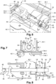
- the hollow shape 96 may be blind or through, as illustrated in the figure 7 .
- the first support 46.1 comprises a longitudinal wall 98 pressed against the first face F44.1 of the wall 44.1 of the first element 42.1 and sized to close the hollow shape 96 when the latter is a through shape. It comprises a through hole to allow the passage of the pivoting control 90, more particularly of the first control axis 94.
- the locking mechanism 40 comprises a trim plate 100 sized to fill the hollow shape 96 as well as a quick-attach system 102 for connecting the trim plate 100 to the wall 44.1 of the first element 42.1 or to the longitudinal wall 98 of the first support 46.1.
- this trim plate 100 has a first face pressed against the longitudinal wall 98 and a second face flush with the second face F44.1' of the wall 44.1 of the first element 42.1 (so as not to alter the aerodynamic performance of the aircraft) when the trim plate 100 is fixed to the longitudinal wall 98.
- the quick-attachment system 102 comprises at least one quarter-turn screw to facilitate the disassembly of the trim plate 100.
- the first adjustment system 74 comprises an anti-return system 104 for blocking in rotation, in at least one direction of rotation, the pivoting control 90 in order to immobilize the anchor point 48 in the adjusted position.
- the non-return system 104 comprises a rotation locking plate comprising a through-hole 106 having a section identical to that of the first end 94.1 and cooperating with the latter, said rotation locking plate being connected to the first support 46.1.
- the non-return system 104 makes it possible to immobilize the pivoting control 90 in both directions of rotation.
- the lining plate and the rotation locking plate form only one single plate.
- the anti-return system 104 comprises a ratchet wheel 108 secured to the pivoting control 90, plus particularly of the first control axis 94, a pawl 110 connected to the first support 46.1 and connected to the latter by a pivoting connection having a pivot axis A110 parallel to the first control axis 94, an elastic return element 112 configured to push the pawl 110 against the ratchet wheel 108 as well as a control cam 114 configured to move the pawl 110 away from the ratchet wheel 108 against the elastic return element 112.
- the control cam 114 is connected to a second control axis substantially parallel to the first control axis 94, said second control axis having an end accessible from the second zone.
- the non-return system 104 is configured to occupy an activated state (visible on the figure 12 ) in which the pawl 110 cooperates with the ratchet wheel 108 in order to immobilize the pivoting control 90 in a direction of rotation as well as a disengaged state (visible on the figure 13 ) in which the pawl 110 is spaced from the ratchet wheel 108 allowing rotation of the pivoting control 90 in both directions of rotation.
- the first rod 52 comprises first and second coaxial sections 52.1, 52.2 as well as a helical connection 88 connecting them.
- the first section 52.1 is integral with the anchor point 48 (connected to the latter by a rigid connection) and connected to the first support 46.1 by a sliding connection 76.
- the second section 52.2 is connected to the first support 46.1 by a pivoting connection 116.
- the first ring 86 is integral with the second section 52.2 and connected to the latter by a rigid connection.
- the helical connection 88 comprises a first part among the first and second sections 52.1, 52.2 which has a first end 118.1 configured to be housed in a hole 118.2 provided at a second end of a second part, different from the first part, among the first and second sections 52.1, 52.2, the first end 118.1 comprising a thread, the hole 118.2 comprising a tapping configured to cooperate with the thread of the first end 118.1 in order to obtain the helical connection.
- the first end 118.1 is provided on the second section 52.2 and the hole 118.2 is provided at the first section 52.1.
- the intermediate part corresponds to the first ring 86, the angle transmission 92 making it possible to convert the pivoting movement of the pivoting control 90 into a pivoting movement of the first ring 86, the helical connection 88 making it possible to convert the pivoting movement of the first ring 86 into a translational movement of the first rod 52.
- the intermediate part comprises the second section 52.2 of the first rod 52.
- the angle transmission 92 makes it possible to convert the pivoting movement of the pivoting control 90 into a pivoting movement of the second section 52.2, the helical connection 88 making it possible to convert the pivoting movement of the second section 52.2 into a translational movement of the first section 52.1 of the first rod 52.
- the centering system 60 and the wedge system 68, connected to the second support 46.2, are positioned on either side of the handle 58.
- each of the second and third links 64, 72 connecting the centering system 60 and the shim system 68 to the second support 46.2 is configured to allow adjustment of the positioning of the centering system 60 and the shim system 68. shim 68 relative to the second support 46.2 in the longitudinal direction.
- the second and third links 64, 72 each comprise an adjustment system similar to the first adjustment system 74 making it possible to adjust the position of the centering system 60 and the shim system 68 relative to the second support 46.2 in the longitudinal direction, as illustrated in the Figures 14 to 17 .
- centering system 60 and the wedge system 68 comprise separate pivoting controls 90.1, 90.2 accessible from hollow shapes 96.1, 96.2 positioned on either side of the handle 58, at the level of the second face F44.2' of the wall 44.2 and filled by removable trim plates 100.1, 100.2.
Landscapes
- Engineering & Computer Science (AREA)
- Mechanical Engineering (AREA)
- Aviation & Aerospace Engineering (AREA)
- Connection Of Plates (AREA)
- Transmission Devices (AREA)
Claims (10)
- Verriegelungsmechanismus, der einen ersten und einen zweiten Bereich (40.1, 40.2) aufweist und so eingerichtet ist, dass er einen verriegelten Zustand, in dem der erste und der zweite Bereich (40.1, 40.2) nahe beieinander gehalten sind, sowie einen entriegelten Zustand einnimmt, in dem sich der erste und der zweite Bereich (40.1, 40.2) in eine Längsrichtung auseinander bewegen können, wobei der erste Bereich (40.1) so eingerichtet ist, dass er auf einem ersten Element (42.1, 42.2) befestigt werden kann, das eine Wand (44.1, 44.2) aufweist, die eine erste Zone und eine zweite Zone trennt, wobei sich der erste Bereich (40.1) in der ersten Zone befindet und einen ersten Träger (46.1) aufweist, der im Betrieb an der Wand (44.1, 44.2) befestigt ist, und wobei der erste Bereich (40.1) wenigstens eine einstellbare Komponente umfasst, die in Längsrichtung eine einstellbare Positionierung bietet und mit dem ersten Träger (46.1) durch eine Verbindung (50, 64, 72) verbunden ist, die eine Stange (52, 62, 70) aufweist, die einen ersten Abschnitt (52.1) aufweist, der fest mit der einstellbaren Komponente verbunden ist; wobei die Verbindung (50, 64, 72) umfasst:- eine Gleitverbindung, die so eingerichtet ist, dass sie es zumindest dem ersten Abschnitt (52.1) der Stange (52, 62, 70) ermöglicht, sich in Bezug auf den ersten Träger (46.1) in Längsrichtung zu verschieben,- ein Einstellsystem (74) mit:dadurch gekennzeichnet, dass das Einstellsystem (74) ein Rücklaufsperrsystem (104) aufweist, um den Schwenkantrieb (90) gegen Drehung in wenigstens eine Drehrichtung zu blockieren.∘ einen Schwenkantrieb (90), der so eingerichtet ist, dass er um sich selbst schwenkt, die Wand (44.1, 44.2) durchdringt und ein erstes Ende aufweist, das im Betrieb von der zweiten Zone aus zugänglich ist,∘ ein Zwischenstück, das so eingerichtet ist, dass es um sich selbst schwenkt,∘ ein Umlenkgetriebe (92), mit dem eine Schwenkbewegung des Schwenkantriebs (90) in eine Schwenkbewegung des Zwischenstücks umwandelbar ist,∘ eine Schneckenverbindung (88), die so eingerichtet ist, dass sie eine Schwenkbewegung des Zwischenstücks in eine Translationsbewegung von wenigstens dem ersten Abschnitt (52.1) der Stange (52, 62, 70) umwandelt,
- Verriegelungsmechanismus nach Anspruch 1, dadurch gekennzeichnet, dass das Zwischenstück ein erster Ring (86) ist, der um die Stange (52) herum angeordnet ist und eine zylindrische Innenfläche aufweist, und dass die Schneckenverbindung (88) wenigstens ein Innengewinde an der zylindrischen Innenfläche des ersten Rings (86) sowie wenigstens ein Schneckengewinde an der Stange (52) aufweist, wobei das Innengewinde und das Schneckengewinde so eingerichtet sind, dass sie zusammenwirken, um die Schneckenverbindung (88) zu erhalten, wobei das Umlenkgetriebe (92) es ermöglicht, die Schwenkbewegung des Schwenkantriebs (90) in eine Schwenkbewegung des ersten Rings (86) umzuwandeln.
- Verriegelungsmechanismus nach Anspruch 1, dadurch gekennzeichnet, dass die Stange (52) einen zweiten Abschnitt (52.2) umfasst, der koaxial zum ersten Abschnitt (52.1) verläuft, und dass das Zwischenstück den zweiten Abschnitt (52.2) der Stange (52) umfasst, wobei das Umlenkgetriebe (92) es ermöglicht, die Schwenkbewegung des Schwenkantriebs (90) in eine Schwenkbewegung des zweiten Abschnitts (52.2) umzuwandeln, und wobei die Schneckenverbindung (88) es ermöglicht, die Schwenkbewegung des zweiten Abschnitts (52.2) in eine Translationsbewegung des ersten Abschnitts (52.1) der Stange (52) umzuwandeln.
- Verriegelungsmechanismus nach einem der vorhergehenden Ansprüche, dadurch gekennzeichnet, dass der erste Bereich (40.1) eine Dreh-Gleitverbindung, die die Stange (52) und den ersten Träger (46.1) verbindet, sowie ein System zur Rotationssicherung der Stange (52) aufweist.
- Verriegelungsmechanismus nach einem der vorhergehenden Ansprüche, dadurch gekennzeichnet, dass das Rücklaufsperrsystem (104) ein Sperrklinkenrad (108), das fest mit dem Schwenkantrieb (90) verbunden ist, eine Sperrklinke (110), die mit dem ersten Träger (46. 1) durch eine Schwenkverbindung verbunden ist, ein elastisches Rückstellelement (112), das so eingerichtet ist, dass es die Sperrklinke (110) gegen das Sperrklinkenrad (108) drückt, sowie einen Steuernocken (114) aufweist, der so eingerichtet ist, dass er die Sperrklinke (110) gegen das elastische Rückstellelement (112) von dem Sperrklinkenrad (108) wegbewegt.
- Verriegelungsmechanismus nach einem der vorhergehenden Ansprüche, dadurch gekennzeichnet, dass der Schwenkantrieb (90) eine erste Antriebsachse (94) aufweist, mit einem ersten Ende (94.1), das von der zweiten Zone aus zugänglich ist, und mit einer Seitenfläche, die an dem ersten Ende (94.1) mit wenigstens einer Abflachung versehen ist, um die erste Antriebsachse (94) um sich selbst drehen zu lassen, und dass das Rücklaufsperrsystem (104) eine Drehsperrplatte umfasst, die eine Durchgangsöffnung (106) mit einem Querschnitt aufweist, der mit dem des ersten Endes (94.1) identisch ist und mit diesem zusammenwirkt, wobei die Drehsperrplatte mit dem ersten Träger (46.1) verbunden ist.
- Verriegelungsmechanismus nach einem der vorhergehenden Ansprüche, dadurch gekennzeichnet, dass der Verriegelungsmechanismus mehrere einstellbare Komponenten aufweist, darunter einen Ankerpunkt (48), der so eingerichtet ist, dass er mit einem Haken (56) zusammenwirkt, wenigstens ein Zentriersystem (60), das so eingerichtet ist, dass es die Positionierung des ersten und des zweiten Bereichs (40.1, 40.2) relativ zueinander ermöglicht, und wenigstens ein Abstandsystem (68), das so eingerichtet ist, dass es die Aufrechterhaltung eines gegebenen Abstands zwischen dem ersten und dem zweiten Bereich (40.1, 40.2) im verriegelten Zustand ermöglicht.
- Luftfahrzeug mit wenigstens einem beweglichen Element (42.1, 42.2), das eine Wand (44.1, 44.2) umfasst, die eine erste Zone und eine zweite Zone voneinander trennt und eine erste Seite (F44.1, F44.2) aufweist, die der ersten Zone zugewandt ist, sowie eine zweite Seite (F44.1', F44.2'), die der zweiten Zone zugewandt ist, sowie wenigstens einen Verriegelungsmechanismus nach einem der vorhergehenden Ansprüche, der in der ersten Zone angeordnet ist und es ermöglicht, das bewegliche Element (4.21, 42.2) im verriegelten Zustand in einer bestimmten Position zu halten.
- Luftfahrzeug nach dem vorhergehenden Anspruch,
dadurch gekennzeichnet, dass die zweite Seite (F44.1') der Wand (44.1) jeweils für den Schwenkantrieb (90) eine vertiefte Form (96) aufweist, die so eingerichtet ist, dass sie einen Teil des Schwenkantriebs (90) aufnimmt, der von der zweiten Zone aus zugänglich ist, wobei der Schwenkantrieb (90) eine Endfläche (F94) aufweist, die im Wesentlichen komplanar mit der zweiten Seite (F44.1') der Wand (44.1) ist. - Flugzeug nach dem vorhergehenden Anspruch, dadurch gekennzeichnet, dass der Verriegelungsmechanismus (40) für die vertiefte Form (96) jeweils eine Verkleidungsplatte (100) aufweist, die so bemessen ist, dass sie die vertiefte Form (96) ausfüllt, sowie ein Schnellbefestigungssystem (102) aufweist, um die Verkleidungsplatte (100) mit der Wand (44.1) oder einem Träger (46.1) des Verriegelungsmechanismus (40) zu verbinden, wobei die Verkleidungsplatte (100) eine Seite aufweist, die mit der zweiten Seite (F44.1') der Wand (44.1) bündig ist, wenn die Verkleidungsplatte (100) mit der Wand (44.1) oder dem Träger (46.1) verbunden ist.
Applications Claiming Priority (1)
| Application Number | Priority Date | Filing Date | Title |
|---|---|---|---|
| FR2201625A FR3132920A1 (fr) | 2022-02-24 | 2022-02-24 | Mécanisme de verrouillage d’au moins un élément mobile situé dans une première zone et comportant un composant réglable depuis une deuxième zone, aéronef comprenant au moins un tel mécanisme de verrouillage |
Publications (2)
| Publication Number | Publication Date |
|---|---|
| EP4234851A1 EP4234851A1 (de) | 2023-08-30 |
| EP4234851B1 true EP4234851B1 (de) | 2024-10-30 |
Family
ID=81851093
Family Applications (1)
| Application Number | Title | Priority Date | Filing Date |
|---|---|---|---|
| EP23155707.5A Active EP4234851B1 (de) | 2022-02-24 | 2023-02-09 | Verriegelungsmechanismus für mindestens ein in einem ersten bereich angeordnetes bewegliches element mit einem aus einem zweiten bereich verstellbaren bauteil, luftfahrzeug, das mindestens einen solchen verriegelungsmechanismus umfasst |
Country Status (3)
| Country | Link |
|---|---|
| US (1) | US12486698B2 (de) |
| EP (1) | EP4234851B1 (de) |
| FR (1) | FR3132920A1 (de) |
Family Cites Families (13)
| Publication number | Priority date | Publication date | Assignee | Title |
|---|---|---|---|---|
| US2767007A (en) * | 1953-06-22 | 1956-10-16 | Nat Lock Co | Refrigerator latch |
| US4158463A (en) * | 1977-08-26 | 1979-06-19 | Hartwell Corporation | Adjustable keeper for rotary latches |
| US4183564A (en) * | 1978-03-01 | 1980-01-15 | Hartwell Corporation | Externally accessible adjuster for flush latches |
| US4538843A (en) * | 1983-03-04 | 1985-09-03 | The Boeing Company | Preloaded latch |
| US4798408A (en) * | 1986-04-23 | 1989-01-17 | Rexnord Inc. | Adjustable latching mechanism |
| US4852923A (en) | 1987-02-27 | 1989-08-01 | Rexnord Holdings Inc. | Vertical access adjustable latching mechanism externally accessible adjustable keeper mechanism |
| US4906037A (en) * | 1987-09-08 | 1990-03-06 | V.S.I. Corp. | Externally accessible, clutching adjustable keeper mechanism |
| US5016931A (en) * | 1989-06-20 | 1991-05-21 | The Hartwell Corporation | Latching mechanism having a pre-adjusted load |
| US7261356B1 (en) * | 2004-10-15 | 2007-08-28 | Ricky Taylor | Trailer |
| US7270029B1 (en) * | 2006-07-27 | 2007-09-18 | Ford Global Technologies, Llc | Passive entry side door latch release system |
| US8113551B2 (en) * | 2007-06-13 | 2012-02-14 | Avibank Manufacturing, Inc. | Radome latch and keeper |
| US9273488B1 (en) * | 2013-07-15 | 2016-03-01 | Avibank Manufacturing, Inc. | Positive locking keeper |
| US11866189B2 (en) * | 2020-03-26 | 2024-01-09 | Hartwell Corporation | Latching system with movable anti-shear mechanism |
-
2022
- 2022-02-24 FR FR2201625A patent/FR3132920A1/fr not_active Ceased
-
2023
- 2023-02-09 EP EP23155707.5A patent/EP4234851B1/de active Active
- 2023-02-22 US US18/172,887 patent/US12486698B2/en active Active
Also Published As
| Publication number | Publication date |
|---|---|
| US20230265694A1 (en) | 2023-08-24 |
| FR3132920A1 (fr) | 2023-08-25 |
| EP4234851A1 (de) | 2023-08-30 |
| US12486698B2 (en) | 2025-12-02 |
Similar Documents
| Publication | Publication Date | Title |
|---|---|---|
| EP2674362B1 (de) | Bolzenschließvorrichtung | |
| EP2683897B1 (de) | Vorrichtung zur unterstützung des öffnens eines relatif zum rand eines rahmens schwenkbar montierten verschlusselementes | |
| FR2826625A1 (fr) | Dispositif de direction telescopique retractable | |
| EP3553331A1 (de) | Verbindungsvorrichtung, die zwischen mindestens zwei teilen schwenkbar ist, luftfahrzeug, das eine abdeckung umfasst, die mit dieser schwenkbaren verbindungsvorrichtung ausgestattet ist | |
| FR3029957A1 (fr) | Dispositif de deverrouillage pour un capot de vehicule | |
| EP0024976A1 (de) | Vorrichtung zum Regeln der relativen Neigung zweier Teile, insbesondere der zwei Teile eines Fahrzeugsitzes | |
| EP1405762A1 (de) | Kfz-Scheinwerfer mit einem von dem Gehäuse gestützten Gelenkelement | |
| EP0436452A2 (de) | Tür- oder Fensterbeschlag mit Mitteln zum Halten der Flügel in geöffnetem Zustand | |
| EP1673530B1 (de) | Schubumkehrerverriegelung mit verriegelungsvorrichtung | |
| FR2843725A1 (fr) | Agencement pour l'accouplement d'une tige de commande d'un servomoteur | |
| FR2471793A1 (fr) | Dispositif de blocage d'une extremite d'une ceinture de securite pour vehicules automobiles, combine avec une glissiere d'un siege | |
| EP4234851A1 (de) | Verriegelungsmechanismus für mindestens ein in einem ersten bereich angeordnetes bewegliches element mit einem aus einem zweiten bereich verstellbaren bauteil, luftfahrzeug, das mindestens einen solchen verriegelungsmechanismus umfasst | |
| EP1907654B1 (de) | Vorrichtung zur steuerung des verriegelns und entriegelns einer flugzeugtür und diese enthaltende flugzeugtür | |
| EP0869243B1 (de) | Schiebetürbeschlag | |
| CA3036788C (fr) | Procede de manoeuvre d'un atterrisseur d'aeronef entre une position deployee et une position retractee | |
| EP2516778A2 (de) | Blendenvorrichtung und zugehörige anordnung | |
| EP4676832A1 (de) | Aeronautische förder- und absteigvorrichtung | |
| FR2678314A1 (fr) | Dispositif d'assistance a la fermeture pour portiere de vehicule automobile. | |
| EP3683150B1 (de) | Verbindungsvorrichtung, die zwischen mindestens zwei teilen schwenkbar ist, luftfahrzeug, das eine abdeckung umfasst, die mit dieser schwenkbaren verbindungsvorrichtung ausgestattet ist | |
| FR2502676A3 (fr) | Paumelle degondable pour portes de vehicules automobiles | |
| FR2664864A1 (fr) | Trappe d'obturation de l'acces au reservoir de carburant d'un vehicule automobile. | |
| EP1407909B1 (de) | Schliesseinrichtung für eine in einer Kraftfahrzeugkarrosserie angeordnete Öffnung mit einem beweglichen und verschwenkbaren Deckel | |
| FR2464883A1 (fr) | Train d'atterrissage relevable et orientable pour aerodyne, en particulier pour helicoptere | |
| FR2996181A1 (fr) | Glissiere a faible pas de verrouillage et siege de vehicule automobile comportant une telle glissiere | |
| FR2618517A1 (fr) | Robinet-clapet |
Legal Events
| Date | Code | Title | Description |
|---|---|---|---|
| PUAI | Public reference made under article 153(3) epc to a published international application that has entered the european phase |
Free format text: ORIGINAL CODE: 0009012 |
|
| STAA | Information on the status of an ep patent application or granted ep patent |
Free format text: STATUS: THE APPLICATION HAS BEEN PUBLISHED |
|
| AK | Designated contracting states |
Kind code of ref document: A1 Designated state(s): AL AT BE BG CH CY CZ DE DK EE ES FI FR GB GR HR HU IE IS IT LI LT LU LV MC ME MK MT NL NO PL PT RO RS SE SI SK SM TR |
|
| STAA | Information on the status of an ep patent application or granted ep patent |
Free format text: STATUS: REQUEST FOR EXAMINATION WAS MADE |
|
| 17P | Request for examination filed |
Effective date: 20240208 |
|
| RBV | Designated contracting states (corrected) |
Designated state(s): AL AT BE BG CH CY CZ DE DK EE ES FI FR GB GR HR HU IE IS IT LI LT LU LV MC ME MK MT NL NO PL PT RO RS SE SI SK SM TR |
|
| GRAP | Despatch of communication of intention to grant a patent |
Free format text: ORIGINAL CODE: EPIDOSNIGR1 |
|
| STAA | Information on the status of an ep patent application or granted ep patent |
Free format text: STATUS: GRANT OF PATENT IS INTENDED |
|
| INTG | Intention to grant announced |
Effective date: 20240531 |
|
| GRAS | Grant fee paid |
Free format text: ORIGINAL CODE: EPIDOSNIGR3 |
|
| GRAA | (expected) grant |
Free format text: ORIGINAL CODE: 0009210 |
|
| STAA | Information on the status of an ep patent application or granted ep patent |
Free format text: STATUS: THE PATENT HAS BEEN GRANTED |
|
| RIN1 | Information on inventor provided before grant (corrected) |
Inventor name: VIGNOBOUL, BENJAMIN Inventor name: CAZEAUX, LAURENT Inventor name: BROCHARD, WOLFGANG |
|
| AK | Designated contracting states |
Kind code of ref document: B1 Designated state(s): AL AT BE BG CH CY CZ DE DK EE ES FI FR GB GR HR HU IE IS IT LI LT LU LV MC ME MK MT NL NO PL PT RO RS SE SI SK SM TR |
|
| REG | Reference to a national code |
Ref country code: GB Ref legal event code: FG4D Free format text: NOT ENGLISH |
|
| REG | Reference to a national code |
Ref country code: CH Ref legal event code: EP |
|
| REG | Reference to a national code |
Ref country code: IE Ref legal event code: FG4D Free format text: LANGUAGE OF EP DOCUMENT: FRENCH |
|
| REG | Reference to a national code |
Ref country code: DE Ref legal event code: R096 Ref document number: 602023000835 Country of ref document: DE |
|
| REG | Reference to a national code |
Ref country code: LT Ref legal event code: MG9D |
|
| REG | Reference to a national code |
Ref country code: NL Ref legal event code: MP Effective date: 20241030 |
|
| PG25 | Lapsed in a contracting state [announced via postgrant information from national office to epo] |
Ref country code: HR Free format text: LAPSE BECAUSE OF FAILURE TO SUBMIT A TRANSLATION OF THE DESCRIPTION OR TO PAY THE FEE WITHIN THE PRESCRIBED TIME-LIMIT Effective date: 20241030 Ref country code: IS Free format text: LAPSE BECAUSE OF FAILURE TO SUBMIT A TRANSLATION OF THE DESCRIPTION OR TO PAY THE FEE WITHIN THE PRESCRIBED TIME-LIMIT Effective date: 20250228 Ref country code: PT Free format text: LAPSE BECAUSE OF FAILURE TO SUBMIT A TRANSLATION OF THE DESCRIPTION OR TO PAY THE FEE WITHIN THE PRESCRIBED TIME-LIMIT Effective date: 20250228 |
|
| PG25 | Lapsed in a contracting state [announced via postgrant information from national office to epo] |
Ref country code: FI Free format text: LAPSE BECAUSE OF FAILURE TO SUBMIT A TRANSLATION OF THE DESCRIPTION OR TO PAY THE FEE WITHIN THE PRESCRIBED TIME-LIMIT Effective date: 20241030 Ref country code: NL Free format text: LAPSE BECAUSE OF FAILURE TO SUBMIT A TRANSLATION OF THE DESCRIPTION OR TO PAY THE FEE WITHIN THE PRESCRIBED TIME-LIMIT Effective date: 20241030 |
|
| REG | Reference to a national code |
Ref country code: AT Ref legal event code: MK05 Ref document number: 1737015 Country of ref document: AT Kind code of ref document: T Effective date: 20241030 |
|
| PG25 | Lapsed in a contracting state [announced via postgrant information from national office to epo] |
Ref country code: BG Free format text: LAPSE BECAUSE OF FAILURE TO SUBMIT A TRANSLATION OF THE DESCRIPTION OR TO PAY THE FEE WITHIN THE PRESCRIBED TIME-LIMIT Effective date: 20241030 |
|
| PG25 | Lapsed in a contracting state [announced via postgrant information from national office to epo] |
Ref country code: ES Free format text: LAPSE BECAUSE OF FAILURE TO SUBMIT A TRANSLATION OF THE DESCRIPTION OR TO PAY THE FEE WITHIN THE PRESCRIBED TIME-LIMIT Effective date: 20241030 |
|
| PG25 | Lapsed in a contracting state [announced via postgrant information from national office to epo] |
Ref country code: NO Free format text: LAPSE BECAUSE OF FAILURE TO SUBMIT A TRANSLATION OF THE DESCRIPTION OR TO PAY THE FEE WITHIN THE PRESCRIBED TIME-LIMIT Effective date: 20250130 |
|
| PG25 | Lapsed in a contracting state [announced via postgrant information from national office to epo] |
Ref country code: AT Free format text: LAPSE BECAUSE OF FAILURE TO SUBMIT A TRANSLATION OF THE DESCRIPTION OR TO PAY THE FEE WITHIN THE PRESCRIBED TIME-LIMIT Effective date: 20241030 Ref country code: LV Free format text: LAPSE BECAUSE OF FAILURE TO SUBMIT A TRANSLATION OF THE DESCRIPTION OR TO PAY THE FEE WITHIN THE PRESCRIBED TIME-LIMIT Effective date: 20241030 Ref country code: GR Free format text: LAPSE BECAUSE OF FAILURE TO SUBMIT A TRANSLATION OF THE DESCRIPTION OR TO PAY THE FEE WITHIN THE PRESCRIBED TIME-LIMIT Effective date: 20250131 |
|
| PG25 | Lapsed in a contracting state [announced via postgrant information from national office to epo] |
Ref country code: PL Free format text: LAPSE BECAUSE OF FAILURE TO SUBMIT A TRANSLATION OF THE DESCRIPTION OR TO PAY THE FEE WITHIN THE PRESCRIBED TIME-LIMIT Effective date: 20241030 |
|
| PG25 | Lapsed in a contracting state [announced via postgrant information from national office to epo] |
Ref country code: RS Free format text: LAPSE BECAUSE OF FAILURE TO SUBMIT A TRANSLATION OF THE DESCRIPTION OR TO PAY THE FEE WITHIN THE PRESCRIBED TIME-LIMIT Effective date: 20250130 |
|
| PG25 | Lapsed in a contracting state [announced via postgrant information from national office to epo] |
Ref country code: SM Free format text: LAPSE BECAUSE OF FAILURE TO SUBMIT A TRANSLATION OF THE DESCRIPTION OR TO PAY THE FEE WITHIN THE PRESCRIBED TIME-LIMIT Effective date: 20241030 |
|
| PG25 | Lapsed in a contracting state [announced via postgrant information from national office to epo] |
Ref country code: DK Free format text: LAPSE BECAUSE OF FAILURE TO SUBMIT A TRANSLATION OF THE DESCRIPTION OR TO PAY THE FEE WITHIN THE PRESCRIBED TIME-LIMIT Effective date: 20241030 |
|
| PG25 | Lapsed in a contracting state [announced via postgrant information from national office to epo] |
Ref country code: EE Free format text: LAPSE BECAUSE OF FAILURE TO SUBMIT A TRANSLATION OF THE DESCRIPTION OR TO PAY THE FEE WITHIN THE PRESCRIBED TIME-LIMIT Effective date: 20241030 |
|
| PG25 | Lapsed in a contracting state [announced via postgrant information from national office to epo] |
Ref country code: RO Free format text: LAPSE BECAUSE OF FAILURE TO SUBMIT A TRANSLATION OF THE DESCRIPTION OR TO PAY THE FEE WITHIN THE PRESCRIBED TIME-LIMIT Effective date: 20241030 |
|
| PG25 | Lapsed in a contracting state [announced via postgrant information from national office to epo] |
Ref country code: SK Free format text: LAPSE BECAUSE OF FAILURE TO SUBMIT A TRANSLATION OF THE DESCRIPTION OR TO PAY THE FEE WITHIN THE PRESCRIBED TIME-LIMIT Effective date: 20241030 |
|
| PG25 | Lapsed in a contracting state [announced via postgrant information from national office to epo] |
Ref country code: CZ Free format text: LAPSE BECAUSE OF FAILURE TO SUBMIT A TRANSLATION OF THE DESCRIPTION OR TO PAY THE FEE WITHIN THE PRESCRIBED TIME-LIMIT Effective date: 20241030 |
|
| PG25 | Lapsed in a contracting state [announced via postgrant information from national office to epo] |
Ref country code: IT Free format text: LAPSE BECAUSE OF FAILURE TO SUBMIT A TRANSLATION OF THE DESCRIPTION OR TO PAY THE FEE WITHIN THE PRESCRIBED TIME-LIMIT Effective date: 20241030 |
|
| REG | Reference to a national code |
Ref country code: DE Ref legal event code: R097 Ref document number: 602023000835 Country of ref document: DE |
|
| PLBE | No opposition filed within time limit |
Free format text: ORIGINAL CODE: 0009261 |
|
| STAA | Information on the status of an ep patent application or granted ep patent |
Free format text: STATUS: NO OPPOSITION FILED WITHIN TIME LIMIT |
|
| PG25 | Lapsed in a contracting state [announced via postgrant information from national office to epo] |
Ref country code: SE Free format text: LAPSE BECAUSE OF FAILURE TO SUBMIT A TRANSLATION OF THE DESCRIPTION OR TO PAY THE FEE WITHIN THE PRESCRIBED TIME-LIMIT Effective date: 20241030 |
|
| PG25 | Lapsed in a contracting state [announced via postgrant information from national office to epo] |
Ref country code: MC Free format text: LAPSE BECAUSE OF FAILURE TO SUBMIT A TRANSLATION OF THE DESCRIPTION OR TO PAY THE FEE WITHIN THE PRESCRIBED TIME-LIMIT Effective date: 20241030 |
|
| 26N | No opposition filed |
Effective date: 20250731 |
|
| PG25 | Lapsed in a contracting state [announced via postgrant information from national office to epo] |
Ref country code: LU Free format text: LAPSE BECAUSE OF NON-PAYMENT OF DUE FEES Effective date: 20250209 |
|
| REG | Reference to a national code |
Ref country code: BE Ref legal event code: MM Effective date: 20250228 |
|
| PG25 | Lapsed in a contracting state [announced via postgrant information from national office to epo] |
Ref country code: BE Free format text: LAPSE BECAUSE OF NON-PAYMENT OF DUE FEES Effective date: 20250228 |
|
| PG25 | Lapsed in a contracting state [announced via postgrant information from national office to epo] |
Ref country code: IE Free format text: LAPSE BECAUSE OF NON-PAYMENT OF DUE FEES Effective date: 20250209 |
|
| PGFP | Annual fee paid to national office [announced via postgrant information from national office to epo] |
Ref country code: DE Payment date: 20260218 Year of fee payment: 4 |
|
| PGFP | Annual fee paid to national office [announced via postgrant information from national office to epo] |
Ref country code: FR Payment date: 20260219 Year of fee payment: 4 |