EP4234757A1 - Wafer carrying mechanism and semiconductor process apparatus - Google Patents
Wafer carrying mechanism and semiconductor process apparatus Download PDFInfo
- Publication number
- EP4234757A1 EP4234757A1 EP21885047.7A EP21885047A EP4234757A1 EP 4234757 A1 EP4234757 A1 EP 4234757A1 EP 21885047 A EP21885047 A EP 21885047A EP 4234757 A1 EP4234757 A1 EP 4234757A1
- Authority
- EP
- European Patent Office
- Prior art keywords
- heater
- plate
- cooling structure
- support plate
- carrying mechanism
- Prior art date
- Legal status (The legal status is an assumption and is not a legal conclusion. Google has not performed a legal analysis and makes no representation as to the accuracy of the status listed.)
- Granted
Links
Images


Classifications
-
- H—ELECTRICITY
- H10—SEMICONDUCTOR DEVICES; ELECTRIC SOLID-STATE DEVICES NOT OTHERWISE PROVIDED FOR
- H10P—GENERIC PROCESSES OR APPARATUS FOR THE MANUFACTURE OR TREATMENT OF DEVICES COVERED BY CLASS H10
- H10P72/00—Handling or holding of wafers, substrates or devices during manufacture or treatment thereof
- H10P72/04—Apparatus for manufacture or treatment
- H10P72/0431—Apparatus for thermal treatment
- H10P72/0432—Apparatus for thermal treatment mainly by conduction
-
- C—CHEMISTRY; METALLURGY
- C23—COATING METALLIC MATERIAL; COATING MATERIAL WITH METALLIC MATERIAL; CHEMICAL SURFACE TREATMENT; DIFFUSION TREATMENT OF METALLIC MATERIAL; COATING BY VACUUM EVAPORATION, BY SPUTTERING, BY ION IMPLANTATION OR BY CHEMICAL VAPOUR DEPOSITION, IN GENERAL; INHIBITING CORROSION OF METALLIC MATERIAL OR INCRUSTATION IN GENERAL
- C23C—COATING METALLIC MATERIAL; COATING MATERIAL WITH METALLIC MATERIAL; SURFACE TREATMENT OF METALLIC MATERIAL BY DIFFUSION INTO THE SURFACE, BY CHEMICAL CONVERSION OR SUBSTITUTION; COATING BY VACUUM EVAPORATION, BY SPUTTERING, BY ION IMPLANTATION OR BY CHEMICAL VAPOUR DEPOSITION, IN GENERAL
- C23C14/00—Coating by vacuum evaporation, by sputtering or by ion implantation of the coating forming material
- C23C14/22—Coating by vacuum evaporation, by sputtering or by ion implantation of the coating forming material characterised by the process of coating
- C23C14/50—Substrate holders
-
- C—CHEMISTRY; METALLURGY
- C23—COATING METALLIC MATERIAL; COATING MATERIAL WITH METALLIC MATERIAL; CHEMICAL SURFACE TREATMENT; DIFFUSION TREATMENT OF METALLIC MATERIAL; COATING BY VACUUM EVAPORATION, BY SPUTTERING, BY ION IMPLANTATION OR BY CHEMICAL VAPOUR DEPOSITION, IN GENERAL; INHIBITING CORROSION OF METALLIC MATERIAL OR INCRUSTATION IN GENERAL
- C23C—COATING METALLIC MATERIAL; COATING MATERIAL WITH METALLIC MATERIAL; SURFACE TREATMENT OF METALLIC MATERIAL BY DIFFUSION INTO THE SURFACE, BY CHEMICAL CONVERSION OR SUBSTITUTION; COATING BY VACUUM EVAPORATION, BY SPUTTERING, BY ION IMPLANTATION OR BY CHEMICAL VAPOUR DEPOSITION, IN GENERAL
- C23C14/00—Coating by vacuum evaporation, by sputtering or by ion implantation of the coating forming material
- C23C14/22—Coating by vacuum evaporation, by sputtering or by ion implantation of the coating forming material characterised by the process of coating
- C23C14/54—Controlling or regulating the coating process
- C23C14/541—Heating or cooling of the substrates
-
- H—ELECTRICITY
- H01—ELECTRIC ELEMENTS
- H01J—ELECTRIC DISCHARGE TUBES OR DISCHARGE LAMPS
- H01J37/00—Discharge tubes with provision for introducing objects or material to be exposed to the discharge, e.g. for the purpose of examination or processing thereof
- H01J37/32—Gas-filled discharge tubes
- H01J37/32431—Constructional details of the reactor
- H01J37/32715—Workpiece holder
- H01J37/32724—Temperature
-
- H—ELECTRICITY
- H10—SEMICONDUCTOR DEVICES; ELECTRIC SOLID-STATE DEVICES NOT OTHERWISE PROVIDED FOR
- H10P—GENERIC PROCESSES OR APPARATUS FOR THE MANUFACTURE OR TREATMENT OF DEVICES COVERED BY CLASS H10
- H10P72/00—Handling or holding of wafers, substrates or devices during manufacture or treatment thereof
- H10P72/04—Apparatus for manufacture or treatment
- H10P72/0431—Apparatus for thermal treatment
- H10P72/0434—Apparatus for thermal treatment mainly by convection
-
- H—ELECTRICITY
- H10—SEMICONDUCTOR DEVICES; ELECTRIC SOLID-STATE DEVICES NOT OTHERWISE PROVIDED FOR
- H10P—GENERIC PROCESSES OR APPARATUS FOR THE MANUFACTURE OR TREATMENT OF DEVICES COVERED BY CLASS H10
- H10P72/00—Handling or holding of wafers, substrates or devices during manufacture or treatment thereof
- H10P72/70—Handling or holding of wafers, substrates or devices during manufacture or treatment thereof for supporting or gripping
- H10P72/76—Handling or holding of wafers, substrates or devices during manufacture or treatment thereof for supporting or gripping using mechanical means, e.g. clamps or pinches
- H10P72/7604—Handling or holding of wafers, substrates or devices during manufacture or treatment thereof for supporting or gripping using mechanical means, e.g. clamps or pinches the wafers being placed on a susceptor, stage or support
- H10P72/7624—Handling or holding of wafers, substrates or devices during manufacture or treatment thereof for supporting or gripping using mechanical means, e.g. clamps or pinches the wafers being placed on a susceptor, stage or support characterised by the mechanical construction of the susceptor, stage or support
Definitions
- the present application relates to the field of semiconductor process apparatuses, and in particular, to a wafer carrying mechanism and a semiconductor process apparatus.
- a carrying plate needs to be used to heat a wafer to a certain process temperature, and the carrying plate needs to have the capability to regulate the wafer temperature in a high temperature state, that is, the carrying plate not only can heat the wafer, but also can cool the wafer when needed.
- the cooling capacity requirements on the carrying plate differ for different processes (especially the high-temperature process), for example, there are processes that only require the carrying plate to heat the wafer, and there are processes that require the carrying plate to have a strong cooling capacity. In general, it is difficult to meet the needs of different processes using the same carrying plate.
- a first objective of the present application is to provide a wafer carrying mechanism to solve the technical problem that existing wafer carrying mechanisms have difficulty in meeting the needs of various high-temperature processes.
- a wafer carrying mechanism provided by the present application is used for a semiconductor process apparatus, the wafer carrying mechanism is disposed in a process chamber of the semiconductor process apparatus, the wafer carrying mechanism includes a mounting support, a carrying plate, a heater, a cooling structure, and a distance adjusting assembly, wherein the carrying plate is disposed on the heater for carrying a wafer; the heater is disposed on the mounting support, and an accommodating space is formed between the heater and the mounting support; the cooling structure is located in the accommodating space for cooling the heater; and the distance adjusting assembly is separately connected to the mounting support and the cooling structure for adjusting a vertical distance between the cooling structure and the heater.
- the mounting support includes a flange plate, and a support plate, wherein the flange plate is connected to the heater, and the accommodating space is formed between the flange plate and the heater; the support plate is connected to the flange plate, and at least a portion of the support plate is located in the accommodating space and connected to the cooling structure for supporting the cooling structure; and the distance adjusting assembly includes a first distance adjusting piece and/or a second distance adjusting piece, the cooling structure is connected to the support plate by the first distance adjusting piece, and the first distance adjusting piece is used for adjusting a vertical distance between the cooling structure and the support plate; and/or the support plate is connected to the flange plate by the second distance adjusting piece, and the second distance adjusting piece is used for adjusting a vertical distance between the support plate and the heater.
- the first distance adjusting piece includes threaded rods, nuts, and washers, wherein there are a plurality of threaded rods, and the threaded rods are arranged at intervals along the circumference of the support plate; each threaded rod is vertically disposed, and an upper end of the threaded rod is fixedly connected to the cooling structure; first unthreaded holes are provided at positions corresponding to the threaded rods on the support plate, and the threaded rods penetrate through the first unthreaded holes;
- the flange plate is provided with a central through hole, and a first connecting portion is provided on a hole wall of the central through hole; a portion of the support plate is located in the central through hole; a second connecting portion is provided on an outer peripheral wall of the support plate; the second connecting portion and the first connecting portion are disposed in a superimposing mode, and the second connecting portion is located under the first connecting portion;
- a connecting wall extending in the direction of the heater is provided on the flange plate and at an edge of the flange plate, the connecting wall is fixedly connected to the heater, and the accommodating space is formed between an inner peripheral surface of the connecting wall, a lower surface of the heater and an upper surface of the flange plate.
- the wafer carrying mechanism further includes a pressing ring
- the pressing ring includes an annular body fixedly connected to the heater and surrounding the carrying plate, and pressing teeth disposed in the annular body and protruding relative to an inner peripheral surface of the annular body, wherein there are a plurality of pressing teeth, and the pressing teeth are arranged at intervals along the circumference of the annular body, at least a portion of each of the pressing teeth being elastically superimposed on the carrying plate for pressing the carrying plate against the heater.
- the vertical distance between the cooling structure and the heater is greater than or equal to 0.5 mm and less than or equal to 4 mm.
- the cooling structure includes a cooling screen, and a cooling plate connected to a bottom of the cooling screen, wherein the cooling plate is provided with a flow channel, the flow channel is used for delivering a cooling liquid, and a radial dimension of the cooling screen is greater than or equal to a radial dimension of the carrying plate.
- the heater includes a heater body, and a heating wire embedded in the heater body.
- the vertical distance between the cooling structure and the heater is adjusted by means of the distance adjusting assembly separately connected to the mounting support and the cooling structure.
- the heat conduction efficiency of gas be adjusted to enable adjustment of the cooling capacity, thereby meeting the needs of different high-temperature processes, but also the cooling structure and the heater are made in a non-direct contact state, in this way, during use of the wafer carrying mechanism, the risk of shattering of the carrying plate by the heater due to sudden cooling of the cooling structure can be avoided, thus ensuring that the carrying plate can always be cooled at high temperature, and making the wafer carrying mechanism more advantageous in high-temperature processes.
- a second objective of the present application is to provide a semiconductor process apparatus to solve the technical problem that existing semiconductor process apparatuses have difficulty in meeting the needs of different high-temperature processes.
- the semiconductor process apparatus includes a process chamber and the aforementioned wafer carrying mechanism, the wafer carrying mechanism being disposed within the process chamber.
- the semiconductor process apparatus provides the aforementioned wafer carrying mechanism provided by the present application within the process chamber of the semiconductor process apparatus, the semiconductor process apparatus accordingly has all the advantages of the aforementioned wafer carrying mechanism, which are not described in any further detail herein.
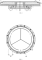
- FIG. 1 is a cross-sectional view of a structure of a wafer carrying mechanism according to an embodiment when a wafer is carried.
- the present embodiment provides a wafer carrying mechanism used for a semiconductor process apparatus, specifically, the wafer carrying mechanism is disposed in a process chamber of the semiconductor process apparatus, the wafer carrying mechanism includes a mounting support 100, a carrying plate 200, a heater 300, a cooling structure 400, and a distance adjusting assembly, wherein the carrying plate 200 is disposed on the heater 300 for carrying a wafer 900, optionally, a lower surface of the carrying plate 200 is attached to an upper surface of the heater 300 to improve heat conduction efficiency of the heater 300.
- the mounting support 100 is fixedly disposed in the process chamber, the heater 300 is disposed on the mounting support 100, and an accommodating space is formed between the heater 300 and the mounting support 100; the cooling structure 400 is located within the accommodating space for cooling the heater 300.
- the heat generated by heating of the heater 300 can be transferred directly to the carrying plate 200 to provide the desired temperature of the wafer 900 under a current high-temperature process; the cooling structure 400 acts as a heat sink for the carrying plate 200, however, the heater 300 is what the cooling structure 400 directly affects, that is, the carrying plate 200 is indirectly cooled by cooling the heater 300.
- the heating power of the heater 300 By changing the heating power of the heater 300, a balance between the heating power of the heater 300 and the cooling power of the cooling structure 400 may be achieved, thereby enabling the wafer 900 disposed on the carrying plate 200 to be always maintained at a desired process temperature.
- the heater 300 is cooled by the cooling structure 400 such that the temperature of the heater 300 is reduced until the temperature of the heater 300 is lower than the temperature of the carrying plate 200, at which point heat will be transferred from the carrying plate 200 to the heater 300, and the heat of the heater 300 is further transferred to the cooling structure 400, achieving indirect cooling of the carrying plate 200 by the cooling structure 400.
- the distance adjusting assembly is separately connected to the mounting support 100 and the cooling structure 400 for adjusting a vertical distance between the cooling structure 400 and the heater 300.
- the cooling structure 400 and the heater 300 may also be in a non-direct contact state, in this way, during use of the wafer carrying mechanism, the risk of shattering of the carrying plate 200 by the heater 300 due to sudden cooling of the cooling structure 400 can be avoided, thus ensuring that the carrying plate 200 can always be cooled at high temperature, and making the wafer carrying mechanism more advantageous in high-temperature processes.
- the carrying plate 200 is an electrostatic chuck.
- the electrostatic chuck has relatively high wafer utilization, few particles, and uniform edge etching and deposition rates. Using the electrostatic chuck to carry the wafer 900 can avoid movement or misalignment of the wafer 900 during processing, and the electrostatic chuck can be electrically connected to a radio frequency power supply to provide radio frequency bias to the wafer 900, and the surface temperature of the wafer 900 can also be controlled by using the aforementioned heater 300 and cooling structure 400.
- the carrying plate 200 may be fabricated from a dielectric material such as Al 2 O 3 ceramic, AlN ceramic, and the like, which contains therein a DC electrode electrically connected to a DC power supply, and an electrostatic adsorption force is generated to adsorb the wafer 900 by applying a DC voltage to the DC electrode.
- a dielectric material such as Al 2 O 3 ceramic, AlN ceramic, and the like, which contains therein a DC electrode electrically connected to a DC power supply, and an electrostatic adsorption force is generated to adsorb the wafer 900 by applying a DC voltage to the DC electrode.
- the heater 300 may include a heater body 310, and a heating wire 320 embedded in the heater body 310, wherein the heating wire 320 is in electrical connection with a power supply.
- the power supply energizes the heating wire 320, the heating wire 320 generates and transfers heat to the heater body 310, causing the temperature of the heater body 310 to rise, and the heater body 310 with rising temperature transfers heat to the carrying plate 200, thereby achieving heating of the carrying plate 200.
- FIG. 2 is a top view of a structure of the connection between a pressing ring 700 and a carrying plate 200 of the wafer carrying mechanism according to an embodiment.
- FIG. 3 is an enlarged view of a partial structure of the connection between the pressing ring 700 and the carrying plate 200 of the wafer carrying mechanism according to an embodiment.
- the wafer carrying mechanism further includes a pressing ring 700, and the carrying plate 200 is disposed on the heater 300 by the pressing ring 700.
- the pressing ring 700 includes an annular body 710 fixedly connected to the heater 300 and surrounding the carrying plate 200, and pressing teeth 720 disposed in the annular body 710 and protruding relative to an inner peripheral surface of the annular body 710, wherein there are a plurality of pressing teeth 720, and the pressing teeth 720 are arranged at intervals along the circumference of the annular body 710, at least a portion of each of the pressing teeth 720 being elastically superimposed on the carrying plate 200 for pressing the carrying plate 200 against the heater 300.
- the pressing ring 700 enables the fixing of the carrying plate 200 on the heater 300. Moreover, during operation of the wafer carrying mechanism, a difference in the amount of expansion exists between the carrying plate 200 and the heater 300 due to different coefficients of thermal expansion. As the heater body 310 has a greater coefficient of thermal expansion and a greater amount of expansion relative to the carrying plate 200, the radial distance A between the pressing ring 700 and the carrying plate 200 may increase, to this end, by elastically superimposing at least a portion of each pressing tooth 720 on the carrying plate 200, elastic deformation of the pressing tooth 720 can be utilized to adapt to the increased radial distance A. For example, as shown in FIG.
- the inclination angle B causes the pressing tooth 720 to always apply elastic pressure to the carrying plate 200, in this case, the pressing tooth 720 is able to always press the carrying plate 200 even if the radial distance A increases, thus avoiding misalignment of the carrying plate 200.
- the thickness of the pressing teeth 720 is 0.5 mm.
- the annular body 710 of the pressing ring 700 is fixedly connected to the heater body 310 of the heater 300 by a plurality of fastening screws 800.
- the pressing ring 700 can be directly removed from the heater 300, and the pressing ring 700 can be installed back after the maintenance is completed, which is convenient and efficient.
- the mounting support 100 includes a flange plate 110, and a support plate 120, wherein the flange plate 110 is connected to the heater 300, and the aforementioned accommodating space is formed between the flange plate 110 and the heater 300; the support plate 120 is connected to the flange plate 110, and at least a portion of the support plate 120 is located in the aforementioned accommodating space and connected to the cooling structure 400 for supporting the cooling structure 400.
- the distance adjusting assembly includes a first distance adjusting piece 500 and/or a second distance adjusting piece 600, the cooling structure 400 is connected to the support plate 120 by the first distance adjusting piece 500, and the first distance adjusting piece 500 is used for adjusting a vertical distance between the cooling structure 400 and the support plate 120; and/or, the support plate 120 is connected to the flange plate 110 by the second distance adjusting piece 600, and the second distance adjusting piece 600 is used for adjusting a vertical distance between the support plate 120 and the heater 300.
- the distance adjusting assembly when the distance adjusting assembly includes only the first distance adjusting piece 500, the first distance adjusting piece 500 can be utilized to adjust the vertical distance between the cooling structure 400 and the support plate 120 for the purpose of adjusting the vertical distance between the cooling structure 400 and the heater 300; when the distance adjusting assembly includes only the second distance adjusting piece 600, the second distance adjusting piece 600 can be utilized to adjust the vertical distance between the support plate 120 and the heater 300.
- the purpose of adjusting the vertical distance between the cooling structure 400 and the heater 300 is indirectly achieved; when the distance adjusting assembly includes both the first distance adjusting piece 500 and the second distance adjusting piece 600, either the first distance adjusting piece 500 or the second distance adjusting piece 600 or both of the first distance adjusting piece 500 and the second distance adjusting piece 600 can be utilized for the purpose of adjusting the vertical distance between the cooling structure 400 and the heater 300.
- the wafer carrying mechanism may enable adjustment of the vertical distance between the cooling structure 400 and the heater 300 by selectively using the first distance adjusting piece 500 and/or the second distance adjusting piece 600, moreover, connection to components in the process chamber can also be achieved by means of the flange plate 110, thereby achieving fixing of the wafer carrying mechanism of the present embodiment in the process chamber.
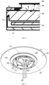
- FIG. 4 is a cross-sectional view of a partial structure of the wafer carrying mechanism according to an embodiment.
- FIG. 5 is a top view of a structure of a support plate 120 of the wafer carrying mechanism according to an embodiment.
- the first distance adjusting piece 500 includes threaded rods 510, nuts 520, and washers 530, wherein there are a plurality of threaded rods 510, and the threaded rods 510 are arranged at intervals along the circumference of the support plate 120; each threaded rod 510 is vertically disposed, and an upper end of the threaded rod 510 is fixedly connected to the cooling structure 400; first unthreaded holes 121 are provided at positions corresponding to the threaded rods 510 on the support plate 120, and the threaded rods 510 penetrate through the first unthreaded holes 121; the washer 530 is provided on each threaded rod 510 in a sleeving mode and the washer 530 is located between the cooling structure 400 and the support plate 120 for adjusting the vertical distance between the cooling structure 400 and the support plate 120 by setting the number and/or thickness of the washer 530.
- the washers 530 of a suitable number and/or thickness may be stacked between the cooling structure 400 and the support plate 120 depending on the desired distance to bring the vertical distance to the desired distance.
- the number and/or thickness of the washers 530 disposed on each threaded rod 510 in the sleeving mode is identical.
- the number of the nuts 520 is the same as the number of the threaded rods 510, and the nuts 520 are located below the support plate 120; the nuts 520 are threadedly matched with the threaded rods 510 in one-to-one correspondence for fixedly connecting the cooling structure 400, the support plate 120, and the washers 530.
- the range of the vertical distance between the cooling structure 400 and the heater 300 can be achieved by changing the number and/or thickness of the washers 530 for ease of adjustment.
- fixing of the cooling structure 400 on the support plate 120 is also achieved by means of the locking action of the nuts 520, preventing displacement and misalignment of the cooling structure 400 during operation of the wafer carrying mechanism, and further ensuring cooling reliability of the cooling structure 400 for the carrying plate 200.
- the first distance adjusting piece 500 of any other structure may be used to adjust the vertical distance between the support plate 120 and the cooling structure 400 in practical applications, and the present application is not particularly limited thereto.
- threaded rods 510 there are a plurality of threaded rods 510, and the threaded rods 510 are arranged at intervals along the circumference of the support plate 120, by such arrangement, on the one hand, stability of the raising or lowering of the cooling structure 400 at various positions along the circumference can be guaranteed, avoiding deflection due to uneven local force on the cooling structure 400, and on the other hand, reliability of the connection of the cooling structure 400 and the support plate 120 can be guaranteed.
- the number of the threaded rods 510 is for example 5, and correspondingly, as shown in FIG. 5 , the number of the first unthreaded holes 121 is 5.
- the threaded rods 510 can also be provided in other numbers, such as four, six, or eight, etc.; the number of the nuts 520 and the number of the first unthreaded holes 121 are both the same as the number of the threaded rods 510.
- the washer 530 is disposed on the threaded rod 510 in a sleeving mode. By such arrangement, it is able to limit the washer 530 using the threaded rod 510, thereby ensuring stable support of the washer 530 to the cooling structure 400.
- the disclosure is not limited thereto, and in practical applications, the washer 530 can be disposed anywhere between the cooling structure 400 and the support plate 120 instead of being disposed on the threaded rod 510 in a sleeving mode.
- the threaded rod 510 is integrated with the cooling structure 400, specifically, the two are joined together by welding.
- the flange plate 110 has a central through hole 110a, and a first connecting portion 111 is provided on a hole wall of the central through hole 110a; a portion of the support plate 120 is located in the central through hole 110a, and a second connecting portion 124 is provided on an outer peripheral wall of the support plate 120; the second connecting portion 124 and the first connecting portion 111 are disposed in a superimposing mode, and the second connecting portion 124 is located under the first connecting portion 111; a plurality of threaded holes are provided on the first connecting portion 111 at intervals along the circumference of the support plate 120, and a plurality of second unthreaded holes 122 are provided on the second connecting portion 124; the number of the second unthreaded holes 122 is the same as the number of the threaded holes and the second unthreaded holes 122 and the threaded holes are provided in one-to-one correspondence; moreover, the second distance adjusting piece 600 includes screws; the number of the second unthreaded holes 122 is the same as the number of
- the screw when it is required to increase the vertical distance between the cooling structure 400 and the heater 300, the screw can be rotated to move the screw in a direction out of the threaded hole (i.e., downwards), at which point the support plate 120 moves downwards and always abuts against the head of the screw, thereby increasing the vertical distance between the cooling structure 400 and the heater 300; when it is required to reduce the vertical distance between the cooling structure 400 and the heater 300, the screw can be rotated to move the screw in a direction, opposite to the aforementioned rotating direction, of entering the screw hole, at which point the support plate 120 will move upwards under the support of the head of the screw to bring the cooling structure 400 near the heater 300, thereby reducing the vertical distance between the cooling structure 400 and the heater 300.
- the second distance adjusting piece 600 is provided in a form that is simple in structure and easy to implement.
- the screws are arranged at intervals along the circumference of the support plate 120.
- the support plate 120 can be smoothly raised or lowered at various positions along the circumference, avoiding deflection of the cooling structure 400 due to the uneven local force on the support plate 120.
- the number of the screws is 6, and correspondingly, as shown in FIG. 5 , the number of second unthreaded holes 122 is 6.
- the screws can also be provided in other numbers, such as four, six or eight, etc.; the number of the threaded holes and the number of the second unthreaded holes 122 are both the same as the number of the threaded rods 510.
- the vertical distance between the cooling structure 400 and the heater 300 is greater than or equal to 0.5 mm and less than or equal to 4 mm, that is, the distance adjusting assembly adjusts the distance between the cooling structure 400 and the heater 300 in the range of 0.5 mm to 4 mm.
- the requirements of different high-temperature processes can be met, and the overall thickness of the wafer carrying mechanism can also be reduced, thereby facilitating a compact design of the wafer carrying mechanism of the present embodiment.
- FIG. 6 is an enlarged view of a partial structure of the structure shown in FIG. 1 .
- a connecting wall 112 extending in the direction of the heater 300 is provided on the flange plate 110 and at an edge of the flange plate 110, and the connecting wall 112 is fixedly connected, for example by welding, to the heater 300.
- the aforementioned accommodating space is formed between an inner peripheral surface of the connecting wall 112, a lower surface of the heater 300 and an upper surface of the flange plate 110.
- the connecting wall 112 is welded with the heater body 310 of the heater 300, that is, a side wall of the accommodating space is formed by the connecting wall 112.
- a temperature difference is generated between the heater body 310 and the flange plate 110, and an internal stress is generated by the difference in the amount of expansion ; and by providing the connecting wall 112 extending in the direction of the heater 300 at the outer periphery of the flange plate 110 and fixedly connecting the connecting wall 112 to the heater body 310, the connecting wall 112 is relatively thin, which can deform in a high-temperature state to relieve the internal stress caused by the temperature difference. Moreover, reliable connection between the flange plate 110 and the heater body 310 derives from the manner that the connecting wall 112 is fixedly connected to the heater body 310.
- the thickness of the connecting wall 112 is 1 mm or less.
- the cooling structure 400 includes a cooling screen 410, and a cooling plate 420 connected to a bottom of the cooling screen 410, specifically, the cooling plate 420 is provided with a flow channel, the flow channel is used for delivering a cooling liquid, and a radial dimension of the cooling screen 410 is greater than or equal to a radial dimension of the carrying plate 200.
- the range within the maximum outer diameter of the cooling screen 410 is an optimal cooling range, and the cooling screen 410 has high cooling efficiency within its maximum outer diameter and low cooling efficiency beyond the maximum outer diameter; by setting the radial dimension of the cooling screen 410 greater than or equal to the radial dimension of the carrying plate 200, the cooling structure 400 is able to achieve overall cooling of the carrying plate 200, which not only has high cooling efficiency but also has good cooling uniformity.
- the greater the radiant area A the greater the heat flow rate Q, and the greater the radiant heat transfer efficiency, and thus, increasing the cooling area of the cooling screen 410 may effectively increase the radiant heat transfer amount to achieve efficient cooling of the carrying plate 200.
- FIG. 7 is a partial structural view of the wafer carrying mechanism according to an embodiment.
- the cooling structure 400 may further include cooling liquid tubes 430, and the cooling liquid tubes 430 are in communication with the flow channel provided in the cooling plate 420 for inputting a cooling liquid into the flow channel.
- process holes 411 may also be provided on the cooling structure 400 to meet corresponding process needs.
- a middle portion of the support plate 120 may also be provided with a routing hole 123, and the routing hole 123 enables passing of the cooling liquid tubes 430 and other cables of the wafer carrying mechanism, ensuring structural compactness and neat appearance of the wafer carrying mechanism.
- the present embodiments also provide a semiconductor process apparatus, the semiconductor process apparatus includes a process chamber and the aforementioned wafer carrying mechanism, specifically, the wafer carrying mechanism is disposed within the process chamber.
- the semiconductor process apparatus accordingly has all the advantages of the aforementioned wafer carrying mechanism, which are not described in any further detail herein.
Landscapes
- Chemical & Material Sciences (AREA)
- Engineering & Computer Science (AREA)
- Chemical Kinetics & Catalysis (AREA)
- Materials Engineering (AREA)
- Mechanical Engineering (AREA)
- Metallurgy (AREA)
- Organic Chemistry (AREA)
- Physics & Mathematics (AREA)
- Plasma & Fusion (AREA)
- Analytical Chemistry (AREA)
- Container, Conveyance, Adherence, Positioning, Of Wafer (AREA)
- Crystals, And After-Treatments Of Crystals (AREA)
Abstract
Description
- The present application relates to the field of semiconductor process apparatuses, and in particular, to a wafer carrying mechanism and a semiconductor process apparatus.
- During the high temperature physical vapor deposition process, a carrying plate needs to be used to heat a wafer to a certain process temperature, and the carrying plate needs to have the capability to regulate the wafer temperature in a high temperature state, that is, the carrying plate not only can heat the wafer, but also can cool the wafer when needed. The cooling capacity requirements on the carrying plate differ for different processes (especially the high-temperature process), for example, there are processes that only require the carrying plate to heat the wafer, and there are processes that require the carrying plate to have a strong cooling capacity. In general, it is difficult to meet the needs of different processes using the same carrying plate.
- A first objective of the present application is to provide a wafer carrying mechanism to solve the technical problem that existing wafer carrying mechanisms have difficulty in meeting the needs of various high-temperature processes.
- A wafer carrying mechanism provided by the present application is used for a semiconductor process apparatus, the wafer carrying mechanism is disposed in a process chamber of the semiconductor process apparatus, the wafer carrying mechanism includes a mounting support, a carrying plate, a heater, a cooling structure, and a distance adjusting assembly, wherein the carrying plate is disposed on the heater for carrying a wafer; the heater is disposed on the mounting support, and an accommodating space is formed between the heater and the mounting support; the cooling structure is located in the accommodating space for cooling the heater; and the distance adjusting assembly is separately connected to the mounting support and the cooling structure for adjusting a vertical distance between the cooling structure and the heater.
- Further, the mounting support includes a flange plate, and a support plate, wherein the flange plate is connected to the heater, and the accommodating space is formed between the flange plate and the heater; the support plate is connected to the flange plate, and at least a portion of the support plate is located in the accommodating space and connected to the cooling structure for supporting the cooling structure; and
the distance adjusting assembly includes a first distance adjusting piece and/or a second distance adjusting piece, the cooling structure is connected to the support plate by the first distance adjusting piece, and the first distance adjusting piece is used for adjusting a vertical distance between the cooling structure and the support plate; and/or the support plate is connected to the flange plate by the second distance adjusting piece, and the second distance adjusting piece is used for adjusting a vertical distance between the support plate and the heater. - Further, the first distance adjusting piece includes threaded rods, nuts, and washers, wherein there are a plurality of threaded rods, and the threaded rods are arranged at intervals along the circumference of the support plate; each threaded rod is vertically disposed, and an upper end of the threaded rod is fixedly connected to the cooling structure; first unthreaded holes are provided at positions corresponding to the threaded rods on the support plate, and the threaded rods penetrate through the first unthreaded holes;
- the washers are located between the cooling structure and the support plate for adjusting the vertical distance between the cooling structure and the support plate by setting the number and/or thickness of the washers; and
- the number of the nuts is the same as the number of the threaded rods, and the nuts are located below the support plate; the nuts are threadedly matched with the threaded rods in one-to-one correspondence for fixedly connecting the cooling structure, the support plate, and the washers.
- Further, the flange plate is provided with a central through hole, and a first connecting portion is provided on a hole wall of the central through hole; a portion of the support plate is located in the central through hole; a second connecting portion is provided on an outer peripheral wall of the support plate; the second connecting portion and the first connecting portion are disposed in a superimposing mode, and the second connecting portion is located under the first connecting portion;
- a plurality of threaded holes are provided on the first connecting portion at intervals along the circumference of the support plate, and a plurality of second unthreaded holes are provided on the second connecting portion; the number of the second unthreaded holes is the same as the number of the threaded holes, and the second unthreaded holes and the threaded holes are provided in one-to-one correspondence; and
- the second distance adjusting piece includes a plurality of screws, the number of the screws is the same as the number of the threaded holes, and the screws pass through the second unthreaded holes in one-to-one correspondence and are threadedly connected to the corresponding threaded holes; the vertical distance between the support plate and the heater is adjusted by adjusting relative positions of the screws and the threaded holes in an axial direction of the threaded holes.
- Further, a connecting wall extending in the direction of the heater is provided on the flange plate and at an edge of the flange plate, the connecting wall is fixedly connected to the heater, and the accommodating space is formed between an inner peripheral surface of the connecting wall, a lower surface of the heater and an upper surface of the flange plate.
- Further, the wafer carrying mechanism further includes a pressing ring, and the pressing ring includes an annular body fixedly connected to the heater and surrounding the carrying plate, and pressing teeth disposed in the annular body and protruding relative to an inner peripheral surface of the annular body, wherein there are a plurality of pressing teeth, and the pressing teeth are arranged at intervals along the circumference of the annular body, at least a portion of each of the pressing teeth being elastically superimposed on the carrying plate for pressing the carrying plate against the heater.
- Further, the vertical distance between the cooling structure and the heater is greater than or equal to 0.5 mm and less than or equal to 4 mm.
- Further, the cooling structure includes a cooling screen, and a cooling plate connected to a bottom of the cooling screen, wherein the cooling plate is provided with a flow channel, the flow channel is used for delivering a cooling liquid, and a radial dimension of the cooling screen is greater than or equal to a radial dimension of the carrying plate.
- Further, the heater includes a heater body, and a heating wire embedded in the heater body.
- The benefits of the wafer carrying mechanism provided by the present application are as follows:
according to the wafer carrying mechanism, the vertical distance between the cooling structure and the heater is adjusted by means of the distance adjusting assembly separately connected to the mounting support and the cooling structure. Not only can the heat conduction efficiency of gas be adjusted to enable adjustment of the cooling capacity, thereby meeting the needs of different high-temperature processes, but also the cooling structure and the heater are made in a non-direct contact state, in this way, during use of the wafer carrying mechanism, the risk of shattering of the carrying plate by the heater due to sudden cooling of the cooling structure can be avoided, thus ensuring that the carrying plate can always be cooled at high temperature, and making the wafer carrying mechanism more advantageous in high-temperature processes. - A second objective of the present application is to provide a semiconductor process apparatus to solve the technical problem that existing semiconductor process apparatuses have difficulty in meeting the needs of different high-temperature processes.
- The semiconductor process apparatus provided by the present application includes a process chamber and the aforementioned wafer carrying mechanism, the wafer carrying mechanism being disposed within the process chamber.
- The benefits brought about by the semiconductor process apparatus provided by the present application are as follows:
by providing the aforementioned wafer carrying mechanism provided by the present application within the process chamber of the semiconductor process apparatus, the semiconductor process apparatus accordingly has all the advantages of the aforementioned wafer carrying mechanism, which are not described in any further detail herein. - To describe the technical solutions in the embodiments of the present application or in the prior art more clearly, the following briefly introduces the drawings required for describing the embodiments or the prior art. Apparently, the drawings in the following description are merely embodiments of the present application, and those of ordinary skill in the art may still derive other drawings from these drawings without creative efforts.
-
FIG. 1 is a cross-sectional view of a structure of a wafer carrying mechanism according to an embodiment of the present application when a wafer is carried; -
FIG. 2 is a top view of a structure of the connection between a pressing ring and a carrying plate of the wafer carrying mechanism according to an embodiment of the present application; -
FIG. 3 is an enlarged view of a partial structure of the connection between the pressing ring and the carrying plate of the wafer carrying mechanism according to an embodiment of the present application; -
FIG. 4 is a cross-sectional view of a partial structure of the wafer carrying mechanism according to an embodiment of the present disclosure; -
FIG. 5 is a top view of a structure of a support plate of the wafer carrying mechanism according to an embodiment of the present disclosure; -
FIG. 6 is an enlarged view of a partial structure of the structure shown inFIG. 1 ; and -
FIG. 7 is a partial structural view of the wafer carrying mechanism according to an embodiment of the present disclosure. -
- 100-mounting support; 200-carrying plate; 300-heater; 400-cooling structure; 500-first distance adjusting piece; 600-second distance adjusting piece; 700-pressing ring; 800-fastening screw; 900-wafer;
- 110-flange plate; 110a-central through hole; 111-first connecting portion; 112-connecting wall; 120-support plate; 121-first unthreaded hole; 122-second unthreaded hole; 123-routing hole; 124-second connecting portion;
- 310-heater body; 320-heating wire;
- 410-cooling screen; 411-process hole; 420-cooling plate; 430-cooling liquid tube;
- 510-threaded rod; 520-nut; 530-washer;
- 710-annular body; 720-pressing tooth.
- In order that the above objectives, features, and advantages of the present application will become more apparent, the following detailed description of specific embodiments of the present disclosure will be made in conjunction with the accompanying drawings. It should be understood that the specific embodiments described herein are intended only to explain the present application and are not intended to limit it.
-
FIG. 1 is a cross-sectional view of a structure of a wafer carrying mechanism according to an embodiment when a wafer is carried. As shown inFIG. 1 , the present embodiment provides a wafer carrying mechanism used for a semiconductor process apparatus, specifically, the wafer carrying mechanism is disposed in a process chamber of the semiconductor process apparatus, the wafer carrying mechanism includes amounting support 100, acarrying plate 200, aheater 300, acooling structure 400, and a distance adjusting assembly, wherein thecarrying plate 200 is disposed on theheater 300 for carrying awafer 900, optionally, a lower surface of thecarrying plate 200 is attached to an upper surface of theheater 300 to improve heat conduction efficiency of theheater 300. Themounting support 100 is fixedly disposed in the process chamber, theheater 300 is disposed on themounting support 100, and an accommodating space is formed between theheater 300 and themounting support 100; thecooling structure 400 is located within the accommodating space for cooling theheater 300. - During use of the wafer carrying mechanism, the heat generated by heating of the
heater 300 can be transferred directly to thecarrying plate 200 to provide the desired temperature of thewafer 900 under a current high-temperature process; thecooling structure 400 acts as a heat sink for thecarrying plate 200, however, theheater 300 is what thecooling structure 400 directly affects, that is, thecarrying plate 200 is indirectly cooled by cooling theheater 300. By changing the heating power of theheater 300, a balance between the heating power of theheater 300 and the cooling power of thecooling structure 400 may be achieved, thereby enabling thewafer 900 disposed on thecarrying plate 200 to be always maintained at a desired process temperature. - When it is required to cool the
carrying plate 200, only the heating power of theheater 300 needs to be reduced, theheater 300 is cooled by thecooling structure 400 such that the temperature of theheater 300 is reduced until the temperature of theheater 300 is lower than the temperature of thecarrying plate 200, at which point heat will be transferred from thecarrying plate 200 to theheater 300, and the heat of theheater 300 is further transferred to thecooling structure 400, achieving indirect cooling of thecarrying plate 200 by thecooling structure 400. - The distance adjusting assembly is separately connected to the
mounting support 100 and thecooling structure 400 for adjusting a vertical distance between thecooling structure 400 and theheater 300. By adjusting the vertical distance between thecooling structure 400 and theheater 300 by means of the aforementioned distance adjusting assembly, the heat conduction efficiency of gas can be adjusted to enable adjustment of the cooling capacity, thereby meeting the needs of different high-temperature processes. - Furthermore, by adjusting the vertical distance between the
cooling structure 400 and theheater 300 by means of the aforementioned distance adjusting assembly, thecooling structure 400 and theheater 300 may also be in a non-direct contact state, in this way, during use of the wafer carrying mechanism, the risk of shattering of thecarrying plate 200 by theheater 300 due to sudden cooling of thecooling structure 400 can be avoided, thus ensuring that thecarrying plate 200 can always be cooled at high temperature, and making the wafer carrying mechanism more advantageous in high-temperature processes. - From the formula for heat conduction

heater 300, T2 is the temperature of thecooling structure 400, and Δx is the vertical distance between theheater 300 and thecooling structure 400, it can be seen that the smaller the vertical distance, the larger the heat flow rate Q of heat conduction; conversely, the larger the vertical distance, the smaller the heat flow rate Q of heat conduction, based on this, adjustment of the heat flow rate Q of heat conduction can be achieved by adjusting the aforementioned vertical distance, thereby achieving different heat conduction effects. - In some optional embodiments, the
carrying plate 200 is an electrostatic chuck. The electrostatic chuck has relatively high wafer utilization, few particles, and uniform edge etching and deposition rates. Using the electrostatic chuck to carry thewafer 900 can avoid movement or misalignment of thewafer 900 during processing, and the electrostatic chuck can be electrically connected to a radio frequency power supply to provide radio frequency bias to thewafer 900, and the surface temperature of thewafer 900 can also be controlled by using theaforementioned heater 300 andcooling structure 400. Specifically, thecarrying plate 200 may be fabricated from a dielectric material such as Al2O3 ceramic, AlN ceramic, and the like, which contains therein a DC electrode electrically connected to a DC power supply, and an electrostatic adsorption force is generated to adsorb thewafer 900 by applying a DC voltage to the DC electrode. - With continued reference to
FIG. 1 , in some optional embodiments, theheater 300 may include aheater body 310, and a heating wire 320 embedded in theheater body 310, wherein the heating wire 320 is in electrical connection with a power supply. During operation of the wafer carrying mechanism, the power supply energizes the heating wire 320, the heating wire 320 generates and transfers heat to theheater body 310, causing the temperature of theheater body 310 to rise, and theheater body 310 with rising temperature transfers heat to thecarrying plate 200, thereby achieving heating of thecarrying plate 200. -
FIG. 2 is a top view of a structure of the connection between apressing ring 700 and a carryingplate 200 of the wafer carrying mechanism according to an embodiment.FIG. 3 is an enlarged view of a partial structure of the connection between thepressing ring 700 and the carryingplate 200 of the wafer carrying mechanism according to an embodiment. With continued reference toFIG. 1 , in conjunction withFIGS. 2 and3 , in some optional embodiments, the wafer carrying mechanism further includes apressing ring 700, and the carryingplate 200 is disposed on theheater 300 by thepressing ring 700. Specifically, thepressing ring 700 includes anannular body 710 fixedly connected to theheater 300 and surrounding the carryingplate 200, andpressing teeth 720 disposed in theannular body 710 and protruding relative to an inner peripheral surface of theannular body 710, wherein there are a plurality ofpressing teeth 720, and thepressing teeth 720 are arranged at intervals along the circumference of theannular body 710, at least a portion of each of thepressing teeth 720 being elastically superimposed on the carryingplate 200 for pressing the carryingplate 200 against theheater 300. - Providing of the
pressing ring 700 enables the fixing of the carryingplate 200 on theheater 300. Moreover, during operation of the wafer carrying mechanism, a difference in the amount of expansion exists between the carryingplate 200 and theheater 300 due to different coefficients of thermal expansion. As theheater body 310 has a greater coefficient of thermal expansion and a greater amount of expansion relative to the carryingplate 200, the radial distance A between thepressing ring 700 and the carryingplate 200 may increase, to this end, by elastically superimposing at least a portion of eachpressing tooth 720 on the carryingplate 200, elastic deformation of thepressing tooth 720 can be utilized to adapt to the increased radial distance A. For example, as shown inFIG. 3 , due to existence of an inclination angle B of thepressing tooth 720 with respect to a horizontal plane, the inclination angle B causes thepressing tooth 720 to always apply elastic pressure to the carryingplate 200, in this case, thepressing tooth 720 is able to always press the carryingplate 200 even if the radial distance A increases, thus avoiding misalignment of the carryingplate 200. - In some optional embodiments, the thickness of the
pressing teeth 720 is 0.5 mm. By such arrangement, on the one hand, it is able to guarantee that thepressing teeth 720 apply a sufficient pressing force to the carryingplate 200 and guarantee the reliability of fixing of the carryingplate 200, and on the other hand, it is also able to avoid damage to the carryingplate 200 due to excessive pressing force. - With continued reference to
FIG. 2 , in some optional embodiments, theannular body 710 of thepressing ring 700 is fixedly connected to theheater body 310 of theheater 300 by a plurality of fastening screws 800. When it is required to maintain thepressing ring 700, by such arrangement, thepressing ring 700 can be directly removed from theheater 300, and thepressing ring 700 can be installed back after the maintenance is completed, which is convenient and efficient. - With continued reference to
FIG. 1 , in some optional embodiments, the mountingsupport 100 includes aflange plate 110, and asupport plate 120, wherein theflange plate 110 is connected to theheater 300, and the aforementioned accommodating space is formed between theflange plate 110 and theheater 300; thesupport plate 120 is connected to theflange plate 110, and at least a portion of thesupport plate 120 is located in the aforementioned accommodating space and connected to thecooling structure 400 for supporting thecooling structure 400. The distance adjusting assembly includes a firstdistance adjusting piece 500 and/or a seconddistance adjusting piece 600, thecooling structure 400 is connected to thesupport plate 120 by the firstdistance adjusting piece 500, and the firstdistance adjusting piece 500 is used for adjusting a vertical distance between the coolingstructure 400 and thesupport plate 120; and/or, thesupport plate 120 is connected to theflange plate 110 by the seconddistance adjusting piece 600, and the seconddistance adjusting piece 600 is used for adjusting a vertical distance between thesupport plate 120 and theheater 300. - In the wafer carrying mechanism, when the distance adjusting assembly includes only the first
distance adjusting piece 500, the firstdistance adjusting piece 500 can be utilized to adjust the vertical distance between the coolingstructure 400 and thesupport plate 120 for the purpose of adjusting the vertical distance between the coolingstructure 400 and theheater 300; when the distance adjusting assembly includes only the seconddistance adjusting piece 600, the seconddistance adjusting piece 600 can be utilized to adjust the vertical distance between thesupport plate 120 and theheater 300. As a change in the position of thesupport plate 120 causes a consequent change in the position of thecooling structure 400 connected to thesupport plate 120, the purpose of adjusting the vertical distance between the coolingstructure 400 and theheater 300 is indirectly achieved; when the distance adjusting assembly includes both the firstdistance adjusting piece 500 and the seconddistance adjusting piece 600, either the firstdistance adjusting piece 500 or the seconddistance adjusting piece 600 or both of the firstdistance adjusting piece 500 and the seconddistance adjusting piece 600 can be utilized for the purpose of adjusting the vertical distance between the coolingstructure 400 and theheater 300. - The wafer carrying mechanism may enable adjustment of the vertical distance between the cooling
structure 400 and theheater 300 by selectively using the firstdistance adjusting piece 500 and/or the seconddistance adjusting piece 600, moreover, connection to components in the process chamber can also be achieved by means of theflange plate 110, thereby achieving fixing of the wafer carrying mechanism of the present embodiment in the process chamber. -
FIG. 4 is a cross-sectional view of a partial structure of the wafer carrying mechanism according to an embodiment.FIG. 5 is a top view of a structure of asupport plate 120 of the wafer carrying mechanism according to an embodiment. With continued reference toFIG. 1 , in conjunction withFIGS. 4 and5 , in some optional embodiments, the firstdistance adjusting piece 500 includes threadedrods 510,nuts 520, andwashers 530, wherein there are a plurality of threadedrods 510, and the threadedrods 510 are arranged at intervals along the circumference of thesupport plate 120; each threadedrod 510 is vertically disposed, and an upper end of the threadedrod 510 is fixedly connected to thecooling structure 400; first unthreadedholes 121 are provided at positions corresponding to the threadedrods 510 on thesupport plate 120, and the threadedrods 510 penetrate through the firstunthreaded holes 121; thewasher 530 is provided on each threadedrod 510 in a sleeving mode and thewasher 530 is located between the coolingstructure 400 and thesupport plate 120 for adjusting the vertical distance between the coolingstructure 400 and thesupport plate 120 by setting the number and/or thickness of thewasher 530. When the vertical distance between the coolingstructure 400 and theheater 300 needs to be adjusted using the firstdistance adjusting piece 500, thewashers 530 of a suitable number and/or thickness may be stacked between the coolingstructure 400 and thesupport plate 120 depending on the desired distance to bring the vertical distance to the desired distance. Optionally, to ensure levelness of thecooling structure 400, the number and/or thickness of thewashers 530 disposed on each threadedrod 510 in the sleeving mode is identical. - The number of the
nuts 520 is the same as the number of the threadedrods 510, and thenuts 520 are located below thesupport plate 120; thenuts 520 are threadedly matched with the threadedrods 510 in one-to-one correspondence for fixedly connecting thecooling structure 400, thesupport plate 120, and thewashers 530. - According to the structural form of the aforementioned first
distance adjusting piece 500, the range of the vertical distance between the coolingstructure 400 and theheater 300 can be achieved by changing the number and/or thickness of thewashers 530 for ease of adjustment. Moreover, fixing of thecooling structure 400 on thesupport plate 120 is also achieved by means of the locking action of thenuts 520, preventing displacement and misalignment of thecooling structure 400 during operation of the wafer carrying mechanism, and further ensuring cooling reliability of thecooling structure 400 for the carryingplate 200. Of course, the firstdistance adjusting piece 500 of any other structure may be used to adjust the vertical distance between thesupport plate 120 and thecooling structure 400 in practical applications, and the present application is not particularly limited thereto. - Furthermore, there are a plurality of threaded
rods 510, and the threadedrods 510 are arranged at intervals along the circumference of thesupport plate 120, by such arrangement, on the one hand, stability of the raising or lowering of thecooling structure 400 at various positions along the circumference can be guaranteed, avoiding deflection due to uneven local force on thecooling structure 400, and on the other hand, reliability of the connection of thecooling structure 400 and thesupport plate 120 can be guaranteed. The number of the threadedrods 510 is for example 5, and correspondingly, as shown inFIG. 5 , the number of the firstunthreaded holes 121 is 5. It will be appreciated that in other embodiments, the threadedrods 510 can also be provided in other numbers, such as four, six, or eight, etc.; the number of thenuts 520 and the number of the firstunthreaded holes 121 are both the same as the number of the threadedrods 510. - It is to be noted that in the present embodiment, the
washer 530 is disposed on the threadedrod 510 in a sleeving mode. By such arrangement, it is able to limit thewasher 530 using the threadedrod 510, thereby ensuring stable support of thewasher 530 to thecooling structure 400. However, the disclosure is not limited thereto, and in practical applications, thewasher 530 can be disposed anywhere between the coolingstructure 400 and thesupport plate 120 instead of being disposed on the threadedrod 510 in a sleeving mode. - With continued reference to
FIG. 4 , in some optional embodiments, the threadedrod 510 is integrated with thecooling structure 400, specifically, the two are joined together by welding. - With continued reference to
FIGS. 1 and5 , in some optional embodiments, theflange plate 110 has a central throughhole 110a, and a first connectingportion 111 is provided on a hole wall of the central throughhole 110a; a portion of thesupport plate 120 is located in the central throughhole 110a, and a second connectingportion 124 is provided on an outer peripheral wall of thesupport plate 120; the second connectingportion 124 and the first connectingportion 111 are disposed in a superimposing mode, and the second connectingportion 124 is located under the first connectingportion 111; a plurality of threaded holes are provided on the first connectingportion 111 at intervals along the circumference of thesupport plate 120, and a plurality of secondunthreaded holes 122 are provided on the second connectingportion 124; the number of the second unthreaded holes 122 is the same as the number of the threaded holes and the secondunthreaded holes 122 and the threaded holes are provided in one-to-one correspondence; moreover, the seconddistance adjusting piece 600 includes screws; the number of the screws is the same as the number of the aforementioned threaded holes; and the screws pass through the secondunthreaded holes 122 in one-to-one correspondence and are threadedly connected to the corresponding threaded holes. - When the vertical distance between the cooling
structure 400 and theheater 300 needs to be adjusted using the seconddistance adjusting piece 600, specifically, as shown inFIG. 1 , when it is required to increase the vertical distance between the coolingstructure 400 and theheater 300, the screw can be rotated to move the screw in a direction out of the threaded hole (i.e., downwards), at which point thesupport plate 120 moves downwards and always abuts against the head of the screw, thereby increasing the vertical distance between the coolingstructure 400 and theheater 300; when it is required to reduce the vertical distance between the coolingstructure 400 and theheater 300, the screw can be rotated to move the screw in a direction, opposite to the aforementioned rotating direction, of entering the screw hole, at which point thesupport plate 120 will move upwards under the support of the head of the screw to bring thecooling structure 400 near theheater 300, thereby reducing the vertical distance between the coolingstructure 400 and theheater 300. - The second
distance adjusting piece 600 is provided in a form that is simple in structure and easy to implement. - In some optional embodiments, there are a plurality of screws in the second
distance adjusting piece 600, and the screws are arranged at intervals along the circumference of thesupport plate 120. By such arrangement, thesupport plate 120 can be smoothly raised or lowered at various positions along the circumference, avoiding deflection of thecooling structure 400 due to the uneven local force on thesupport plate 120. For example, the number of the screws is 6, and correspondingly, as shown inFIG. 5 , the number of secondunthreaded holes 122 is 6. It will be appreciated that in other embodiments, the screws can also be provided in other numbers, such as four, six or eight, etc.; the number of the threaded holes and the number of the secondunthreaded holes 122 are both the same as the number of the threadedrods 510. - Preferably, in the present embodiment, the vertical distance between the cooling
structure 400 and theheater 300 is greater than or equal to 0.5 mm and less than or equal to 4 mm, that is, the distance adjusting assembly adjusts the distance between the coolingstructure 400 and theheater 300 in the range of 0.5 mm to 4 mm. By such arrangement, the requirements of different high-temperature processes can be met, and the overall thickness of the wafer carrying mechanism can also be reduced, thereby facilitating a compact design of the wafer carrying mechanism of the present embodiment. -
FIG. 6 is an enlarged view of a partial structure of the structure shown inFIG. 1 . With continued reference toFIG. 1 , in conjunction withFIG. 6 , in some optional embodiments, a connectingwall 112 extending in the direction of theheater 300 is provided on theflange plate 110 and at an edge of theflange plate 110, and the connectingwall 112 is fixedly connected, for example by welding, to theheater 300. The aforementioned accommodating space is formed between an inner peripheral surface of the connectingwall 112, a lower surface of theheater 300 and an upper surface of theflange plate 110. For example, the connectingwall 112 is welded with theheater body 310 of theheater 300, that is, a side wall of the accommodating space is formed by the connectingwall 112. - In a high-temperature state, a temperature difference is generated between the
heater body 310 and theflange plate 110, and an internal stress is generated by the difference in the amount of expansion ; and by providing the connectingwall 112 extending in the direction of theheater 300 at the outer periphery of theflange plate 110 and fixedly connecting the connectingwall 112 to theheater body 310, the connectingwall 112 is relatively thin, which can deform in a high-temperature state to relieve the internal stress caused by the temperature difference. Moreover, reliable connection between theflange plate 110 and theheater body 310 derives from the manner that the connectingwall 112 is fixedly connected to theheater body 310. - Specifically, in some optional embodiments, the thickness of the connecting
wall 112 is 1 mm or less. - With continued reference to
FIG. 4 , in some optional embodiments, thecooling structure 400 includes acooling screen 410, and acooling plate 420 connected to a bottom of thecooling screen 410, specifically, thecooling plate 420 is provided with a flow channel, the flow channel is used for delivering a cooling liquid, and a radial dimension of thecooling screen 410 is greater than or equal to a radial dimension of the carryingplate 200. - In the wafer carrying mechanism, the range within the maximum outer diameter of the
cooling screen 410 is an optimal cooling range, and thecooling screen 410 has high cooling efficiency within its maximum outer diameter and low cooling efficiency beyond the maximum outer diameter; by setting the radial dimension of thecooling screen 410 greater than or equal to the radial dimension of the carryingplate 200, thecooling structure 400 is able to achieve overall cooling of the carryingplate 200, which not only has high cooling efficiency but also has good cooling uniformity. - Specifically, the wafer carrying mechanism has a radiant heat flow rate Q, and the heat flow rate Q is calculated by the formula: Q=5.67×10⁻⁸ εA(T14-T24), where the energy flux density radiated from the surface of an absolute blackbody at a temperature of 100K is 5.67 W/m2, ε is the average emissivity, A is the radiant area, T1 is the temperature of the
heater 300, and T2 is the temperature of thecooling structure 400. As can be seen, the greater the radiant area A, the greater the heat flow rate Q, and the greater the radiant heat transfer efficiency, and thus, increasing the cooling area of thecooling screen 410 may effectively increase the radiant heat transfer amount to achieve efficient cooling of the carryingplate 200. -
FIG. 7 is a partial structural view of the wafer carrying mechanism according to an embodiment. With continued reference toFIG. 4 , in conjunction withFIG. 7 , in some optional embodiments, thecooling structure 400 may further include coolingliquid tubes 430, and the coolingliquid tubes 430 are in communication with the flow channel provided in thecooling plate 420 for inputting a cooling liquid into the flow channel. - With continued reference to
FIG. 7 , in some optional embodiments, process holes 411 may also be provided on thecooling structure 400 to meet corresponding process needs. In addition, a middle portion of thesupport plate 120 may also be provided with arouting hole 123, and therouting hole 123 enables passing of the coolingliquid tubes 430 and other cables of the wafer carrying mechanism, ensuring structural compactness and neat appearance of the wafer carrying mechanism. - In addition, the present embodiments also provide a semiconductor process apparatus, the semiconductor process apparatus includes a process chamber and the aforementioned wafer carrying mechanism, specifically, the wafer carrying mechanism is disposed within the process chamber.
- By providing the aforementioned wafer carrying mechanism within the process chamber of the semiconductor process apparatus, the semiconductor process apparatus accordingly has all the advantages of the aforementioned wafer carrying mechanism, which are not described in any further detail herein.
- Although the present application is disclosed above, the present application is not limited thereto. Various changes and modifications may be made by anyone skilled in the art without departing from the spirit and scope of the present application, and the scope of the present application shall accordingly be defined by the claims.
- Finally, it should also be noted that relational terms such as first and second and the like are used herein solely to distinguish one entity or operation from another entity or operation without necessarily requiring or implying any actual relationship or order between such entities or operations. Furthermore, the terms "includes" or any other variation thereof, are intended to cover a non-exclusive inclusion, such that a process, method, article, or apparatus that includes a list of elements not only includes those elements but also includes other elements not expressly listed or inherent to such process, method, article, or apparatus. In the absence of further limitations, an element defined by the phrase "includes an ..." does not preclude the existence of another identical element in the process, method, article or apparatus including the element.
- Descriptions of orientations such as "upper", "lower", and the like in the aforementioned embodiments are based on what is shown in the drawings.
- The aforementioned description of the disclosed embodiments enables any person skilled in the art to make or use the present application. Various modifications to these embodiments will be readily apparent to those skilled in the art, and the generic principles defined herein may be implemented in other embodiments without departing from the spirit or scope of the present application. Thus, the present application is not intended to be limited to the embodiments shown herein but is to accord with the widest scope consistent with the principles and novel features disclosed herein.
Claims (10)
- A wafer carrying mechanism, used for a semiconductor process apparatus, the wafer carrying mechanism being disposed in a process chamber of the semiconductor process apparatus, the wafer carrying mechanism comprising a mounting support, a carrying plate, a heater, a cooling structure, and a distance adjusting assembly, wherein the carrying plate is disposed on the heater for carrying a wafer; the heater is disposed on the mounting support, and an accommodating space is formed between the heater and the mounting support; the cooling structure is located in the accommodating space for cooling the heater; and the distance adjusting assembly is separately connected to the mounting support and the cooling structure for adjusting a vertical distance between the cooling structure and the heater.
- The wafer carrying mechanism according to claim 1, wherein the mounting support comprises a flange plate, and a support plate; the flange plate is connected to the heater, and the accommodating space is formed between the flange plate and the heater; the support plate is connected to the flange plate, and at least a portion of the support plate is located in the accommodating space and connected to the cooling structure for supporting the cooling structure; and
the distance adjusting assembly comprises a first distance adjusting piece and/or a second distance adjusting piece; the cooling structure is connected to the support plate by the first distance adjusting piece, and the first distance adjusting piece is used for adjusting a vertical distance between the cooling structure and the support plate; and/or the support plate is connected to the flange plate by the second distance adjusting piece, and the second distance adjusting piece is used for adjusting a vertical distance between the support plate and the heater. - The wafer carrying mechanism according to claim 2, wherein the first distance adjusting piece comprises threaded rods, nuts, and washers, there are a plurality of threaded rods, and the threaded rods are arranged at intervals along the circumference of the support plate; each threaded rod is vertically disposed, and an upper end of the threaded rod is fixedly connected to the cooling structure; first unthreaded holes are provided at positions corresponding to the threaded rods on the support plate, and the threaded rods penetrate through the first unthreaded holes;the washers are located between the cooling structure and the support plate for adjusting the vertical distance between the cooling structure and the support plate by setting the number and/or thickness of the washers; andthe number of the nuts is the same as the number of the threaded rods, and the nuts are located below the support plate; the nuts are threadedly matched with the threaded rods in one-to-one correspondence for fixedly connecting the cooling structure, the support plate, and the washers.
- The wafer carrying mechanism according to claim 2, wherein the flange plate is provided with a central through hole, and a first connecting portion is provided on a hole wall of the central through hole; a portion of the support plate is located in the central through hole; a second connecting portion is provided on an outer peripheral wall of the support plate; the second connecting portion and the first connecting portion are disposed in a superimposing mode, and the second connecting portion is located under the first connecting portion;a plurality of threaded holes are provided on the first connecting portion at intervals along the circumference of the support plate, and a plurality of second unthreaded holes are provided on the second connecting portion; the number of the second unthreaded holes is the same as the number of the threaded holes, and the second unthreaded holes and the threaded holes are provided in one-to-one correspondence; andthe second distance adjusting piece comprises a plurality of screws, the number of the screws is the same as the number of the threaded holes, and the screws pass through the second unthreaded holes in one-to-one correspondence and are threadedly connected to the corresponding threaded holes; the vertical distance between the support plate and the heater is adjusted by adjusting relative positions of the screws and the threaded holes in an axial direction of the threaded holes.
- The wafer carrying mechanism according to claim 2, wherein a connecting wall extending in a direction of the heater is provided on the flange plate and at an edge of the flange plate, the connecting wall is fixedly connected to the heater, and the accommodating space is formed between an inner peripheral surface of the connecting wall, a lower surface of the heater and an upper surface of the flange plate.
- The wafer carrying mechanism according to any one of claims 1-5, wherein the wafer carrying mechanism further comprises a pressing ring, the pressing ring comprises an annular body fixedly connected to the heater and surrounding the carrying plate, and pressing teeth disposed in the annular body and protruding relative to an inner peripheral surface of the annular body; there are a plurality of pressing teeth, and the pressing teeth are arranged at intervals along the circumference of the annular body, at least a portion of each of the pressing teeth being elastically superimposed on the carrying plate for pressing the carrying plate against the heater.
- The wafer carrying mechanism according to any one of claims 1-5, wherein the vertical distance between the cooling structure and the heater is greater than or equal to 0.5 mm and less than or equal to 4 mm.
- The wafer carrying mechanism according to any one of claims 1-5, wherein the cooling structure comprises a cooling screen, and a cooling plate connected to a bottom of the cooling screen; the cooling plate is provided with a flow channel, the flow channel is used for delivering a cooling liquid, and a radial dimension of the cooling screen is greater than or equal to a radial dimension of the carrying plate.
- The wafer carrying mechanism according to any one of claims 1-5, wherein the heater comprises a heater body, and a heating wire embedded in the heater body.
- A semiconductor process apparatus, comprising a process chamber and the wafer carrying mechanism according to any one of claims 1-9, the wafer carrying mechanism being disposed within the process chamber.
Applications Claiming Priority (2)
| Application Number | Priority Date | Filing Date | Title |
|---|---|---|---|
| CN202022404539.7U CN213951334U (en) | 2020-10-26 | 2020-10-26 | A wafer carrier mechanism and semiconductor process equipment |
| PCT/CN2021/125692 WO2022089320A1 (en) | 2020-10-26 | 2021-10-22 | Wafer carrying mechanism and semiconductor process apparatus |
Publications (3)
| Publication Number | Publication Date |
|---|---|
| EP4234757A1 true EP4234757A1 (en) | 2023-08-30 |
| EP4234757A4 EP4234757A4 (en) | 2024-04-17 |
| EP4234757B1 EP4234757B1 (en) | 2025-08-13 |
Family
ID=77205186
Family Applications (1)
| Application Number | Title | Priority Date | Filing Date |
|---|---|---|---|
| EP21885047.7A Active EP4234757B1 (en) | 2020-10-26 | 2021-10-22 | Wafer carrying mechanism and semiconductor process apparatus |
Country Status (5)
| Country | Link |
|---|---|
| EP (1) | EP4234757B1 (en) |
| CN (1) | CN213951334U (en) |
| FI (1) | FI4234757T3 (en) |
| TW (1) | TWM630904U (en) |
| WO (1) | WO2022089320A1 (en) |
Families Citing this family (7)
| Publication number | Priority date | Publication date | Assignee | Title |
|---|---|---|---|---|
| CN213951334U (en) * | 2020-10-26 | 2021-08-13 | 北京北方华创微电子装备有限公司 | A wafer carrier mechanism and semiconductor process equipment |
| CN115142048B (en) * | 2022-06-30 | 2023-07-07 | 北海惠科半导体科技有限公司 | Method for preparing wafer carrier and silicon nitride dielectric film |
| CN115305452B (en) * | 2022-07-06 | 2023-09-08 | 北京北方华创微电子装备有限公司 | reaction chamber |
| CN115233303B (en) * | 2022-07-22 | 2023-08-18 | 北京北方华创微电子装备有限公司 | Semiconductor process chamber |
| CN115410978B (en) * | 2022-08-29 | 2023-08-18 | 北京北方华创微电子装备有限公司 | Electrostatic chucks and semiconductor process equipment |
| CN115478263B (en) * | 2022-09-20 | 2023-06-30 | 材料科学姑苏实验室 | Vapor phase growth device |
| CN116356290B (en) * | 2023-04-04 | 2025-06-24 | 无锡先为科技有限公司 | Wafer carrying mechanism and wafer processing device |
Family Cites Families (10)
| Publication number | Priority date | Publication date | Assignee | Title |
|---|---|---|---|---|
| US7429718B2 (en) * | 2005-08-02 | 2008-09-30 | Applied Materials, Inc. | Heating and cooling of substrate support |
| JP5989593B2 (en) * | 2012-04-27 | 2016-09-07 | 日本碍子株式会社 | Components for semiconductor manufacturing equipment |
| CN103794538B (en) * | 2012-10-31 | 2016-06-08 | 北京北方微电子基地设备工艺研究中心有限责任公司 | Electrostatic chuck and plasma processing device |
| WO2014199538A1 (en) * | 2013-06-11 | 2014-12-18 | キヤノンアネルバ株式会社 | Vacuum treatment device |
| CN104862660B (en) * | 2014-02-24 | 2017-10-13 | 北京北方华创微电子装备有限公司 | Bogey and plasma processing device |
| US10008404B2 (en) * | 2014-10-17 | 2018-06-26 | Applied Materials, Inc. | Electrostatic chuck assembly for high temperature processes |
| CN206907749U (en) * | 2017-06-05 | 2018-01-19 | 北京北方华创微电子装备有限公司 | A kind of bogey and semiconductor processing equipment |
| SG11202102989RA (en) * | 2018-10-11 | 2021-04-29 | Beijing Naura Microelectronics Equipment Co Ltd | Electrostatic chuck and reaction chamber |
| CN111477569B (en) * | 2020-04-10 | 2024-02-27 | 北京北方华创微电子装备有限公司 | Heating device and semiconductor equipment in semiconductor equipment |
| CN213951334U (en) * | 2020-10-26 | 2021-08-13 | 北京北方华创微电子装备有限公司 | A wafer carrier mechanism and semiconductor process equipment |
-
2020
- 2020-10-26 CN CN202022404539.7U patent/CN213951334U/en active Active
-
2021
- 2021-10-22 FI FIEP21885047.7T patent/FI4234757T3/en active
- 2021-10-22 WO PCT/CN2021/125692 patent/WO2022089320A1/en not_active Ceased
- 2021-10-22 TW TW110212495U patent/TWM630904U/en unknown
- 2021-10-22 EP EP21885047.7A patent/EP4234757B1/en active Active
Also Published As
| Publication number | Publication date |
|---|---|
| FI4234757T3 (en) | 2025-09-24 |
| EP4234757A4 (en) | 2024-04-17 |
| CN213951334U (en) | 2021-08-13 |
| EP4234757B1 (en) | 2025-08-13 |
| TWM630904U (en) | 2022-08-21 |
| WO2022089320A1 (en) | 2022-05-05 |
Similar Documents
| Publication | Publication Date | Title |
|---|---|---|
| EP4234757B1 (en) | Wafer carrying mechanism and semiconductor process apparatus | |
| KR102606779B1 (en) | Ceramic heater and esc with enhanced wafer edge performance | |
| JP6223333B2 (en) | Electrostatic chuck assembly | |
| JP4256257B2 (en) | High temperature electrostatic chuck | |
| JP7402255B2 (en) | Detachable biasable electrostatic chuck for high temperature applications | |
| JP4236329B2 (en) | Plasma processing equipment | |
| KR102435138B1 (en) | Plasma processing apparatus and adjustment method thereof | |
| TWI798249B (en) | Cooled focus ring for plasma processing apparatus and related pedestal assembly and apparatus | |
| US11875970B2 (en) | Radio frequency electrode assembly for plasma processing apparatus, and plasma processing apparatus | |
| KR20260008190A (en) | Electrostatic chuck (esc) pedestal voltage isolation | |
| CN112185787B (en) | RF electrode assembly of plasma processing apparatus and plasma processing apparatus | |
| KR20170065882A (en) | Substrate processing apparatus | |
| KR20250169188A (en) | Electrostatic chucks with hybrid pucks to improve thermal performance and leakage current stability | |
| TWI878724B (en) | Focusing ring temperature control components, base and plasma processing equipment |
Legal Events
| Date | Code | Title | Description |
|---|---|---|---|
| STAA | Information on the status of an ep patent application or granted ep patent |
Free format text: STATUS: THE INTERNATIONAL PUBLICATION HAS BEEN MADE |
|
| PUAI | Public reference made under article 153(3) epc to a published international application that has entered the european phase |
Free format text: ORIGINAL CODE: 0009012 |
|
| STAA | Information on the status of an ep patent application or granted ep patent |
Free format text: STATUS: REQUEST FOR EXAMINATION WAS MADE |
|
| 17P | Request for examination filed |
Effective date: 20230524 |
|
| AK | Designated contracting states |
Kind code of ref document: A1 Designated state(s): AL AT BE BG CH CY CZ DE DK EE ES FI FR GB GR HR HU IE IS IT LI LT LU LV MC MK MT NL NO PL PT RO RS SE SI SK SM TR |
|
| DAV | Request for validation of the european patent (deleted) | ||
| DAX | Request for extension of the european patent (deleted) | ||
| A4 | Supplementary search report drawn up and despatched |
Effective date: 20240320 |
|
| RIC1 | Information provided on ipc code assigned before grant |
Ipc: H01J 37/32 20060101ALI20240314BHEP Ipc: H01L 21/67 20060101ALI20240314BHEP Ipc: H01L 21/687 20060101ALI20240314BHEP Ipc: C23C 14/54 20060101ALI20240314BHEP Ipc: C23C 14/50 20060101AFI20240314BHEP |
|
| GRAP | Despatch of communication of intention to grant a patent |
Free format text: ORIGINAL CODE: EPIDOSNIGR1 |
|
| STAA | Information on the status of an ep patent application or granted ep patent |
Free format text: STATUS: GRANT OF PATENT IS INTENDED |
|
| INTG | Intention to grant announced |
Effective date: 20250303 |
|
| GRAS | Grant fee paid |
Free format text: ORIGINAL CODE: EPIDOSNIGR3 |
|
| GRAA | (expected) grant |
Free format text: ORIGINAL CODE: 0009210 |
|
| STAA | Information on the status of an ep patent application or granted ep patent |
Free format text: STATUS: THE PATENT HAS BEEN GRANTED |
|
| AK | Designated contracting states |
Kind code of ref document: B1 Designated state(s): AL AT BE BG CH CY CZ DE DK EE ES FI FR GB GR HR HU IE IS IT LI LT LU LV MC MK MT NL NO PL PT RO RS SE SI SK SM TR |
|
| REG | Reference to a national code |
Ref country code: GB Ref legal event code: FG4D |
|
| REG | Reference to a national code |
Ref country code: CH Ref legal event code: EP |
|
| REG | Reference to a national code |
Ref country code: DE Ref legal event code: R096 Ref document number: 602021036374 Country of ref document: DE |
|
| REG | Reference to a national code |
Ref country code: IE Ref legal event code: FG4D |
|
| P01 | Opt-out of the competence of the unified patent court (upc) registered |
Free format text: CASE NUMBER: UPC_APP_2746_4234757/2025 Effective date: 20250807 |
|
| REG | Reference to a national code |
Ref country code: FI Ref legal event code: FGE Ref country code: NL Ref legal event code: FP |
|
| PGFP | Annual fee paid to national office [announced via postgrant information from national office to epo] |
Ref country code: NL Payment date: 20251020 Year of fee payment: 5 |
|
| PG25 | Lapsed in a contracting state [announced via postgrant information from national office to epo] |
Ref country code: IS Free format text: LAPSE BECAUSE OF FAILURE TO SUBMIT A TRANSLATION OF THE DESCRIPTION OR TO PAY THE FEE WITHIN THE PRESCRIBED TIME-LIMIT Effective date: 20251213 |
|
| PGFP | Annual fee paid to national office [announced via postgrant information from national office to epo] |
Ref country code: DE Payment date: 20251020 Year of fee payment: 5 |
|
| PGFP | Annual fee paid to national office [announced via postgrant information from national office to epo] |
Ref country code: GB Payment date: 20251020 Year of fee payment: 5 |
|
| PG25 | Lapsed in a contracting state [announced via postgrant information from national office to epo] |
Ref country code: NO Free format text: LAPSE BECAUSE OF FAILURE TO SUBMIT A TRANSLATION OF THE DESCRIPTION OR TO PAY THE FEE WITHIN THE PRESCRIBED TIME-LIMIT Effective date: 20251113 |
|
| REG | Reference to a national code |
Ref country code: LT Ref legal event code: MG9D |
|
| PG25 | Lapsed in a contracting state [announced via postgrant information from national office to epo] |
Ref country code: PT Free format text: LAPSE BECAUSE OF FAILURE TO SUBMIT A TRANSLATION OF THE DESCRIPTION OR TO PAY THE FEE WITHIN THE PRESCRIBED TIME-LIMIT Effective date: 20251215 |
|
| P02 | Opt-out of the competence of the unified patent court (upc) changed |
Free format text: CASE NUMBER: UPC_APP_0016177_4234757/2025 Effective date: 20251208 |
|
| PGFP | Annual fee paid to national office [announced via postgrant information from national office to epo] |
Ref country code: IT Payment date: 20251204 Year of fee payment: 5 Ref country code: FI Payment date: 20251030 Year of fee payment: 5 |
|
| PG25 | Lapsed in a contracting state [announced via postgrant information from national office to epo] |
Ref country code: HR Free format text: LAPSE BECAUSE OF FAILURE TO SUBMIT A TRANSLATION OF THE DESCRIPTION OR TO PAY THE FEE WITHIN THE PRESCRIBED TIME-LIMIT Effective date: 20250813 |
|
| PGFP | Annual fee paid to national office [announced via postgrant information from national office to epo] |
Ref country code: FR Payment date: 20251020 Year of fee payment: 5 |
|
| PG25 | Lapsed in a contracting state [announced via postgrant information from national office to epo] |
Ref country code: GR Free format text: LAPSE BECAUSE OF FAILURE TO SUBMIT A TRANSLATION OF THE DESCRIPTION OR TO PAY THE FEE WITHIN THE PRESCRIBED TIME-LIMIT Effective date: 20251114 |
|
| PGFP | Annual fee paid to national office [announced via postgrant information from national office to epo] |
Ref country code: BE Payment date: 20251020 Year of fee payment: 5 |
|
| PG25 | Lapsed in a contracting state [announced via postgrant information from national office to epo] |
Ref country code: SE Free format text: LAPSE BECAUSE OF FAILURE TO SUBMIT A TRANSLATION OF THE DESCRIPTION OR TO PAY THE FEE WITHIN THE PRESCRIBED TIME-LIMIT Effective date: 20250813 |
|
| PG25 | Lapsed in a contracting state [announced via postgrant information from national office to epo] |
Ref country code: LV Free format text: LAPSE BECAUSE OF FAILURE TO SUBMIT A TRANSLATION OF THE DESCRIPTION OR TO PAY THE FEE WITHIN THE PRESCRIBED TIME-LIMIT Effective date: 20250813 |
|
| PG25 | Lapsed in a contracting state [announced via postgrant information from national office to epo] |
Ref country code: BG Free format text: LAPSE BECAUSE OF FAILURE TO SUBMIT A TRANSLATION OF THE DESCRIPTION OR TO PAY THE FEE WITHIN THE PRESCRIBED TIME-LIMIT Effective date: 20250813 Ref country code: PL Free format text: LAPSE BECAUSE OF FAILURE TO SUBMIT A TRANSLATION OF THE DESCRIPTION OR TO PAY THE FEE WITHIN THE PRESCRIBED TIME-LIMIT Effective date: 20250813 |
|
| PG25 | Lapsed in a contracting state [announced via postgrant information from national office to epo] |
Ref country code: RS Free format text: LAPSE BECAUSE OF FAILURE TO SUBMIT A TRANSLATION OF THE DESCRIPTION OR TO PAY THE FEE WITHIN THE PRESCRIBED TIME-LIMIT Effective date: 20251113 |
|
| PG25 | Lapsed in a contracting state [announced via postgrant information from national office to epo] |
Ref country code: ES Free format text: LAPSE BECAUSE OF FAILURE TO SUBMIT A TRANSLATION OF THE DESCRIPTION OR TO PAY THE FEE WITHIN THE PRESCRIBED TIME-LIMIT Effective date: 20250813 |
|
| REG | Reference to a national code |
Ref country code: AT Ref legal event code: MK05 Ref document number: 1824723 Country of ref document: AT Kind code of ref document: T Effective date: 20250813 |
|
| PG25 | Lapsed in a contracting state [announced via postgrant information from national office to epo] |
Ref country code: RO Free format text: LAPSE BECAUSE OF FAILURE TO SUBMIT A TRANSLATION OF THE DESCRIPTION OR TO PAY THE FEE WITHIN THE PRESCRIBED TIME-LIMIT Effective date: 20250813 |
|
| PG25 | Lapsed in a contracting state [announced via postgrant information from national office to epo] |
Ref country code: SM Free format text: LAPSE BECAUSE OF FAILURE TO SUBMIT A TRANSLATION OF THE DESCRIPTION OR TO PAY THE FEE WITHIN THE PRESCRIBED TIME-LIMIT Effective date: 20250813 |
|
| PG25 | Lapsed in a contracting state [announced via postgrant information from national office to epo] |
Ref country code: DK Free format text: LAPSE BECAUSE OF FAILURE TO SUBMIT A TRANSLATION OF THE DESCRIPTION OR TO PAY THE FEE WITHIN THE PRESCRIBED TIME-LIMIT Effective date: 20250813 |
|
| PG25 | Lapsed in a contracting state [announced via postgrant information from national office to epo] |
Ref country code: AT Free format text: LAPSE BECAUSE OF FAILURE TO SUBMIT A TRANSLATION OF THE DESCRIPTION OR TO PAY THE FEE WITHIN THE PRESCRIBED TIME-LIMIT Effective date: 20250813 |
|
| PG25 | Lapsed in a contracting state [announced via postgrant information from national office to epo] |
Ref country code: CZ Free format text: LAPSE BECAUSE OF FAILURE TO SUBMIT A TRANSLATION OF THE DESCRIPTION OR TO PAY THE FEE WITHIN THE PRESCRIBED TIME-LIMIT Effective date: 20250813 |
|
| PG25 | Lapsed in a contracting state [announced via postgrant information from national office to epo] |
Ref country code: EE Free format text: LAPSE BECAUSE OF FAILURE TO SUBMIT A TRANSLATION OF THE DESCRIPTION OR TO PAY THE FEE WITHIN THE PRESCRIBED TIME-LIMIT Effective date: 20250813 Ref country code: SK Free format text: LAPSE BECAUSE OF FAILURE TO SUBMIT A TRANSLATION OF THE DESCRIPTION OR TO PAY THE FEE WITHIN THE PRESCRIBED TIME-LIMIT Effective date: 20250813 |