EP4234315A1 - Battery replacement device, battery state diagnosis server device and method, and battery replacement system comprising same - Google Patents
Battery replacement device, battery state diagnosis server device and method, and battery replacement system comprising same Download PDFInfo
- Publication number
- EP4234315A1 EP4234315A1 EP22867544.3A EP22867544A EP4234315A1 EP 4234315 A1 EP4234315 A1 EP 4234315A1 EP 22867544 A EP22867544 A EP 22867544A EP 4234315 A1 EP4234315 A1 EP 4234315A1
- Authority
- EP
- European Patent Office
- Prior art keywords
- battery pack
- battery
- state
- health
- state information
- Prior art date
- Legal status (The legal status is an assumption and is not a legal conclusion. Google has not performed a legal analysis and makes no representation as to the accuracy of the status listed.)
- Granted
Links
Images


Classifications
-
- B—PERFORMING OPERATIONS; TRANSPORTING
- B60—VEHICLES IN GENERAL
- B60L—PROPULSION OF ELECTRICALLY-PROPELLED VEHICLES; SUPPLYING ELECTRIC POWER FOR AUXILIARY EQUIPMENT OF ELECTRICALLY-PROPELLED VEHICLES; ELECTRODYNAMIC BRAKE SYSTEMS FOR VEHICLES IN GENERAL; MAGNETIC SUSPENSION OR LEVITATION FOR VEHICLES; MONITORING OPERATING VARIABLES OF ELECTRICALLY-PROPELLED VEHICLES; ELECTRIC SAFETY DEVICES FOR ELECTRICALLY-PROPELLED VEHICLES
- B60L53/00—Methods of charging batteries, specially adapted for electric vehicles; Charging stations or on-board charging equipment therefor; Exchange of energy storage elements in electric vehicles
- B60L53/80—Exchanging energy storage elements, e.g. removable batteries
-
- B—PERFORMING OPERATIONS; TRANSPORTING
- B60—VEHICLES IN GENERAL
- B60L—PROPULSION OF ELECTRICALLY-PROPELLED VEHICLES; SUPPLYING ELECTRIC POWER FOR AUXILIARY EQUIPMENT OF ELECTRICALLY-PROPELLED VEHICLES; ELECTRODYNAMIC BRAKE SYSTEMS FOR VEHICLES IN GENERAL; MAGNETIC SUSPENSION OR LEVITATION FOR VEHICLES; MONITORING OPERATING VARIABLES OF ELECTRICALLY-PROPELLED VEHICLES; ELECTRIC SAFETY DEVICES FOR ELECTRICALLY-PROPELLED VEHICLES
- B60L3/00—Electric devices on electrically-propelled vehicles for safety purposes; Monitoring operating variables, e.g. speed, deceleration or energy consumption
- B60L3/0023—Detecting, eliminating, remedying or compensating for drive train abnormalities, e.g. failures within the drive train
- B60L3/0046—Detecting, eliminating, remedying or compensating for drive train abnormalities, e.g. failures within the drive train relating to electric energy storage systems, e.g. batteries or capacitors
-
- B—PERFORMING OPERATIONS; TRANSPORTING
- B60—VEHICLES IN GENERAL
- B60L—PROPULSION OF ELECTRICALLY-PROPELLED VEHICLES; SUPPLYING ELECTRIC POWER FOR AUXILIARY EQUIPMENT OF ELECTRICALLY-PROPELLED VEHICLES; ELECTRODYNAMIC BRAKE SYSTEMS FOR VEHICLES IN GENERAL; MAGNETIC SUSPENSION OR LEVITATION FOR VEHICLES; MONITORING OPERATING VARIABLES OF ELECTRICALLY-PROPELLED VEHICLES; ELECTRIC SAFETY DEVICES FOR ELECTRICALLY-PROPELLED VEHICLES
- B60L3/00—Electric devices on electrically-propelled vehicles for safety purposes; Monitoring operating variables, e.g. speed, deceleration or energy consumption
- B60L3/12—Recording operating variables ; Monitoring of operating variables
-
- B—PERFORMING OPERATIONS; TRANSPORTING
- B60—VEHICLES IN GENERAL
- B60L—PROPULSION OF ELECTRICALLY-PROPELLED VEHICLES; SUPPLYING ELECTRIC POWER FOR AUXILIARY EQUIPMENT OF ELECTRICALLY-PROPELLED VEHICLES; ELECTRODYNAMIC BRAKE SYSTEMS FOR VEHICLES IN GENERAL; MAGNETIC SUSPENSION OR LEVITATION FOR VEHICLES; MONITORING OPERATING VARIABLES OF ELECTRICALLY-PROPELLED VEHICLES; ELECTRIC SAFETY DEVICES FOR ELECTRICALLY-PROPELLED VEHICLES
- B60L58/00—Methods or circuit arrangements for monitoring or controlling batteries or fuel cells, specially adapted for electric vehicles
- B60L58/10—Methods or circuit arrangements for monitoring or controlling batteries or fuel cells, specially adapted for electric vehicles for monitoring or controlling batteries
- B60L58/12—Methods or circuit arrangements for monitoring or controlling batteries or fuel cells, specially adapted for electric vehicles for monitoring or controlling batteries responding to state of charge [SoC]
-
- B—PERFORMING OPERATIONS; TRANSPORTING
- B60—VEHICLES IN GENERAL
- B60L—PROPULSION OF ELECTRICALLY-PROPELLED VEHICLES; SUPPLYING ELECTRIC POWER FOR AUXILIARY EQUIPMENT OF ELECTRICALLY-PROPELLED VEHICLES; ELECTRODYNAMIC BRAKE SYSTEMS FOR VEHICLES IN GENERAL; MAGNETIC SUSPENSION OR LEVITATION FOR VEHICLES; MONITORING OPERATING VARIABLES OF ELECTRICALLY-PROPELLED VEHICLES; ELECTRIC SAFETY DEVICES FOR ELECTRICALLY-PROPELLED VEHICLES
- B60L58/00—Methods or circuit arrangements for monitoring or controlling batteries or fuel cells, specially adapted for electric vehicles
- B60L58/10—Methods or circuit arrangements for monitoring or controlling batteries or fuel cells, specially adapted for electric vehicles for monitoring or controlling batteries
- B60L58/16—Methods or circuit arrangements for monitoring or controlling batteries or fuel cells, specially adapted for electric vehicles for monitoring or controlling batteries responding to battery ageing, e.g. to the number of charging cycles or the state of health [SoH]
-
- B—PERFORMING OPERATIONS; TRANSPORTING
- B60—VEHICLES IN GENERAL
- B60L—PROPULSION OF ELECTRICALLY-PROPELLED VEHICLES; SUPPLYING ELECTRIC POWER FOR AUXILIARY EQUIPMENT OF ELECTRICALLY-PROPELLED VEHICLES; ELECTRODYNAMIC BRAKE SYSTEMS FOR VEHICLES IN GENERAL; MAGNETIC SUSPENSION OR LEVITATION FOR VEHICLES; MONITORING OPERATING VARIABLES OF ELECTRICALLY-PROPELLED VEHICLES; ELECTRIC SAFETY DEVICES FOR ELECTRICALLY-PROPELLED VEHICLES
- B60L58/00—Methods or circuit arrangements for monitoring or controlling batteries or fuel cells, specially adapted for electric vehicles
- B60L58/10—Methods or circuit arrangements for monitoring or controlling batteries or fuel cells, specially adapted for electric vehicles for monitoring or controlling batteries
- B60L58/18—Methods or circuit arrangements for monitoring or controlling batteries or fuel cells, specially adapted for electric vehicles for monitoring or controlling batteries of two or more battery modules
-
- G—PHYSICS
- G01—MEASURING; TESTING
- G01R—MEASURING ELECTRIC VARIABLES; MEASURING MAGNETIC VARIABLES
- G01R31/00—Arrangements for testing electric properties; Arrangements for locating electric faults; Arrangements for electrical testing characterised by what is being tested not provided for elsewhere
- G01R31/36—Arrangements for testing, measuring or monitoring the electrical condition of accumulators or electric batteries, e.g. capacity or state of charge [SoC]
- G01R31/382—Arrangements for monitoring battery or accumulator variables, e.g. SoC
- G01R31/3842—Arrangements for monitoring battery or accumulator variables, e.g. SoC combining voltage and current measurements
-
- G—PHYSICS
- G01—MEASURING; TESTING
- G01R—MEASURING ELECTRIC VARIABLES; MEASURING MAGNETIC VARIABLES
- G01R31/00—Arrangements for testing electric properties; Arrangements for locating electric faults; Arrangements for electrical testing characterised by what is being tested not provided for elsewhere
- G01R31/36—Arrangements for testing, measuring or monitoring the electrical condition of accumulators or electric batteries, e.g. capacity or state of charge [SoC]
- G01R31/389—Measuring internal impedance, internal conductance or related variables
-
- G—PHYSICS
- G01—MEASURING; TESTING
- G01R—MEASURING ELECTRIC VARIABLES; MEASURING MAGNETIC VARIABLES
- G01R31/00—Arrangements for testing electric properties; Arrangements for locating electric faults; Arrangements for electrical testing characterised by what is being tested not provided for elsewhere
- G01R31/36—Arrangements for testing, measuring or monitoring the electrical condition of accumulators or electric batteries, e.g. capacity or state of charge [SoC]
- G01R31/392—Determining battery ageing or deterioration, e.g. state of health
-
- G—PHYSICS
- G01—MEASURING; TESTING
- G01R—MEASURING ELECTRIC VARIABLES; MEASURING MAGNETIC VARIABLES
- G01R31/00—Arrangements for testing electric properties; Arrangements for locating electric faults; Arrangements for electrical testing characterised by what is being tested not provided for elsewhere
- G01R31/36—Arrangements for testing, measuring or monitoring the electrical condition of accumulators or electric batteries, e.g. capacity or state of charge [SoC]
- G01R31/396—Acquisition or processing of data for testing or for monitoring individual cells or groups of cells within a battery
-
- H—ELECTRICITY
- H01—ELECTRIC ELEMENTS
- H01M—PROCESSES OR MEANS, e.g. BATTERIES, FOR THE DIRECT CONVERSION OF CHEMICAL ENERGY INTO ELECTRICAL ENERGY
- H01M10/00—Secondary cells; Manufacture thereof
- H01M10/42—Methods or arrangements for servicing or maintenance of secondary cells or secondary half-cells
-
- H—ELECTRICITY
- H01—ELECTRIC ELEMENTS
- H01M—PROCESSES OR MEANS, e.g. BATTERIES, FOR THE DIRECT CONVERSION OF CHEMICAL ENERGY INTO ELECTRICAL ENERGY
- H01M10/00—Secondary cells; Manufacture thereof
- H01M10/42—Methods or arrangements for servicing or maintenance of secondary cells or secondary half-cells
- H01M10/48—Accumulators combined with arrangements for measuring, testing or indicating the condition of cells, e.g. the level or density of the electrolyte
-
- H—ELECTRICITY
- H02—GENERATION; CONVERSION OR DISTRIBUTION OF ELECTRIC POWER
- H02J—ELECTRIC POWER NETWORKS; CIRCUIT ARRANGEMENTS OR SYSTEMS FOR SUPPLYING OR DISTRIBUTING ELECTRIC POWER; SYSTEMS FOR STORING ELECTRIC ENERGY
- H02J7/00—Circuit arrangements for charging or discharging batteries or for supplying loads from batteries
- H02J7/70—Circuit arrangements for charging or discharging batteries or for supplying loads from batteries characterised by the mechanical construction
- H02J7/751—Circuit arrangements for charging or discharging batteries or for supplying loads from batteries characterised by the mechanical construction concerning the insertion or the connection of the batteries
-
- H—ELECTRICITY
- H02—GENERATION; CONVERSION OR DISTRIBUTION OF ELECTRIC POWER
- H02J—ELECTRIC POWER NETWORKS; CIRCUIT ARRANGEMENTS OR SYSTEMS FOR SUPPLYING OR DISTRIBUTING ELECTRIC POWER; SYSTEMS FOR STORING ELECTRIC ENERGY
- H02J7/00—Circuit arrangements for charging or discharging batteries or for supplying loads from batteries
- H02J7/80—Circuit arrangements for charging or discharging batteries or for supplying loads from batteries including monitoring or indicating arrangements
- H02J7/82—Control of state of charge [SOC]
-
- H—ELECTRICITY
- H02—GENERATION; CONVERSION OR DISTRIBUTION OF ELECTRIC POWER
- H02J—ELECTRIC POWER NETWORKS; CIRCUIT ARRANGEMENTS OR SYSTEMS FOR SUPPLYING OR DISTRIBUTING ELECTRIC POWER; SYSTEMS FOR STORING ELECTRIC ENERGY
- H02J7/00—Circuit arrangements for charging or discharging batteries or for supplying loads from batteries
- H02J7/80—Circuit arrangements for charging or discharging batteries or for supplying loads from batteries including monitoring or indicating arrangements
- H02J7/84—Control of state of health [SOH]
-
- H—ELECTRICITY
- H02—GENERATION; CONVERSION OR DISTRIBUTION OF ELECTRIC POWER
- H02J—ELECTRIC POWER NETWORKS; CIRCUIT ARRANGEMENTS OR SYSTEMS FOR SUPPLYING OR DISTRIBUTING ELECTRIC POWER; SYSTEMS FOR STORING ELECTRIC ENERGY
- H02J7/00—Circuit arrangements for charging or discharging batteries or for supplying loads from batteries
- H02J7/90—Regulation of charging or discharging current or voltage
- H02J7/927—Regulation of charging or discharging current or voltage with introduction of pulses during the charging process
-
- H—ELECTRICITY
- H02—GENERATION; CONVERSION OR DISTRIBUTION OF ELECTRIC POWER
- H02J—ELECTRIC POWER NETWORKS; CIRCUIT ARRANGEMENTS OR SYSTEMS FOR SUPPLYING OR DISTRIBUTING ELECTRIC POWER; SYSTEMS FOR STORING ELECTRIC ENERGY
- H02J7/00—Circuit arrangements for charging or discharging batteries or for supplying loads from batteries
- H02J7/90—Regulation of charging or discharging current or voltage
- H02J7/96—Regulation of charging or discharging current or voltage in response to battery voltage
-
- B—PERFORMING OPERATIONS; TRANSPORTING
- B60—VEHICLES IN GENERAL
- B60L—PROPULSION OF ELECTRICALLY-PROPELLED VEHICLES; SUPPLYING ELECTRIC POWER FOR AUXILIARY EQUIPMENT OF ELECTRICALLY-PROPELLED VEHICLES; ELECTRODYNAMIC BRAKE SYSTEMS FOR VEHICLES IN GENERAL; MAGNETIC SUSPENSION OR LEVITATION FOR VEHICLES; MONITORING OPERATING VARIABLES OF ELECTRICALLY-PROPELLED VEHICLES; ELECTRIC SAFETY DEVICES FOR ELECTRICALLY-PROPELLED VEHICLES
- B60L2240/00—Control parameters of input or output; Target parameters
- B60L2240/40—Drive Train control parameters
- B60L2240/54—Drive Train control parameters related to batteries
- B60L2240/545—Temperature
-
- B—PERFORMING OPERATIONS; TRANSPORTING
- B60—VEHICLES IN GENERAL
- B60L—PROPULSION OF ELECTRICALLY-PROPELLED VEHICLES; SUPPLYING ELECTRIC POWER FOR AUXILIARY EQUIPMENT OF ELECTRICALLY-PROPELLED VEHICLES; ELECTRODYNAMIC BRAKE SYSTEMS FOR VEHICLES IN GENERAL; MAGNETIC SUSPENSION OR LEVITATION FOR VEHICLES; MONITORING OPERATING VARIABLES OF ELECTRICALLY-PROPELLED VEHICLES; ELECTRIC SAFETY DEVICES FOR ELECTRICALLY-PROPELLED VEHICLES
- B60L2240/00—Control parameters of input or output; Target parameters
- B60L2240/40—Drive Train control parameters
- B60L2240/54—Drive Train control parameters related to batteries
- B60L2240/547—Voltage
-
- B—PERFORMING OPERATIONS; TRANSPORTING
- B60—VEHICLES IN GENERAL
- B60L—PROPULSION OF ELECTRICALLY-PROPELLED VEHICLES; SUPPLYING ELECTRIC POWER FOR AUXILIARY EQUIPMENT OF ELECTRICALLY-PROPELLED VEHICLES; ELECTRODYNAMIC BRAKE SYSTEMS FOR VEHICLES IN GENERAL; MAGNETIC SUSPENSION OR LEVITATION FOR VEHICLES; MONITORING OPERATING VARIABLES OF ELECTRICALLY-PROPELLED VEHICLES; ELECTRIC SAFETY DEVICES FOR ELECTRICALLY-PROPELLED VEHICLES
- B60L2240/00—Control parameters of input or output; Target parameters
- B60L2240/40—Drive Train control parameters
- B60L2240/54—Drive Train control parameters related to batteries
- B60L2240/549—Current
-
- B—PERFORMING OPERATIONS; TRANSPORTING
- B60—VEHICLES IN GENERAL
- B60L—PROPULSION OF ELECTRICALLY-PROPELLED VEHICLES; SUPPLYING ELECTRIC POWER FOR AUXILIARY EQUIPMENT OF ELECTRICALLY-PROPELLED VEHICLES; ELECTRODYNAMIC BRAKE SYSTEMS FOR VEHICLES IN GENERAL; MAGNETIC SUSPENSION OR LEVITATION FOR VEHICLES; MONITORING OPERATING VARIABLES OF ELECTRICALLY-PROPELLED VEHICLES; ELECTRIC SAFETY DEVICES FOR ELECTRICALLY-PROPELLED VEHICLES
- B60L2240/00—Control parameters of input or output; Target parameters
- B60L2240/70—Interactions with external data bases, e.g. traffic centres
-
- Y—GENERAL TAGGING OF NEW TECHNOLOGICAL DEVELOPMENTS; GENERAL TAGGING OF CROSS-SECTIONAL TECHNOLOGIES SPANNING OVER SEVERAL SECTIONS OF THE IPC; TECHNICAL SUBJECTS COVERED BY FORMER USPC CROSS-REFERENCE ART COLLECTIONS [XRACs] AND DIGESTS
- Y02—TECHNOLOGIES OR APPLICATIONS FOR MITIGATION OR ADAPTATION AGAINST CLIMATE CHANGE
- Y02E—REDUCTION OF GREENHOUSE GAS [GHG] EMISSIONS, RELATED TO ENERGY GENERATION, TRANSMISSION OR DISTRIBUTION
- Y02E60/00—Enabling technologies; Technologies with a potential or indirect contribution to GHG emissions mitigation
- Y02E60/10—Energy storage using batteries
-
- Y—GENERAL TAGGING OF NEW TECHNOLOGICAL DEVELOPMENTS; GENERAL TAGGING OF CROSS-SECTIONAL TECHNOLOGIES SPANNING OVER SEVERAL SECTIONS OF THE IPC; TECHNICAL SUBJECTS COVERED BY FORMER USPC CROSS-REFERENCE ART COLLECTIONS [XRACs] AND DIGESTS
- Y02—TECHNOLOGIES OR APPLICATIONS FOR MITIGATION OR ADAPTATION AGAINST CLIMATE CHANGE
- Y02T—CLIMATE CHANGE MITIGATION TECHNOLOGIES RELATED TO TRANSPORTATION
- Y02T10/00—Road transport of goods or passengers
- Y02T10/60—Other road transportation technologies with climate change mitigation effect
- Y02T10/70—Energy storage systems for electromobility, e.g. batteries
-
- Y—GENERAL TAGGING OF NEW TECHNOLOGICAL DEVELOPMENTS; GENERAL TAGGING OF CROSS-SECTIONAL TECHNOLOGIES SPANNING OVER SEVERAL SECTIONS OF THE IPC; TECHNICAL SUBJECTS COVERED BY FORMER USPC CROSS-REFERENCE ART COLLECTIONS [XRACs] AND DIGESTS
- Y02—TECHNOLOGIES OR APPLICATIONS FOR MITIGATION OR ADAPTATION AGAINST CLIMATE CHANGE
- Y02T—CLIMATE CHANGE MITIGATION TECHNOLOGIES RELATED TO TRANSPORTATION
- Y02T10/00—Road transport of goods or passengers
- Y02T10/60—Other road transportation technologies with climate change mitigation effect
- Y02T10/7072—Electromobility specific charging systems or methods for batteries, ultracapacitors, supercapacitors or double-layer capacitors
Definitions
- the present invention relates to a battery swapping apparatus, an apparatus for diagnosing battery condition, a system including the same, and a method for diagnosing battery condition, and more particularly, to a battery swapping apparatus, an apparatus for diagnosing battery condition, a system including the same, and a method for diagnosing battery condition by measuring impedance of a battery pack in real time along with charging the battery pack to determine a state of health and a defect of a battery pack.
- a voltage, a current, and a temperature of a battery pack are separately measured in order to estimate a state of health of the battery pack.
- the conventional method for measuring a state of health of a battery pack has a disadvantage in that an error range of measurement result is large, and thus a capacity of a battery pack is excessively estimated. Accordingly, a problem occurs in that a battery life is shortened compared to the estimated capacity of the battery.
- a conventional apparatus for estimating a state of health of a battery pack makes it difficult to detect a fire or an explosion in advance because it is difficult to diagnose internal defects in a battery cell, an appliance or an electronic device including the battery cell.
- example embodiments of the present disclosure are provided to substantially obviate one or more problems due to limitations and disadvantages of the related art.
- Embodiments of the present disclosure provide a battery swapping apparatus with high efficiency and high reliability, wherein the battery swapping apparatus is configured to measure state information of a battery pack.
- Embodiments of the present disclosure also provide a battery diagnosing server with high efficiency and high reliability, wherein the battery diagnosing server is configured to calculate impedance from state information of the battery pack and determines a state of health (SoH) of the battery pack and whether the battery pack is defective.
- SoH state of health
- Embodiments of the present disclosure also provide a method for diagnosing a condition of a battery pack with high efficiency and high reliability, wherein the battery exchange method calculates impedance from state information of the battery pack and determines a state of health (SoH) of the battery pack and whether the battery pack is defective.
- SoH state of health
- Embodiments of the present disclosure also provide a battery exchange system with high efficiency and high reliability, wherein the battery exchange system is configured to calculate impedance from state information of the battery pack and determines a state of health (SoH) of the battery pack and whether the battery pack is defective.
- SoH state of health
- a battery swapping apparatus including at least one battery accommodating part for charging a battery pack
- the apparatus may comprise: a charger configured to charge the battery pack; a discharger configured to discharge the battery pack; a measuring device configured to measure at least one state information of the battery pack; and a controller configured to stop operation of the charger in case a state of charge of the battery pack reaches a predetermined reference value, to control the discharger to operate, and to acquire state information of the battery pack in a discharged state using the measuring device.
- the controller may be configured to, upon a measurement of the state information of the battery pack in the discharged state being completed, control the charger to resume charging so that the battery pack is fully charged.
- the controller may be in connection with an external server and the controller is configured to transmit the at least one state information of the battery pack to the external server.
- the state information of the battery pack may include at least one of a voltage (V), a current (I) and a temperature (T) of the battery pack.
- the discharger may be configured to discharge the battery pack by outputting a pulse type discharge current.
- an apparatus for diagnosing a condition of a battery pack using at least one state information of the battery pack may comprise: at least one processor; and a memory for storing at least one instruction executed by the at least one processor, wherein the at least one instruction includes: an instruction to receive and store at least one state information of the battery pack; an instruction to calculate impedance information based on the at least one state information of the battery pack; and an instruction to calculate a state of health (SoH) of the battery pack from the impedance information.
- SoH state of health
- the at least one state information of the battery pack may be obtained from a battery swapping apparatus.
- the state information of the battery pack may include at least one of a voltage (V), a current (I) and a temperature (T) of the battery pack.
- the instruction to calculate a state of health (SoH) of the battery pack from the impedance information includes: an instruction to calculate a change in internal resistance of the battery pack from at least one state information of the battery pack; and an instruction to calculate a state of health of the battery pack based on the change in internal resistance of the battery pack.
- SoH state of health
- the at least one instruction may further include an instruction to determine whether to diagnose a defect of the battery pack based on the state of health of the battery pack.
- the instruction to determine whether to diagnose a defect of the battery pack may include: an instruction to compare the state of health of the battery pack with a reference state of health of a battery pack under the same conditions; and an instruction to determine that a defect has occurred in the battery pack when a difference of more than a threshold value occurs in the state of health of the battery pack compared to the reference state of health.
- a method for diagnosing a condition of a battery pack using at least one state information of the battery pack may comprise: receiving and storing at least one state information of the battery pack; calculating impedance information based on at least one state information of the battery pack; and calculating a state of health (SoH) of the battery pack from the impedance information.
- SoH state of health
- the at least one state information of the battery pack may be obtained from a battery swapping apparatus.
- the state information of the battery pack may include at least one of a voltage (V), a current (I) and a temperature (T) of the battery pack.
- the calculating the state of health may include: calculating a change in internal resistance of the battery pack from at least one state information of the battery pack; and calculating a state of health of the battery pack based on change in the internal resistance of the battery pack.
- the method may further comprise determining whether to diagnose a defect of the battery pack based on the state of health of the battery pack.
- the determining whether to diagnose a defect of the battery pack may include: comparing the state of health of the battery pack with a reference state of health of a battery pack under the same conditions; and determining that a defect has occurred in the battery pack when a difference of more than a threshold value occurs in the state of health of the battery pack compared to the reference state of health.
- a battery exchange system charging a battery pack accommodated in at least one battery accommodating part and diagnosing a state of the battery pack may comprise: a battery swapping apparatus configured to stop charging of the battery pack, measure at least one piece of state information, and resume charging of the battery pack; and a server for diagnosing battery condition configured to receive at least one state information of the battery pack from the battery swapping apparatus and calculate impedance of the battery pack.
- the battery swapping apparatus may be configured to stop charging of the battery pack when the stat of charge of the battery pack reaches a predetermined reference value.
- the battery swapping apparatus may be configured to measure the at least one state information by discharging the battery pack of which charging is stopped.
- the server may be configured to calculate a state of health (SoH) of the battery pack by using the impedance information of the battery pack.
- SoH state of health
- the server may be configured to determine whether the battery pack is defective by using the impedance information of the battery pack.
- a battery swapping apparatus, an apparatus (server) for diagnosing a battery condition, a method for diagnosing a battery condition, and a battery exchange system including the battery swapping apparatus and the apparatus for diagnosing a battery condition may discharge a battery pack in which charging has been stopped, calculate at least one state information of the discharged battery pack, resume charging of the battery pack, calculate the impedance information from the at least one state information of the discharged battery pack, and determine a state of health (SoH) of the battery pack and whether the battery pack is defective, with high-efficiency and high-reliability.
- SoH state of health
- a battery swapping apparatus, an apparatus (server) for diagnosing a battery condition, a method for diagnosing a battery condition, and a battery exchange system including the battery swapping apparatus and the apparatus for diagnosing a battery condition may discharge a battery pack in which charging has been stopped, calculate at least one state information of the discharged battery pack, resume charging of the battery pack, calculate the impedance information from the at least one state information of the discharged battery pack, and determine a state of health (SoH) of the battery pack and whether the battery pack is defective, with high-efficiency and high-reliability.
- SoH state of health
- Example embodiments of the present invention are disclosed herein. However, specific structural and functional details disclosed herein are merely representative for purposes of describing example embodiments of the present invention, and example embodiments of the present invention may be embodied in many alternate forms and should not be construed as limited to example embodiments of the present invention set forth herein.
- FIG. 1 shows a block diagram of a conventional battery exchange system.
- a conventional battery exchange system is provided with a battery swapping apparatus in which a charger is individually connected to a battery accommodating part in which a battery pack is accommodated and an external server for storing a charge amount of the battery pack.
- the conventional battery exchange system simply provides only a charging function of a battery pack, and thus cannot take into account a change in impedance of the battery pack, a state of health of the battery pack and presence or absence of defects. Therefore, the conventional battery exchange system shows a low reliability.
- a battery exchange system may measure state information along with charging of a battery pack, calculate impedance of the battery pack from the measured state information, determine a state of health using the calculated impedance, and determine presence or absence of defects of the battery pack, thereby providing a high-efficiency and high-reliability battery exchange system.
- Fig. 2 is a block diagram of a battery exchange system according to embodiments of the present invention.
- the battery exchange system may include a battery swapping apparatus (D) and an external battery condition diagnosing server (S).
- the battery swapping apparatus may be referred to as a battery swapping staiton.
- the battery swapping apparatus (D) may be connected with an external battery condition diagnosing server(S) through external communication.
- the battery exchange system may control charging of the battery packs (P) accommodated in a battery accommodating part by the battery swapping apparatus (D) and measure at least one state information of the battery packs (P).
- the external battery condition diagnosing server (S) may determine and provide impedance information, a state of health (SoH), and defects of the battery packs P based on the measured state information of at least one of the battery packs P.
- SoH state of health
- the battery swapping apparatus (D) may include at least one battery accommodating part.
- the battery accommodating part may accommodate the battery packs P inserted from outside by a user. Accordingly, the battery swapping apparatus D may charge at least one battery pack P accommodated in the battery accommodating part and diagnose whether the battery pack P being charged is defective in real time.
- the battery swapping apparatus D may provide a user with a battery pack P that has been fully charged among the battery packs P accommodated in the at least one battery accommodating part.
- the battery swapping apparatus D may include a charger 1000, a discharger 3000, a measuring device 5000, and a controller 7000.
- the charger 1000, the discharger 3000, and the measuring device 5000 may be connected in parallel, and the charger 1000, the discharger 3000, and the measuring device 5000 may be connected to the controller 7000 through internal communication, respectively.
- the internal communication may be provided by any one of Universal Asynchronous Receiver/Transmitter (UART), Controller Area Network (CAN), Local Interconnect Network (LIN), and Ethernet.
- At least one charger 1000 may be provided in the battery swapping apparatus D to charge at least one battery pack P accommodated in the battery accommodating parts.
- the battery pack P is a device for storing energy and may be applied to at least one electric device to provide power to the electric device.
- the at least one electric device may be any one of an electric scooter, a kickboard, a car, a robot, or a drone.
- At least one charger 1000 may be individually connected to the at least one battery pack P.
- chargers 1000 may be 1 to 1 connected to battery packs P.
- the (+) terminal and the (-) terminal of the first charger 1000 are conneced to the (+) terminal and the (-) terminal of the battery accommodating part in which the first battery pack P 1 is accommodated.
- the (+) terminal and the (-) terminal of the Nth charger 1000 are conneced to the (+) terminal and the (-) terminal of the battery accommodating part in which the Nth battery pack P N is accommodated.
- the charger 1000 When the charger 1000 receives a first control signal from a controller 7000, which will be described later, the charger may convert AC power provided to the battery swapping apparatus D to DC power and charge a specific battery pack P that is individually connected to the charger.
- the charger 1000 may stop charging the specific battery pack P being charged.
- the controller 7000 may transmit a second control signal to the charger 1000 when a charge amount of the battery pack P being charged satisfies a specific reference value. Accordingly, the charger 1000 may stop charging the battery pack P being charged.
- the second control signal may be transmitted when a state of charge of the battery pack P reaches 50% or more.
- At least one discharger 3000 may be provided in the battery swapping apparatus D to discharge at least one battery pack P accommodated in the battery accommodating parts.
- At least one discharger 3000 may be individually connected to at least one battery packs P.
- dischargers 3000 may be 1 to 1 connected to battery packs P.
- the (+) terminal and the (-) terminal of the first discharger 3000 are conneced to the (+) terminal and the (-) terminal of the battery accommodating part in which the first battery pack P 1 is accommodated.
- the (+) terminal and the (-) terminal of the Nth discharger 3000 are conneced to the (+) terminal and the (-) terminal of the battery accommodating part in which the Nth battery pack P N is accommodated.
- the discharger 3000 When the discharger 3000 receives a third control signal from the controller 7000, which will be described later, the discharger 3000 may discharge a specific battery pack P which is individually connected to the discharger.
- the discharger 3000 may receive a third control signal from the controller 7000. More specifically, the discharger 3000 may receive the third control signal from the controller 7000 after a state of charge of the battery pack P satisfies a specific reference value and charging is stopped.
- the discharger 3000 may discharge the battery pack P upon receiving the third control signal from the controller 7000.
- the discharger 3000 may discharge the battery pack P using a discharge current to be output as a pulse signal waveform.
- FIG. 3 is a graph showing a pulse signal waveform of a discharge current of a battery pack according to embodiments of the present invention.
- the discharger 3000 may adjust at least one parameter among an amplitude, a period, and a frequency of a discharge current so that the discharge current of a battery pack P has various pulse waveforms.
- the discharger 3000 may discharge the battery pack P so that the discharge current is output in one cycle within 10 seconds at a 0.5 C-rate.
- the discharger 3000 may discharge the battery pack P so that the discharge current is output in three cycles within 20 seconds at a 1 C-rate.
- the C-rate may be defined as an amount that can be discharged during a corresponding time when the battery pack is discharged at a specific constant current.
- the discharger 3000 may output a maximum discharge current of 3000mA at 1 C-rate.
- the battery swapping apparatus D may output a charging current in a pulse type signal by controlling the charger 1000 instead of the discharger 3000 .
- the measuring device 5000 may measure at least one state information of the battery pack P upon receiving a fourth control signal from the controller 7000.
- the at least one measuring device 5000 may be individually connected to the at least one battery pack P.
- the measuring devices 5000 may be 1:1 connected to battery packs P.
- the (+) terminal and the (-) terminal of the first measuring device 5000 are conneced to the (+) terminal and the (-) terminal of the battery accommodating part in which the first battery pack P 1 is accommodated.
- the (+) terminal and the (-) terminal of the Nth measuring devices 5000 are conneced to the (+) terminal and the (-) terminal of the battery accommodating part in which the Nth battery pack P N is accommodated.
- the measuring devices 5000 may be provided in a single device without being limited thereto. More specifically, one measuring device 5000 may be connected to at least one switch (not shown) connected to at least one battery pack P. Accordingly, the measuring device 5000 may measure the state information of at least one battery pack P connected 1 to 1 with the at least one switch according to On/Off operation of the at least one switch.
- the measuring device 5000 may measure at least one state information of the specific battery pack P which is individually connected to the measuring device.
- the measuring device 5000 may receive the fourth control signal from the controller 7000.
- the fourth control signal may be transmitted after the third control signal is transmitted by the controller 7000.
- the measuring device 5000 may measure at least one state information of a specific battery pack P in a discharged state.
- the at least one state information may include at least one of a voltage (V), a current (I), and a temperature (T).
- the measuring device 5000 may transmit at least one measured state information to the controller 7000, to be described later.
- the controller 7000 may be connected to the charger 1000, the discharger 3000, and the measuring device 5000 through internal communication, respectively. Accordingly, the controller 7000 may transmit operation control signals to the charger 1000, the discharger 3000, and the measuring device 5000, and may receive at least one measurement information from the charger 1000, the discharger 3000, and the measuring device 5000.
- the controller 7000 may transmit a first control signal to the charger 1000 connected to a corresponding battery accommodating part.
- the first control signal may be a control signal for starting an operation of the charger 1000.
- the controller 7000 may transmit a second control signal to the charger 1000.
- the second control signal may be a control signal for stopping the operation of the charger 1000, and a specific reference value of state of charge (SoC) of a specific battery pack may be 50%.
- the controller 7000 may transmit the second control signal to the charger 1000 to stop charging of the specific battery pack P.
- SoC state of charge
- the controller 7000 may transmit a third control signal to the discharger 3000 connected in parallel with the charger 1000.
- the third control signal is a signal for controlling operation of the discharger 3000.
- the discharger 3000 may output a pulse type discharge current to the battery pack P whose charging is stopped by the second control signal.
- the controller 7000 may transmit a fourth control signal to the measuring device 5000 connected in parallel with the charger 1000 and the discharger 3000.
- the controller 7000 may operate the measuring device 5000 and receive at least one state information of the specific battery pack P measured by the measuring device 5000.
- the controller 7000 may be connected to a battery condition diagnosing server S to be described later by an external communication.
- the external communication may be at least one of wired/wireless communication such as Ethernet, 3G, 4G, and 5G.
- the controller 7000 may be connected to the external battery condition diagnosing server S and transmit state information of the specific battery pack P received from the measuring device 5000 to the battery condition diagnosing server S. Thereafter, the controller 7000 may receive impedance information of the specific battery pack P calculated from the external battery condition diagnosing server S.
- the impedance information of the specific battery pack P may be calculated using the state information of the specific battery pack P by the external battery condition diagnosis server device S.
- the controller 7000 may transmit a first control signal to the charger 1000 connected to the specific battery pack P. Accordingly, the charger 1000 may resume charging of the specific battery pack P in which charging has been stopped, thereby fully charging the specific battery pack P.
- the battery condition diagnosing server S may be linked with the controller 7000 through external communication. Accordingly, the battery condition diagnosing server S may store at least one state information of the specific battery pack P received from the controller 7000.
- the state information may include voltage (V), current (I), and temperature (T) information of the specific battery pack P, as described above.
- the battery condition diagnosing server S may use the received state information of the specific battery pack P to diagnose a condition of the battery pack P in real time.
- the battery condition diagnosing server S may calculate impedance information of the specific battery pack P by using the state information of the specific battery pack P received by the controller 7000.
- the battery condition diagnosing server S may store the calculated impedance information of the specific battery pack P and transmit the impedance information to the controller 7000.
- the battery condition diagnosing server S may calculate a state of health (SoH) of the specific battery pack P based on impedance information of the battery pack P.
- SoH state of health
- the battery condition diagnosing server S may calculate a change in internal resistance of the specific battery pack P according to a change in the impedance of the specific battery pack P.
- the battery condition diagnosing server S may calculate the state of health of the specific battery pack P from the calculated change in internal resistance. For example, when the internal resistance increases, the lifespan of the specific battery pack P may be shortened, and thus the state of health (SoH) may be worse.
- SoH state of health
- the battery condition diagnosing server S may determine whether the battery pack of the specific battery pack P is defective based on the impedance information of the specific battery pack P.
- the battery condition diagnosing server S may compare the SoH of the specific battery pack P with a SoH of a reference battery pack under the same conditions.
- the battery condition diagnosing server (S) may determine that a defect has occurred in the specific battery pack (P).
- the defect may include a defect caused by a battery cell, an electric device or an appliance including the battery cell.
- FIG. 4 is a block diagram of a battery condition diagnosing server according to embodiments of the present invention.
- the battery condition diagnosing server S may include a memory 100, a processor 200, a transceiver 300, an input interface 400, an output interface 500, and a storage device 600.
- Each of the components 100, 200, 300, 400, 500, and 600 included in the battery condition diagnosing server S may be connected by a bus 700 to communicate with each other.
- the memory 100 and the storage device 600 may consist of at least one of a volatile storage medium and a non-volatile storage medium.
- the memory 100 and the storage device 600 may include at least one of a read only memory (ROM) and a random access memory (RAM).
- the memory 100 may include at least one instruction executed by the processor 200.
- the at least one instruction may include an instruction to receive and store at least one state information of the battery pack, an instruction to calculate impedance information from at least one state information of the battery pack, and an instruction to calculate a state of health (SoH) of the battery pack from the impedance information.
- SoH state of health
- the processor 200 may mean a central processing unit (CPU), a graphics processing unit (GPU), or a dedicated processor on which methods according to embodiments of the present invention are performed.
- CPU central processing unit
- GPU graphics processing unit
- dedicated processor on which methods according to embodiments of the present invention are performed.
- the processor 200 may execute at least one program instruction stored in the memory 100 .
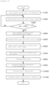
- FIG. 5 is a flowchart illustrating a method of diagnosing a battery condition using a battery exchange system according to embodiments of the present invention.
- the battery exchange system may check whether a battery pack P in a discharged state is accommodated in the battery accommodating part (operatinon S1000) .
- the battery exchange system may operate the charger 1000 connected to the corresponding battery accommodating part by using a first control signal of the controller 7000 to charge the battery pack P (operatinon S2000) .
- the battery exchange system may control the charger 1000 to stop its operation by using a second control signal from the controller (operatinon S4000).
- the specific reference may be a state of charge (SoC) of the battery pack.
- SoC state of charge
- the battery exchange system may control the discharger 3000 to operate using a third control signal from the controller 7000. Accordingly, the battery exchange system may discharge the battery pack P whose charging is stopped by the second control signal (operatinon S5000).
- the discharger 3000 may discharge the battery pack P by outputting a pulse type signal waveform in which a change of the discharge current is clearly shown.
- the battery exchange system may operate the measuring device 5000 using a fourth control signal from the controller 7000. Accordingly, the battery exchange system may measure at least one state information of the battery pack in a discharged state (operatinon S6000).
- the at least one state information may include at least one of a voltage (V), a current (I), and a temperature (T), as described above.
- the battery exchange system may store at least one measured state information in the battery condition diagnosing server S (operation S7000).
- the battery exchange system may operate the charger 1000 according to a first control signal from the controller 7000 to recharge the specific battery pack P whose charging has been stopped, until it is fully charged (operation S8000).
- the battery exchange system may calculate impedance information of the battery pack P by using at least one piece of state information stored in the battery condition diagnosing server S (operation S9000).
- the battery exchange system may calculate the state of health (SoH) of the battery pack P based on the impedance information of the battery pack P by using the battery condition diagnosing server S (operation S10000).
- SoH state of health
- the battery exchange system may calculate a change in the internal resistance of the battery pack P according to the impedance change of the battery pack P. Then, the battery exchange system may calculate the state of health (SoH) of the battery pack P based on the calculated change in internal resistance. For example, when the internal resistance increases, the lifespan of the battery pack may be shortened, and thus the state of health (SoH) of the battery pack may be worse.
- SoH state of health
- the battery exchange system may determine whether the battery pack is defective based on the impedance information of the battery pack P, using the battery condition diagnosing server S (operation S11000).
- the battery exchange system may use the battery condition diagnosing server S to compare the state of health (SoH) of the battery pack (P) calculated from the impedance change of the battery pack (P) with that of a reference battery pack under the same conditions.
- SoH state of health
- the battery condition diagnosing server (S) may determine that a defect has occurred in the specific battery pack (P).
- the defect may include a defect caused by a battery cell, an electric device or an appliance including the battery cell.
- the embodiments of the present disclosure provide a battery swapping apparatus, an apparatus (server) for diagnosing a battery condition, a method for diagnosing a battery condition, and a battery exchange system including the battery swapping apparatus and the apparatus for diagnosing a battery condition with high-efficiency and high-reliability.
- the battery exchange system may discharge a battery pack in which charging has been stopped, measure at least one state information of the discharged battery pack, resume charging of the battery pack, calculate the impedance information from the at least one state information of the discharged battery pack, and determine a state of health (SoH) of the battery pack and whether the battery pack is defective.
- SoH state of health
- the embodiments of the present disclosure may be implemented as program instructions executable by a variety of computers and recorded on a computer readable medium.
- the computer readable medium may include a program instruction, a data file, a data structure, or a combination thereof.
- the program instructions recorded on the computer readable medium may be designed and configured specifically for the present disclosure or can be publicly known and available to those who are skilled in the field of computer software.
- Examples of the computer readable medium may include a hardware device such as ROM, RAM, and flash memory, which are specifically configured to store and execute the program instructions.
- Examples of the program instructions include machine codes made by, for example, a compiler, as well as high-level language codes executable by a computer, using an interpreter.
- the above exemplary hardware device can be configured to operate as at least one software module in order to perform the embodiments of the present disclosure, and vice versa.
Landscapes
- Engineering & Computer Science (AREA)
- Power Engineering (AREA)
- Transportation (AREA)
- Mechanical Engineering (AREA)
- Life Sciences & Earth Sciences (AREA)
- Sustainable Development (AREA)
- Sustainable Energy (AREA)
- Physics & Mathematics (AREA)
- General Physics & Mathematics (AREA)
- Chemical & Material Sciences (AREA)
- Manufacturing & Machinery (AREA)
- Chemical Kinetics & Catalysis (AREA)
- Electrochemistry (AREA)
- General Chemical & Material Sciences (AREA)
- Secondary Cells (AREA)
- Charge And Discharge Circuits For Batteries Or The Like (AREA)
- Health & Medical Sciences (AREA)
- General Health & Medical Sciences (AREA)
- Medical Informatics (AREA)
- Tests Of Electric Status Of Batteries (AREA)
Abstract
Description
- This application claims priority to and the benefit of
Korean Patent Application No.10-2021-0119789 filed in the Korean Intellectual Property Office on September 08, 2021 - The present invention relates to a battery swapping apparatus, an apparatus for diagnosing battery condition, a system including the same, and a method for diagnosing battery condition, and more particularly, to a battery swapping apparatus, an apparatus for diagnosing battery condition, a system including the same, and a method for diagnosing battery condition by measuring impedance of a battery pack in real time along with charging the battery pack to determine a state of health and a defect of a battery pack.
- Conventionally, a voltage, a current, and a temperature of a battery pack are separately measured in order to estimate a state of health of the battery pack. However, the conventional method for measuring a state of health of a battery pack has a disadvantage in that an error range of measurement result is large, and thus a capacity of a battery pack is excessively estimated. Accordingly, a problem occurs in that a battery life is shortened compared to the estimated capacity of the battery.
- In addition, a conventional apparatus for estimating a state of health of a battery pack makes it difficult to detect a fire or an explosion in advance because it is difficult to diagnose internal defects in a battery cell, an appliance or an electronic device including the battery cell.
- Accordingly, recently, a method of measuring impedance of a battery has been provided in order to accurately estimate a state of health of a battery pack and diagnose defects.
- However, it is difficult to diagnose a battery pack defect occurring during use of the battery pack since it is difficult to measure impedance of the battery pack in real time with an existing impedance measurement method.
- Accordingly, example embodiments of the present disclosure are provided to substantially obviate one or more problems due to limitations and disadvantages of the related art.
- Embodiments of the present disclosure provide a battery swapping apparatus with high efficiency and high reliability, wherein the battery swapping apparatus is configured to measure state information of a battery pack.
- Embodiments of the present disclosure also provide a battery diagnosing server with high efficiency and high reliability, wherein the battery diagnosing server is configured to calculate impedance from state information of the battery pack and determines a state of health (SoH) of the battery pack and whether the battery pack is defective.
- Embodiments of the present disclosure also provide a method for diagnosing a condition of a battery pack with high efficiency and high reliability, wherein the battery exchange method calculates impedance from state information of the battery pack and determines a state of health (SoH) of the battery pack and whether the battery pack is defective.
- Embodiments of the present disclosure also provide a battery exchange system with high efficiency and high reliability, wherein the battery exchange system is configured to calculate impedance from state information of the battery pack and determines a state of health (SoH) of the battery pack and whether the battery pack is defective.
- In order to achieve the objective of the present disclosure, a battery swapping apparatus including at least one battery accommodating part for charging a battery pack, the apparatus may comprise: a charger configured to charge the battery pack; a discharger configured to discharge the battery pack; a measuring device configured to measure at least one state information of the battery pack; and a controller configured to stop operation of the charger in case a state of charge of the battery pack reaches a predetermined reference value, to control the discharger to operate, and to acquire state information of the battery pack in a discharged state using the measuring device.
- The controller may be configured to, upon a measurement of the state information of the battery pack in the discharged state being completed, control the charger to resume charging so that the battery pack is fully charged.
- The controller may be in connection with an external server and the controller is configured to transmit the at least one state information of the battery pack to the external server.
- The state information of the battery pack may include at least one of a voltage (V), a current (I) and a temperature (T) of the battery pack.
- The discharger may be configured to discharge the battery pack by outputting a pulse type discharge current.
- According to another embodiment of the present disclosure, an apparatus for diagnosing a condition of a battery pack using at least one state information of the battery pack, may comprise: at least one processor; and a memory for storing at least one instruction executed by the at least one processor, wherein the at least one instruction includes: an instruction to receive and store at least one state information of the battery pack; an instruction to calculate impedance information based on the at least one state information of the battery pack; and an instruction to calculate a state of health (SoH) of the battery pack from the impedance information.
- The at least one state information of the battery pack may be obtained from a battery swapping apparatus.
- The state information of the battery pack may include at least one of a voltage (V), a current (I) and a temperature (T) of the battery pack.
- The instruction to calculate a state of health (SoH) of the battery pack from the impedance information includes: an instruction to calculate a change in internal resistance of the battery pack from at least one state information of the battery pack; and an instruction to calculate a state of health of the battery pack based on the change in internal resistance of the battery pack.
- Here, the at least one instruction may further include an instruction to determine whether to diagnose a defect of the battery pack based on the state of health of the battery pack.
- The instruction to determine whether to diagnose a defect of the battery pack may include: an instruction to compare the state of health of the battery pack with a reference state of health of a battery pack under the same conditions; and an instruction to determine that a defect has occurred in the battery pack when a difference of more than a threshold value occurs in the state of health of the battery pack compared to the reference state of health.
- According to another embodiment of the present disclosure, a method for diagnosing a condition of a battery pack using at least one state information of the battery pack, the method may comprise: receiving and storing at least one state information of the battery pack; calculating impedance information based on at least one state information of the battery pack; and calculating a state of health (SoH) of the battery pack from the impedance information.
- The at least one state information of the battery pack may be obtained from a battery swapping apparatus.
- The state information of the battery pack may include at least one of a voltage (V), a current (I) and a temperature (T) of the battery pack.
- The calculating the state of health (SoH) may include: calculating a change in internal resistance of the battery pack from at least one state information of the battery pack; and calculating a state of health of the battery pack based on change in the internal resistance of the battery pack.
- The method may further comprise determining whether to diagnose a defect of the battery pack based on the state of health of the battery pack.
- The determining whether to diagnose a defect of the battery pack may include: comparing the state of health of the battery pack with a reference state of health of a battery pack under the same conditions; and determining that a defect has occurred in the battery pack when a difference of more than a threshold value occurs in the state of health of the battery pack compared to the reference state of health.
- According to another embodiment of the present disclosure, a battery exchange system charging a battery pack accommodated in at least one battery accommodating part and diagnosing a state of the battery pack, the system may comprise: a battery swapping apparatus configured to stop charging of the battery pack, measure at least one piece of state information, and resume charging of the battery pack; and a server for diagnosing battery condition configured to receive at least one state information of the battery pack from the battery swapping apparatus and calculate impedance of the battery pack.
- The battery swapping apparatus may be configured to stop charging of the battery pack when the stat of charge of the battery pack reaches a predetermined reference value.
- The battery swapping apparatus may be configured to measure the at least one state information by discharging the battery pack of which charging is stopped.
- The server may be configured to calculate a state of health (SoH) of the battery pack by using the impedance information of the battery pack.
- The server may be configured to determine whether the battery pack is defective by using the impedance information of the battery pack.
- A battery swapping apparatus, an apparatus (server) for diagnosing a battery condition, a method for diagnosing a battery condition, and a battery exchange system including the battery swapping apparatus and the apparatus for diagnosing a battery condition, according to the embodiments of the present invention, may discharge a battery pack in which charging has been stopped, calculate at least one state information of the discharged battery pack, resume charging of the battery pack, calculate the impedance information from the at least one state information of the discharged battery pack, and determine a state of health (SoH) of the battery pack and whether the battery pack is defective, with high-efficiency and high-reliability.
- A battery swapping apparatus, an apparatus (server) for diagnosing a battery condition, a method for diagnosing a battery condition, and a battery exchange system including the battery swapping apparatus and the apparatus for diagnosing a battery condition, according to the embodiments of the present invention, may discharge a battery pack in which charging has been stopped, calculate at least one state information of the discharged battery pack, resume charging of the battery pack, calculate the impedance information from the at least one state information of the discharged battery pack, and determine a state of health (SoH) of the battery pack and whether the battery pack is defective, with high-efficiency and high-reliability.
- Example embodiments of the present invention will become more apparent by describing in detail example embodiments of the present invention with reference to the accompanying drawings, in which:
-
FIG. 1 is a block diagram of a conventional battery exchange system. -
FIG. 2 is a block diagram of a battery exchange system according to embodiments of the present invention. -
FIG. 3 is a graph showing a pulse signal waveform of a discharge current of a battery pack according to embodiments of the present invention. -
FIG. 4 is a block diagram of a battery condition diagnosing server according to embodiments of the present invention. -
FIG. 5 is a flowchart illustrating a method of diagnosing a battery condition using a battery exchange system according to embodiments of the present invention. - Example embodiments of the present invention are disclosed herein. However, specific structural and functional details disclosed herein are merely representative for purposes of describing example embodiments of the present invention, and example embodiments of the present invention may be embodied in many alternate forms and should not be construed as limited to example embodiments of the present invention set forth herein.
- Accordingly, while the invention is susceptible to various modifications and alternative forms, specific embodiments thereof are shown by way of example in the drawings and will herein be described in detail. It should be understood, however, that there is no intent to limit the invention to the particular forms disclosed, but on the contrary, the invention is to cover all modifications, equivalents, and alternatives falling within the spirit and scope of the invention. Like numbers refer to like elements throughout the description of the figures.
- It will be understood that, although the terms first, second, etc. may be used herein to describe various elements, these elements should not be limited by these terms. These terms are only used to distinguish one element from another. For example, a first element could be termed a second element, and, similarly, a second element could be termed a first element, without departing from the scope of the present invention. As used herein, the term "and/or" includes any and all combinations of one or more of the associated listed items.
- It will be understood that when an element is referred to as being "connected" or "coupled" to another element, it can be directly connected or coupled to the other element or intervening elements may be present. In contrast, when an element is referred to as being "directly connected" or "directly coupled" to another element, there are no intervening elements present. Other words used to describe the relationship between elements should be interpreted in a like fashion (i.e., "between" versus "directly between", "adjacent" versus "directly adjacent", etc.).
- The terminology used herein is for the purpose of describing particular embodiments only and is not intended to be limiting of the invention. As used herein, the singular forms "a", "an" and "the" are intended to include the plural forms as well, unless the context clearly indicates otherwise. It will be further understood that the terms "comprises", "comprising,", "includes" and/or "including", when used herein, specify the presence of stated features, integers, steps, operations, elements, and/or components, but do not preclude the presence or addition of one or more other features, integers, steps, operations, elements, components, and/or groups thereof.
- Unless otherwise defined, all terms (including technical and scientific terms) used herein have the same meaning as commonly understood by one of ordinary skill in the art to which this invention belongs. It will be further understood that terms, such as those defined in commonly used dictionaries, should be interpreted as having a meaning that is consistent with their meaning in the context of the relevant art and will not be interpreted in an idealized or overly formal sense unless expressly so defined herein.
- It should also be noted that in some alternative implementations, the functions/acts noted in the blocks may occur out of the order noted in the flowcharts. For example, two blocks shown in succession may in fact be executed substantially concurrently or the blocks may sometimes be executed in the reverse order, depending upon the functionality/acts involved.
- Hereinafter, exemplary embodiments of the present invention will be described in detail with reference to the accompanying drawings.
-
FIG. 1 shows a block diagram of a conventional battery exchange system. - Referring to
FIG. 1 , a conventional battery exchange system is provided with a battery swapping apparatus in which a charger is individually connected to a battery accommodating part in which a battery pack is accommodated and an external server for storing a charge amount of the battery pack. - Accordingly, the conventional battery exchange system simply provides only a charging function of a battery pack, and thus cannot take into account a change in impedance of the battery pack, a state of health of the battery pack and presence or absence of defects. Therefore, the conventional battery exchange system shows a low reliability.
- On the other hand, a battery exchange system according to embodiments of the present invention may measure state information along with charging of a battery pack, calculate impedance of the battery pack from the measured state information, determine a state of health using the calculated impedance, and determine presence or absence of defects of the battery pack, thereby providing a high-efficiency and high-reliability battery exchange system.
- A battery exchange system according to embodiments of the present invention will be described in more detail with reference to the following drawings.
-
Fig. 2 is a block diagram of a battery exchange system according to embodiments of the present invention. - Referring to
FIG. 2 , the battery exchange system according to embodiments of the present invention may include a battery swapping apparatus (D) and an external battery condition diagnosing server (S). Here, the battery swapping apparatus may be referred to as a battery swapping staiton. - More specifically, the battery swapping apparatus (D) may be connected with an external battery condition diagnosing server(S) through external communication. Accordingly, the battery exchange system may control charging of the battery packs (P) accommodated in a battery accommodating part by the battery swapping apparatus (D) and measure at least one state information of the battery packs (P). The external battery condition diagnosing server (S) may determine and provide impedance information, a state of health (SoH), and defects of the battery packs P based on the measured state information of at least one of the battery packs P.
- As to more specifics of the components (D, S) of the battery exchange system according to embodiments of the present invention, the battery swapping apparatus (D) may include at least one battery accommodating part.
- The battery accommodating part may accommodate the battery packs P inserted from outside by a user. Accordingly, the battery swapping apparatus D may charge at least one battery pack P accommodated in the battery accommodating part and diagnose whether the battery pack P being charged is defective in real time.
- Furthermore, the battery swapping apparatus D may provide a user with a battery pack P that has been fully charged among the battery packs P accommodated in the at least one battery accommodating part.
- The battery swapping apparatus D may include a
charger 1000, adischarger 3000, ameasuring device 5000, and acontroller 7000. - Here, the
charger 1000, thedischarger 3000, and themeasuring device 5000 may be connected in parallel, and thecharger 1000, thedischarger 3000, and themeasuring device 5000 may be connected to thecontroller 7000 through internal communication, respectively. According to embodiments, the internal communication may be provided by any one of Universal Asynchronous Receiver/Transmitter (UART), Controller Area Network (CAN), Local Interconnect Network (LIN), and Ethernet. - At least one
charger 1000 may be provided in the battery swapping apparatus D to charge at least one battery pack P accommodated in the battery accommodating parts. Here, the battery pack P is a device for storing energy and may be applied to at least one electric device to provide power to the electric device. For example, the at least one electric device may be any one of an electric scooter, a kickboard, a car, a robot, or a drone. - According to an embodiment, when at least one battery pack P is accommodated in battery accommodating parts, at least one
charger 1000 may be individually connected to the at least one battery pack P. In other words,chargers 1000 may be 1 to 1 connected to battery packs P. - For example, to be more specific, when N battery packs P and
N chargers 1000 are provided, the (+) terminal and the (-) terminal of thefirst charger 1000 are conneced to the (+) terminal and the (-) terminal of the battery accommodating part in which the first battery pack P1 is accommodated. In addition, the (+) terminal and the (-) terminal of theNth charger 1000 are conneced to the (+) terminal and the (-) terminal of the battery accommodating part in which the Nth battery pack PN is accommodated. - When the
charger 1000 receives a first control signal from acontroller 7000, which will be described later, the charger may convert AC power provided to the battery swapping apparatus D to DC power and charge a specific battery pack P that is individually connected to the charger. - Furthermore, upon receiving a second control signal from the
controller 7000, which will be described later, thecharger 1000 may stop charging the specific battery pack P being charged. According to an embodiment, thecontroller 7000 may transmit a second control signal to thecharger 1000 when a charge amount of the battery pack P being charged satisfies a specific reference value. Accordingly, thecharger 1000 may stop charging the battery pack P being charged. For example, the second control signal may be transmitted when a state of charge of the battery pack P reaches 50% or more. - At least one
discharger 3000 may be provided in the battery swapping apparatus D to discharge at least one battery pack P accommodated in the battery accommodating parts. - To be more specific, when at least one battery pack P is accommodated in battery accommodating parts, at least one
discharger 3000 may be individually connected to at least one battery packs P. In other words,dischargers 3000 may be 1 to 1 connected to battery packs P. - For example, to be more specific, when N battery packs P and
N dischargers 3000 are provided, the (+) terminal and the (-) terminal of thefirst discharger 3000 are conneced to the (+) terminal and the (-) terminal of the battery accommodating part in which the first battery pack P1 is accommodated. In addition, the (+) terminal and the (-) terminal of theNth discharger 3000 are conneced to the (+) terminal and the (-) terminal of the battery accommodating part in which the Nth battery pack PN is accommodated. - When the
discharger 3000 receives a third control signal from thecontroller 7000, which will be described later, thedischarger 3000 may discharge a specific battery pack P which is individually connected to the discharger. - According to an embodiment, the
discharger 3000 may receive a third control signal from thecontroller 7000. More specifically, thedischarger 3000 may receive the third control signal from thecontroller 7000 after a state of charge of the battery pack P satisfies a specific reference value and charging is stopped. - The
discharger 3000 may discharge the battery pack P upon receiving the third control signal from thecontroller 7000. - In this instance, the
discharger 3000 may discharge the battery pack P using a discharge current to be output as a pulse signal waveform. -
FIG. 3 is a graph showing a pulse signal waveform of a discharge current of a battery pack according to embodiments of the present invention. - Referring to
FIG. 3 , thedischarger 3000 may adjust at least one parameter among an amplitude, a period, and a frequency of a discharge current so that the discharge current of a battery pack P has various pulse waveforms. - According to an exemplary embodiment, the
discharger 3000 may discharge the battery pack P so that the discharge current is output in one cycle within 10 seconds at a 0.5 C-rate. - According to another exemplary embodiment, the
discharger 3000 may discharge the battery pack P so that the discharge current is output in three cycles within 20 seconds at a 1 C-rate. - Here, the C-rate may be defined as an amount that can be discharged during a corresponding time when the battery pack is discharged at a specific constant current. For example, when using a battery pack having a charge capacity of 3000 mA/h, the
discharger 3000 may output a maximum discharge current of 3000mA at 1 C-rate. - However, the disclosure is not limited thereto, and the battery swapping apparatus D may output a charging current in a pulse type signal by controlling the
charger 1000 instead of thedischarger 3000 . - Referring back to
FIG. 1 , themeasuring device 5000 may measure at least one state information of the battery pack P upon receiving a fourth control signal from thecontroller 7000. - More specifically, according to an embodiment, when at least one battery pack P is accommodated in battery accomodating parts, the at least one
measuring device 5000 may be individually connected to the at least one battery pack P. In other words, the measuringdevices 5000 may be 1:1 connected to battery packs P. - For example, to be more specific, when N battery packs P and
N measuring devices 5000 are provided, the (+) terminal and the (-) terminal of thefirst measuring device 5000 are conneced to the (+) terminal and the (-) terminal of the battery accommodating part in which the first battery pack P1 is accommodated. In addition, the (+) terminal and the (-) terminal of theNth measuring devices 5000 are conneced to the (+) terminal and the (-) terminal of the battery accommodating part in which the Nth battery pack PN is accommodated. - However, the measuring
devices 5000 may be provided in a single device without being limited thereto. More specifically, onemeasuring device 5000 may be connected to at least one switch (not shown) connected to at least one battery pack P. Accordingly, themeasuring device 5000 may measure the state information of at least one battery pack P connected 1 to 1 with the at least one switch according to On/Off operation of the at least one switch. - As described above, upon receiving a fourth control signal from the
controller 7000, which will be described later, themeasuring device 5000 may measure at least one state information of the specific battery pack P which is individually connected to the measuring device. - In more detail according to the embodiment, the
measuring device 5000 may receive the fourth control signal from thecontroller 7000. Here, the fourth control signal may be transmitted after the third control signal is transmitted by thecontroller 7000. In other words, themeasuring device 5000 may measure at least one state information of a specific battery pack P in a discharged state. For example, the at least one state information may include at least one of a voltage (V), a current (I), and a temperature (T). - Thereafter, the
measuring device 5000 may transmit at least one measured state information to thecontroller 7000, to be described later. - As described above, the
controller 7000 may be connected to thecharger 1000, thedischarger 3000, and themeasuring device 5000 through internal communication, respectively. Accordingly, thecontroller 7000 may transmit operation control signals to thecharger 1000, thedischarger 3000, and themeasuring device 5000, and may receive at least one measurement information from thecharger 1000, thedischarger 3000, and themeasuring device 5000. - According to an embodiment, when a battery pack P is accommodated in at least one battery accommodating part, the
controller 7000 may transmit a first control signal to thecharger 1000 connected to a corresponding battery accommodating part. Here, the first control signal may be a control signal for starting an operation of thecharger 1000. - According to another embodiment, when a state of charge (SoC) of the battery pack P reaches a specific reference value during the operation of the
charger 1000 according to the first control signal, thecontroller 7000 may transmit a second control signal to thecharger 1000. Here, the second control signal may be a control signal for stopping the operation of thecharger 1000, and a specific reference value of state of charge (SoC) of a specific battery pack may be 50%. - In other words, when a state of charge (SoC) of a specific battery pack is 50% or more, the
controller 7000 may transmit the second control signal to thecharger 1000 to stop charging of the specific battery pack P. - Furthermore, after transmitting the second control signal to the
charger 1000, thecontroller 7000 may transmit a third control signal to thedischarger 3000 connected in parallel with thecharger 1000. - Here, the third control signal is a signal for controlling operation of the
discharger 3000. Upon receiving the third control signal, thedischarger 3000 may output a pulse type discharge current to the battery pack P whose charging is stopped by the second control signal. - Thereafter, the
controller 7000 may transmit a fourth control signal to themeasuring device 5000 connected in parallel with thecharger 1000 and thedischarger 3000. In other words, thecontroller 7000 may operate themeasuring device 5000 and receive at least one state information of the specific battery pack P measured by themeasuring device 5000. - Furthermore, the
controller 7000 may be connected to a battery condition diagnosing server S to be described later by an external communication. Here, the external communication may be at least one of wired/wireless communication such as Ethernet, 3G, 4G, and 5G. - The
controller 7000 may be connected to the external battery condition diagnosing server S and transmit state information of the specific battery pack P received from themeasuring device 5000 to the battery condition diagnosing server S. Thereafter, thecontroller 7000 may receive impedance information of the specific battery pack P calculated from the external battery condition diagnosing server S. - Here, the impedance information of the specific battery pack P may be calculated using the state information of the specific battery pack P by the external battery condition diagnosis server device S.
- Thereafter, the
controller 7000 may transmit a first control signal to thecharger 1000 connected to the specific battery pack P. Accordingly, thecharger 1000 may resume charging of the specific battery pack P in which charging has been stopped, thereby fully charging the specific battery pack P. - The battery condition diagnosing server S may be linked with the
controller 7000 through external communication. Accordingly, the battery condition diagnosing server S may store at least one state information of the specific battery pack P received from thecontroller 7000. Here, the state information may include voltage (V), current (I), and temperature (T) information of the specific battery pack P, as described above. - The battery condition diagnosing server S may use the received state information of the specific battery pack P to diagnose a condition of the battery pack P in real time.
- More specifically, the battery condition diagnosing server S may calculate impedance information of the specific battery pack P by using the state information of the specific battery pack P received by the
controller 7000. - The battery condition diagnosing server S may store the calculated impedance information of the specific battery pack P and transmit the impedance information to the
controller 7000. - The battery condition diagnosing server S may calculate a state of health (SoH) of the specific battery pack P based on impedance information of the battery pack P.
- According to an embodiment, the battery condition diagnosing server S may calculate a change in internal resistance of the specific battery pack P according to a change in the impedance of the specific battery pack P.
- Thereafter, the battery condition diagnosing server S may calculate the state of health of the specific battery pack P from the calculated change in internal resistance. For example, when the internal resistance increases, the lifespan of the specific battery pack P may be shortened, and thus the state of health (SoH) may be worse.
- Also, the battery condition diagnosing server S may determine whether the battery pack of the specific battery pack P is defective based on the impedance information of the specific battery pack P.
- More specifically, according to embodiments, the battery condition diagnosing server S may compare the SoH of the specific battery pack P with a SoH of a reference battery pack under the same conditions.
- Here, when a difference of the SoH of the specific battery pack (P) and the reference SoH is more than a threshold value, the battery condition diagnosing server (S) may determine that a defect has occurred in the specific battery pack (P). Here, the defect may include a defect caused by a battery cell, an electric device or an appliance including the battery cell.
-
FIG. 4 is a block diagram of a battery condition diagnosing server according to embodiments of the present invention. - Referring to
FIG. 4 , the battery condition diagnosing server S may include amemory 100, aprocessor 200, atransceiver 300, aninput interface 400, anoutput interface 500, and astorage device 600. - Each of the
components bus 700 to communicate with each other. - Among the
components memory 100 and thestorage device 600 may consist of at least one of a volatile storage medium and a non-volatile storage medium. For example, thememory 100 and thestorage device 600 may include at least one of a read only memory (ROM) and a random access memory (RAM). - Among them, the
memory 100 may include at least one instruction executed by theprocessor 200. - According to embodiments, the at least one instruction may include an instruction to receive and store at least one state information of the battery pack, an instruction to calculate impedance information from at least one state information of the battery pack, and an instruction to calculate a state of health (SoH) of the battery pack from the impedance information.
- The
processor 200 may mean a central processing unit (CPU), a graphics processing unit (GPU), or a dedicated processor on which methods according to embodiments of the present invention are performed. - As described above, the
processor 200 may execute at least one program instruction stored in thememory 100 . - In the above, a battery exchange system including a battery swapping apparatus and a battery condition diagnosing server according to embodiments of the present invention has been described. Hereinafter, a method of diagnosing a battery state using a battery exchange system will be described in more detail.
-
FIG. 5 is a flowchart illustrating a method of diagnosing a battery condition using a battery exchange system according to embodiments of the present invention. - Referring to
FIG. 5 , the battery exchange system may check whether a battery pack P in a discharged state is accommodated in the battery accommodating part (operatinon S1000) . - In the inatance that a battery pack P is accommodated in at least one battery accommodating part, the battery exchange system may operate the
charger 1000 connected to the corresponding battery accommodating part by using a first control signal of thecontroller 7000 to charge the battery pack P (operatinon S2000) . - Thereafter, when a state of the battery pack P being charged by the first control signal reaches a threshold of a specific reference (operatinon S3000), the battery exchange system may control the
charger 1000 to stop its operation by using a second control signal from the controller (operatinon S4000). Here, the specific reference may be a state of charge (SoC) of the battery pack. In other words, when the charge amount (SoC) of the battery pack P being charged is 50% or more, the battery exchange system may stop the operation of thecharger 1000 using the second control signal from thecontroller 7000. - Thereafter, the battery exchange system may control the
discharger 3000 to operate using a third control signal from thecontroller 7000. Accordingly, the battery exchange system may discharge the battery pack P whose charging is stopped by the second control signal (operatinon S5000). Here, thedischarger 3000 may discharge the battery pack P by outputting a pulse type signal waveform in which a change of the discharge current is clearly shown. - Thereafter, the battery exchange system may operate the
measuring device 5000 using a fourth control signal from thecontroller 7000. Accordingly, the battery exchange system may measure at least one state information of the battery pack in a discharged state (operatinon S6000). Here, the at least one state information may include at least one of a voltage (V), a current (I), and a temperature (T), as described above. - Thereafter, the battery exchange system may store at least one measured state information in the battery condition diagnosing server S (operation S7000).
- Meanwhile, the battery exchange system may operate the
charger 1000 according to a first control signal from thecontroller 7000 to recharge the specific battery pack P whose charging has been stopped, until it is fully charged (operation S8000). - Furthermore, the battery exchange system may calculate impedance information of the battery pack P by using at least one piece of state information stored in the battery condition diagnosing server S (operation S9000).
- The battery exchange system may calculate the state of health (SoH) of the battery pack P based on the impedance information of the battery pack P by using the battery condition diagnosing server S (operation S10000).
- In more detail according to an embodiment, the battery exchange system may calculate a change in the internal resistance of the battery pack P according to the impedance change of the battery pack P. Then, the battery exchange system may calculate the state of health (SoH) of the battery pack P based on the calculated change in internal resistance. For example, when the internal resistance increases, the lifespan of the battery pack may be shortened, and thus the state of health (SoH) of the battery pack may be worse.
- In addition, the battery exchange system may determine whether the battery pack is defective based on the impedance information of the battery pack P, using the battery condition diagnosing server S (operation S11000).
- More specifically, according to an embodiment, the battery exchange system may use the battery condition diagnosing server S to compare the state of health (SoH) of the battery pack (P) calculated from the impedance change of the battery pack (P) with that of a reference battery pack under the same conditions.
- Here when a difference of the SoH of the specific battery pack (P) and the reference SoH is more than a threshold value, the battery condition diagnosing server (S) may determine that a defect has occurred in the specific battery pack (P). Here, the defect may include a defect caused by a battery cell, an electric device or an appliance including the battery cell.
- As described above, the embodiments of the present disclosure provide a battery swapping apparatus, an apparatus (server) for diagnosing a battery condition, a method for diagnosing a battery condition, and a battery exchange system including the battery swapping apparatus and the apparatus for diagnosing a battery condition with high-efficiency and high-reliability. The battery exchange system may discharge a battery pack in which charging has been stopped, measure at least one state information of the discharged battery pack, resume charging of the battery pack, calculate the impedance information from the at least one state information of the discharged battery pack, and determine a state of health (SoH) of the battery pack and whether the battery pack is defective.
- The embodiments of the present disclosure may be implemented as program instructions executable by a variety of computers and recorded on a computer readable medium. The computer readable medium may include a program instruction, a data file, a data structure, or a combination thereof. The program instructions recorded on the computer readable medium may be designed and configured specifically for the present disclosure or can be publicly known and available to those who are skilled in the field of computer software.
- Examples of the computer readable medium may include a hardware device such as ROM, RAM, and flash memory, which are specifically configured to store and execute the program instructions. Examples of the program instructions include machine codes made by, for example, a compiler, as well as high-level language codes executable by a computer, using an interpreter. The above exemplary hardware device can be configured to operate as at least one software module in order to perform the embodiments of the present disclosure, and vice versa.
- While the example embodiments of the present invention and their advantages have been described in detail, it should be understood that various changes, substitutions and alterations may be made herein without departing from the scope of the invention.
Claims (22)
- A battery swapping apparatus including at least one battery accommodating part for charging a battery pack, the apparatus comprising:a charger configured to charge the battery pack;a discharger configured to discharge the battery pack;a measuring device configured to measure at least one state information of the battery pack; anda controller configured to stop operation of the charger in case a state of charge of the battery pack reaches a predetermined reference value, to control the discharger to operate, and to acquire state information of the battery pack in a discharged state using the measuring device.
- The battery swapping apparatus of claim 1, wherein, upon a measurement of the state information of the battery pack in the discharged state being completed, the controller is configured to control the charger to resume charging so that the battery pack is fully charged.
- The battery swapping apparatus of claim 1, wherein the controller is in connection with an external server and the controller is configured to transmit the at least one state information of the battery pack to the external server.
- The battery swapping apparatus of claim 1, wherein the state information of the battery pack includes at least one of a voltage (V), a current (I) and a temperature (T) of the battery pack.
- The battery swapping apparatus of claim 1, wherein the discharger is configured to discharge the battery pack by outputting a pulse type discharge current.
- An apparatus for diagnosing a condition of a battery pack using at least one state information of the battery pack, comprising:at least one processor; anda memory for storing at least one instruction executed by the at least one processor,wherein the at least one instruction includes:an instruction to receive and store at least one state information of the battery pack;an instruction to calculate impedance information based on the at least one state information of the battery pack; andan instruction to calculate a state of health (SoH) of the battery pack from the impedance information.
- The apparatus of claim 6, wherein the at least one state information of the battery pack is obtained from a battery swapping apparatus.
- The apparatus of claim 6, wherein the state information of the battery pack includes at least one of a voltage (V), a current (I) and a temperature (T) of the battery pack.
- The apparatus of claim 6, wherein the instruction to calculate a state of health (SoH) of the battery pack from the impedance information includes:an instruction to calculate a change in internal resistance of the battery pack from at least one state information of the battery pack; andan instruction to calculate a state of health of the battery pack based on the change in internal resistance of the battery pack.
- The apparatus of claim 6, wherein the at least one instruction further includes an instruction to determine whether to diagnose a defect of the battery pack based on the state of health of the battery pack.
- The apparatus of claim 10, wherein the instruction to determine whether to diagnose a defect of the battery pack includes:an instruction to compare the state of health of the battery pack with a reference state of health of a battery pack under the same conditions; andan instruction to determine that a defect has occurred in the battery pack when a difference of more than a threshold value occurs in the state of health of the battery pack compared to the reference state of health.
- A method for diagnosing a condition of a battery pack using at least one state information of the battery pack, the method comprising:receiving and storing at least one state information of the battery pack;calculating impedance information based on at least one state information of the battery pack; andcalculating a state of health (SoH) of the battery pack from the impedance information.
- The method of claim 12, wherein the at least one state information of the battery pack is obtained from a battery swapping apparatus.
- The method of claim 12, wherein the state information of the battery pack includes at least one of a voltage (V), a current (I) and a temperature (T) of the battery pack.
- The method of claim 12, wherein the calculating the state of health (SoH) includes:calculating a change in internal resistance of the battery pack from at least one state information of the battery pack; andcalculating a state of health of the battery pack based on a change in the internal resistance of the battery pack.
- The method of claim 12, further comprising:
determining whether to diagnose a defect of the battery pack based on the state of health of the battery pack. - The method of claim 16, wherein the determining whether to diagnose a defect of the battery pack includes:comparing the state of health of the battery pack with a reference state of health of a battery pack under the same conditions; anddetermining that a defect has occurred in the battery pack when a difference of more than a threshold value occurs in the state of health of the battery pack compared to the reference state of health.
- A battery exchange system charging a battery pack accommodated in at least one battery accommodating part and diagnosing a state of the battery pack, the system comprising:a battery swapping apparatus configured to stop charging of the battery pack, measure at least one piece of state information, and resume charging of the battery pack; anda server for diagnosing battery condition configured to receive at least one state information of the battery pack from the battery swapping apparatus and calculate impedance of the battery pack.
- The battery exchange system of claim 18, wherein the battery swapping apparatus is configured to stop charging of the battery when the stat of charge of the battery pack reaches a predetermined reference value.
- The battery exchange system of claim 18, wherein the battery swapping apparatus is configured to measure the at least one state information by discharging the battery pack of which charging is stopped.
- The battery exchange system of claim 18, wherein the server is configured to calculate a state of health (SoH) of the battery pack by using the impedance information of the battery pack.
- The battery exchange system of claim 18, wherein the server is configured to determine whether the battery pack is defective by using the impedance information of the battery pack.
Applications Claiming Priority (2)
| Application Number | Priority Date | Filing Date | Title |
|---|---|---|---|
| KR1020210119789A KR20230037096A (en) | 2021-09-08 | 2021-09-08 | Battery exchanging apparatus, apparatus and method for diagnosing battery states and system using the same |
| PCT/KR2022/010421 WO2023038275A1 (en) | 2021-09-08 | 2022-07-18 | Battery replacement device, battery state diagnosis server device and method, and battery replacement system comprising same |
Publications (3)
| Publication Number | Publication Date |
|---|---|
| EP4234315A1 true EP4234315A1 (en) | 2023-08-30 |
| EP4234315A4 EP4234315A4 (en) | 2024-05-22 |
| EP4234315B1 EP4234315B1 (en) | 2026-05-20 |
Family
ID=85506711
Family Applications (1)
| Application Number | Title | Priority Date | Filing Date |
|---|---|---|---|
| EP22867544.3A Active EP4234315B1 (en) | 2021-09-08 | 2022-07-18 | BATTERY REPLACEMENT DEVICE, SERVER DEVICE FOR BATTERY CONDITION DIAGNOSTIC AND METHOD, AS WELL AS BATTERY REPLACEMENT SYSTEM WITH IT |
Country Status (6)
| Country | Link |
|---|---|
| US (2) | US12392842B2 (en) |
| EP (1) | EP4234315B1 (en) |
| JP (1) | JP7643796B2 (en) |
| KR (1) | KR20230037096A (en) |
| CN (1) | CN116601039A (en) |
| WO (1) | WO2023038275A1 (en) |
Families Citing this family (5)
| Publication number | Priority date | Publication date | Assignee | Title |
|---|---|---|---|---|
| EP3890094A4 (en) * | 2018-11-29 | 2022-05-11 | Honda Motor Co., Ltd. | BATTERY USAGE SYSTEM, CHARGER DEVICE, INFORMATION PROCESSING DEVICE, BATTERY USAGE METHOD, PROGRAM, AND INFORMATION HOLDER |
| JP7540403B2 (en) | 2021-06-29 | 2024-08-27 | 株式会社デンソー | Battery measurement device and battery measurement method |
| CN118922730A (en) * | 2021-12-29 | 2024-11-08 | 福特全球技术公司 | Techniques for detecting battery cell degradation and impending battery pack failure using a battery charger and battery management system |
| JP7775720B2 (en) * | 2022-01-20 | 2025-11-26 | 株式会社デンソー | Secondary Battery System |
| WO2025234572A1 (en) * | 2024-05-09 | 2025-11-13 | 주식회사 엘지에너지솔루션 | Battery management device and battery management method |
Family Cites Families (46)
| Publication number | Priority date | Publication date | Assignee | Title |
|---|---|---|---|---|
| JP2002330547A (en) | 2001-04-27 | 2002-11-15 | Internatl Business Mach Corp <Ibm> | Electric apparatus for determining battery life, computer device, battery life determination system, battery, and battery life detection method |
| KR100462661B1 (en) | 2002-07-02 | 2004-12-20 | 금호석유화학 주식회사 | Method for evaluating their capacities by calculating mathematically specific elements among resistance elements of equivalent circuit model fitted from impedance spectrum of secondary batteries |
| JP4570991B2 (en) | 2005-03-14 | 2010-10-27 | 富士重工業株式会社 | Battery management system |
| WO2007032382A1 (en) * | 2005-09-16 | 2007-03-22 | The Furukawa Electric Co., Ltd | Secondary cell degradation judgment method, secondary cell degradation judgment device, and power supply system |
| KR101417105B1 (en) | 2008-09-08 | 2014-07-08 | 현대자동차주식회사 | How to measure the battery capacity of a vehicle |
| US20100289447A1 (en) * | 2009-05-18 | 2010-11-18 | Dobson Eric L | System and method for power management of energy storage devices |
| US8965721B2 (en) * | 2009-09-30 | 2015-02-24 | Tesla Motors, Inc. | Determining battery DC impedance |
| JP5586219B2 (en) * | 2009-12-25 | 2014-09-10 | 株式会社東芝 | Diagnostic device, battery pack, and battery value index manufacturing method |
| US10067198B2 (en) | 2010-05-21 | 2018-09-04 | Qnovo Inc. | Method and circuitry to adaptively charge a battery/cell using the state of health thereof |
| KR101160545B1 (en) * | 2011-01-31 | 2012-06-27 | 주식회사티움리서치 | Apparatus for measuring state of health of rechargeable battery |
| US20130043841A1 (en) | 2011-08-17 | 2013-02-21 | Pei-Lun Wei | Circuit and method of measuring voltage of the battery |
| EP2701268A1 (en) | 2012-08-24 | 2014-02-26 | Philip Morris Products S.A. | Portable electronic system including charging device and method of charging a secondary battery |
| US9065280B2 (en) * | 2012-10-02 | 2015-06-23 | Zero Motorcycles, Inc. | System and method of using high energy battery packs |
| KR101916969B1 (en) | 2013-01-22 | 2018-11-08 | 삼성에스디아이 주식회사 | Charging method of battery and battery pack thereof |
| US9506987B2 (en) * | 2013-03-08 | 2016-11-29 | Apple Inc. | Tracking fading battery capacity in a plugged-in portable electronic device |
| CN103293483A (en) * | 2013-05-24 | 2013-09-11 | 杭州电子科技大学 | Lithium battery health condition estimation method based on internal resistance measurement |
| JP5362930B1 (en) * | 2013-07-04 | 2013-12-11 | レスク株式会社 | Battery replacement system and program for electric vehicle |
| CN105378498B (en) | 2013-07-10 | 2017-11-14 | 阿尔卑斯电气株式会社 | State Estimation Method for Electric Storage Device |
| FR3009093B1 (en) * | 2013-07-29 | 2017-01-13 | Renault Sa | ESTIMATING THE AGING CONDITION OF AN ELECTRIC BATTERY |
| CN104198949A (en) * | 2014-09-09 | 2014-12-10 | 上虞安卡拖车配件有限公司 | Battery health state detection method |
| KR102256301B1 (en) | 2015-01-30 | 2021-05-26 | 삼성에스디아이 주식회사 | Charging and Discharging Control System and Method for Battery |
| JPWO2016147722A1 (en) | 2015-03-19 | 2017-12-28 | 日本電気株式会社 | Estimation apparatus, estimation method, and program |
| JP6754222B2 (en) * | 2016-05-27 | 2020-09-09 | 古河電気工業株式会社 | Connection device and network system |
| KR102255523B1 (en) | 2016-06-07 | 2021-05-25 | 주식회사 엘지에너지솔루션 | Battery charging apparatus for increasing battery life and battery charging method of the same |
| KR20180049543A (en) | 2016-11-03 | 2018-05-11 | 주식회사 로코스 | Energy storage system considered extensibility of battery pack and method for controlling therefor |
| KR102035679B1 (en) * | 2016-11-29 | 2019-10-23 | 주식회사 엘지화학 | Method and system for caculating state of health(soh) of a battery |
| JP6683144B2 (en) | 2017-02-07 | 2020-04-15 | トヨタ自動車株式会社 | Battery replacement support system and server used therefor |
| US10613150B2 (en) * | 2017-12-07 | 2020-04-07 | National Chung Shan Institute Of Science And Technology | Battery health state evaluation device and method |
| FR3075469B1 (en) * | 2017-12-20 | 2021-04-30 | Commissariat Energie Atomique | PROCESS FOR MANAGING A STATE OF CHARGE OF A BATTERY LEFT IN STANDING |
| TWI704740B (en) | 2017-12-29 | 2020-09-11 | 英屬開曼群島商睿能創意公司 | Method for providing energy storage devices positioned in a device-exchange station, device-exchange station, and sever |
| KR102749310B1 (en) | 2018-08-08 | 2025-01-02 | 주식회사 민테크 | Apparatus for battery diagnosis |
| KR20200020566A (en) * | 2018-08-17 | 2020-02-26 | (주)엠텍정보기술 | Battery management apparatus capable of diagnosing battery life using electrochemical impedance spectroscopy and method using the same |
| JP6973334B2 (en) | 2018-08-30 | 2021-11-24 | トヨタ自動車株式会社 | Secondary battery deterioration state estimation method and secondary battery system |
| CN112714973B (en) * | 2018-09-20 | 2024-07-02 | 本田技研工业株式会社 | Power storage device management system, storage device, power storage device management method, and storage medium |
| KR102579181B1 (en) | 2018-10-22 | 2023-09-15 | 현대모비스 주식회사 | Dc converter capable of battery condition monitoring and battery condition monitoring method thereof |
| KR102491084B1 (en) | 2018-10-22 | 2023-01-19 | 현대모비스 주식회사 | Apparatus for Monitoring Battery Condition |
| JP7254482B2 (en) * | 2018-11-07 | 2023-04-10 | 古河電気工業株式会社 | Rechargeable battery status detection device and rechargeable battery status detection method |
| PL3900150T3 (en) * | 2018-12-21 | 2026-05-11 | Jt International Sa | Charger with battery state of health estimation |
| KR102168031B1 (en) | 2019-04-01 | 2020-10-21 | 홍용제 | Battery charging and replacing device for electric vehicle |
| US20210031645A1 (en) * | 2019-07-30 | 2021-02-04 | Goodwyn George Reeves | Vehicle Battery Pack and Battery Exchange System |
| WO2021040146A1 (en) * | 2019-08-27 | 2021-03-04 | Samsung Electronics Co., Ltd. | Method and system for determining health parameter of a battery |
| KR102284119B1 (en) | 2019-09-16 | 2021-07-30 | 주식회사 피엠그로우 | Apparatus and method for exchanging battery of an electronic car |
| KR20210077948A (en) * | 2019-12-18 | 2021-06-28 | 주식회사 어스텍 | Method and apparatus for diagnosing soh of battery |
| KR102684808B1 (en) | 2020-03-25 | 2024-07-11 | 주식회사 엘지에너지솔루션 | Battery Pack with a handle which has a loose stopper |
| CN111896880A (en) | 2020-09-01 | 2020-11-06 | 湖州快驴科技有限公司 | Method for detecting service life of lithium ion battery for electric vehicle |
| JP7395540B2 (en) * | 2021-06-01 | 2023-12-11 | 株式会社東芝 | Battery deterioration determination method, battery deterioration determination device, battery management system, battery equipped equipment, and battery deterioration determination program |
-
2021
- 2021-09-08 KR KR1020210119789A patent/KR20230037096A/en not_active Ceased
-
2022
- 2022-07-18 JP JP2023532409A patent/JP7643796B2/en active Active
- 2022-07-18 EP EP22867544.3A patent/EP4234315B1/en active Active
- 2022-07-18 US US18/039,557 patent/US12392842B2/en active Active
- 2022-07-18 WO PCT/KR2022/010421 patent/WO2023038275A1/en not_active Ceased
- 2022-07-18 CN CN202280007402.7A patent/CN116601039A/en active Pending
-
2025
- 2025-08-21 US US19/306,053 patent/US20250370061A1/en active Pending
Also Published As
| Publication number | Publication date |
|---|---|
| US20250370061A1 (en) | 2025-12-04 |
| KR20230037096A (en) | 2023-03-16 |
| WO2023038275A1 (en) | 2023-03-16 |
| EP4234315A4 (en) | 2024-05-22 |
| US12392842B2 (en) | 2025-08-19 |
| JP7643796B2 (en) | 2025-03-11 |
| JP2023551000A (en) | 2023-12-06 |
| EP4234315B1 (en) | 2026-05-20 |
| US20230417837A1 (en) | 2023-12-28 |
| CN116601039A (en) | 2023-08-15 |
Similar Documents
| Publication | Publication Date | Title |
|---|---|---|
| US20250370061A1 (en) | Battery Replacement Device, Battery State Diagnosis Server Device and Method, and Battery Replacement System Comprising Same | |
| US10845417B2 (en) | Battery state estimation device, battery control device, battery system, battery state estimation method | |
| EP2963433B1 (en) | Method and apparatus for estimating state of battery | |
| US9869724B2 (en) | Power management system | |
| KR102856950B1 (en) | Apparatus and method for diagnosing degeneracy of battery | |
| EP2851700B1 (en) | Method and terminal for displaying capacity of battery | |
| US10444296B2 (en) | Control device, control method, and recording medium | |
| JP6101714B2 (en) | Battery control device, battery system | |
| JP2022516753A (en) | Battery diagnostic system and method | |
| JPWO2011121692A1 (en) | Secondary battery deterioration diagnosis method and deterioration diagnosis device | |
| EP2720054A1 (en) | Battery control device and battery system | |
| JP7444846B2 (en) | Rechargeable battery fluid loss detection device and rechargeable battery fluid loss detection method | |
| KR102794109B1 (en) | Apparatus and method for managing battery | |
| JP7237185B2 (en) | BATTERY MANAGEMENT DEVICE AND METHOD, AND BATTERY SYSTEM INCLUDING THE SAME | |
| WO2017056732A1 (en) | Battery control device and battery system | |
| US20150192643A1 (en) | Method and device for determining the actual capacity of a battery | |
| JP2022523930A (en) | Charge state estimation device and method | |
| EP3605123A1 (en) | Storage battery control device and control method | |
| JP5851514B2 (en) | Battery control device, secondary battery system | |
| EP3278125B1 (en) | Apparatus and methods for battery monitoring using discharge pulse measurements | |
| EP4083641A1 (en) | Semiconductor device and method of monitoring battery remaining capacity | |
| KR20140114184A (en) | Mehtod and apparatus for estimating state of charge of battery | |
| EP4726410A1 (en) | Battery diagnostic device and method | |
| EP1199767A1 (en) | Battery operable device with battery state-of-charge indicator | |
| KR20230059648A (en) | Apparatus and method for managing battery |
Legal Events
| Date | Code | Title | Description |
|---|---|---|---|
| STAA | Information on the status of an ep patent application or granted ep patent |
Free format text: STATUS: THE INTERNATIONAL PUBLICATION HAS BEEN MADE |
|
| PUAI | Public reference made under article 153(3) epc to a published international application that has entered the european phase |
Free format text: ORIGINAL CODE: 0009012 |
|
| STAA | Information on the status of an ep patent application or granted ep patent |
Free format text: STATUS: REQUEST FOR EXAMINATION WAS MADE |
|
| 17P | Request for examination filed |
Effective date: 20230525 |
|
| AK | Designated contracting states |
Kind code of ref document: A1 Designated state(s): AL AT BE BG CH CY CZ DE DK EE ES FI FR GB GR HR HU IE IS IT LI LT LU LV MC MK MT NL NO PL PT RO RS SE SI SK SM TR |
|
| A4 | Supplementary search report drawn up and despatched |
Effective date: 20240423 |
|
| RIC1 | Information provided on ipc code assigned before grant |
Ipc: B60L 3/12 20060101ALI20240417BHEP Ipc: H01M 10/42 20060101ALI20240417BHEP Ipc: G01R 31/392 20190101ALI20240417BHEP Ipc: H02J 7/00 20060101ALI20240417BHEP Ipc: B60L 58/12 20190101ALI20240417BHEP Ipc: B60L 58/16 20190101ALI20240417BHEP Ipc: B60L 58/18 20190101ALI20240417BHEP Ipc: B60L 3/00 20190101ALI20240417BHEP Ipc: B60L 53/80 20190101AFI20240417BHEP |
|
| DAV | Request for validation of the european patent (deleted) | ||
| DAX | Request for extension of the european patent (deleted) | ||
| STAA | Information on the status of an ep patent application or granted ep patent |
Free format text: STATUS: EXAMINATION IS IN PROGRESS |
|
| 17Q | First examination report despatched |
Effective date: 20250326 |
|
| REG | Reference to a national code |
Ref country code: DE Ref legal event code: R079 Free format text: PREVIOUS MAIN CLASS: B60L0053800000 Ipc: H01M0010480000 Ref country code: DE Ref legal event code: R079 Ref document number: 602022037332 Country of ref document: DE Free format text: PREVIOUS MAIN CLASS: B60L0053800000 Ipc: H01M0010480000 |
|
| GRAP | Despatch of communication of intention to grant a patent |
Free format text: ORIGINAL CODE: EPIDOSNIGR1 |
|
| STAA | Information on the status of an ep patent application or granted ep patent |
Free format text: STATUS: GRANT OF PATENT IS INTENDED |
|
| RIC1 | Information provided on ipc code assigned before grant |
Ipc: H01M 10/48 20060101AFI20260114BHEP Ipc: B60L 53/80 20190101ALI20260114BHEP Ipc: B60L 3/00 20190101ALI20260114BHEP Ipc: B60L 58/18 20190101ALI20260114BHEP Ipc: B60L 58/16 20190101ALI20260114BHEP Ipc: B60L 58/12 20190101ALI20260114BHEP Ipc: H02J 7/00 20060101ALI20260114BHEP Ipc: G01R 31/392 20190101ALI20260114BHEP Ipc: H01M 10/42 20060101ALI20260114BHEP Ipc: B60L 3/12 20060101ALI20260114BHEP Ipc: H02J 7/84 20260101ALI20260114BHEP |
|
| INTG | Intention to grant announced |
Effective date: 20260130 |
|
| GRAS | Grant fee paid |
Free format text: ORIGINAL CODE: EPIDOSNIGR3 |
|
| GRAA | (expected) grant |
Free format text: ORIGINAL CODE: 0009210 |
|
| STAA | Information on the status of an ep patent application or granted ep patent |
Free format text: STATUS: THE PATENT HAS BEEN GRANTED |
|
| P01 | Opt-out of the competence of the unified patent court (upc) registered |
Free format text: CASE NUMBER: UPC_APP_0010584_4234315/2026 Effective date: 20260320 |