EP4234221A2 - Footwear mold assembly for injection-molding - Google Patents
Footwear mold assembly for injection-molding Download PDFInfo
- Publication number
- EP4234221A2 EP4234221A2 EP23179009.8A EP23179009A EP4234221A2 EP 4234221 A2 EP4234221 A2 EP 4234221A2 EP 23179009 A EP23179009 A EP 23179009A EP 4234221 A2 EP4234221 A2 EP 4234221A2
- Authority
- EP
- European Patent Office
- Prior art keywords
- mold
- plate
- runner
- clause
- thermoplastic elastomer
- Prior art date
- Legal status (The legal status is an assumption and is not a legal conclusion. Google has not performed a legal analysis and makes no representation as to the accuracy of the status listed.)
- Pending
Links
- 238000001746 injection moulding Methods 0.000 title claims abstract description 78
- 239000012530 fluid Substances 0.000 claims description 90
- 238000004891 communication Methods 0.000 claims description 14
- 239000000203 mixture Substances 0.000 description 312
- 229920002725 thermoplastic elastomer Polymers 0.000 description 245
- 239000006260 foam Substances 0.000 description 184
- 229920000642 polymer Polymers 0.000 description 177
- 238000000034 method Methods 0.000 description 140
- 239000000463 material Substances 0.000 description 130
- 239000004088 foaming agent Substances 0.000 description 87
- 239000007789 gas Substances 0.000 description 76
- 229920006346 thermoplastic polyester elastomer Polymers 0.000 description 72
- 238000004519 manufacturing process Methods 0.000 description 64
- 229920001169 thermoplastic Polymers 0.000 description 58
- 239000004416 thermosoftening plastic Substances 0.000 description 54
- 238000002347 injection Methods 0.000 description 51
- 239000007924 injection Substances 0.000 description 51
- 210000004027 cell Anatomy 0.000 description 49
- 238000005187 foaming Methods 0.000 description 47
- 150000002009 diols Chemical class 0.000 description 44
- 229920005992 thermoplastic resin Polymers 0.000 description 44
- 239000006227 byproduct Substances 0.000 description 43
- 239000000047 product Substances 0.000 description 40
- 229920001634 Copolyester Polymers 0.000 description 37
- 230000008569 process Effects 0.000 description 36
- 229920006344 thermoplastic copolyester Polymers 0.000 description 36
- 239000002861 polymer material Substances 0.000 description 35
- 239000000243 solution Substances 0.000 description 35
- 238000002844 melting Methods 0.000 description 34
- 230000008018 melting Effects 0.000 description 34
- 229920000728 polyester Polymers 0.000 description 33
- 239000002699 waste material Substances 0.000 description 28
- 238000000465 moulding Methods 0.000 description 27
- 229920005989 resin Polymers 0.000 description 26
- 239000011347 resin Substances 0.000 description 26
- 230000007547 defect Effects 0.000 description 23
- 238000012360 testing method Methods 0.000 description 23
- IJGRMHOSHXDMSA-UHFFFAOYSA-N Atomic nitrogen Chemical compound N#N IJGRMHOSHXDMSA-UHFFFAOYSA-N 0.000 description 21
- CURLTUGMZLYLDI-UHFFFAOYSA-N Carbon dioxide Chemical compound O=C=O CURLTUGMZLYLDI-UHFFFAOYSA-N 0.000 description 20
- 230000007704 transition Effects 0.000 description 20
- OFOBLEOULBTSOW-UHFFFAOYSA-N Malonic acid Chemical compound OC(=O)CC(O)=O OFOBLEOULBTSOW-UHFFFAOYSA-N 0.000 description 19
- 125000003118 aryl group Chemical group 0.000 description 18
- 230000005484 gravity Effects 0.000 description 18
- 239000000155 melt Substances 0.000 description 18
- 239000008188 pellet Substances 0.000 description 18
- 229920001577 copolymer Polymers 0.000 description 17
- 238000010998 test method Methods 0.000 description 17
- 125000004122 cyclic group Chemical group 0.000 description 16
- -1 poly(ethylene ether) Polymers 0.000 description 16
- 238000001816 cooling Methods 0.000 description 15
- 238000011049 filling Methods 0.000 description 15
- 210000002683 foot Anatomy 0.000 description 14
- 230000001143 conditioned effect Effects 0.000 description 13
- 239000004615 ingredient Substances 0.000 description 13
- 238000005259 measurement Methods 0.000 description 13
- 229920000233 poly(alkylene oxides) Polymers 0.000 description 13
- 229920003023 plastic Polymers 0.000 description 12
- 239000004033 plastic Substances 0.000 description 12
- 238000006073 displacement reaction Methods 0.000 description 11
- 239000000126 substance Substances 0.000 description 11
- 239000001569 carbon dioxide Substances 0.000 description 10
- 229910002092 carbon dioxide Inorganic materials 0.000 description 10
- 238000012669 compression test Methods 0.000 description 10
- 230000003750 conditioning effect Effects 0.000 description 10
- 230000002950 deficient Effects 0.000 description 10
- 210000004744 fore-foot Anatomy 0.000 description 10
- 229910052757 nitrogen Inorganic materials 0.000 description 10
- 238000012545 processing Methods 0.000 description 10
- 230000003213 activating effect Effects 0.000 description 9
- 238000002425 crystallisation Methods 0.000 description 9
- 229920001971 elastomer Polymers 0.000 description 9
- 239000000945 filler Substances 0.000 description 9
- 238000005070 sampling Methods 0.000 description 9
- 230000008025 crystallization Effects 0.000 description 8
- 238000002156 mixing Methods 0.000 description 8
- 229910000831 Steel Inorganic materials 0.000 description 7
- 238000000748 compression moulding Methods 0.000 description 7
- 230000003247 decreasing effect Effects 0.000 description 7
- 239000000806 elastomer Substances 0.000 description 7
- 238000000227 grinding Methods 0.000 description 7
- 238000004064 recycling Methods 0.000 description 7
- 239000010959 steel Substances 0.000 description 7
- RTZKZFJDLAIYFH-UHFFFAOYSA-N Diethyl ether Chemical compound CCOCC RTZKZFJDLAIYFH-UHFFFAOYSA-N 0.000 description 6
- KKEYFWRCBNTPAC-UHFFFAOYSA-N Terephthalic acid Chemical compound OC(=O)C1=CC=C(C(O)=O)C=C1 KKEYFWRCBNTPAC-UHFFFAOYSA-N 0.000 description 6
- 230000000386 athletic effect Effects 0.000 description 6
- 230000006835 compression Effects 0.000 description 6
- 238000007906 compression Methods 0.000 description 6
- 229920001519 homopolymer Polymers 0.000 description 6
- 230000001788 irregular Effects 0.000 description 6
- 125000002496 methyl group Chemical group [H]C([H])([H])* 0.000 description 6
- 210000000452 mid-foot Anatomy 0.000 description 6
- 239000004604 Blowing Agent Substances 0.000 description 5
- 239000005977 Ethylene Substances 0.000 description 5
- 238000009864 tensile test Methods 0.000 description 5
- 238000011144 upstream manufacturing Methods 0.000 description 5
- VGGSQFUCUMXWEO-UHFFFAOYSA-N Ethene Chemical compound C=C VGGSQFUCUMXWEO-UHFFFAOYSA-N 0.000 description 4
- LYCAIKOWRPUZTN-UHFFFAOYSA-N Ethylene glycol Chemical compound OCCO LYCAIKOWRPUZTN-UHFFFAOYSA-N 0.000 description 4
- 239000006057 Non-nutritive feed additive Substances 0.000 description 4
- XAGFODPZIPBFFR-UHFFFAOYSA-N aluminium Chemical compound [Al] XAGFODPZIPBFFR-UHFFFAOYSA-N 0.000 description 4
- 229910052782 aluminium Inorganic materials 0.000 description 4
- WERYXYBDKMZEQL-UHFFFAOYSA-N butane-1,4-diol Chemical compound OCCCCO WERYXYBDKMZEQL-UHFFFAOYSA-N 0.000 description 4
- 125000003178 carboxy group Chemical group [H]OC(*)=O 0.000 description 4
- 239000002666 chemical blowing agent Substances 0.000 description 4
- 238000000354 decomposition reaction Methods 0.000 description 4
- 239000005038 ethylene vinyl acetate Substances 0.000 description 4
- 238000001125 extrusion Methods 0.000 description 4
- 239000001257 hydrogen Substances 0.000 description 4
- 229910052739 hydrogen Inorganic materials 0.000 description 4
- 125000004435 hydrogen atom Chemical group [H]* 0.000 description 4
- 125000002887 hydroxy group Chemical group [H]O* 0.000 description 4
- QQVIHTHCMHWDBS-UHFFFAOYSA-N isophthalic acid Chemical compound OC(=O)C1=CC=CC(C(O)=O)=C1 QQVIHTHCMHWDBS-UHFFFAOYSA-N 0.000 description 4
- 238000011068 loading method Methods 0.000 description 4
- XNGIFLGASWRNHJ-UHFFFAOYSA-N phthalic acid Chemical compound OC(=O)C1=CC=CC=C1C(O)=O XNGIFLGASWRNHJ-UHFFFAOYSA-N 0.000 description 4
- 239000000049 pigment Substances 0.000 description 4
- 239000012815 thermoplastic material Substances 0.000 description 4
- XLYOFNOQVPJJNP-UHFFFAOYSA-N water Chemical compound O XLYOFNOQVPJJNP-UHFFFAOYSA-N 0.000 description 4
- KFZMGEQAYNKOFK-UHFFFAOYSA-N Isopropanol Chemical compound CC(C)O KFZMGEQAYNKOFK-UHFFFAOYSA-N 0.000 description 3
- 230000008901 benefit Effects 0.000 description 3
- 229920001400 block copolymer Polymers 0.000 description 3
- 210000002421 cell wall Anatomy 0.000 description 3
- 230000008859 change Effects 0.000 description 3
- 239000003086 colorant Substances 0.000 description 3
- 238000009833 condensation Methods 0.000 description 3
- 230000005494 condensation Effects 0.000 description 3
- 230000000694 effects Effects 0.000 description 3
- 238000005516 engineering process Methods 0.000 description 3
- 239000002667 nucleating agent Substances 0.000 description 3
- 230000006911 nucleation Effects 0.000 description 3
- 238000010899 nucleation Methods 0.000 description 3
- 229920005604 random copolymer Polymers 0.000 description 3
- 239000000376 reactant Substances 0.000 description 3
- 239000007787 solid Substances 0.000 description 3
- 229920001897 terpolymer Polymers 0.000 description 3
- SMZOUWXMTYCWNB-UHFFFAOYSA-N 2-(2-methoxy-5-methylphenyl)ethanamine Chemical compound COC1=CC=C(C)C=C1CCN SMZOUWXMTYCWNB-UHFFFAOYSA-N 0.000 description 2
- NIXOWILDQLNWCW-UHFFFAOYSA-N 2-Propenoic acid Natural products OC(=O)C=C NIXOWILDQLNWCW-UHFFFAOYSA-N 0.000 description 2
- VSKJLJHPAFKHBX-UHFFFAOYSA-N 2-methylbuta-1,3-diene;styrene Chemical compound CC(=C)C=C.C=CC1=CC=CC=C1.C=CC1=CC=CC=C1 VSKJLJHPAFKHBX-UHFFFAOYSA-N 0.000 description 2
- VTYYLEPIZMXCLO-UHFFFAOYSA-L Calcium carbonate Chemical compound [Ca+2].[O-]C([O-])=O VTYYLEPIZMXCLO-UHFFFAOYSA-L 0.000 description 2
- 229920002943 EPDM rubber Polymers 0.000 description 2
- 229920000181 Ethylene propylene rubber Polymers 0.000 description 2
- BAPJBEWLBFYGME-UHFFFAOYSA-N Methyl acrylate Chemical compound COC(=O)C=C BAPJBEWLBFYGME-UHFFFAOYSA-N 0.000 description 2
- 239000004743 Polypropylene Substances 0.000 description 2
- GWEVSGVZZGPLCZ-UHFFFAOYSA-N Titan oxide Chemical compound O=[Ti]=O GWEVSGVZZGPLCZ-UHFFFAOYSA-N 0.000 description 2
- XLOMVQKBTHCTTD-UHFFFAOYSA-N Zinc monoxide Chemical compound [Zn]=O XLOMVQKBTHCTTD-UHFFFAOYSA-N 0.000 description 2
- 230000004913 activation Effects 0.000 description 2
- 239000012190 activator Substances 0.000 description 2
- 239000000654 additive Substances 0.000 description 2
- 230000006399 behavior Effects 0.000 description 2
- 230000009286 beneficial effect Effects 0.000 description 2
- CDQSJQSWAWPGKG-UHFFFAOYSA-N butane-1,1-diol Chemical compound CCCC(O)O CDQSJQSWAWPGKG-UHFFFAOYSA-N 0.000 description 2
- 230000015556 catabolic process Effects 0.000 description 2
- 239000003795 chemical substances by application Substances 0.000 description 2
- 238000004140 cleaning Methods 0.000 description 2
- 150000001875 compounds Chemical class 0.000 description 2
- 239000002826 coolant Substances 0.000 description 2
- 238000006731 degradation reaction Methods 0.000 description 2
- 238000013461 design Methods 0.000 description 2
- 239000012153 distilled water Substances 0.000 description 2
- 238000009826 distribution Methods 0.000 description 2
- 238000000937 dynamic scanning calorimetry Methods 0.000 description 2
- 239000006261 foam material Substances 0.000 description 2
- 238000010438 heat treatment Methods 0.000 description 2
- 239000000314 lubricant Substances 0.000 description 2
- 230000013011 mating Effects 0.000 description 2
- 238000012986 modification Methods 0.000 description 2
- 230000004048 modification Effects 0.000 description 2
- 239000013518 molded foam Substances 0.000 description 2
- 238000012544 monitoring process Methods 0.000 description 2
- UWJJYHHHVWZFEP-UHFFFAOYSA-N pentane-1,1-diol Chemical compound CCCCC(O)O UWJJYHHHVWZFEP-UHFFFAOYSA-N 0.000 description 2
- 238000009428 plumbing Methods 0.000 description 2
- 229920001155 polypropylene Polymers 0.000 description 2
- 229920005996 polystyrene-poly(ethylene-butylene)-polystyrene Polymers 0.000 description 2
- ULWHHBHJGPPBCO-UHFFFAOYSA-N propane-1,1-diol Chemical compound CCC(O)O ULWHHBHJGPPBCO-UHFFFAOYSA-N 0.000 description 2
- 239000002994 raw material Substances 0.000 description 2
- 238000005215 recombination Methods 0.000 description 2
- 230000006798 recombination Effects 0.000 description 2
- 230000008439 repair process Effects 0.000 description 2
- 239000005060 rubber Substances 0.000 description 2
- 238000009966 trimming Methods 0.000 description 2
- 238000011179 visual inspection Methods 0.000 description 2
- DNIAPMSPPWPWGF-VKHMYHEASA-N (+)-propylene glycol Chemical compound C[C@H](O)CO DNIAPMSPPWPWGF-VKHMYHEASA-N 0.000 description 1
- YPFDHNVEDLHUCE-UHFFFAOYSA-N 1,3-propanediol Substances OCCCO YPFDHNVEDLHUCE-UHFFFAOYSA-N 0.000 description 1
- VXNZUUAINFGPBY-UHFFFAOYSA-N 1-Butene Chemical compound CCC=C VXNZUUAINFGPBY-UHFFFAOYSA-N 0.000 description 1
- QPYKYDBKQYZEKG-UHFFFAOYSA-N 2,2-dimethylpropane-1,1-diol Chemical compound CC(C)(C)C(O)O QPYKYDBKQYZEKG-UHFFFAOYSA-N 0.000 description 1
- XMNIXWIUMCBBBL-UHFFFAOYSA-N 2-(2-phenylpropan-2-ylperoxy)propan-2-ylbenzene Chemical compound C=1C=CC=CC=1C(C)(C)OOC(C)(C)C1=CC=CC=C1 XMNIXWIUMCBBBL-UHFFFAOYSA-N 0.000 description 1
- QOFLTGDAZLWRMJ-UHFFFAOYSA-N 2-methylpropane-1,1-diol Chemical compound CC(C)C(O)O QOFLTGDAZLWRMJ-UHFFFAOYSA-N 0.000 description 1
- 244000000626 Daucus carota Species 0.000 description 1
- 235000002767 Daucus carota Nutrition 0.000 description 1
- CERQOIWHTDAKMF-UHFFFAOYSA-M Methacrylate Chemical compound CC(=C)C([O-])=O CERQOIWHTDAKMF-UHFFFAOYSA-M 0.000 description 1
- BPQQTUXANYXVAA-UHFFFAOYSA-N Orthosilicate Chemical compound [O-][Si]([O-])([O-])[O-] BPQQTUXANYXVAA-UHFFFAOYSA-N 0.000 description 1
- 239000004698 Polyethylene Substances 0.000 description 1
- 235000021355 Stearic acid Nutrition 0.000 description 1
- QAOWNCQODCNURD-UHFFFAOYSA-L Sulfate Chemical compound [O-]S([O-])(=O)=O QAOWNCQODCNURD-UHFFFAOYSA-L 0.000 description 1
- 229920003182 Surlyn® Polymers 0.000 description 1
- 239000004433 Thermoplastic polyurethane Substances 0.000 description 1
- XTXRWKRVRITETP-UHFFFAOYSA-N Vinyl acetate Chemical compound CC(=O)OC=C XTXRWKRVRITETP-UHFFFAOYSA-N 0.000 description 1
- 239000002253 acid Substances 0.000 description 1
- 239000000853 adhesive Substances 0.000 description 1
- 230000001070 adhesive effect Effects 0.000 description 1
- 150000001336 alkenes Chemical class 0.000 description 1
- 125000000217 alkyl group Chemical group 0.000 description 1
- 238000004458 analytical method Methods 0.000 description 1
- 238000010923 batch production Methods 0.000 description 1
- 230000015572 biosynthetic process Effects 0.000 description 1
- 238000007664 blowing Methods 0.000 description 1
- IAQRGUVFOMOMEM-UHFFFAOYSA-N butene Natural products CC=CC IAQRGUVFOMOMEM-UHFFFAOYSA-N 0.000 description 1
- CQEYYJKEWSMYFG-UHFFFAOYSA-N butyl acrylate Chemical compound CCCCOC(=O)C=C CQEYYJKEWSMYFG-UHFFFAOYSA-N 0.000 description 1
- 102220350010 c.119C>A Human genes 0.000 description 1
- 229910000019 calcium carbonate Inorganic materials 0.000 description 1
- 239000006229 carbon black Substances 0.000 description 1
- 210000003850 cellular structure Anatomy 0.000 description 1
- 238000012512 characterization method Methods 0.000 description 1
- 239000007795 chemical reaction product Substances 0.000 description 1
- 235000009508 confectionery Nutrition 0.000 description 1
- 238000011217 control strategy Methods 0.000 description 1
- 238000005520 cutting process Methods 0.000 description 1
- PFURGBBHAOXLIO-UHFFFAOYSA-N cyclohexane-1,2-diol Chemical compound OC1CCCCC1O PFURGBBHAOXLIO-UHFFFAOYSA-N 0.000 description 1
- RLMGYIOTPQVQJR-UHFFFAOYSA-N cyclohexane-1,3-diol Chemical compound OC1CCCC(O)C1 RLMGYIOTPQVQJR-UHFFFAOYSA-N 0.000 description 1
- VKONPUDBRVKQLM-UHFFFAOYSA-N cyclohexane-1,4-diol Chemical compound OC1CCC(O)CC1 VKONPUDBRVKQLM-UHFFFAOYSA-N 0.000 description 1
- 239000007857 degradation product Substances 0.000 description 1
- 230000001419 dependent effect Effects 0.000 description 1
- 150000005690 diesters Chemical class 0.000 description 1
- 238000001938 differential scanning calorimetry curve Methods 0.000 description 1
- FPAFDBFIGPHWGO-UHFFFAOYSA-N dioxosilane;oxomagnesium;hydrate Chemical compound O.[Mg]=O.[Mg]=O.[Mg]=O.O=[Si]=O.O=[Si]=O.O=[Si]=O.O=[Si]=O FPAFDBFIGPHWGO-UHFFFAOYSA-N 0.000 description 1
- 239000006185 dispersion Substances 0.000 description 1
- 230000001747 exhibiting effect Effects 0.000 description 1
- 238000002474 experimental method Methods 0.000 description 1
- 239000000835 fiber Substances 0.000 description 1
- 239000003063 flame retardant Substances 0.000 description 1
- 238000001595 flow curve Methods 0.000 description 1
- 230000006870 function Effects 0.000 description 1
- 230000009477 glass transition Effects 0.000 description 1
- 238000007542 hardness measurement Methods 0.000 description 1
- ACCCMOQWYVYDOT-UHFFFAOYSA-N hexane-1,1-diol Chemical compound CCCCCC(O)O ACCCMOQWYVYDOT-UHFFFAOYSA-N 0.000 description 1
- XXMIOPMDWAUFGU-UHFFFAOYSA-N hexane-1,6-diol Chemical compound OCCCCCCO XXMIOPMDWAUFGU-UHFFFAOYSA-N 0.000 description 1
- 238000009863 impact test Methods 0.000 description 1
- 238000010348 incorporation Methods 0.000 description 1
- 238000003780 insertion Methods 0.000 description 1
- 230000037431 insertion Effects 0.000 description 1
- 229920000554 ionomer Polymers 0.000 description 1
- 238000005304 joining Methods 0.000 description 1
- 238000004898 kneading Methods 0.000 description 1
- 239000007788 liquid Substances 0.000 description 1
- 238000010801 machine learning Methods 0.000 description 1
- ZLNQQNXFFQJAID-UHFFFAOYSA-L magnesium carbonate Chemical compound [Mg+2].[O-]C([O-])=O ZLNQQNXFFQJAID-UHFFFAOYSA-L 0.000 description 1
- 239000001095 magnesium carbonate Substances 0.000 description 1
- 229910000021 magnesium carbonate Inorganic materials 0.000 description 1
- VTHJTEIRLNZDEV-UHFFFAOYSA-L magnesium dihydroxide Chemical compound [OH-].[OH-].[Mg+2] VTHJTEIRLNZDEV-UHFFFAOYSA-L 0.000 description 1
- 239000000347 magnesium hydroxide Substances 0.000 description 1
- 229910001862 magnesium hydroxide Inorganic materials 0.000 description 1
- HCWCAKKEBCNQJP-UHFFFAOYSA-N magnesium orthosilicate Chemical compound [Mg+2].[Mg+2].[O-][Si]([O-])([O-])[O-] HCWCAKKEBCNQJP-UHFFFAOYSA-N 0.000 description 1
- 239000000391 magnesium silicate Substances 0.000 description 1
- 229910052919 magnesium silicate Inorganic materials 0.000 description 1
- 235000019792 magnesium silicate Nutrition 0.000 description 1
- 230000005055 memory storage Effects 0.000 description 1
- OJURWUUOVGOHJZ-UHFFFAOYSA-N methyl 2-[(2-acetyloxyphenyl)methyl-[2-[(2-acetyloxyphenyl)methyl-(2-methoxy-2-oxoethyl)amino]ethyl]amino]acetate Chemical class C=1C=CC=C(OC(C)=O)C=1CN(CC(=O)OC)CCN(CC(=O)OC)CC1=CC=CC=C1OC(C)=O OJURWUUOVGOHJZ-UHFFFAOYSA-N 0.000 description 1
- 239000010445 mica Substances 0.000 description 1
- 229910052618 mica group Inorganic materials 0.000 description 1
- JCXJVPUVTGWSNB-UHFFFAOYSA-N nitrogen dioxide Inorganic materials O=[N]=O JCXJVPUVTGWSNB-UHFFFAOYSA-N 0.000 description 1
- QIQXTHQIDYTFRH-UHFFFAOYSA-N octadecanoic acid Chemical compound CCCCCCCCCCCCCCCCCC(O)=O QIQXTHQIDYTFRH-UHFFFAOYSA-N 0.000 description 1
- OQCDKBAXFALNLD-UHFFFAOYSA-N octadecanoic acid Natural products CCCCCCCC(C)CCCCCCCCC(O)=O OQCDKBAXFALNLD-UHFFFAOYSA-N 0.000 description 1
- 239000002245 particle Substances 0.000 description 1
- 230000000704 physical effect Effects 0.000 description 1
- 239000011295 pitch Substances 0.000 description 1
- 229920000573 polyethylene Polymers 0.000 description 1
- 239000003505 polymerization initiator Substances 0.000 description 1
- 229920005672 polyolefin resin Polymers 0.000 description 1
- 229920000166 polytrimethylene carbonate Polymers 0.000 description 1
- 238000007781 pre-processing Methods 0.000 description 1
- 230000036316 preload Effects 0.000 description 1
- QQONPFPTGQHPMA-UHFFFAOYSA-N propylene Natural products CC=C QQONPFPTGQHPMA-UHFFFAOYSA-N 0.000 description 1
- 125000004805 propylene group Chemical group [H]C([H])([H])C([H])([*:1])C([H])([H])[*:2] 0.000 description 1
- 230000009467 reduction Effects 0.000 description 1
- 230000004044 response Effects 0.000 description 1
- 238000007789 sealing Methods 0.000 description 1
- 239000004065 semiconductor Substances 0.000 description 1
- 238000000926 separation method Methods 0.000 description 1
- 238000007655 standard test method Methods 0.000 description 1
- 239000008117 stearic acid Substances 0.000 description 1
- 238000003860 storage Methods 0.000 description 1
- 229920003048 styrene butadiene rubber Polymers 0.000 description 1
- 229920002803 thermoplastic polyurethane Polymers 0.000 description 1
- 239000004408 titanium dioxide Substances 0.000 description 1
- 238000012546 transfer Methods 0.000 description 1
- 230000001960 triggered effect Effects 0.000 description 1
- 238000013022 venting Methods 0.000 description 1
- 230000000007 visual effect Effects 0.000 description 1
- 239000012463 white pigment Substances 0.000 description 1
- 239000011787 zinc oxide Substances 0.000 description 1
Images


Classifications
-
- B—PERFORMING OPERATIONS; TRANSPORTING
- B29—WORKING OF PLASTICS; WORKING OF SUBSTANCES IN A PLASTIC STATE IN GENERAL
- B29D—PRODUCING PARTICULAR ARTICLES FROM PLASTICS OR FROM SUBSTANCES IN A PLASTIC STATE
- B29D35/00—Producing footwear
- B29D35/0009—Producing footwear by injection moulding; Apparatus therefor
- B29D35/0018—Moulds
-
- C—CHEMISTRY; METALLURGY
- C08—ORGANIC MACROMOLECULAR COMPOUNDS; THEIR PREPARATION OR CHEMICAL WORKING-UP; COMPOSITIONS BASED THEREON
- C08J—WORKING-UP; GENERAL PROCESSES OF COMPOUNDING; AFTER-TREATMENT NOT COVERED BY SUBCLASSES C08B, C08C, C08F, C08G or C08H
- C08J9/00—Working-up of macromolecular substances to porous or cellular articles or materials; After-treatment thereof
- C08J9/04—Working-up of macromolecular substances to porous or cellular articles or materials; After-treatment thereof using blowing gases generated by a previously added blowing agent
- C08J9/12—Working-up of macromolecular substances to porous or cellular articles or materials; After-treatment thereof using blowing gases generated by a previously added blowing agent by a physical blowing agent
-
- A—HUMAN NECESSITIES
- A43—FOOTWEAR
- A43B—CHARACTERISTIC FEATURES OF FOOTWEAR; PARTS OF FOOTWEAR
- A43B1/00—Footwear characterised by the material
- A43B1/0063—Footwear characterised by the material made at least partially of material that can be recycled
-
- A—HUMAN NECESSITIES
- A43—FOOTWEAR
- A43B—CHARACTERISTIC FEATURES OF FOOTWEAR; PARTS OF FOOTWEAR
- A43B1/00—Footwear characterised by the material
- A43B1/14—Footwear characterised by the material made of plastics
-
- A—HUMAN NECESSITIES
- A43—FOOTWEAR
- A43B—CHARACTERISTIC FEATURES OF FOOTWEAR; PARTS OF FOOTWEAR
- A43B13/00—Soles; Sole-and-heel integral units
- A43B13/02—Soles; Sole-and-heel integral units characterised by the material
-
- A—HUMAN NECESSITIES
- A43—FOOTWEAR
- A43B—CHARACTERISTIC FEATURES OF FOOTWEAR; PARTS OF FOOTWEAR
- A43B13/00—Soles; Sole-and-heel integral units
- A43B13/14—Soles; Sole-and-heel integral units characterised by the constructive form
- A43B13/18—Resilient soles
- A43B13/187—Resiliency achieved by the features of the material, e.g. foam, non liquid materials
-
- A—HUMAN NECESSITIES
- A43—FOOTWEAR
- A43D—MACHINES, TOOLS, EQUIPMENT OR METHODS FOR MANUFACTURING OR REPAIRING FOOTWEAR
- A43D119/00—Driving or controlling mechanisms of shoe machines; Frames for shoe machines
-
- B—PERFORMING OPERATIONS; TRANSPORTING
- B25—HAND TOOLS; PORTABLE POWER-DRIVEN TOOLS; MANIPULATORS
- B25J—MANIPULATORS; CHAMBERS PROVIDED WITH MANIPULATION DEVICES
- B25J15/00—Gripping heads and other end effectors
- B25J15/0019—End effectors other than grippers
-
- B—PERFORMING OPERATIONS; TRANSPORTING
- B29—WORKING OF PLASTICS; WORKING OF SUBSTANCES IN A PLASTIC STATE IN GENERAL
- B29C—SHAPING OR JOINING OF PLASTICS; SHAPING OF MATERIAL IN A PLASTIC STATE, NOT OTHERWISE PROVIDED FOR; AFTER-TREATMENT OF THE SHAPED PRODUCTS, e.g. REPAIRING
- B29C44/00—Shaping by internal pressure generated in the material, e.g. swelling or foaming ; Producing porous or cellular expanded plastics articles
- B29C44/02—Shaping by internal pressure generated in the material, e.g. swelling or foaming ; Producing porous or cellular expanded plastics articles for articles of definite length, i.e. discrete articles
- B29C44/10—Applying counter-pressure during expanding
- B29C44/105—Applying counter-pressure during expanding the counterpressure being exerted by a fluid
-
- B—PERFORMING OPERATIONS; TRANSPORTING
- B29—WORKING OF PLASTICS; WORKING OF SUBSTANCES IN A PLASTIC STATE IN GENERAL
- B29C—SHAPING OR JOINING OF PLASTICS; SHAPING OF MATERIAL IN A PLASTIC STATE, NOT OTHERWISE PROVIDED FOR; AFTER-TREATMENT OF THE SHAPED PRODUCTS, e.g. REPAIRING
- B29C44/00—Shaping by internal pressure generated in the material, e.g. swelling or foaming ; Producing porous or cellular expanded plastics articles
- B29C44/34—Auxiliary operations
- B29C44/36—Feeding the material to be shaped
- B29C44/38—Feeding the material to be shaped into a closed space, i.e. to make articles of definite length
- B29C44/42—Feeding the material to be shaped into a closed space, i.e. to make articles of definite length using pressure difference, e.g. by injection or by vacuum
- B29C44/424—Details of machines
- B29C44/425—Valve or nozzle constructions; Details of injection devices
- B29C44/427—Valve or nozzle constructions; Details of injection devices having several injection gates
-
- B—PERFORMING OPERATIONS; TRANSPORTING
- B29—WORKING OF PLASTICS; WORKING OF SUBSTANCES IN A PLASTIC STATE IN GENERAL
- B29C—SHAPING OR JOINING OF PLASTICS; SHAPING OF MATERIAL IN A PLASTIC STATE, NOT OTHERWISE PROVIDED FOR; AFTER-TREATMENT OF THE SHAPED PRODUCTS, e.g. REPAIRING
- B29C44/00—Shaping by internal pressure generated in the material, e.g. swelling or foaming ; Producing porous or cellular expanded plastics articles
- B29C44/34—Auxiliary operations
- B29C44/36—Feeding the material to be shaped
- B29C44/38—Feeding the material to be shaped into a closed space, i.e. to make articles of definite length
- B29C44/42—Feeding the material to be shaped into a closed space, i.e. to make articles of definite length using pressure difference, e.g. by injection or by vacuum
- B29C44/428—Mould constructions; Mould supporting equipment
-
- B—PERFORMING OPERATIONS; TRANSPORTING
- B29—WORKING OF PLASTICS; WORKING OF SUBSTANCES IN A PLASTIC STATE IN GENERAL
- B29C—SHAPING OR JOINING OF PLASTICS; SHAPING OF MATERIAL IN A PLASTIC STATE, NOT OTHERWISE PROVIDED FOR; AFTER-TREATMENT OF THE SHAPED PRODUCTS, e.g. REPAIRING
- B29C44/00—Shaping by internal pressure generated in the material, e.g. swelling or foaming ; Producing porous or cellular expanded plastics articles
- B29C44/34—Auxiliary operations
- B29C44/58—Moulds
-
- B—PERFORMING OPERATIONS; TRANSPORTING
- B29—WORKING OF PLASTICS; WORKING OF SUBSTANCES IN A PLASTIC STATE IN GENERAL
- B29C—SHAPING OR JOINING OF PLASTICS; SHAPING OF MATERIAL IN A PLASTIC STATE, NOT OTHERWISE PROVIDED FOR; AFTER-TREATMENT OF THE SHAPED PRODUCTS, e.g. REPAIRING
- B29C44/00—Shaping by internal pressure generated in the material, e.g. swelling or foaming ; Producing porous or cellular expanded plastics articles
- B29C44/34—Auxiliary operations
- B29C44/60—Measuring, controlling or regulating
-
- B—PERFORMING OPERATIONS; TRANSPORTING
- B29—WORKING OF PLASTICS; WORKING OF SUBSTANCES IN A PLASTIC STATE IN GENERAL
- B29C—SHAPING OR JOINING OF PLASTICS; SHAPING OF MATERIAL IN A PLASTIC STATE, NOT OTHERWISE PROVIDED FOR; AFTER-TREATMENT OF THE SHAPED PRODUCTS, e.g. REPAIRING
- B29C45/00—Injection moulding, i.e. forcing the required volume of moulding material through a nozzle into a closed mould; Apparatus therefor
- B29C45/0001—Injection moulding, i.e. forcing the required volume of moulding material through a nozzle into a closed mould; Apparatus therefor characterised by the choice of material
-
- B—PERFORMING OPERATIONS; TRANSPORTING
- B29—WORKING OF PLASTICS; WORKING OF SUBSTANCES IN A PLASTIC STATE IN GENERAL
- B29C—SHAPING OR JOINING OF PLASTICS; SHAPING OF MATERIAL IN A PLASTIC STATE, NOT OTHERWISE PROVIDED FOR; AFTER-TREATMENT OF THE SHAPED PRODUCTS, e.g. REPAIRING
- B29C45/00—Injection moulding, i.e. forcing the required volume of moulding material through a nozzle into a closed mould; Apparatus therefor
- B29C45/03—Injection moulding apparatus
- B29C45/04—Injection moulding apparatus using movable moulds or mould halves
-
- B—PERFORMING OPERATIONS; TRANSPORTING
- B29—WORKING OF PLASTICS; WORKING OF SUBSTANCES IN A PLASTIC STATE IN GENERAL
- B29C—SHAPING OR JOINING OF PLASTICS; SHAPING OF MATERIAL IN A PLASTIC STATE, NOT OTHERWISE PROVIDED FOR; AFTER-TREATMENT OF THE SHAPED PRODUCTS, e.g. REPAIRING
- B29C45/00—Injection moulding, i.e. forcing the required volume of moulding material through a nozzle into a closed mould; Apparatus therefor
- B29C45/17—Component parts, details or accessories; Auxiliary operations
- B29C45/76—Measuring, controlling or regulating
- B29C45/78—Measuring, controlling or regulating of temperature
-
- B—PERFORMING OPERATIONS; TRANSPORTING
- B29—WORKING OF PLASTICS; WORKING OF SUBSTANCES IN A PLASTIC STATE IN GENERAL
- B29D—PRODUCING PARTICULAR ARTICLES FROM PLASTICS OR FROM SUBSTANCES IN A PLASTIC STATE
- B29D35/00—Producing footwear
- B29D35/0009—Producing footwear by injection moulding; Apparatus therefor
- B29D35/0018—Moulds
- B29D35/0036—Moulds with displaceable sole plates
-
- B—PERFORMING OPERATIONS; TRANSPORTING
- B29—WORKING OF PLASTICS; WORKING OF SUBSTANCES IN A PLASTIC STATE IN GENERAL
- B29D—PRODUCING PARTICULAR ARTICLES FROM PLASTICS OR FROM SUBSTANCES IN A PLASTIC STATE
- B29D35/00—Producing footwear
- B29D35/0009—Producing footwear by injection moulding; Apparatus therefor
- B29D35/0018—Moulds
- B29D35/0045—Sealing means for the mould cavity
-
- B—PERFORMING OPERATIONS; TRANSPORTING
- B29—WORKING OF PLASTICS; WORKING OF SUBSTANCES IN A PLASTIC STATE IN GENERAL
- B29D—PRODUCING PARTICULAR ARTICLES FROM PLASTICS OR FROM SUBSTANCES IN A PLASTIC STATE
- B29D35/00—Producing footwear
- B29D35/06—Producing footwear having soles or heels formed and joined on to preformed uppers using a moulding technique, e.g. by injection moulding, pressing and vulcanising
- B29D35/061—Producing footwear having soles or heels formed and joined on to preformed uppers using a moulding technique, e.g. by injection moulding, pressing and vulcanising by injection moulding
-
- B—PERFORMING OPERATIONS; TRANSPORTING
- B29—WORKING OF PLASTICS; WORKING OF SUBSTANCES IN A PLASTIC STATE IN GENERAL
- B29D—PRODUCING PARTICULAR ARTICLES FROM PLASTICS OR FROM SUBSTANCES IN A PLASTIC STATE
- B29D35/00—Producing footwear
- B29D35/06—Producing footwear having soles or heels formed and joined on to preformed uppers using a moulding technique, e.g. by injection moulding, pressing and vulcanising
- B29D35/08—Producing footwear having soles or heels formed and joined on to preformed uppers using a moulding technique, e.g. by injection moulding, pressing and vulcanising having multilayered parts
- B29D35/081—Producing footwear having soles or heels formed and joined on to preformed uppers using a moulding technique, e.g. by injection moulding, pressing and vulcanising having multilayered parts by injection moulding
-
- B—PERFORMING OPERATIONS; TRANSPORTING
- B29—WORKING OF PLASTICS; WORKING OF SUBSTANCES IN A PLASTIC STATE IN GENERAL
- B29D—PRODUCING PARTICULAR ARTICLES FROM PLASTICS OR FROM SUBSTANCES IN A PLASTIC STATE
- B29D35/00—Producing footwear
- B29D35/12—Producing parts thereof, e.g. soles, heels, uppers, by a moulding technique
- B29D35/122—Soles
-
- B—PERFORMING OPERATIONS; TRANSPORTING
- B29—WORKING OF PLASTICS; WORKING OF SUBSTANCES IN A PLASTIC STATE IN GENERAL
- B29D—PRODUCING PARTICULAR ARTICLES FROM PLASTICS OR FROM SUBSTANCES IN A PLASTIC STATE
- B29D35/00—Producing footwear
- B29D35/12—Producing parts thereof, e.g. soles, heels, uppers, by a moulding technique
- B29D35/128—Moulds or apparatus therefor
-
- B—PERFORMING OPERATIONS; TRANSPORTING
- B29—WORKING OF PLASTICS; WORKING OF SUBSTANCES IN A PLASTIC STATE IN GENERAL
- B29D—PRODUCING PARTICULAR ARTICLES FROM PLASTICS OR FROM SUBSTANCES IN A PLASTIC STATE
- B29D35/00—Producing footwear
- B29D35/12—Producing parts thereof, e.g. soles, heels, uppers, by a moulding technique
- B29D35/14—Multilayered parts
- B29D35/148—Moulds or apparatus therefor
-
- C—CHEMISTRY; METALLURGY
- C08—ORGANIC MACROMOLECULAR COMPOUNDS; THEIR PREPARATION OR CHEMICAL WORKING-UP; COMPOSITIONS BASED THEREON
- C08J—WORKING-UP; GENERAL PROCESSES OF COMPOUNDING; AFTER-TREATMENT NOT COVERED BY SUBCLASSES C08B, C08C, C08F, C08G or C08H
- C08J9/00—Working-up of macromolecular substances to porous or cellular articles or materials; After-treatment thereof
- C08J9/0061—Working-up of macromolecular substances to porous or cellular articles or materials; After-treatment thereof characterized by the use of several polymeric components
-
- C—CHEMISTRY; METALLURGY
- C08—ORGANIC MACROMOLECULAR COMPOUNDS; THEIR PREPARATION OR CHEMICAL WORKING-UP; COMPOSITIONS BASED THEREON
- C08J—WORKING-UP; GENERAL PROCESSES OF COMPOUNDING; AFTER-TREATMENT NOT COVERED BY SUBCLASSES C08B, C08C, C08F, C08G or C08H
- C08J9/00—Working-up of macromolecular substances to porous or cellular articles or materials; After-treatment thereof
- C08J9/04—Working-up of macromolecular substances to porous or cellular articles or materials; After-treatment thereof using blowing gases generated by a previously added blowing agent
- C08J9/12—Working-up of macromolecular substances to porous or cellular articles or materials; After-treatment thereof using blowing gases generated by a previously added blowing agent by a physical blowing agent
- C08J9/122—Hydrogen, oxygen, CO2, nitrogen or noble gases
-
- C—CHEMISTRY; METALLURGY
- C08—ORGANIC MACROMOLECULAR COMPOUNDS; THEIR PREPARATION OR CHEMICAL WORKING-UP; COMPOSITIONS BASED THEREON
- C08J—WORKING-UP; GENERAL PROCESSES OF COMPOUNDING; AFTER-TREATMENT NOT COVERED BY SUBCLASSES C08B, C08C, C08F, C08G or C08H
- C08J9/00—Working-up of macromolecular substances to porous or cellular articles or materials; After-treatment thereof
- C08J9/34—Chemical features in the manufacture of articles consisting of a foamed macromolecular core and a macromolecular surface layer having a higher density than the core
-
- G—PHYSICS
- G06—COMPUTING; CALCULATING OR COUNTING
- G06K—GRAPHICAL DATA READING; PRESENTATION OF DATA; RECORD CARRIERS; HANDLING RECORD CARRIERS
- G06K19/00—Record carriers for use with machines and with at least a part designed to carry digital markings
- G06K19/04—Record carriers for use with machines and with at least a part designed to carry digital markings characterised by the shape
- G06K19/041—Constructional details
- G06K19/042—Constructional details the record carrier having a form factor of a credit card and including a small sized disc, e.g. a CD or DVD
- G06K19/045—Constructional details the record carrier having a form factor of a credit card and including a small sized disc, e.g. a CD or DVD the record carrier being of the non-contact type, e.g. RFID, and being specially adapted for attachment to a disc, e.g. a CD or DVD
-
- B—PERFORMING OPERATIONS; TRANSPORTING
- B29—WORKING OF PLASTICS; WORKING OF SUBSTANCES IN A PLASTIC STATE IN GENERAL
- B29C—SHAPING OR JOINING OF PLASTICS; SHAPING OF MATERIAL IN A PLASTIC STATE, NOT OTHERWISE PROVIDED FOR; AFTER-TREATMENT OF THE SHAPED PRODUCTS, e.g. REPAIRING
- B29C2945/00—Indexing scheme relating to injection moulding, i.e. forcing the required volume of moulding material through a nozzle into a closed mould
- B29C2945/76—Measuring, controlling or regulating
- B29C2945/76494—Controlled parameter
- B29C2945/76531—Temperature
-
- B—PERFORMING OPERATIONS; TRANSPORTING
- B29—WORKING OF PLASTICS; WORKING OF SUBSTANCES IN A PLASTIC STATE IN GENERAL
- B29C—SHAPING OR JOINING OF PLASTICS; SHAPING OF MATERIAL IN A PLASTIC STATE, NOT OTHERWISE PROVIDED FOR; AFTER-TREATMENT OF THE SHAPED PRODUCTS, e.g. REPAIRING
- B29C2945/00—Indexing scheme relating to injection moulding, i.e. forcing the required volume of moulding material through a nozzle into a closed mould
- B29C2945/76—Measuring, controlling or regulating
- B29C2945/76655—Location of control
- B29C2945/76732—Mould
- B29C2945/76752—Mould runners, nozzles
-
- B—PERFORMING OPERATIONS; TRANSPORTING
- B29—WORKING OF PLASTICS; WORKING OF SUBSTANCES IN A PLASTIC STATE IN GENERAL
- B29K—INDEXING SCHEME ASSOCIATED WITH SUBCLASSES B29B, B29C OR B29D, RELATING TO MOULDING MATERIALS OR TO MATERIALS FOR MOULDS, REINFORCEMENTS, FILLERS OR PREFORMED PARTS, e.g. INSERTS
- B29K2021/00—Use of unspecified rubbers as moulding material
- B29K2021/003—Thermoplastic elastomers
-
- B—PERFORMING OPERATIONS; TRANSPORTING
- B29—WORKING OF PLASTICS; WORKING OF SUBSTANCES IN A PLASTIC STATE IN GENERAL
- B29K—INDEXING SCHEME ASSOCIATED WITH SUBCLASSES B29B, B29C OR B29D, RELATING TO MOULDING MATERIALS OR TO MATERIALS FOR MOULDS, REINFORCEMENTS, FILLERS OR PREFORMED PARTS, e.g. INSERTS
- B29K2067/00—Use of polyesters or derivatives thereof, as moulding material
-
- B—PERFORMING OPERATIONS; TRANSPORTING
- B29—WORKING OF PLASTICS; WORKING OF SUBSTANCES IN A PLASTIC STATE IN GENERAL
- B29K—INDEXING SCHEME ASSOCIATED WITH SUBCLASSES B29B, B29C OR B29D, RELATING TO MOULDING MATERIALS OR TO MATERIALS FOR MOULDS, REINFORCEMENTS, FILLERS OR PREFORMED PARTS, e.g. INSERTS
- B29K2105/00—Condition, form or state of moulded material or of the material to be shaped
- B29K2105/04—Condition, form or state of moulded material or of the material to be shaped cellular or porous
-
- B—PERFORMING OPERATIONS; TRANSPORTING
- B29—WORKING OF PLASTICS; WORKING OF SUBSTANCES IN A PLASTIC STATE IN GENERAL
- B29L—INDEXING SCHEME ASSOCIATED WITH SUBCLASS B29C, RELATING TO PARTICULAR ARTICLES
- B29L2031/00—Other particular articles
- B29L2031/48—Wearing apparel
- B29L2031/50—Footwear, e.g. shoes or parts thereof
- B29L2031/504—Soles
-
- C—CHEMISTRY; METALLURGY
- C08—ORGANIC MACROMOLECULAR COMPOUNDS; THEIR PREPARATION OR CHEMICAL WORKING-UP; COMPOSITIONS BASED THEREON
- C08J—WORKING-UP; GENERAL PROCESSES OF COMPOUNDING; AFTER-TREATMENT NOT COVERED BY SUBCLASSES C08B, C08C, C08F, C08G or C08H
- C08J2203/00—Foams characterized by the expanding agent
- C08J2203/06—CO2, N2 or noble gases
-
- C—CHEMISTRY; METALLURGY
- C08—ORGANIC MACROMOLECULAR COMPOUNDS; THEIR PREPARATION OR CHEMICAL WORKING-UP; COMPOSITIONS BASED THEREON
- C08J—WORKING-UP; GENERAL PROCESSES OF COMPOUNDING; AFTER-TREATMENT NOT COVERED BY SUBCLASSES C08B, C08C, C08F, C08G or C08H
- C08J2203/00—Foams characterized by the expanding agent
- C08J2203/08—Supercritical fluid
-
- C—CHEMISTRY; METALLURGY
- C08—ORGANIC MACROMOLECULAR COMPOUNDS; THEIR PREPARATION OR CHEMICAL WORKING-UP; COMPOSITIONS BASED THEREON
- C08J—WORKING-UP; GENERAL PROCESSES OF COMPOUNDING; AFTER-TREATMENT NOT COVERED BY SUBCLASSES C08B, C08C, C08F, C08G or C08H
- C08J2205/00—Foams characterised by their properties
- C08J2205/04—Foams characterised by their properties characterised by the foam pores
- C08J2205/044—Micropores, i.e. average diameter being between 0,1 micrometer and 0,1 millimeter
-
- C—CHEMISTRY; METALLURGY
- C08—ORGANIC MACROMOLECULAR COMPOUNDS; THEIR PREPARATION OR CHEMICAL WORKING-UP; COMPOSITIONS BASED THEREON
- C08J—WORKING-UP; GENERAL PROCESSES OF COMPOUNDING; AFTER-TREATMENT NOT COVERED BY SUBCLASSES C08B, C08C, C08F, C08G or C08H
- C08J2300/00—Characterised by the use of unspecified polymers
- C08J2300/30—Polymeric waste or recycled polymer
-
- C—CHEMISTRY; METALLURGY
- C08—ORGANIC MACROMOLECULAR COMPOUNDS; THEIR PREPARATION OR CHEMICAL WORKING-UP; COMPOSITIONS BASED THEREON
- C08J—WORKING-UP; GENERAL PROCESSES OF COMPOUNDING; AFTER-TREATMENT NOT COVERED BY SUBCLASSES C08B, C08C, C08F, C08G or C08H
- C08J2367/00—Characterised by the use of polyesters obtained by reactions forming a carboxylic ester link in the main chain; Derivatives of such polymers
-
- C—CHEMISTRY; METALLURGY
- C08—ORGANIC MACROMOLECULAR COMPOUNDS; THEIR PREPARATION OR CHEMICAL WORKING-UP; COMPOSITIONS BASED THEREON
- C08J—WORKING-UP; GENERAL PROCESSES OF COMPOUNDING; AFTER-TREATMENT NOT COVERED BY SUBCLASSES C08B, C08C, C08F, C08G or C08H
- C08J2400/00—Characterised by the use of unspecified polymers
- C08J2400/30—Polymeric waste or recycled polymer
-
- C—CHEMISTRY; METALLURGY
- C08—ORGANIC MACROMOLECULAR COMPOUNDS; THEIR PREPARATION OR CHEMICAL WORKING-UP; COMPOSITIONS BASED THEREON
- C08J—WORKING-UP; GENERAL PROCESSES OF COMPOUNDING; AFTER-TREATMENT NOT COVERED BY SUBCLASSES C08B, C08C, C08F, C08G or C08H
- C08J2467/00—Characterised by the use of polyesters obtained by reactions forming a carboxylic ester link in the main chain; Derivatives of such polymers
-
- Y—GENERAL TAGGING OF NEW TECHNOLOGICAL DEVELOPMENTS; GENERAL TAGGING OF CROSS-SECTIONAL TECHNOLOGIES SPANNING OVER SEVERAL SECTIONS OF THE IPC; TECHNICAL SUBJECTS COVERED BY FORMER USPC CROSS-REFERENCE ART COLLECTIONS [XRACs] AND DIGESTS
- Y02—TECHNOLOGIES OR APPLICATIONS FOR MITIGATION OR ADAPTATION AGAINST CLIMATE CHANGE
- Y02P—CLIMATE CHANGE MITIGATION TECHNOLOGIES IN THE PRODUCTION OR PROCESSING OF GOODS
- Y02P70/00—Climate change mitigation technologies in the production process for final industrial or consumer products
- Y02P70/50—Manufacturing or production processes characterised by the final manufactured product
- Y02P70/62—Manufacturing or production processes characterised by the final manufactured product related technologies for production or treatment of textile or flexible materials or products thereof, including footwear
-
- Y—GENERAL TAGGING OF NEW TECHNOLOGICAL DEVELOPMENTS; GENERAL TAGGING OF CROSS-SECTIONAL TECHNOLOGIES SPANNING OVER SEVERAL SECTIONS OF THE IPC; TECHNICAL SUBJECTS COVERED BY FORMER USPC CROSS-REFERENCE ART COLLECTIONS [XRACs] AND DIGESTS
- Y02—TECHNOLOGIES OR APPLICATIONS FOR MITIGATION OR ADAPTATION AGAINST CLIMATE CHANGE
- Y02W—CLIMATE CHANGE MITIGATION TECHNOLOGIES RELATED TO WASTEWATER TREATMENT OR WASTE MANAGEMENT
- Y02W30/00—Technologies for solid waste management
- Y02W30/50—Reuse, recycling or recovery technologies
- Y02W30/62—Plastics recycling; Rubber recycling
Definitions
- the present invention relates to tooling and components of an injection-molding system for molding a foam article, including a mold assembly for forming a three-dimensional article, such as a cushioning element for an article of footwear or other apparel or equipment item.
- Injection molding may be used to manufacture various components of a footwear article, such as a footwear sole, a footwear upper, and parts of a footwear sole or a footwear upper (e.g., cushioning elements, trim, etc.).
- an injection molding system may be used to distribute a polymer melt into a cavity of a mold, after which the polymer melt solidifies into a polymer product having the shape of the mold cavity.
- the polymer product may include a foamed material, such as when manufacturing a footwear sole (e.g., all of, or a portion of, a footwear midsole).
- Systems configured to mold foam polymer products may include some components that are different from systems configured to mold non-foam polymer products. For example, some injection molding systems both foam and mold the polymeric material.
- the subject matter described in this Specification generally relates to, among other things, tooling and components of an injection molding system configured to mold various articles.
- the tooling and components of the present disclosure may be configured to mold foam articles having properties (e.g., size, thickness, density, energy return, consistency, uniformity, etc.) that may be difficult to achieve using conventional systems.
- parameters e.g., pressure, temperature, shot size, shot location, dwell time, etc.
- SPS single phase solution
- the foam polymer product is a component of a footwear article (e.g., a midsole) or other apparel or equipment item (e.g., athletic foam padding), these properties may affect the performance and usability.
- One type of injection molding system that both foams and molds polymeric materials uses a microcellular injection molding process, in which one or more supercritical fluids (SCFs) - e.g., supercritical nitrogen, supercritical carbon dioxide, etc. - are used as physical blowing agents.
- SCFs supercritical fluids
- the SCF may be injected into a polymer melt contained in an injection barrel of the injection molding system, where the SCF dissolves in the polymer melt to form the SPS.
- the SPS may then be flowed into the mold cavity, at which point conditions are adjusted to cause the SCF to transition to a gas (e.g., nucleation to a gas) and the polymer to solidify.
- This transition of the polymer composition in the mold cavity may cause the polymer composition to expand (e.g., due to foaming) to fill the mold cavity, and once solidified, retain the shape of the foam polymer product.
- System parameters may be controlled at various stages of the injection molding process. For example, parameters may be controlled at the melting and mixing components forming the SPS, as well as among the components that transport the SPS to the mold. In addition, parameters may be controlled among the mold tooling. Theses stages may independently and/or collectively influence the melt, mixing, and molding processes.
- the SPS may experience undesirable or unwanted changes when deposited into the larger mold cavity, and these changes may affect foaming (e.g., nucleation and bubble formation) and properties of the foamed product (e.g., strength, surface quality, density, elasticity, skin thickness, bubble-size consistency, weak front interfaces, etc.).
- foaming e.g., nucleation and bubble formation
- properties of the foamed product e.g., strength, surface quality, density, elasticity, skin thickness, bubble-size consistency, weak front interfaces, etc.
- Part size and thickness is an example of one property that is different between shoe components and parts typically molded using conventional microcellular injection molding processes.
- the present disclosure controls parameters within the mold cavity to achieve foaming in a desired manner.
- the temperature of the tooling (e.g., mold cavity walls) of the present disclosure may be controlled (e.g., temperature conditioned) to affect the temperature of the SPS (and the viscosity as a result) upon deposit into the mold cavity and during the foaming process.
- the mold temperature may be conditioned by positioning the mold on a temperature-conditioning rack (e.g., shelf) prior to the mold receiving the SPS, and the rack may include a cooling system or a heating system that conductively or actively moderates the temperature of the mold when the mold is placed on the rack.
- the temperature of the mold cavity may be in a range that reduces the likelihood that the SPS will experience undesirable or unwanted changes.
- the mold may be constructed of materials (e.g., aluminum) that more efficiently transfer heat.
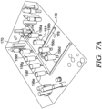
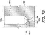
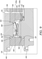
- a gas counter pressure (GCP) system may affect a pressure within the mold cavity during the molding process (e.g., prior to distribution of the SPS into the cavity; dwell of SPS in the mold cavity; foaming of SPS in the mold cavity; etc.).
- the GCP system may include one or more vents in the mold cavity that allow pressurized gas to pass into or from the mold cavity, and in one aspect, a property of the one or more vents (e.g., size, location, etc.) may relate to a viscosity of the SPS. For example, with a lower viscosity SPS, a size of the one or more vents may be increased (relative to systems molding higher viscosity SPS), which may increase the efficiency of the GCP system.
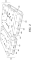
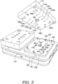
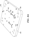
- the present disclosure describes a system of molds that may be used to manufacture a range of sizes of footwear articles.
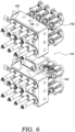
- the system of molds might include a first mold for a first sole size and a second mold for a second sole size (different from the first sole size), which each include a respective interface for fluidly communicating with a universal (shared) runner plate (e.g., a universal hot-runner plate or universal cold-runner plate affixed to injection nozzles).
- the interface of each of the first mold and the second mold may be constructed similarly (e.g., similar port size, shape, position, and number).
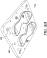
- the first mold may include a first set of runners and gates that communicate with the universal runner plate
- the second mold may include a second set of runners and gates that communicate with the universal runner plate.
- the first and second sets of runners and gates may be configured differently from one another (e.g., different runner paths/numbers and gate positions/numbers) in order to effectively distribute the SPS to a respective mold cavity having a respective size.
- Using a universal plate affixed to the injection nozzles, instead of a separate plate for each mold may, among other things, reduce costs associated with constructing and maintaining the tooling.
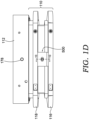
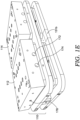
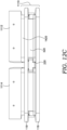
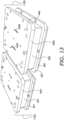
- the mold plates may include a series of pins and stops that permit the plates to be moved and spaced with respect to one another at different stages of the molding process, such as at the unloading station.
- the tooling may include carrier plates that permit the mold plates to be manipulated, transported, and properly aligned at different stages of the molding process.
- the tooling may include a latch assembly that releasably connects portions of the tooling together.
- thermoplastic polymer articles incorporating recycled thermoplastic materials
- methods for operating such systems methods for operating such systems, shoe structure segments fabricated from such articles, and footwear assembled with such segments.
- the present technology enables the waste from an injection molding operation (e.g., runner waste, flashing, reused foam, etc.) to be reincorporated/integrated into a subsequently formed midsole such that the net waste from the molding operation is greatly reduced and/or eliminated.
- an injection molding operation e.g., runner waste, flashing, reused foam, etc.
- thermoplastic such as a regrind thermoplastic polyester elastomer (TPE-E) composition.
- the midsole is a foam component with a foam volume, which includes a foam core and an integrally formed skin that encases the foam core.
- spent scrap and waste thermoplastic material such as foamed and/or unfoamed TPE-E composition
- spent scrap and waste thermoplastic material is ground into granular form and mixed into a composition containing virgin polymer.
- the mixture of ground/pelletized recycled material and virgin material is heated into a polymer melt composition, which is then passed, under pressure, through an injection barrel.
- a supercritical fluid such as supercritical nitrogen or supercritical carbon dioxide
- SPS molten single-phase solution
- the injection molding system foams and molds the ground virgin and recycled polymer using a microcellular molding process in which the SCF is employed as a physical blowing agent.
- the SPS may then be flowed into the mold cavity, at which point system conditions are modulated to activate transition of the SCF to a gas (e.g., nucleation to a gas) and the polymer to solidify.
- This transition of the polymer composition in the mold cavity may cause the polymer composition to expand (e.g., by foaming) to fill the mold cavity and, once solidified, retain the shape of the foam polymer product.
- the tooling and components of the injection molding system, as well as the calibrated parameters for operating the molding system may be specifically tailored to mold foamed polymer articles using recycled TPE-E composition.
- regrind and virgin polymer material may occur, as mentioned above, inside an injection barrel via a dry blend process; alternatively, regrind and virgin material recombination may occur on a separate extrusion line and, once combined, the pre-blended pellets may then be fed into the injection molder.
- a method for manufacturing foamed polymer articles from recycled TPE-E or TPE-E composition includes, in any order and in any combination with any of the above or below disclosed features and options: inputting a batch of recycled thermoplastic polyester elastomer composition; grinding the recyclate batch into a ground recyclate material; combining a metered amount of the ground recyclate material with ground or pelletized virgin thermoplastic polyester elastomer composition into a mixed batch, the metered amount being about 20% by mass or less of a total mass of the mixed batch; melting the mixed batch into a polymer melt composition; adding a physical foaming agent to the polymer melt composition; injecting the polymer melt composition with the physical foaming agent into an internal cavity of a mold tool; forming the foamed polymer article by activating the physical foaming agent such that the physical foaming agent causes the polymer melt composition to
- a method of manufacturing a foamed polymer article includes, in any order and in any combination with the above and/or below concepts: grinding a recyclate batch of recycled thermoplastic polyester elastomer composition into a ground recyclate material; combining a metered amount of the ground recyclate material and a virgin polymer material of virgin thermoplastic polyester elastomer composition into a mixed batch; melting the ground recyclate material and the virgin polymer material into a polymer melt composition; adding a physical foaming agent to the polymer melt composition; injecting the polymer melt composition with the physical foaming agent into an internal cavity of a mold tool; activating the physical foaming agent such that the physical foaming agent causes the polymer melt composition to expand and fill the internal cavity of the mold tool to form the foamed polymer article; and removing the formed foamed polymer article from the mold tool.
- a method of manufacturing a foamed polymer article includes, in any order and in any combination with the above and/or below concepts: adding a physical foaming agent to a polymer melt composition, the polymer melt composition including a blend of a recyclate polymer material and a virgin polymer material, both of virgin thermoplastic polyester elastomer compositions, the recyclate polymer material being about 20% by mass or less of a total mass of the polymer melt composition; injecting the polymer melt composition with the physical foaming agent into an internal cavity of a mold tool; activating the physical foaming agent such that the physical foaming agent causes the polymer melt composition to expand and fill the internal cavity of the mold tool to form the foamed polymer article; and removing the formed foamed polymer article from the mold tool.
- FIG. 1 For purposes of this disclosure, a method is presented for operating a manufacturing system to reduce waste during production of a foamed polymer article, such as a sole component of a shoe.
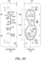
- This representative method includes, in any order and in any combination with any of the above or below disclosed features and options: injecting a mixed thermoplastic composition resin into a mold, the mixed thermoplastic composition resin including a mixture of virgin thermoplastic composition resin and recycled thermoplastic composition resin, and the mold comprising an internal mold cavity that is fluidly connected to one or more filling portions, such as a sprue, runner, and/or gate; and foaming the mixed thermoplastic composition resin within the internal mold cavity to form the foamed polymer article.
- the mass of the recycled thermoplastic composition resin within the internal mold cavity is greater than or equal to a mass of the mixed thermoplastic composition resin within the filling portion of the mold.
- a method of reducing waste during production of a foamed sole component of a shoe includes, in any order and in any combination with any of the above or below disclosed features and options: injecting a mixed thermoplastic composition resin into a mold, the mixed thermoplastic composition resin comprising a mixture of a virgin thermoplastic composition resin and a recycled thermoplastic composition resin, and the mold comprising a sole cavity portion fluidly coupled to a filling portion; and foaming the mixed thermoplastic composition resin within the sole cavity portion to form the foamed sole component of the shoe, wherein a mass of the recycled thermoplastic composition resin within the sole cavity portion is greater than or equal to a mass of the mixed thermoplastic composition resin within the filling portion.
- an article of footwear such as an athletic shoe, includes an upper that receives and attaches to the user's foot.
- a single-piece or multilayered sole structure which is attached to a lower portion of the upper, supports thereon the user's foot.
- This sole structure includes an outsole that defines the ground-engaging portion of the footwear.
- the sole structure is fabricated with one or more foamed sole components, each of which includes a metered amount of a (ground or pelletized) recycled thermoplastic polyester elastomer composition and a (ground or pelletized) virgin thermoplastic polyester elastomer composition.
- the metered amount of recyclate TPE-E composition is about 20% by mass or less of a total mass of the mixed batch.
- the method includes: grinding a recyclate batch of recycled thermoplastic polyester elastomer composition into a ground recyclate material; combining a metered amount of the ground recyclate material and a virgin polymer material of virgin thermoplastic polyester elastomer composition into a mixed batch; prior to or after combining, melting the ground recyclate material and the virgin polymer material into a polymer melt composition; adding a physical foaming agent to the polymer melt composition; injecting the polymer melt composition with the physical foaming agent into an internal cavity of a mold tool; activating the physical foaming agent such that the physical foaming agent causes the polymer melt composition to expand and fill the internal cavity of the mold tool to form the foamed polymer article; and removing the formed foamed polymer article from the mold tool.
- the formed foamed polymer article has: a ratio of energy efficiency to energy intensity that is greater than about 1.3; a ratio of energy efficiency to the product of energy intensity and density that is greater than about 5.9; a ratio of energy return to energy intensity that is greater than about 7,225; and/or a ratio of energy return to the product of energy intensity and density that is greater than about 38,250.
- the method includes: injecting a mixed thermoplastic composition resin into a mold, the mixed thermoplastic composition resin comprising a mixture of a virgin thermoplastic composition resin and a recycled thermoplastic composition resin; and foaming the mixed thermoplastic composition resin within an internal mold cavity of a molding system to form the foamed polymer article, wherein a mass of the recycled thermoplastic composition resin within the mixed thermoplastic composition resin is at least about 20% by mass of a total mass of the mixed thermoplastic composition resin.
- the recycled TPE-E composition in the recyclate batch includes scrap material or waste material, or both, that was recovered from an un-foamed batch of extruded TPE-E composition and/or a foamed batch of injection molded TPE-E composition.
- the recycled and virgin TPE-E compositions may be derived from a dihydroxy-terminated polydiol material, such as a poly(alkylene oxide)diol, or a C2-C8 diol material, such as an ethanediol, propanediol, butanediol, pentanediol, or an aromatic dicarboxylic acid material, such as a C5-C16 dicarboxylic acid, or any combination thereof.
- the physical foaming agent may be added by injecting the physical foaming agent into the polymer melt composition while the polymer melt composition is contained in an injection barrel of an injection molding system.
- the physical foaming agent may be an SCF, such as supercritical nitrogen and/or supercritical carbon dioxide.
- the mixed batch of ground recyclate material and virgin polymer material may have a set point temperature of at least about 150 °C or, in some embodiments, ranging from about 190 °C to about 265 °C.
- the mixed batch of recyclate and virgin materials may have an average peak crystallization temperature of at least about 90 °C or, in some embodiments, ranging from about 135 °C to about 165 °C.
- a resultant foamed polymer article may have a cell size average, e.g., by volume of a longest cell dimension, of less than about 0.68 mm or, in some embodiments, about 0.18 mm to about 0.58 mm.
- Creating the polymer melt composition may comprise melting then mixing the recyclate and virgin materials or melting a mixed batch already containing the recyclate and virgin materials.
- the resultant foamed polymer article exhibits: a ratio of energy efficiency to energy intensity that is between about 1.1 and about 1.9; a ratio of energy efficiency to the product of energy intensity and density that is between about 4.8 and about 9.1; a ratio of energy return to energy intensity that is between about 6,000 and about 11,000; and/or a ratio of energy return to the product of energy intensity and density that is greater than about 45,000.
- the recycled and virgin thermoplastic polyester elastomer compositions may be derived from a block copolymer, a segmented copolymer, a random copolymer, and/or condensation copolymer, and may have a weight average molecular weight (Mw) of at least about 30,000 Daltons or, in some embodiments, about 50,000 Daltons to about 200,000 Daltons.
- Mw weight average molecular weight
- the ground recyclate material may be processed prior to melting the mixed batch.
- This processing may include adding a filler, pigment, and/or processing aid to the ground recyclate material (before or after incorporation into the mixed batch).
- adding the physical foaming agent to the polymer melt composition may include dissolving a supercritical inert fluid into the polymer melt composition under pressure to form a single-phase solution.
- activating the physical foaming agent may include releasing the pressure to expand the supercritical inert fluid.
- Receiving the recyclate batch of recycled TPE-E composition may include obtaining, from a sprue, a runner, and/or a gate of an injection molding system, scrap segments of a prior-foamed polymer article formed from a prior mixed batch of ground recyclate material and virgin polymer material.
- a resultant foamed article formed with recycled polymer material may have an energy return measurement that is within a predefined tolerance of an energy return measurement of a comparable foamed article formed entirely or almost entirely from virgin polymer material.
- the predefined tolerance of a foamed sole component formed with recyclate is about 75% to about 99% of the energy return measurement of a comparable shoe sole component formed from virgin material.
- a shoe sole component may be considered "comparable" to another sole component if the two articles share an equivalent or nearly equivalent common shape, size, and/or method of molding.
- a percent by mass of the recycled thermoplastic resin within the mixed thermoplastic resin may be less than about 30% or, in some embodiments, between about 1% and about 20%.
- the filling portion of the mold comprises one or more cold runners.
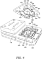
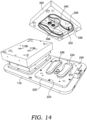
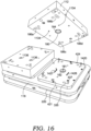
- the filling portion may include one or more hot runners disposed within one or more runner plates, which may be stacked on and fluidly coupled to one or more mold plates that define therein the internal mold cavity.
- the filling portion may consist of one or more channels that direct a flow of mixed thermoplastic resin from a nozzle or hot runner of an injection molding apparatus to the internal mold cavity portion of the mold.
- the ground recyclate material may have an irregular shape with a largest measurement of about 1-10mm, and the virgin polymer material has a pellet size of about 1-10mm.
- a foamed sole component may have a melting temperature of at least about 190 °C and an average peak crystallization temperature of at least about 135 °C.
- thermoplastic elastomer foam i.e., a foam formed by expanding a thermoplastic elastomer composition as disclosed herein
- thermoplastic polyester foams can exhibit various beneficial properties.
- the thermoplastic elastomer foam can exhibit a beneficial split tear, for example a high split tear value for a sole component in an article of footwear.
- the thermoplastic elastomer foam can have a split tear value of greater than about 1.5 kilogram/centimeter (kg/cm), or greater than about 2.0 kg/cm, or greater than about 2.5 kg/cm, when determined using the Split Tear Test Method described herein.
- the thermoplastic elastomer foam can have a split tear value of 1.0 kg/cm to 4.5 kg/cm, or 1.0 kg/cm to 4.0 kg/cm, or 1.5 kg/cm to 4.0 kg/cm, or 2.0 kg/cm to 3.5 kg/cm, or 2.5 kg/cm to 3.5 kg/cm, when determined using the Split Tear Test method described herein.
- the thermoplastic elastomer foam can have a split tear value of 0.8 kg/cm to 4.0 kg/cm, or 0.9 kg/cm to 3.0 kg/cm, or 1.0 to 3.0 kg/cm, or of 1.0 kg/cm to 2.5 kg/cm, or 1 kg/cm to 2 kg/cm.
- the thermoplastic elastomer foam is injection molded, and has a split tear value of 0.7 kg/cm to 2.5 kg/cm, or 0.8 kg/cm to 2.0 kg/cm, or 0.9 to 1.5 kg/cm, or 1.0 kg/cm to 2.5 kg/cm, or of 1.0 kg/cm to 2.2 kg/cm.
- the thermoplastic elastomer foam can have an open-cell foam structure.
- the thermoplastic elastomer foam can be the product of physically foaming a thermoplastic elastomer composition as disclosed herein, i.e., a foam formed using a physical foaming agent (i.e., a physical blowing agent).
- thermoplastic elastomer foam is understood to refer to a foamed material which has thermoplastic and elastomeric properties.
- the thermoplastic elastomer foam can be the foamed product of foaming a thermoplastic elastomer composition comprising less than 10 weight percent, or less than 5 weight percent, or less than 1 weight percent of non-polymeric ingredients based on a total weight of the thermoplastic elastomer composition.
- the thermoplastic elastomer foam is injection molded (i.e., is not exposed to a separate compression molding step after being formed by injection molding and removed from the injection mold).
- the thermoplastic elastomer foam is injection molded and subsequently compression molded in a separate compression mold having different dimensions than the mold used in the injection molding step.
- the density or specific gravity of a disclosed thermoplastic elastomer foam is also an important physical property to consider when using a foam for an article of apparel, footwear or athletic equipment.
- the thermoplastic elastomer foam of the present disclosure exhibits a low density or specific gravity, which beneficially reduces the weight of midsoles or other components containing the thermoplastic elastomer foam.
- thermoplastic elastomer foams of the present disclosure can have a specific gravity of from 0.02 to 0.22, or 0.03 to 0.12, or 0.04 to 0.10, or 0.11 to 0.12, or 0.10 to 0.12, or 0.15 to 0.20, or 0.15 to 0.30, when determined using the Specific Gravity Test Method described herein.
- the thermoplastic elastomer foams can have a specific gravity of from 0.15 to 0.22, such as from 0.17 to 0.22 or from 0.18 to 0.21, when determined using the Specific Gravity Test Method described herein.
- the thermoplastic elastomer foam can have a specific gravity of from 0.01 to 0.10, or 0.02 to 0.08, or 0.03 to 0.06, or 0.08 to 0.15, or 0.10 to 0.12, when determined using the Specific Gravity Test Method described herein.
- the specific gravity of the thermoplastic elastomer foam can be from 0.15 to 0.2, or 0.10 to 0.12.
- the thermoplastic elastomer foam can be injection molded, or can be injection molded and subsequently compression molded.
- the thermoplastic elastomer foam has a specific gravity of about 0.7 or less, or 0.5 or less, or 0.4 or less, or 0.3 or less, when determined using the Specific Gravity Test Method described herein.
- the thermoplastic elastomer foam including the thermoplastic elastomer foam present in midsoles and midsole components, can have a specific gravity of 0.05 to 0.25, or 0.05 to 0.2, or 0.05 to 0.15, or 0.08 to 0.15, or 0.08 to 0.20, or 0.08 to 0.25, or 0.1 to 0.15, when determined using the Specific Gravity Test Method described herein.
- the thermoplastic elastomer foam has a specific gravity of about 0.15 to about 0.3, or about 0.2 to about 0.35, or about 0.15 to about 0.25, when determined using the Specific Gravity Test Method described herein.
- the thermoplastic elastomer foam article or article component can be formed by injection molding without a subsequent compression molding step.
- the thermoplastic elastomer foam can have an open-cell foam structure.
- the thermoplastic elastomer foam can be the foamed product of foaming a thermoplastic elastomer composition comprising less than 10 weight percent, or less than 5 weight percent, or less than 1 weight percent of non-polymeric ingredients based on a total weight of the thermoplastic elastomer composition.
- thermoplastic elastomer foams of the present disclosure can have a density of from 0.02 grams per cubic centimeter (g/cc) to 0.22 g/cc, or 0.03 g/cc to 0.12 g/cc, or 0.04 g/cc to 0.10 g/cc, or 0.11 g/cc to 0.12 g/cc, or 0.10 g/cc to 0.12 g/cc, or 0.15 g/cc to 0.2 g/cc, or 0.15 g/cc to 0.30 g/cc, when determined using the Density Test Method described herein.
- thermoplastic elastomer foams can have a density of from 0.15 g/cc to 0.22 g/cc, such as from 0.17 g/cc to 0.22 g/cc, or from 0.18 g/cc to 0.21 g/cc, when determined using the Density Test Method described herein.
- the thermoplastic elastomer foam can have a density of from 0.01 g/cc to 0.10 g/cc, or 0.02 g/cc to 0.08 g/cc, or 0.03 g/cc to 0.06 g/cc, or 0.08 g/cc to 0.15 g/cc, or 0.10 g/cc to 0.12 g/cc, when determined using the Density Test Method described herein.
- the density of the thermoplastic elastomer foam can be from 0.15 g/cc to 0.2 g/cc, or 0.10 g/cc to 0.12 g/cc.
- thermoplastic elastomer foam can be injection molded, or can be injection molded and subsequently compression molded.
- the thermoplastic elastomer foam has a density of about 0.7 g/cc or less, or 0.5 g/cc or less, or 0.4 g/cc or less, or 0.3 g/cc or less, or 0.2 g/cc or less, when determined using the Density Test Method described herein.
- the thermoplastic elastomer foam can have a density of 0.05 g/cc to 0.25 g/cc, or 0.05 g/cc to 0.2 g/cc, or 0.05 g/cc to 0.15 g/cc, or 0.08 g/cc to 0.15 g/cc, or 0.08 g/cc to 0.20 g/cc, or 0.08 g/cc to 0.25 g/cc, or 0.10 g/cc to 0.15 g/cc, when determined using the Density Test Method described herein.
- thermoplastic elastomer foam has a density of about 0.15 g/cc to about 0.30 g/cc, or about 0.20 g/cc to about 0.35 g/cc, or about 0.15 g/cc to about 0.25 g/cc, when determined using the Density Test Method described herein.
- the thermoplastic elastomer foam article or article component can be formed by injection molding without a subsequent compression molding step.
- the thermoplastic elastomer foam can have an open-cell foam structure.
- thermoplastic elastomer foam can be the foamed product of foaming a thermoplastic elastomer composition comprising less than 10 weight percent, or less than 5 weight percent, or less than 1 weight percent of non-polymeric ingredients based on a total weight of the thermoplastic elastomer composition.
- thermoplastic elastomer foam portion of the article or component of an article, including thermoplastic polyester foam portion can have a stiffness of about 200 kPa to about 1000 kPa, or about 300 to about 900 kPa, or about 400 to about 800 kPa, or about 500 to about 700 kPa, when determined using the Cyclic Compression Test for a Sample with a 45 millimeter diameter cylindrical sample.
- the thermoplastic elastomer foam portion of the article or component of an article can have a stiffness of about 100 N/mm to about 400 N/mm, or about 150 N/mm to about 350 N/mm, or about 200 N/mm to about 300 N/mm, or about 225 N/mm to about 275 N/mm, when determined using the Cyclic Compression Test for a Foot Form with the foot form sample.
- the thermoplastic elastomer foam article or article component can be formed by injection molding without a subsequent compression molding step.
- the thermoplastic elastomer foam can have an open-cell foam structure.
- thermoplastic elastomer foam can be the foamed product of foaming a thermoplastic elastomer composition comprising less than 10 weight percent, or less than 5 weight percent, or less than 1 weight percent of non-polymeric ingredients based on a total weight of the thermoplastic elastomer composition.
- thermoplastic elastomer foam portion of the article or component of an article can have an Asker C durometer hardness of from about 30 to about 50, or from about 35 to about 45, or from about 30 to about 45, or from about 30 to about 40, when determined using the Durometer Hardness Test described herein.
- the thermoplastic elastomer foam article or article component can be formed by injection molding without a subsequent compression molding step.
- the thermoplastic elastomer foam can have an open-cell foam structure.
- thermoplastic elastomer foam can be the foamed product of foaming a thermoplastic elastomer composition comprising less than 10 weight percent, or less than 5 weight percent, or less than 1 weight percent of non-polymeric ingredients based on a total weight of the thermoplastic elastomer composition.
- the energy input of a foam is the integral of the force displacement curve during loading of the foam during the Cyclic Compression test.
- the energy return of a foam is the integral of the force displacement curve during unloading of the foam during the Cyclic Compression test.
- the thermoplastic elastomer foam portion of the article or component of an article, including a thermoplastic polyester foam portion can have an energy return of about 200 millijoules (mJ) to about 1200 mJ, or from about 400 mJ to about 1000 mJ, or from about 600 mJ to about 800 mJ, when determined using the Cyclic Compression Test for a Sample with a 45 millimeter diameter cylindrical sample.
- the thermoplastic elastomer foam portion of the article or component of an article can have an energy input of about 2000 millijoules (mJ) to about 9000 mJ, or from about 3000 mJ to about 8000 mJ, or from about 4500 mJ to about 6500 mJ, when determined using the Cyclic Compression Test for a Foot Form with the foot form sample.
- the thermoplastic elastomer foam article or article component can be formed by injection molding without a subsequent compression molding step.
- the thermoplastic elastomer foam can have an open-cell foam structure.
- thermoplastic elastomer foam can be the foamed product of foaming a thermoplastic elastomer composition comprising less than 10 weight percent, or less than 5 weight percent, or less than 1 weight percent of non-polymeric ingredients based on a total weight of the thermoplastic elastomer composition.
- the energy efficiency (EE) a measure of the percentage of energy of the thermoplastic elastomer foam portion of the article or component, including a thermoplastic polyester foam portion, returns when it is released after being compressed under load, which can provide improved performance for athletic footwear, e.g., for reducing energy loss or dissipation when running. This is especially true for running and other athletic footwear.
- the thermoplastic elastomer foam portion of the articles and components provided herein have an energy efficiency of at least 50 percent, or at least 60 percent, or at least 70 percent, or at least about 75 percent, or at least about 80 percent, or at least about 85 percent, when determined using the Cyclic Compression Test for a Sample with a 45 millimeter diameter cylindrical sample.
- thermoplastic elastomer foam portion of the articles and components provided herein can have an energy efficiency of at about 50 percent to about 97 percent, or about 60 percent to about 95 percent, or about 60 percent to about 90 percent, or about 60 percent to about 85 percent, or about 65 percent to about 85 percent, or about 70 percent to about 85 percent, or about 70 percent to about 90 percent, or about 70 percent to about 95 percent, when determined using the Cyclic Compression Test for a Sample with a 45 millimeter diameter cylindrical sample.
- the thermoplastic elastomer foam article or article component can be formed by injection molding without a subsequent compression molding step.
- the thermoplastic elastomer foam can have an open-cell foam structure.
- thermoplastic elastomer foam can be the foamed product of foaming a thermoplastic elastomer composition comprising less than 10 weight percent, or less than 5 weight percent, or less than 1 weight percent of non-polymeric ingredients based on a total weight of the thermoplastic elastomer composition.
- the resulting foams can have a multicellular closed-cell or open-cell foam structure.
- Cells are the hollow structures formed during the foaming process, in which bubbles are formed in the thermoplastic elastomeric composition by the foaming agents.
- the cell walls are generally defined by the thermoplastic elastomeric composition.
- “Closed cells” form an individual volume that is fully enclosed and that is not in fluid communication with an adjoining individual volume.
- Closed-cell structures” refer to foam structures in which at least 50 percent or more of the cells are closed cells, or at least 60 percent or more of the cells are closed cells, or at least 80 percent of the cells are closed cells, or at least 90 percent of the cells are closed cells, or at least 95 percent of the cells are closed cells.
- Open-cell structures refer to foam structures in which less than 50 percent, or less than 40 percent, or less than 20 percent, or less than 10 percent, or less than 5 percent or less than 4 percent, or less than 3 percent or less than 1 percent of the cells are closed cells.
- open-cell and closed-cell thermoplastic elastomer foams may have an average cell size (e.g., maximum width or length) linearly measured from one side of the cell to an opposing side of the cell.
- open-cell and closed-cell thermoplastic elastomer foams may have an average cell size of from about 50 micrometers to about 1000 micrometers, or from about 80 micrometers to about 800 micrometers, or from about 100 micrometers to about 500 micrometers.
- open-cell and closed-cell thermoplastic elastomer foams may form all or a portion of a non-footwear article, and in those instances, the foams may have a cell diameter including these example cell sizes, smaller than these example cell sizes, larger than these example cell sizes, or any combination thereof.
- the proportion of cells in the thermoplastic elastomer foam having a cell diameter of about 50 micrometers to about 1000 micrometers is preferably not less than 40 percent relative to all the cells, or not less than 50 percent or not less than 60 percent relative to all the cells. If the proportion of cells is less than 40 percent, the cell structure will tend to be nonuniform and/or have a coarse cell structure.
- a "coarse cell structure” refers to a foam structure in which the average cell diameter is greater than 1 millimeter, and/or for greater than 20 percent of the cells, a 1 millimeter line drawn across the largest dimension of the cell, will not cross a cell wall or a strut (i.e., an open cell wall or portion thereof).
- the number of open cells and/or closed cells and cell diameter of the cells of the foam can be determined visually, for example by capturing an image of a cut surface with a camera or digital microscope, determining the number of cells, number of open cells and/or number of closed cells, and determining an area of a cell, and converting it to the equivalent circle diameter.
- the disclosed foamed thermoplastic elastomer compositions can be prepared by various methods as disclosed herein and as known in the art. That is, disclosed articles or components of articles such as midsoles, midsole components, inserts and insert components can be prepared by injection molding a melt composition comprising a thermoplastic elastomer composition as described herein using a physical foaming agent, using a combination of a physical foaming agent and a chemical foaming agent, or using only a chemical foaming agent.
- a disclosed foam component e.g., a disclosed foam article or component, can be prepared by the methods disclosed herein below.
- forming a mixture of a molten thermoplastic elastomer composition and a foaming agent comprising: forming a mixture of a molten thermoplastic elastomer composition and a foaming agent; injecting the mixture into a mold cavity; foaming the thermoplastic elastomer composition, thereby forming a foamed thermoplastic elastomer composition; solidifying the foamed thermoplastic elastomer composition, thereby forming a foam article having a multicellular foam structure; and removing the foam article from the mold cavity.
- forming the mixture of the thermoplastic elastomer composition and the foaming agent comprises forming a single-phase solution of a liquid, gas or supercritical fluid foaming agent and the molten thermoplastic elastomer composition.
- the mixture is a single-phase solution of supercritical nitrogen or supercritical carbon dioxide and the thermoplastic elastomer composition.
- the mixture is a single-phase solution of supercritical nitrogen in a thermoplastic polyester composition.
- the thermoplastic elastomer composition comprises less than 10 weight percent, or less than 5 weight percent, or less than 1 weight percent of non-polymeric ingredients based on a total weight of the thermoplastic elastomer composition.
- injecting the mixture into a mold cavity can comprise injecting the single-phase solution into a mold cavity, then cooling the single-phase solution in the mold cavity prior to decreasing pressure in the mold cavity to a level at which the supercritical fluid phase transitions to a gas, and the gas drops out of solution in the molten polymer, forming gas bubbles in the molten polymer and foaming the molten polymer.
- the foaming forms a foam having an open-cell foam structure.
- Also disclosed are methods for making a foam article or component the method comprising: forming a mixture of a molten thermoplastic elastomer composition and a foaming agent; injecting the mixture into a mold cavity; foaming the molten thermoplastic elastomer composition in the mold cavity, thereby forming a thermoplastic elastomer foam; solidifying the thermoplastic elastomer foam in the mold cavity, thereby forming a molded foam article comprising a thermoplastic elastomer composition having a multicellular foam structure; and removing the molded foam article from the mold cavity.
- the temperature of the mixture at the point that it is foamed in the mold cavity is from about the melting temperature of the thermoplastic elastomer composition to about 50 degrees C above the tail temperature of the thermoplastic elastomer composition.
- the melting temperature of the thermoplastic elastomer composition is the melting temperature of a polymeric component of the thermoplastic elastomer composition. In other aspects, the melting temperature of the thermoplastic elastomer composition is the melting temperature of a thermoplastic elastomer present in the thermoplastic elastomer composition.
- the melting temperature of the thermoplastic elastomer present in the thermoplastic elastomer composition is the melting temperature of the thermoplastic elastomer having the highest melting temperature of all polymers present in the polymeric component of the thermoplastic elastomer composition.
- the melting temperature is the melting temperature of a thermoplastic polyester, such as a polyester elastomer, present in the thermoplastic elastomer composition.
- the foaming can occur when the mixture is at a foaming temperature, wherein the foaming temperature is a temperature from about the melting temperature of the thermoplastic elastomer to about 50 degrees C above the tail temperature of the thermoplastic elastomer.
- thermoplastic elastomer composition comprises forming a single-phase solution of a supercritical fluid and the molten thermoplastic elastomer composition.
- the thermoplastic elastomer composition can comprise less than 10 weight percent, or less than 5 weight percent, or less than 1 weight percent of non-polymeric ingredients based on a total weight of the thermoplastic elastomer composition. If more than one thermoplastic elastomer is present in the thermoplastic elastomer composition, the melting temperature can be the highest melting temperature of the thermoplastic elastomers present in the composition.
- injecting the mixture into a mold cavity can comprise injecting the single-phase solution into a mold cavity, then cooling the single-phase solution in the mold cavity prior to decreasing pressure in the mold cavity to a level at which the supercritical fluid phase transitions to a gas, and the gas drops out of solution in the thermoplastic elastomer composition, forming gas bubbles in the thermoplastic elastomer composition and foaming the thermoplastic elastomer.
- the foaming can form a foam having an open-cell foam structure.
- DSC Dynamic scanning calorimetry
- 10 - 30 mg pieces of undried resin pellets are cycled from -90 degrees C to 225 degrees C at 20 degrees C /min and cooled to - 90 degrees C at 10 degrees C/min.
- experiments are run using a heat-cool-heat profile with a ramp rate of 10 degrees C per min, minimum temperature of 0 degrees C and maximum temperature of 250 degrees C. Analyses should be determined in duplicate.
- the melting temperature and glass transition temperature values are recorded from the second cycle.
- the melt "peak” is identified as the local maximum of the second heating cycle. If there is more than one peak in the DSC curve, the peak occurring at hotter temperatures is chosen as the temperature reference.
- the tail is identified as the intersection of the tangent of the line of the higher temperature side of the melt peak with the extrapolated baseline.
- the disclosed foamed thermoplastic elastomer compositions can be prepared using a suitable injector.
- the injector can have a motor to turn a screw inside the injector.
- the injector may include a single screw or twin screws, and may include individual elements of various sizes and pitches appropriate for mixing or kneading the specific materials used.
- the various components included in the foamed thermoplastic elastomer compositions described herein can be added into the injector through one or more ports.
- the various components can be added as a melt or as appropriately-sized solid particles, for example chips or pellets, which may be melted as they are mixed in the barrel of the injector.
- the contents of the injector can be heated to melt the composition.
- a physical foaming agent such as, for example, a supercritical fluid can be added into the melt while it is present in the barrel of the injector.
- thermoplastic polyester foam is prepared by using a physical foaming agent which foams the composition in the mold cavity, and the resulting thermoplastic elastomer foam is thus substantially free of unreacted chemical blowing agents or a decomposition or degradation product of a chemical blowing agent.
- the thermoplastic elastomer composition can be added to the injector as a melt at a temperature close to the melting temperature of the polymeric component of the composition.
- the processing (melting) temperature used can be sufficiently below the temperature that would trigger the chemical foaming agent.
- the temperature near the exit of the injector or within the mold cavity can be increased to a temperature close to or at the triggering temperature of the chemical foaming agent, thereby producing a chemically foamed thermoplastic polyester foam as the composition exits the injector (e.g., as the composition is injected into a mold cavity), or within the mold cavity.
- the temperature of the runners leading to the mold cavity or the mold cavity or both can be a temperature at or above the triggering temperature of the chemical foaming agent, thereby producing a chemically foamed thermoplastic elastomer foam within the runners and/or the mold cavity.
- a physical foaming agent can be used to foam the thermoplastic elastomer composition to form a physically foamed thermoplastic elastomer foam, or a physically and chemically foamed thermoplastic elastomer foam.
- a supercritical fluid such as supercritical carbon dioxide or supercritical nitrogen can be mixed with the molten thermoplastic elastomer composition in the barrel of the injector to form a single-phase solution.
- a pressure drop can be used to cause the supercritical fluid to transition to the gas phase and foam the thermoplastic elastomer composition.
- a gas counter-pressure can be applied to the mold cavity and to the runners leading to the mold cavity.
- the counter pressure can be a pressure sufficiently high to keep the supercritical fluid in solution within the runners and the mold cavity. Once a dose of the single-phase solution is in the mold cavity, the counter-pressure within the mold cavity can be decreased to a level at which the supercritical fluid phase transitions to a gas and drops out of solution in the molten thermoplastic elastomer composition, forming gas bubbles in the thermoplastic elastomer composition and foaming the thermoplastic elastomer composition in the mold cavity.
- the thermoplastic elastomer composition comprises less than 10 weight percent, or less than 5 weight percent, or less than 1 weight percent of non-polymeric ingredients based on a total weight of the thermoplastic elastomer composition, and the multicellular foam has an open-cell structure.
- the articles, cushioning elements, or components of articles such as midsoles, midsole components, inserts and insert components can be prepared by injection molding a thermoplastic elastomer composition described herein using a physical foaming agent.
- the injection molding process can use a screw-type injector that allows for maintaining and controlling the pressure in the injector barrel.
- the injection molding machine can allow metering and delivering a supercritical fluid such as carbon dioxide or nitrogen into the thermoplastic elastomer composition prior to injection.
- the supercritical fluid can be mixed into the thermoplastic elastomer composition within the injection barrel and then injected into the mold cavity.
- the injection molding process can include physical foaming of the compositions described herein using an injection molding process which forms a multicellular foam structure, such as, for example the "MUCELL” process (Trexel Inc., Wilmington, Massachusetts, USA).
- thermoplastic elastomer foams described herein can be made using a process that involves impregnating a thermoplastic elastomer composition (e.g., at or above a softening temperature of the composition) with a physical foaming agent at a first concentration or first pressure.
- a thermoplastic elastomer composition e.g., at or above a softening temperature of the composition
- a physical foaming agent at a first concentration or first pressure.
- the term "impregnating” generally means dissolving or suspending a physical foaming agent in a composition.
- the impregnated composition can then be foamed, or can be cooled (when applicable) and re-softened (when applicable) for foaming at a later time.
- the impregnated molten thermoplastic elastomer composition forms a single-phase solution comprising a supercritical fluid (e.g., carbon dioxide or nitrogen) dissolved in the molten thermoplastic elastomer composition.
- a supercritical fluid e.g., carbon dioxide or nitrogen
- the thermoplastic elastomer composition comprises less than 10 weight percent, or less than 5 weight percent, or less than 1 weight percent of non-polymeric ingredients based on a total weight of the thermoplastic elastomer composition.
- the impregnated thermoplastic elastomer composition (e.g., the single-phase solution) is foamed by reducing the solubility of the physical foaming agent in the thermoplastic elastomer composition through pressure and/or temperature changes.
- the pressure and/or temperature change can occur immediately after the impregnated composition exits the injector or the injection barrel, or can occur in the runners leading to the mold cavity, or can occur in the mold cavity.
- the system can include hot runners or gas counter-pressure or both, which control the temperature and pressure under which the impregnated composition is held, up to and including the point at which the composition enters the mold cavity.
- the temperature and pressure under which the impregnated composition is held are controlled such that the impregnated composition remains a single-phase solution up to and including the point it enters the mold cavity.
- the temperature or the pressure or both can be altered to reduce the solubility of the supercritical fluid in the molten thermoplastic elastomer composition, causing the molten thermoplastic elastomer composition to expand into a foam, including a foam having an open-cell foam structure.
- the reduction in solubility of the physical foaming agent can release additional amounts of gas (e.g., to create a secondary expansion of a partially-foamed thermoplastic elastomer composition), to further expand the composition, forming a foam structure (e.g., a foam having a multicellular structure).
- a chemical blowing agent can be activated in the thermoplastic elastomer composition in the mold cavity to create a secondary expansion of a partially-foamed thermoplastic elastomer composition.
- Chemical foaming agents may be endothermic or exothermic, which refers to a type of decomposition or degradation they undergo to produce the gas used to produce the foam.
- the decomposition or degradation may be triggered by thermal energy present in the molding system.
- Endothermic foaming agents absorb energy and typically release a gas, such as carbon dioxide, upon decomposition.
- Exothermic foaming agents release energy and generate a gas, such as nitrogen, when decomposed.
- thermal variables of the thermoplastic elastomer composition being foamed and thermal variables of the foaming agent to be decomposed or degraded are coupled together such that process parameters are selected so that the thermoplastic elastomer composition can be foamed and molded and the foaming agent can decompose or degrade at an appropriate phase of the foaming and molding process.
- Thermoplastic elastomer compositions disclosed herein include one or more thermoplastic elastomers.
- the one or more thermoplastic elastomers can be one or more thermoplastic polyester elastomers.
- the thermoplastic elastomer composition includes at least 90 percent, or at least 95 weight percent, or at least 99 weight percent of a thermoplastic resin component, based on the total weight of the thermoplastic elastomer composition, where thermoplastic resin component includes all the polymers present in the composition.
- Thermoplastic resin component comprises one or more thermoplastic elastomers.
- Thermoplastic resin component can comprise at least one thermoplastic polyester elastomer.
- Thermoplastic resin component can comprise more than one thermoplastic polyester elastomer.
- Thermoplastic resin component can comprise one or more thermoplastic polyester elastomer, and one or more thermoplastic polyester which is not an elastomer.
- thermoplastic resin component comprises the one or more thermoplastic polyester, and further comprises one or more thermoplastic polymers each of which is not a polyester.
- the one or more thermoplastic polymers each of which is not a polyester can each be a thermoplastic elastomer.
- thermoplastic resin component consists essentially of the one or more thermoplastic elastomer.
- thermoplastic resin component can consist essentially of one or more thermoplastic polyester elastomer.
- the thermoplastic elastomer composition comprises less than 10 weight percent, or less than 5 weight percent, or less than 1 weight percent of non-polymeric ingredients based on the total weight of the thermoplastic elastomer composition.
- the thermoplastic elastomer composition is substantially free of non-polymeric nucleating agents, or is substantially free of non-polymeric fillers, or is substantially free of coloring agents, or is substantially free of non-polymeric processing aids, or is substantially free of both non-polymeric nucleating agents and non-polymeric fillers, or is substantially free of non-polymeric nucleating agents, non-polymeric fillers, coloring agents, and non-polymeric processing aids.
- the thermoplastic elastomer composition comprises less than 10 weight percent, or less than 5 weight percent, or less than 1 weight percent of solid coloring agents, based on the total weight of the thermoplastic elastomer composition.
- the thermoplastic elastomer composition consists essentially of one or more thermoplastic elastomers.
- the thermoplastic elastomer composition consists essentially of one or more thermoplastic polyester elastomers.
- a thermoplastic polyester elastomer can refer to a thermoplastic polyester homopolymer elastomer, a thermoplastic copolyester elastomer, or both.
- the thermoplastic copolyester elastomer can include copolyesters having two or more types of polyester monomeric segments, or copolyesters comprising polyester monomeric segments and one or more non-polyester monomeric segments.
- the resin component of the thermoplastic elastomer composition which is comprised of all the polymeric materials present in thermoplastic polyester composition, consists essentially of the one or more thermoplastic elastomers, or consists essentially of the one or more thermoplastic polyesters.
- Thermoplastic polyesters can include chain units derived from one or more olefins and chain units derived from one or more ethylenically-unsaturated acid groups, in aspects.
- the thermoplastic elastomer compositions can have a melt flow index of from about 5 to about 40, or about 10 to about 20, or about 20 to about 30 as determined at 210 degrees C using a 2.16 kilogram weight.
- the thermoplastic elastomer compositions can have a melt flow index of from about 5 to about 40, or about 10 about 20, or about 20 to about 30 as determined at 220 degrees C using a 2.16 kilogram weight.
- the thermoplastic elastomer compositions can have a melt flow index of from about 5 to about 40, or about 10 to about 20, or about 20 to about 30 as determined at 230 degrees C using a 2.16 kilogram weight.
- thermoplastic elastomer including thermoplastic polyester, can have a weight average molecular weight of about 50,000 Daltons to about 1,000,000 Daltons; or about 50,000 Daltons to about 500,000 Daltons; or about 75,000 Daltons to about 300,000 Daltons; or about 100,000 Daltons to about 250,000 Daltons; or about 100,000 Daltons to about 500,000 Daltons.
- thermoplastic elastomers can be terpolymers.
- thermoplastic copolyesters can be terpolymers of moieties derived from ethylene, acrylic acid, and methyl acrylate or butyl acrylate.
- a ratio of a total parts by weight of the acrylic acid in thermoplastic copolyesters to a total weight of thermoplastic copolyesters is about 0.05 to about 0.6, or about 0.1 to about 0.6, or about 0.1 to about 0.5, or about 0.15 to about 0.5, or about 0.2 to about 0.5.
- thermoplastic elastomers can be terpolymers comprising a plurality of first segments, a plurality of second segments, and a plurality of third segments.
- the thermoplastic elastomer is a thermoplastic copolyester comprising: (a) a plurality of first segments, each first segment derived from a dihydroxy-terminated polydiol; (b) a plurality of second segments, each second segment derived from a diol; and (c) a plurality of third segments, each third segment derived from an aromatic dicarboxylic acid.
- thermoplastic copolyester is a block copolymer.
- thermoplastic copolyester is a segmented copolymer.
- thermoplastic copolyester is a random copolymer.
- thermoplastic copolyester is a condensation copolymer.
- the thermoplastic elastomer including thermoplastic copolyester, can have a ratio of first segments to third segments from about 1:1 to about 1:5 based on the weight of each of the first segments and the third segments; or about 1:1 to about 1:4 based on the weight of each of the first segments and the third segments; or about 1:1 to about 1:2 based on the weight of each of the first segments and the third segments; or about 1:1 to about 1:3 based on the weight of each of the first segments and the third segments.
- thermoplastic elastomer including thermoplastic copolyester
- the thermoplastic elastomer can have a ratio of second segments to third segments from about 1:1 to about 1:2 based on the weight of each of the first segments and the third segments; or about 1:1 to about 1:1.52 based on the weight of each of the first segments and the third segment.
- thermoplastic elastomer including thermoplastic copolyester
- the thermoplastic elastomer can have first segments derived from a poly(alkylene oxide)diol having a number-average molecular weight of about 250 Daltons to about 6000 Daltons; or about 400 Daltons to about 6,000 Daltons; or about 350 Daltons to about 5,000 Daltons; or about 500 Daltons to about 3,000 Daltons; or about 2,000 Daltons to about 3,000 Daltons.
- thermoplastic elastomer including thermoplastic copolyester
- first segments derived from a poly(alkylene oxide)diol such as poly(ethylene ether)diol; polypropylene ether)diol; poly(tetramethylene ether)diol; poly(pentamethylene ether)diol; poly(hexamethylene ether)diol; poly(heptamethylene ether)diol; poly(octamethylene ether)diol; poly(nonamethylene ether)diol; poly(decamethylene ether)diol; or mixtures thereof.
- a poly(alkylene oxide)diol such as poly(ethylene ether)diol; polypropylene ether)diol; poly(tetramethylene ether)diol; poly(pentamethylene ether)diol; poly(hexamethylene ether)diol; poly(heptamethylene
- thermoplastic copolyester can have first segments derived from a poly(alkylene oxide)diol such as poly(ethylene ether)diol; polypropylene ether)diol; poly(tetramethylene ether)diol; poly(pentamethylene ether)diol; poly(hexamethylene ether)diol.
- thermoplastic copolyester can have first segments derived from a poly(tetramethylene ether)diol.
- the thermoplastic elastomer can have second segments derived from a diol having a molecular weight of less than about 250.
- the diol from which the second segments are derived can be a C2-C8 diol.
- the second segments can be derived from ethanediol; propanediol; butanediol; pentanediol; 2-methyl propanediol; 2,2-dimethyl propanediol; hexanediol; 1,2- dihydroxy cyclohexane; 1,3- dihydroxy cyclohexane; 1,4- dihydroxy cyclohexane; and mixtures thereof.
- the second segments can be derived from 1,2-ethanediol, 1,3-propanediol, 1,4-butanediol, 1,6-hexanediol, and mixtures thereof.
- the second segments can be derived from 1,2-ethanediol.
- the second segments can be derived from 1,4-butanediol.
- the thermoplastic elastomer including the copolyester, can have third segments derived from an aromatic C5-C16 dicarboxylic acid.
- the aromatic C5-C16 dicarboxylic acid can have a molecular weight less than about 300 Daltons; about 120 Daltons to about 200 Daltons; or a value or values of molecular weight within any of the foregoing ranges or a molecular weight range encompassing any sub-range of the foregoing ranges.
- the aromatic C5-C16 dicarboxylic acid is terephthalic acid, phthalic acid, isophthalic acid, or a derivative thereof.
- the aromatic C5-C16 dicarboxylic acid is a diester derivative of the terephthalic acid, phthalic acid, or isophthalic acid. In a yet further aspect, the aromatic C5-C16 dicarboxylic acid is terephthalic acid or the dimethyl ester derivative thereof.
- Thermoplastic copolyester can comprise: (a) a plurality of first copolyester units, each first copolyester unit of the plurality comprising the first segment derived from a dihydroxy-terminated polydiol and the third segment derived from an aromatic dicarboxylic acid, wherein the first copolyester unit has a structure represented by a Formula 1: wherein R 1 is a group remaining after removal of terminal hydroxyl groups from the poly(alkylene oxide) diol of the first segment, wherein the poly(alkylene oxide) diol of the first segment is a poly(alkylene oxide) diol having a number-average molecular weight of about 400 to about 6000; and wherein R 2 is a group remaining after removal of carboxyl groups from the aromatic dicarboxylic acid of the third segment; and (b) a plurality of second copolyester units, each second copolyester unit of the plurality comprising the second segment derived from a diol and
- Thermoplastic copolyester can comprise a plurality of first copolyester units having a structure represented by a Formula 3: wherein R is H or methyl; wherein y is an integer having a value from 1 to 10; wherein z is an integer having a value from 2 to 60; and wherein a weight average molecular weight of each of the plurality of first copolyester units is from about 300 Daltons to about 7,000 Daltons.
- y can be an integer having a value of 1, 2, 3, 4, 5, 6, 7, 8, 9, 10; or y can be any set or range of the foregoing integer values.
- z is an integer having a value from 5 to 60; an integer having a value from 5 to 50; an integer having a value from 5 to 40; an integer having a value from 4 to 30; an integer having a value from 4 to 20; an integer having a value from 2 to 10; or z can be any set or range of the foregoing integer values.
- R is hydrogen.
- R is methyl.
- R is hydrogen and y is an integer having a value of 1, 2, or 3.
- R is methyl and y is an integer having a value of 1.
- Thermoplastic copolyester can comprise a plurality of first copolyester units having a structure represented by a Formula 4: wherein z is an integer having a value from 2 to 60; and wherein a weight average molecular weight of each of the plurality of first copolyester units is from about 300 Daltons to about 7,000 Daltons.
- y can be an integer having a value of 1, 2, 3, 4, 5, 6, 7, 8, 9, 10; or y can be any set or range of the foregoing integer values.
- z is an integer having a value from 5 to 60; or an integer having a value from 5 to 50; or an integer having a value from 5 to 40; or an integer having a value from 4 to 30; or an integer having a value from 4 to 20; or an integer having a value from 2 to 10.
- Thermoplastic copolyester can comprise a plurality of first copolyester units having a weight average molecular weight from about 400 Daltons to about 6,000 Daltons; or about 400 Daltons to about 5,000 Daltons; or about 400 Daltons to about 4,000 Daltons; or about 400 Daltons to about 3,000 Daltons; or about 500 Daltons to about 6,000 Daltons; or about 500 Daltons to about 5,000 Daltons; or about 500 Daltons to about 4,000 Daltons; or about 500 Daltons to about 3,000 Daltons; or about 600 Daltons to about 6,000 Daltons; or about 600 Daltons to about 5,000 Daltons; or about 600 Daltons to about 5,000 Daltons; or about 600 Daltons to about 4,000 Daltons; or about 600 Daltons to about 3,000 Daltons; or about 2,000 Daltons to about 3,000 Daltons.
- Thermoplastic copolyester can comprise a plurality of second copolyester units, each second copolyester unit of the plurality having a structure represented by a Formula 5: wherein x is an integer having a value from 1 to 20; wherein the foam article has a multicellular closed-cell or open-cell foam structure.
- x is an integer having a value from 2 to 18; 2 to 17; 2 to 16; 2 to 15; 2 to 14; 2 to 13; 2 to 12; 2 to 11; 2 to 10; 2 to 9; 2 to 8; 2 to 7; 2 to 6; 2 to 5; 2 to 4; or x can be any integer value or set of integer values within the foregoing ranges or values, or any range of integer values encompassing a sub-range of the foregoing integer value ranges.
- x is an integer having a value of 2, 3, or 4.
- Thermoplastic copolyester can comprise a plurality of second copolyester units, each second copolyester unit of the plurality having a structure represented by a Formula 6:
- Thermoplastic copolyester can comprise a weight percent range of the plurality of first copolyester units based on total weight of thermoplastic copolyester such that the weight percent range is about 30 weight percent to about 80 weight percent; or about 40 weight percent to about 80 weight percent; or about 50 weight percent to about 80 weight percent; or about 30 weight percent to about 70 weight percent; or about 40 weight percent to about 70 weight percent; or about 50 weight percent to about 70 weight percent; or about 40 weight percent to about 65 weight percent; or about 45 weight percent to about 65 weight percent; or about 50 weight percent to about 65 weight; or about 55 weight percent to about 65 weight percent; or about 40 weight percent to about 60 weight percent; or about 45 weight percent to about 60 weight percent; or about 50 weight percent to about 60 weight percent; or about 55 weight percent to about 60 weight percent.
- thermoplastic elastomer including thermoplastic copolyester
- the thermoplastic elastomer can comprise phase separated domains.
- a plurality of first segments derived from a dihydroxy-terminated polydiol can phase-separate into domains comprising primarily the first segments.
- a plurality of second segments derived from a diol can phase-separate into domains comprising primarily the second segments.
- thermoplastic copolyester can comprise phase-separated domains comprising primarily of a plurality of first copolyester units, each first copolyester unit of the plurality comprising the first segment derived from a dihydroxy-terminated polydiol and the third segment derived from an aromatic dicarboxylic acid, wherein the first copolyester unit has a structure represented by a Formula 1: wherein R 1 is a group remaining after removal of terminal hydroxyl groups from the poly(alkylene oxide) diol of the first segment, wherein the poly(alkylene oxide) diol of the first segment is a poly(alkylene oxide) diol having a number-average molecular weight of about 400 to about 6000; and wherein R 2 is a group remaining after removal of carboxyl groups from the aromatic dicarboxylic acid of the third segment; and other phase-separated domains comprising primarily of a plurality of second copolyester units, each second copolyest
- thermoplastic copolyester can comprise phase-separated domains comprising primarily of a plurality of first copolyester units, each first copolyester unit of the plurality having a structure represented by a Formula 3: wherein R is H or methyl; wherein y is an integer having a value from 1 to 10; wherein z is an integer having a value from 2 to 60; and wherein a weight average molecular weight of each of the plurality of first copolyester units is from about 300 Daltons to about 7,000 Daltons.
- y can be an integer having a value of 1, 2, 3, 4, 5, 6, 7, 8, 9, 10; or y can be any set or range of the foregoing integer values.
- z is an integer having a value from 5 to 60; an integer having a value from 5 to 50; an integer having a value from 5 to 40; an integer having a value from 4 to 30; an integer having a value from 4 to 20; an integer having a value from 2 to 10; or z can be any set or range of the foregoing integer values.
- R is hydrogen.
- R is methyl.
- R is hydrogen and y is an integer having a value of 1, 2, or 3.
- R is methyl and y is an integer having a value of 1.
- thermoplastic copolyester can comprise phase-separated domains comprising primarily of a plurality of first copolyester units, each first copolyester unit of the plurality having a structure represented by a Formula 4: wherein z is an integer having a value from 2 to 60; and wherein a weight average molecular weight of each of the plurality of first copolyester units is from about 300 Daltons to about 7,000 Daltons.
- y can be an integer having a value of 1, 2, 3, 4, 5, 6, 7, 8, 9, 10; or y can be any set or range of the foregoing integer values.
- z is an integer having a value from 5 to 60; or an integer having a value from 5 to 50; or an integer having a value from 5 to 40; or an integer having a value from 4 to 30; or an integer having a value from 4 to 20; or an integer having a value from 2 to 10.
- Thermoplastic copolyester can comprise phase-separated domains comprising primarily of a plurality of first copolyester units having a weight average molecular weight from about 400 Daltons to about 6,000 Daltons; or about 400 Daltons to about 5,000 Daltons; or about 400 Daltons to about 4,000 Daltons; or about 400 Daltons to about 3,000 Daltons; or about 500 Daltons to about 6,000 Daltons; or about 500 Daltons to about 5,000 Daltons; or about 500 Daltons to about 4,000 Daltons; or about 500 Daltons to about 3,000 Daltons; or about 600 Daltons to about 6,000 Daltons; or about 600 Daltons to about 5,000 Daltons; or about 600 Daltons to about 5,000 Daltons; or about 600 Daltons to about 4,000 Daltons; or about 600 Daltons to about 3,000 Daltons; or about 2,000 Daltons to about 3,000 Daltons
- thermoplastic copolyester can comprise phase-separated domains comprising a plurality of second copolyester units, each second copolyester unit of the plurality having a structure represented by a Formula 5: wherein x is an integer having a value from 1 to 20; wherein the foam article has a multicellular closed-cell or open-cell foam structure.
- x is an integer having a value from 2 to 18; or 2 to 17; or 2 to 16; or 2 to 15; or 2 to 14; or 2 to 13; or 2 to 12; or 2 to 11; or 2 to 10; or 2 to 9; or 2 to 8; or 2 to 7; or 2 to 6; or 2 to 5; or 2 to 4.
- thermoplastic copolyester can comprise phase-separated domains comprising a plurality of second copolyester units, each second copolyester unit of the plurality having a structure represented by a Formula 6:
- Thermoplastic copolyester can comprise phase-separated domains comprising a weight percent range of the plurality of first copolyester units based on total weight of thermoplastic copolyester such that the weight percent range is about 30 weight percent to about 80 weight percent; or about 40 weight percent to about 80 weight percent; or about 50 weight percent to about 80 weight percent; or about 30 weight percent to about 70 weight percent; or about 40 weight percent to about 70 weight percent; or about 50 weight percent to about 70 weight percent; or about 40 weight percent to about 65 weight percent; or about 45 weight percent to about 65 weight percent; or about 50 weight percent to about 65 weight percent; or about 55 weight percent to about 65 weight percent; or about 40 weight percent to about 60 weight percent; or about 45 weight percent to about 60 weight percent; or about 50 weight percent to about 60 weight percent; or about 55 weight percent to about 60 weight percent.
- thermoplastic elastomer composition can include one or more thermoplastic polyester homopolymer, where the thermoplastic polyester homopolymer comprises any of the polyester monomeric segments or units disclosed herein or modifications thereof.
- thermoplastic elastomer composition can include one or more thermoplastic polyester homopolymer, where the thermoplastic polyester homopolymer comprises any polyester homopolymer exhibiting any or all of the properties and parameters discussed herein with respect to thermoplastic elastomers and/or the thermoplastic elastomer composition.
- thermoplastic elastomer composition the polymeric component of the composition or an individual thermoplastic elastomer in neat form can be characterized by one or more properties.
- the thermoplastic elastomer composition or the polymeric component, or the polymer has a maximum load of about 10 newtons to about 100 newtons, or from about 15 newtons to about 50 newtons, or from about 20 newtons to about 40 newtons, when determined using the Cyclic Tensile Test method described herein.
- the tensile strength of the thermoplastic elastomer composition or of the polymeric component of the thermoplastic elastomer composition or of a thermoplastic elastomer in neat form is another important physical characteristic.
- the thermoplastic elastomer composition or polymeric component or elastomer can have a tensile strength of from 5 kilograms per square centimeter to 25 kilograms per square centimeter, or of from 10 kilograms per square centimeter to 23 kilograms per square centimeter, or of from 15 kilograms per square centimeter to 22 kilograms per square centimeter, when determined using the Cyclic Tensile Test method described herein.
- thermoplastic elastomer composition or polymeric component of the thermoplastic elastomer composition or a thermoplastic elastomer in neat form can have a tensile modulus of about 2 megapascals to about 20 megapascals or from about 5 megapascals to about 15 megapascals when determined using the Cyclic Tensile Test method described herein.
- thermoplastic elastomers including thermoplastic polyesters, that can be used in the disclosed methods, foams, and articles include “HYTREL” 3078, “HYTREL” 4068, and “HYTREL” 4556 (DuPont, Wilmington, Delaware, USA); “PELPRENE” P30B, P40B, and P40H (Toyobo U.S.A.
- thermoplastic elastomer compositions can further include one or more thermoplastic polyurethanes, such as "FORTIMO” (Mitsui Chemicals, Inc., Tokyo, Japan); “TEXIN” (Covestro LLC, Pittsburgh, Pennsylvania, USA); and “BOUNCELL-X” (Lubrizol Advanced Materials, Inc., Brecksville, Ohio, USA).
- thermoplastic polyurethanes such as "FORTIMO” (Mitsui Chemicals, Inc., Tokyo, Japan); “TEXIN” (Covestro LLC, Pittsburgh, Pennsylvania, USA); and “BOUNCELL-X” (Lubrizol Advanced Materials, Inc., Brecksville, Ohio, USA).
- the disclosed thermoplastic elastomer compositions can further include one or more olefinic polymers.
- Olefinic polymers can include ethylene-based copolymers, propylene-based copolymers, and butene-based copolymers.
- the olefinic polymer is an ethylene-based copolymer such as a styrene-ethylene/butylene-styrene (SEBS) copolymer; an ethylene-propylene diene monomer (EPDM) copolymer; an ethylene-vinyl acetate (EVA) copolymer; an ethylene alkyl acrylate (EAA) copolymer; an ethylene alkyl methacrylate (EAMA) copolymer; any copolymer thereof, and any blend thereof.
- SEBS styrene-ethylene/butylene-styrene
- EPDM ethylene-propylene diene monomer
- EVA ethylene-vinyl a
- a ratio V of a total parts by weight of the olefinic polymers present in the composition to a total parts by weight of thermoplastic polyesters in the composition is about 0.0 to about 0.6, or about 0.0 to about 0.4, or about 0.01 to about 0.4, or about 0.01 to about 0.6, or about 0.1 to about 0.4.
- the disclosed thermoplastic elastomer compositions can further include an ethylene-vinyl acetate (EVA) copolymer.
- EVA ethylene-vinyl acetate
- the ethylene-vinyl acetate (EVA) copolymer can have a range of vinyl acetate contents, for example about 50 percent to about 90 percent, or about 50 percent to about 80 percent, or about 5 percent to about 50 percent, or about 10 percent to about 45 percent, or about 10 percent to about 30 percent, or about 30 percent to about 45 percent, or about 20 percent to about 35 percent, based on the weight of the copolymer.
- This procedure can be used to obtain a sample of a foam composition or material when the composition or material is incorporated into a component such as a sole structure or midsole or outsole of an article of footwear.
- a sample of the component which includes the composition or material is obtained as formed into the component, or cut from the article of footwear using a blade.
- This process is performed by separating the component from an associated footwear upper, if present, and removing any materials from the article's top surface (e.g., corresponding to the top surface).
- the article's top surface can be skinned, abraded, scraped, or otherwise cleaned to remove any upper adhesives, yarns, fibers, foams, and the like that could potentially interfere with the test results.
- the resulting component sample includes the composition or material.
- any test using a Component Sampling Procedure can simulate how the composition or material will perform as part of an article of footwear.
- the component may be tested as a full component (e.g., full midsole component), or it can be extracted as a sample having a certain geometry.
- a sample of a component is taken at a location along the component that provides a substantially constant thickness for the component (within plus or minus 10 percent of the average thickness), such as in a forefoot region, mid-foot region, or a heel region of the article.
- the desired harvested geometry is a cylindrical puck with a 45-millimeter diameter and a cylinder height of at least about 10 millimeters, preferably from about 20 to 25 millimeters.
- the density is measured for samples taken using the Component Sampling Procedure, using a digital balance or a Densicom Tester (Qualitest, Plantation, Florida, USA). For each sample a sample volume is determined in cubic centimeters, and then each sample is weighed (g). The density of the sample is the mass divided by the sample volume, given in grams/cubic centimeters.
- Force/displacement behavior for the foams and the foamed articles may be measured using a full midsole sample, a full outsole sample, a split midsole and/or a split midsole, tested using a foot form for impact to accurately simulate full gate loading.
- a US men's size 10 midsole is tested, and a men's size 9 foot form used for impact, with a load of 2000N being applied to the midsole with the foot form at a loading rate of 5 Hz with a cyclic compression testing device such an Instron Electropuls E10000 (Instron, Norwood, Massachusetts, USA). Each sample is compressed to the peak load at 5Hz for 100 cycles.
- Energy input (J), energy return(J), energy efficiency (energy return/energy input), energy efficiency percentage (100*(energy return/energy input)) and maximum displacement (mm) are measured from the force vs. displacement curves generated. Stiffness of a particular foam sample is the maximum load divided by the displacement at the maximum load, giving a value in N/mm. The reported value for each metric is the average of the metrics from the 60 th , 70 th , 80 th , and 90 th cycles.
- Force/displacement behavior for the foams and the foamed articles may also, or alternatively, be measured using samples harvested from a larger component (e.g., cylindrical pucks harvested from a footwear midsole), and a method for obtaining a sample is described in the "Component Sampling Procedure" portion of this disclosure.
- a sample e.g., a cylindrical puck harvested from a larger component
- the sample is tested along the length axis of the part using compression platens that are at least 2x the diameter (e.g., of the cylindrical puck).
- the sample is compressed to the peak load (e.g., 50% strain) at 5Hz for 500 cycles. Stiffness, efficiency, and energy return are measured from the force vs.
- Stiffness, efficiency, and energy return are defined in the following ways, with example property ranges (possibly dependent on sample geometries) provided in parentheses. Stiffness is the stress at the maximum strain divided by the maximum strain (e.g., 200 - 1000 kPa). Efficiency is the integral of the unloading force-displacement curve divided by the integral of the loading force-displacement curve (e.g., 0.50 - 0.97). Energy return is the integral of the unloading curve (e.g., 200-1200 mJ).
- the cyclic tensile testing is carried out on solid samples prepared using the Component Sampling Procedure, having a dog-bone shape as described in ASTM D638 with a 2 mm thickness.
- the specimen is placed under a pre-load of 5 N. Strain is controlled to extend the sample to an extension 6 percent at a strain rate of 5 Hz. The stiffness is the load at 6 percent strain divided by the extension at 6 percent strain, giving a value in N/mm. The maximum load (N) observed over the test cycle of 500 cycles is also recorded.
- the test used to obtain the hardness values for the foam articles is as follows.
- a flat foam sample is prepared using the Component Sampling Procedure, where the sample has a minimum of 6 mm thick for Shore A durometer testing. If necessary, samples are stacked to make up the minimum thickness. Samples are large enough to allow all measurements to be performed at a minimum of 12 mm from the edge of the sample and at least 12 mm from any other measurement. Regions tested are flat and parallel with an area at least 6 mm in diameter. A minimum of five hardness measurements are taken and tested using a 1 kilogram head weight.
- the split tear test can determine the internal tear strength for a foam material.
- a sample may be provided using the Component Sampling Procedure. The sample is die cut into a rectangular shape having a width of 1.54 centimeters and a length of 15.24 centimeters (1 inch by 6 inches), and having a thickness of 10 millimeters, plus or minus 1 millimeter. On one end, a cut is made into the sample that bisects the thickness, the cut extending the full width of the sample, and 3 centimeters from the end of the sample. Starting from the end of the cut, 5 marks are placed along the length of the sample spaced 2 centimeters apart. The cut ends of the sample are placed in the clamps of a tensile tester.
- Each section of the sample is held in a clamp in such a manner that the original adjacent cut edges form a straight line joining the centers of the clamps.
- the crosshead speed is set to 50 millimeters per minute.
- the tear strength is measured throughout the separation of the crossheads. If necessary, a sharp knife may be used to keep separating the foam in the center of the sample, discarding the readings caused by cutting of the knife.
- the lowest split tear strength values are recorded for each of the five marked segments of the sample (between each of the 2-centimeter markings). An average split tear strength value is recorded for each sample. If a segment of a sample has an air bubble measuring more than 2 millimeters, the tear strength for the segment is discarded, and the air bubble recorded as a test defect. If more than one segment of a sample has an air bubble measuring more than 2 millimeters, the entire sample is discarded.
- Energy intensity is a measure of the energy used in forming a particular foam article in kilowatt hours (kW-h).
- the energy required (in kW-H) to produce a run, or batch, of articles, such as cushioning elements (such as pairs of the midsole 122) is first calculated, determined or measured (from pellet to finished component).
- the measured energy may include the energy required for all energy consuming steps, such as: preheating the molds and hot runners (if utilized), melting the pellets, generating gas counter-pressure, injecting the molten plastic, introducing the supercritical fluid, cooling the molds and/or work-pieces and ejecting the work-pieces from the mold.
- the overall energy required to produce the run of cushioning element pairs is then divided by the number of cushioning element pairs produced in the run.
- the zero shear viscosity is determined using a flow curve obtained on a rotational rheometer.
- Zero shear viscosity is determined as the apparent viscosity of the polymer melt measured at a shear rate of 1 ⁇ 10 -2 1/s when the polymer is heated to 10°C above its melting temperature.
- Apparent viscosity is measured under continuous flow using a cone and plate rotational fixture. The temperature of the rotational fixture is maintained at the polymer melt temperature. The gap and geometry of the cone are selected such that the measured torque is well within the measuring limits of a rheometer.
- the melt flow index is determined using a sample prepared using Component Sampling Procedure, according to the test method detailed in ASTM D1238-13 Standard Test Method for Melt Flow Rates of Thermoplastics by Extrusion Plastometer, using Procedure A described therein. Briefly, the melt flow index measures the rate of extrusion of thermoplastics through an orifice at a prescribed temperature and load. In the test method, approximately 7 grams of the sample is loaded into the barrel of the melt flow apparatus, which has been heated to a specified temperature of 210 degrees C, 220 degrees C, or 230 degrees C. A weight of 2.16 kilograms is applied to a plunger and the molten sample is forced through the die. A timed extrudate is collected and weighed. Melt flow rate values are calculated in g/10 min, and are reported with the specified temperature (i.e., 210, 220 or 230 degrees C) and the weight applied to the plunger ( i.e., 2.15 kilograms).
- a tooling assembly 110 is illustrated in combination with a first hot-runner plate 112 and a second hot-runner plate 114.
- the tooling assembly 110 includes one or more injection molds coupled to a first carrier plate 116 and a second carrier plate 118, which may support the one or more molds during one or more stages of an injection-molding process (e.g., when the molds are being transported from one station to another station, when the part(s) are being unloaded, etc.).
- an injection-molding system and components for forming an article comprising a foamed thermoplastic elastomer composition.
- FIG. 1A a tooling assembly 110 is illustrated in combination with a first hot-runner plate 112 and a second hot-runner plate 114.
- the tooling assembly 110 includes one or more injection molds coupled to a first carrier plate 116 and a second carrier plate 118, which may support the one or more molds during one or more stages of an injection-molding process (e.g., when the molds are being
- the hot-runner plates 112 and 114 and the carrier plates 116 and 118 have been omitted to unobstructedly illustrate a first mold 120 and a second mold 122.
- the first hot-runner plate 112 interfaces with the first mold 120
- the second hot-runner plate 114 interfaces with the second mold 122 to distribute one or more deposits or shots of thermoplastic elastomer composition (e.g., single-phase solution or other composition having a foaming agent) into mold cavities.
- thermoplastic elastomer composition e.g., single-phase solution or other composition having a foaming agent
- the first mold 120 includes a first mold plate 220, a mold ring plate 320, and a second mold plate 420
- the second mold 122 might also include a respective first mold plate 221, a respective mold ring plate 321, and a respective second mold plate 421 having similar elements.
- the first mold plate 220, the mold ring plate 320, and the second mold plate 420 are layerable (e.g., stackable) to form one or more cavities for receiving a deposit of a thermoplastic elastomer composition.
- FIG. 3 depicts a partially exploded view including the first mold plate 220 and the mold ring plate 320 separated from one another.
- a portion of a first mold cavity and a portion of a second mold cavity can be seen, each of which is shaped to form at least a portion of a footwear sole.
- the first mold 120 includes two mold cavities, in other aspects, a mold may include fewer or more mold cavities.
- the first mold cavity may be at least partially enclosed by a mold core 224, and the second mold cavity may include a similar mold core 226 (although a mirror image).
- the mold core 224 is nestable in a mold-ring cavity 328 when the mold ring plate 320 is layered against or abutting the first mold plate 220.
- FIG. 4 depicts a partially exploded view with the second mold plate 420 being separated from the mold ring plate 320.
- the second mold plate 420 may be positioned directly against (e.g., abutting) the mold ring plate 320 to more fully enclose the mold-ring cavity 328.
- the second mold plate 420 may also include one or more runners and gates through which the thermoplastic elastomer composition may flow when being deposited into the cavities. For example, FIG.
- FIG. 4 depicts a plurality of gate outlets 434, 436, 438, 440, 442 and 444
- FIG. 2 depicts a plurality of runner inlets 426, 428, 430, and 432 and runners that are fluidly coupled to the plurality of gate outlets 434, 436, 438, 440, 442 and 444.
- FIG. 5 a partially exploded view depicts the hot-runner plate 112 that interfaces with the second mold plate 420, and the hot-runner plate 112 may include one or more hot-runner outlets 134a-134h that align with, and fluidly connect to, the plurality of runner inlets 426, 428, 430, and 432 of the second mold plate 420.
- FIG. 1A depicts the hot-runner plate 112 interfacing with the second mold plate 420 and also depicts a plurality of nozzle-receiving openings 136a-136h into which injection nozzles may be inserted for distributing material through the hot-runner plate 112 and the second mold plate 420 and into the mold cavity or cavities.
- an example of a set of injection nozzles (e.g., 138) is shown as part of an injection manifold 140. That is, the injection manifold 140 includes an injection port 142 that connects to an injector of an injection molding system. The injection manifold 140 also includes a series of internal components (not shown) that receive a deposit/shot of thermoplastic elastomer composition from the injector and divide the shot into a number of deposits for separately distributing through the nozzles.
- the injection manifold 140 may also include one or more sensors (e.g., thermocouples) for monitoring conditions of the manifold (e.g., temperature, pressure, etc.) that may affect the thermoplastic elastomer composition, as well as a manifold temperature conditioning unit for maintaining, increasing, or decreasing a temperature of the manifold.
- the manifold temperature conditioning unit may include conditioned-fluid lines 150 for holding and transporting coolant or heated conditioning fluid.
- a state of the thermoplastic elastomer composition e.g., single-phase solution
- a deposit is distributed from each nozzle into the hot-runner plates 112 and 114.
- the manifold 140 may maintain the thermoplastic elastomer composition at conditions conducive to maintaining the foaming agent in a supercritical-fluid phase and to reducing the likelihood of transition to a gas.
- the manifold includes an injector-pin assembly (e.g., 152) for each nozzle, which may selectively insert a pin (or other obstruction) into a tip of each nozzle to impede a flow of material.
- the nozzles are arranged in groups of nozzles, including between two and six nozzles.
- the nozzles are arranged in four groups of four linearly aligned nozzles, and in other aspects the groups may include two, three, five, or six linearly aligned nozzles.
- Each group of nozzles is positioned to collectively inject material into a single mold cavity.
- each group of four nozzles is configured to inject material into a single mold cavity having a three-dimensional shape of a footwear component (e.g., footwear sole).
- four nozzles optimizes the available footprint and injection-system real estate operable to distribute material in to the mold cavity having the 3D shape of a footwear sole. That is, the 3D shape of an average size footwear sole includes a length and four nozzles may optimally use that length to evenly distribution shots of material into the mold cavity in a way that each shot foams and solidifies in a desired manner
- the manifold 140 includes sixteen nozzles, each of which is insertable into a respective nozzle-receiving opening (e.g., 136a-136h) of the hot-runner plates 112 and 114 depicted in FIG. 1A .
- a respective nozzle-receiving opening e.g., 136a-136h
- FIGs. 7A and 7B some of the walls of the hot-runner plate 112 are omitted to illustrate some interior components of the hot-runner plate 112 in more detail.
- the hot-runner plate 112 includes eight nozzle-receiving sleeves 156a-156h, each of which receives a respective nozzle of the injection manifold 140.
- Each nozzle-receiving sleeve includes a nozzle-receiving opening 136a-136h (see FIG. 1A and 136a in FIG. 7B ) and a sleeve outlet (e.g., 158 in the cross-sectional view of FIG. 7B ).
- the sleeve outlet 158 includes a perimeter rim 160 that forms a nozzle seat 162 against which a tip of the nozzle biases when then nozzle is fully inserted into the nozzle-receiving sleeve.
- the hot-runner plate 112 also includes hot runners (e.g., 164) that transport material from each nozzle after being dispensed.
- each hot runner e.g., 164 includes a hot-runner inlet (e.g., 166 in FIG. 7B ) that fluidly connects with the sleeve outlet (e.g., 158 in the cross-sectional view of FIG. 7B ) and includes a hot-runner outlet 134a-134h (see also FIG. 5 showing the hot-runner outlets).
- the hot-runner inlet is spaced apart from the hot-runner outlet by a distance in a range of about 1 cm to about 3 cm.
- this sprue length provides a grasping region at which a tool can grip the sprue for removing solidified material from the runners in the second mold plate 420.
- the hot-runner plate 112 includes various components to help control conditions related to the injection-molding system.
- the hot-runner plate 112 includes conditioned-fluid lines 170 for transporting conditioned fluid throughout the hot-runner plate 112.
- the conditioned fluid may be conditioned to include a temperature for maintaining, increasing, or decreasing a temperature of components of the hot-runner plate, including the hot runners (e.g., 164), the nozzle-receiving sleeves 156a-156h, and the nozzles when inserted in the sleeves (see also FIG. 1E depicting a conditioned-fluid inlet 172 and a conditioned fluid outlet 174 positioned on an exterior wall of the hot-runner plate 112).
- thermoplastic elastomer composition e.g., single-phase solution with supercritical fluid as physical foaming agent
- the temperature in the hot runner may be maintained high enough to delay transition of the supercritical fluid to a gas.
- the hot-runner plate 112 includes a gas conduit 176 having a first gas port 178 (see e.g., FIGs. 1A and 7A ) for fluidly communicating with a gas counter pressure (GCP) system and a second gas port 180 or "gas-conduit port" (see e.g., FIG. 5 ) for fluidly communicating with a gas port 181 (also referred to as "fluid-channel port") of the second mold plate 420.
- GCP gas counter pressure
- gas-conduit port see e.g., FIG. 5
- the side of the hot-runner plate 112 facing towards the mold includes a seal assembly for sealingly mating with the second mold plate 420.
- FIG. 5 depicts a seal groove 184 that receives a resilient seal 182.
- the second mold plate 420 may additionally, or alternatively, include a seal groove.
- the GCP system is fluidly connected from the gas port 178 on the hot-runner plate 112 to the sleeve outlet (e.g., 158 in FIG. 7B ).
- the sleeve outlet e.g., 158 in FIG. 7B .
- the hot-runner plate 112 is a universal hot-runner plate that is coupled directly to the manifold.
- one or more fasteners may couple the hot-runner plate 112 to the manifold 140.
- Some conventional injection molding systems may, in contrast to the present disclosure, have separate hot-runner plates that each interfaces with a different cold-runner plate (or other plate that is not temperature conditioned) and that are connected and disconnected to the manifold or nozzles in each injection cycle.
- This aspect of the present disclosure includes a universal hot-runner plate that is mountable to the nozzles and that can interface with an array of different molds, each of which includes a different mold cavity, a different gate scheme, or any combination thereof.
- the mold cavities may differ in volume and or shape as being used to mold parts of different sized shoes, and the gate scheme may differ by including different gate positions and/or quantities of gates.
- the hot-runner plate 112 is plumbed with all of the components used to control various aspects of the molding process, including the conditioned-fluid lines 170 and the gas conduit 176.
- Hot-runner plates are often associated with higher costs (e.g., added plumbing for temperature conditioning elements).
- a universal hot-runner plate may reduce costs across multiple sets of molds, since only a single, common hot-runner plate may be used across the multiple sets, as opposed to having to make a hot-runner plate for each mold.
- the first mold 120 includes the first mold plate 220, the mold ring plate 320, and the second mold plate 420.
- the second mold plate 420 includes a first side 422 that faces towards the mold ring plate 320 and a second side 424 that faces away from the mold ring plate 320.
- the first mold 120 interfaces with the hot-runner plate 112 (e.g., FIG. 1A )
- the second side 424 faces towards and abuts the hot-runner plate 112.
- the second side 424 includes a plurality of runner inlets 426, 428, 430, and 432 that align with, and receive material from, the hot-runner outlets of the hot-runner plate 112. Furthermore, each runner inlet may fluidly connect to one or more runners. For example, referring to FIG. 8C the runner inlet 426 fluidly connects with a first runner 426a and a second runner 426b, and the runner inlet 428 fluidly connects with a first runner 428a and a second runner 428b.
- the runner inlet 430 connects to a single runner, including a runner 430a, and the runner inlet 432 also connects to a single runner, including a runner 432a.
- FIG. 8C depicts the inlets of a plurality of secondary runners 427a, 427b, 429a, 429b, 431, and 433 that fluidly connect each runner to a respective gate and gate outlet of the second mold plate 420. That is, only the inlet of each secondary runner is viewable in FIG. 8C because the secondary runner extends from the second side 424, through a mold body of the second mold plate, towards the second side 422, the gates, and the gate outlets.
- the plurality of runner inlets 426, 428, 430, and 432 may include various features.
- each runner inlet is positioned and arranged to align with a hot-runner outlet 134d, 134c, 134b, and 134a (respectively) of the hot-runner plate 112.
- a hot-runner outlet 134d, 134c, 134b, and 134a (respectively) of the hot-runner plate 112.
- the material may flow into the runner inlets 426, 428, 430, and 432 to be directed to the mold cavity by way of the runners.
- the relative positioning of the runner inlets 426, 428, 430, and 432 represents a universal positioning and arrangement configured to align with the hot-runner outlets of the hot-runner plate. That is, in aspects in which the hot-runner plate 112 is a universal hot-runner plate used to interface with an array of different molds, each of the molds in the array may include a mold plate having runner inlets positioned similarly to the runner inlets 426, 428, 430, and 432, regardless of the arrangement of the runners. In one aspect, this universal positioning and arrangement includes four runner inlets that may be linearly aligned and that may be evenly spaced apart from one another. For example, FIG. 8C depicts a longitudinal reference line 435 marking a position of a longitudinal reference plane that intersects each of the runner inlets (the longitudinal reference plane extends orthogonal to the view shown in FIG. 8C at longitudinal reference line 435).
- the runners may also include various features.
- the runners may extend in various directions from a respective runner inlet to a secondary runner. That is, in some instances, a runner (e.g., 428a) may extend from a runner inlet in a direction aligned with the longitudinal reference plane, such that the secondary runner (e.g., 429a) and terminal gate outlet (e.g., 438) is also aligned with the longitudinal reference plane. In other examples, a runner (e.g., 428b) may extend from a runner inlet in a direction away from the longitudinal reference plane, and in this sense, the runner 428b is incongruent from the runner 428a.
- the runner (e.g., 428b) may curve or bend back into the longitudinal reference plane, such that the secondary runner (e.g., 429b) and terminal gate outlet is still aligned with the longitudinal reference plane.
- the runner (e.g., 426a, 426b, 430a, and 432a) may extend away from the longitudinal reference plane and terminate at a secondary runner (e.g., 427a, 427b, 431, and 433) not aligned with the longitudinal reference plane.
- the second mold plate 420 includes a mold cavity wall 425 on the first side 422 that encloses at least a portion of the mold cavity of the first mold 120.
- the mold cavity wall 425 includes a plurality of gate outlets through which material flows when injected into the mold cavity. That is, each secondary runner is fluidly connected with a respective gate outlet on the first side 422 of the second mold plate.
- FIG. 8C depicts a plurality of gate outlets 434, 436, 438, 440, 442, and 444 from which material may flow after being injected into the runners.
- each secondary runner tapers from a larger diameter near a respective runner to a smaller diameter near each gate.
- each gate outlet is an aperture having a diameter in a range of about 1.00 millimeters to about 5.00 millimeters, or 2.00 millimeters to 3.50 millimeters. In at least some instances, a diameter in this range is operable to affect a flow, condition, and/or foaming activity of a material injected through the gate outlet, and is related to a viscosity of the thermoplastic elastomer composition (e.g., single-phase solution).
- each gate outlet includes a position that is relative to other gate outlets and that is relative to the three-dimensional shape of the mold cavity.
- FIG. 8C depicts a longitudinal reference line 437 that is coplanar with the longitudinal reference line 435 (e.g., both being positioned in the same longitudinal reference plane) and that represents a position of the longitudinal reference plane.
- one or more gate outlets e.g., 438 and 440
- one or more gate outlets may be aligned with the longitudinal reference plane.
- one or more gate outlets e.g., 434, 436, 442, and 444 may be offset from the long longitudinal reference plane.
- a length of the mold cavity wall 425 may be evenly divided into a forefoot third 446, a midfoot third 448, and a heel third 450, and the gate outlets may be apportioned in various manners among the thirds.
- the heel third 450 includes three gate outlets 434, 436, and 438;
- the midfoot third 448 includes two gate outlets 440 and 442;
- the forefoot third includes a single gate outlet 444.
- this arrangement of gate outlets may contribute to dispersion and foaming of the thermoplastic elastomer composition in the mold cavity in a manner resulting in a foamed product having material properties conducive to a footwear sole.
- the gate outlets may be positioned in different arrangements.
- the variability of the runner orientations may permit runners to both include the universal runner inlet configuration and be positioned in a customized manner to mold a particular shape and/or size of foamed article.
- a mold configured to form a footwear sole for a first size (e.g., US men's size 10) footwear article may have a first set of runners
- a mold configured to form a footwear sole for a second size (e.g., US men's size 6) may have a second set of runners.
- Both the first set of runners and the second set of runners may each include a runner-inlet pattern matching the universal runner-inlet pattern depicted in FIG. 8C , and may also each include a different runner pattern configured to distribute material differently into a respective mold cavity based on the respective 3D mold-cavity shapes and sizes.
- One aspect of the present disclosure includes a mold system having a universal runner plate (e.g., universal hot-runner plate or universal cold-runner plate) and an array of two or more molds, each of which is configured to interface with the universal runner plate and includes a 3D mold-cavity size.
- the 3D mold-cavity size of a first mold of the array is for a footwear component of a first shoe size, such that the first mold includes a first runner configuration.
- the 3D mold-cavity size of the second mold of the array is for a footwear component of a second shoe size, such that the second mold includes a second runner configuration that is different from the first runner configuration (e.g., different positions of gate outlets).
- the first shoe size and the second shoe size are each in a range of US Men's 3.5 to US Men's 15, or US Men's 5 to US Men's 12, or US Men's 6 to US Men's 11, or US Men's 7 to US Men's 10.
- the first shoe size might be in a range of US Men's 3.5 to U.S. Men's 8, or US Men's 5 to US Men's 7.5, or US Men's 6 to US Men's 7; and the second shoe size might be in a range of US Men's 8.5 to US Men's 15, or US Men's 9 to US Men's 12, or US Men's 9 to US Men's 10.
- the second mold plate 420 includes a perimeter wall 452 forming a boundary along sides of the mold cavity wall 425.
- the mold ring plate 320 includes a mold cavity wall 322 at least partially enclosing the mold-ring cavity 328, and the mold cavity wall 322 includes a first perimeter ridge 324 traversing the perimeter of the mold-ring cavity 328.
- the perimeter wall 452 abuts the first perimeter ridge 324 to at least partially seal the mold cavity.
- FIG. 9 a cross-sectional view taken along the reference line 9-9 in FIG. 2 is provided, showing the first mold plate 220, the mold ring plate 320, and the second mold plate 420, assembled into the first mold 120 and enclosing a mold cavity C.
- FIG. 9 depicts the perimeter wall 452 abutting the first perimeter ridge 324.
- a seal assembly is positioned between the mold ring plate 320 and the second mold plate 420.
- a seal groove 326 may be positioned on a side 330 of the mold ring plate 320 facing towards the second mold plate 420 and a resilient seal may be positioned in the seal groove 326.
- a seal groove may also, or alternatively, be positioned on the first side 422 of the second mold plate 420.
- the first side 422 of the second mold plate 420 may include a gas port 454 that aligns with, and fluidly connects with, a gas port 332 of the mold ring plate 320, and this alignment and fluid connection is also depicted in the cross-sectional view of FIG. 9 .
- the second mold plate 420 may include a gas channel 458 fluidly connecting the gas port 181 on the second side 424 with the gas port 454 on the first side 422.
- the mold ring plate 320 includes at least a first pin-receiving aperture 334 (see e.g., FIG. 4 ) and the second mold plate includes at least a second pin-receiving aperture 456, which aligns with the first pin-receiving aperture 334 when the first mold 120 is assembled.
- the second pin-receiving aperture 456 is also shown in FIGs. 8A and 8B , including an opening on the first side 422, and an opening on the second side 424 - the opening on the second side including a width (e.g., diameter).
- the first pin-receiving aperture 334 may have a pin engager (e.g., threaded interior wall) to securely receive a pin (e.g., 335 depicted in FIG. 5 ) that is coupled in the first pin-receiving aperture 334 and that protrudes out of the first pin-receiving aperture 334 and into, or through, the second pin-receiving aperture 456.
- the pin 335 includes a head 337 or other stop on a portion of the pin 335 positioned on the second side 424 of the second mold plate 420.
- the hot-runner plate 112 may also have pin-receiving apertures 186a-186d into which a head of a pin (such as head 337 of pin 335) may be inserted when the mold interfaces with the hot-runner plate 112.
- the second mold plate 420 may be moved on the pin(s) away from the mold ring plate 320 to a pre-determined distance, based on a position of the head or stop on the pin (e.g., the length of the pin between the portion affixed to the mold ring plate 320 and the head).
- the second mold plate 420 may be moved away from the mold ring plate 320 along the pins in order to separate the molded part from the material in the gates and runners.
- the mold ring plate 320 includes a first side 338 that faces towards a second side 230 of the first mold plate 220, and the first side 338 is opposite a second side 330 ( FIG. 4 ) of the mold ring plate 320 facing towards the second mold plate 420.
- the mold cavity wall 322 of the mold ring plate 320 is depicted in FIG. 3 , together with a second perimeter ridge 340 traversing at least a portion of the perimeter of the mold cavity wall 322.
- the mold cavity wall 322 of the mold ring plate 320 may include the first perimeter ridge 324 and the second perimeter ridge 340, which divide the mold cavity wall 322 of the mold ring plate 320 into a first wall segment 323, a second wall segment 325, and a third wall segment 327 (see e.g., FIG. 9 ).
- the second wall segment 325 is between the first wall segment 323 and the third wall segment 327, and when the first mold 120 is assembled (see e.g., FIG. 9 ), the first wall segment 323 interfaces with the perimeter wall 452 of the second mold plate 420; the second wall segment 325 faces the mold cavity C; and the third wall segment 327 interfaces with the mold core 224.
- the mold core 224 nests inside the mold cavity wall 322 to at least partially enclose a portion of the mold-ring cavity 328.
- the mold core 224 is positioned adjacent the second perimeter ridge 340 to at least partially enclose the mold cavity.
- FIG. 9 a cross-sectional view is provided, showing the first mold plate 220, the mold ring plate 320, and the second mold plate 420, assembled into the first mold and enclosing a mold cavity C.
- FIG. 9 depicts the mold core 224 adjacent the second perimeter ridge 340, and the third wall segment 327 is spaced apart from the mold core 224.
- the mold core 224 is adjacent to, and spaced apart from, the second perimeter ridge 340 by a distance large enough to permit gas to flow through, and small enough to impede material flowing from the cavity.
- dashed circles 342 and 344 depict a location at which a perimeter edge of the mold core 224 (e.g., an edge at which the mold cavity wall formed by the mold core transitions to a side wall 231) and the second perimeter ridge 340 are slightly spaced apart to form a vent.
- the vent extends around at least a portion of the mold cavity C.
- the vent may extend around 50%, 60%, 70%, 80%, 90%, or 100% of the perimeter of the mold cavity C.
- the mold cavity C has a first cross-sectional profile as taken along a first plane that is perpendicular to an axis of the fluid channel 348, and the vent includes a second cross-sectional profile as taken along a second plane that is parallel to the first plane.
- FIG. 9 depicts a longitudinal reference line 235a marking a position of a first plane that is perpendicular to an axis of the fluid channel 348, and a longitudinal reference line 235b marking a position of a second plane parallel to the first plane (the first plane and the second plane extend orthogonal to the view shown in FIG. 9 at longitudinal reference lines 235a and 235b respectively).
- the first cross-sectional profile and the second cross-sectional profile may be substantially congruent.
- the distance between the perimeter edge of the mold core 224 and the second perimeter ridge 340 is in a range of about 0.5 millimeters to about 2.5 millimeters, or about 1.0 to about 2.0 millimeters.
- the vent identified by the dashed circles 342 and 344 fluidly connects with the open space between the third wall segment 327 and the side wall 231 of the mold core.
- the side wall 231 may form a first vent wall and the third wall segment 327 may form a second vent wall.
- the mold ring plate 320 includes a surface channel 346 in the first side 338 that extends from the third wall segment 327 (i.e., the second vent wall) to an internal gas channel 348, which extends entirely through a plate body of the mold ring plate and fluidly connects with the gas port 332.
- pressurized gas may be supplied from a GCP system connected to gas port 178 of the hot-runner plate 112, through the fluidly connected channels 458, 348, and 346 and through the vents, to the mold cavity C.
- the pressure of the gas may vary, and in one aspect, the pressure is in a range of about 550 psi to about 1500 psi.
- the positive pressure may further extend from the mold cavity C, through the runners of the second mold plate 420 and the hot-runner plate 112, and up to a nozzle tip.
- the pressurized gas may be actively pulled (e.g., via negative pressure or vacuum) from, or may passively flow from, the mold cavity C out of the gas port 178.
- this pressurized gas may help maintain a state of material flowed into the mold cavity and control a foaming activity.
- the runners and the mold cavity C may be pressurized prior to receiving shots of material, and the pressure may be maintained after the shots have been received in the cavity to effectuate a dwell time without the material foaming.
- the pressure may be released to trigger a phase transition, including a transition of the supercritical fluid to a gas.
- the dwell time includes a duration operable to bring a temperature of the thermoplastic elastomer composition in a range conducive to foaming a foam article having properties for a footwear article (e.g., sole).
- the first mold 120 may include features that contribute to controlling a temperature of the thermoplastic elastomer composition when dispersed into the mold cavity C.
- the first mold plate 220 may include a first side 229 (see FIG. 1B ) that is positionable on a cooling shelf or in a cooling rack to conductively lower a temperature of the first mold plate 220 (e.g., lower a temperature of the mold core 224 and resulting cavity wall that contact the thermoplastic elastomer composition when initially dispersed into the mold cavity).
- the first mold plate 220 may, in-turn, conductively lower a temperature of the mold ring plate 320, the second mold plate 420, the ambient or pressurized air in the mold cavity C, or any combination thereof. Furthermore, the first mold plate 220, the mold ring plate 320, and the second mold plate 420 may each have a respective plate body constructed of aluminum, which may include conduction properties conducive to lowering a temperature of the first mold 120.
- first mold plate 220, the mold ring plate 320, and the second mold plate 420 may be brought to a temperature in a range between 15 degrees Celsius and 90 degrees Celsius prior to receiving the thermoplastic elastomer composition (e.g., by placing the first mold 120 on the cooling rack), such that when the thermoplastic elastomer composition is dispersed into the mold cavity C, a temperature of the thermoplastic elastomer composition may be reduced during the dwell time.
- the combination of pressure control and temperature control contributes to molding a foam article having properties desirable for a footwear article.
- the foam article may have a thickness corresponding to a distance between the mold cavity wall 426 and the core 224 (which also provides a wall to enclose the mold cavity). In one aspect, this distance is in a range of about 10 millimeters to about 50 millimeters, or 12 millimeters to 40 millimeters, or 14 millimeters to 30 millimeters, or 16 millimeters to 22 millimeters, or 16 millimeters to 40 millimeters.
- the composition may initially be deposited on the core 224.
- the mold may include a temperature and a pressure that are within a particular range, which may reduce the likelihood that the supercritical fluid will prematurely transition to a gas in a manner that generates undesired properties of the foam article.
- the pressure of the mold cavity may be held for a dwell time in a range of between about 0.5 sec. to about 20 sec. During this time, the single-phase solution may more fully disperse among the mold cavity, prior to foaming.
- the location, number, and relative spacing of the gate outlets may also contribute to the foam article having desirable properties.
- FIG. 8C depicts one aspect in which the six gate outlets are positioned to evenly distribute the single-phase solution in a manner conducive to relatively uniform foaming (e.g., bubble size).
- an aspect of the present disclosure includes the first carrier plate 116 coupled to the first mold plate 220 and the second carrier plate 118 coupled to the second mold plate 420.
- the first carrier plate 116 and the second carrier plate 118 are operable to manipulate the first mold 120 and the second mold 122 throughout the injection molding process.
- the first carrier plate 116 and/or the second carrier plate 118 may be used by a plate manipulator (e.g., manual or automated transport device, robot, robotic arm, etc.) to transport the first mold 120 and the second mold 122 from one station to another station during the injection molding process.
- the first carrier plate 116 and the second carrier plate 118 may be used by a plate manipulator to move mold plates towards one another when assembling the first mold 120 and the second mold 122 or to separate mold plates from one another when molded parts are being unloaded.
- the first carrier plate 116 includes one or more plate-manipulator interfaces configured to mate with or receive a protruding key of a plate manipulator.
- the one or more plate-manipulator keyways may be asymmetrical in some respect to increase the likelihood that the first carrier plate 116 is properly aligned with a plate manipulator.
- FIG. 1A depicts a first plate-manipulator keyway 124 that is rectangular and a second plate-manipulator keyway 126 that is circular.
- a plate manipulator e.g., robotic arm or other lifting equipment used to grasp, clamp, engage, lift, etc.
- the first carrier plate 116) may include a rectangular protruding key to mate with the keyway 124 and a circular protruding key to mate with the keyway 126.
- the asymmetry may help reduce the likelihood that the first carrier plate 116 is engaged while positioned or aligned improperly (e.g., backwards), since the keys of the plate manipulator would not fit in the misaligned keyways.
- FIG. 1A depicts two plate-manipulator keyways, in other aspects the first carrier plate 116 may include a single keyway that is asymmetrical (e.g., irregular rectangle) or may include more than two keyways.
- the first carrier plate 116 includes a cutout for receiving the first mold plate 220.
- the first side 229 of the first mold plate 220 is exposed on the bottom side of the first carrier plate 116.
- exposing the first side 229 of the first mold plate 220 may allow the first side 229 to directly contact a temperature conditioning system, such as a cooling shelf or cooling rack, to facilitate conductive cooling.
- the bottom side of the first carrier plate 116 includes one or more plate-alignment interfaces (e.g., keyways) configured to mate with or receive a protruding key of a shelf or other support surface (e.g., cooling rack, injection-molding station, unloading station, etc.).
- the one or more plate-alignment keyways may be asymmetrical in some respect to increase the likelihood that the first carrier plate 116 is properly aligned on the shelf or support surface.
- FIG. 1B depicts a first plate-alignment keyway 128 that is rectangular and a second plate-manipulator keyway 130 that is circular.
- a shelf or other support surface may include a rectangular protruding key to mate with the keyway 128 and a circular protruding key to mate with the keyway 130.
- the asymmetry may help reduce the likelihood that the first carrier plate 116 is misaligned or backwards when placed on a shelf or support surface, since the keys of the shelf or support surface would not fit in the misaligned keyways.
- FIG. 1B depicts two keyways, in other aspects the first carrier plate 116 may include a single plate-alignment keyway that is asymmetrical (e.g., irregular rectangle) or may include more than two keyways.
- the bottom side of the first carrier plate 116 may include an RFID port 132 for retaining an RFID device (not shown).
- the RFID device may be used to track the first mold 120 and the second mold 122 as the molds are moved through different stations of an injection molding system.
- a side of the first mold plate 220 facing away from the mold ring plate 320 can be seen seated in the first carrier plate 116.
- a perimeter ledge 227 (see e.g., FIG. 2 ) of the first mold plate 220 may rest atop the first carrier plate 116, and as shown in FIG. 3 , one or more mechanical fasteners (e.g., 223) may couple the perimeter ledge 227 to the first carrier plate 116.
- the first carrier plate 116 includes one or more clamp zones 131a and 131b.
- each clamp zone 131a and 131b is configured to mate with, and be engaged by, a respective clamp at one or more stations of the injection molding system.
- one or more clamps may lock onto the first carrier plate at the clamp zones 131a and 131b.
- the second carrier plate 118 is lifted, the first carrier plate 116 remains stationary on a support surface, and one or more of the mold plates are permitted to separate.
- the second carrier plate 118 includes one or more plate-manipulator keyways configured to mate with or receive a protruding key of a plate manipulator.
- the one or more plate-manipulator keyways may be asymmetrical in some respect to increase the likelihood that the second carrier plate 118 is properly aligned with a plate manipulator.
- FIG. 1A depicts a first plate-manipulator keyway 125 that is rectangular and a second plate-manipulator keyway 127 that is circular.
- a plate manipulator e.g., manual or automated lift device used to lift the second carrier plate 118
- a plate manipulator may include a rectangular protruding key to mate with the keyway 125 and a circular protruding key to mate with the keyway 127.
- the asymmetry may help reduce the likelihood that the second carrier plate 118 is engaged while positioned or aligned improperly (e.g., backwards), since the keys of the plate manipulator would not fit in the misaligned keyways.
- FIG. 1A depicts two plate-manipulator keyways, in other aspects the second carrier plate 118 may include a single keyway that is asymmetrical (e.g., irregular rectangle) or may include more than two keyways.
- the second carrier plate 118 includes a ring-plate cutout sized and shaped to receive the mold ring plate 320. As such, the second carrier plate 118 may extend around at least a portion of the mold ring plate 320. However, in one aspect of the disclosure, the second carrier plate 118 is not affixed directly to the mold ring plate 320, such as with a mechanical faster; rather, the second mold plate 420 may be positioned atop, and coupled directly to, the second carrier plate 118. For example, FIG. 5 depicts mechanical fasteners (e.g., 421) that may couple the second mold plate 420 to the second carrier plate 118.
- mechanical fasteners e.g., 421
- a tooling latch assembly 500 may releasably couple the first carrier plate 116 to the second carrier plate 118.
- the tooling latch assembly 500 may include a first latch base 510 coupled to the first carrier plate 116 (e.g., by one or more mechanical fasteners), and a second latch base 512 coupled to the second carrier plate 118 (e.g., by one or more mechanical fasteners).
- FIGs. 11C and 11D depict a first fastener hole 514 and a second fastener hole 516 for receiving a first and second fastener (respectively) for attaching the first latch base 510 to the first carrier plate 116.
- FIGs. 11A and 11B depict a third fastener hole 518 and a fourth fastener hole 520 for receiving a third and fourth fastener (respectively) for attaching the second latch base 512 to the second carrier plate 118.
- the first latch base 510 includes a pin (see e.g., 522 in FIGs. 10 , 11B , and 11D ) that is biased toward the second latch base 512.
- FIGs. 10 and 11B illustrate a spring or other resilient member 524 that applies a force on the pin 522 in a direction towards the second latch base 512.
- the second latch base 512 includes a pin-receiving through-hole 526 having a first end 528 towards the first latch base 510 and a second end 530 opposite the first end 528.
- the biasing force of the resilient member 524 thrusts the pin 522 into the first end 528 of the through-hole 526 to latch or couple the first carrier plate 116 to the second carrier plate 118.
- the tooling latch assembly 500 may be coupled and decoupled in various manners. For example, when the tooling latch assembly 500 is in a coupled arrangement and the pin 522 is biased into the through-hole 526, then another pin (not shown) may be inserted into the second end 530 of the through-hole 526 to push the pin 522 against the biasing member 524, thereby causing the biasing member 524 to compress, at least until the pin 522 clears the first end 528. Once the pin 522 clears the first end 528, the second latch base 512 may be separated from the first latch base 510.
- a robot arm configured to lift the second carrier plate 118 may include keys to engage the keyways 125 and 127 and a pin for insertion into the through-hole 526. As such, when the robot arm engages the second carrier plate 118, it may near simultaneously insert keys into the keyways and the pin into the through-hole, at which time, the robot arm may separate the second carrier plate 118 from the first carrier plate 116.
- the second latch base 512 includes an angled cam surface 532 that is alignable with an end of the pin 522.
- the second latch base 512 may be moved downward, thereby causing the angled cam surface 532 to contact the protruding end of the pin 522 and push the pin 522 into the first latch base 510 and compress the biasing member 524.
- the force from the biasing member 524 pushes the pin into the through-hole 526.
- the first carrier plate 116 and the second carrier plate 118 may be exposed to various operations, manipulation, and engagements with plate manipulators.
- the first carrier plate 116 and the second carrier plate 118 may be constructed of steel to improve durability and reduce damage susceptibility when repeatedly engaged during various injection molding cycles.
- FIG. 12A-21E Such a single gate system and components for forming an article comprising a foamed thermoplastic elastomer composition is depicted in FIGs. 12A-21E . Many of the features and components of the injection molding single gate system depicted in FIGs. 12A-21E are the same, or similar, to those depicted and described above with respect to FIGs.
- FIGs. 12A-21E depicted with the same reference numerals, and share the same above-described features.
- the single gate system includes a tooling assembly 1110 that is similar in many respects to tooling assembly 110 described above.
- Tooling assembly 1110 is illustrated in combination with a first hot-runner plate 1112 and a second hot runner plate 1114.
- the tooling assembly 1110 includes one or more injection molds coupled to a first carrier plate 116 and a second carrier plate 118, which may support the one or more molds during one or more stages of an injection-molding process (e.g., when the molds are being transported from one station to another station, when the part(s) are being unloaded, etc.).
- an injection-molding process e.g., when the molds are being transported from one station to another station, when the part(s) are being unloaded, etc.
- the hot-runner plates 1112 and 1114 and the carrier plates 116 and 118 have been omitted to unobstructedly illustrate a first mold 1120 and a second mold 1122.
- the first hot-runner plate 1112 interfaces with the first mold 1120
- the second hot-runner plate 1114 interfaces with the second mold 1122 to distribute one or more deposits or shots of thermoplastic elastomer composition (e.g., single-phase solution or other composition having a foaming agent) into mold cavities.
- thermoplastic elastomer composition e.g., single-phase solution or other composition having a foaming agent
- the first mold 1120 includes a first mold plate 220, a mold ring plate 320, and a second mold plate 1420, and the second mold 1122 might also include a respective first mold plate 221, a respective mold ring plate 321, and a respective second mold plate 1421 having similar elements.
- the first mold plate 220, the mold ring plate 320, and the second mold plate 1420 are layerable (e.g., stackable) to form one or more cavities for receiving a deposit of a thermoplastic elastomer composition.
- FIG. 14 depicts a partially exploded view including the first mold plate 220 and the mold ring plate 320 separated from one another.
- a portion of a first mold cavity and a portion of a second mold cavity can be seen, each of which is shaped to form at least a portion of a footwear sole.
- the first mold 1120 includes two mold cavities, in other aspects, a mold may include fewer or more mold cavities.
- the first mold cavity may be at least partially enclosed by a mold core 224, and the second mold cavity may include a similar mold core 226 (although a mirror image).
- the mold core 224 is nestable in a mold-ring cavity 328 when the mold ring plate 320 is layered against or abutting the first mold plate 220.
- FIG. 15 depicts a partially exploded view with the second mold plate 1420 being separated from the mold ring plate 320.
- the second mold plate 1420 may be positioned directly against (e.g., abutting) the mold ring plate 320 to more fully enclose the mold-ring cavity 328.
- the second mold plate 1420 may also include one or more runners and gates through which the thermoplastic elastomer composition may flow when being deposited into the cavities, as further described below.
- the hot-runner plates 1112 and 1114 have at least one nozzle receiving opening 1136 for each mold cavity. As shown in FIG. 12A , the hot-runner plate 1112 has two nozzle receiving openings 1136, one for each mold cavity as further described below. Similarly, the hot-runner plate 1114 has two nozzle receiving openings 1136, one for each mold cavity. As shown in FIG. 18A and 18B , some of the walls of the hot-runner plate 1112 are omitted to illustrate some interior components of the hot-runner plate 1112 in more detail.
- Each nozzle receiving opening 1136 is the entry point for a nozzle receiving sleeve 1156, similar to the nozzle receiving sleeve 156 described above with respect to FIGs. 7A and 7B . More specifically, each nozzle-receiving sleeve 1156 also includes a sleeve outlet (e.g., 158 in the cross-sectional view of FIG. 18B ).
- the sleeve outlet 158 includes a perimeter rim 160 that forms a nozzle seat 162 against which a tip of a nozzle biases when the nozzle is fully inserted into the nozzle-receiving sleeve 156.
- the hot-runner plate 1112 also includes hot runners (e.g., 164) that transport material from each nozzle after being dispensed.
- each hot runner e.g., 164 includes a hot-runner inlet (e.g., 166 in FIG. 18B ) that fluidly connects with the sleeve outlet (e.g., 158 in the cross-sectional view of FIG. 18B ) and includes a hot-runner outlet 1134 (see also FIG. 16 showing the hot-runner outlets 1134).
- the hot-runner inlet 166 is spaced apart from the hot-runner outlet 1134 by a distance in a range of about 1 cm to about 3 cm.
- a sprue is formed in the hot runner 164, the sprue having a length in a range of about 1 cm to about 3 cm.
- this sprue length provides a grasping region at which a tool can grip the sprue for removing solidified material from the runners in the second mold plate 1420.
- the hot-runner plate 1112 includes various components to help control conditions related to the injection-molding system.
- the hot-runner plate 1112 includes conditioned-fluid lines 170 for transporting conditioned fluid throughout the hot-runner plate 1112.
- the conditioned fluid may be conditioned to include a temperature for maintaining, increasing, or decreasing a temperature of components of the hot-runner plate 1112, including the hot runners (e.g., 164), the nozzle-receiving sleeves 1156, and the nozzles 1138 (see FIG. 17 ) when inserted in the sleeves (see also FIG. 12E depicting a conditioned-fluid inlet 172 and a conditioned fluid outlet 174 positioned on an exterior wall of the hot-runner plate 1112).
- thermoplastic elastomer composition e.g., single-phase solution with supercritical fluid as physical foaming agent
- the temperature in the hot runner 164 may be maintained high enough to delay transition of the supercritical fluid to a gas.
- the hot-runner plate 1112 includes a gas conduit 176 having a first gas port 178 (see e.g., FIGs. 12A and 18A ) for fluidly communicating with a gas counter pressure (GCP) system and a second gas port 180 or "gas-conduit port" (see e.g., FIG. 16 ) for fluidly communicating with a gas port 181 (also referred to as "fluid-channel port") of the second mold plate 1420.
- GCP gas counter pressure
- gas-conduit port see e.g., FIG. 16
- the side of the hot-runner plate 1112 facing towards the mold includes a seal assembly for a sealing and mating contact with the second mold plate 1420.
- FIG. 16 depicts a seal groove 184 that receives a resilient seal 182.
- the second mold plate 1420 may additionally, or alternatively, include a seal groove.
- the GCP system is fluidly connected from the gas port 178 on the hot-runner plate 1112 to the sleeve outlet (e.g., 158 in FIG. 18B ).
- the sleeve outlet e.g., 158 in FIG. 18B
- the pressure in the mold cavity and runners may be maintained high enough to delay transition of the supercritical fluid to a gas.
- the hot-runner plate 1112 is a universal hot-runner plate that is coupled directly to the manifold.
- one or more fasteners may couple the hot-runner plate 1112 to the manifold 1140 shown in FIG. 17 .
- Some conventional injection molding systems may, in contrast to the present disclosure, have separate hot-runner plates that each interfaces with a different cold-runner plate (or other plate that is not temperature conditioned) and that are connected and disconnected to the manifold or nozzles in each injection cycle.
- This aspect of the present disclosure includes a universal hot-runner plate that is mountable to the nozzles and that can interface with an array of different molds, each of which includes a different mold cavity, a different gate scheme, or any combination thereof.
- the mold cavities may differ in volume and or shape as being used to mold parts of different sized shoes, and the gate scheme may differ by including different gate positions.
- the hot-runner plate 1112 is plumbed with all of the components used to control various aspects of the molding process, including the conditioned-fluid lines 170 and the gas conduit 176.
- Hot-runner plates are often associated with higher costs (e.g., added plumbing for temperature conditioning elements).
- a universal hot-runner plate may reduce costs across multiple sets of molds, since only a single, common hot-runner plate may be used across the multiple sets, as opposed to having to make a hot-runner plate for each mold.
- it can reduce costs over time since there are fewer parts to store, maintain, repair, move, handle, etc.
- thermorunner plates 1112 and 1114 which provide an interface between the injector nozzles 1138 and the first and second molds 1120 and 1122
- universal cold-runner plates or other types of universal runner plates may provide the interface between the injector nozzles and the first and second molds 1120 and 1122.
- an example of a set of injection nozzles (e.g., 1138) is shown as part of an injection manifold 1140. That is, the injection manifold 1140 includes an injection port 142 that connects to an injector of an injection molding system. The injection manifold 1140 also includes a series of internal components (not shown) that receive a deposit/shot of thermoplastic elastomer composition from the injector and divides the shot into a number of deposits for separately distributing through the nozzles 1138.
- the injection manifold 1140 may also include one or more sensors (e.g., thermocouple) for monitoring conditions of the manifold (e.g., temperature, pressure, etc.) that may affect the thermoplastic elastomer composition, as well as a manifold temperature conditioning unit for maintaining, increasing, or decreasing a temperature of the manifold.
- the manifold temperature conditioning unit may include conditioned-fluid lines 150 for holding and transporting coolant or heated conditioning fluid.
- a state of the thermoplastic elastomer composition e.g., single-phase solution
- a deposit is distributed from each nozzle into the hot-runner plates 1112 and 1114.
- the manifold 1140 may maintain the thermoplastic elastomer composition at conditions conducive to maintaining the foaming agent in a supercritical-fluid phase and to reducing the likelihood of transition to a gas.
- the manifold includes an injector-pin assembly (e.g., 152) for each nozzle 1138, which may selectively insert a pin (or other obstruction) into a tip of each nozzle 1138 to impede a flow of material.
- the nozzles 1138 are arranged to correspond to the number and placement of the nozzle receiving sleeves 1156.
- each nozzle 1138 is configured to inject material into a single mold cavity having a three-dimensional shape of a footwear component (e.g., footwear sole).
- each nozzle 1138 and nozzle receiving sleeve 1156 are optimally positioned relative to the three-dimensional shape of the footwear component in a way that each shot foams and solidifies in a desired manner.
- FIG. 13 shows a one-to-one correspondence between the nozzle 1138, nozzle receiving sleeve 1156 and the runner inlet 1426 or 1427. In some aspects, there may be two or more nozzles 1138 for each runner inlet 1426 or runner inlet 1427.
- the following description details first mold 1120, but applies equally to second mold 1122. As best seen in FIGs.
- the runner inlet 1426 (or runner inlet 1427) directs the material to a sprue 1437 that extends from a hole in the runner inlet 1426 or runner inlet 1427 to a gate outlet 1438. While runner inlet 1426 and runner inlet 1427 show two different runner inlet configurations, other runner inlet configurations are also possible, in other aspects, such as any of the configurations 426, 428, 430 and /or 432 shown in FIG. 8A . As seen in FIGs. 20A-20C , the geometry of sprue 1437 may vary. In some aspects, as shown in FIG.
- the sprue 1437 includes tapered walls, with a larger opening at runner inlet 1426 and tapering to a smaller gate outlet 1438.
- the sprue 1437 of FIG. 20A takes the form of a truncated cone.
- the sprue 1437 includes straight walls, such that the runner inlet 1426 is the same size as the gate outlet 1438.
- the sprue 1437 of FIG. 20B takes the form of a cylinder.
- the sprue 1437 may be formed with a constricted top portion and a wider bottom portion. As shown in FIG.
- the sprue 1437 may be formed with a runner inlet 1426 having a diameter X and a first section with straight walls.
- the sprue 1437 may then include a first outwardly-tapered section, with a taper at an angle A in a first tapered portion and may also include a second outwardly-tapered section with a taper at an angle B.
- the angle A is greater than the angle B, such that the first outwardly tapered section has a greater taper than the second outwardly tapered section.
- the sprue 1437 has a gate outlet 1438 that has a diameter Y that is greater than the diameter X of the runner inlet 1426, in some aspects.
- the diameter X is 2.5 mm and the diameter Y is between 8 mm and 12 mm.
- the angle A is 60 degrees and the angle B is 1.5 degrees.
- the sprue 1437 may have an axis 1439.
- the axis 1439 is oriented perpendicularly to the surface of the mold ring cavity 328, such that the material leaving the gate outlet 1438 is deposited within the mold ring cavity 328 directly below the gate outlet 1438. In other aspects, as shown in FIG.
- the axis 1439 may be oriented at an angle (shown as angle D in FIG. 20D ).
- the material leaving the gate outlet 1438 may be deposited on the surface of the mold ring cavity 328 in front of (when angled forwardly) or in back of (when angled rearwardly) the gate outlet 1438.
- Any of the sprue 1437 depicted in FIGs. 20A through 20C could have an axis 1439 that is angled forwardly or rearwardly.
- the angle D is between zero and forty-five degrees.
- FIGs. 21A-21E show different geometries or configurations of the gate outlet 1438.
- gate outlet 1438 may be circular.
- the gate outlet 1438 in FIG. 21A may have a diameter of between 0.07 inches to 0.6 inches.
- the larger diameter circular gate outlet of FIG. 21A with a diameter of 0.5 inches produced a footwear component with desirable properties.
- Other geometric configurations of gate outlet 1438 may also be used, in some aspects.
- gate outlet 1438 could have a "carrot" or "tear-drop” shape, as shown in FIG. 21B ; a "racetrack” shape as shown in FIG.
- the mold plate 1420 may be fitted with a removable gate outlet plate 1429, as shown in FIG. 20A , having the desired geometry for gate outlet 1438.
- the gate outlet 1438 may be changed in the second mold plate 1420 by changing the gate outlet plate 1429, allowing the shape of the gate outlet 1438 to change without requiring an entirely new second mold plate 1420.
- the gate outlet 1438 in some aspects, is located just forward of the heel area of the footwear component (e.g. footwear sole), as best seen in FIG. 19B . It has been found that this location produces a foamed footwear component with desirable properties. In other aspects, the gate outlet 1438 could be located farther toward the heel area, and in some aspects, could be located in the forefoot or toe area.
- the carrier plate 116 and carrier plate 118 and the tooling latch assembly 500 of the single gate system of FIGs. 12A-21E have similar features as described above with respect to FIGs. 1A-11D , and are not repeated here.
- the features of the first mold plate 220 and the mold ring plate 320 are common between the multiple gate system of FIGs. 1A-11D and the single gate system of FIGs. 12A-21E , and are not repeated here.
- the single gate system and method described above with respect to FIGs. 12A-21E offers advantages over the multiple-gate system of FIGs. 1A-11D . It has been found that the single gate system results in less waste associated with the runners, because there are fewer of them. Additionally, the single gate system produces parts with fewer gate "vestiges” (the small indicator left at each gate outlet) because the single gate system has only one gate outlet 1438 per mold cavity (as compared to six gate vestiges associated with the multiple gate system described with reference to FIGs. 1A-11D ). Because the single gate system uses only one "shot” of material per mold cavity, in some aspects, the expanding foam of the single "shot” may take longer to expand and fill the mold cavity.
- the single gate system also avoids any issues associated with material flow and/or any issues associated with material boundaries between different regions of the article of footwear. For example, after shots of thermoplastic elastomer composition (e.g., single-phase solution or other composition having a foaming agent) enter the mold cavity of FIG. 4 , through gate outlets 434, 436, 438, 440, 442 and 444, the expanding foam from the regions around each gate outlet expands, forming material boundaries. In the single gate system described above with reference to FIGs. 12A-21E , no such material boundaries exist.
- thermoplastic elastomer composition e.g., single-phase solution or other composition having a foaming agent
- a part with lower overall weight is achievable (for example, a men's size 10 midsole with a part weight of 112 grams), and part variability is lower with the single gate system, with a resultant foam that is more consistent with fewer large "voids" or bubbles in the foamed footwear sole, along with an energy efficiency of between about 65 percent and 80 percent.
- FIG. 22 an improved method or control strategy for manufacturing a foamed polymer article, using a tooling assembly, such as tooling assembly 110 of FIG. 1A , is generally described at 2200 in accordance with aspects of the present disclosure.
- Some or all of the operations illustrated in FIG. 22 and described in further detail below may be representative of an algorithm that corresponds to processor-executable instructions that may be stored, for example, in main or auxiliary or remote memory, and executed, for example, by a local or remote controller, processing unit, control logic circuit, or other module or device or network of devices, to perform any or all of the above or below described functions associated with the disclosed concepts.
- One or more of the illustrated operations may be performed manually or assisted manually by an onsite technician. It should be recognized that the order of execution of the illustrated operation blocks may be changed, additional blocks may be added, and some of the blocks described may be modified, combined, or eliminated.
- Method 2200 of FIG. 22 is initialized at block 2201, e.g., responsive to input of an activation command signal received from a human machine interface (HMI) of a central control terminal.
- Initial stages of the manufacturing process may comprise supplying, accessing, and/or utilizing (collectively “receiving") the various materials, tools, and machines needed to manufacture foamed polymer articles.
- process block 2203 for example, a batch of recycled plastic material is accessed from an available store of polymer recyclate.
- scrap and waste thermoplastic polyester elastomer (TPE-E) composition may be recovered (e.g., reclaimed from foamed or unfoamed virgin TPE-E material and/or virgin TPE-E compositions), and then incorporated into foamed articles produced with at least some virgin TPE-E and/or virgin TPE-E compositions.
- the recycled TPE-E and/or virgin TPE-E compositions may be derived from one or more reactants, such as a poly(alkylene oxide)diol material and/or an aromatic dicarboxylic acid material.
- the recycled thermoplastic polyester elastomer and/or virgin TPE-E compositions may have a weight average molecular weight ranging from about 50,000 Daltons to about 200,000 Daltons.
- the method 2200 shreds, chops, cuts, and/or grinds (collectively "grind") the batch of recycled plastic at process block 2205.
- a dedicated recycling station may be responsible for grinding recycled TPE-E into granular or pelletized form; ground recycled material may be produced in real-time or stored in inventory and reused when desired.
- grindinging may comprise feeding a hot compound of recyclate into an extruder fitted with a perforated die; a cutter immediately in front of the die slices extruded strings of compound into granulized pellets.
- thermoplastic polymer and/or virgin TPE-E composition may originate from re-extruded material, such as unfoamed, moldrunner derived TPE-E and/or virgin TPE-E composition waste that is put through an extruder, pelletized, and turned back into resin.
- Regrind may also originate from injected foam material, such as virgin TPE-E and/or virgin TPE-E composition resin that is injected and foamed during normal processing, scrapped, then shredded and re-introduced as regrind.
- the ground recyclate material may have an irregular shape with a major length size of about 1-10mm, and the virgin polymer material has a pellet size of about 1-10mm.
- the ground recycled material is mixed with a composition of virgin polymer material.
- the terms "mixing” and “blending” may be used interchangeably and synonymously to mean to combine or intermingle, where the resultant mixed batch may or may not be homogenous throughout the mixture.
- a recycled material may be contrasted with a virgin material in that a raw "virgin” material has neither been injected into a mold assembly nor expanded through activation of an intermixed foaming agent and formed into an end product.
- the virgin polymer composition may be the same or similar general polymer composition as the recyclate or, alternatively, may be a distinguishable polymer composition from the recyclate.
- a metered amount of the ground recyclate material is mixed with a predetermined amount of virgin polymer material to form a mixed batch of virgin and recycled material.
- the metered amount is limited to about 20% by mass or less of a total mass of the mixed batch. It may be desirable, depending on an intended application, that about 10 to about 50 parts of recycled TPE-E composition per about 80 to about 100 parts virgin TPE-E composition be incorporated into newly foamed TPE-E articles by the methods described herein.
- method 2200 continues to process block 2209 with instructions to treat the recycled material, either before, during, or after admixture with the virgin material.
- Processing the recyclate may include the addition of blowing/foaming agents, fillers, pigments, and/or processing aids.
- a foaming agent is incorporated as a separate ingredient into the mixture of recycled and virgin polymer material for invoking the expansion of the mixture during molding.
- the foaming agent may comprise a suitable stimulant that, alone or in combination with other substances, is capable of producing a cellular structure in a plastic.
- Foaming agents may include fluids that expand when pressure is released.
- a physical foaming agent may be added to the mixture of recycled and virgin material during the melting of the mixture or after the mixture has melted.
- a physical foaming agent may be composed of one or more supercritical fluids (SCF), such as supercritical nitrogen or carbon dioxide, which is/are dissolved into the polymer melt composition under pressure to form a single-phase solution (SPS).
- SCF supercritical fluids
- the method 2200 may be characterized by a lack of a chemical foaming agent for the forming of the foamed polymer article.
- SCF concentration may be dictated by, among other things, a desired solubility and a desired density.
- a chemical blowing agent may be utilized in addition to, or as a substitute for, the physical foaming agent.
- additives may be incorporated into the recyclate batch prior to introduction into the final mold for forming the foamed polymer article, including fillers, activators, homogenizing agents, pigments, fire retardants, lubricants, and other suitable additives.
- filler materials include talcum powder, mica silicate, bearing sulfate, magnesium hydroxide, magnesium carbonate, magnesium silicate, calcium carbonate, and other commercially available fillers.
- the polymer compositions can also contain rubber fillers, such as ethylene propylene rubber (EPR), styrene isoprene styrene (SIS) copolymer rubber, styrene butadiene rubber, as well as other polyolefin resins, in addition to ethylene-vinyl acetate (EVA) or TPE-based materials.
- EPR ethylene propylene rubber
- SIS styrene isoprene styrene
- EVA ethylene-vinyl acetate
- polyethylene wax may be used as a processing agent
- stearic acid may be used as a lubricant
- dicumyl peroxide may be used as a polymerization initiator
- zinc oxide may be used as an activator for the foaming agent
- titanium dioxide may be used as a white pigment or carbon black may be used as a black pigment.
- Process block 2211 of FIG. 22 includes memory-stored, processor-executable instructions to melt the ground recyclate material and the virgin polymer material into a polymer melt composition.
- the ground recyclate and virgin polymer materials may be separately melted and then flowed into a mixed polymer melt composition. Otherwise, the mixed batch of recyclate and virgin polymer materials produced at process block 2207 may be heated into the polymer melt composition.
- the mixture of ground recyclate and virgin polymer materials has a set point temperature ranging from about 190 °C to about 215 °C.
- the mixed batch of the ground recyclate material and the virgin polymer material may have an average peak crystallization temperature ranging from about 135 °C to about 165 °C.
- the processed recycled and virgin material is pressurized and injected - colloquially "shot” - into the internal cavity or cavities of a mold assembly to form the foamed polymer article, as indicated at process block 2213.
- the SCF is injected into the polymer melt composition contained in the barrel(s) of hot-runner plates 112 and 114 of FIG. 1A , for example, where the SCF dissolves in the melt to form a molten SPS
- the molten SPS is flowed into the internal mold cavities of the first mold 120 and the second mold 122.
- the SCF is employed as a physical blowing agent to expand the melted TPE-E composition and thereby fill the mold cavities.
- the pressure within the mold cavities is reduced or eliminated to release the SCF from the SPS, and the expanded melt is allowed to cool and solidify.
- the mass of recycled thermoplastic resin within the internal mold cavities may be greater than or equal to a mass of the mixed thermoplastic resin within any filling portions fluidly coupled to the cavities.
- one or more operating parameters of the injection molding system may be modulated to accommodate the percent mass of recyclate being incorporated into the polymer mixes.
- the injection molding system may be set to a molding melt temperature of between about 210 °C and about 215 °C with a batch melt temperature of approximately 190 °C and a crystallization temperature of approximately 147 °C.
- gas counter-pressure release rates and hold times may be recalibrated to a TPE-E polymer melt composition with approximately 20% by mass recycled TPE-E composition, e.g., to regulate cooling rates within the mold cavities (e.g., higher pressure drop provides faster cooling rate with less cooling time).
- System operating parameters may be selectively modified to ensure that the polymer melt composition stays within a pre-calculated melt temp-crystallization temp sweet spot for a selected timeframe within the processing cycle.
- the foamed polymer article is ejected from the internal mold cavity at process block 2215.
- the formed foamed polymer article has a cell size average, e.g., by volume of a longest cell dimension, of less than about 0.68 mm or, in some embodiments, about 0.18 mm to about 0.58 mm.
- the foamed polymer article may exhibit some and/or all of the following characteristics: (1) an energy efficiency of about 55% to about 95% or, in some preferred configurations, a target efficiency of 70% to 85%; (2) an energy return of about 1000 millijoules (mJ) to about 7000 mJ or, in some preferred configurations, a target return of 4500 mJ to 5500 mJ (e.g., assuming a standard midsole geometry); and/or (3) a density of about 0.15 grams/cubic centimeter (g/cc) to about 0.25 g/cc or, in some preferred configurations, a target density of 0.18 g/cc to 0.20 g/cc.
- an energy efficiency of about 55% to about 95% or, in some preferred configurations, a target efficiency of 70% to 85% an energy return of about 1000 millijoules (mJ) to about 7000 mJ or, in some preferred configurations, a target return of 4500 mJ to 5500 mJ (e.g.,
- a formed foamed polymer article may exhibit a ratio of energy efficiency to energy intensity (EE/EI) that is greater than about 1.125 or, for some embodiments, greater than about 1.35 or, for some desired embodiments, greater than about 1.5 or, optionally, between about 1.6 and 2.1.
- a formed foamed polymer article may exhibit a ratio of energy efficiency to the product of energy intensity and density (EE/(EI*p)) that is greater than about 5.25 or, for some embodiments, greater than about 6.3 or, for some desired embodiments, greater than about 7.0 or, optionally, between about 8.8 and 11.2.
- a formed foamed polymer article may exhibit a ratio of energy return to energy intensity (ER/EI) that is greater than about 6,375 or, for some embodiments, greater than about 7,650 or, for some desired embodiments, greater than about 8,500 or, optionally, between about 9,900 and 11,300.
- a formed foamed polymer article may exhibit a ratio of energy return to the product of energy intensity and density (ER/(EI ⁇ ⁇ )) that is greater than about 33,750 or, for some embodiments, greater than about 40,500 or, for some desired embodiments, greater than about 45,000 or, optionally, between about 55,400 and 62,500.
- the term "energy intensity” may be defined to include a measure of the energy used in forming a particular foam article, for example, in kilowatt hours (kW-h).
- kW-h kilowatt hours
- the energy expended to produce a run, or batch, of articles, such as pairs of footwear midsoles, is first calculated, determined or measured (e.g., from pellet to finished component).
- the measured energy may include the energy required for all energy consuming steps, such as: preheating the molds and hot runners (if utilized), melting the pellets, generating gas counter-pressure, injecting the molten plastic, introducing the supercritical fluid, cooling the molds and/or work-pieces, and ejecting the work-pieces from the mold.
- the overall energy required to produce the run of cushioning element pairs is then divided by the number of cushioning element pairs produced in the run.
- a foamed polymer sole component fabricated from both recyclate and virgin thermoplastic materials may have an energy return measurement that is within a predefined tolerance of an energy return measurement of a comparable shoe sole component formed solely from virgin thermoplastic materials. This predefined tolerance may be about 75% to about 99% of the energy return measurement of the comparable shoe sole component.
- the foamed sole component and the comparable shoe sole component may share a comparable shape, size, and/or method of molding.
- the method 2200 may terminate or may loop back to block 2201 and run in a repeatable or continuous loop.
- aspects of this disclosure are directed to "closed-loop" manufacturing processes that limit usable recyclate sources to manufacturing byproducts (e.g., gate or runner trimmings) and reground defective articles (e.g., visually or mechanically flawed foamed polymer footwear sole elements).
- Manufacturing byproducts e.g., gate or runner trimmings
- reground defective articles e.g., visually or mechanically flawed foamed polymer footwear sole elements.
- Implementing such "closed-loop” manufacturing processes may desirably optimize material use efficiencies by achieving, for example, a zero-waste or near-zero-waste of polymer materials in the manufacture of foamed polymer articles.
- a method of producing foamed polymer articles may be composed of a series of controlled manufacturing steps, including executing one or more production runs to form one or more types of foamed polymer articles.
- a "production run” may be typified by a predefined number of articles (e.g., 220-260 articles/hr) of a designated design/model (e.g., NIKE ® REACT FLYKNIT TM ) having a preset shape, size and material composition (e.g., single-piece TPE-E midsole for women's size 7 running shoe) produced substantially contiguously by a particular production line.
- Individual runs may exhibit different quantifiable production variables, including: an average article mass m AA of the foamed polymer articles (e.g., average total mass of all articles per run or average individual article mass or all articles per run), and an average article defect rate ⁇ A (e.g., ratio of total defective articles to total articles produced per run). Because the process may produce multiple envelopes of products, e.g., distinguishable from each other in quantity and geometry, the tooling for each geometry may consume a distinct volume of raw materials and generate a distinct volume of manufacturing byproduct.
- an average article mass m AA of the foamed polymer articles e.g., average total mass of all articles per run or average individual article mass or all articles per run
- ⁇ A e.g., ratio of total defective articles to total articles produced per run
- a production line may generate a baseline average byproduct value (e.g., unfoamed byproduct generated upstream of tooling and/or foamed byproduct generated downstream of tooling).
- a baseline average byproduct value e.g., unfoamed byproduct generated upstream of tooling and/or foamed byproduct generated downstream of tooling.
- an average byproduct mass amount may be calculated as the sum of: (1) an amount of byproduct generated for each geometry produced in a run divided by the quantity of each geometry in the run; and (2) a remnant upstream byproduct mass per run.
- a run size for a production run may include 100 total articles, including twenty of a first geometry, twenty of a second geometry, and sixty of a third geometry.
- byproduct mass may be calculated as: (total byproduct mass for first geometry)/20 + (total byproduct mass fir second geometry)/20 + (total byproduct mass for third geometry)/60 + upstream and/or downstream byproduct mass.
- a production run may be limited to a single run for fabricating a preset number of a singular article design having a predefined shape and size.
- a mass production run may include multiple batch runs of different types of polymer articles, with each type having a respective shape and size. These batch production runs may be performed simultaneously or sequentially, with each run producing the same number of articles or a distinct number of articles.
- the average article mass m AA for the mass run may be calculated as the arithmetic sum of the individual average article masses for all of the discrete runs, namely: m AA-1 + m AA-2 + ... + m AA-n .
- the average article defect rate ⁇ A for the mass run may be calculated as the arithmetic mean of the individual average article defect rates for all of the discrete batch runs, namely: ( ⁇ A-1 + ⁇ A-2 + ... + ⁇ A-n ) /n .
- the method may include reclaiming and recycling one or more batches of manufacturing byproduct incidental to the run or runs.
- Recyclate byproduct material may be recovered from sections of the molding system upstream from the mold tool (e.g., from hot-runner or cold runner plates), downstream from the mold tool (e.g., mold flash and trimmings), and/or from within the mold tool itself (e.g., inlet and outlet gates to the mold-ring cavities).
- the manufacturing byproduct may have an average byproduct mass m AB (e.g., average total byproduct mass per run or average byproduct mass per article per run).
- the average byproduct mass for the entire mass production run may be calculated as the arithmetic sum of the individual average byproduct masses, namely: m AB-1 + m AB-2 + ... + m AB-n .
- the average byproduct mass may be calculated as the arithmetic sum of: (1) a first byproduct mass incidental to a first batch run divided by a first number of first polymer articles in that run; (2) a second byproduct mass incidental to a second batch run divided by a second number of second polymer articles in that run; ... and (n) an n th byproduct mass incidental to an n th batch run divided by an n th number of polymer articles in that run.
- the method may also include reclaiming and recycling one or more lots of defective articles incidental to the production run(s).
- recycled defect material may be recovered from pre-consumer footwear and, if desired, from post-consumer footwear.
- a defective foamed article may be identified through any commercially available technique for identifying manufacturing defects.
- the injection molding system may incorporate a system-automated visual inspection station and a system-automated mechanical testing station downstream from the tooling assembly of FIGS. 1A through FIG. 21E .
- the visual inspection station may utilize a high-definition digital camera and a machine-learning algorithm to search for and flag any of a multitude of predefined visual defects (e.g., dimensional flaws, superficial blemishes, contour defects, etc.).
- the mechanical testing station may be in the nature of an impact-testing machine with a linear force transducer operatively coupled to a motor-driven, last-shaped plunger. The plunger and transducer collectively measure each foam article's stiffness, energy efficiency, energy return, etc., and flag the article as defective if any of these measurements fall outside of corresponding manufacturing tolerance ranges.
- the average defect mass m AD (per run) in the manufacturing system.
- the average defect mass m AD may be the arithmetic mean of the individual average defect masses incidental to the various production runs, namely: ( m AD - 1 + m AD-2 + ... + m AD-n )/n.
- the system may be restricted as follows: m AB + m AD / m AA ⁇ 0.2
- foam polymer waste - the manufacturing byproducts and defective articles - may be added directly into the injection barrel for subsequent injection into the mold tool cavity.
- the foam polymer waste may be crushed or shredded, mixed with virgin pellets, and fed together into the same injection barrel.
- a power-screw type "crammer” feeder may be used to force the waste material back into the tooling assembly.
- the foam polymer waste Prior to re-feeding the material, the foam polymer waste may be shredded at least once or, in at least some applications, two or more times to ensure that the discretized waste elements are generally uniform in shape and size.
- the foam waste may need to be processed, melted down, and re-pelletized.
- the waste material would be shredded a single time or multiple times, fed into a separate extrusion line where it is melted and extruded, and thereafter pelletized to form pellets akin in geometry and density to virgin pellets. These "new" waste material pellets may then be combined with virgin pellets in the injection barrel.
- melt temperatures will likely be modified to successfully process recycled material: when foamed, the recyclate material's crystallization temperature may increase (i.e., crystallization temperature gets closer to the melt temperature).
- the melt composition may need to be processed at higher temperatures compared to processing temperatures that would typically be used for pure virgin material.
- the production variables per run may be based on the following parameters: about 0.2 kg/pair, about two pair (four midsoles)/minute, eight hour shift, about 10% to about 15% runner waste relative to midsole weight per pair.
- aspects of this disclosure may be implemented, in some embodiments, through a computer-executable program of instructions, such as program modules, generally referred to as software applications or application programs executed by any of a controller or the controller variations described herein.
- Software may include, in non-limiting examples, routines, programs, objects, components, and data structures that perform particular tasks or implement particular data types.
- the software may form an interface to allow a computer to react according to a source of input.
- the software may also cooperate with other code segments to initiate a variety of tasks in response to data received in conjunction with the source of the received data.
- the software may be stored on any of a variety of memory media, such as CD-ROM, magnetic disk, and semiconductor memory (e.g., various types of RAM or ROM).
- aspects of the present disclosure may be practiced with a variety of computer-system and computer-network configurations, including multiprocessor systems, microprocessor-based or programmable-consumer electronics, minicomputers, mainframe computers, and the like.
- aspects of the present disclosure may be practiced in distributed-computing environments where tasks are performed by resident and remoteprocessing devices that are linked through a communications network.
- program modules may be located in both local and remote computer-storage media including memory storage devices.
- aspects of the present disclosure may therefore be implemented in connection with various hardware, software or a combination thereof, in a computer system or other processing system.
- Any of the methods described herein may include machine readable instructions for execution by: (a) a processor, (b) a controller, and/or (c) any other suitable processing device.
- Any algorithm, software, control logic, protocol or method disclosed herein may be embodied as software stored on a tangible medium such as, for example, a flash memory, a solid-state memory, a CD-ROM, a hard drive, a digital versatile disk (DVD), or other memory devices.
- the entire algorithm, control logic, protocol, or method, and/or parts thereof, may alternatively be executed by a device other than a controller and/or embodied in firmware or dedicated hardware in an available manner (e.g., implemented by an application specific integrated circuit (ASIC), a programmable logic device (PLD), a field programmable logic device (FPLD), discrete logic, etc.).
- ASIC application specific integrated circuit
- PLD programmable logic device
- FPLD field programmable logic device
- an exemplary clause 4 may indicate the method/apparatus of any of clauses 1 through 3, which is intended to be interpreted such that features of clause 1 and clause 4 may be combined, elements of clause 2 and clause 4 may be combined, elements of clause 3 and 4 may be combined, elements of clauses 1, 2, and 4 may be combined, elements of clauses 2, 3, and 4 may be combined, elements of clauses 1, 2, 3, and 4 may be combined, and/or other variations.
- the terminology “any of clauses” or similar variations of said terminology is intended to include “any one of clauses” or other variations of such terminology, as indicated by some of the examples provided above.
- a mold assembly for injection molding comprising; a first carrier plate; a first mold plate coupled to the first carrier plate and comprising a first mold cavity wall; a mold ring plate abutting the first mold plate and comprising a second mold cavity wall; a second mold plate abutting the mold ring plate and comprising a third mold cavity wall; and a second carrier plate coupled to the second mold plate.
- Clause 2 The mold assembly of clause 1, wherein at least one of the first carrier plate and the second carrier plate compositionally comprises steel, and wherein and at least one of the first mold plate, the mold ring plate, and the second mold plate compositionally comprises aluminum.
- Clause 4 The mold assembly of any of clauses 1 - 3, wherein at least one of the first carrier plate and the second carrier plate compositionally comprises steel, and wherein the at least one of the first carrier plate and the second carrier plate compositionally comprising steel also comprises a plate-manipulator interface to releasably engage a plate manipulator.
- Clause 8 The mold assembly of clause 7, wherein the first recess is asymmetrical with respect to the second recess in one or more characteristics.
- Clause 11 The mold assembly of any of clause 1-10, wherein the first carrier plate includes a cutout, and wherein a first side of the first mold plate facing away from the mold ring plate is positioned in the cutout.
- Clause 13 The mold assembly of clause 11 or 12, wherein the first carrier plate includes a bottom side facing away from the first mold plate, and wherein the first side of the first mold plate is exposed in the cutout and flush with the bottom side.
- Clause 14 The mold assembly of any of clauses 11 - 13, wherein the first mold plate includes a mold-plate body between the first side and the first mold cavity wall, and wherein the first side and the first mold cavity wall are linearly spaced apart through the mold-plate body.
- Clause 15 The mold assembly of any of clauses 1 - 14, wherein the first carrier plate includes a plate-alignment interface to align the first carrier plate on a rack.
- Clause 17 The mold assembly of clause 16, wherein at least one recess of the one or more recesses is asymmetrically shaped.
- Clause 18 The mold assembly of clause 16, wherein the one or more recesses includes a first recess and a second recess that are asymmetric from one another.
- Clause 19 The mold assembly of any of clauses 1 - 18 further comprising, a tooling latch assembly that is selectively convertible back and forth between a connected state and a disconnected state and that is coupled to the first carrier plate, the second carrier plate, or any combination thereof, wherein in a connected state the releasable latch connects the first carrier plate to the second carrier plate, such that the releasable latch impedes the second carrier plate from moving away from the first carrier plate, and wherein in a disconnected state the second carrier plate is free to move away from the first carrier plate.
- a tooling latch assembly that is selectively convertible back and forth between a connected state and a disconnected state and that is coupled to the first carrier plate, the second carrier plate, or any combination thereof, wherein in a connected state the releasable latch connects the first carrier plate to the second carrier plate, such that the releasable latch impedes the second carrier plate from moving away from the first carrier plate, and wherein in a disconnected state the second carrier plate is free to move
- Clause 21 The mold assembly of clause 20, wherein the seal assembly comprises a seal groove in the first mold plate, a seal groove in the ring mold plate, or any combination thereof.
- a tooling latch assembly comprising: a first latch base coupled to the first carrier plate and a second latch base coupled to the second carrier plate; a first aperture in the first latch base axially aligned with a second aperture in the second latch base; and a pin arranged in the first aperture or the second aperture and biased towards the other of the first aperture or the second aperture.
- Clause 23 The mold assembly of any of clauses 1-22, wherein the first mold plate includes a second side that faces towards, and directly abuts, the mold ring plate and a mold core protruding from the second side, the mold core comprising the first mold cavity wall and a first vent wall connecting the first mold cavity wall to the second side; wherein the mold ring plate includes a mold cavity comprising one or more ridges extending at least part way around a perimeter of the mold cavity, the one or more ridges dividing the mold cavity into a second vent wall closer to the first mold plate; and wherein the mold assembly includes a vent comprising the first vent wall and the second vent wall when the first mold plate abuts the mold ring plate.
- the mold ring plate includes a first side facing towards the first mold plate, a second side facing towards the second mold plate, and a mold body extending between the first side of the mold ring plate and the second side of the mold ring plate; and wherein the mold ring plate includes a fluid channel extending entirely through the mold body of the mold ring plate from the first side to the second side and in fluid communication with the vent.
- Clause 26 The mold assembly of any of clauses 1-25, wherein a vent providing fluid connection to a mold cavity extends around at least 80% percent of a perimeter of the mold cavity.
- Clause 27 The mold assembly of any of clauses 23-26, wherein the first mold cavity wall includes a perimeter edge that transitions to the first vent wall, and wherein the vent extends along the perimeter edge.
- Clause 28 The mold assembly of any of clauses 1-27 further comprising, a seal assembly positioned between the ring mold plate and the second mold plate.
- Clause 29 The mold assembly of clause 28, wherein the seal assembly comprises a seal groove in the second mold plate, a seal groove in the ring mold plate, or any combination thereof.
- Clause 30 The mold assembly of any of clauses 1-29, wherein the second mold plate includes a side that directly abuts the mold ring plate and a perimeter wall protruding away from the side and forming a perimeter around the third mold cavity wall; wherein the mold ring plate includes a mold cavity comprising one or more ridges extending at least part way around a perimeter of the mold cavity; and wherein the perimeter wall of the second mold plate seats against the one or more ridges when the side abuts the mold ring plate.
- Clause 31 The mold assembly of any of clauses 1-30, wherein the mold ring plate includes a first side facing towards the first mold plate, a second side facing towards the second mold plate, and a mold body extending between the first surface and the second surface; wherein the mold ring plate includes a first fluid channel extending entirely through the mold body from the first side to the second side and in fluid communication with a vent; and wherein the second mold plate includes a second fluid channel in fluid communication with the first fluid channel.
- Clause 32 The mold assembly of any of clauses 1-31, wherein the second mold plate includes one or more gates having a gate outlet in the third mold cavity wall.
- Clause 34 The mold assembly of any of clauses 1-33, wherein the second mold plate includes a side facing away from the mold ring plate and a plate body between the side and the third mold cavity wall; and wherein the second mold plate includes one or more runners having a runner inlet in the side facing away from the mold ring plate.
- Clause 37 The mold assembly of clause 36, wherein at least a first runner inlet fluidly connects to at least two runners having incongruent runner paths.
- Clause 42 The mold assembly of any of clauses 1-41, wherein the second mold plate includes a side facing away from the mold ring plate and a plate body between the side and the third mold cavity wall; and wherein the second mold plate includes one or more runners having a runner inlet in the side.
- Clause 46 The mold assembly of clause 45, wherein the first mold comprises a first mold cavity enclosed by the first mold cavity wall, the second mold cavity wall, and the third mold cavity wall; wherein the first mold comprises a second mold cavity; and wherein the second mold comprises a third mold cavity and a fourth mold cavity.
- Clause 48 The mold assembly of any of clauses 1-47, wherein the second mold plate comprises a plurality of runners; wherein each runner of the plurality of runners includes a runner inlet; wherein the mold assembly further comprises a hot-runner plate having a plurality of hot runners; wherein each hot-runner of the plurality of hot runners comprises a hot-runner outlet; and wherein each hot-runner outlet is aligned with one of the runner inlets of the plurality of runners.
- each hot runner includes a hot-runner inlet that seats against a material-injection nozzle.
- each hot-runner inlet is coupled to a nozzle-receiving sleeve.
- Clause 51 The mold assembly of clause 50, wherein the hot-runner plate further includes one or more conditioned-fluid lines to carry a conditioning fluid through the hot-runner plate.
- Clause 52 The mold assembly of any of clauses 50 or 51, wherein each hot-runner outlet is spaced apart from the hot-runner inlet by a distance in a range of about 1 cm to about 3 cm.
- Clause 53 The mold assembly of clause 49, wherein the hot-runner plate comprises a gas conduit having a gas-conduit port; wherein the gas-conduit port is on a side of the hot-runner plate facing towards the second mold plate; and wherein the gas-conduit port aligns with a fluid-channel port of the second mold plate.
- Clause 54 The mold assembly of clause 53, wherein the side of the hot-runner plate comprises a seal assembly including a seal groove circumscribing the gas-conduit port.
- Clause 55 The mold assembly of any of clauses 49-54, wherein the hot-runner plate comprises a first recess, the second mold plate comprises a second recess, and the mold ring plate comprises a third recess having a threaded interior wall; and wherein the mold assembly comprises a threaded pin secured in the third recess, extending through the second recess, and having a head positioned in the first recess.
- a mold assembly for injection molding comprising: a first mold plate comprising a first mold cavity wall; a mold ring plate abutting the first mold plate and comprising a second mold cavity wall; and a second mold plate abutting the mold ring plate and comprising a third mold cavity wall, wherein the second mold plate comprises a first side facing towards the mold ring plate, a second side facing away from the mold ring plate, and a plate body between the first side and the second side; and wherein the second mold plate comprises one or more runner inlets on the second side and one or more gate outlets in the third mold cavity wall.
- Clause 58 The mold assembly of clause 57, wherein the second mold plate includes a first gas channel extending entirely through the plate body from the first side to the second side; wherein the mold ring plate includes a second gas channel extending entirely through a plate body of the mold ring plate; wherein the mold assembly includes a vent positioned between the mold ring plate and the first mold plate; and wherein the second gas channel fluidly connects with the first fluid passage and fluidly connects with the vent.
- Clause 60 The mold assembly of any of clauses 57-59 further comprising, a first seal assembly between the first mold plate and the mold ring plate and a second seal assembly between the mold ring plate and the second mold plate.
- Clause 61 The mold assembly of clause 60, wherein the first seal assembly comprises at least a first seal groove in the first mold plate, the mold ring plate, or any combination thereof; wherein the second seal assembly comprises at least a second seal groove in the mold ring plate, the second mold plate, or any combination thereof; and wherein a first seal is positioned in the at least first seal groove and a second seal is positioned in the at least second seal groove.
- Clause 62 The mold assembly of any of clauses 57-61, wherein the mold assembly comprises a mold cavity enclosed by the first mold cavity wall, the second mold cavity wall, and the third mold cavity wall; wherein the mold cavity comprises a 3D shape of a footwear sole; and wherein a vent is positioned at least partially around a perimeter of the mold cavity.
- Clause 63 The mold assembly of any of clauses 57-62, wherein the mold assembly comprises a mold cavity enclosed by the first mold cavity wall, the second mold cavity wall, and the third mold cavity wall; wherein the mold cavity comprises a 3D shape of a footwear sole; wherein the one or more runner inlets comprises four runner inlets; wherein the one or more gate outlets comprises six gate outlets that are in the third mold cavity wall and that are in fluid communication with the four runner inlets.
- Clause 64 The mold assembly of clause 63, wherein the 3D shape includes a forefoot portion, a midfoot portion, a heel portion, a longitudinal reference plane; and wherein the six gate outlets include at least two gate outlets in the heel portion offset from the longitudinal reference plane.
- a mold system for injection molding comprising: a universal runner plate comprising a quantity of runner outlets; a first mold assembly comprising a first mold plate that interfaces with the universal runner plate and that comprises a first quantity of runner inlets and a first quantity of runners, wherein each runner of the first quantity of runners is fluidly connected to a runner inlet included in the first quantity of runner inlets; and wherein each runner inlet of the first quantity of runner inlets aligns with a runner outlet of the quantity of runner outlets; and a second mold assembly comprising at least a second mold plate that interfaces with the universal runner plate and that comprises a second quantity of runner inlets and a second quantity runners, wherein each runner of the second quantity of runners is fluidly connected to a runner inlet included in the second quantity of runner inlets; wherein each runner inlet of the second quantity of runner inlets aligns with a runner outlet of the quantity of runner outlets; wherein the first quantity of
- Clause 66 The mold system of clause 65, wherein the different set of properties includes a different quantity of runners.
- Clause 68 The mold system of clause 65, wherein the different set of properties includes one or more runners having a different runner path.
- Clause 70 The mold system of any of clauses 65-69, wherein the first mold assembly includes a first mold cavity comprising a three-dimensional (3D) shape of a first footwear sole; and wherein the second mold assembly includes a second mold cavity comprising a 3D shape of a second footwear sole, which is a different size than the first footwear sole.
- the first mold assembly includes a first mold cavity comprising a three-dimensional (3D) shape of a first footwear sole
- the second mold assembly includes a second mold cavity comprising a 3D shape of a second footwear sole, which is a different size than the first footwear sole.
- Clause 72.1 The mold system of any of clauses 65-71, wherein the universal runner plate mounts to a quantity of nozzles, and wherein the quantity of nozzles is equal to the number of runner outlets.
- a mold system for injection molding at least a portion of a footwear sole comprising: a mold comprising a mold cavity comprising a 3D shape of at least a portion of a footwear sole, the mold comprising a first mold cavity wall opposing a second mold cavity wall, the mold cavity being at least partially enclosed between the first mold cavity wall and the second mold cavity wall; a plurality of gate outlets positioned along the second mold cavity wall and spaced apart from the first mold cavity wall by a distance in a range of about 16 millimeters to about 40 millimeters; a fluid channel extending through the mold and in fluid communication with a vent in fluid communication with the mold cavity; and a mold temperature conditioner affecting a condition of the mold to include a temperature in a range of about 15 degrees Celsius to about 90 degrees Celsius.
- Clause 74 The mold system of clause 73, wherein the mold comprises: a first mold plate comprising the first mold cavity wall; a second mold plate comprising the second mold cavity wall, wherein the second mold plate comprises the plurality of gate outlets; and a mold ring plate positioned between the first mold plate and the second mold plate, the mold ring plate comprising a third mold cavity wall.
- Clause 75 The mold system of clause 74, wherein the fluid channel passes continuously through the second mold plate and the mold ring plate, and wherein the vent is positioned between the mold ring plate and the first mold plate.
- Clause 76 The mold system of clause 75, wherein the vent extends at least partially around a perimeter of the 3D shape of at least the portion of the footwear sole.
- Clause 78 The mold system of clause 77, wherein the vent extends between 80% and 100% around the perimeter.
- Clause 79 The mold system of any of clauses 75-78, wherein the vent includes width in a range of 0.50 millimeters to 2.500 millimeters.
- a mold assembly for injection molding comprising: a first mold plate comprising a first mold cavity wall; a second mold plate interfacing with a first side of the first mold plate and comprising a second mold cavity wall; a first pin-receiving aperture positioned in the first side and having a pin engager; a second pin-receiving aperture in the second mold plate and aligned with the first recess; a pin having a portion engaged with the pin engager and having a pin body extending from first pin-receiving aperture and into the second pin-receiving aperture, the pin including a stop spaced apart from the portion by the pin body.
- Clause 81 The mold assembly of clause 80, wherein the first mold cavity wall and the second mold cavity wall enclose at least a portion of a mold cavity, and wherein the second mold plate includes one or more gates in fluid communication with the mold cavity.
- Clause 82 The mold assembly of clauses 80 or 81, wherein the first mold plate comprises a mold ring plate.
- Clause 84 The mold assembly of any of clauses 80-83, wherein the second pin-receiving aperture includes a diameter; and wherein the stop includes a width larger than the diameter.
- Clause 86 The mold assembly of any of clauses 80-85, wherein the first pin-receiving aperture and the second pin-receiving aperture align to form a pin receiving cavity having a first length; and wherein the fastener includes a second length from the portion to the stop that is larger than the first length.
- Clause 87 The mold assembly of any of clauses 80-86, wherein the first mold cavity wall and the second mold cavity wall enclose at least a portion of a first mold cavity; wherein the first mold plate includes a third mold cavity wall, the second mold plate includes a fourth mold cavity wall, and the third mold cavity wall and the fourth mold cavity wall comprise a second mold cavity; and wherein the mold assembly includes a second fastener, a third fastener, and a fourth fastener, each of which is positioned in respective recesses in the first mold plate and the second mold plate.
- a mold assembly comprising: a first plate comprising a first side and a second side, the first side including a first latch base having a first aperture, the first aperture including a pin and a biaser applying a force to the pin in a first direction; and a second plate comprising a third side and a fourth side, the third side facing towards the first side of the first plate and including a second latch base having a second aperture, the second aperture aligned with the first aperture and the pin extending into the second aperture, wherein the pin is reciprocatable to exit the second aperture.
- Clause 90 The mold assembly of clause 89, wherein the second carrier plate includes one or more key interfaces to be aligned with one or more portions of a plate manipulator, and wherein the second aperture is to be aligned with another portion of the plate manipulator when the one or more key interfaces are aligned with the one or more portions.
- Clause 93 The mold assembly of any of clauses 88-92, wherein the second latch base includes a camming surface alignable with the pin, such that when the second latch base is slid relative to the first latch base, the camming surface contacts the pin to apply an opposing force in a second direction, opposite the first direction.
- a mold assembly comprising: an injection mold comprising a first mold plate and a second mold plate; and one or more carrier plates coupled to the injection mold, the one or more carrier plates comprising a plate-manipulator interface to engage a plate manipulator.
- Clause 97 The mold assembly of any of clauses 94-96, wherein the one or more carrier plates includes a first carrier plate affixed to the first mold plate and a second carrier plate affixed to the second mold plate.
- Clause 98 The mold assembly of clause 97, wherein the first carrier plate includes a first plate-manipulator interface for engaging a first plate manipulator, and wherein the second carrier plate includes a second plate-manipulator interface for engaging a second plate manipulator.
- a mold assembly for injection molding comprising: a first mold plate comprising a first mold cavity wall; a mold ring plate abutting the first mold plate and comprising a second mold cavity wall; and a second mold plate abutting the mold ring plate and comprising a third mold cavity wall, wherein the second mold plate comprises a first side facing towards the mold ring plate, a second side facing away from the mold ring plate, and a plate body between the first side and the second side; and wherein the second mold plate comprises at least one runner inlet on the second side and a single gate outlet in the third mold cavity wall.
- Clause 103 The mold assembly of clause 102, wherein the second mold plate includes a first gas channel extending entirely through the plate body from the first side to the second side; wherein the mold ring plate includes a second gas channel extending entirely through a plate body of the mold ring plate; wherein the mold assembly includes a vent positioned between the mold ring plate and the first mold plate; and wherein the second gas channel fluidly with the vent.
- Clause 104 The mold assembly of any of clauses 102-103, wherein the mold ring plate includes a first pin-receiving aperture and the second mold plate includes a second pin-receiving aperture aligned with the first pin-receiving aperture, the second pin-receiving aperture extending entirely though the plate body of the second mold plate; and wherein the mold assembly includes a threaded fastener attached at an end in the first pin-receiving aperture and having a head at the other end, and a fastener body that extends between the attached end and the head and that includes a length larger than a thickness of the plate body.
- Clause 105 The mold assembly of any of clauses 102-104, further comprising, a first seal assembly between the first mold plate and the mold ring plate and a second seal assembly between the mold ring plate and the second mold plate.
- Clause 106 The mold assembly of any of clauses 102-105, wherein the first seal assembly comprises at least a first seal groove in the first mold plate, the mold ring plate, or any combination thereof; wherein the second seal assembly comprises at least a second seal groove in the mold ring plate, the second mold plate, or any combination thereof; and wherein a first seal is positioned in the at least first seal groove and a second seal is positioned in the at least second seal groove.
- Clause 109 The mold assembly of any of clauses 102-108, wherein the 3D shape includes a forefoot portion, a midfoot portion, a heel portion, a longitudinal reference plane; and wherein the single gate outlet is in the heel portion in-line with the longitudinal reference plane.
- Clause 110 The mold assembly of any of clauses 102-108, wherein the 3D shape includes a forefoot portion, a midfoot portion, a heel portion, a longitudinal reference plane; and wherein the single gate outlet is in the forefoot portion in-line with the longitudinal reference plane.
- Clause 111 The mold assembly of any of clauses 102-110, wherein the single gate outlet is defined by a perimeter having a circular shape.
- Clause 112. The mold assembly of any of clauses 102-110, wherein the single gate outlet is defined by a perimeter having a teardrop shape.
- Clause 115 The mold assembly of clause 114, wherein the elongated slit extends from the heel area to the forefoot area.
- Clause 120 The mold assembly of clause 118, wherein the at least one runner inlet is smaller than the single gate outlet.
- Clause 121 The mold assembly of clause 108, wherein the at least one runner inlet is in fluid communication with the single gate outlet via a sprue having a first straight wall section adjacent the at least one runner inlet, a first outwardly tapered section adjacent the first straight wall section, and a second outwardly tapered section adjacent the first outwardly tapered section, the second outwardly tapered section terminating at the single gate outlet.
- Clause 122 The mold assembly of clause 121, wherein the first outwardly tapered section tapers at a greater angle that the second outwardly tapered section.
- a method of manufacturing a foamed polymer article comprising: grinding recycled thermoplastic polyester elastomer into a ground recyclate material; mixing a metered amount of the ground recyclate material and a virgin polymer material of virgin thermoplastic polyester elastomer into a mixed batch, the metered amount being about 20% by mass or less of a total mass of the mixed batch; melting the ground recyclate material and the virgin polymer material into a polymer melt; adding a physical foaming agent to the polymer melt; injecting the polymer melt with the physical foaming agent into an internal cavity of a mold tool; activating the physical foaming agent such that the physical foaming agent causes the polymer melt to expand and fill the internal cavity of the mold tool to form the foamed polymer article; and removing the formed foamed polymer article from the mold tool.
- thermoplastic polyester elastomer includes scrap material recovered from an extruded batch of un-foamed thermoplastic polyester elastomer or scrap material recovered from an injection molded batch of foamed thermoplastic polyester elastomer, or both.
- Clause 125 The method of clauses 123 or 124, wherein the recycled thermoplastic polyester elastomer is derived from one or more reactants comprising a poly(alkylene oxide)diol material or an aromatic dicarboxylic acid material, or both.
- Clause 126 The method of any one of clauses 123 to 125, wherein the physical foaming agent is added by injecting the physical foaming agent into the polymer melt while the polymer melt is contained in an injection barrel of an injection molding system.
- Clause 127 The method of any one of clauses 123 to 126, wherein the physical foaming agent includes a super critical fluid comprising a supercritical nitrogen or a supercritical carbon dioxide, or both.
- Clause 128 The method of any one of clauses 123 to 127, wherein the mixed batch of the ground recyclate material and the virgin polymer material has a set point temperature ranging from about 150 °C to about 265 °C.
- Clause 129 The method of any one of clauses 123 to 128, wherein the mixed batch of the ground recyclate material and the virgin polymer material has an average peak crystallization temperature ranging from about 90 °C to about 190 °C.
- Clause 130 The method of any one of clauses 123 to 129, wherein the formed foamed polymer article has a cell size average of about 0.1 mm to about 2.0 mm.
- Clause 131 The method of any one of clauses 123 to 130, wherein the formed foamed polymer article has: a ratio of energy efficiency to energy intensity that is greater than about 1.3; a ratio of energy efficiency to the product of energy intensity and density that is greater than about 5.9; a ratio of energy return to energy intensity that is greater than about 7,225; and/or a ratio of energy return to the product of energy intensity and density that is greater than about 38,250.
- Clause 132 The method of any one of clauses 123 to 131, wherein the recycled thermoplastic polyester elastomer has a weight average molecular weight ranging from about 50,000 Daltons to about 200,000 Daltons.
- Clause 133 The method of any one of clauses 123 to 132, wherein adding the physical foaming agent to the polymer melt includes dissolving a supercritical fluid into the polymer melt under pressure to form a single-phase solution (SPS).
- SPS single-phase solution
- Clause 134 The method of clause 133, wherein activating the physical foaming agent includes releasing the pressure to expand the supercritical fluid.
- Clause 135. The method of any one of clauses 123 to 134, further comprising receiving a recyclate batch of the recycled thermoplastic polyester elastomer.
- receiving the recyclate batch includes obtaining, from a sprue, a runner, and/or a gate of an injection molding system, scrap segments of a prior-foamed polymer article formed from a prior mixed batch of the ground recyclate material and the virgin polymer material.
- Clause 137 The method of any one of clauses 123 to 136, wherein the ground recyclate material has an irregular shape with a major length that is about 1mm to about 10mm, and the virgin polymer material has a pellet size of about 1mm to about 10mm.
- Clause 138 The method of any one of clauses 123 to 137, wherein melting the ground recyclate material and the virgin polymer material includes melting the mixed batch into the polymer melt.
- a method of manufacturing a foamed polymer article comprising: grinding a recyclate batch of recycled thermoplastic polyester elastomer into a ground recyclate material; combining a metered amount of the ground recyclate material and a virgin polymer material of virgin thermoplastic polyester elastomer into a mixed batch; melting the ground recyclate material and the virgin polymer material into a polymer melt; adding a physical foaming agent to the polymer melt; injecting the polymer melt with the physical foaming agent into an internal cavity of a mold tool; activating the physical foaming agent such that the physical foaming agent causes the polymer melt to expand and fill the internal cavity of the mold tool to form the foamed polymer article; and removing the formed foamed polymer article from the mold tool, wherein the formed foamed polymer article has: a ratio of energy efficiency to energy intensity that is greater than about 1.3; a ratio of energy efficiency to the product of energy intensity and density that is greater than about 5.9; a ratio
- a method of producing a foamed polymer article comprising: injecting a mixed thermoplastic resin into a mold, the mixed thermoplastic resin comprising a mixture of a virgin thermoplastic resin and a recycled thermoplastic resin; and foaming the mixed thermoplastic resin within an internal mold cavity of a molding system to form the foamed polymer article, wherein a mass of the recycled thermoplastic resin within the mixed thermoplastic resin is at least about 20% by mass of a total mass of the mixed thermoplastic resin.
- a method of manufacturing a foamed polymer article comprising: adding a physical foaming agent to a polymer melt, the polymer melt including a blend of a recyclate polymer material and a virgin polymer material of virgin thermoplastic polyester elastomer, the recyclate polymer material being about 20% by mass or less of a total mass of the polymer melt; injecting the polymer melt with the physical foaming agent into an internal cavity of a mold tool; activating the physical foaming agent such that the physical foaming agent causes the polymer melt to expand and fill the internal cavity of the mold tool to form the foamed polymer article; and removing the formed foamed polymer article from the mold tool.
- a method of producing a foamed sole component of a shoe comprising: injecting a mixed thermoplastic resin into a mold, the mixed thermoplastic resin comprising a mixture of a virgin thermoplastic resin and a recycled thermoplastic resin, and the mold comprising a sole cavity portion fluidly coupled to a filling portion; and foaming the mixed thermoplastic resin within the sole cavity portion to form the foamed sole component of the shoe, wherein a mass of the recycled thermoplastic resin within the sole cavity portion is greater than or equal to a mass of the mixed thermoplastic resin within the filling portion.
- Clause 143 The method of clause 142, further comprising: regrinding, prior to injecting the mixed thermoplastic resin into the mold, a prior-foamed shot of the mixed thermoplastic resin retrieved from the filling portion to form the recycled thermoplastic resin; and mixing the recycled thermoplastic resin with the virgin thermoplastic resin to form the mixed thermoplastic resin.
- Clause 145 The method of clause 144, wherein the predefined tolerance is about 75% to about 99% of the energy return measurement of the comparable shoe sole component, the foamed sole component and the comparable shoe sole component sharing a comparable shape, size, and/or method of molding.
- Clause 146 The method of any one of clauses 142 to 145, wherein a percent by mass of the recycled thermoplastic resin within the mixed thermoplastic resin is between about 1% and about 20%.
- Clause 148 The method of any one of clauses 142 to 147, wherein the filling portion of the mold comprises at least one cold runner.
- Clause 149 The method of clause 148, wherein the mold further comprises at least one hot runner.
- Clause 150 The method of any one of clauses 142 to 149, wherein the filling portion includes one or more channels that direct a flow of the mixed thermoplastic resin from a nozzle or hot runner of an injection molding apparatus to the sole cavity portion of the mold.
- Clause 151 The method of any one of clauses 142 to 150, wherein the mass of the recycled thermoplastic resin within the sole cavity portion is approximately equal to the mass of the mixed thermoplastic resin within the filling portion.
- Clause 152 The method of any one of clauses 142 to 151, wherein the virgin thermoplastic resin comprises a thermoplastic polyester elastomer.
- An article of footwear comprising: an upper configured to receive a foot of a user; and a sole structure attached to the upper and configured to support thereon the foot of the user, the sole structure defining a ground-engaging portion of the footwear, the sole structure including a foamed sole component, wherein the foamed sole component includes a recyclate material of recycled thermoplastic polyester elastomer and a virgin material of virgin thermoplastic polyester elastomer, the recyclate material being about 20% by mass or less of a total mass of the foamed sole component.
- thermoplastic polyester elastomer includes scrap material recovered from an extruded batch of un-foamed thermoplastic polyester elastomer or scrap material recovered from an injection molded batch of foamed thermoplastic polyester elastomer, or both.
- thermoplastic polyester elastomer is derived from one or more reactants comprising a poly(alkylene oxide)diol material or an aromatic dicarboxylic acid material, or both.
- Clause 156 The article of footwear of any one of clauses 153 to 155, wherein the foamed sole component has a cell size average of about 0.18 mm to about 0.58 mm.
- Clause 157 The article of footwear of any one of clauses 153 to 156, wherein the foamed sole component has: a ratio of energy efficiency to energy intensity that is greater than about 1.3; a ratio of energy efficiency to the product of energy intensity and density that is greater than about 5.9; a ratio of energy return to energy intensity that is greater than about 7,225; and/or a ratio of energy return to the product of energy intensity and density that is greater than about 38,250.
- Clause 158 The article of footwear of any one of clauses 153 to 157, wherein the recycled thermoplastic polyester elastomer has a weight average molecular weight ranging from about 50,000 Daltons to about 200,000 Daltons.
- Clause 159 The article of footwear of any one of clauses 153 to 158, wherein the recycled thermoplastic polyester elastomer is a block copolymer, a segmented copolymer, a random copolymer, and/or condensation copolymer having a weight average molecular weight of about 50,000 Daltons to about 200,000 Daltons.
- An article of footwear comprising: an upper configured to receive a foot of a user; and a sole structure attached to the upper and configured to support thereon the foot of the user, the sole structure defining a ground-engaging portion of the footwear, the sole structure including a foamed sole component, wherein the foamed sole component has a melting temperature of at least about 190 °C and an average peak crystallization temperature of at least about 135 °C.
- a method of producing foamed polymer articles comprising: forming a run of the foamed polymer articles having an average article mass m AA of the foamed polymer articles per run and an article defect rate ⁇ A per run; retrieving a batch of a manufacturing byproduct incidental to the run of the foamed polymer articles, the manufacturing byproduct having an average byproduct mass m AB per run; and retrieving a lot of defective articles incidental to the run of the foamed polymer articles, the defective articles having an average defect mass m AD per run, wherein the average defect mass m AD is the mathematical product of the article defect rate ⁇ A and the average article mass m AA , and wherein ( m AB + m AD )/ m AA ⁇ 0.2.
- Clause 162 The method of clause 161, wherein forming the run of the foamed polymer articles includes molding a first run of a first number of first polymer articles having a first shape and size, and molding a second run of a second number of second polymer articles having a second shape and size distinct in shape and/or size from the first polymer articles.
- Clause 164 The method of clauses 162 or 163, wherein the article defect rate ⁇ A per run includes a first article defect rate ⁇ A-1 per run for the first run of the first polymer articles and a second article defect rate ⁇ A-2 per run for the second run of the second polymer articles.
- Clause 165 The method of any one of clauses 162 to 164, wherein the average byproduct mass m AB includes a first average byproduct mass m AB-1 incidental to the first run and a second average byproduct mass m AB-2 incidental to the second run.
- Clause 166 The method of any one of clauses 162 to 165, wherein the average byproduct mass m AB is a mathematical sum of (1) a first byproduct mass m B-1 incidental to the first run divided by the first number of the first polymer articles; and (2) a second byproduct mass m B-2 incidental to the second run divided by the second number of the second polymer articles.
- Clause 167 The method of any one of clauses 162 to 166, wherein the average defect mass m AD includes a first average defect mass m AD-1 incidental to the first run and a second average defect mass m AD-1 incidental to the second run.
- Clause 168 The method of any one of clauses 162 to 167, wherein forming the run of the foamed polymer articles includes injection molding the foamed polymer articles using a tooling assembly, and wherein the average byproduct mass m AB per run includes a first average byproduct mass m AB' of the manufacturing byproduct upstream from the tooling assembly and a second average byproduct mass m AB" of the manufacturing byproduct downstream from the tooling assembly.
- Clause 169 The method of any one of clauses 162 to 168, further comprising forming a second run of the foamed polymer articles utilizing at least a portion of the batch of manufacturing byproduct and/or at least a portion of the lot of defective articles.
Abstract
Description
- The present invention relates to tooling and components of an injection-molding system for molding a foam article, including a mold assembly for forming a three-dimensional article, such as a cushioning element for an article of footwear or other apparel or equipment item.
- Injection molding may be used to manufacture various components of a footwear article, such as a footwear sole, a footwear upper, and parts of a footwear sole or a footwear upper (e.g., cushioning elements, trim, etc.). For example, an injection molding system may be used to distribute a polymer melt into a cavity of a mold, after which the polymer melt solidifies into a polymer product having the shape of the mold cavity. In some instances, it may be advantageous for the polymer product to include a foamed material, such as when manufacturing a footwear sole (e.g., all of, or a portion of, a footwear midsole). Systems configured to mold foam polymer products may include some components that are different from systems configured to mold non-foam polymer products. For example, some injection molding systems both foam and mold the polymeric material.
- This Summary is provided to introduce a selection of concepts in a simplified form that are further described below in the Detailed Description. This Summary is not intended to identify key features or essential elements of the claimed subject matter, nor is it intended to be used as an aid in determining the scope of the claimed subject matter. The present invention is defined by the claims. At a high level, the present disclosure is directed to tooling and components of an injection molding system configured to mold various articles.
- Some subject matter described in this disclosure includes tooling of an injection-molding system for molding a foam component. This subject matter is described in detail below with reference to the drawing figures, which are submitted together with this Specification and are incorporated herein by reference.
-
FIGs. 1A-1E depicts various perspectives of a pair of hot-runner plates combined with a tooling assembly, in accordance with an aspect of the present disclosure; -
FIG. 2 depicts a pair of molds, in accordance with an aspect of the present disclosure; -
FIG. 3 depicts a partially exploded view of the tooling assembly ofFIGs. 1A-1E , showing a mold ring plate separated from a first mold plate, in accordance with an aspect of the present disclosure; -
FIG. 4 depicts another partially exploded view of the tooling assembly ofFIGs. 1A-1E , showing a second mold plate separated from the mold ring plate, in accordance with an aspect of the present disclosure; -
FIG. 5 depicts another partially exploded view of the tooling assembly ofFIGs. 1A-1E , showing a hot-runner plate separated from the second mold plate, in accordance with an aspect of the present disclosure; -
FIG. 6 depicts a manifold, in accordance with an aspect of the present disclosure; -
FIG. 7A depicts internal components of a hot-runner plate, in accordance with an aspect of the present disclosure; -
FIG. 7B depicts a cross-sectional view from the 7B reference line inFIG. 7A , in accordance with an aspect of the present disclosure; -
FIG. 8A depicts a second side of the second mold plate, in accordance with an aspect of the present disclosure; -
FIG. 8B depicts a first side of the second mold plate, in accordance with an aspect of the present disclosure; -
FIG. 8C depicts partial views of the first side and the second side of the second mold plate, in accordance with an aspect of the present disclosure; -
FIG. 9 depicts a cross-sectional view of the first mold taken along the 9-9 reference line inFIG. 2 , in accordance with an aspect of the present disclosure; -
FIG. 10 depicts a cross-sectional view of the tooling latch assembly taken along the 10-10 reference line inFIG. 1D , in accordance with an aspect of the present disclosure; -
FIGs. 11A-11D depict different perspectives of the tooling latch assembly; -
FIGs. 12A-12E depict various perspectives of a pair of hot-runner plates combined with a tooling assembly, in accordance with another aspect of the present disclosure; -
FIG. 13 depicts a pair of molds, in accordance with another aspect of the present disclosure; -
FIG. 14 depicts a partially exploded view of the tooling assembly ofFIGs. 12A-12E , showing a mold ring plate separated from a first mold plate, in accordance with another aspect of the present disclosure; -
FIG. 15 depicts another partially exploded view of the tooling assembly ofFIGs. 12A-12E , showing a second mold plate separated from the mold ring plate, in accordance with another aspect of the present disclosure; -
FIG. 16 depicts another partially exploded view of the tooling assembly ofFIGs. 12A-12E , showing a hot-runner plate separated from the second mold plate, in accordance with another aspect of the present disclosure; -
FIG. 17 depicts a manifold, in accordance with another aspect of the present disclosure; -
FIG. 18A depicts internal components of a hot-runner plate, in accordance with another aspect of the present disclosure; -
FIG. 18B depicts a cross-sectional view from the 18B reference line inFIG. 18A , in accordance with another aspect of the present disclosure; -
FIG. 19A depicts a second side of the second mold plate, in accordance with another aspect of the present disclosure; -
FIG. 19B depicts a first side of the second mold plate, in accordance with another aspect of the present disclosure; -
FIG. 19C depicts partial views of the first side and the second side of the second mold plate, in accordance with another aspect of the present disclosure; -
FIG. 20A depicts a cross-sectional view of the second mold taken along the 20-20 reference line inFIG. 19A , in accordance with another aspect of the present disclosure; -
FIG. 20B depicts a cross-sectional view of the second mold taken along the 20-20 reference line inFIG. 19A , in accordance with another aspect of the present disclosure; -
FIG. 20C depicts a cross-sectional view of the second mold taken along the 20-20 reference line inFIG. 19A , in accordance with another aspect of the present disclosure; -
FIG. 20 D depicts a cross-sectional view of the second mold taken along the 20-20 reference line inFIG. 19A , in accordance with another aspect of the present disclosure; -
FIGs. 21A-21E depict aspects of various gate outlet geometries, in accordance with aspects of the present disclosure; and -
FIG. 22 depicts a flowchart illustrating a representative workflow process for manufacturing a foamed polymer article, such as a segment of an article of footwear, from virgin and recycled thermoplastic copolyester elastomer, which may correspond to memory-stored instructions executed by a manufacturing system controller, control-logic circuitry, programmable electronic control unit, or other integrated circuit (IC) device or a network of IC devices in accord with aspects of the disclosed concepts. - Subject matter is described throughout this Specification in detail and with specificity in order to meet statutory requirements. The aspects described throughout this Specification are intended to be illustrative rather than restrictive, and the description itself is not intended necessarily to limit the scope of the claims. Rather, the claimed subject matter might be practiced in other ways to include different elements or combinations of elements that are equivalent to the ones described in this Specification and that are in conjunction with other present technologies or future technologies. Upon reading the present disclosure, alternative aspects may become apparent to ordinary skilled artisans that practice in areas relevant to the described aspects, without departing from the scope of this disclosure. It will be understood that certain features and subcombinations are of utility and may be employed without reference to other features and subcombinations. This is contemplated by, and is within the scope of, the claims.
- The subject matter described in this Specification generally relates to, among other things, tooling and components of an injection molding system configured to mold various articles. For example, the tooling and components of the present disclosure may be configured to mold foam articles having properties (e.g., size, thickness, density, energy return, consistency, uniformity, etc.) that may be difficult to achieve using conventional systems. For example, according to this disclosure, parameters (e.g., pressure, temperature, shot size, shot location, dwell time, etc.) may be controlled to influence the foaming activity of a single phase solution (SPS), which may ultimately affect the thickness, consistency, density, surface texture and appearance, etc. of the part, and when the foam polymer product is a component of a footwear article (e.g., a midsole) or other apparel or equipment item (e.g., athletic foam padding), these properties may affect the performance and usability.
- One type of injection molding system that both foams and molds polymeric materials uses a microcellular injection molding process, in which one or more supercritical fluids (SCFs) - e.g., supercritical nitrogen, supercritical carbon dioxide, etc. - are used as physical blowing agents. For example, the SCF may be injected into a polymer melt contained in an injection barrel of the injection molding system, where the SCF dissolves in the polymer melt to form the SPS. The SPS may then be flowed into the mold cavity, at which point conditions are adjusted to cause the SCF to transition to a gas (e.g., nucleation to a gas) and the polymer to solidify. This transition of the polymer composition in the mold cavity may cause the polymer composition to expand (e.g., due to foaming) to fill the mold cavity, and once solidified, retain the shape of the foam polymer product.
- These types of injection molding systems that use a microcellular injection molding process are often configured to control system parameters, which may affect properties of the foam polymer product. System parameters may be controlled at various stages of the injection molding process. For example, parameters may be controlled at the melting and mixing components forming the SPS, as well as among the components that transport the SPS to the mold. In addition, parameters may be controlled among the mold tooling. Theses stages may independently and/or collectively influence the melt, mixing, and molding processes.
- Conventional injection molding systems have been configured to execute a microcellular injection molding process. However, the attributes of parts typically molded with these systems is often limited, such that the operating parameters and tooling of a conventional system are often not calibrated to mold parts having different attributes. For example, the part thickness or wall thickness of a part typically molded in a conventional system may be relatively thin, such that conventional systems may not produce thicker parts having desired properties. In some instances, operating parameters and tooling of a conventional system may not be calibrated to mold a foam part having the properties and characteristics for a footwear article (or similar item). For example, under conventional systems, when the mold cavity size is increased (e.g., to include the thickness of a midsole) the SPS may experience undesirable or unwanted changes when deposited into the larger mold cavity, and these changes may affect foaming (e.g., nucleation and bubble formation) and properties of the foamed product (e.g., strength, surface quality, density, elasticity, skin thickness, bubble-size consistency, weak front interfaces, etc.). Part size and thickness is an example of one property that is different between shoe components and parts typically molded using conventional microcellular injection molding processes. However, there may be other properties (e.g., molded-product density, amount of SCF, amount of desired foaming, molded-product strength, molded-product compressibility, etc.) that are also different and that may contribute to conventional systems experiencing disadvantages when used to manufacture shoe parts.
- In contrast, the present disclosure controls parameters within the mold cavity to achieve foaming in a desired manner. For example, the temperature of the tooling (e.g., mold cavity walls) of the present disclosure may be controlled (e.g., temperature conditioned) to affect the temperature of the SPS (and the viscosity as a result) upon deposit into the mold cavity and during the foaming process. In one aspect, the mold temperature may be conditioned by positioning the mold on a temperature-conditioning rack (e.g., shelf) prior to the mold receiving the SPS, and the rack may include a cooling system or a heating system that conductively or actively moderates the temperature of the mold when the mold is placed on the rack. As such, when the conditioned mold is then engaged with the injector, the temperature of the mold cavity may be in a range that reduces the likelihood that the SPS will experience undesirable or unwanted changes. Furthermore, when the system is configured such that the temperature-conditioning rack conductively moderates the mold temperature, the mold may be constructed of materials (e.g., aluminum) that more efficiently transfer heat.
- The present disclosure may include other aspects that reduce a likelihood that the SPS may experience undesirable or unwanted changes in the mold cavity. For example, a gas counter pressure (GCP) system may affect a pressure within the mold cavity during the molding process (e.g., prior to distribution of the SPS into the cavity; dwell of SPS in the mold cavity; foaming of SPS in the mold cavity; etc.). Among other things, the GCP system may include one or more vents in the mold cavity that allow pressurized gas to pass into or from the mold cavity, and in one aspect, a property of the one or more vents (e.g., size, location, etc.) may relate to a viscosity of the SPS. For example, with a lower viscosity SPS, a size of the one or more vents may be increased (relative to systems molding higher viscosity SPS), which may increase the efficiency of the GCP system.
- In other aspects, the present disclosure describes a system of molds that may be used to manufacture a range of sizes of footwear articles. For example, the system of molds might include a first mold for a first sole size and a second mold for a second sole size (different from the first sole size), which each include a respective interface for fluidly communicating with a universal (shared) runner plate (e.g., a universal hot-runner plate or universal cold-runner plate affixed to injection nozzles). The interface of each of the first mold and the second mold may be constructed similarly (e.g., similar port size, shape, position, and number). However, the first mold may include a first set of runners and gates that communicate with the universal runner plate, and the second mold may include a second set of runners and gates that communicate with the universal runner plate. The first and second sets of runners and gates may be configured differently from one another (e.g., different runner paths/numbers and gate positions/numbers) in order to effectively distribute the SPS to a respective mold cavity having a respective size. Using a universal plate affixed to the injection nozzles, instead of a separate plate for each mold may, among other things, reduce costs associated with constructing and maintaining the tooling.
- Aspects of the present disclosure may include other features as well. For example, the mold plates may include a series of pins and stops that permit the plates to be moved and spaced with respect to one another at different stages of the molding process, such as at the unloading station. In addition, the tooling may include carrier plates that permit the mold plates to be manipulated, transported, and properly aligned at different stages of the molding process. Furthermore, the tooling may include a latch assembly that releasably connects portions of the tooling together.
- Also presented herein are manufacturing systems, processes and control logic for forming foamed thermoplastic polymer articles incorporating recycled thermoplastic materials, methods for operating such systems, shoe structure segments fabricated from such articles, and footwear assembled with such segments. In a general sense, the present technology enables the waste from an injection molding operation (e.g., runner waste, flashing, reused foam, etc.) to be reincorporated/integrated into a subsequently formed midsole such that the net waste from the molding operation is greatly reduced and/or eliminated. By way of example, there is presented a manufacturing process for fabricating a single-piece foamed midsole of an athletic shoe using scrap and/or waste (collectively "recycled") thermoplastic, such as a regrind thermoplastic polyester elastomer (TPE-E) composition. The midsole is a foam component with a foam volume, which includes a foam core and an integrally formed skin that encases the foam core.
- In an injection molding application, spent scrap and waste thermoplastic material, such as foamed and/or unfoamed TPE-E composition, is ground into granular form and mixed into a composition containing virgin polymer. The mixture of ground/pelletized recycled material and virgin material is heated into a polymer melt composition, which is then passed, under pressure, through an injection barrel. While in the injection barrel, a supercritical fluid (SCF), such as supercritical nitrogen or supercritical carbon dioxide, may be injected into the polymer melt composition contained in the barrel, where the SCF dissolves in the melt to form a molten single-phase solution (SPS). The injection molding system foams and molds the ground virgin and recycled polymer using a microcellular molding process in which the SCF is employed as a physical blowing agent. The SPS may then be flowed into the mold cavity, at which point system conditions are modulated to activate transition of the SCF to a gas (e.g., nucleation to a gas) and the polymer to solidify. This transition of the polymer composition in the mold cavity may cause the polymer composition to expand (e.g., by foaming) to fill the mold cavity and, once solidified, retain the shape of the foam polymer product. The tooling and components of the injection molding system, as well as the calibrated parameters for operating the molding system, may be specifically tailored to mold foamed polymer articles using recycled TPE-E composition. Recombination of regrind and virgin polymer material may occur, as mentioned above, inside an injection barrel via a dry blend process; alternatively, regrind and virgin material recombination may occur on a separate extrusion line and, once combined, the pre-blended pellets may then be fed into the injection molder.
- Aspects of this disclosure are also directed to manufacturing systems and processes for fabricating footwear, apparel, and sporting goods from scrap and waste plastic. In an example, a method is presented for manufacturing foamed polymer articles from recycled TPE-E or TPE-E composition. This representative method includes, in any order and in any combination with any of the above or below disclosed features and options: inputting a batch of recycled thermoplastic polyester elastomer composition; grinding the recyclate batch into a ground recyclate material; combining a metered amount of the ground recyclate material with ground or pelletized virgin thermoplastic polyester elastomer composition into a mixed batch, the metered amount being about 20% by mass or less of a total mass of the mixed batch; melting the mixed batch into a polymer melt composition; adding a physical foaming agent to the polymer melt composition; injecting the polymer melt composition with the physical foaming agent into an internal cavity of a mold tool; forming the foamed polymer article by activating the physical foaming agent such that the physical foaming agent causes the polymer melt composition to expand and fill the mold tool's internal cavity; and extracting the foamed polymer article from the mold tool.
- In another example, a method of manufacturing a foamed polymer article includes, in any order and in any combination with the above and/or below concepts: grinding a recyclate batch of recycled thermoplastic polyester elastomer composition into a ground recyclate material; combining a metered amount of the ground recyclate material and a virgin polymer material of virgin thermoplastic polyester elastomer composition into a mixed batch; melting the ground recyclate material and the virgin polymer material into a polymer melt composition; adding a physical foaming agent to the polymer melt composition; injecting the polymer melt composition with the physical foaming agent into an internal cavity of a mold tool; activating the physical foaming agent such that the physical foaming agent causes the polymer melt composition to expand and fill the internal cavity of the mold tool to form the foamed polymer article; and removing the formed foamed polymer article from the mold tool.
- In yet another example, a method of manufacturing a foamed polymer article includes, in any order and in any combination with the above and/or below concepts: adding a physical foaming agent to a polymer melt composition, the polymer melt composition including a blend of a recyclate polymer material and a virgin polymer material, both of virgin thermoplastic polyester elastomer compositions, the recyclate polymer material being about 20% by mass or less of a total mass of the polymer melt composition; injecting the polymer melt composition with the physical foaming agent into an internal cavity of a mold tool; activating the physical foaming agent such that the physical foaming agent causes the polymer melt composition to expand and fill the internal cavity of the mold tool to form the foamed polymer article; and removing the formed foamed polymer article from the mold tool.
- Further aspects of this disclosure are directed to control logic and algorithms for operating manufacturing systems that fabricate footwear, apparel, and sporting goods from scrap and waste plastic. In an example, a method is presented for operating a manufacturing system to reduce waste during production of a foamed polymer article, such as a sole component of a shoe. This representative method includes, in any order and in any combination with any of the above or below disclosed features and options: injecting a mixed thermoplastic composition resin into a mold, the mixed thermoplastic composition resin including a mixture of virgin thermoplastic composition resin and recycled thermoplastic composition resin, and the mold comprising an internal mold cavity that is fluidly connected to one or more filling portions, such as a sprue, runner, and/or gate; and foaming the mixed thermoplastic composition resin within the internal mold cavity to form the foamed polymer article. In this method, the mass of the recycled thermoplastic composition resin within the internal mold cavity is greater than or equal to a mass of the mixed thermoplastic composition resin within the filling portion of the mold. As such, it may be possible for the entirety of thermoplastic composition within the filling portion of the mold to be fully incorporated into subsequently formed soles.
- In another example, a method of reducing waste during production of a foamed sole component of a shoe includes, in any order and in any combination with any of the above or below disclosed features and options: injecting a mixed thermoplastic composition resin into a mold, the mixed thermoplastic composition resin comprising a mixture of a virgin thermoplastic composition resin and a recycled thermoplastic composition resin, and the mold comprising a sole cavity portion fluidly coupled to a filling portion; and foaming the mixed thermoplastic composition resin within the sole cavity portion to form the foamed sole component of the shoe, wherein a mass of the recycled thermoplastic composition resin within the sole cavity portion is greater than or equal to a mass of the mixed thermoplastic composition resin within the filling portion.
- Further aspects of the present disclosure are directed to sporting goods, apparel, footwear, and segments of footwear fabricated from any of the disclosed processes and materials. For instance, an article of footwear, such as an athletic shoe, includes an upper that receives and attaches to the user's foot. A single-piece or multilayered sole structure, which is attached to a lower portion of the upper, supports thereon the user's foot. This sole structure includes an outsole that defines the ground-engaging portion of the footwear. The sole structure is fabricated with one or more foamed sole components, each of which includes a metered amount of a (ground or pelletized) recycled thermoplastic polyester elastomer composition and a (ground or pelletized) virgin thermoplastic polyester elastomer composition. The metered amount of recyclate TPE-E composition is about 20% by mass or less of a total mass of the mixed batch.
- Further aspects of this disclosure are directed to a method of manufacturing a foamed polymer article. In this instance, the method includes: grinding a recyclate batch of recycled thermoplastic polyester elastomer composition into a ground recyclate material; combining a metered amount of the ground recyclate material and a virgin polymer material of virgin thermoplastic polyester elastomer composition into a mixed batch; prior to or after combining, melting the ground recyclate material and the virgin polymer material into a polymer melt composition; adding a physical foaming agent to the polymer melt composition; injecting the polymer melt composition with the physical foaming agent into an internal cavity of a mold tool; activating the physical foaming agent such that the physical foaming agent causes the polymer melt composition to expand and fill the internal cavity of the mold tool to form the foamed polymer article; and removing the formed foamed polymer article from the mold tool. The formed foamed polymer article has: a ratio of energy efficiency to energy intensity that is greater than about 1.3; a ratio of energy efficiency to the product of energy intensity and density that is greater than about 5.9; a ratio of energy return to energy intensity that is greater than about 7,225; and/or a ratio of energy return to the product of energy intensity and density that is greater than about 38,250.
- Additional aspects of this disclosure are directed to method of reducing waste during production of a foamed polymer article. In this instance, the method includes: injecting a mixed thermoplastic composition resin into a mold, the mixed thermoplastic composition resin comprising a mixture of a virgin thermoplastic composition resin and a recycled thermoplastic composition resin; and foaming the mixed thermoplastic composition resin within an internal mold cavity of a molding system to form the foamed polymer article, wherein a mass of the recycled thermoplastic composition resin within the mixed thermoplastic composition resin is at least about 20% by mass of a total mass of the mixed thermoplastic composition resin.
- For any of the disclosed systems, methods, articles, and footwear, the recycled TPE-E composition in the recyclate batch includes scrap material or waste material, or both, that was recovered from an un-foamed batch of extruded TPE-E composition and/or a foamed batch of injection molded TPE-E composition. As yet a further option, the recycled and virgin TPE-E compositions may be derived from a dihydroxy-terminated polydiol material, such as a poly(alkylene oxide)diol, or a C2-C8 diol material, such as an ethanediol, propanediol, butanediol, pentanediol, or an aromatic dicarboxylic acid material, such as a C5-C16 dicarboxylic acid, or any combination thereof. In addition, the physical foaming agent may be added by injecting the physical foaming agent into the polymer melt composition while the polymer melt composition is contained in an injection barrel of an injection molding system. The physical foaming agent may be an SCF, such as supercritical nitrogen and/or supercritical carbon dioxide.
- For any of the disclosed systems, methods, articles, and footwear, the mixed batch of ground recyclate material and virgin polymer material may have a set point temperature of at least about 150 °C or, in some embodiments, ranging from about 190 °C to about 265 °C. In this regard, the mixed batch of recyclate and virgin materials may have an average peak crystallization temperature of at least about 90 °C or, in some embodiments, ranging from about 135 °C to about 165 °C. A resultant foamed polymer article may have a cell size average, e.g., by volume of a longest cell dimension, of less than about 0.68 mm or, in some embodiments, about 0.18 mm to about 0.58 mm. Creating the polymer melt composition may comprise melting then mixing the recyclate and virgin materials or melting a mixed batch already containing the recyclate and virgin materials.
- For any of the disclosed systems, methods, articles, and footwear, the resultant foamed polymer article exhibits: a ratio of energy efficiency to energy intensity that is between about 1.1 and about 1.9; a ratio of energy efficiency to the product of energy intensity and density that is between about 4.8 and about 9.1; a ratio of energy return to energy intensity that is between about 6,000 and about 11,000; and/or a ratio of energy return to the product of energy intensity and density that is greater than about 45,000. The recycled and virgin thermoplastic polyester elastomer compositions may be derived from a block copolymer, a segmented copolymer, a random copolymer, and/or condensation copolymer, and may have a weight average molecular weight (Mw) of at least about 30,000 Daltons or, in some embodiments, about 50,000 Daltons to about 200,000 Daltons.
- For any of the disclosed systems, methods, articles, and footwear, the ground recyclate material may be processed prior to melting the mixed batch. This processing may include adding a filler, pigment, and/or processing aid to the ground recyclate material (before or after incorporation into the mixed batch). As yet a further option, adding the physical foaming agent to the polymer melt composition may include dissolving a supercritical inert fluid into the polymer melt composition under pressure to form a single-phase solution. Moreover, activating the physical foaming agent may include releasing the pressure to expand the supercritical inert fluid. Receiving the recyclate batch of recycled TPE-E composition may include obtaining, from a sprue, a runner, and/or a gate of an injection molding system, scrap segments of a prior-foamed polymer article formed from a prior mixed batch of ground recyclate material and virgin polymer material.
- For any of the disclosed systems, methods, articles, and footwear, a resultant foamed article formed with recycled polymer material may have an energy return measurement that is within a predefined tolerance of an energy return measurement of a comparable foamed article formed entirely or almost entirely from virgin polymer material. For example, the predefined tolerance of a foamed sole component formed with recyclate is about 75% to about 99% of the energy return measurement of a comparable shoe sole component formed from virgin material. A shoe sole component may be considered "comparable" to another sole component if the two articles share an equivalent or nearly equivalent common shape, size, and/or method of molding. A percent by mass of the recycled thermoplastic resin within the mixed thermoplastic resin may be less than about 30% or, in some embodiments, between about 1% and about 20%.
- For any of the disclosed systems, methods, articles, and footwear, the filling portion of the mold comprises one or more cold runners. In this instance, the filling portion may include one or more hot runners disposed within one or more runner plates, which may be stacked on and fluidly coupled to one or more mold plates that define therein the internal mold cavity. Moreover, the filling portion may consist of one or more channels that direct a flow of mixed thermoplastic resin from a nozzle or hot runner of an injection molding apparatus to the internal mold cavity portion of the mold. As yet a further option, the ground recyclate material may have an irregular shape with a largest measurement of about 1-10mm, and the virgin polymer material has a pellet size of about 1-10mm. A foamed sole component may have a melting temperature of at least about 190 °C and an average peak crystallization temperature of at least about 135 °C.
- These and other aspects are described in more detail in the below parts of this Detailed Description.
- A disclosed thermoplastic elastomer foam (i.e., a foam formed by expanding a thermoplastic elastomer composition as disclosed herein), including thermoplastic polyester foams, can exhibit various beneficial properties. For example, the thermoplastic elastomer foam can exhibit a beneficial split tear, for example a high split tear value for a sole component in an article of footwear. In some aspects, the thermoplastic elastomer foam can have a split tear value of greater than about 1.5 kilogram/centimeter (kg/cm), or greater than about 2.0 kg/cm, or greater than about 2.5 kg/cm, when determined using the Split Tear Test Method described herein. In some aspects, the thermoplastic elastomer foam can have a split tear value of 1.0 kg/cm to 4.5 kg/cm, or 1.0 kg/cm to 4.0 kg/cm, or 1.5 kg/cm to 4.0 kg/cm, or 2.0 kg/cm to 3.5 kg/cm, or 2.5 kg/cm to 3.5 kg/cm, when determined using the Split Tear Test method described herein. The thermoplastic elastomer foam can have a split tear value of 0.8 kg/cm to 4.0 kg/cm, or 0.9 kg/cm to 3.0 kg/cm, or 1.0 to 3.0 kg/cm, or of 1.0 kg/cm to 2.5 kg/cm, or 1 kg/cm to 2 kg/cm. In some aspects, the thermoplastic elastomer foam is injection molded, and has a split tear value of 0.7 kg/cm to 2.5 kg/cm, or 0.8 kg/cm to 2.0 kg/cm, or 0.9 to 1.5 kg/cm, or 1.0 kg/cm to 2.5 kg/cm, or of 1.0 kg/cm to 2.2 kg/cm. The thermoplastic elastomer foam can have an open-cell foam structure. The thermoplastic elastomer foam can be the product of physically foaming a thermoplastic elastomer composition as disclosed herein, i.e., a foam formed using a physical foaming agent (i.e., a physical blowing agent). As used herein, a thermoplastic elastomer foam is understood to refer to a foamed material which has thermoplastic and elastomeric properties. The thermoplastic elastomer foam can be the foamed product of foaming a thermoplastic elastomer composition comprising less than 10 weight percent, or less than 5 weight percent, or less than 1 weight percent of non-polymeric ingredients based on a total weight of the thermoplastic elastomer composition. In some aspects, the thermoplastic elastomer foam is injection molded (i.e., is not exposed to a separate compression molding step after being formed by injection molding and removed from the injection mold). In other aspects, the thermoplastic elastomer foam is injection molded and subsequently compression molded in a separate compression mold having different dimensions than the mold used in the injection molding step.
- The density or specific gravity of a disclosed thermoplastic elastomer foam, including a thermoplastic polyester foam, is also an important physical property to consider when using a foam for an article of apparel, footwear or athletic equipment. As discussed above, the thermoplastic elastomer foam of the present disclosure exhibits a low density or specific gravity, which beneficially reduces the weight of midsoles or other components containing the thermoplastic elastomer foam.
- The thermoplastic elastomer foams of the present disclosure, including thermoplastic polyester foams, can have a specific gravity of from 0.02 to 0.22, or 0.03 to 0.12, or 0.04 to 0.10, or 0.11 to 0.12, or 0.10 to 0.12, or 0.15 to 0.20, or 0.15 to 0.30, when determined using the Specific Gravity Test Method described herein. In some aspects, the thermoplastic elastomer foams can have a specific gravity of from 0.15 to 0.22, such as from 0.17 to 0.22 or from 0.18 to 0.21, when determined using the Specific Gravity Test Method described herein. Alternatively or in addition, the thermoplastic elastomer foam can have a specific gravity of from 0.01 to 0.10, or 0.02 to 0.08, or 0.03 to 0.06, or 0.08 to 0.15, or 0.10 to 0.12, when determined using the Specific Gravity Test Method described herein. For example, the specific gravity of the thermoplastic elastomer foam can be from 0.15 to 0.2, or 0.10 to 0.12. The thermoplastic elastomer foam can be injection molded, or can be injection molded and subsequently compression molded. In some aspects, the thermoplastic elastomer foam has a specific gravity of about 0.7 or less, or 0.5 or less, or 0.4 or less, or 0.3 or less, when determined using the Specific Gravity Test Method described herein. In some aspects, the thermoplastic elastomer foam, including the thermoplastic elastomer foam present in midsoles and midsole components, can have a specific gravity of 0.05 to 0.25, or 0.05 to 0.2, or 0.05 to 0.15, or 0.08 to 0.15, or 0.08 to 0.20, or 0.08 to 0.25, or 0.1 to 0.15, when determined using the Specific Gravity Test Method described herein. In some aspects the thermoplastic elastomer foam has a specific gravity of about 0.15 to about 0.3, or about 0.2 to about 0.35, or about 0.15 to about 0.25, when determined using the Specific Gravity Test Method described herein. The thermoplastic elastomer foam article or article component can be formed by injection molding without a subsequent compression molding step. The thermoplastic elastomer foam can have an open-cell foam structure. The thermoplastic elastomer foam can be the foamed product of foaming a thermoplastic elastomer composition comprising less than 10 weight percent, or less than 5 weight percent, or less than 1 weight percent of non-polymeric ingredients based on a total weight of the thermoplastic elastomer composition.
- The thermoplastic elastomer foams of the present disclosure, including thermoplastic polyester foams, can have a density of from 0.02 grams per cubic centimeter (g/cc) to 0.22 g/cc, or 0.03 g/cc to 0.12 g/cc, or 0.04 g/cc to 0.10 g/cc, or 0.11 g/cc to 0.12 g/cc, or 0.10 g/cc to 0.12 g/cc, or 0.15 g/cc to 0.2 g/cc, or 0.15 g/cc to 0.30 g/cc, when determined using the Density Test Method described herein. In some aspects, the thermoplastic elastomer foams can have a density of from 0.15 g/cc to 0.22 g/cc, such as from 0.17 g/cc to 0.22 g/cc, or from 0.18 g/cc to 0.21 g/cc, when determined using the Density Test Method described herein. Alternatively or in addition, the thermoplastic elastomer foam can have a density of from 0.01 g/cc to 0.10 g/cc, or 0.02 g/cc to 0.08 g/cc, or 0.03 g/cc to 0.06 g/cc, or 0.08 g/cc to 0.15 g/cc, or 0.10 g/cc to 0.12 g/cc, when determined using the Density Test Method described herein. For example, the density of the thermoplastic elastomer foam can be from 0.15 g/cc to 0.2 g/cc, or 0.10 g/cc to 0.12 g/cc. The thermoplastic elastomer foam can be injection molded, or can be injection molded and subsequently compression molded. In some aspects, the thermoplastic elastomer foam has a density of about 0.7 g/cc or less, or 0.5 g/cc or less, or 0.4 g/cc or less, or 0.3 g/cc or less, or 0.2 g/cc or less, when determined using the Density Test Method described herein. In some aspects, the thermoplastic elastomer foam, including the thermoplastic elastomer foam present in midsoles and midsole components, can have a density of 0.05 g/cc to 0.25 g/cc, or 0.05 g/cc to 0.2 g/cc, or 0.05 g/cc to 0.15 g/cc, or 0.08 g/cc to 0.15 g/cc, or 0.08 g/cc to 0.20 g/cc, or 0.08 g/cc to 0.25 g/cc, or 0.10 g/cc to 0.15 g/cc, when determined using the Density Test Method described herein. In some aspects the thermoplastic elastomer foam has a density of about 0.15 g/cc to about 0.30 g/cc, or about 0.20 g/cc to about 0.35 g/cc, or about 0.15 g/cc to about 0.25 g/cc, when determined using the Density Test Method described herein. The thermoplastic elastomer foam article or article component can be formed by injection molding without a subsequent compression molding step. The thermoplastic elastomer foam can have an open-cell foam structure. The thermoplastic elastomer foam can be the foamed product of foaming a thermoplastic elastomer composition comprising less than 10 weight percent, or less than 5 weight percent, or less than 1 weight percent of non-polymeric ingredients based on a total weight of the thermoplastic elastomer composition.
- The thermoplastic elastomer foam portion of the article or component of an article, including thermoplastic polyester foam portion, can have a stiffness of about 200 kPa to about 1000 kPa, or about 300 to about 900 kPa, or about 400 to about 800 kPa, or about 500 to about 700 kPa, when determined using the Cyclic Compression Test for a Sample with a 45 millimeter diameter cylindrical sample. The thermoplastic elastomer foam portion of the article or component of an article can have a stiffness of about 100 N/mm to about 400 N/mm, or about 150 N/mm to about 350 N/mm, or about 200 N/mm to about 300 N/mm, or about 225 N/mm to about 275 N/mm, when determined using the Cyclic Compression Test for a Foot Form with the foot form sample. The thermoplastic elastomer foam article or article component can be formed by injection molding without a subsequent compression molding step. The thermoplastic elastomer foam can have an open-cell foam structure. The thermoplastic elastomer foam can be the foamed product of foaming a thermoplastic elastomer composition comprising less than 10 weight percent, or less than 5 weight percent, or less than 1 weight percent of non-polymeric ingredients based on a total weight of the thermoplastic elastomer composition.
- The thermoplastic elastomer foam portion of the article or component of an article, including a thermoplastic polyester portion, can have an Asker C durometer hardness of from about 30 to about 50, or from about 35 to about 45, or from about 30 to about 45, or from about 30 to about 40, when determined using the Durometer Hardness Test described herein. The thermoplastic elastomer foam article or article component can be formed by injection molding without a subsequent compression molding step. The thermoplastic elastomer foam can have an open-cell foam structure. The thermoplastic elastomer foam can be the foamed product of foaming a thermoplastic elastomer composition comprising less than 10 weight percent, or less than 5 weight percent, or less than 1 weight percent of non-polymeric ingredients based on a total weight of the thermoplastic elastomer composition.
- The energy input of a foam is the integral of the force displacement curve during loading of the foam during the Cyclic Compression test. The energy return of a foam is the integral of the force displacement curve during unloading of the foam during the Cyclic Compression test. The thermoplastic elastomer foam portion of the article or component of an article, including a thermoplastic polyester foam portion, can have an energy return of about 200 millijoules (mJ) to about 1200 mJ, or from about 400 mJ to about 1000 mJ, or from about 600 mJ to about 800 mJ, when determined using the Cyclic Compression Test for a Sample with a 45 millimeter diameter cylindrical sample. The thermoplastic elastomer foam portion of the article or component of an article (e.g., footwear sole for a Men's US Size 10) can have an energy input of about 2000 millijoules (mJ) to about 9000 mJ, or from about 3000 mJ to about 8000 mJ, or from about 4500 mJ to about 6500 mJ, when determined using the Cyclic Compression Test for a Foot Form with the foot form sample. The thermoplastic elastomer foam article or article component can be formed by injection molding without a subsequent compression molding step. The thermoplastic elastomer foam can have an open-cell foam structure. The thermoplastic elastomer foam can be the foamed product of foaming a thermoplastic elastomer composition comprising less than 10 weight percent, or less than 5 weight percent, or less than 1 weight percent of non-polymeric ingredients based on a total weight of the thermoplastic elastomer composition.
- The energy efficiency (EE), a measure of the percentage of energy of the thermoplastic elastomer foam portion of the article or component, including a thermoplastic polyester foam portion, returns when it is released after being compressed under load, which can provide improved performance for athletic footwear, e.g., for reducing energy loss or dissipation when running. This is especially true for running and other athletic footwear. In some aspects, the thermoplastic elastomer foam portion of the articles and components provided herein have an energy efficiency of at least 50 percent, or at least 60 percent, or at least 70 percent, or at least about 75 percent, or at least about 80 percent, or at least about 85 percent, when determined using the Cyclic Compression Test for a Sample with a 45 millimeter diameter cylindrical sample. The thermoplastic elastomer foam portion of the articles and components provided herein can have an energy efficiency of at about 50 percent to about 97 percent, or about 60 percent to about 95 percent, or about 60 percent to about 90 percent, or about 60 percent to about 85 percent, or about 65 percent to about 85 percent, or about 70 percent to about 85 percent, or about 70 percent to about 90 percent, or about 70 percent to about 95 percent, when determined using the Cyclic Compression Test for a Sample with a 45 millimeter diameter cylindrical sample. The thermoplastic elastomer foam article or article component can be formed by injection molding without a subsequent compression molding step. The thermoplastic elastomer foam can have an open-cell foam structure. The thermoplastic elastomer foam can be the foamed product of foaming a thermoplastic elastomer composition comprising less than 10 weight percent, or less than 5 weight percent, or less than 1 weight percent of non-polymeric ingredients based on a total weight of the thermoplastic elastomer composition.
- The resulting foams can have a multicellular closed-cell or open-cell foam structure. Cells are the hollow structures formed during the foaming process, in which bubbles are formed in the thermoplastic elastomeric composition by the foaming agents. The cell walls are generally defined by the thermoplastic elastomeric composition. "Closed cells" form an individual volume that is fully enclosed and that is not in fluid communication with an adjoining individual volume. "Closed-cell structures" refer to foam structures in which at least 50 percent or more of the cells are closed cells, or at least 60 percent or more of the cells are closed cells, or at least 80 percent of the cells are closed cells, or at least 90 percent of the cells are closed cells, or at least 95 percent of the cells are closed cells. "Open-cell structures" refer to foam structures in which less than 50 percent, or less than 40 percent, or less than 20 percent, or less than 10 percent, or less than 5 percent or less than 4 percent, or less than 3 percent or less than 1 percent of the cells are closed cells.
- The disclosed open-cell and closed-cell thermoplastic elastomer foams may have an average cell size (e.g., maximum width or length) linearly measured from one side of the cell to an opposing side of the cell. For example, in some aspects of this disclosure, open-cell and closed-cell thermoplastic elastomer foams may have an average cell size of from about 50 micrometers to about 1000 micrometers, or from about 80 micrometers to about 800 micrometers, or from about 100 micrometers to about 500 micrometers. These are example cell sizes of one aspect of this disclosure in which foams form portions of a footwear article, and in other aspects the cell sizes may be larger or smaller when foams form other footwear articles. In addition, open-cell and closed-cell thermoplastic elastomer foams may form all or a portion of a non-footwear article, and in those instances, the foams may have a cell diameter including these example cell sizes, smaller than these example cell sizes, larger than these example cell sizes, or any combination thereof.
- For both open-cell and closed-cell structures, the proportion of cells in the thermoplastic elastomer foam having a cell diameter of about 50 micrometers to about 1000 micrometers is preferably not less than 40 percent relative to all the cells, or not less than 50 percent or not less than 60 percent relative to all the cells. If the proportion of cells is less than 40 percent, the cell structure will tend to be nonuniform and/or have a coarse cell structure. As used herein, a "coarse cell structure" refers to a foam structure in which the average cell diameter is greater than 1 millimeter, and/or for greater than 20 percent of the cells, a 1 millimeter line drawn across the largest dimension of the cell, will not cross a cell wall or a strut (i.e., an open cell wall or portion thereof).
- The number of open cells and/or closed cells and cell diameter of the cells of the foam can be determined visually, for example by capturing an image of a cut surface with a camera or digital microscope, determining the number of cells, number of open cells and/or number of closed cells, and determining an area of a cell, and converting it to the equivalent circle diameter.
- In some examples, the disclosed foamed thermoplastic elastomer compositions can be prepared by various methods as disclosed herein and as known in the art. That is, disclosed articles or components of articles such as midsoles, midsole components, inserts and insert components can be prepared by injection molding a melt composition comprising a thermoplastic elastomer composition as described herein using a physical foaming agent, using a combination of a physical foaming agent and a chemical foaming agent, or using only a chemical foaming agent. A disclosed foam component, e.g., a disclosed foam article or component, can be prepared by the methods disclosed herein below.
- Disclosed herein are methods for making a foam article or component, the method comprising: forming a mixture of a molten thermoplastic elastomer composition and a foaming agent; injecting the mixture into a mold cavity; foaming the thermoplastic elastomer composition, thereby forming a foamed thermoplastic elastomer composition; solidifying the foamed thermoplastic elastomer composition, thereby forming a foam article having a multicellular foam structure; and removing the foam article from the mold cavity. In some aspects, forming the mixture of the thermoplastic elastomer composition and the foaming agent comprises forming a single-phase solution of a liquid, gas or supercritical fluid foaming agent and the molten thermoplastic elastomer composition. In some aspects, the mixture is a single-phase solution of supercritical nitrogen or supercritical carbon dioxide and the thermoplastic elastomer composition. In a particular example, the mixture is a single-phase solution of supercritical nitrogen in a thermoplastic polyester composition. In some aspects, the thermoplastic elastomer composition comprises less than 10 weight percent, or less than 5 weight percent, or less than 1 weight percent of non-polymeric ingredients based on a total weight of the thermoplastic elastomer composition. In such aspects, injecting the mixture into a mold cavity can comprise injecting the single-phase solution into a mold cavity, then cooling the single-phase solution in the mold cavity prior to decreasing pressure in the mold cavity to a level at which the supercritical fluid phase transitions to a gas, and the gas drops out of solution in the molten polymer, forming gas bubbles in the molten polymer and foaming the molten polymer. In some aspects, the foaming forms a foam having an open-cell foam structure.
- Also disclosed are methods for making a foam article or component, the method comprising: forming a mixture of a molten thermoplastic elastomer composition and a foaming agent; injecting the mixture into a mold cavity; foaming the molten thermoplastic elastomer composition in the mold cavity, thereby forming a thermoplastic elastomer foam; solidifying the thermoplastic elastomer foam in the mold cavity, thereby forming a molded foam article comprising a thermoplastic elastomer composition having a multicellular foam structure; and removing the molded foam article from the mold cavity. In some aspects, the temperature of the mixture at the point that it is foamed in the mold cavity is from about the melting temperature of the thermoplastic elastomer composition to about 50 degrees C above the tail temperature of the thermoplastic elastomer composition. In some aspects, the melting temperature of the thermoplastic elastomer composition is the melting temperature of a polymeric component of the thermoplastic elastomer composition. In other aspects, the melting temperature of the thermoplastic elastomer composition is the melting temperature of a thermoplastic elastomer present in the thermoplastic elastomer composition. In yet other aspects, the melting temperature of the thermoplastic elastomer present in the thermoplastic elastomer composition is the melting temperature of the thermoplastic elastomer having the highest melting temperature of all polymers present in the polymeric component of the thermoplastic elastomer composition. In yet other aspects, the melting temperature is the melting temperature of a thermoplastic polyester, such as a polyester elastomer, present in the thermoplastic elastomer composition. The foaming can occur when the mixture is at a foaming temperature, wherein the foaming temperature is a temperature from about the melting temperature of the thermoplastic elastomer to about 50 degrees C above the tail temperature of the thermoplastic elastomer. In some aspects, forming the mixture of the thermoplastic elastomer composition and a foaming agent comprises forming a single-phase solution of a supercritical fluid and the molten thermoplastic elastomer composition. The thermoplastic elastomer composition can comprise less than 10 weight percent, or less than 5 weight percent, or less than 1 weight percent of non-polymeric ingredients based on a total weight of the thermoplastic elastomer composition. If more than one thermoplastic elastomer is present in the thermoplastic elastomer composition, the melting temperature can be the highest melting temperature of the thermoplastic elastomers present in the composition. In such aspects, injecting the mixture into a mold cavity can comprise injecting the single-phase solution into a mold cavity, then cooling the single-phase solution in the mold cavity prior to decreasing pressure in the mold cavity to a level at which the supercritical fluid phase transitions to a gas, and the gas drops out of solution in the thermoplastic elastomer composition, forming gas bubbles in the thermoplastic elastomer composition and foaming the thermoplastic elastomer. The foaming can form a foam having an open-cell foam structure.
- Dynamic scanning calorimetry (DSC) is used to determine the melting temperature and the tail temperature of the thermoplastic elastomer composition, or of the polymeric component of the thermoplastic elastomer composition, or of an individual thermoplastic elastomer present in the thermoplastic elastomer composition, and an exemplary method is described herein below. Briefly, 10 - 30 mg pieces of undried resin pellets are cycled from -90 degrees C to 225 degrees C at 20 degrees C /min and cooled to - 90 degrees C at 10 degrees C/min. In some instances, experiments are run using a heat-cool-heat profile with a ramp rate of 10 degrees C per min, minimum temperature of 0 degrees C and maximum temperature of 250 degrees C. Analyses should be determined in duplicate. The melting temperature and glass transition temperature values are recorded from the second cycle. The melt "peak" is identified as the local maximum of the second heating cycle. If there is more than one peak in the DSC curve, the peak occurring at hotter temperatures is chosen as the temperature reference. The tail is identified as the intersection of the tangent of the line of the higher temperature side of the melt peak with the extrapolated baseline.
- The disclosed foamed thermoplastic elastomer compositions can be prepared using a suitable injector. The injector can have a motor to turn a screw inside the injector. The injector may include a single screw or twin screws, and may include individual elements of various sizes and pitches appropriate for mixing or kneading the specific materials used.
- The various components included in the foamed thermoplastic elastomer compositions described herein can be added into the injector through one or more ports. The various components can be added as a melt or as appropriately-sized solid particles, for example chips or pellets, which may be melted as they are mixed in the barrel of the injector. The contents of the injector can be heated to melt the composition. A physical foaming agent such as, for example, a supercritical fluid can be added into the melt while it is present in the barrel of the injector. In one example, thermoplastic polyester foam is prepared by using a physical foaming agent which foams the composition in the mold cavity, and the resulting thermoplastic elastomer foam is thus substantially free of unreacted chemical blowing agents or a decomposition or degradation product of a chemical blowing agent. The thermoplastic elastomer composition can be added to the injector as a melt at a temperature close to the melting temperature of the polymeric component of the composition.
- If a chemical foaming agent is used, the processing (melting) temperature used can be sufficiently below the temperature that would trigger the chemical foaming agent. In order to foam the composition, the temperature near the exit of the injector or within the mold cavity can be increased to a temperature close to or at the triggering temperature of the chemical foaming agent, thereby producing a chemically foamed thermoplastic polyester foam as the composition exits the injector (e.g., as the composition is injected into a mold cavity), or within the mold cavity. Additionally or alternatively, the temperature of the runners leading to the mold cavity or the mold cavity or both can be a temperature at or above the triggering temperature of the chemical foaming agent, thereby producing a chemically foamed thermoplastic elastomer foam within the runners and/or the mold cavity.
- Alternatively or in addition, a physical foaming agent can be used to foam the thermoplastic elastomer composition to form a physically foamed thermoplastic elastomer foam, or a physically and chemically foamed thermoplastic elastomer foam. For example, a supercritical fluid such as supercritical carbon dioxide or supercritical nitrogen can be mixed with the molten thermoplastic elastomer composition in the barrel of the injector to form a single-phase solution. A pressure drop can be used to cause the supercritical fluid to transition to the gas phase and foam the thermoplastic elastomer composition. In one aspect, a gas counter-pressure can be applied to the mold cavity and to the runners leading to the mold cavity. The counter pressure can be a pressure sufficiently high to keep the supercritical fluid in solution within the runners and the mold cavity. Once a dose of the single-phase solution is in the mold cavity, the counter-pressure within the mold cavity can be decreased to a level at which the supercritical fluid phase transitions to a gas and drops out of solution in the molten thermoplastic elastomer composition, forming gas bubbles in the thermoplastic elastomer composition and foaming the thermoplastic elastomer composition in the mold cavity. In one aspect the thermoplastic elastomer composition comprises less than 10 weight percent, or less than 5 weight percent, or less than 1 weight percent of non-polymeric ingredients based on a total weight of the thermoplastic elastomer composition, and the multicellular foam has an open-cell structure.
- The articles, cushioning elements, or components of articles such as midsoles, midsole components, inserts and insert components can be prepared by injection molding a thermoplastic elastomer composition described herein using a physical foaming agent. The injection molding process can use a screw-type injector that allows for maintaining and controlling the pressure in the injector barrel. The injection molding machine can allow metering and delivering a supercritical fluid such as carbon dioxide or nitrogen into the thermoplastic elastomer composition prior to injection. The supercritical fluid can be mixed into the thermoplastic elastomer composition within the injection barrel and then injected into the mold cavity. When the temperature and/or pressure is altered to the point that the solubility of the supercritical fluid in the molten thermoplastic elastomer composition is altered and the supercritical fluid transitions to the gas phase, these physical processes will cause expansion (foaming) of the molten thermoplastic elastomer composition. The injection molding process can include physical foaming of the compositions described herein using an injection molding process which forms a multicellular foam structure, such as, for example the "MUCELL" process (Trexel Inc., Wilmington, Massachusetts, USA).
- The thermoplastic elastomer foams described herein can be made using a process that involves impregnating a thermoplastic elastomer composition (e.g., at or above a softening temperature of the composition) with a physical foaming agent at a first concentration or first pressure. As used herein, the term "impregnating" generally means dissolving or suspending a physical foaming agent in a composition. The impregnated composition can then be foamed, or can be cooled (when applicable) and re-softened (when applicable) for foaming at a later time. In some aspects, the impregnated molten thermoplastic elastomer composition forms a single-phase solution comprising a supercritical fluid (e.g., carbon dioxide or nitrogen) dissolved in the molten thermoplastic elastomer composition. In one aspect, the thermoplastic elastomer composition comprises less than 10 weight percent, or less than 5 weight percent, or less than 1 weight percent of non-polymeric ingredients based on a total weight of the thermoplastic elastomer composition.
- The impregnated thermoplastic elastomer composition (e.g., the single-phase solution) is foamed by reducing the solubility of the physical foaming agent in the thermoplastic elastomer composition through pressure and/or temperature changes. The pressure and/or temperature change can occur immediately after the impregnated composition exits the injector or the injection barrel, or can occur in the runners leading to the mold cavity, or can occur in the mold cavity. For example, the system can include hot runners or gas counter-pressure or both, which control the temperature and pressure under which the impregnated composition is held, up to and including the point at which the composition enters the mold cavity. In some aspects, the temperature and pressure under which the impregnated composition is held are controlled such that the impregnated composition remains a single-phase solution up to and including the point it enters the mold cavity. Once the single-phase solution has flowed into the mold cavity, the temperature or the pressure or both can be altered to reduce the solubility of the supercritical fluid in the molten thermoplastic elastomer composition, causing the molten thermoplastic elastomer composition to expand into a foam, including a foam having an open-cell foam structure. The reduction in solubility of the physical foaming agent can release additional amounts of gas (e.g., to create a secondary expansion of a partially-foamed thermoplastic elastomer composition), to further expand the composition, forming a foam structure (e.g., a foam having a multicellular structure). Alternatively or additionally, a chemical blowing agent can be activated in the thermoplastic elastomer composition in the mold cavity to create a secondary expansion of a partially-foamed thermoplastic elastomer composition.
- Chemical foaming agents may be endothermic or exothermic, which refers to a type of decomposition or degradation they undergo to produce the gas used to produce the foam. The decomposition or degradation may be triggered by thermal energy present in the molding system. Endothermic foaming agents absorb energy and typically release a gas, such as carbon dioxide, upon decomposition. Exothermic foaming agents release energy and generate a gas, such as nitrogen, when decomposed. Regardless of the chemical foaming agent used, thermal variables of the thermoplastic elastomer composition being foamed and thermal variables of the foaming agent to be decomposed or degraded are coupled together such that process parameters are selected so that the thermoplastic elastomer composition can be foamed and molded and the foaming agent can decompose or degrade at an appropriate phase of the foaming and molding process.
- Thermoplastic elastomer compositions disclosed herein include one or more thermoplastic elastomers. The one or more thermoplastic elastomers can be one or more thermoplastic polyester elastomers. In some aspects, the thermoplastic elastomer composition includes at least 90 percent, or at least 95 weight percent, or at least 99 weight percent of a thermoplastic resin component, based on the total weight of the thermoplastic elastomer composition, where thermoplastic resin component includes all the polymers present in the composition. Thermoplastic resin component comprises one or more thermoplastic elastomers. Thermoplastic resin component can comprise at least one thermoplastic polyester elastomer. Thermoplastic resin component can comprise more than one thermoplastic polyester elastomer. Thermoplastic resin component can comprise one or more thermoplastic polyester elastomer, and one or more thermoplastic polyester which is not an elastomer. In some aspects, thermoplastic resin component comprises the one or more thermoplastic polyester, and further comprises one or more thermoplastic polymers each of which is not a polyester. The one or more thermoplastic polymers each of which is not a polyester can each be a thermoplastic elastomer. Alternatively, in other aspects, thermoplastic resin component consists essentially of the one or more thermoplastic elastomer. Optionally, thermoplastic resin component can consist essentially of one or more thermoplastic polyester elastomer. In some aspects, the thermoplastic elastomer composition comprises less than 10 weight percent, or less than 5 weight percent, or less than 1 weight percent of non-polymeric ingredients based on the total weight of the thermoplastic elastomer composition. In some aspects, the thermoplastic elastomer composition is substantially free of non-polymeric nucleating agents, or is substantially free of non-polymeric fillers, or is substantially free of coloring agents, or is substantially free of non-polymeric processing aids, or is substantially free of both non-polymeric nucleating agents and non-polymeric fillers, or is substantially free of non-polymeric nucleating agents, non-polymeric fillers, coloring agents, and non-polymeric processing aids. In some such aspects, the thermoplastic elastomer composition comprises less than 10 weight percent, or less than 5 weight percent, or less than 1 weight percent of solid coloring agents, based on the total weight of the thermoplastic elastomer composition. In one aspect, the thermoplastic elastomer composition consists essentially of one or more thermoplastic elastomers. In another aspect, the thermoplastic elastomer composition consists essentially of one or more thermoplastic polyester elastomers. It should be understood that a thermoplastic polyester elastomer can refer to a thermoplastic polyester homopolymer elastomer, a thermoplastic copolyester elastomer, or both. In aspects, the thermoplastic copolyester elastomer can include copolyesters having two or more types of polyester monomeric segments, or copolyesters comprising polyester monomeric segments and one or more non-polyester monomeric segments.
- In some aspects, the resin component of the thermoplastic elastomer composition, which is comprised of all the polymeric materials present in thermoplastic polyester composition, consists essentially of the one or more thermoplastic elastomers, or consists essentially of the one or more thermoplastic polyesters. Thermoplastic polyesters can include chain units derived from one or more olefins and chain units derived from one or more ethylenically-unsaturated acid groups, in aspects.
- The thermoplastic elastomer compositions can have a melt flow index of from about 5 to about 40, or about 10 to about 20, or about 20 to about 30 as determined at 210 degrees C using a 2.16 kilogram weight. Alternatively or additionally, the thermoplastic elastomer compositions can have a melt flow index of from about 5 to about 40, or about 10 about 20, or about 20 to about 30 as determined at 220 degrees C using a 2.16 kilogram weight. Alternatively or additionally, the thermoplastic elastomer compositions can have a melt flow index of from about 5 to about 40, or about 10 to about 20, or about 20 to about 30 as determined at 230 degrees C using a 2.16 kilogram weight.
- The thermoplastic elastomer, including thermoplastic polyester, can have a weight average molecular weight of about 50,000 Daltons to about 1,000,000 Daltons; or about 50,000 Daltons to about 500,000 Daltons; or about 75,000 Daltons to about 300,000 Daltons; or about 100,000 Daltons to about 250,000 Daltons; or about 100,000 Daltons to about 500,000 Daltons.
- The thermoplastic elastomers, including thermoplastic copolyesters, can be terpolymers. In some aspects, thermoplastic copolyesters can be terpolymers of moieties derived from ethylene, acrylic acid, and methyl acrylate or butyl acrylate. In some aspects, a ratio of a total parts by weight of the acrylic acid in thermoplastic copolyesters to a total weight of thermoplastic copolyesters is about 0.05 to about 0.6, or about 0.1 to about 0.6, or about 0.1 to about 0.5, or about 0.15 to about 0.5, or about 0.2 to about 0.5.
- The thermoplastic elastomers can be terpolymers comprising a plurality of first segments, a plurality of second segments, and a plurality of third segments. In some aspects, the thermoplastic elastomer is a thermoplastic copolyester comprising: (a) a plurality of first segments, each first segment derived from a dihydroxy-terminated polydiol; (b) a plurality of second segments, each second segment derived from a diol; and (c) a plurality of third segments, each third segment derived from an aromatic dicarboxylic acid. In various aspects, thermoplastic copolyester is a block copolymer. In some aspects, thermoplastic copolyester is a segmented copolymer. In further aspects, thermoplastic copolyester is a random copolymer. In still further aspects, thermoplastic copolyester is a condensation copolymer.
- The thermoplastic elastomer, including thermoplastic copolyester, can have a ratio of first segments to third segments from about 1:1 to about 1:5 based on the weight of each of the first segments and the third segments; or about 1:1 to about 1:4 based on the weight of each of the first segments and the third segments; or about 1:1 to about 1:2 based on the weight of each of the first segments and the third segments; or about 1:1 to about 1:3 based on the weight of each of the first segments and the third segments.
- The thermoplastic elastomer, including thermoplastic copolyester, can have a ratio of second segments to third segments from about 1:1 to about 1:2 based on the weight of each of the first segments and the third segments; or about 1:1 to about 1:1.52 based on the weight of each of the first segments and the third segment.
- The thermoplastic elastomer, including thermoplastic copolyester, can have first segments derived from a poly(alkylene oxide)diol having a number-average molecular weight of about 250 Daltons to about 6000 Daltons; or about 400 Daltons to about 6,000 Daltons; or about 350 Daltons to about 5,000 Daltons; or about 500 Daltons to about 3,000 Daltons; or about 2,000 Daltons to about 3,000 Daltons.
- The thermoplastic elastomer, including thermoplastic copolyester, can have first segments derived from a poly(alkylene oxide)diol such as poly(ethylene ether)diol; polypropylene ether)diol; poly(tetramethylene ether)diol; poly(pentamethylene ether)diol; poly(hexamethylene ether)diol; poly(heptamethylene ether)diol; poly(octamethylene ether)diol; poly(nonamethylene ether)diol; poly(decamethylene ether)diol; or mixtures thereof. In a still further aspect, thermoplastic copolyester can have first segments derived from a poly(alkylene oxide)diol such as poly(ethylene ether)diol; polypropylene ether)diol; poly(tetramethylene ether)diol; poly(pentamethylene ether)diol; poly(hexamethylene ether)diol. In a yet further aspect, thermoplastic copolyester can have first segments derived from a poly(tetramethylene ether)diol.
- The thermoplastic elastomer, including thermoplastic copolyester, can have second segments derived from a diol having a molecular weight of less than about 250. The diol from which the second segments are derived can be a C2-C8 diol. In a still further aspect, the second segments can be derived from ethanediol; propanediol; butanediol; pentanediol; 2-methyl propanediol; 2,2-dimethyl propanediol; hexanediol; 1,2- dihydroxy cyclohexane; 1,3- dihydroxy cyclohexane; 1,4- dihydroxy cyclohexane; and mixtures thereof. In a yet further aspect, the second segments can be derived from 1,2-ethanediol, 1,3-propanediol, 1,4-butanediol, 1,6-hexanediol, and mixtures thereof. In an even further aspect, the second segments can be derived from 1,2-ethanediol. In a still further aspect, the second segments can be derived from 1,4-butanediol.
- The thermoplastic elastomer, including the copolyester, can have third segments derived from an aromatic C5-C16 dicarboxylic acid. The aromatic C5-C16 dicarboxylic acid can have a molecular weight less than about 300 Daltons; about 120 Daltons to about 200 Daltons; or a value or values of molecular weight within any of the foregoing ranges or a molecular weight range encompassing any sub-range of the foregoing ranges. In some instances, the aromatic C5-C16 dicarboxylic acid is terephthalic acid, phthalic acid, isophthalic acid, or a derivative thereof. In a still further aspect, the aromatic C5-C16 dicarboxylic acid is a diester derivative of the terephthalic acid, phthalic acid, or isophthalic acid. In a yet further aspect, the aromatic C5-C16 dicarboxylic acid is terephthalic acid or the dimethyl ester derivative thereof.
- Thermoplastic copolyester can comprise: (a) a plurality of first copolyester units, each first copolyester unit of the plurality comprising the first segment derived from a dihydroxy-terminated polydiol and the third segment derived from an aromatic dicarboxylic acid, wherein the first copolyester unit has a structure represented by a Formula 1:


- Thermoplastic copolyester can comprise a plurality of first copolyester units having a structure represented by a Formula 3:

- Thermoplastic copolyester can comprise a plurality of first copolyester units having a structure represented by a Formula 4:

- Thermoplastic copolyester can comprise a plurality of first copolyester units having a weight average molecular weight from about 400 Daltons to about 6,000 Daltons; or about 400 Daltons to about 5,000 Daltons; or about 400 Daltons to about 4,000 Daltons; or about 400 Daltons to about 3,000 Daltons; or about 500 Daltons to about 6,000 Daltons; or about 500 Daltons to about 5,000 Daltons; or about 500 Daltons to about 4,000 Daltons; or about 500 Daltons to about 3,000 Daltons; or about 600 Daltons to about 6,000 Daltons; or about 600 Daltons to about 5,000 Daltons; or about 600 Daltons to about 4,000 Daltons; or about 600 Daltons to about 3,000 Daltons; or about 2,000 Daltons to about 3,000 Daltons.
- Thermoplastic copolyester can comprise a plurality of second copolyester units, each second copolyester unit of the plurality having a structure represented by a Formula 5:

- Thermoplastic copolyester can comprise a plurality of second copolyester units, each second copolyester unit of the plurality having a structure represented by a Formula 6:

- Thermoplastic copolyester can comprise a weight percent range of the plurality of first copolyester units based on total weight of thermoplastic copolyester such that the weight percent range is about 30 weight percent to about 80 weight percent; or about 40 weight percent to about 80 weight percent; or about 50 weight percent to about 80 weight percent; or about 30 weight percent to about 70 weight percent; or about 40 weight percent to about 70 weight percent; or about 50 weight percent to about 70 weight percent; or about 40 weight percent to about 65 weight percent; or about 45 weight percent to about 65 weight percent; or about 50 weight percent to about 65 weight; or about 55 weight percent to about 65 weight percent; or about 40 weight percent to about 60 weight percent; or about 45 weight percent to about 60 weight percent; or about 50 weight percent to about 60 weight percent; or about 55 weight percent to about 60 weight percent.
- In some aspects, the thermoplastic elastomer, including thermoplastic copolyester, can comprise phase separated domains. For example, a plurality of first segments derived from a dihydroxy-terminated polydiol can phase-separate into domains comprising primarily the first segments. Moreover, a plurality of second segments derived from a diol can phase-separate into domains comprising primarily the second segments. In other aspects, thermoplastic copolyester can comprise phase-separated domains comprising primarily of a plurality of first copolyester units, each first copolyester unit of the plurality comprising the first segment derived from a dihydroxy-terminated polydiol and the third segment derived from an aromatic dicarboxylic acid, wherein the first copolyester unit has a structure represented by a Formula 1:


- In other aspects, thermoplastic copolyester can comprise phase-separated domains comprising primarily of a plurality of first copolyester units, each first copolyester unit of the plurality having a structure represented by a Formula 3:

- In other aspects, thermoplastic copolyester can comprise phase-separated domains comprising primarily of a plurality of first copolyester units, each first copolyester unit of the plurality having a structure represented by a Formula 4:

- Thermoplastic copolyester can comprise phase-separated domains comprising primarily of a plurality of first copolyester units having a weight average molecular weight from about 400 Daltons to about 6,000 Daltons; or about 400 Daltons to about 5,000 Daltons; or about 400 Daltons to about 4,000 Daltons; or about 400 Daltons to about 3,000 Daltons; or about 500 Daltons to about 6,000 Daltons; or about 500 Daltons to about 5,000 Daltons; or about 500 Daltons to about 4,000 Daltons; or about 500 Daltons to about 3,000 Daltons; or about 600 Daltons to about 6,000 Daltons; or about 600 Daltons to about 5,000 Daltons; or about 600 Daltons to about 4,000 Daltons; or about 600 Daltons to about 3,000 Daltons; or about 2,000 Daltons to about 3,000 Daltons
- In other aspects, thermoplastic copolyester can comprise phase-separated domains comprising a plurality of second copolyester units, each second copolyester unit of the plurality having a structure represented by a Formula 5:

- In other aspects, thermoplastic copolyester can comprise phase-separated domains comprising a plurality of second copolyester units, each second copolyester unit of the plurality having a structure represented by a Formula 6:

- Thermoplastic copolyester can comprise phase-separated domains comprising a weight percent range of the plurality of first copolyester units based on total weight of thermoplastic copolyester such that the weight percent range is about 30 weight percent to about 80 weight percent; or about 40 weight percent to about 80 weight percent; or about 50 weight percent to about 80 weight percent; or about 30 weight percent to about 70 weight percent; or about 40 weight percent to about 70 weight percent; or about 50 weight percent to about 70 weight percent; or about 40 weight percent to about 65 weight percent; or about 45 weight percent to about 65 weight percent; or about 50 weight percent to about 65 weight percent; or about 55 weight percent to about 65 weight percent; or about 40 weight percent to about 60 weight percent; or about 45 weight percent to about 60 weight percent; or about 50 weight percent to about 60 weight percent; or about 55 weight percent to about 60 weight percent.
- In various aspects, the thermoplastic elastomer composition can include one or more thermoplastic polyester homopolymer, where the thermoplastic polyester homopolymer comprises any of the polyester monomeric segments or units disclosed herein or modifications thereof. In the same or alternative aspects, the thermoplastic elastomer composition can include one or more thermoplastic polyester homopolymer, where the thermoplastic polyester homopolymer comprises any polyester homopolymer exhibiting any or all of the properties and parameters discussed herein with respect to thermoplastic elastomers and/or the thermoplastic elastomer composition.
- The disclosed thermoplastic elastomer composition, the polymeric component of the composition or an individual thermoplastic elastomer in neat form can be characterized by one or more properties. In some aspects, the thermoplastic elastomer composition or the polymeric component, or the polymer has a maximum load of about 10 newtons to about 100 newtons, or from about 15 newtons to about 50 newtons, or from about 20 newtons to about 40 newtons, when determined using the Cyclic Tensile Test method described herein.
- The tensile strength of the thermoplastic elastomer composition or of the polymeric component of the thermoplastic elastomer composition or of a thermoplastic elastomer in neat form is another important physical characteristic. The thermoplastic elastomer composition or polymeric component or elastomer can have a tensile strength of from 5 kilograms per square centimeter to 25 kilograms per square centimeter, or of from 10 kilograms per square centimeter to 23 kilograms per square centimeter, or of from 15 kilograms per square centimeter to 22 kilograms per square centimeter, when determined using the Cyclic Tensile Test method described herein.
- The thermoplastic elastomer composition or polymeric component of the thermoplastic elastomer composition or a thermoplastic elastomer in neat form can have a tensile modulus of about 2 megapascals to about 20 megapascals or from about 5 megapascals to about 15 megapascals when determined using the Cyclic Tensile Test method described herein.
- Exemplary, but non-limiting, thermoplastic elastomers, including thermoplastic polyesters, that can be used in the disclosed methods, foams, and articles include "HYTREL" 3078, "HYTREL" 4068, and "HYTREL" 4556 (DuPont, Wilmington, Delaware, USA); "PELPRENE" P30B, P40B, and P40H (Toyobo U.S.A. Inc., New York, New York, USA); "TRIEL" 5300, "TRIEL" 5400, and blends thereof (Samyang Corporation, Korea); "KEYFLEX" BT1028D, BT1033D, BT1035D, BT1040D, BT1045D, and BT1047D (LG Chem, Korea); and "KOPEL" KP3340, KP3346, KP3347 (Kolon Plastics, Inc., Korea).
- [1] The disclosed thermoplastic elastomer compositions can further include one or more ionomers, such as any of the "SURLYN" polymers (DuPont, Wilmington, Delaware, USA). Foams as described herein can be made by a process/method including receiving a composition described herein, and physically foaming the composition to form a thermoplastic elastomer foam having a density of about 0.7 gram per cubic centimeter or less, or 0.5 gram per cubic centimeter or less, or 0.4 gram per cubic centimeter or less, or 0.3 gram per cubic centimeter or less.
- The disclosed thermoplastic elastomer compositions can further include one or more thermoplastic polyurethanes, such as "FORTIMO" (Mitsui Chemicals, Inc., Tokyo, Japan); "TEXIN" (Covestro LLC, Pittsburgh, Pennsylvania, USA); and "BOUNCELL-X" (Lubrizol Advanced Materials, Inc., Brecksville, Ohio, USA).
- The disclosed thermoplastic elastomer compositions can further include one or more olefinic polymers. Olefinic polymers can include ethylene-based copolymers, propylene-based copolymers, and butene-based copolymers. In some aspects, the olefinic polymer is an ethylene-based copolymer such as a styrene-ethylene/butylene-styrene (SEBS) copolymer; an ethylene-propylene diene monomer (EPDM) copolymer; an ethylene-vinyl acetate (EVA) copolymer; an ethylene alkyl acrylate (EAA) copolymer; an ethylene alkyl methacrylate (EAMA) copolymer; any copolymer thereof, and any blend thereof. In some aspects, a ratio V of a total parts by weight of the olefinic polymers present in the composition to a total parts by weight of thermoplastic polyesters in the composition is about 0.0 to about 0.6, or about 0.0 to about 0.4, or about 0.01 to about 0.4, or about 0.01 to about 0.6, or about 0.1 to about 0.4.
- The disclosed thermoplastic elastomer compositions can further include an ethylene-vinyl acetate (EVA) copolymer. The ethylene-vinyl acetate (EVA) copolymer can have a range of vinyl acetate contents, for example about 50 percent to about 90 percent, or about 50 percent to about 80 percent, or about 5 percent to about 50 percent, or about 10 percent to about 45 percent, or about 10 percent to about 30 percent, or about 30 percent to about 45 percent, or about 20 percent to about 35 percent, based on the weight of the copolymer.
- This procedure can be used to obtain a sample of a foam composition or material when the composition or material is incorporated into a component such as a sole structure or midsole or outsole of an article of footwear. A sample of the component which includes the composition or material is obtained as formed into the component, or cut from the article of footwear using a blade. This process is performed by separating the component from an associated footwear upper, if present, and removing any materials from the article's top surface (e.g., corresponding to the top surface). For example, the article's top surface can be skinned, abraded, scraped, or otherwise cleaned to remove any upper adhesives, yarns, fibers, foams, and the like that could potentially interfere with the test results.
- The resulting component sample includes the composition or material. As such, any test using a Component Sampling Procedure can simulate how the composition or material will perform as part of an article of footwear. As specified by the test method, the component may be tested as a full component (e.g., full midsole component), or it can be extracted as a sample having a certain geometry. A sample of a component is taken at a location along the component that provides a substantially constant thickness for the component (within plus or minus 10 percent of the average thickness), such as in a forefoot region, mid-foot region, or a heel region of the article. Unless otherwise specified, the desired harvested geometry is a cylindrical puck with a 45-millimeter diameter and a cylinder height of at least about 10 millimeters, preferably from about 20 to 25 millimeters.
- The density is measured for samples taken using the Component Sampling Procedure, using a digital balance or a Densicom Tester (Qualitest, Plantation, Florida, USA). For each sample a sample volume is determined in cubic centimeters, and then each sample is weighed (g). The density of the sample is the mass divided by the sample volume, given in grams/cubic centimeters.
- This test is appropriate for testing closed-cell foams, and samples of open-cell foams having a substantially uniform closed skin. The specific gravity (SG) is measured for samples taken using the Component Sampling Procedure, using a digital balance or a Densicom Tester (Qualitest, Plantation, Florida, USA). Each sample is weighed (g) and then is submerged in a distilled water bath (at 22 degrees C plus or minus 2 degrees C). To avoid errors, air bubbles on the surface of the samples are removed, e.g., by wiping isopropyl alcohol on the sample before immersing the sample in water, or using a brush after the sample is immersed. The weight of the sample in the distilled water is recorded. The specific gravity is calculated with the following formula:

- Force/displacement behavior for the foams and the foamed articles may be measured using a full midsole sample, a full outsole sample, a split midsole and/or a split midsole, tested using a foot form for impact to accurately simulate full gate loading. For these tests, a US men's
size 10 midsole is tested, and a men's size 9 foot form used for impact, with a load of 2000N being applied to the midsole with the foot form at a loading rate of 5 Hz with a cyclic compression testing device such an Instron Electropuls E10000 (Instron, Norwood, Massachusetts, USA). Each sample is compressed to the peak load at 5Hz for 100 cycles. Energy input (J), energy return(J), energy efficiency (energy return/energy input), energy efficiency percentage (100*(energy return/energy input)) and maximum displacement (mm) are measured from the force vs. displacement curves generated. Stiffness of a particular foam sample is the maximum load divided by the displacement at the maximum load, giving a value in N/mm. The reported value for each metric is the average of the metrics from the 60th, 70th, 80th, and 90th cycles. - Force/displacement behavior for the foams and the foamed articles may also, or alternatively, be measured using samples harvested from a larger component (e.g., cylindrical pucks harvested from a footwear midsole), and a method for obtaining a sample is described in the "Component Sampling Procedure" portion of this disclosure. In one testing methodology, when testing a sample (e.g., a cylindrical puck harvested from a larger component), the sample is tested along the length axis of the part using compression platens that are at least 2x the diameter (e.g., of the cylindrical puck). Furthermore, the sample is compressed to the peak load (e.g., 50% strain) at 5Hz for 500 cycles. Stiffness, efficiency, and energy return are measured from the force vs. displacement curves for
cycles 200, 300, 400, and 500, and the reported value for each metric is the average of each metric betweencycles 200, 300, 400, and 500. Stiffness, efficiency, and energy return are defined in the following ways, with example property ranges (possibly dependent on sample geometries) provided in parentheses. Stiffness is the stress at the maximum strain divided by the maximum strain (e.g., 200 - 1000 kPa). Efficiency is the integral of the unloading force-displacement curve divided by the integral of the loading force-displacement curve (e.g., 0.50 - 0.97). Energy return is the integral of the unloading curve (e.g., 200-1200 mJ). - The cyclic tensile testing is carried out on solid samples prepared using the Component Sampling Procedure, having a dog-bone shape as described in ASTM D638 with a 2 mm thickness. In the test, the specimen is placed under a pre-load of 5 N. Strain is controlled to extend the sample to an
extension 6 percent at a strain rate of 5 Hz. The stiffness is the load at 6 percent strain divided by the extension at 6 percent strain, giving a value in N/mm. The maximum load (N) observed over the test cycle of 500 cycles is also recorded. - The test used to obtain the hardness values for the foam articles is as follows. A flat foam sample is prepared using the Component Sampling Procedure, where the sample has a minimum of 6 mm thick for Shore A durometer testing. If necessary, samples are stacked to make up the minimum thickness. Samples are large enough to allow all measurements to be performed at a minimum of 12 mm from the edge of the sample and at least 12 mm from any other measurement. Regions tested are flat and parallel with an area at least 6 mm in diameter. A minimum of five hardness measurements are taken and tested using a 1 kilogram head weight.
- The split tear test can determine the internal tear strength for a foam material. A sample may be provided using the Component Sampling Procedure. The sample is die cut into a rectangular shape having a width of 1.54 centimeters and a length of 15.24 centimeters (1 inch by 6 inches), and having a thickness of 10 millimeters, plus or minus 1 millimeter. On one end, a cut is made into the sample that bisects the thickness, the cut extending the full width of the sample, and 3 centimeters from the end of the sample. Starting from the end of the cut, 5 marks are placed along the length of the sample spaced 2 centimeters apart. The cut ends of the sample are placed in the clamps of a tensile tester. Each section of the sample is held in a clamp in such a manner that the original adjacent cut edges form a straight line joining the centers of the clamps. The crosshead speed is set to 50 millimeters per minute. The tear strength is measured throughout the separation of the crossheads. If necessary, a sharp knife may be used to keep separating the foam in the center of the sample, discarding the readings caused by cutting of the knife. The lowest split tear strength values are recorded for each of the five marked segments of the sample (between each of the 2-centimeter markings). An average split tear strength value is recorded for each sample. If a segment of a sample has an air bubble measuring more than 2 millimeters, the tear strength for the segment is discarded, and the air bubble recorded as a test defect. If more than one segment of a sample has an air bubble measuring more than 2 millimeters, the entire sample is discarded.
- Energy intensity is a measure of the energy used in forming a particular foam article in kilowatt hours (kW-h). To obtain the energy intensity, the energy required (in kW-H) to produce a run, or batch, of articles, such as cushioning elements (such as pairs of the midsole 122) is first calculated, determined or measured (from pellet to finished component). For example, for a physical foaming process the measured energy may include the energy required for all energy consuming steps, such as: preheating the molds and hot runners (if utilized), melting the pellets, generating gas counter-pressure, injecting the molten plastic, introducing the supercritical fluid, cooling the molds and/or work-pieces and ejecting the work-pieces from the mold. The overall energy required to produce the run of cushioning element pairs is then divided by the number of cushioning element pairs produced in the run.
- The zero shear viscosity is determined using a flow curve obtained on a rotational rheometer. Zero shear viscosity is determined as the apparent viscosity of the polymer melt measured at a shear rate of 1×10⁻² 1/s when the polymer is heated to 10°C above its melting temperature. Apparent viscosity is measured under continuous flow using a cone and plate rotational fixture. The temperature of the rotational fixture is maintained at the polymer melt temperature. The gap and geometry of the cone are selected such that the measured torque is well within the measuring limits of a rheometer.
- The melt flow index is determined using a sample prepared using Component Sampling Procedure, according to the test method detailed in ASTM D1238-13 Standard Test Method for Melt Flow Rates of Thermoplastics by Extrusion Plastometer, using Procedure A described therein. Briefly, the melt flow index measures the rate of extrusion of thermoplastics through an orifice at a prescribed temperature and load. In the test method, approximately 7 grams of the sample is loaded into the barrel of the melt flow apparatus, which has been heated to a specified temperature of 210 degrees C, 220 degrees C, or 230 degrees C. A weight of 2.16 kilograms is applied to a plunger and the molten sample is forced through the die. A timed extrudate is collected and weighed. Melt flow rate values are calculated in g/10 min, and are reported with the specified temperature (i.e., 210, 220 or 230 degrees C) and the weight applied to the plunger (i.e., 2.15 kilograms).
- As indicated above, some aspects of the present disclosure include an injection-molding system and components for forming an article comprising a foamed thermoplastic elastomer composition. For example, referring to
FIG. 1A , atooling assembly 110 is illustrated in combination with a first hot-runner plate 112 and a second hot-runner plate 114. Thetooling assembly 110 includes one or more injection molds coupled to afirst carrier plate 116 and asecond carrier plate 118, which may support the one or more molds during one or more stages of an injection-molding process (e.g., when the molds are being transported from one station to another station, when the part(s) are being unloaded, etc.). For instance, referring toFIG. 2 , the hot-runner plates carrier plates first mold 120 and asecond mold 122. The first hot-runner plate 112 interfaces with thefirst mold 120, and the second hot-runner plate 114 interfaces with thesecond mold 122 to distribute one or more deposits or shots of thermoplastic elastomer composition (e.g., single-phase solution or other composition having a foaming agent) into mold cavities. - For purposes of this disclosure, various elements of the
first mold 120 are described, and it is understood that thesecond mold 122 may have similar elements, although not explicitly described. For example, the first mold includes afirst mold plate 220, amold ring plate 320, and asecond mold plate 420, and thesecond mold 122 might also include a respectivefirst mold plate 221, a respectivemold ring plate 321, and a respectivesecond mold plate 421 having similar elements. Thefirst mold plate 220, themold ring plate 320, and thesecond mold plate 420 are layerable (e.g., stackable) to form one or more cavities for receiving a deposit of a thermoplastic elastomer composition. For example,FIG. 3 depicts a partially exploded view including thefirst mold plate 220 and themold ring plate 320 separated from one another. In this partially exploded view ofFIG. 3 , a portion of a first mold cavity and a portion of a second mold cavity can be seen, each of which is shaped to form at least a portion of a footwear sole. Although thefirst mold 120 includes two mold cavities, in other aspects, a mold may include fewer or more mold cavities. - In this disclosure, various elements of the first mold cavity are described, and it is understood that the second mold cavity may have similar elements, although not explicitly described. For example, the first mold cavity may be at least partially enclosed by a
mold core 224, and the second mold cavity may include a similar mold core 226 (although a mirror image). In one aspect of this disclosure, themold core 224 is nestable in a mold-ring cavity 328 when themold ring plate 320 is layered against or abutting thefirst mold plate 220. - Referring to
FIG. 4 , themold ring plate 320 is illustrated as layered directly against and abutting thefirst mold plate 220, and themold core 224 is depicted nested in the mold-ring cavity 328, such that themold core 224 forms a first mold cavity wall. In addition,FIG. 4 depicts a partially exploded view with thesecond mold plate 420 being separated from themold ring plate 320. Thesecond mold plate 420 may be positioned directly against (e.g., abutting) themold ring plate 320 to more fully enclose the mold-ring cavity 328. Thesecond mold plate 420 may also include one or more runners and gates through which the thermoplastic elastomer composition may flow when being deposited into the cavities. For example,FIG. 4 depicts a plurality ofgate outlets FIG. 2 depicts a plurality ofrunner inlets gate outlets first mold 120 have been described above, and these details provide context for other components of the system (e.g., the hot-runner plate 112). Additional details of thefirst mold 120 will be described in other parts of this disclosure below. - Referring to
FIG. 5 , a partially exploded view depicts the hot-runner plate 112 that interfaces with thesecond mold plate 420, and the hot-runner plate 112 may include one or more hot-runner outlets 134a-134h that align with, and fluidly connect to, the plurality ofrunner inlets second mold plate 420. For example,FIG. 1A depicts the hot-runner plate 112 interfacing with thesecond mold plate 420 and also depicts a plurality of nozzle-receivingopenings 136a-136h into which injection nozzles may be inserted for distributing material through the hot-runner plate 112 and thesecond mold plate 420 and into the mold cavity or cavities. - Referring to
FIG. 6 , an example of a set of injection nozzles (e.g., 138) is shown as part of aninjection manifold 140. That is, theinjection manifold 140 includes aninjection port 142 that connects to an injector of an injection molding system. Theinjection manifold 140 also includes a series of internal components (not shown) that receive a deposit/shot of thermoplastic elastomer composition from the injector and divide the shot into a number of deposits for separately distributing through the nozzles. Theinjection manifold 140 may also include one or more sensors (e.g., thermocouples) for monitoring conditions of the manifold (e.g., temperature, pressure, etc.) that may affect the thermoplastic elastomer composition, as well as a manifold temperature conditioning unit for maintaining, increasing, or decreasing a temperature of the manifold. For example, the manifold temperature conditioning unit may include conditioned-fluid lines 150 for holding and transporting coolant or heated conditioning fluid. As such, a state of the thermoplastic elastomer composition (e.g., single-phase solution) may be maintained while a deposit is distributed from each nozzle into the hot-runner plates - In a further aspect of the present disclosure, the nozzles are arranged in groups of nozzles, including between two and six nozzles. For example, in
FIG. 6 , the nozzles are arranged in four groups of four linearly aligned nozzles, and in other aspects the groups may include two, three, five, or six linearly aligned nozzles. Each group of nozzles is positioned to collectively inject material into a single mold cavity. For example, in one aspect of the present disclosure, each group of four nozzles is configured to inject material into a single mold cavity having a three-dimensional shape of a footwear component (e.g., footwear sole). In one aspect, four nozzles optimizes the available footprint and injection-system real estate operable to distribute material in to the mold cavity having the 3D shape of a footwear sole. That is, the 3D shape of an average size footwear sole includes a length and four nozzles may optimally use that length to evenly distribution shots of material into the mold cavity in a way that each shot foams and solidifies in a desired manner - In
FIG. 6 , the manifold 140 includes sixteen nozzles, each of which is insertable into a respective nozzle-receiving opening (e.g., 136a-136h) of the hot-runner plates FIG. 1A . Referring toFIGs. 7A and7B , some of the walls of the hot-runner plate 112 are omitted to illustrate some interior components of the hot-runner plate 112 in more detail. For example, the hot-runner plate 112 includes eight nozzle-receivingsleeves 156a-156h, each of which receives a respective nozzle of theinjection manifold 140. Each nozzle-receiving sleeve includes a nozzle-receivingopening 136a-136h (seeFIG. 1A and 136a inFIG. 7B ) and a sleeve outlet (e.g., 158 in the cross-sectional view ofFIG. 7B ). Thesleeve outlet 158 includes aperimeter rim 160 that forms anozzle seat 162 against which a tip of the nozzle biases when then nozzle is fully inserted into the nozzle-receiving sleeve. - The hot-
runner plate 112 also includes hot runners (e.g., 164) that transport material from each nozzle after being dispensed. For example, each hot runner (e.g., 164) includes a hot-runner inlet (e.g., 166 inFIG. 7B ) that fluidly connects with the sleeve outlet (e.g., 158 in the cross-sectional view ofFIG. 7B ) and includes a hot-runner outlet 134a-134h (see alsoFIG. 5 showing the hot-runner outlets). In an aspect of the present disclosure, the hot-runner inlet is spaced apart from the hot-runner outlet by a distance in a range of about 1 cm to about 3 cm. As such, when material is dispersed from the nozzle, a sprue is formed in the hot runner, the sprue having a length in a range of about 1 cm to about 3 cm. In an aspect of the present disclosure, this sprue length provides a grasping region at which a tool can grip the sprue for removing solidified material from the runners in thesecond mold plate 420. - The hot-
runner plate 112 includes various components to help control conditions related to the injection-molding system. For example, the hot-runner plate 112 includes conditioned-fluid lines 170 for transporting conditioned fluid throughout the hot-runner plate 112. The conditioned fluid may be conditioned to include a temperature for maintaining, increasing, or decreasing a temperature of components of the hot-runner plate, including the hot runners (e.g., 164), the nozzle-receivingsleeves 156a-156h, and the nozzles when inserted in the sleeves (see alsoFIG. 1E depicting a conditioned-fluid inlet 172 and a conditionedfluid outlet 174 positioned on an exterior wall of the hot-runner plate 112). As such, when the thermoplastic elastomer composition (e.g., single-phase solution with supercritical fluid as physical foaming agent) is dispensed from a nozzle, the temperature in the hot runner may be maintained high enough to delay transition of the supercritical fluid to a gas. - In a further aspect, the hot-
runner plate 112 includes agas conduit 176 having a first gas port 178 (see e.g.,FIGs. 1A and7A ) for fluidly communicating with a gas counter pressure (GCP) system and asecond gas port 180 or "gas-conduit port" (see e.g.,FIG. 5 ) for fluidly communicating with a gas port 181 (also referred to as "fluid-channel port") of thesecond mold plate 420. In addition, the side of the hot-runner plate 112 facing towards the mold includes a seal assembly for sealingly mating with thesecond mold plate 420. For example,FIG. 5 depicts aseal groove 184 that receives aresilient seal 182. Thesecond mold plate 420 may additionally, or alternatively, include a seal groove. In some aspects of the present disclosure, the GCP system is fluidly connected from thegas port 178 on the hot-runner plate 112 to the sleeve outlet (e.g., 158 inFIG. 7B ). As such, when the thermoplastic elastomer composition (e.g., single-phase solution with supercritical fluid as physical foaming agent) is dispensed from a nozzle, the pressure in the mold cavity and runners may be maintained high enough to delay transition of the supercritical fluid to a gas. - In one aspect of the present disclosure, the hot-
runner plate 112 is a universal hot-runner plate that is coupled directly to the manifold. For example, one or more fasteners may couple the hot-runner plate 112 to themanifold 140. Some conventional injection molding systems may, in contrast to the present disclosure, have separate hot-runner plates that each interfaces with a different cold-runner plate (or other plate that is not temperature conditioned) and that are connected and disconnected to the manifold or nozzles in each injection cycle. This aspect of the present disclosure includes a universal hot-runner plate that is mountable to the nozzles and that can interface with an array of different molds, each of which includes a different mold cavity, a different gate scheme, or any combination thereof. For example, the mold cavities may differ in volume and or shape as being used to mold parts of different sized shoes, and the gate scheme may differ by including different gate positions and/or quantities of gates. In addition, the hot-runner plate 112 is plumbed with all of the components used to control various aspects of the molding process, including the conditioned-fluid lines 170 and thegas conduit 176. Hot-runner plates are often associated with higher costs (e.g., added plumbing for temperature conditioning elements). Among other things, a universal hot-runner plate may reduce costs across multiple sets of molds, since only a single, common hot-runner plate may be used across the multiple sets, as opposed to having to make a hot-runner plate for each mold. In addition, it can reduce costs over time since there are fewer parts to store, maintain, repair, move, handle, etc. Although the figures of this present disclosure illustrate the hot-runner plates second molds second molds - Referring back to
FIGs. 2-4 , and also referring toFIGs. 8A - 8C , some additional aspects of thefirst mold 120 are depicted, including thefirst mold plate 220, themold ring plate 320, and thesecond mold plate 420. For example, thesecond mold plate 420 includes afirst side 422 that faces towards themold ring plate 320 and asecond side 424 that faces away from themold ring plate 320. When thefirst mold 120 interfaces with the hot-runner plate 112 (e.g.,FIG. 1A ), thesecond side 424 faces towards and abuts the hot-runner plate 112. - The
second side 424 includes a plurality ofrunner inlets runner plate 112. Furthermore, each runner inlet may fluidly connect to one or more runners. For example, referring toFIG. 8C therunner inlet 426 fluidly connects with afirst runner 426a and asecond runner 426b, and therunner inlet 428 fluidly connects with afirst runner 428a and asecond runner 428b. In addition, therunner inlet 430 connects to a single runner, including arunner 430a, and therunner inlet 432 also connects to a single runner, including arunner 432a. In addition,FIG. 8C depicts the inlets of a plurality ofsecondary runners second mold plate 420. That is, only the inlet of each secondary runner is viewable inFIG. 8C because the secondary runner extends from thesecond side 424, through a mold body of the second mold plate, towards thesecond side 422, the gates, and the gate outlets. - The plurality of
runner inlets runner outlet runner plate 112. As such, when nozzles inserted into the hot-runner plate 112 inject material through the hot-runner outlets runner inlets runner inlets runner plate 112 is a universal hot-runner plate used to interface with an array of different molds, each of the molds in the array may include a mold plate having runner inlets positioned similarly to therunner inlets FIG. 8C depicts alongitudinal reference line 435 marking a position of a longitudinal reference plane that intersects each of the runner inlets (the longitudinal reference plane extends orthogonal to the view shown inFIG. 8C at longitudinal reference line 435). - In another aspect, the runners may also include various features. For example, the runners may extend in various directions from a respective runner inlet to a secondary runner. That is, in some instances, a runner (e.g., 428a) may extend from a runner inlet in a direction aligned with the longitudinal reference plane, such that the secondary runner (e.g., 429a) and terminal gate outlet (e.g., 438) is also aligned with the longitudinal reference plane. In other examples, a runner (e.g., 428b) may extend from a runner inlet in a direction away from the longitudinal reference plane, and in this sense, the
runner 428b is incongruent from therunner 428a. In that case, the runner (e.g., 428b) may curve or bend back into the longitudinal reference plane, such that the secondary runner (e.g., 429b) and terminal gate outlet is still aligned with the longitudinal reference plane. Alternatively, the runner (e.g., 426a, 426b, 430a, and 432a) may extend away from the longitudinal reference plane and terminate at a secondary runner (e.g., 427a, 427b, 431, and 433) not aligned with the longitudinal reference plane. - In a further aspect of the disclosure, the
second mold plate 420 includes amold cavity wall 425 on thefirst side 422 that encloses at least a portion of the mold cavity of thefirst mold 120. Themold cavity wall 425 includes a plurality of gate outlets through which material flows when injected into the mold cavity. That is, each secondary runner is fluidly connected with a respective gate outlet on thefirst side 422 of the second mold plate. For example,FIG. 8C depicts a plurality ofgate outlets - The plurality of
gate outlets FIG. 8C depicts alongitudinal reference line 437 that is coplanar with the longitudinal reference line 435 (e.g., both being positioned in the same longitudinal reference plane) and that represents a position of the longitudinal reference plane. In one aspect of the present disclosure, one or more gate outlets (e.g., 438 and 440) may be aligned with the longitudinal reference plane. Further, one or more gate outlets (e.g., 434, 436, 442, and 444) may be offset from the long longitudinal reference plane. - In a further aspect, a length of the
mold cavity wall 425 may be evenly divided into a forefoot third 446, a midfoot third 448, and a heel third 450, and the gate outlets may be apportioned in various manners among the thirds. For example, in the illustrated example, the heel third 450 includes threegate outlets gate outlets single gate outlet 444. In some instances, this arrangement of gate outlets may contribute to dispersion and foaming of the thermoplastic elastomer composition in the mold cavity in a manner resulting in a foamed product having material properties conducive to a footwear sole. For example, it may be advantageous to position threegate outlets gate outlets FIG. 8C , and may also each include a different runner pattern configured to distribute material differently into a respective mold cavity based on the respective 3D mold-cavity shapes and sizes. - One aspect of the present disclosure includes a mold system having a universal runner plate (e.g., universal hot-runner plate or universal cold-runner plate) and an array of two or more molds, each of which is configured to interface with the universal runner plate and includes a 3D mold-cavity size. Furthermore, the 3D mold-cavity size of a first mold of the array is for a footwear component of a first shoe size, such that the first mold includes a first runner configuration. The 3D mold-cavity size of the second mold of the array is for a footwear component of a second shoe size, such that the second mold includes a second runner configuration that is different from the first runner configuration (e.g., different positions of gate outlets). In one aspect, the first shoe size and the second shoe size are each in a range of US Men's 3.5 to US Men's 15, or US Men's 5 to US Men's 12, or US Men's 6 to US Men's 11, or US Men's 7 to US Men's 10. For example, the first shoe size might be in a range of US Men's 3.5 to U.S. Men's 8, or US Men's 5 to US Men's 7.5, or US Men's 6 to US Men's 7; and the second shoe size might be in a range of US Men's 8.5 to US Men's 15, or US Men's 9 to US Men's 12, or US Men's 9 to US Men's 10.
- Referring to
FIG. 4 , thesecond mold plate 420 includes aperimeter wall 452 forming a boundary along sides of themold cavity wall 425. In addition, themold ring plate 320 includes amold cavity wall 322 at least partially enclosing the mold-ring cavity 328, and themold cavity wall 322 includes afirst perimeter ridge 324 traversing the perimeter of the mold-ring cavity 328. When thesecond mold plate 420 is layered next to or abuts themold ring plate 320, such as when thefirst mold 120 is assembled, theperimeter wall 452 nests inside themold cavity wall 322 to at least partially enclose a portion of the mold-ring cavity 328. In addition, theperimeter wall 452 abuts thefirst perimeter ridge 324 to at least partially seal the mold cavity. For example, referring toFIG. 9 , a cross-sectional view taken along the reference line 9-9 inFIG. 2 is provided, showing thefirst mold plate 220, themold ring plate 320, and thesecond mold plate 420, assembled into thefirst mold 120 and enclosing a mold cavity C. In addition,FIG. 9 depicts theperimeter wall 452 abutting thefirst perimeter ridge 324. - In a further aspect, a seal assembly is positioned between the
mold ring plate 320 and thesecond mold plate 420. For example, aseal groove 326 may be positioned on aside 330 of themold ring plate 320 facing towards thesecond mold plate 420 and a resilient seal may be positioned in theseal groove 326. A seal groove may also, or alternatively, be positioned on thefirst side 422 of thesecond mold plate 420. Moreover, in another aspect, thefirst side 422 of thesecond mold plate 420 may include agas port 454 that aligns with, and fluidly connects with, agas port 332 of themold ring plate 320, and this alignment and fluid connection is also depicted in the cross-sectional view ofFIG. 9 . Furthermore, thesecond mold plate 420 may include a gas channel 458 fluidly connecting thegas port 181 on thesecond side 424 with thegas port 454 on thefirst side 422. - In another aspect of the disclosure, the
mold ring plate 320 includes at least a first pin-receiving aperture 334 (see e.g.,FIG. 4 ) and the second mold plate includes at least a second pin-receivingaperture 456, which aligns with the first pin-receivingaperture 334 when thefirst mold 120 is assembled. The second pin-receivingaperture 456 is also shown inFIGs. 8A and8B , including an opening on thefirst side 422, and an opening on the second side 424 - the opening on the second side including a width (e.g., diameter). Furthermore, the first pin-receivingaperture 334 may have a pin engager (e.g., threaded interior wall) to securely receive a pin (e.g., 335 depicted inFIG. 5 ) that is coupled in the first pin-receivingaperture 334 and that protrudes out of the first pin-receivingaperture 334 and into, or through, the second pin-receivingaperture 456. In one aspect, thepin 335 includes ahead 337 or other stop on a portion of thepin 335 positioned on thesecond side 424 of thesecond mold plate 420. Furthermore, the hot-runner plate 112 may also have pin-receivingapertures 186a-186d into which a head of a pin (such ashead 337 of pin 335) may be inserted when the mold interfaces with the hot-runner plate 112. When the mold is not coupled to the hot-runner plate 112, thesecond mold plate 420 may be moved on the pin(s) away from themold ring plate 320 to a pre-determined distance, based on a position of the head or stop on the pin (e.g., the length of the pin between the portion affixed to themold ring plate 320 and the head). For example, after material has been injected into the mold cavity and has set (e.g., foamed, solidified, etc.), thesecond mold plate 420 may be moved away from themold ring plate 320 along the pins in order to separate the molded part from the material in the gates and runners. - Referring now to
FIG. 3 , themold ring plate 320 includes afirst side 338 that faces towards asecond side 230 of thefirst mold plate 220, and thefirst side 338 is opposite a second side 330 (FIG. 4 ) of themold ring plate 320 facing towards thesecond mold plate 420. Themold cavity wall 322 of themold ring plate 320 is depicted inFIG. 3 , together with asecond perimeter ridge 340 traversing at least a portion of the perimeter of themold cavity wall 322. As such, themold cavity wall 322 of themold ring plate 320 may include thefirst perimeter ridge 324 and thesecond perimeter ridge 340, which divide themold cavity wall 322 of themold ring plate 320 into afirst wall segment 323, asecond wall segment 325, and a third wall segment 327 (see e.g.,FIG. 9 ). Thesecond wall segment 325 is between thefirst wall segment 323 and thethird wall segment 327, and when thefirst mold 120 is assembled (see e.g.,FIG. 9 ), thefirst wall segment 323 interfaces with theperimeter wall 452 of thesecond mold plate 420; thesecond wall segment 325 faces the mold cavity C; and thethird wall segment 327 interfaces with themold core 224. - When the
mold ring plate 320 is layered next to or abuts thefirst mold plate 220, such as when thefirst mold 120 is assembled (as shown inFIG. 2 ), themold core 224 nests inside themold cavity wall 322 to at least partially enclose a portion of the mold-ring cavity 328. In addition, themold core 224 is positioned adjacent thesecond perimeter ridge 340 to at least partially enclose the mold cavity. For example, referring toFIG. 9 , a cross-sectional view is provided, showing thefirst mold plate 220, themold ring plate 320, and thesecond mold plate 420, assembled into the first mold and enclosing a mold cavity C. In addition,FIG. 9 depicts themold core 224 adjacent thesecond perimeter ridge 340, and thethird wall segment 327 is spaced apart from themold core 224. - In one aspect of the disclosure, the
mold core 224 is adjacent to, and spaced apart from, thesecond perimeter ridge 340 by a distance large enough to permit gas to flow through, and small enough to impede material flowing from the cavity. For example, inFIG. 9 , dashedcircles second perimeter ridge 340 are slightly spaced apart to form a vent. In one aspect of the present invention, the vent extends around at least a portion of the mold cavity C. For example, the vent may extend around 50%, 60%, 70%, 80%, 90%, or 100% of the perimeter of the mold cavity C. In a further aspect, the mold cavity C has a first cross-sectional profile as taken along a first plane that is perpendicular to an axis of thefluid channel 348, and the vent includes a second cross-sectional profile as taken along a second plane that is parallel to the first plane. For example,FIG. 9 depicts alongitudinal reference line 235a marking a position of a first plane that is perpendicular to an axis of thefluid channel 348, and alongitudinal reference line 235b marking a position of a second plane parallel to the first plane (the first plane and the second plane extend orthogonal to the view shown inFIG. 9 atlongitudinal reference lines mold core 224 and the second perimeter ridge 340 (e.g., the vent width) is in a range of about 0.5 millimeters to about 2.5 millimeters, or about 1.0 to about 2.0 millimeters. The vent identified by the dashedcircles third wall segment 327 and theside wall 231 of the mold core. In this sense, theside wall 231 may form a first vent wall and thethird wall segment 327 may form a second vent wall. - Furthermore, as depicted in
FIGs. 3 and9 , themold ring plate 320 includes asurface channel 346 in thefirst side 338 that extends from the third wall segment 327 (i.e., the second vent wall) to aninternal gas channel 348, which extends entirely through a plate body of the mold ring plate and fluidly connects with thegas port 332. As such, in an aspect of the present disclosure, when thefirst mold 120 is assembled, pressurized gas may be supplied from a GCP system connected togas port 178 of the hot-runner plate 112, through the fluidly connectedchannels second mold plate 420 and the hot-runner plate 112, and up to a nozzle tip. Likewise, the pressurized gas may be actively pulled (e.g., via negative pressure or vacuum) from, or may passively flow from, the mold cavity C out of thegas port 178. Among other things, this pressurized gas may help maintain a state of material flowed into the mold cavity and control a foaming activity. For example, the runners and the mold cavity C may be pressurized prior to receiving shots of material, and the pressure may be maintained after the shots have been received in the cavity to effectuate a dwell time without the material foaming. After the dwell time, the pressure may be released to trigger a phase transition, including a transition of the supercritical fluid to a gas. In one aspect, the dwell time includes a duration operable to bring a temperature of the thermoplastic elastomer composition in a range conducive to foaming a foam article having properties for a footwear article (e.g., sole). - In a further aspect of the present disclosure, the
first mold 120 may include features that contribute to controlling a temperature of the thermoplastic elastomer composition when dispersed into the mold cavity C. For example, thefirst mold plate 220 may include a first side 229 (seeFIG. 1B ) that is positionable on a cooling shelf or in a cooling rack to conductively lower a temperature of the first mold plate 220 (e.g., lower a temperature of themold core 224 and resulting cavity wall that contact the thermoplastic elastomer composition when initially dispersed into the mold cavity). Thefirst mold plate 220 may, in-turn, conductively lower a temperature of themold ring plate 320, thesecond mold plate 420, the ambient or pressurized air in the mold cavity C, or any combination thereof. Furthermore, thefirst mold plate 220, themold ring plate 320, and thesecond mold plate 420 may each have a respective plate body constructed of aluminum, which may include conduction properties conducive to lowering a temperature of thefirst mold 120. As such, thefirst mold plate 220, themold ring plate 320, and thesecond mold plate 420 may be brought to a temperature in a range between 15 degrees Celsius and 90 degrees Celsius prior to receiving the thermoplastic elastomer composition (e.g., by placing thefirst mold 120 on the cooling rack), such that when the thermoplastic elastomer composition is dispersed into the mold cavity C, a temperature of the thermoplastic elastomer composition may be reduced during the dwell time. - In one aspect, the combination of pressure control and temperature control contributes to molding a foam article having properties desirable for a footwear article. For example, the foam article may have a thickness corresponding to a distance between the
mold cavity wall 426 and the core 224 (which also provides a wall to enclose the mold cavity). In one aspect, this distance is in a range of about 10 millimeters to about 50 millimeters, or 12 millimeters to 40 millimeters, or 14 millimeters to 30 millimeters, or 16 millimeters to 22 millimeters, or 16 millimeters to 40 millimeters. As such, when a thermoplastic elastomer composition is disposed into the mold cavity from the gate outlets, the composition may initially be deposited on thecore 224. As described above the mold may include a temperature and a pressure that are within a particular range, which may reduce the likelihood that the supercritical fluid will prematurely transition to a gas in a manner that generates undesired properties of the foam article. The pressure of the mold cavity may be held for a dwell time in a range of between about 0.5 sec. to about 20 sec. During this time, the single-phase solution may more fully disperse among the mold cavity, prior to foaming. In addition to the pressure control and temperature control, the location, number, and relative spacing of the gate outlets may also contribute to the foam article having desirable properties. For example,FIG. 8C depicts one aspect in which the six gate outlets are positioned to evenly distribute the single-phase solution in a manner conducive to relatively uniform foaming (e.g., bubble size). - Referring to
FIGs. 1A - 1E , an aspect of the present disclosure includes thefirst carrier plate 116 coupled to thefirst mold plate 220 and thesecond carrier plate 118 coupled to thesecond mold plate 420. Thefirst carrier plate 116 and thesecond carrier plate 118 are operable to manipulate thefirst mold 120 and thesecond mold 122 throughout the injection molding process. For example, thefirst carrier plate 116 and/or thesecond carrier plate 118 may be used by a plate manipulator (e.g., manual or automated transport device, robot, robotic arm, etc.) to transport thefirst mold 120 and thesecond mold 122 from one station to another station during the injection molding process. In other aspects, thefirst carrier plate 116 and thesecond carrier plate 118 may be used by a plate manipulator to move mold plates towards one another when assembling thefirst mold 120 and thesecond mold 122 or to separate mold plates from one another when molded parts are being unloaded. - In a further aspect, the
first carrier plate 116 includes one or more plate-manipulator interfaces configured to mate with or receive a protruding key of a plate manipulator. Furthermore, the one or more plate-manipulator keyways may be asymmetrical in some respect to increase the likelihood that thefirst carrier plate 116 is properly aligned with a plate manipulator. For example,FIG. 1A depicts a first plate-manipulator keyway 124 that is rectangular and a second plate-manipulator keyway 126 that is circular. As such, a plate manipulator (e.g., robotic arm or other lifting equipment used to grasp, clamp, engage, lift, etc. the first carrier plate 116) may include a rectangular protruding key to mate with thekeyway 124 and a circular protruding key to mate with thekeyway 126. The asymmetry may help reduce the likelihood that thefirst carrier plate 116 is engaged while positioned or aligned improperly (e.g., backwards), since the keys of the plate manipulator would not fit in the misaligned keyways. AlthoughFIG. 1A depicts two plate-manipulator keyways, in other aspects thefirst carrier plate 116 may include a single keyway that is asymmetrical (e.g., irregular rectangle) or may include more than two keyways. - Referring to
FIG. 1B , a bottom side of thefirst carrier plate 116 is depicted. In one aspect of the present disclosure, thefirst carrier plate 116 includes a cutout for receiving thefirst mold plate 220. For example, thefirst side 229 of thefirst mold plate 220 is exposed on the bottom side of thefirst carrier plate 116. In some instances, exposing thefirst side 229 of thefirst mold plate 220 may allow thefirst side 229 to directly contact a temperature conditioning system, such as a cooling shelf or cooling rack, to facilitate conductive cooling. In another aspect of the present disclosure, the bottom side of thefirst carrier plate 116 includes one or more plate-alignment interfaces (e.g., keyways) configured to mate with or receive a protruding key of a shelf or other support surface (e.g., cooling rack, injection-molding station, unloading station, etc.). Furthermore, the one or more plate-alignment keyways may be asymmetrical in some respect to increase the likelihood that thefirst carrier plate 116 is properly aligned on the shelf or support surface. For example,FIG. 1B depicts a first plate-alignment keyway 128 that is rectangular and a second plate-manipulator keyway 130 that is circular. As such, a shelf or other support surface may include a rectangular protruding key to mate with thekeyway 128 and a circular protruding key to mate with thekeyway 130. The asymmetry may help reduce the likelihood that thefirst carrier plate 116 is misaligned or backwards when placed on a shelf or support surface, since the keys of the shelf or support surface would not fit in the misaligned keyways. AlthoughFIG. 1B depicts two keyways, in other aspects thefirst carrier plate 116 may include a single plate-alignment keyway that is asymmetrical (e.g., irregular rectangle) or may include more than two keyways. - With continued reference to
FIG. 1B , the bottom side of thefirst carrier plate 116 may include anRFID port 132 for retaining an RFID device (not shown). The RFID device may be used to track thefirst mold 120 and thesecond mold 122 as the molds are moved through different stations of an injection molding system. In addition, inFIG. 1B a side of thefirst mold plate 220 facing away from themold ring plate 320 can be seen seated in thefirst carrier plate 116. As such, a perimeter ledge 227 (see e.g.,FIG. 2 ) of thefirst mold plate 220 may rest atop thefirst carrier plate 116, and as shown inFIG. 3 , one or more mechanical fasteners (e.g., 223) may couple theperimeter ledge 227 to thefirst carrier plate 116. - Referring to
FIGs. 1A and1E , in a further aspect, thefirst carrier plate 116 includes one ormore clamp zones clamp zone tooling assembly 110 is located at a part-unloading station, one or more clamps may lock onto the first carrier plate at theclamp zones second carrier plate 118 is lifted, thefirst carrier plate 116 remains stationary on a support surface, and one or more of the mold plates are permitted to separate. - In another aspect of the present disclosure, the
second carrier plate 118 includes one or more plate-manipulator keyways configured to mate with or receive a protruding key of a plate manipulator. Furthermore, the one or more plate-manipulator keyways may be asymmetrical in some respect to increase the likelihood that thesecond carrier plate 118 is properly aligned with a plate manipulator. For example,FIG. 1A depicts a first plate-manipulator keyway 125 that is rectangular and a second plate-manipulator keyway 127 that is circular. As such, a plate manipulator (e.g., manual or automated lift device used to lift the second carrier plate 118) may include a rectangular protruding key to mate with thekeyway 125 and a circular protruding key to mate with thekeyway 127. The asymmetry may help reduce the likelihood that thesecond carrier plate 118 is engaged while positioned or aligned improperly (e.g., backwards), since the keys of the plate manipulator would not fit in the misaligned keyways. AlthoughFIG. 1A depicts two plate-manipulator keyways, in other aspects thesecond carrier plate 118 may include a single keyway that is asymmetrical (e.g., irregular rectangle) or may include more than two keyways. - Referring to
FIG. 4 , thesecond carrier plate 118 includes a ring-plate cutout sized and shaped to receive themold ring plate 320. As such, thesecond carrier plate 118 may extend around at least a portion of themold ring plate 320. However, in one aspect of the disclosure, thesecond carrier plate 118 is not affixed directly to themold ring plate 320, such as with a mechanical faster; rather, thesecond mold plate 420 may be positioned atop, and coupled directly to, thesecond carrier plate 118. For example,FIG. 5 depicts mechanical fasteners (e.g., 421) that may couple thesecond mold plate 420 to thesecond carrier plate 118. - In another aspect of the present disclosure, referring to
FIGs. 1D ,10 , and11A-11D , atooling latch assembly 500 may releasably couple thefirst carrier plate 116 to thesecond carrier plate 118. Thetooling latch assembly 500 may include afirst latch base 510 coupled to the first carrier plate 116 (e.g., by one or more mechanical fasteners), and asecond latch base 512 coupled to the second carrier plate 118 (e.g., by one or more mechanical fasteners). For example,FIGs. 11C and11D depict afirst fastener hole 514 and asecond fastener hole 516 for receiving a first and second fastener (respectively) for attaching thefirst latch base 510 to thefirst carrier plate 116. In addition,FIGs. 11A and11B depict athird fastener hole 518 and afourth fastener hole 520 for receiving a third and fourth fastener (respectively) for attaching thesecond latch base 512 to thesecond carrier plate 118. In addition, thefirst latch base 510 includes a pin (see e.g., 522 inFIGs. 10 ,11B , and11D ) that is biased toward thesecond latch base 512. For example,FIGs. 10 and11B illustrate a spring or otherresilient member 524 that applies a force on thepin 522 in a direction towards thesecond latch base 512. In addition, thesecond latch base 512 includes a pin-receiving through-hole 526 having afirst end 528 towards thefirst latch base 510 and asecond end 530 opposite thefirst end 528. In one aspect of the disclosure, when the through-hole 526 is axially aligned with thepin 522, the biasing force of theresilient member 524 thrusts thepin 522 into thefirst end 528 of the through-hole 526 to latch or couple thefirst carrier plate 116 to thesecond carrier plate 118. - The
tooling latch assembly 500 may be coupled and decoupled in various manners. For example, when thetooling latch assembly 500 is in a coupled arrangement and thepin 522 is biased into the through-hole 526, then another pin (not shown) may be inserted into thesecond end 530 of the through-hole 526 to push thepin 522 against the biasingmember 524, thereby causing the biasingmember 524 to compress, at least until thepin 522 clears thefirst end 528. Once thepin 522 clears thefirst end 528, thesecond latch base 512 may be separated from thefirst latch base 510. For example, a robot arm configured to lift thesecond carrier plate 118 may include keys to engage thekeyways hole 526. As such, when the robot arm engages thesecond carrier plate 118, it may near simultaneously insert keys into the keyways and the pin into the through-hole, at which time, the robot arm may separate thesecond carrier plate 118 from thefirst carrier plate 116. - In a further aspect, the
second latch base 512 includes anangled cam surface 532 that is alignable with an end of thepin 522. As such, to reconnect the tooling latch assembly 500 (e.g., when thesecond latch base 512 and theangled cam surface 532 are above the protruding pin), thesecond latch base 512 may be moved downward, thereby causing theangled cam surface 532 to contact the protruding end of thepin 522 and push thepin 522 into thefirst latch base 510 and compress the biasingmember 524. Once thesecond latch base 512 is moved to a position aligning thepin 522 with thefirst end 528 of the through-hole 526, the force from the biasingmember 524 pushes the pin into the through-hole 526. - The
first carrier plate 116 and thesecond carrier plate 118 may be exposed to various operations, manipulation, and engagements with plate manipulators. As such, thefirst carrier plate 116 and thesecond carrier plate 118 may be constructed of steel to improve durability and reduce damage susceptibility when repeatedly engaged during various injection molding cycles. - In other aspects, rather than the use of
multiple gate outlets FIG. 4 ) as described above with respect toFIGs. 1A-11D , it has been found that a single gate system, having only a single gate outlet within eachmold cavity wall 425 may offer advantages in some aspects. Such a single gate system and components for forming an article comprising a foamed thermoplastic elastomer composition is depicted inFIGs. 12A-21E . Many of the features and components of the injection molding single gate system depicted inFIGs. 12A-21E are the same, or similar, to those depicted and described above with respect toFIGs. 1A-11D , and as such, they are not further described below. Those features and components of the injection molding single gate system depicted inFIGs. 12A-21E that are the same as, or similar to, the description above with respect toFIGs. 1A-11D are depicted with the same reference numerals, and share the same above-described features. - As shown in
FIG. 12A , the single gate system includes atooling assembly 1110 that is similar in many respects totooling assembly 110 described above.Tooling assembly 1110 is illustrated in combination with a first hot-runner plate 1112 and a secondhot runner plate 1114. Thetooling assembly 1110 includes one or more injection molds coupled to afirst carrier plate 116 and asecond carrier plate 118, which may support the one or more molds during one or more stages of an injection-molding process (e.g., when the molds are being transported from one station to another station, when the part(s) are being unloaded, etc.). For instance, referring toFIG. 13 , the hot-runner plates carrier plates first mold 1120 and asecond mold 1122. The first hot-runner plate 1112 interfaces with thefirst mold 1120, and the second hot-runner plate 1114 interfaces with thesecond mold 1122 to distribute one or more deposits or shots of thermoplastic elastomer composition (e.g., single-phase solution or other composition having a foaming agent) into mold cavities. - For purposes of this disclosure, various elements of the
first mold 1120 are described, and it is understood that thesecond mold 1122 may have similar elements, although not explicitly described. For example, thefirst mold 1120 includes afirst mold plate 220, amold ring plate 320, and asecond mold plate 1420, and thesecond mold 1122 might also include a respectivefirst mold plate 221, a respectivemold ring plate 321, and a respectivesecond mold plate 1421 having similar elements. Thefirst mold plate 220, themold ring plate 320, and thesecond mold plate 1420 are layerable (e.g., stackable) to form one or more cavities for receiving a deposit of a thermoplastic elastomer composition. For example,FIG. 14 depicts a partially exploded view including thefirst mold plate 220 and themold ring plate 320 separated from one another. In this partially exploded view ofFIG. 14 , a portion of a first mold cavity and a portion of a second mold cavity can be seen, each of which is shaped to form at least a portion of a footwear sole. Although thefirst mold 1120 includes two mold cavities, in other aspects, a mold may include fewer or more mold cavities. - In this disclosure, various elements of the first mold cavity are described, and it is understood that the second mold cavity may have similar elements, although not explicitly described. For example, the first mold cavity may be at least partially enclosed by a
mold core 224, and the second mold cavity may include a similar mold core 226 (although a mirror image). In one aspect of this disclosure, themold core 224 is nestable in a mold-ring cavity 328 when themold ring plate 320 is layered against or abutting thefirst mold plate 220. - Referring to
FIG. 15 , themold ring plate 320 is illustrated as layered directly against and abutting thefirst mold plate 220, and themold core 224 is depicted nested in the mold-ring cavity 328, such that themold core 224 forms a first mold cavity wall. In addition,FIG. 15 depicts a partially exploded view with thesecond mold plate 1420 being separated from themold ring plate 320. Thesecond mold plate 1420 may be positioned directly against (e.g., abutting) themold ring plate 320 to more fully enclose the mold-ring cavity 328. Thesecond mold plate 1420 may also include one or more runners and gates through which the thermoplastic elastomer composition may flow when being deposited into the cavities, as further described below. - To deliver the one or more deposits or shots of thermoplastic elastomer composition into mold cavities, the hot-
runner plates nozzle receiving opening 1136 for each mold cavity. As shown inFIG. 12A , the hot-runner plate 1112 has twonozzle receiving openings 1136, one for each mold cavity as further described below. Similarly, the hot-runner plate 1114 has twonozzle receiving openings 1136, one for each mold cavity. As shown inFIG. 18A and18B , some of the walls of the hot-runner plate 1112 are omitted to illustrate some interior components of the hot-runner plate 1112 in more detail. Eachnozzle receiving opening 1136 is the entry point for anozzle receiving sleeve 1156, similar to the nozzle receiving sleeve 156 described above with respect toFIGs. 7A and7B . More specifically, each nozzle-receivingsleeve 1156 also includes a sleeve outlet (e.g., 158 in the cross-sectional view ofFIG. 18B ). Thesleeve outlet 158 includes aperimeter rim 160 that forms anozzle seat 162 against which a tip of a nozzle biases when the nozzle is fully inserted into the nozzle-receiving sleeve 156. - The hot-
runner plate 1112 also includes hot runners (e.g., 164) that transport material from each nozzle after being dispensed. For example, each hot runner (e.g., 164) includes a hot-runner inlet (e.g., 166 inFIG. 18B ) that fluidly connects with the sleeve outlet (e.g., 158 in the cross-sectional view ofFIG. 18B ) and includes a hot-runner outlet 1134 (see alsoFIG. 16 showing the hot-runner outlets 1134). In an aspect of the present disclosure, the hot-runner inlet 166 is spaced apart from the hot-runner outlet 1134 by a distance in a range of about 1 cm to about 3 cm. As such, when material is dispersed from the nozzle, a sprue is formed in thehot runner 164, the sprue having a length in a range of about 1 cm to about 3 cm. In an aspect of the present disclosure, this sprue length provides a grasping region at which a tool can grip the sprue for removing solidified material from the runners in thesecond mold plate 1420. - Like hot-
runner plate 112, the hot-runner plate 1112 includes various components to help control conditions related to the injection-molding system. For example, the hot-runner plate 1112 includes conditioned-fluid lines 170 for transporting conditioned fluid throughout the hot-runner plate 1112. The conditioned fluid may be conditioned to include a temperature for maintaining, increasing, or decreasing a temperature of components of the hot-runner plate 1112, including the hot runners (e.g., 164), the nozzle-receivingsleeves 1156, and the nozzles 1138 (seeFIG. 17 ) when inserted in the sleeves (see alsoFIG. 12E depicting a conditioned-fluid inlet 172 and a conditionedfluid outlet 174 positioned on an exterior wall of the hot-runner plate 1112). As such, when the thermoplastic elastomer composition (e.g., single-phase solution with supercritical fluid as physical foaming agent) is dispensed from anozzle 1138, the temperature in thehot runner 164 may be maintained high enough to delay transition of the supercritical fluid to a gas. - In a further aspect, the hot-
runner plate 1112 includes agas conduit 176 having a first gas port 178 (see e.g.,FIGs. 12A and18A ) for fluidly communicating with a gas counter pressure (GCP) system and asecond gas port 180 or "gas-conduit port" (see e.g.,FIG. 16 ) for fluidly communicating with a gas port 181 (also referred to as "fluid-channel port") of thesecond mold plate 1420. In addition, the side of the hot-runner plate 1112 facing towards the mold includes a seal assembly for a sealing and mating contact with thesecond mold plate 1420. For example,FIG. 16 depicts aseal groove 184 that receives aresilient seal 182. Thesecond mold plate 1420 may additionally, or alternatively, include a seal groove. In some aspects of the present disclosure, the GCP system is fluidly connected from thegas port 178 on the hot-runner plate 1112 to the sleeve outlet (e.g., 158 inFIG. 18B ). As such, when the thermoplastic elastomer composition (e.g., single-phase solution with supercritical fluid as physical foaming agent) is dispensed from anozzle 1138, the pressure in the mold cavity and runners may be maintained high enough to delay transition of the supercritical fluid to a gas. - In one aspect of the present disclosure, the hot-
runner plate 1112 is a universal hot-runner plate that is coupled directly to the manifold. For example, one or more fasteners may couple the hot-runner plate 1112 to the manifold 1140 shown inFIG. 17 . Some conventional injection molding systems may, in contrast to the present disclosure, have separate hot-runner plates that each interfaces with a different cold-runner plate (or other plate that is not temperature conditioned) and that are connected and disconnected to the manifold or nozzles in each injection cycle. This aspect of the present disclosure includes a universal hot-runner plate that is mountable to the nozzles and that can interface with an array of different molds, each of which includes a different mold cavity, a different gate scheme, or any combination thereof. For example, the mold cavities may differ in volume and or shape as being used to mold parts of different sized shoes, and the gate scheme may differ by including different gate positions. In addition, the hot-runner plate 1112 is plumbed with all of the components used to control various aspects of the molding process, including the conditioned-fluid lines 170 and thegas conduit 176. Hot-runner plates are often associated with higher costs (e.g., added plumbing for temperature conditioning elements). Among other things, a universal hot-runner plate may reduce costs across multiple sets of molds, since only a single, common hot-runner plate may be used across the multiple sets, as opposed to having to make a hot-runner plate for each mold. In addition, it can reduce costs over time since there are fewer parts to store, maintain, repair, move, handle, etc. Although the figures of this present disclosure illustrate the hot-runner plates injector nozzles 1138 and the first andsecond molds second molds - Referring to
FIG. 17 , an example of a set of injection nozzles (e.g., 1138) is shown as part of aninjection manifold 1140. That is, theinjection manifold 1140 includes aninjection port 142 that connects to an injector of an injection molding system. Theinjection manifold 1140 also includes a series of internal components (not shown) that receive a deposit/shot of thermoplastic elastomer composition from the injector and divides the shot into a number of deposits for separately distributing through thenozzles 1138. Theinjection manifold 1140 may also include one or more sensors (e.g., thermocouple) for monitoring conditions of the manifold (e.g., temperature, pressure, etc.) that may affect the thermoplastic elastomer composition, as well as a manifold temperature conditioning unit for maintaining, increasing, or decreasing a temperature of the manifold. For example, the manifold temperature conditioning unit may include conditioned-fluid lines 150 for holding and transporting coolant or heated conditioning fluid. As such, a state of the thermoplastic elastomer composition (e.g., single-phase solution) may be maintained while a deposit is distributed from each nozzle into the hot-runner plates nozzle 1138, which may selectively insert a pin (or other obstruction) into a tip of eachnozzle 1138 to impede a flow of material. - In a further aspect of the present disclosure, the
nozzles 1138 are arranged to correspond to the number and placement of thenozzle receiving sleeves 1156. For example, inFIG. 17 , there are fournozzles 1138, one for eachnozzle receiving sleeve 1156. In one aspect of the present disclosure, eachnozzle 1138 is configured to inject material into a single mold cavity having a three-dimensional shape of a footwear component (e.g., footwear sole). In one aspect, eachnozzle 1138 andnozzle receiving sleeve 1156 are optimally positioned relative to the three-dimensional shape of the footwear component in a way that each shot foams and solidifies in a desired manner. - The material exiting the hot-
runner outlet 1134 leaves hot-runner plate 1112 or hot-runner plate 1114 and is deposited on and in arespective runner inlet second mold plate 1420 orsecond mold plate 1421 as seen inFIG. 13. FIG. 13 shows a one-to-one correspondence between thenozzle 1138,nozzle receiving sleeve 1156 and therunner inlet more nozzles 1138 for eachrunner inlet 1426 orrunner inlet 1427. The following description detailsfirst mold 1120, but applies equally tosecond mold 1122. As best seen inFIGs. 19A ,19C and20A-20C , the runner inlet 1426 (or runner inlet 1427) directs the material to asprue 1437 that extends from a hole in therunner inlet 1426 orrunner inlet 1427 to agate outlet 1438. Whilerunner inlet 1426 andrunner inlet 1427 show two different runner inlet configurations, other runner inlet configurations are also possible, in other aspects, such as any of theconfigurations FIG. 8A . As seen inFIGs. 20A-20C , the geometry ofsprue 1437 may vary. In some aspects, as shown inFIG. 20A , thesprue 1437 includes tapered walls, with a larger opening atrunner inlet 1426 and tapering to asmaller gate outlet 1438. In one aspect, thesprue 1437 ofFIG. 20A takes the form of a truncated cone. In other aspects, as shown inFIG. 20B , thesprue 1437 includes straight walls, such that therunner inlet 1426 is the same size as thegate outlet 1438. In one aspect, thesprue 1437 ofFIG. 20B takes the form of a cylinder. In yet another aspect, as shown inFIG. 20C , thesprue 1437 may be formed with a constricted top portion and a wider bottom portion. As shown inFIG. 20C , thesprue 1437 may be formed with arunner inlet 1426 having a diameter X and a first section with straight walls. Thesprue 1437 may then include a first outwardly-tapered section, with a taper at an angle A in a first tapered portion and may also include a second outwardly-tapered section with a taper at an angle B. In some aspects, the angle A is greater than the angle B, such that the first outwardly tapered section has a greater taper than the second outwardly tapered section. As shown inFIG. 20C , thesprue 1437 has agate outlet 1438 that has a diameter Y that is greater than the diameter X of therunner inlet 1426, in some aspects. In some aspects, the diameter X is 2.5 mm and the diameter Y is between 8 mm and 12 mm. In some aspects, the angle A is 60 degrees and the angle B is 1.5 degrees. While three different configurations are shown and described forsprue 1437, other configurations are contemplated by, and within the scope of, this disclosure. As shown inFIG. 20D , thesprue 1437 may have anaxis 1439. In some aspects, theaxis 1439 is oriented perpendicularly to the surface of themold ring cavity 328, such that the material leaving thegate outlet 1438 is deposited within themold ring cavity 328 directly below thegate outlet 1438. In other aspects, as shown inFIG. 20D , theaxis 1439 may be oriented at an angle (shown as angle D inFIG. 20D ). In this aspect, the material leaving thegate outlet 1438 may be deposited on the surface of themold ring cavity 328 in front of (when angled forwardly) or in back of (when angled rearwardly) thegate outlet 1438. Any of thesprue 1437 depicted inFIGs. 20A through 20C could have anaxis 1439 that is angled forwardly or rearwardly. In some aspects, the angle D is between zero and forty-five degrees. -
FIGs. 21A-21E show different geometries or configurations of thegate outlet 1438. As shown inFIG. 21A ,gate outlet 1438 may be circular. In some aspects, thegate outlet 1438 inFIG. 21A may have a diameter of between 0.07 inches to 0.6 inches. In some aspects, the larger diameter circular gate outlet ofFIG. 21A with a diameter of 0.5 inches produced a footwear component with desirable properties. Other geometric configurations ofgate outlet 1438 may also be used, in some aspects. As additional examples, and without limitation,gate outlet 1438 could have a "carrot" or "tear-drop" shape, as shown inFIG. 21B ; a "racetrack" shape as shown inFIG. 21C with two spaced-apart semi-circular ends; a narrow "fan" slit as shown inFIG. 21D ; or an elongated slit or "spine" configuration as shown inFIG. 21E . In some aspects, themold plate 1420 may be fitted with a removablegate outlet plate 1429, as shown inFIG. 20A , having the desired geometry forgate outlet 1438. In some aspects, thegate outlet 1438 may be changed in thesecond mold plate 1420 by changing thegate outlet plate 1429, allowing the shape of thegate outlet 1438 to change without requiring an entirely newsecond mold plate 1420. - The
gate outlet 1438, in some aspects, is located just forward of the heel area of the footwear component (e.g. footwear sole), as best seen inFIG. 19B . It has been found that this location produces a foamed footwear component with desirable properties. In other aspects, thegate outlet 1438 could be located farther toward the heel area, and in some aspects, could be located in the forefoot or toe area. - In some aspects, the
carrier plate 116 andcarrier plate 118 and thetooling latch assembly 500 of the single gate system ofFIGs. 12A-21E have similar features as described above with respect toFIGs. 1A-11D , and are not repeated here. Similarly, the features of thefirst mold plate 220 and themold ring plate 320 are common between the multiple gate system ofFIGs. 1A-11D and the single gate system ofFIGs. 12A-21E , and are not repeated here. - In some aspects, the single gate system and method described above with respect to
FIGs. 12A-21E offers advantages over the multiple-gate system ofFIGs. 1A-11D . It has been found that the single gate system results in less waste associated with the runners, because there are fewer of them. Additionally, the single gate system produces parts with fewer gate "vestiges" (the small indicator left at each gate outlet) because the single gate system has only onegate outlet 1438 per mold cavity (as compared to six gate vestiges associated with the multiple gate system described with reference toFIGs. 1A-11D ). Because the single gate system uses only one "shot" of material per mold cavity, in some aspects, the expanding foam of the single "shot" may take longer to expand and fill the mold cavity. The single gate system also avoids any issues associated with material flow and/or any issues associated with material boundaries between different regions of the article of footwear. For example, after shots of thermoplastic elastomer composition (e.g., single-phase solution or other composition having a foaming agent) enter the mold cavity ofFIG. 4 , throughgate outlets FIGs. 12A-21E , no such material boundaries exist. It has also been found, in some aspects, that a part with lower overall weight is achievable (for example, a men'ssize 10 midsole with a part weight of 112 grams), and part variability is lower with the single gate system, with a resultant foam that is more consistent with fewer large "voids" or bubbles in the foamed footwear sole, along with an energy efficiency of between about 65 percent and 80 percent. - With reference next to the flowchart of
FIG. 22 , an improved method or control strategy for manufacturing a foamed polymer article, using a tooling assembly, such astooling assembly 110 ofFIG. 1A , is generally described at 2200 in accordance with aspects of the present disclosure. Some or all of the operations illustrated inFIG. 22 and described in further detail below may be representative of an algorithm that corresponds to processor-executable instructions that may be stored, for example, in main or auxiliary or remote memory, and executed, for example, by a local or remote controller, processing unit, control logic circuit, or other module or device or network of devices, to perform any or all of the above or below described functions associated with the disclosed concepts. One or more of the illustrated operations may be performed manually or assisted manually by an onsite technician. It should be recognized that the order of execution of the illustrated operation blocks may be changed, additional blocks may be added, and some of the blocks described may be modified, combined, or eliminated. -
Method 2200 ofFIG. 22 is initialized atblock 2201, e.g., responsive to input of an activation command signal received from a human machine interface (HMI) of a central control terminal. Initial stages of the manufacturing process may comprise supplying, accessing, and/or utilizing (collectively "receiving") the various materials, tools, and machines needed to manufacture foamed polymer articles. Atprocess block 2203, for example, a batch of recycled plastic material is accessed from an available store of polymer recyclate. As used herein, the term "recycled plastic" may encompass used or excess or scrapped plastic that is put into a recycling stream, including wholesale recycling of entire products, disassembly of products and recycling only selected parts thereof, recycling of manufacturing byproduct, all of which may require sorting and cleaning of any collected materials. For at least some embodiments, scrap and waste thermoplastic polyester elastomer (TPE-E) composition may be recovered (e.g., reclaimed from foamed or unfoamed virgin TPE-E material and/or virgin TPE-E compositions), and then incorporated into foamed articles produced with at least some virgin TPE-E and/or virgin TPE-E compositions. The recycled TPE-E and/or virgin TPE-E compositions may be derived from one or more reactants, such as a poly(alkylene oxide)diol material and/or an aromatic dicarboxylic acid material. The recycled thermoplastic polyester elastomer and/or virgin TPE-E compositions may have a weight average molecular weight ranging from about 50,000 Daltons to about 200,000 Daltons. - Once the batch of recycled plastic is received and any attendant sorting, cleaning, and other pre-processing is complete at
process block 2203, themethod 2200 shreds, chops, cuts, and/or grinds (collectively "grind") the batch of recycled plastic atprocess block 2205. By way of non-limiting example, a dedicated recycling station may be responsible for grinding recycled TPE-E into granular or pelletized form; ground recycled material may be produced in real-time or stored in inventory and reused when desired. Alternatively, "grinding" may comprise feeding a hot compound of recyclate into an extruder fitted with a perforated die; a cutter immediately in front of the die slices extruded strings of compound into granulized pellets. Cut pellets are then cooled as they are transported to a sieve grader to separate out irregularly sized pellets. A "regrind" thermoplastic polymer and/or virgin TPE-E composition may originate from re-extruded material, such as unfoamed, moldrunner derived TPE-E and/or virgin TPE-E composition waste that is put through an extruder, pelletized, and turned back into resin. Regrind may also originate from injected foam material, such as virgin TPE-E and/or virgin TPE-E composition resin that is injected and foamed during normal processing, scrapped, then shredded and re-introduced as regrind. The ground recyclate material may have an irregular shape with a major length size of about 1-10mm, and the virgin polymer material has a pellet size of about 1-10mm. - At
process block 2207, the ground recycled material is mixed with a composition of virgin polymer material. As used herein, the terms "mixing" and "blending" may be used interchangeably and synonymously to mean to combine or intermingle, where the resultant mixed batch may or may not be homogenous throughout the mixture. A recycled material may be contrasted with a virgin material in that a raw "virgin" material has neither been injected into a mold assembly nor expanded through activation of an intermixed foaming agent and formed into an end product. The virgin polymer composition may be the same or similar general polymer composition as the recyclate or, alternatively, may be a distinguishable polymer composition from the recyclate. To properly calibrate the operating parameters of the injection molding system and control the functional properties of the resultant foamed polymer article, a metered amount of the ground recyclate material is mixed with a predetermined amount of virgin polymer material to form a mixed batch of virgin and recycled material. In at least some implementations, the metered amount is limited to about 20% by mass or less of a total mass of the mixed batch. It may be desirable, depending on an intended application, that about 10 to about 50 parts of recycled TPE-E composition per about 80 to about 100 parts virgin TPE-E composition be incorporated into newly foamed TPE-E articles by the methods described herein. - With continuing reference to
FIG. 22 ,method 2200 continues to processblock 2209 with instructions to treat the recycled material, either before, during, or after admixture with the virgin material. Processing the recyclate may include the addition of blowing/foaming agents, fillers, pigments, and/or processing aids. In at least some implementations, a foaming agent is incorporated as a separate ingredient into the mixture of recycled and virgin polymer material for invoking the expansion of the mixture during molding. The foaming agent may comprise a suitable stimulant that, alone or in combination with other substances, is capable of producing a cellular structure in a plastic. Foaming agents may include fluids that expand when pressure is released. - It may be desirable, for at least some applications, to add a physical foaming agent to the mixture of recycled and virgin material during the melting of the mixture or after the mixture has melted. When injection molding a midsole cushioning element with the injection molding system described above with respect to
FIGS. 1A through FIG. 21E , it may be desirable to inject a physical foaming agent into the polymer melt composition while the polymer melt composition is contained in one or more of the injection barrels inside of the hot-runner plates runner plates method 2200 may be characterized by a lack of a chemical foaming agent for the forming of the foamed polymer article. SCF concentration may be dictated by, among other things, a desired solubility and a desired density. For some embodiments, a chemical blowing agent may be utilized in addition to, or as a substitute for, the physical foaming agent. - Numerous other additives may be incorporated into the recyclate batch prior to introduction into the final mold for forming the foamed polymer article, including fillers, activators, homogenizing agents, pigments, fire retardants, lubricants, and other suitable additives. Non-limiting examples of filler materials include talcum powder, mica silicate, bearing sulfate, magnesium hydroxide, magnesium carbonate, magnesium silicate, calcium carbonate, and other commercially available fillers. The polymer compositions can also contain rubber fillers, such as ethylene propylene rubber (EPR), styrene isoprene styrene (SIS) copolymer rubber, styrene butadiene rubber, as well as other polyolefin resins, in addition to ethylene-vinyl acetate (EVA) or TPE-based materials. In other examples, polyethylene wax may be used as a processing agent, stearic acid may be used as a lubricant, dicumyl peroxide may be used as a polymerization initiator, zinc oxide may be used as an activator for the foaming agent, while titanium dioxide may be used as a white pigment or carbon black may be used as a black pigment.
-
Process block 2211 ofFIG. 22 includes memory-stored, processor-executable instructions to melt the ground recyclate material and the virgin polymer material into a polymer melt composition. It should be appreciated that the ground recyclate and virgin polymer materials may be separately melted and then flowed into a mixed polymer melt composition. Otherwise, the mixed batch of recyclate and virgin polymer materials produced atprocess block 2207 may be heated into the polymer melt composition. For at least some embodiments, the mixture of ground recyclate and virgin polymer materials has a set point temperature ranging from about 190 °C to about 215 °C. Moreover, the mixed batch of the ground recyclate material and the virgin polymer material may have an average peak crystallization temperature ranging from about 135 °C to about 165 °C. - Once the polymer composition is complete and ready for molding, the processed recycled and virgin material is pressurized and injected - colloquially "shot" - into the internal cavity or cavities of a mold assembly to form the foamed polymer article, as indicated at
process block 2213. After the SCF is injected into the polymer melt composition contained in the barrel(s) of hot-runner plates FIG. 1A , for example, where the SCF dissolves in the melt to form a molten SPS, the molten SPS is flowed into the internal mold cavities of thefirst mold 120 and thesecond mold 122. The SCF is employed as a physical blowing agent to expand the melted TPE-E composition and thereby fill the mold cavities. The pressure within the mold cavities is reduced or eliminated to release the SCF from the SPS, and the expanded melt is allowed to cool and solidify. To provide a "closed loop" molding system with circular sustainability that eliminates most if not all manufacturing scrap and waste, the mass of recycled thermoplastic resin within the internal mold cavities may be greater than or equal to a mass of the mixed thermoplastic resin within any filling portions fluidly coupled to the cavities. - To ensure the integrity and desired performance characteristics of the resultant foamed polymer article, one or more operating parameters of the injection molding system may be modulated to accommodate the percent mass of recyclate being incorporated into the polymer mixes. For instance, the injection molding system may be set to a molding melt temperature of between about 210 °C and about 215 °C with a batch melt temperature of approximately 190 °C and a crystallization temperature of approximately 147 °C. In addition to the selective control of mold temperatures, gas counter-pressure release rates and hold times may be recalibrated to a TPE-E polymer melt composition with approximately 20% by mass recycled TPE-E composition, e.g., to regulate cooling rates within the mold cavities (e.g., higher pressure drop provides faster cooling rate with less cooling time). System operating parameters may be selectively modified to ensure that the polymer melt composition stays within a pre-calculated melt temp-crystallization temp sweet spot for a selected timeframe within the processing cycle.
- The foamed polymer article is ejected from the internal mold cavity at
process block 2215. For at least some embodiments, the formed foamed polymer article has a cell size average, e.g., by volume of a longest cell dimension, of less than about 0.68 mm or, in some embodiments, about 0.18 mm to about 0.58 mm. For at least some implementations, the foamed polymer article may exhibit some and/or all of the following characteristics: (1) an energy efficiency of about 55% to about 95% or, in some preferred configurations, a target efficiency of 70% to 85%; (2) an energy return of about 1000 millijoules (mJ) to about 7000 mJ or, in some preferred configurations, a target return of 4500 mJ to 5500 mJ (e.g., assuming a standard midsole geometry); and/or (3) a density of about 0.15 grams/cubic centimeter (g/cc) to about 0.25 g/cc or, in some preferred configurations, a target density of 0.18 g/cc to 0.20 g/cc. - As yet a further option, a formed foamed polymer article may exhibit a ratio of energy efficiency to energy intensity (EE/EI) that is greater than about 1.125 or, for some embodiments, greater than about 1.35 or, for some desired embodiments, greater than about 1.5 or, optionally, between about 1.6 and 2.1. Likewise, a formed foamed polymer article may exhibit a ratio of energy efficiency to the product of energy intensity and density (EE/(EI*p)) that is greater than about 5.25 or, for some embodiments, greater than about 6.3 or, for some desired embodiments, greater than about 7.0 or, optionally, between about 8.8 and 11.2. Moreover, a formed foamed polymer article may exhibit a ratio of energy return to energy intensity (ER/EI) that is greater than about 6,375 or, for some embodiments, greater than about 7,650 or, for some desired embodiments, greater than about 8,500 or, optionally, between about 9,900 and 11,300. A formed foamed polymer article may exhibit a ratio of energy return to the product of energy intensity and density (ER/(EI∗ρ)) that is greater than about 33,750 or, for some embodiments, greater than about 40,500 or, for some desired embodiments, greater than about 45,000 or, optionally, between about 55,400 and 62,500.
- As used herein, the term "energy intensity" may be defined to include a measure of the energy used in forming a particular foam article, for example, in kilowatt hours (kW-h). To obtain the energy intensity of a foam article, the energy expended to produce a run, or batch, of articles, such as pairs of footwear midsoles, is first calculated, determined or measured (e.g., from pellet to finished component). For a physical foaming process, the measured energy may include the energy required for all energy consuming steps, such as: preheating the molds and hot runners (if utilized), melting the pellets, generating gas counter-pressure, injecting the molten plastic, introducing the supercritical fluid, cooling the molds and/or work-pieces, and ejecting the work-pieces from the mold. The overall energy required to produce the run of cushioning element pairs is then divided by the number of cushioning element pairs produced in the run.
- For at least some embodiments, a foamed polymer sole component fabricated from both recyclate and virgin thermoplastic materials may have an energy return measurement that is within a predefined tolerance of an energy return measurement of a comparable shoe sole component formed solely from virgin thermoplastic materials. This predefined tolerance may be about 75% to about 99% of the energy return measurement of the comparable shoe sole component. The foamed sole component and the comparable shoe sole component may share a comparable shape, size, and/or method of molding. At this juncture, the
method 2200 may terminate or may loop back to block 2201 and run in a repeatable or continuous loop. - It is envisioned that disclosed manufacturing systems and processes may utilize any logically relevant source of recycled plastic material in order to conserve natural resources, minimize use of raw materials, and divert waste from landfills with the aspiration of reaching a "circular economy". In this regard, aspects of this disclosure are directed to "closed-loop" manufacturing processes that limit usable recyclate sources to manufacturing byproducts (e.g., gate or runner trimmings) and reground defective articles (e.g., visually or mechanically flawed foamed polymer footwear sole elements). Implementing such "closed-loop" manufacturing processes may desirably optimize material use efficiencies by achieving, for example, a zero-waste or near-zero-waste of polymer materials in the manufacture of foamed polymer articles.
- As an extension of, a modification to, or a standalone process from the
method 2200 ofFIG. 22 , a method of producing foamed polymer articles may be composed of a series of controlled manufacturing steps, including executing one or more production runs to form one or more types of foamed polymer articles. A "production run" may be typified by a predefined number of articles (e.g., 220-260 articles/hr) of a designated design/model (e.g., NIKE® REACT FLYKNIT™) having a preset shape, size and material composition (e.g., single-piece TPE-E midsole for women's size 7 running shoe) produced substantially contiguously by a particular production line. Individual runs may exhibit different quantifiable production variables, including: an average article mass mAA of the foamed polymer articles (e.g., average total mass of all articles per run or average individual article mass or all articles per run), and an average article defect rate ḊA (e.g., ratio of total defective articles to total articles produced per run). Because the process may produce multiple envelopes of products, e.g., distinguishable from each other in quantity and geometry, the tooling for each geometry may consume a distinct volume of raw materials and generate a distinct volume of manufacturing byproduct. - As will be explained in further detail below, a production line may generate a baseline average byproduct value (e.g., unfoamed byproduct generated upstream of tooling and/or foamed byproduct generated downstream of tooling). For a particular production run, an average byproduct mass amount may be calculated as the sum of: (1) an amount of byproduct generated for each geometry produced in a run divided by the quantity of each geometry in the run; and (2) a remnant upstream byproduct mass per run. By way of non-limiting example, a run size for a production run may include 100 total articles, including twenty of a first geometry, twenty of a second geometry, and sixty of a third geometry. In this instance, byproduct mass may be calculated as: (total byproduct mass for first geometry)/20 + (total byproduct mass fir second geometry)/20 + (total byproduct mass for third geometry)/60 + upstream and/or downstream byproduct mass.
- For at least some implementations, a production run may be limited to a single run for fabricating a preset number of a singular article design having a predefined shape and size. Alternatively, a mass production run may include multiple batch runs of different types of polymer articles, with each type having a respective shape and size. These batch production runs may be performed simultaneously or sequentially, with each run producing the same number of articles or a distinct number of articles. When carrying out multiple batch runs as part of a larger mass production run, the average article mass mAA for the mass run may be calculated as the arithmetic sum of the individual average article masses for all of the discrete runs, namely: mAA-1 + mAA-2 + ... + mAA-n. Likewise, the average article defect rate ḊA for the mass run may be calculated as the arithmetic mean of the individual average article defect rates for all of the discrete batch runs, namely: (ḊA-1 + ḊA-2 + ... + ḊA-n)/n .
- After completing a single production run or a group of discretized batch runs of foamed polymer articles, the method may include reclaiming and recycling one or more batches of manufacturing byproduct incidental to the run or runs. Recyclate byproduct material may be recovered from sections of the molding system upstream from the mold tool (e.g., from hot-runner or cold runner plates), downstream from the mold tool (e.g., mold flash and trimmings), and/or from within the mold tool itself (e.g., inlet and outlet gates to the mold-ring cavities). In this example, the manufacturing byproduct may have an average byproduct mass mAB (e.g., average total byproduct mass per run or average byproduct mass per article per run). When carrying out multiple batch runs, the average byproduct mass for the entire mass production run may be calculated as the arithmetic sum of the individual average byproduct masses, namely: mAB-1 + mAB-2 + ... + mAB-n. Alternatively, the average byproduct mass may be calculated as the arithmetic sum of: (1) a first byproduct mass incidental to a first batch run divided by a first number of first polymer articles in that run; (2) a second byproduct mass incidental to a second batch run divided by a second number of second polymer articles in that run; ... and (n) an nth byproduct mass incidental to an nth batch run divided by an nth number of polymer articles in that run.
- Prior to, contemporaneous with, or after retrieving the batch of manufacturing byproducts, the method may also include reclaiming and recycling one or more lots of defective articles incidental to the production run(s). In accord with the abovementioned footwear example, recycled defect material may be recovered from pre-consumer footwear and, if desired, from post-consumer footwear. For pre-consumer products, a defective foamed article may be identified through any commercially available technique for identifying manufacturing defects. For instance, the injection molding system may incorporate a system-automated visual inspection station and a system-automated mechanical testing station downstream from the tooling assembly of
FIGS. 1A through FIG. 21E . The visual inspection station may utilize a high-definition digital camera and a machine-learning algorithm to search for and flag any of a multitude of predefined visual defects (e.g., dimensional flaws, superficial blemishes, contour defects, etc.). Moreover, the mechanical testing station may be in the nature of an impact-testing machine with a linear force transducer operatively coupled to a motor-driven, last-shaped plunger. The plunger and transducer collectively measure each foam article's stiffness, energy efficiency, energy return, etc., and flag the article as defective if any of these measurements fall outside of corresponding manufacturing tolerance ranges. - Continuing the discussion of pre-consumer defective products, there will be an associated average defect mass mAD (per run) in the manufacturing system. This average defect mass mAD may be calculated as the arithmetic product of the article defect rate ḊA and the average article mass mAA, or mAD = ḊA ∗ mAA. For implementations that execute multiple batch runs as part of a larger mass production run, the average defect mass mAD may be the arithmetic mean of the individual average defect masses incidental to the various production runs, namely: (m AD-1 + mAD-2 + ... + mAD-n )/n. To achieve a "closed-loop" manufacturing process, the system may be restricted as follows:

- During a closed-loop manufacturing process, foam polymer waste - the manufacturing byproducts and defective articles - may be added directly into the injection barrel for subsequent injection into the mold tool cavity. The foam polymer waste may be crushed or shredded, mixed with virgin pellets, and fed together into the same injection barrel. In this instance, a power-screw type "crammer" feeder may be used to force the waste material back into the tooling assembly. Prior to re-feeding the material, the foam polymer waste may be shredded at least once or, in at least some applications, two or more times to ensure that the discretized waste elements are generally uniform in shape and size. If it determined that the foam polymer waste cannot be added directly to the injection barrel, the foam waste may need to be processed, melted down, and re-pelletized. In this case, the waste material would be shredded a single time or multiple times, fed into a separate extrusion line where it is melted and extruded, and thereafter pelletized to form pellets akin in geometry and density to virgin pellets. These "new" waste material pellets may then be combined with virgin pellets in the injection barrel.
- An injection molding system's operating parameters will potentially change depending on the type and volume of recyclate being used to form the foamed polymer articles. For instance, the melt temperatures will likely be modified to successfully process recycled material: when foamed, the recyclate material's crystallization temperature may increase (i.e., crystallization temperature gets closer to the melt temperature). As such, the melt composition may need to be processed at higher temperatures compared to processing temperatures that would typically be used for pure virgin material. For at least some footwear midsole embodiments, the production variables per run may be based on the following parameters: about 0.2 kg/pair, about two pair (four midsoles)/minute, eight hour shift, about 10% to about 15% runner waste relative to midsole weight per pair.
- Aspects of this disclosure may be implemented, in some embodiments, through a computer-executable program of instructions, such as program modules, generally referred to as software applications or application programs executed by any of a controller or the controller variations described herein. Software may include, in non-limiting examples, routines, programs, objects, components, and data structures that perform particular tasks or implement particular data types. The software may form an interface to allow a computer to react according to a source of input. The software may also cooperate with other code segments to initiate a variety of tasks in response to data received in conjunction with the source of the received data. The software may be stored on any of a variety of memory media, such as CD-ROM, magnetic disk, and semiconductor memory (e.g., various types of RAM or ROM).
- Moreover, aspects of the present disclosure may be practiced with a variety of computer-system and computer-network configurations, including multiprocessor systems, microprocessor-based or programmable-consumer electronics, minicomputers, mainframe computers, and the like. In addition, aspects of the present disclosure may be practiced in distributed-computing environments where tasks are performed by resident and remoteprocessing devices that are linked through a communications network. In a distributed-computing environment, program modules may be located in both local and remote computer-storage media including memory storage devices. Aspects of the present disclosure may therefore be implemented in connection with various hardware, software or a combination thereof, in a computer system or other processing system.
- Any of the methods described herein may include machine readable instructions for execution by: (a) a processor, (b) a controller, and/or (c) any other suitable processing device. Any algorithm, software, control logic, protocol or method disclosed herein may be embodied as software stored on a tangible medium such as, for example, a flash memory, a solid-state memory, a CD-ROM, a hard drive, a digital versatile disk (DVD), or other memory devices. The entire algorithm, control logic, protocol, or method, and/or parts thereof, may alternatively be executed by a device other than a controller and/or embodied in firmware or dedicated hardware in an available manner (e.g., implemented by an application specific integrated circuit (ASIC), a programmable logic device (PLD), a field programmable logic device (FPLD), discrete logic, etc.). Further, although specific algorithms are described with reference to flowcharts depicted herein, many other methods for implementing the example machine-readable instructions may alternatively be used.
- Some aspects of this disclosure have been described with respect to the examples provided in the figures. Additional aspects of the disclosure will now be described that may be related subject matter included in one or more claims or clauses of this application at the time of filing, or one or more related applications, but the claims or clauses are not limited to only the subject matter described in the below portions of this description. These additional aspects may include features illustrated by the figures, features not illustrated by the figures, and any combination thereof. When describing these additional aspects, reference may be made to elements depicted by the figures for illustrative purposes.
- As used herein and in connection with the claims listed hereinafter, the terminology "any of clauses" or similar variations of said terminology is intended to be interpreted such that features of claims/clauses may be combined in any combination. For example, an exemplary clause 4 may indicate the method/apparatus of any of clauses 1 through 3, which is intended to be interpreted such that features of clause 1 and clause 4 may be combined, elements of clause 2 and clause 4 may be combined, elements of clause 3 and 4 may be combined, elements of clauses 1, 2, and 4 may be combined, elements of clauses 2, 3, and 4 may be combined, elements of clauses 1, 2, 3, and 4 may be combined, and/or other variations. Further, the terminology "any of clauses" or similar variations of said terminology is intended to include "any one of clauses" or other variations of such terminology, as indicated by some of the examples provided above.
- The following clauses are aspects contemplated herein.
- Clause 1. A mold assembly for injection molding, the mold assembly comprising; a first carrier plate; a first mold plate coupled to the first carrier plate and comprising a first mold cavity wall; a mold ring plate abutting the first mold plate and comprising a second mold cavity wall; a second mold plate abutting the mold ring plate and comprising a third mold cavity wall; and a second carrier plate coupled to the second mold plate.
- Clause 2. The mold assembly of clause 1, wherein at least one of the first carrier plate and the second carrier plate compositionally comprises steel, and wherein and at least one of the first mold plate, the mold ring plate, and the second mold plate compositionally comprises aluminum.
- Clause 3. The mold assembly of any of clauses 1 or 2, wherein the first carrier plate and the second carrier plate each compositionally comprises steel and the first mold plate, the mold ring plate, and the second mold plate each compositionally comprises aluminum.
- Clause 4. The mold assembly of any of clauses 1 - 3, wherein at least one of the first carrier plate and the second carrier plate compositionally comprises steel, and wherein the at least one of the first carrier plate and the second carrier plate compositionally comprising steel also comprises a plate-manipulator interface to releasably engage a plate manipulator.
-
Clause 5. The mold assembly of clause 4, wherein the plate manipulator further comprises a protrusion, and wherein the plate-manipulator interface of the at least one of the first carrier plate and the second carrier plate comprises a recess to receive the protrusion of the plate manipulator. -
Clause 6. The mold assembly ofclause 5, wherein the recess is asymmetrical. - Clause 7. The mold assembly of clause 4, wherein the plate-manipulator interface comprises a first recess to receive a first protrusion of the plate manipulator and a second recess to receive a second protrusion of the plate manipulator.
-
Clause 8. The mold assembly of clause 7, wherein the first recess is asymmetrical with respect to the second recess in one or more characteristics. - Clause 9. The mold assembly of
clause 8, wherein the one or more characteristics include recess size, recess shape, recess position, or any combination thereof. -
Clause 10. The mold assembly of any of clauses 1-9, wherein the first carrier plate includes an RFID port. -
Clause 11. The mold assembly of any of clause 1-10, wherein the first carrier plate includes a cutout, and wherein a first side of the first mold plate facing away from the mold ring plate is positioned in the cutout. - Clause 12. The mold assembly of
clause 11, wherein the first mold plate includes a perimeter ledge affixed to the first carrier plate. - Clause 13. The mold assembly of
clause 11 or 12, wherein the first carrier plate includes a bottom side facing away from the first mold plate, and wherein the first side of the first mold plate is exposed in the cutout and flush with the bottom side. - Clause 14. The mold assembly of any of clauses 11 - 13, wherein the first mold plate includes a mold-plate body between the first side and the first mold cavity wall, and wherein the first side and the first mold cavity wall are linearly spaced apart through the mold-plate body.
- Clause 15. The mold assembly of any of clauses 1 - 14, wherein the first carrier plate includes a plate-alignment interface to align the first carrier plate on a rack.
- Clause 16. The mold assembly of clause 15, wherein the plate-alignment interface includes one or more recesses.
- Clause 17. The mold assembly of clause 16, wherein at least one recess of the one or more recesses is asymmetrically shaped.
- Clause 18. The mold assembly of clause 16, wherein the one or more recesses includes a first recess and a second recess that are asymmetric from one another.
- Clause 19. The mold assembly of any of clauses 1 - 18 further comprising, a tooling latch assembly that is selectively convertible back and forth between a connected state and a disconnected state and that is coupled to the first carrier plate, the second carrier plate, or any combination thereof, wherein in a connected state the releasable latch connects the first carrier plate to the second carrier plate, such that the releasable latch impedes the second carrier plate from moving away from the first carrier plate, and wherein in a disconnected state the second carrier plate is free to move away from the first carrier plate.
- Clause 20. The mold assembly of any of clauses 1 - 19 further comprising, a seal assembly positioned between the first mold plate and the mold ring plate.
- Clause 21. The mold assembly of clause 20, wherein the seal assembly comprises a seal groove in the first mold plate, a seal groove in the ring mold plate, or any combination thereof.
- Clause 22. The mold assembly of any of clauses 1-21 further comprising, a tooling latch assembly comprising: a first latch base coupled to the first carrier plate and a second latch base coupled to the second carrier plate; a first aperture in the first latch base axially aligned with a second aperture in the second latch base; and a pin arranged in the first aperture or the second aperture and biased towards the other of the first aperture or the second aperture.
- Clause 23. The mold assembly of any of clauses 1-22, wherein the first mold plate includes a second side that faces towards, and directly abuts, the mold ring plate and a mold core protruding from the second side, the mold core comprising the first mold cavity wall and a first vent wall connecting the first mold cavity wall to the second side; wherein the mold ring plate includes a mold cavity comprising one or more ridges extending at least part way around a perimeter of the mold cavity, the one or more ridges dividing the mold cavity into a second vent wall closer to the first mold plate; and wherein the mold assembly includes a vent comprising the first vent wall and the second vent wall when the first mold plate abuts the mold ring plate.
- Clause 24. The mold assembly of clause 23, wherein the mold ring plate includes a first side facing towards the first mold plate, a second side facing towards the second mold plate, and a mold body extending between the first side of the mold ring plate and the second side of the mold ring plate; and wherein the mold ring plate includes a fluid channel extending entirely through the mold body of the mold ring plate from the first side to the second side and in fluid communication with the vent.
- Clause 25.1 The mold assembly of clause 24, wherein the first side of the mold ring plate facing towards the first mold plate includes a fluid groove extending from the fluid channel to the second vent wall.
- Clause 25.2. The mold assembly of claim 24, wherein the mold cavity has a first cross-sectional profile as taken along a first plane that is perpendicular to an axis of the fluid channel, wherein the vent includes a second cross-sectional profile as taken along a second plane that is parallel to the first plane, and wherein the first cross-sectional profile and the second cross-sectional profile are substantially congruent.
- Clause 26. The mold assembly of any of clauses 1-25, wherein a vent providing fluid connection to a mold cavity extends around at least 80% percent of a perimeter of the mold cavity.
- Clause 27. The mold assembly of any of clauses 23-26, wherein the first mold cavity wall includes a perimeter edge that transitions to the first vent wall, and wherein the vent extends along the perimeter edge.
- Clause 28. The mold assembly of any of clauses 1-27 further comprising, a seal assembly positioned between the ring mold plate and the second mold plate.
- Clause 29. The mold assembly of clause 28, wherein the seal assembly comprises a seal groove in the second mold plate, a seal groove in the ring mold plate, or any combination thereof.
- Clause 30. The mold assembly of any of clauses 1-29, wherein the second mold plate includes a side that directly abuts the mold ring plate and a perimeter wall protruding away from the side and forming a perimeter around the third mold cavity wall; wherein the mold ring plate includes a mold cavity comprising one or more ridges extending at least part way around a perimeter of the mold cavity; and wherein the perimeter wall of the second mold plate seats against the one or more ridges when the side abuts the mold ring plate.
- Clause 31. The mold assembly of any of clauses 1-30, wherein the mold ring plate includes a first side facing towards the first mold plate, a second side facing towards the second mold plate, and a mold body extending between the first surface and the second surface; wherein the mold ring plate includes a first fluid channel extending entirely through the mold body from the first side to the second side and in fluid communication with a vent; and wherein the second mold plate includes a second fluid channel in fluid communication with the first fluid channel.
- Clause 32. The mold assembly of any of clauses 1-31, wherein the second mold plate includes one or more gates having a gate outlet in the third mold cavity wall.
- Clause 33. The mold assembly of clause 32, wherein one or more gate outlets are spaced a distance from the first mold cavity wall in a range of about 16 millimeters to about 40 millimeters.
- Clause 34. The mold assembly of any of clauses 1-33, wherein the second mold plate includes a side facing away from the mold ring plate and a plate body between the side and the third mold cavity wall; and wherein the second mold plate includes one or more runners having a runner inlet in the side facing away from the mold ring plate.
- Clause 35. The mold assembly of any of clauses 1-34, wherein the second mold plate includes fewer runner inlets than gates.
- Clause 36. The mold assembly of clause 34, wherein each runner of the one or more runners is in fluid connection with one or more gates.
- Clause 37. The mold assembly of clause 36, wherein at least a first runner inlet fluidly connects to at least two runners having incongruent runner paths.
- Clause 38. The mold assembly of clause 37, wherein the incongruent runner paths are a same length and comprise different path shapes.
- Clause 39. The mold assembly of clause 37, wherein the incongruent runner paths are both linear and have different lengths.
- Clause 40. The mold assembly of clause 37, wherein the incongruent runner paths have different lengths and different path shapes.
- Clause 41. The mold assembly of clause 37, wherein at least a second runner inlet fluidly connects to at least two runners having congruent runner paths.
- Clause 42. The mold assembly of any of clauses 1-41, wherein the second mold plate includes a side facing away from the mold ring plate and a plate body between the side and the third mold cavity wall; and wherein the second mold plate includes one or more runners having a runner inlet in the side.
- Clause 43. The mold assembly of clause 42, wherein each runner inlet is to align with a hot-runner outlet of a hot-runner plate.
- Clause 44. The mold assembly of any of clauses 1-43, wherein the mold ring plate includes a first pin-receiving aperture having a threaded interior wall and the second mold plate includes a second pin-receiving aperture aligned with the first pin-receiving aperture, the second pin-receiving aperture extending entirely though a thickness of the second mold plate; and wherein the mold assembly includes a threaded fastener with a set of threads at one end engaged with the threaded interior wall, a head at the other end, and a fastener body that extends between the set of threads and the head and that includes a length larger than the thickness of the second mold plate.
- Clause 45. The mold assembly of any of clauses 1-44, wherein the first mold plate, the mold ring plate, and the second mold plate comprise a first mold; and wherein the mold assembly further comprises a second mold comprising a third mold plate, another mold ring plate, and a fourth mold plate, the second mold being coupled to the first carrier plate and the second carrier plate.
- Clause 46. The mold assembly of clause 45, wherein the first mold comprises a first mold cavity enclosed by the first mold cavity wall, the second mold cavity wall, and the third mold cavity wall; wherein the first mold comprises a second mold cavity; and wherein the second mold comprises a third mold cavity and a fourth mold cavity.
- Clause 47. The mold assembly of clause 46, wherein the first mold cavity, the second mold cavity, the third mold cavity, and the fourth mold cavity each comprise a respective three-dimensional (3D) shape of a footwear sole, and wherein the respective 3D shape of the first mold cavity and the third mold cavity comprises a left footwear sole and the respective 3D shape of the second mold cavity and the fourth mold cavity comprises a right footwear sole.
- Clause 48. The mold assembly of any of clauses 1-47, wherein the second mold plate comprises a plurality of runners; wherein each runner of the plurality of runners includes a runner inlet; wherein the mold assembly further comprises a hot-runner plate having a plurality of hot runners; wherein each hot-runner of the plurality of hot runners comprises a hot-runner outlet; and wherein each hot-runner outlet is aligned with one of the runner inlets of the plurality of runners.
- Clause 49. The mold assembly of clause 48, wherein each hot runner includes a hot-runner inlet that seats against a material-injection nozzle.
- Clause 50. The mold assembly of clause 49, wherein each hot-runner inlet is coupled to a nozzle-receiving sleeve.
- Clause 51. The mold assembly of clause 50, wherein the hot-runner plate further includes one or more conditioned-fluid lines to carry a conditioning fluid through the hot-runner plate.
- Clause 52. The mold assembly of any of clauses 50 or 51, wherein each hot-runner outlet is spaced apart from the hot-runner inlet by a distance in a range of about 1 cm to about 3 cm.
- Clause 53. The mold assembly of clause 49, wherein the hot-runner plate comprises a gas conduit having a gas-conduit port; wherein the gas-conduit port is on a side of the hot-runner plate facing towards the second mold plate; and wherein the gas-conduit port aligns with a fluid-channel port of the second mold plate.
- Clause 54. The mold assembly of clause 53, wherein the side of the hot-runner plate comprises a seal assembly including a seal groove circumscribing the gas-conduit port.
- Clause 55. The mold assembly of any of clauses 49-54, wherein the hot-runner plate comprises a first recess, the second mold plate comprises a second recess, and the mold ring plate comprises a third recess having a threaded interior wall; and wherein the mold assembly comprises a threaded pin secured in the third recess, extending through the second recess, and having a head positioned in the first recess.
- Clause 56. The mold assembly of clause 56, wherein the head comprises a first width that is larger than a second width of the second recess.
- Clause 57. A mold assembly for injection molding, the mold assembly comprising: a first mold plate comprising a first mold cavity wall; a mold ring plate abutting the first mold plate and comprising a second mold cavity wall; and a second mold plate abutting the mold ring plate and comprising a third mold cavity wall, wherein the second mold plate comprises a first side facing towards the mold ring plate, a second side facing away from the mold ring plate, and a plate body between the first side and the second side; and wherein the second mold plate comprises one or more runner inlets on the second side and one or more gate outlets in the third mold cavity wall.
- Clause 58. The mold assembly of clause 57, wherein the second mold plate includes a first gas channel extending entirely through the plate body from the first side to the second side; wherein the mold ring plate includes a second gas channel extending entirely through a plate body of the mold ring plate; wherein the mold assembly includes a vent positioned between the mold ring plate and the first mold plate; and wherein the second gas channel fluidly connects with the first fluid passage and fluidly connects with the vent.
- Clause 59. The mold assembly of clause 57 or 58, wherein the mold ring plate includes a first pin-receiving aperture and the second mold plate includes a second pin-receiving aperture aligned with the first pin-receiving aperture, the second pin-receiving aperture extending entirely though the plate body of the second mold plate; and wherein the mold assembly includes a threaded fastener attached at an end in the first pin-receiving aperture and having a head at the other end, and a fastener body that extends between the attached end and the head and that includes a length larger than a thickness of the plate body.
- Clause 60. The mold assembly of any of clauses 57-59 further comprising, a first seal assembly between the first mold plate and the mold ring plate and a second seal assembly between the mold ring plate and the second mold plate.
- Clause 61. The mold assembly of clause 60, wherein the first seal assembly comprises at least a first seal groove in the first mold plate, the mold ring plate, or any combination thereof; wherein the second seal assembly comprises at least a second seal groove in the mold ring plate, the second mold plate, or any combination thereof; and wherein a first seal is positioned in the at least first seal groove and a second seal is positioned in the at least second seal groove.
- Clause 62. The mold assembly of any of clauses 57-61, wherein the mold assembly comprises a mold cavity enclosed by the first mold cavity wall, the second mold cavity wall, and the third mold cavity wall; wherein the mold cavity comprises a 3D shape of a footwear sole; and wherein a vent is positioned at least partially around a perimeter of the mold cavity.
- Clause 63. The mold assembly of any of clauses 57-62, wherein the mold assembly comprises a mold cavity enclosed by the first mold cavity wall, the second mold cavity wall, and the third mold cavity wall; wherein the mold cavity comprises a 3D shape of a footwear sole; wherein the one or more runner inlets comprises four runner inlets; wherein the one or more gate outlets comprises six gate outlets that are in the third mold cavity wall and that are in fluid communication with the four runner inlets.
- Clause 64. The mold assembly of clause 63, wherein the 3D shape includes a forefoot portion, a midfoot portion, a heel portion, a longitudinal reference plane; and wherein the six gate outlets include at least two gate outlets in the heel portion offset from the longitudinal reference plane.
- Clause 65. A mold system for injection molding, the mold system comprising: a universal runner plate comprising a quantity of runner outlets; a first mold assembly comprising a first mold plate that interfaces with the universal runner plate and that comprises a first quantity of runner inlets and a first quantity of runners, wherein each runner of the first quantity of runners is fluidly connected to a runner inlet included in the first quantity of runner inlets; and wherein each runner inlet of the first quantity of runner inlets aligns with a runner outlet of the quantity of runner outlets; and a second mold assembly comprising at least a second mold plate that interfaces with the universal runner plate and that comprises a second quantity of runner inlets and a second quantity runners, wherein each runner of the second quantity of runners is fluidly connected to a runner inlet included in the second quantity of runner inlets; wherein each runner inlet of the second quantity of runner inlets aligns with a runner outlet of the quantity of runner outlets; wherein the first quantity of runner inlets and the second quantity of runner inlets include a same arrangement; and wherein the runners in the second quantity of runners include a different set of properties than the runners in the first quantity of runners.
- Clause 66. The mold system of clause 65, wherein the different set of properties includes a different quantity of runners.
- Clause 67. The mold system of clause 65, wherein the different set of properties includes one or more runners having a different runner length.
- Clause 68. The mold system of clause 65, wherein the different set of properties includes one or more runners having a different runner path.
- Clause 69. The mold system of any of clauses 65-68, wherein the universal runner plate includes a gas conduit and a gas port; and wherein each of the first mold plate and the second mold plate includes a respective gas port to align with the gas port of the universal runner plate.
- Clause 70. The mold system of any of clauses 65-69, wherein the first mold assembly includes a first mold cavity comprising a three-dimensional (3D) shape of a first footwear sole; and wherein the second mold assembly includes a second mold cavity comprising a 3D shape of a second footwear sole, which is a different size than the first footwear sole.
- Clause 71. The mold system of clause 70, wherein the 3D shape of the first footwear sole comprises a shoe size in a range of US Men's 9 to US Men's 10; and wherein the 3D shape of the second footwear sole comprises a shoe size in a range of US Men's 6 to US Men's 7.
- Clause 72.1 The mold system of any of clauses 65-71, wherein the universal runner plate mounts to a quantity of nozzles, and wherein the quantity of nozzles is equal to the number of runner outlets.
- Clause 72.2. The mold system of any of claims 65-72.1, wherein the universal runner plate is a universal hot-runner plate.
- Clause 72.3. The mold system of any of claims 65-72.1, wherein the universal runner plate is a universal cold-runner plate.
- Clause 73. A mold system for injection molding at least a portion of a footwear sole, the mold assembly comprising: a mold comprising a mold cavity comprising a 3D shape of at least a portion of a footwear sole, the mold comprising a first mold cavity wall opposing a second mold cavity wall, the mold cavity being at least partially enclosed between the first mold cavity wall and the second mold cavity wall; a plurality of gate outlets positioned along the second mold cavity wall and spaced apart from the first mold cavity wall by a distance in a range of about 16 millimeters to about 40 millimeters; a fluid channel extending through the mold and in fluid communication with a vent in fluid communication with the mold cavity; and a mold temperature conditioner affecting a condition of the mold to include a temperature in a range of about 15 degrees Celsius to about 90 degrees Celsius.
- Clause 74. The mold system of clause 73, wherein the mold comprises: a first mold plate comprising the first mold cavity wall; a second mold plate comprising the second mold cavity wall, wherein the second mold plate comprises the plurality of gate outlets; and a mold ring plate positioned between the first mold plate and the second mold plate, the mold ring plate comprising a third mold cavity wall.
- Clause 75. The mold system of clause 74, wherein the fluid channel passes continuously through the second mold plate and the mold ring plate, and wherein the vent is positioned between the mold ring plate and the first mold plate.
- Clause 76. The mold system of clause 75, wherein the vent extends at least partially around a perimeter of the 3D shape of at least the portion of the footwear sole.
- Clause 77. The mold system of clause 76, wherein the vent extends between 50% and 100% around the perimeter.
- Clause 78. The mold system of clause 77, wherein the vent extends between 80% and 100% around the perimeter.
- Clause 79. The mold system of any of clauses 75-78, wherein the vent includes width in a range of 0.50 millimeters to 2.500 millimeters.
-
Clause 80. A mold assembly for injection molding, the mold assembly comprising: a first mold plate comprising a first mold cavity wall; a second mold plate interfacing with a first side of the first mold plate and comprising a second mold cavity wall; a first pin-receiving aperture positioned in the first side and having a pin engager; a second pin-receiving aperture in the second mold plate and aligned with the first recess; a pin having a portion engaged with the pin engager and having a pin body extending from first pin-receiving aperture and into the second pin-receiving aperture, the pin including a stop spaced apart from the portion by the pin body. - Clause 81. The mold assembly of
clause 80, wherein the first mold cavity wall and the second mold cavity wall enclose at least a portion of a mold cavity, and wherein the second mold plate includes one or more gates in fluid communication with the mold cavity. - Clause 82. The mold assembly of
clauses 80 or 81, wherein the first mold plate comprises a mold ring plate. - Clause 83. The mold assembly of any of clauses 80-82, wherein the pin engager comprises a threaded interior wall of the first pin receiving aperture; and wherein the portion includes threads.
- Clause 84. The mold assembly of any of clauses 80-83, wherein the second pin-receiving aperture includes a diameter; and wherein the stop includes a width larger than the diameter.
- Clause 85. The mold assembly of any of clauses 80-84, wherein the second mold plate is movable with respect to the first mold plate, and wherein the pin traverses through the second pin-receiving aperture when the second mold plate moves with respect to the first mold plate.
- Clause 86. The mold assembly of any of clauses 80-85, wherein the first pin-receiving aperture and the second pin-receiving aperture align to form a pin receiving cavity having a first length; and wherein the fastener includes a second length from the portion to the stop that is larger than the first length.
- Clause 87. The mold assembly of any of clauses 80-86, wherein the first mold cavity wall and the second mold cavity wall enclose at least a portion of a first mold cavity; wherein the first mold plate includes a third mold cavity wall, the second mold plate includes a fourth mold cavity wall, and the third mold cavity wall and the fourth mold cavity wall comprise a second mold cavity; and wherein the mold assembly includes a second fastener, a third fastener, and a fourth fastener, each of which is positioned in respective recesses in the first mold plate and the second mold plate.
- Clause 88. A mold assembly comprising: a first plate comprising a first side and a second side, the first side including a first latch base having a first aperture, the first aperture including a pin and a biaser applying a force to the pin in a first direction; and a second plate comprising a third side and a fourth side, the third side facing towards the first side of the first plate and including a second latch base having a second aperture, the second aperture aligned with the first aperture and the pin extending into the second aperture, wherein the pin is reciprocatable to exit the second aperture.
- Clause 89. The mold assembly of clause 88, wherein the first plate is a first carrier plate and the second plate is a second carrier plate; and wherein the first carrier plate and the second carrier plate are couple to a mold for injection molding.
- Clause 90. The mold assembly of clause 89, wherein the second carrier plate includes one or more key interfaces to be aligned with one or more portions of a plate manipulator, and wherein the second aperture is to be aligned with another portion of the plate manipulator when the one or more key interfaces are aligned with the one or more portions.
- Clause 91. The mold assembly of clause 88, wherein the first plate and the second plate are mold plates.
- Clause 92. The mold assembly of any of clauses 88-91, wherein the biaser is a spring.
- Clause 93. The mold assembly of any of clauses 88-92, wherein the second latch base includes a camming surface alignable with the pin, such that when the second latch base is slid relative to the first latch base, the camming surface contacts the pin to apply an opposing force in a second direction, opposite the first direction.
- Clause 94. A mold assembly comprising: an injection mold comprising a first mold plate and a second mold plate; and one or more carrier plates coupled to the injection mold, the one or more carrier plates comprising a plate-manipulator interface to engage a plate manipulator.
- Clause 95. The mold assembly of clause 94, wherein the plate manipulator comprises a protrusion and the plate-manipulator interface comprises a recess to receive the protrusion.
- Clause 96. The mold assembly of clause 94, wherein the plate manipulator comprises a first protrusion and a second protrusion that are asymmetrical, and wherein the plate-manipulator interface comprises a first recess and a second recess that are asymmetrical.
- Clause 97. The mold assembly of any of clauses 94-96, wherein the one or more carrier plates includes a first carrier plate affixed to the first mold plate and a second carrier plate affixed to the second mold plate.
- Clause 98. The mold assembly of clause 97, wherein the first carrier plate includes a first plate-manipulator interface for engaging a first plate manipulator, and wherein the second carrier plate includes a second plate-manipulator interface for engaging a second plate manipulator.
- Clause 99. The mold assembly of clause 98, wherein the first plate manipulator is a first mold lifter to transport the injection mold, and wherein the second plate manipulator is a second mold lifter to separate the first mold plate from the second mold plate.
- Clause 100. The mold assembly of any of clauses 97-99 further comprising, a tooling latch assembly releasably connecting the first carrier plate to the second carrier plate.
- Clause 101. The mold assembly of any of clauses 94-101, wherein the one or more carrier plate includes a plate-alignment interface to engage a rack for holding the mold assembly.
- Clause 102. A mold assembly for injection molding, the mold assembly comprising: a first mold plate comprising a first mold cavity wall; a mold ring plate abutting the first mold plate and comprising a second mold cavity wall; and a second mold plate abutting the mold ring plate and comprising a third mold cavity wall, wherein the second mold plate comprises a first side facing towards the mold ring plate, a second side facing away from the mold ring plate, and a plate body between the first side and the second side; and wherein the second mold plate comprises at least one runner inlet on the second side and a single gate outlet in the third mold cavity wall.
- Clause 103. The mold assembly of clause 102, wherein the second mold plate includes a first gas channel extending entirely through the plate body from the first side to the second side; wherein the mold ring plate includes a second gas channel extending entirely through a plate body of the mold ring plate; wherein the mold assembly includes a vent positioned between the mold ring plate and the first mold plate; and wherein the second gas channel fluidly with the vent.
- Clause 104. The mold assembly of any of clauses 102-103, wherein the mold ring plate includes a first pin-receiving aperture and the second mold plate includes a second pin-receiving aperture aligned with the first pin-receiving aperture, the second pin-receiving aperture extending entirely though the plate body of the second mold plate; and wherein the mold assembly includes a threaded fastener attached at an end in the first pin-receiving aperture and having a head at the other end, and a fastener body that extends between the attached end and the head and that includes a length larger than a thickness of the plate body.
- Clause 105. The mold assembly of any of clauses 102-104, further comprising, a first seal assembly between the first mold plate and the mold ring plate and a second seal assembly between the mold ring plate and the second mold plate.
- Clause 106. The mold assembly of any of clauses 102-105, wherein the first seal assembly comprises at least a first seal groove in the first mold plate, the mold ring plate, or any combination thereof; wherein the second seal assembly comprises at least a second seal groove in the mold ring plate, the second mold plate, or any combination thereof; and wherein a first seal is positioned in the at least first seal groove and a second seal is positioned in the at least second seal groove.
- Clause 107. The mold assembly of any of clauses 102-106, wherein the mold assembly comprises a mold cavity enclosed by the first mold cavity wall, the second mold cavity wall, and the third mold cavity wall; wherein the mold cavity comprises a 3D shape of a footwear sole; and wherein a vent is positioned at least partially around a perimeter of the mold cavity.
- Clause 108. The mold assembly of any of clauses 102-107, wherein the mold assembly comprises a mold cavity enclosed by the first mold cavity wall, the second mold cavity wall, and the third mold cavity wall; wherein the mold cavity comprises a 3D shape of a footwear sole; wherein the at least one runner inlet is in fluid communication with the single gate outlet.
- Clause 109. The mold assembly of any of clauses 102-108, wherein the 3D shape includes a forefoot portion, a midfoot portion, a heel portion, a longitudinal reference plane; and wherein the single gate outlet is in the heel portion in-line with the longitudinal reference plane.
-
Clause 110. The mold assembly of any of clauses 102-108, wherein the 3D shape includes a forefoot portion, a midfoot portion, a heel portion, a longitudinal reference plane; and wherein the single gate outlet is in the forefoot portion in-line with the longitudinal reference plane. - Clause 111. The mold assembly of any of clauses 102-110, wherein the single gate outlet is defined by a perimeter having a circular shape.
-
Clause 112. The mold assembly of any of clauses 102-110, wherein the single gate outlet is defined by a perimeter having a teardrop shape. - Clause 113. The mold assembly of any of clauses 102-110, wherein the single gate outlet is defined by an oval perimeter having a first semi-circular end, a second semi-circular end spaced from the first end.
-
Clause 114. The mold assembly of any of clauses 102-110, wherein the single gate outlet is an elongated slit. - Clause 115. The mold assembly of
clause 114, wherein the elongated slit extends from the heel area to the forefoot area. -
Clause 116. The mold assembly of clause 111, wherein the gate outlet has a diameter of at least 0.3125 inches. - Clause 117. The mold assembly of clause 111, wherein the gate outlet has a diameter of at least 0.5 inches.
-
Clause 118. The mold assembly of clause 108, wherein the at least one runner inlet is in fluid communication with the single gate outlet via a sprue having straight walls. - Clause 119. The mold assembly of
clause 118, wherein the at least one runner inlet is larger than the single gate outlet. -
Clause 120. The mold assembly ofclause 118, wherein the at least one runner inlet is smaller than the single gate outlet. - Clause 121. The mold assembly of clause 108, wherein the at least one runner inlet is in fluid communication with the single gate outlet via a sprue having a first straight wall section adjacent the at least one runner inlet, a first outwardly tapered section adjacent the first straight wall section, and a second outwardly tapered section adjacent the first outwardly tapered section, the second outwardly tapered section terminating at the single gate outlet.
-
Clause 122. The mold assembly of clause 121, wherein the first outwardly tapered section tapers at a greater angle that the second outwardly tapered section. - Clause 123. A method of manufacturing a foamed polymer article, the method comprising: grinding recycled thermoplastic polyester elastomer into a ground recyclate material; mixing a metered amount of the ground recyclate material and a virgin polymer material of virgin thermoplastic polyester elastomer into a mixed batch, the metered amount being about 20% by mass or less of a total mass of the mixed batch; melting the ground recyclate material and the virgin polymer material into a polymer melt; adding a physical foaming agent to the polymer melt; injecting the polymer melt with the physical foaming agent into an internal cavity of a mold tool; activating the physical foaming agent such that the physical foaming agent causes the polymer melt to expand and fill the internal cavity of the mold tool to form the foamed polymer article; and removing the formed foamed polymer article from the mold tool.
-
Clause 124. The method of clause 123, wherein the recycled thermoplastic polyester elastomer includes scrap material recovered from an extruded batch of un-foamed thermoplastic polyester elastomer or scrap material recovered from an injection molded batch of foamed thermoplastic polyester elastomer, or both. -
Clause 125. The method ofclauses 123 or 124, wherein the recycled thermoplastic polyester elastomer is derived from one or more reactants comprising a poly(alkylene oxide)diol material or an aromatic dicarboxylic acid material, or both. -
Clause 126. The method of any one of clauses 123 to 125, wherein the physical foaming agent is added by injecting the physical foaming agent into the polymer melt while the polymer melt is contained in an injection barrel of an injection molding system. -
Clause 127. The method of any one of clauses 123 to 126, wherein the physical foaming agent includes a super critical fluid comprising a supercritical nitrogen or a supercritical carbon dioxide, or both. -
Clause 128. The method of any one of clauses 123 to 127, wherein the mixed batch of the ground recyclate material and the virgin polymer material has a set point temperature ranging from about 150 °C to about 265 °C. - Clause 129. The method of any one of clauses 123 to 128, wherein the mixed batch of the ground recyclate material and the virgin polymer material has an average peak crystallization temperature ranging from about 90 °C to about 190 °C.
-
Clause 130. The method of any one of clauses 123 to 129, wherein the formed foamed polymer article has a cell size average of about 0.1 mm to about 2.0 mm. - Clause 131. The method of any one of clauses 123 to 130, wherein the formed foamed polymer article has: a ratio of energy efficiency to energy intensity that is greater than about 1.3; a ratio of energy efficiency to the product of energy intensity and density that is greater than about 5.9; a ratio of energy return to energy intensity that is greater than about 7,225; and/or a ratio of energy return to the product of energy intensity and density that is greater than about 38,250.
-
Clause 132. The method of any one of clauses 123 to 131, wherein the recycled thermoplastic polyester elastomer has a weight average molecular weight ranging from about 50,000 Daltons to about 200,000 Daltons. - Clause 133. The method of any one of clauses 123 to 132, wherein adding the physical foaming agent to the polymer melt includes dissolving a supercritical fluid into the polymer melt under pressure to form a single-phase solution (SPS).
- Clause 134. The method of clause 133, wherein activating the physical foaming agent includes releasing the pressure to expand the supercritical fluid.
- Clause 135. The method of any one of clauses 123 to 134, further comprising receiving a recyclate batch of the recycled thermoplastic polyester elastomer.
- Clause 136. The method of clause 135, wherein receiving the recyclate batch includes obtaining, from a sprue, a runner, and/or a gate of an injection molding system, scrap segments of a prior-foamed polymer article formed from a prior mixed batch of the ground recyclate material and the virgin polymer material.
- Clause 137. The method of any one of clauses 123 to 136, wherein the ground recyclate material has an irregular shape with a major length that is about 1mm to about 10mm, and the virgin polymer material has a pellet size of about 1mm to about 10mm.
-
Clause 138. The method of any one of clauses 123 to 137, wherein melting the ground recyclate material and the virgin polymer material includes melting the mixed batch into the polymer melt. - Clause 139. A method of manufacturing a foamed polymer article, the method comprising: grinding a recyclate batch of recycled thermoplastic polyester elastomer into a ground recyclate material; combining a metered amount of the ground recyclate material and a virgin polymer material of virgin thermoplastic polyester elastomer into a mixed batch; melting the ground recyclate material and the virgin polymer material into a polymer melt; adding a physical foaming agent to the polymer melt; injecting the polymer melt with the physical foaming agent into an internal cavity of a mold tool; activating the physical foaming agent such that the physical foaming agent causes the polymer melt to expand and fill the internal cavity of the mold tool to form the foamed polymer article; and removing the formed foamed polymer article from the mold tool, wherein the formed foamed polymer article has: a ratio of energy efficiency to energy intensity that is greater than about 1.3; a ratio of energy efficiency to the product of energy intensity and density that is greater than about 5.9; a ratio of energy return to energy intensity that is greater than about 7,225; and/or a ratio of energy return to the product of energy intensity and density that is greater than about 38,250.
-
Clause 140. A method of producing a foamed polymer article, the method comprising: injecting a mixed thermoplastic resin into a mold, the mixed thermoplastic resin comprising a mixture of a virgin thermoplastic resin and a recycled thermoplastic resin; and foaming the mixed thermoplastic resin within an internal mold cavity of a molding system to form the foamed polymer article, wherein a mass of the recycled thermoplastic resin within the mixed thermoplastic resin is at least about 20% by mass of a total mass of the mixed thermoplastic resin. - Clause 141. A method of manufacturing a foamed polymer article, the method comprising: adding a physical foaming agent to a polymer melt, the polymer melt including a blend of a recyclate polymer material and a virgin polymer material of virgin thermoplastic polyester elastomer, the recyclate polymer material being about 20% by mass or less of a total mass of the polymer melt; injecting the polymer melt with the physical foaming agent into an internal cavity of a mold tool; activating the physical foaming agent such that the physical foaming agent causes the polymer melt to expand and fill the internal cavity of the mold tool to form the foamed polymer article; and removing the formed foamed polymer article from the mold tool.
-
Clause 142. A method of producing a foamed sole component of a shoe, the method comprising: injecting a mixed thermoplastic resin into a mold, the mixed thermoplastic resin comprising a mixture of a virgin thermoplastic resin and a recycled thermoplastic resin, and the mold comprising a sole cavity portion fluidly coupled to a filling portion; and foaming the mixed thermoplastic resin within the sole cavity portion to form the foamed sole component of the shoe, wherein a mass of the recycled thermoplastic resin within the sole cavity portion is greater than or equal to a mass of the mixed thermoplastic resin within the filling portion. - Clause 143. The method of
clause 142, further comprising: regrinding, prior to injecting the mixed thermoplastic resin into the mold, a prior-foamed shot of the mixed thermoplastic resin retrieved from the filling portion to form the recycled thermoplastic resin; and mixing the recycled thermoplastic resin with the virgin thermoplastic resin to form the mixed thermoplastic resin. - Clause 144. The method of
clauses 142 or 143, wherein the foamed sole component has an energy return measurement that is within a predefined tolerance of an energy return measurement of a comparable shoe sole component formed solely from the virgin thermoplastic resin. - Clause 145. The method of clause 144, wherein the predefined tolerance is about 75% to about 99% of the energy return measurement of the comparable shoe sole component, the foamed sole component and the comparable shoe sole component sharing a comparable shape, size, and/or method of molding.
- Clause 146. The method of any one of
clauses 142 to 145, wherein a percent by mass of the recycled thermoplastic resin within the mixed thermoplastic resin is between about 1% and about 20%. - Clause 147. The method of any one of
clauses 142 to 146, wherein foaming the mixed thermoplastic resin comprises: dissolving a supercritical fluid into the mixed thermoplastic resin under pressure to form an SPS; and venting, after dissolving the supercritical fluid, the pressure to release the supercritical fluid from the SPS. - Clause 148. The method of any one of
clauses 142 to 147, wherein the filling portion of the mold comprises at least one cold runner. - Clause 149. The method of clause 148, wherein the mold further comprises at least one hot runner.
-
Clause 150. The method of any one ofclauses 142 to 149, wherein the filling portion includes one or more channels that direct a flow of the mixed thermoplastic resin from a nozzle or hot runner of an injection molding apparatus to the sole cavity portion of the mold. - Clause 151. The method of any one of
clauses 142 to 150, wherein the mass of the recycled thermoplastic resin within the sole cavity portion is approximately equal to the mass of the mixed thermoplastic resin within the filling portion. -
Clause 152. The method of any one ofclauses 142 to 151, wherein the virgin thermoplastic resin comprises a thermoplastic polyester elastomer. - Clause 153. An article of footwear comprising: an upper configured to receive a foot of a user; and a sole structure attached to the upper and configured to support thereon the foot of the user, the sole structure defining a ground-engaging portion of the footwear, the sole structure including a foamed sole component, wherein the foamed sole component includes a recyclate material of recycled thermoplastic polyester elastomer and a virgin material of virgin thermoplastic polyester elastomer, the recyclate material being about 20% by mass or less of a total mass of the foamed sole component.
- Clause 154. The article of footwear of clause 153, wherein the recycled thermoplastic polyester elastomer includes scrap material recovered from an extruded batch of un-foamed thermoplastic polyester elastomer or scrap material recovered from an injection molded batch of foamed thermoplastic polyester elastomer, or both.
- Clause 155. The article of footwear of clauses 153 or 154, wherein the recycled thermoplastic polyester elastomer is derived from one or more reactants comprising a poly(alkylene oxide)diol material or an aromatic dicarboxylic acid material, or both.
- Clause 156. The article of footwear of any one of clauses 153 to 155, wherein the foamed sole component has a cell size average of about 0.18 mm to about 0.58 mm.
- Clause 157. The article of footwear of any one of clauses 153 to 156, wherein the foamed sole component has: a ratio of energy efficiency to energy intensity that is greater than about 1.3; a ratio of energy efficiency to the product of energy intensity and density that is greater than about 5.9; a ratio of energy return to energy intensity that is greater than about 7,225; and/or a ratio of energy return to the product of energy intensity and density that is greater than about 38,250.
-
Clause 158. The article of footwear of any one of clauses 153 to 157, wherein the recycled thermoplastic polyester elastomer has a weight average molecular weight ranging from about 50,000 Daltons to about 200,000 Daltons. - Clause 159. The article of footwear of any one of clauses 153 to 158, wherein the recycled thermoplastic polyester elastomer is a block copolymer, a segmented copolymer, a random copolymer, and/or condensation copolymer having a weight average molecular weight of about 50,000 Daltons to about 200,000 Daltons.
-
Clause 160. An article of footwear comprising: an upper configured to receive a foot of a user; and a sole structure attached to the upper and configured to support thereon the foot of the user, the sole structure defining a ground-engaging portion of the footwear, the sole structure including a foamed sole component, wherein the foamed sole component has a melting temperature of at least about 190 °C and an average peak crystallization temperature of at least about 135 °C. - Clause 161. A method of producing foamed polymer articles, comprising: forming a run of the foamed polymer articles having an average article mass mAA of the foamed polymer articles per run and an article defect rate ḊA per run; retrieving a batch of a manufacturing byproduct incidental to the run of the foamed polymer articles, the manufacturing byproduct having an average byproduct mass mAB per run; and retrieving a lot of defective articles incidental to the run of the foamed polymer articles, the defective articles having an average defect mass mAD per run, wherein the average defect mass mAD is the mathematical product of the article defect rate ḊA and the average article mass mAA , and wherein (mAB + mAD )/mAA ≤ 0.2.
-
Clause 162. The method of clause 161, wherein forming the run of the foamed polymer articles includes molding a first run of a first number of first polymer articles having a first shape and size, and molding a second run of a second number of second polymer articles having a second shape and size distinct in shape and/or size from the first polymer articles. - Clause 163. The method of
clause 162, wherein the average article mass mAA includes a first average article mass mAA-1 per run for the first run of the first polymer articles and a second average article mass mAA-2 per run for the second run of the second polymer articles. -
Clause 164. The method ofclauses 162 or 163, wherein the article defect rate ḊA per run includes a first article defect rate ḊA-1 per run for the first run of the first polymer articles and a second article defect rate ḊA-2 per run for the second run of the second polymer articles. - Clause 165. The method of any one of
clauses 162 to 164, wherein the average byproduct mass mAB includes a first average byproduct mass mAB-1 incidental to the first run and a second average byproduct mass mAB-2 incidental to the second run. -
Clause 166. The method of any one ofclauses 162 to 165, wherein the average byproduct mass mAB is a mathematical sum of (1) a first byproduct mass mB-1 incidental to the first run divided by the first number of the first polymer articles; and (2) a second byproduct mass mB-2 incidental to the second run divided by the second number of the second polymer articles. - Clause 167. The method of any one of
clauses 162 to 166, wherein the average defect mass mAD includes a first average defect mass mAD-1 incidental to the first run and a second average defect mass mAD-1 incidental to the second run. - Clause 168. The method of any one of
clauses 162 to 167, wherein forming the run of the foamed polymer articles includes injection molding the foamed polymer articles using a tooling assembly, and wherein the average byproduct mass mAB per run includes a first average byproduct mass mAB' of the manufacturing byproduct upstream from the tooling assembly and a second average byproduct mass mAB" of the manufacturing byproduct downstream from the tooling assembly. - Clause 169. The method of any one of
clauses 162 to 168, further comprising forming a second run of the foamed polymer articles utilizing at least a portion of the batch of manufacturing byproduct and/or at least a portion of the lot of defective articles. - From the foregoing, it will be seen that this subject matter is well adapted to attain all the ends and objects hereinabove set forth together with other advantages which are obvious and which are inherent to the structure. It will be understood that certain features and subcombinations are of utility and may be employed without reference to other features and subcombinations. This is contemplated by and is within the scope of the claims. Since many possible embodiments may be made of the subject matter without departing from the scope of this disclosure, it is to be understood that all matter herein set forth or shown in the accompanying drawings is to be interpreted as illustrative and not in a limiting sense.
- Further aspects relate to the following items:
- Item 1. A mold assembly for injection molding a component of an article of footwear, the mold assembly comprising: a first carrier plate; a first mold plate coupled to the first carrier plate and comprising a first mold cavity wall; a mold ring plate abutting the first mold plate and comprising a second mold cavity wall; a second mold plate abutting the mold ring plate and comprising a third mold cavity wall; and a second carrier plate coupled to the second mold plate.
- Item 2. The mold assembly of Item 1, wherein at least one of the first carrier plate and the second carrier plate compositionally comprises steel, and wherein the at least one of the first carrier plate and the second carrier plate compositionally comprising steel also comprises a plate-manipulator interface to releasably engage a plate manipulator.
- Item 3. The mold assembly of Item 2, wherein the plate manipulator further comprises a protrusion, and wherein the plate-manipulator interface of the at least one of the first carrier plate and the second carrier plate comprises a recess to receive the protrusion of the plate manipulator.
- Item 4. The mold assembly of Item 1 further comprising, a tooling latch assembly that is selectively convertible back and forth between a connected state and a disconnected state and that is coupled to the first carrying plate, the second carrying plate, or any combination thereof, wherein in a connected state the releasable latch connects the first carrying plate to the second carrying plate, such that the releasable latch impedes the second carrying plate from moving away from the first carrying plate, and wherein in a disconnected state the second carrying plate is free to move away from the first carrying plate.
-
Item 5. The mold assembly of Item 1 further comprising, a seal assembly positioned between the first mold plate and the mold ring plate. -
Item 6. The mold assembly of Item 1 further comprising, a seal assembly positioned between the ring mold plate and the second mold plate. - Item 7. The mold assembly of Item 1, wherein the second mold plate includes a plurality of gates having a gate outlet in the third mold cavity wall.
-
Item 8. The mold assembly of Item 7, wherein the plurality of gate outlets are spaced a distance from the first mold cavity wall in a range of about 16 millimeters to about 40 millimeters. - Item 9. The mold assembly of Item 1, wherein the second mold plate includes a single gate having a single gate outlet in the third mold cavity wall.
-
Item 10. The mold assembly of Item 1, wherein the second mold plate includes a side facing away from the mold ring plate and a plate body between the side and the third mold cavity wall; and wherein the second mold plate includes one or more runners having a runner inlet in the side facing away from the mold ring plate. -
Item 11. The mold assembly ofItem 10, wherein the second mold plate includes fewer runner inlets than gates. - Item 12. The mold assembly of
Item 10, wherein each runner of the one or more runners is in fluid connection with one or more gates. - Item 13. The mold assembly of Item 1, wherein the mold ring plate includes a first pin-receiving aperture having a threaded interior wall and the second mold plate includes a second pin-receiving aperture aligned with the first pin-receiving aperture, the second pin-receiving aperture extending entirely though a thickness of the second mold plate; and wherein the mold assembly includes a threaded fastener with a set of threads at one end engaged with the threaded interior wall, a head at the other end, and a fastener body that extends between the set of threads and the head and that includes a length larger than the thickness of the second mold plate.
- Item 14. The mold assembly of claim 1, wherein the first mold plate, the mold ring plate, and the second mold plate comprise a first mold; and wherein the mold assembly further comprises a second mold comprising a third mold plate, another mold ring plate, and a fourth mold plate, the second mold being coupled to the first carrier plate and the second carrier plate.
- Item 15. The mold assembly of Item 14, wherein the first mold comprises a first mold cavity enclosed by the first mold cavity wall, the second mold cavity wall, and the third mold cavity wall; wherein the first mold comprises a second mold cavity; and wherein the second mold comprises a third mold cavity and a fourth mold cavity.
- Item 16. The mold assembly of Item 15, wherein the first mold cavity, the second mold cavity, the third mold cavity, and the fourth mold cavity each comprise a respective three-dimensional (3D) shape of a footwear sole, and wherein the respective 3D shape of the first mold cavity and the third mold cavity comprises a left footwear sole and the respective 3D shape of the second mold cavity and the fourth mold cavity comprises a right footwear sole.
- Item 17. A mold assembly for injection molding a component of an article of footwear, the mold assembly comprising: a first mold plate comprising a first mold cavity wall; a mold ring plate abutting the first mold plate and comprising a second mold cavity wall; and a second mold plate abutting the mold ring plate and comprising a third mold cavity wall, wherein the second mold plate comprises a first side facing towards the mold ring plate, a second side facing away from the mold ring plate, and a plate body between the first side and the second side; and wherein the second mold plate comprises one or more runner inlets on the second side and one or more gate outlets in the third mold cavity wall.
- Item 18. The mold assembly of Item 17, wherein the second mold plate includes a first gas channel extending entirely through the plate body from the first side to the second side; wherein the mold ring plate includes a second gas channel extending entirely through a plate body of the mold ring plate; wherein the mold assembly includes a vent positioned between the mold ring plate and the first mold plate; and wherein the second gas channel fluidly connects with the first fluid passage and fluidly connects with the vent.
- Item 19. The mold assembly of Item 17, wherein the mold assembly comprises a mold cavity enclosed by the first mold cavity wall, the second mold cavity wall, and the third mold cavity wall; wherein the mold cavity comprises a 3D shape of a footwear sole; and wherein a vent is positioned at least partially around a perimeter of the mold cavity.
- Item 20. The mold assembly of Item 17, wherein the mold assembly comprises a mold cavity enclosed by the first mold cavity wall, the second mold cavity wall, and the third mold cavity wall; wherein the mold cavity comprises a 3D shape of a footwear sole; wherein the one or more gate outlets comprises a single gate outlet that is in the third mold cavity wall and that is in fluid communication with the four runner inlets.
Claims (4)
- A mold assembly (110) for injection molding a component of an article of footwear, the mold assembly (110) comprising: a first mold plate (220) comprising a first mold cavity wall; a mold ring plate (320) abutting the first mold plate (220) and comprising a second mold cavity wall; and a second mold plate (420) abutting the mold ring plate (320) and comprising a third mold cavity wall (425), wherein the second mold plate (420) comprises a first side (422) facing towards the mold ring plate (320), a second side (424) facing away from the mold ring plate (320), and a plate body between the first side (422) and the second side (424); and wherein the second mold plate (420) comprises one or more runner inlets (426, 428, 430, 432) on the second side (424) and one or more gate outlets (434, 436, 438, 440, 442, 444) in the third mold cavity wall (425).
- The mold assembly (110) of claim 1, wherein the second mold plate (420) includes a first gas channel (458) extending entirely through the plate body from the first side (422) to the second side (424); wherein the mold ring plate (320) includes a second gas channel (348) extending entirely through a plate body of the mold ring plate (320); wherein the mold assembly (110) includes a vent positioned between the mold ring plate (320) and the first mold plate (220); and wherein the second gas channel (348) fluidly connects with the first fluid passage and fluidly connects with the vent.
- The mold assembly (110) of claim 1, wherein the mold assembly (110) comprises a mold cavity (C) enclosed by the first mold cavity wall, the second mold cavity wall, and the third mold cavity wall (425); wherein the mold cavity (C) comprises a 3D shape of a footwear sole; and wherein a vent is positioned at least partially around a perimeter of the mold cavity (C).
- The mold assembly (110) of claim 1, wherein the mold assembly (110) comprises a mold cavity (C) enclosed by the first mold cavity wall, the second mold cavity wall, and the third mold cavity wall (425); wherein the mold cavity (C) comprises a 3D shape of a footwear sole; wherein the one or more gate outlets comprises a single gate outlet (1438) that is in the third mold cavity wall (425) and that is in fluid communication with the four runner inlets (426, 428, 430, 432).
Applications Claiming Priority (9)
| Application Number | Priority Date | Filing Date | Title |
|---|---|---|---|
| US202062987227P | 2020-03-09 | 2020-03-09 | |
| US202062987329P | 2020-03-09 | 2020-03-09 | |
| US202062987224P | 2020-03-09 | 2020-03-09 | |
| US202062987648P | 2020-03-10 | 2020-03-10 | |
| US202063042324P | 2020-06-22 | 2020-06-22 | |
| US202063071393P | 2020-08-28 | 2020-08-28 | |
| US202163137872P | 2021-01-15 | 2021-01-15 | |
| PCT/US2021/021500 WO2021183510A1 (en) | 2020-03-09 | 2021-03-09 | Footwear mold assembly for injection-molding |
| EP21715095.2A EP4117901A1 (en) | 2020-03-09 | 2021-03-09 | Footwear mold assembly for injection-molding |
Related Parent Applications (1)
| Application Number | Title | Priority Date | Filing Date |
|---|---|---|---|
| EP21715095.2A Division EP4117901A1 (en) | 2020-03-09 | 2021-03-09 | Footwear mold assembly for injection-molding |
Publications (2)
| Publication Number | Publication Date |
|---|---|
| EP4234221A2 true EP4234221A2 (en) | 2023-08-30 |
| EP4234221A3 EP4234221A3 (en) | 2023-10-04 |
Family
ID=75252868
Family Applications (9)
| Application Number | Title | Priority Date | Filing Date |
|---|---|---|---|
| EP21715711.4A Pending EP4117881A1 (en) | 2020-03-09 | 2021-03-09 | Footwear component manufacturing system |
| EP22196248.3A Pending EP4124435A1 (en) | 2020-03-09 | 2021-03-09 | Foam article with enhanced properties |
| EP23178056.0A Pending EP4234197A3 (en) | 2020-03-09 | 2021-03-09 | Footwear mold system for injection-molding |
| EP21715095.2A Pending EP4117901A1 (en) | 2020-03-09 | 2021-03-09 | Footwear mold assembly for injection-molding |
| EP23179009.8A Pending EP4234221A3 (en) | 2020-03-09 | 2021-03-09 | Footwear mold assembly for injection-molding |
| EP21715396.4A Pending EP4117882A1 (en) | 2020-03-09 | 2021-03-09 | Footwear component manufacturing methods |
| EP21715087.9A Pending EP4093591A1 (en) | 2020-03-09 | 2021-03-09 | Foam article with enhanced properties |
| EP23172527.6A Pending EP4234198A3 (en) | 2020-03-09 | 2021-03-09 | Footwear component manufacturing methods |
| EP21714773.5A Pending EP4117900A1 (en) | 2020-03-09 | 2021-03-09 | Footwear mold system for injection-molding |
Family Applications Before (4)
| Application Number | Title | Priority Date | Filing Date |
|---|---|---|---|
| EP21715711.4A Pending EP4117881A1 (en) | 2020-03-09 | 2021-03-09 | Footwear component manufacturing system |
| EP22196248.3A Pending EP4124435A1 (en) | 2020-03-09 | 2021-03-09 | Foam article with enhanced properties |
| EP23178056.0A Pending EP4234197A3 (en) | 2020-03-09 | 2021-03-09 | Footwear mold system for injection-molding |
| EP21715095.2A Pending EP4117901A1 (en) | 2020-03-09 | 2021-03-09 | Footwear mold assembly for injection-molding |
Family Applications After (4)
| Application Number | Title | Priority Date | Filing Date |
|---|---|---|---|
| EP21715396.4A Pending EP4117882A1 (en) | 2020-03-09 | 2021-03-09 | Footwear component manufacturing methods |
| EP21715087.9A Pending EP4093591A1 (en) | 2020-03-09 | 2021-03-09 | Foam article with enhanced properties |
| EP23172527.6A Pending EP4234198A3 (en) | 2020-03-09 | 2021-03-09 | Footwear component manufacturing methods |
| EP21714773.5A Pending EP4117900A1 (en) | 2020-03-09 | 2021-03-09 | Footwear mold system for injection-molding |
Country Status (5)
| Country | Link |
|---|---|
| US (9) | US11884791B2 (en) |
| EP (9) | EP4117881A1 (en) |
| CN (5) | CN115243871A (en) |
| TW (7) | TW202342261A (en) |
| WO (5) | WO2021183535A1 (en) |
Families Citing this family (6)
| Publication number | Priority date | Publication date | Assignee | Title |
|---|---|---|---|---|
| US11884791B2 (en) | 2020-03-09 | 2024-01-30 | Nike, Inc. | Footwear component manufacturing system |
| US11731324B2 (en) | 2021-08-23 | 2023-08-22 | King Steel Machinery Co., Ltd. | Molding device and injection molding method thereof |
| JP7360199B2 (en) * | 2021-11-09 | 2023-10-12 | 欧特捷実業股▲ふん▼有限公司 | Molding method and mold for beach sandals |
| TWI806564B (en) * | 2022-04-20 | 2023-06-21 | 施明智 | Shoes and shoe midsole forming method |
| WO2023227178A1 (en) | 2022-05-23 | 2023-11-30 | Ecco Sko A/S | A method of manufacturing footwear and footwear manufactured by direct injection production |
| WO2024058964A1 (en) * | 2022-09-16 | 2024-03-21 | Sanford, Lp | Interchangeable mold assemblies and methods of use thereof |
Family Cites Families (74)
| Publication number | Priority date | Publication date | Assignee | Title |
|---|---|---|---|---|
| DE1685754B1 (en) | 1966-04-30 | 1972-01-13 | Steitz & Co Louis | Shoe with a cushioned sole |
| NL6817063A (en) | 1967-12-05 | 1969-06-09 | ||
| US3891362A (en) | 1971-06-14 | 1975-06-24 | Structural Foam Products | Apparatus for molding foamed thermoplastic articles |
| US3871806A (en) | 1974-01-28 | 1975-03-18 | Gen Electric | Injection molding apparatus |
| US4372525A (en) | 1980-06-05 | 1983-02-08 | Uhlig Curtis A | Insole, apparatus for molding and method of making shoes |
| DE3145346A1 (en) | 1981-11-14 | 1983-05-26 | Metzeler Kautschuk GmbH, 8000 München | Apparatus for producing mouldings from elastomeric material, in particular shoe soles |
| DE3319967A1 (en) | 1983-06-01 | 1984-12-06 | Bata Industries Ltd., Batawa, Ontario | Mould |
| DE3723830C2 (en) | 1987-07-18 | 1997-12-04 | Battenfeld Automatisierung | Changing device for the molds of injection molding machines |
| US5288451A (en) | 1988-07-18 | 1994-02-22 | Husky Injection Molding Systems Ltd. | Process and apparatus for direct gating injection molding |
| DE4022778A1 (en) | 1990-07-18 | 1992-01-23 | Kloeckner Ferromatik Desma | Rubber sole injection moulding - uses distributor between moulds at temp. preventing premature vulcanisation |
| JPH0741641B2 (en) | 1991-02-21 | 1995-05-10 | 株式会社新潟鉄工所 | Injection molding machine |
| JPH07288941A (en) | 1994-04-12 | 1995-10-31 | Mitsubishi Electric Corp | Electric motor |
| US6266897B1 (en) | 1994-10-21 | 2001-07-31 | Adidas International B.V. | Ground-contacting systems having 3D deformation elements for use in footwear |
| JPH08207188A (en) | 1995-02-03 | 1996-08-13 | Hayashi Gijutsu Kenkyusho:Kk | Formation of laminated sheet containing foam layer of recycle resin |
| US6599597B1 (en) | 1995-06-07 | 2003-07-29 | Nike, Inc. | Barrier membranes including a barrier layer employing aliphatic thermoplastic urethanes |
| US6007748A (en) | 1997-10-16 | 1999-12-28 | Krajcir; Dezi Anthony | Production of molded laminated articles, particularly soles for footwear |
| CA2450923A1 (en) | 1997-10-20 | 1999-04-20 | Husky Injection Molding Systems Ltd. | Multiple gating nozzle |
| US6146423A (en) | 1999-01-28 | 2000-11-14 | Implex Corporation | Patella replacement apparatus |
| US6537472B2 (en) | 2000-02-29 | 2003-03-25 | Asahi Kasei Kabushiki Kaisha | Process for producing a cushioning article |
| EP1621312A3 (en) | 2000-06-22 | 2009-09-30 | Mitsui Chemicals, Inc. | Thermoplastic resin foam product |
| KR100539131B1 (en) | 2000-10-18 | 2005-12-26 | 미쯔이카가쿠 가부시기가이샤 | Foam of thermoplastic urethane elastomer composition and process for producing the foam |
| AU2002225866A1 (en) | 2000-11-08 | 2002-05-21 | Valspar Sourcing, Inc | Multilayered package with barrier properties |
| US6688956B1 (en) | 2000-11-29 | 2004-02-10 | Psiloquest Inc. | Substrate polishing device and method |
| JP2002355872A (en) | 2001-05-31 | 2002-12-10 | Asahi Sangyo Kaisha Ltd | Injection molding apparatus |
| US6877972B2 (en) | 2001-10-16 | 2005-04-12 | Lear Corporation | Spray urethane tool and system |
| TWI256961B (en) | 2002-10-23 | 2006-06-21 | Ind Tech Res Inst | Method of manufacturing polymeric foam using supercritical fluids |
| JP4368721B2 (en) | 2003-03-31 | 2009-11-18 | 住友化学株式会社 | Method for determining manufacturing parameter of injection molded product, method for manufacturing injection molded product, injection molding apparatus and program |
| TW591773B (en) | 2003-08-12 | 2004-06-11 | Advanced Semiconductor Eng | Mold and method for molding semiconductor devices |
| US7935399B2 (en) | 2004-09-02 | 2011-05-03 | Grupo Petrotemex, S.A. De C.V. | Low melting polyester polymers |
| US7580771B2 (en) * | 2004-10-19 | 2009-08-25 | Husky Injection Molding Systems Ltd. | Intelligent molding environment and method of configuring a molding system |
| US20060082010A1 (en) | 2004-10-19 | 2006-04-20 | Saggese Stefano M | Intelligent molding environment and method of controlling applied clamp tonnage |
| KR100757966B1 (en) | 2006-04-05 | 2007-09-11 | 주식회사 성신신소재 | Method for manufacturing shoe sole with multi color, density and hardness |
| US20080175942A1 (en) | 2007-01-22 | 2008-07-24 | Hsieh Chi-Jin | Shoe mold with blowing arrangement for injection foam molding |
| US7510393B2 (en) | 2007-02-09 | 2009-03-31 | Husky Injection Molding Systems Ltd. | Mold carrier plate |
| TW200922769A (en) | 2007-11-30 | 2009-06-01 | Hon Hai Prec Ind Co Ltd | Mold |
| KR100856897B1 (en) | 2007-12-27 | 2008-09-05 | 주식회사 컴테크케미칼 | Injection molding apparatus for single-piece shoes with varied color, hardness or specific gravity using thermoplastic resine and thereby shoes |
| JP2009190251A (en) | 2008-02-14 | 2009-08-27 | Kaneka Corp | Die for injection foam molding, method of manufacturing injection foam molding using it, and injection foam molding |
| TWI508837B (en) | 2010-08-26 | 2015-11-21 | 私立中原大學 | Mold gas pressure and temperature control device |
| US20120137449A1 (en) | 2010-12-07 | 2012-06-07 | Joshua Fuller Ransom | Method for Improving the Performance of Footwear |
| US9708456B2 (en) | 2011-01-27 | 2017-07-18 | New Balance Athletics, Inc. | Injection molding systems and methods for forming materials used in footwear and materials manufactured by said systems and methods |
| US9021720B2 (en) | 2011-03-16 | 2015-05-05 | Nike, Inc. | Fluid-filled chamber with a tensile member |
| US8869430B2 (en) | 2011-03-16 | 2014-10-28 | Nike, Inc. | Method of manufacturing a contoured fluid-filled chamber with tensile structures |
| CN102167840B (en) | 2011-04-12 | 2012-09-05 | 姜修磊 | Method for preparing polymer microporous foaming material by supercritical mould foaming |
| JP6102127B2 (en) | 2011-08-31 | 2017-03-29 | 三菱化学株式会社 | Foam molding |
| US20150050379A1 (en) | 2012-03-26 | 2015-02-19 | Ecco Sko A/S | Mould assembly and apparatus for providing one or two shoes simultaneously |
| US9296168B2 (en) | 2013-03-14 | 2016-03-29 | Nike, Inc. | Articulated mold assembly and method of use thereof |
| US9282785B2 (en) | 2013-03-15 | 2016-03-15 | New Balance Athletic Shoe, Inc. | Multi-density sole elements, and systems and methods for manufacturing same |
| US9919458B2 (en) | 2013-08-02 | 2018-03-20 | Nike, Inc. | Method and thermoplastic foamed article |
| CA2933460C (en) | 2013-12-19 | 2017-11-21 | Toyo Seikan Group Holdings, Ltd. | Method of forming plastic materials |
| CN105829056A (en) | 2013-12-19 | 2016-08-03 | 艾姆弗勒克斯有限公司 | Methods of forming overmolded articles |
| US20150298413A1 (en) | 2014-04-16 | 2015-10-22 | Teng-Jen Yang | Mold assembly with a plurality of replaceable insert assemblies |
| WO2016022829A1 (en) | 2014-08-06 | 2016-02-11 | New Balance Athletic Shoe, Inc. | Injection molding method for forming material used in footwear and material manufactured by said method |
| US11138650B2 (en) | 2014-10-29 | 2021-10-05 | Superfeet Worldwide, Inc. | Footwear construction with hybrid molds |
| CN107000271A (en) | 2014-11-14 | 2017-08-01 | 泽菲罗斯公司 | Multiple injection moulding process and product |
| KR101617337B1 (en) | 2014-11-25 | 2016-05-02 | 유도스타자동화 주식회사 | Apparatus for measuring surface temperature of mold matereial |
| CN107428050A (en) | 2015-03-23 | 2017-12-01 | 沙特基础工业全球技术有限公司 | Part ejection system for injection-molding apparatus |
| JP6786595B2 (en) | 2015-10-02 | 2020-11-18 | ナイキ イノベイト シーブイ | Board with foam for footwear |
| US9878509B2 (en) | 2016-01-19 | 2018-01-30 | Chia-Hung Wu | Shoe mold structure |
| DE102016209045B4 (en) | 2016-05-24 | 2022-05-25 | Adidas Ag | METHOD AND DEVICE FOR AUTOMATICALLY MANUFACTURING SHOE SOLES, SOLES AND SHOES |
| JP6190032B1 (en) | 2016-11-16 | 2017-08-30 | 株式会社ソディック | Cassette mold injection molding machine |
| DE102016223567A1 (en) | 2016-11-28 | 2018-05-30 | Adidas Ag | Process for the production of sporting goods and sporting goods |
| JP3224963U (en) | 2017-02-01 | 2020-02-06 | ナイキ イノベイト シーブイ | Stacked buffer arrangement for sole construction |
| TWI673156B (en) | 2017-05-31 | 2019-10-01 | 荷蘭商耐克創新有限合夥公司 | Single-phase solution molding method |
| US10864676B2 (en) | 2017-06-01 | 2020-12-15 | Nike, Inc. | Methods of manufacturing articles utilizing foam particles |
| IT201700072079A1 (en) | 2017-06-28 | 2018-12-28 | Main Group Tech S R L | STRUCTURE OF INJECTION MOLDING EQUIPMENT |
| CN107415131A (en) | 2017-09-18 | 2017-12-01 | 泉州鸿展模具制造有限公司 | Polychrome projects one step foaming sole formed board and its production technology |
| EP3488723B1 (en) | 2017-11-22 | 2019-10-16 | Werkzeugbau Siegfried Hofmann GmbH | Mold for manufacturing a sole |
| TW202317658A (en) | 2018-03-12 | 2023-05-01 | 荷蘭商耐克創新有限合夥公司 | Thermoplastic foam article |
| WO2019210288A1 (en) | 2018-04-27 | 2019-10-31 | Nike Innovate C.V. | Methods for compression molding foam articles |
| JP7430176B2 (en) | 2018-05-21 | 2024-02-09 | オーツー・パートナーズ・エルエルシー | Biodegradable and Industrially Compostable Injection Molded Micro-Flexible Foam and Method for Producing the Same |
| US11135796B2 (en) | 2018-05-31 | 2021-10-05 | Nike, Inc. | Methods for forming footwear using recycled plastics |
| EP3773047A1 (en) | 2018-06-04 | 2021-02-17 | Nike Innovate C.V. | Two part sole structures and uses thereof |
| TWI730363B (en) | 2019-08-02 | 2021-06-11 | 寶成工業股份有限公司 | Low-energy-consumption shoe-making mold device |
| US11884791B2 (en) | 2020-03-09 | 2024-01-30 | Nike, Inc. | Footwear component manufacturing system |
-
2021
- 2021-03-08 US US17/195,067 patent/US11884791B2/en active Active
- 2021-03-08 US US17/194,815 patent/US11859067B2/en active Active
- 2021-03-08 US US17/195,161 patent/US11702527B2/en active Active
- 2021-03-08 US US17/195,086 patent/US11702526B2/en active Active
- 2021-03-08 US US17/194,812 patent/US11866566B2/en active Active
- 2021-03-09 TW TW112125933A patent/TW202342261A/en unknown
- 2021-03-09 EP EP21715711.4A patent/EP4117881A1/en active Pending
- 2021-03-09 TW TW110108341A patent/TWI795741B/en active
- 2021-03-09 TW TW110108302A patent/TW202138158A/en unknown
- 2021-03-09 EP EP22196248.3A patent/EP4124435A1/en active Pending
- 2021-03-09 WO PCT/US2021/021534 patent/WO2021183535A1/en unknown
- 2021-03-09 EP EP23178056.0A patent/EP4234197A3/en active Pending
- 2021-03-09 EP EP21715095.2A patent/EP4117901A1/en active Pending
- 2021-03-09 WO PCT/US2021/021535 patent/WO2021183536A1/en unknown
- 2021-03-09 TW TW112104319A patent/TWI830590B/en active
- 2021-03-09 EP EP23179009.8A patent/EP4234221A3/en active Pending
- 2021-03-09 WO PCT/US2021/021451 patent/WO2021183475A1/en active Search and Examination
- 2021-03-09 CN CN202180019611.9A patent/CN115243871A/en active Pending
- 2021-03-09 EP EP21715396.4A patent/EP4117882A1/en active Pending
- 2021-03-09 EP EP21715087.9A patent/EP4093591A1/en active Pending
- 2021-03-09 TW TW110108307A patent/TWI792213B/en active
- 2021-03-09 CN CN202180020385.6A patent/CN115243856A/en active Pending
- 2021-03-09 CN CN202180020461.3A patent/CN115279568A/en active Pending
- 2021-03-09 WO PCT/US2021/021500 patent/WO2021183510A1/en unknown
- 2021-03-09 EP EP23172527.6A patent/EP4234198A3/en active Pending
- 2021-03-09 TW TW112100455A patent/TWI812569B/en active
- 2021-03-09 CN CN202180018271.8A patent/CN115210057A/en active Pending
- 2021-03-09 EP EP21714773.5A patent/EP4117900A1/en active Pending
- 2021-03-09 WO PCT/US2021/021499 patent/WO2021183509A1/en unknown
- 2021-03-09 TW TW110108350A patent/TWI795742B/en active
- 2021-03-09 CN CN202180020404.5A patent/CN115279578A/en active Pending
-
2023
- 2023-05-30 US US18/203,289 patent/US20230407033A1/en active Pending
- 2023-11-16 US US18/511,419 patent/US20240084087A1/en active Pending
- 2023-11-16 US US18/511,567 patent/US20240084088A1/en active Pending
- 2023-12-14 US US18/540,290 patent/US20240117135A1/en active Pending
Also Published As
Similar Documents
| Publication | Publication Date | Title |
|---|---|---|
| EP4234221A2 (en) | Footwear mold assembly for injection-molding | |
| KR20150052876A (en) | Eva recycling method | |
| US20230303796A1 (en) | Footwear component manufacturing methods | |
| JP2010162751A (en) | Method for manufacturing foam molded article | |
| CN116655992A (en) | TPEE supercritical microporous injection foaming material and preparation method and application thereof | |
| JP2003154567A (en) | Method for manufacturing injection foamed molded object |
Legal Events
| Date | Code | Title | Description |
|---|---|---|---|
| PUAI | Public reference made under article 153(3) epc to a published international application that has entered the european phase |
Free format text: ORIGINAL CODE: 0009012 |
|
| STAA | Information on the status of an ep patent application or granted ep patent |
Free format text: STATUS: THE APPLICATION HAS BEEN PUBLISHED |
|
| AC | Divisional application: reference to earlier application |
Ref document number: 4117901 Country of ref document: EP Kind code of ref document: P |
|
| AK | Designated contracting states |
Kind code of ref document: A2 Designated state(s): AL AT BE BG CH CY CZ DE DK EE ES FI FR GB GR HR HU IE IS IT LI LT LU LV MC MK MT NL NO PL PT RO RS SE SI SK SM TR |
|
| PUAL | Search report despatched |
Free format text: ORIGINAL CODE: 0009013 |
|
| AK | Designated contracting states |
Kind code of ref document: A3 Designated state(s): AL AT BE BG CH CY CZ DE DK EE ES FI FR GB GR HR HU IE IS IT LI LT LU LV MC MK MT NL NO PL PT RO RS SE SI SK SM TR |
|
| RIC1 | Information provided on ipc code assigned before grant |
Ipc: B29L 31/50 20060101ALN20230825BHEP Ipc: B29K 21/00 20060101ALN20230825BHEP Ipc: C08J 9/34 20060101ALI20230825BHEP Ipc: C08J 9/12 20060101ALI20230825BHEP Ipc: C08J 9/00 20060101ALI20230825BHEP Ipc: B29D 35/12 20100101ALI20230825BHEP Ipc: B29D 35/06 20100101ALI20230825BHEP Ipc: B29C 44/58 20060101ALI20230825BHEP Ipc: B29C 44/42 20060101ALI20230825BHEP Ipc: B29C 44/10 20060101ALI20230825BHEP Ipc: A43B 13/18 20060101ALI20230825BHEP Ipc: A43B 13/02 20220101ALI20230825BHEP Ipc: A43B 1/00 20060101ALI20230825BHEP Ipc: B29D 35/00 20100101AFI20230825BHEP |
|
| STAA | Information on the status of an ep patent application or granted ep patent |
Free format text: STATUS: REQUEST FOR EXAMINATION WAS MADE |