EP4234117A2 - Automatic tool changer and tool change method - Google Patents
Automatic tool changer and tool change method Download PDFInfo
- Publication number
- EP4234117A2 EP4234117A2 EP23179279.7A EP23179279A EP4234117A2 EP 4234117 A2 EP4234117 A2 EP 4234117A2 EP 23179279 A EP23179279 A EP 23179279A EP 4234117 A2 EP4234117 A2 EP 4234117A2
- Authority
- EP
- European Patent Office
- Prior art keywords
- tool
- unit
- tool change
- tools
- change unit
- Prior art date
- Legal status (The legal status is an assumption and is not a legal conclusion. Google has not performed a legal analysis and makes no representation as to the accuracy of the status listed.)
- Granted
Links
Images


Classifications
-
- B—PERFORMING OPERATIONS; TRANSPORTING
- B21—MECHANICAL METAL-WORKING WITHOUT ESSENTIALLY REMOVING MATERIAL; PUNCHING METAL
- B21D—WORKING OR PROCESSING OF SHEET METAL OR METAL TUBES, RODS OR PROFILES WITHOUT ESSENTIALLY REMOVING MATERIAL; PUNCHING METAL
- B21D5/00—Bending sheet metal along straight lines, e.g. to form simple curves
- B21D5/02—Bending sheet metal along straight lines, e.g. to form simple curves on press brakes without making use of clamping means
- B21D5/0209—Tools therefor
- B21D5/0254—Tool exchanging
-
- B—PERFORMING OPERATIONS; TRANSPORTING
- B21—MECHANICAL METAL-WORKING WITHOUT ESSENTIALLY REMOVING MATERIAL; PUNCHING METAL
- B21D—WORKING OR PROCESSING OF SHEET METAL OR METAL TUBES, RODS OR PROFILES WITHOUT ESSENTIALLY REMOVING MATERIAL; PUNCHING METAL
- B21D37/00—Tools as parts of machines covered by this subclass
- B21D37/14—Particular arrangements for handling and holding in place complete dies
- B21D37/145—Die storage magazines
-
- B—PERFORMING OPERATIONS; TRANSPORTING
- B21—MECHANICAL METAL-WORKING WITHOUT ESSENTIALLY REMOVING MATERIAL; PUNCHING METAL
- B21D—WORKING OR PROCESSING OF SHEET METAL OR METAL TUBES, RODS OR PROFILES WITHOUT ESSENTIALLY REMOVING MATERIAL; PUNCHING METAL
- B21D5/00—Bending sheet metal along straight lines, e.g. to form simple curves
- B21D5/004—Bending sheet metal along straight lines, e.g. to form simple curves with program control
-
- Y—GENERAL TAGGING OF NEW TECHNOLOGICAL DEVELOPMENTS; GENERAL TAGGING OF CROSS-SECTIONAL TECHNOLOGIES SPANNING OVER SEVERAL SECTIONS OF THE IPC; TECHNICAL SUBJECTS COVERED BY FORMER USPC CROSS-REFERENCE ART COLLECTIONS [XRACs] AND DIGESTS
- Y10—TECHNICAL SUBJECTS COVERED BY FORMER USPC
- Y10T—TECHNICAL SUBJECTS COVERED BY FORMER US CLASSIFICATION
- Y10T483/00—Tool changing
- Y10T483/10—Process
-
- Y—GENERAL TAGGING OF NEW TECHNOLOGICAL DEVELOPMENTS; GENERAL TAGGING OF CROSS-SECTIONAL TECHNOLOGIES SPANNING OVER SEVERAL SECTIONS OF THE IPC; TECHNICAL SUBJECTS COVERED BY FORMER USPC CROSS-REFERENCE ART COLLECTIONS [XRACs] AND DIGESTS
- Y10—TECHNICAL SUBJECTS COVERED BY FORMER USPC
- Y10T—TECHNICAL SUBJECTS COVERED BY FORMER US CLASSIFICATION
- Y10T483/00—Tool changing
- Y10T483/12—Tool changing with means to regulate operation by means of replaceable information supply [e.g., templet, tape, card, etc. ]
-
- Y—GENERAL TAGGING OF NEW TECHNOLOGICAL DEVELOPMENTS; GENERAL TAGGING OF CROSS-SECTIONAL TECHNOLOGIES SPANNING OVER SEVERAL SECTIONS OF THE IPC; TECHNICAL SUBJECTS COVERED BY FORMER USPC CROSS-REFERENCE ART COLLECTIONS [XRACs] AND DIGESTS
- Y10—TECHNICAL SUBJECTS COVERED BY FORMER USPC
- Y10T—TECHNICAL SUBJECTS COVERED BY FORMER US CLASSIFICATION
- Y10T483/00—Tool changing
- Y10T483/13—Tool changing with control means energized in response to activator stimulated by condition sensor
- Y10T483/136—Responsive to tool
-
- Y—GENERAL TAGGING OF NEW TECHNOLOGICAL DEVELOPMENTS; GENERAL TAGGING OF CROSS-SECTIONAL TECHNOLOGIES SPANNING OVER SEVERAL SECTIONS OF THE IPC; TECHNICAL SUBJECTS COVERED BY FORMER USPC CROSS-REFERENCE ART COLLECTIONS [XRACs] AND DIGESTS
- Y10—TECHNICAL SUBJECTS COVERED BY FORMER USPC
- Y10T—TECHNICAL SUBJECTS COVERED BY FORMER US CLASSIFICATION
- Y10T483/00—Tool changing
- Y10T483/17—Tool changing including machine tool or component
- Y10T483/1729—Reciprocating tool machine tool [e.g., broaching machine, shaping machine, etc.]
- Y10T483/1731—Reciprocating tool machine tool [e.g., broaching machine, shaping machine, etc.] including matrix
Definitions
- the present disclosure relates to an automatic tool changer and a tool change method.
- a press brake is a processing machine that performs bending of a material such as a sheet metal by using tools installed on tool installation units of upper and lower tables.
- a press brake is known that is equipped with an automatic tool changer (also referred to as an ACT) for automatically performing tool change between a tool storage unit that stores the tools and a tool installation unit (see, for example, Patent Literatures 1 and 2).
- Patent Literature 3 discloses a bending machine provided with a back gauge for positioning a material.
- a technique is disclosed in which a side gauge attached to an abutment of the back gauge is moved and brought into contact with a punch or a die so that a position of the punch or the die is detected.
- the tool position may be shifted. Since it is not possible to identify where the tool is located in the tool installation unit, there arises such a problem that the tool cannot be automatically stored by the automatic tool changer.
- the present disclosure has been made in view of such circumstances, and an object of the present disclosure is to provide an automatic tool changer and a tool change method capable of recognizing a tool position even when the tool position is shifted.
- an automatic tool changer for storing, in a tool storage unit, a plurality of tools installed side by side on a tool installation unit of a press brake.
- the present automatic tool changer includes a pair of servo motors, first and second tool change units configured to be driven respectively by the pair of servo motors and move along an arrangement direction of the tools on the tool installation unit, a torque detection unit configured to detect a torque of each of the pair of servo motors, and a control device configured to control operations of the pair of the tool change units, in which the control device is configured to fix the first tool change unit at a predetermined reference position, move the second tool change unit toward the first tool change unit, and determine, based on a torque change of each of the servo motors detected by the torque detection unit, that the plurality of tools are brought together at the first tool change unit as a result of a movement of the second tool change unit.
- a tool change method by which a plurality of tools installed side by side on a tool installation unit of a press brake are stored in a tool storage unit.
- the present tool change method includes placing a fixing unit configured to regulate a movement of the tool at a reference position, moving the plurality of tools installed on the tool installation unit to one side along an arrangement direction of the tools on the tool installation unit, and bringing the plurality of tools together at the fixing unit.
- a press brake 1 is a processing machine that performs bending of a material W such as a sheet metal by a pair of tools.
- the press brake 1 includes an upper table 5U, a lower table 5L, and automatic tool changers 13U and 13L.
- the upper table 5U is provided above left and right side frames 3L and 3R.
- the upper table 5U is moved up and down by hydraulic cylinders 7L and 7R provided on the left and right.
- the lower table 5L is provided below the side frames 3L and 3R in such a manner as to face the upper table 5U in the vertical direction (Z-axis direction).
- the upper table 5U is provided with a tool installation unit 9U on which an upper tool P is installed.
- the tool installation unit 9U extends in the left-right direction (X-axis direction).
- X-axis direction a required number of tool stages in which one or more upper tools P are combined are installed side by side on the tool installation unit 9U.
- the upper tools P installed on the tool installation unit 9U are arranged side by side along the left-right direction.
- a guide member 11U extending in the left-right direction is provided on the rear side (back side in the Y-axis direction) of the upper table 5U.
- the guide member 11U is provided with the automatic tool changer 13U.
- the automatic tool changer 13U changes the upper tool P between a tool storage unit 17U on the rear side of the upper table 5U and the tool installation unit 9U. Changing of the tool includes storing the upper tool P into the tool storage unit 17U, taking out the upper tool P from the tool storage unit 17U, installing the upper tool P on the tool installation unit 9U, and taking out the upper tool P from the tool installation unit 9U.
- the automatic tool changer 13U includes the left and right (a pair of) tool change units 13UL and 13UR.
- the respective tool change units 13UL and 13UR are configured to be movable in the left-right direction along the guide member 11U.
- the pair of tool change units 13UL and 13UR are respectively driven by individual servo motors.
- the tool change units 13UL and 13UR are each provided with a tool holding member (finger) 15 for holding the upper tool P by engaging with an engagement hole H provided in the tool (upper tool P).
- the tool holding member 15 is configured to be movable forward and backward in the front-rear direction (Y-axis direction) so as to engage with the engagement hole H and disengage from the engagement hole H.
- the tool change units 13UL and 13UR are moved in the left-right direction so as to be positioned on the rear side of the upper tool P to be held.
- the tool holding member 15 is switched to a forward movement state, the tool holding member 15 is inserted into the engagement hole H.
- the tool holding member 15 can cause the upper tool P to move in the left-right direction along the tool installation unit 9U. Specifically, the tool holding member 15 is switched to the forward movement state when the upper tool P does not exist in front of the tool holding member 15.
- the tool holding member 15 in the forward movement state abuts on an end portion of the upper tool P in the left-right direction.
- an external force for moving the upper tool P is applied, which moves the upper tool P in the left-right direction.
- the lower table 5L is provided with a tool installation unit 9L as well on which a lower tool D is installed.
- the configuration of the tool installation unit 9L is the same as that of the tool installation unit 9U.
- a guide member 11L extending in the left-right direction is provided on the rear side (back side in the Y-axis direction) of the lower table 5L, and the guide member 11L is provided with an automatic tool changer 13L.
- the automatic tool changer 13L changes the lower tool D between a tool storage unit 17L on the rear side of the lower table 5L and the tool installation unit 9L.
- This automatic tool changer 13L includes a pair of tool change units 13LL and 13LR.
- the configuration of the automatic tool changer 13L is the same as that of the automatic tool changer 13U, and detailed description thereof will be omitted.
- a control device 20 controls operations of the automatic tool changers 13U and 13L.
- the control device 20 is mainly configured with a CPU, a ROM, a RAM, and an I/O interface.
- the control device 20 controls the operations of the automatic tool changers 13U and 13L when the CPU reads out various programs according to the processing contents from the ROM or the like, develops the various programs in the RAM, and executes the developed various programs.
- the control device 20 supplies each servo motor 25 with a control command for controlling the servo motor 25. Further, detection signals are supplied to the control device 20 from a torque detection unit 27 that detects a torque of each servo motor 25 and an encoder 29 that detects a rotation speed of the servo motor 25, respectively. Note that the servo motor 25, the torque detection unit 27, and the encoder 29 are provided corresponding to the four tool change units 13UL, 13UR, 13LL, and 13LR, respectively, but only one set of configurations is representatively shown in Figure 3 .
- a host device 50 is connected to the control device 20.
- the host device 50 is, for example, an NC device that controls the press brake 1, and the control device 20 can acquire necessary information from the host device 50.
- the control device 20 functionally has a calculation unit 20a, a control unit 20b, and a memory 20c.
- the calculation unit 20a monitors the torque of the servo motor 25 based on the detection signal supplied from the torque detection unit 27.
- the control unit 20b controls the servo motor 25 to control the position of each of the tool change units 13UL, 13UR, 13LL, and 13LR. In this position control, the control unit 20b can recognize the position of each of the tool change units 13LL, 13LR, 13UL, and 13UR in the left-right direction based on the detection signal supplied from the encoder 29. Further, in addition to the position control, the control unit 20b also controls a forward and backward operation of the tool holding member 15 carried by each of the tool change units 13UL, 13UR, 13LL, and 13LR, and a movement of each of the tool change units 13UL, 13UR, 13LL, and 13LR required for tool change.
- the memory 20c stores various information.
- the memory 20c stores information on a torque threshold value for determining a torque change of each servo motor 25.
- the memory 20c stores information on a reference position.
- the memory 20c stores a tool ID for identifying each tool (the upper tool P and the lower tool D) owned by the press brake 1, and storage information indicating correspondence with a storage position in the tool storage units 17U and 17L.
- This tool change procedure is a procedure for storing, into the tool storage unit 17U or 17L, the upper tool P or the lower tool D in an unclamped state on the tool installation unit 9U or 9L, and the tool change procedure is carried out by the control device 20.
- the control unit 20b arranges the pair of tool change units 13UL and 13UR at initial positions.
- the left end portion of the guide member 11U is the initial position of the first tool change unit 13UL
- the right end portion of the guide member 11U is the initial position of the second tool change unit 13UR.
- the four upper tools P1 to P4 exist between the first tool change unit 13UL and the second tool change unit 13UR.
- step S10 the control unit 20b starts moving the first tool change unit 13UL and the second tool change unit 13UR.
- the control unit 20b controls the servo motor 25 for driving the first tool change unit 13UL so that the first tool change unit 13UL is moved toward the right side, that is, toward the second tool change unit 13UR ( Figure 5A ).
- the control unit 20b controls the servo motor 25 for driving the second tool change unit 13UR so that the second tool change unit 13UR is moved toward the left side, that is, toward the first tool change unit 13UL ( Figure 5A ).
- step S11 the calculation unit 20a starts torque detection of the servo motors 25 based on the detection signal supplied from the torque detection unit 27.
- the torque detection is performed on each of the servo motor 25 for driving the first tool change unit 13UL and the servo motor 25 for driving the second tool change unit 13UR.
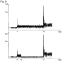
- Tq1 indicates a torque of the servo motor 25 for the first tool change unit 13UL
- Tq2 indicates a torque of the servo motor 25 for the second tool change unit 13UR.
- t1 is a time at which movement of the first tool change unit 13UL and the second tool change unit 13UR are started.
- step S12 the control unit 20b outputs a stop command to the servo motor 25 for the first tool change unit 13UL so that the first tool change unit 13UL is stopped and fixed at a reference position Pst ( Figure 5B , a time t2 in Figure 6 ).
- the reference position Pst is set in advance to the right side of the initial position of the first tool change unit 13UL, that is, a predetermined position closer to the second tool change unit 13UR.
- the control unit 20b refers to the position of the first tool change unit 13UL specified by the encoder 29, and determines whether or not the first tool change unit 13UL has reached the reference position Pst.
- the second tool change unit 13UR continues to move toward the first tool change unit 13UL ( Figure 5C ).
- the second tool change unit 13UR abuts on the upper tool P4 located on the far right side.
- the upper tool P4 is pushed by the second tool change unit 13UR, which causes the upper tool P4 to be moved toward the first tool change unit 13UL.
- the upper tool P3, the upper tool P2, and the upper tool P1 are pushed one after another by the second tool change unit 13UR.
- the four upper tools P1 to P4 are moved to the first tool change unit 13UL in a state of being in close contact with each other.
- step S13 the calculation unit 20a determines whether or not the torques Tq1 and Tq2 of the respective servo motors 25 are larger than a torque threshold value Tth.
- the first tool change unit 13UL is fixed at the reference position Pst. Therefore, when the four upper tools P1 to P4 are brought together at the first tool change unit 13UL, the second tool change unit 13UR can no longer move the four upper tools P1 to P4.
- the servo motor 25 for the second tool change unit 13UR becomes overloaded, and a large torque change is generated (a time t4 in Figure 6 ).
- the first tool change unit 13UL is fixed at the reference position Pst. Therefore, when the four upper tools P1 to P4 moved by the second tool change unit 13UR abut on the first tool change unit 13UL, a large tongue change also occurs in the servo motor 25 for the first tool change unit 13UL (a time t4 in Figure 6 ).
- the torque threshold value Tth is for identifying an excessive torque generated in each servo motor 25 when the upper tools P1 to P4 are brought together at the first tool change unit 13UL.
- An optimum value obtained through experiments and simulations is set to the torque threshold value Tth, which is stored in the memory 20c.
- step S13 the calculation unit 20a compares the torques Tq1 and Tq2 from the respective servo motors 25 with the torque threshold value Tth, so as to determine whether or not the four upper tools P1 to P4 are brought together at the first tool change unit 13UL as a result of a movement of the second tool change unit 13UR. If a positive determination is made in step S13, that is, if the torques Tq1 and Tq2 of the respective servo motors 25 are larger than the torque threshold value Tth, a positive determination is made in step S13 and the process proceeds to step S14.
- step S13 if a negative determination is made in step S13, that is, if the torques Tq1 and Tq2 of both or one of the servo motors 25 are equal to or less than the torque threshold value Tth, a negative determination is made in step S13 and the process returns to step S13.
- step S14 the control unit 20b outputs a stop command to the servo motor 25 for the second tool change unit 13UR so that the second tool change unit 13UR is stopped.
- This processing in the step S14 is executed by the positive determination in step S13, that is, a determination that the four upper tools P1 to P4 are brought together at the first tool change unit 13UL as a result of the movement of the second tool change unit 13UR.
- the servo motor 25 may not stop immediately and thus the second tool change unit 13UR may advance by inertia. This results in a state in which the four upper tools P1 to P4 are pushed together by the second tool change unit 13UR. In this case, vibrations of the upper tools P1 to P4 may be transmitted to the servo motor 25 and regarded as an abnormality of the servo motor 25. In addition, there is a possibility that an end position Peg, which will be described later, cannot be recognized correctly.
- step S15 the control unit 20b performs a correction operation, specifically, an operation of causing the second tool change unit 13UR to travel in the reverse direction by a predetermined amount.
- the control unit 20b calculates, based on the moving speed of the second tool change unit 13UR and the weights of the upper tools P1 to P4, an amount of inertia movement in which the second tool change unit 13UR moves by inertia after the stop command. Then, the control unit 20b controls the servo motor 25 so as to cause the second tool change unit 13UR to travel in the reverse direction by the amount of inertia movement. Note that this correction operation may be performed when the first tool change unit 13UL is stopped.
- step S16 the control unit 20b refers to the detection signal from the encoder 29 and specifies a stop position of the second tool change unit 13UR. Then, the control unit 20b specifies the end position Peg of the four upper tools P1 to P4 based on the stop position of the second tool change unit 13UR ( Figure 5D ). The end position Peg corresponds to a boundary surface between the upper tool P4 located closest to the second tool change unit 13UR and the second tool change unit 13UR.
- step S17 the calculation unit 20a determines any excess or deficiency of the tool with respect to the upper tools P1 to P4 that have been brought together. If any of the upper tools P1 to P4 is manually removed, a difference is produced between the length from the reference position Pst to the end position Peg and the total sum of the divided lengths of the upper tools P1 to P4 that should be on the tool installation unit 9U.
- the calculation unit 20a acquires layout information from, for example, the host device 50.
- This layout information defines a layout of the tools to be used for the bending, and indicates information of the upper tools that should be on the tool installation unit 9U.
- the layout information includes information on the tool ID, a divided length, an installation position, and the like.
- the calculation unit 20a calculates the total sum of the divided lengths of the four upper tools P1 to P4 based on the layout information. When the length from the reference position Pst to the end position Peg coincides with the total sum of the divided lengths of the upper tools P1 to P4, the calculation unit 20a determines that there is no excess or deficiency of the tool. On the other hand, if the length from the reference position Pst to the end position Peg does not coincide with the total sum of the divided lengths of the upper tools P1 to P4, the calculation unit 20a determines that there is some excess or deficiency of the tool.
- the calculation unit 20a acquires tool information.
- the tool information is information on the four upper tools P1 to P4 that have been brought together, in which the tool ID is associated with an arrangement order of the tool from the end position Peg for each of the four upper tools P1 to P4.
- the calculation unit 20a can acquire the tool information based on information generated by a user from the four upper tools P1 to P4 that have been brought together.
- the calculation unit 20a can acquire the information generated by the user via, for example, the host device 50. Further, when a device capable of automatically acquiring the tool ID and the arrangement order of the tool from the end position Peg is provided for each of the four upper tools P1 to P4 that have been brought together, the tool information can be acquired through this device. Further, if there is no excess or deficiency of the tool, the calculation unit 20a can also acquire the tool information from the layout information described above.
- step S19 the calculation unit 20a acquires the storage information from the memory 20c.
- step S20 the calculation unit 20a controls one or both of the tool change units 13UL and 13UR and executes a storage operation of picking up the four upper tools P1 to P4, which have been brought together, in order starting with the upper tool closest to the end position Peg so as to be stored in the tool storage positions.
- the calculation unit 20a specifies, based on the tool information and the storage information, the tool storage positions in which the four upper tools P1 to P4 are stored, respectively.
- the tool storage position is specified with reference to the tool ID.
- the calculation unit 20a determines the upper tools P1 to P4 to be stored according to the arrangement order of the upper tools P1 to P4 from the end position Peg.
- the first one to be stored is the upper tool P4 at the end position Peg, followed by the upper tools P3, the upper tool P2, and the upper tool P1. These upper tools P1 to P3 are to be stored in this order.
- the calculation unit 20a can specify, based on the end position Peg and the divided lengths of the upper tools P1 to P4, the end position of the upper tools P1 to P4 to be stored (the boundary positions with the adjacent tools).
- the end position of the upper tool P4 is the above-mentioned end position Peg
- the end position of the upper tool P3 is a position shifted to the left by the divided length of the upper tool P4 from the above-mentioned end position Peg.
- the end position of the upper tool P2 is a position shifted to the left by the divided lengths of the upper tools P4 and P3 from the above-mentioned end position Peg
- the end position of the upper tool P1 is a position shifted to the left by the divided lengths of the upper tools P4, P3, and P2 from the above-mentioned end position Peg.
- the engagement holes H for holding the upper tools P1 to P4 are provided at the centers of the upper tools P1 to P4 in the left-right direction. Therefore, the calculation unit 20a specifies, based on the end position of the upper tools P1 to P4 to be stored and the divided lengths of the tools, holding positions at which the upper tools P1 to P4 to be stored are held by the tool change units 13UR and 13UL.
- control unit 20b controls the tool change units 13UR and 13UL based on the holding positions thereof, and removes the upper tools P1 to P4 to be stored from the tool installation unit 9U. Then, the control unit 20b controls the tool change units 13UR and 13UL to store the upper tools P1 to P4 in the tool storage positions of the tool storage unit 17U.
- the automatic tool changer 13U includes the pair of servo motors 25, the first and second tool change units 13UL and 13UR configured to be driven respectively by the pair of servo motors 25 and move along the arrangement direction of the tools of the tool installation unit 9U, a torque detection unit 27 configured to detect a torque of each of the pair of servo motors 25, and a control device 20 configured to control the operations of the first and second tool change units 13UL and 13UR.
- the control device 20 fixes the first tool change unit 13UL at the predetermined reference position Pst, moves the second tool change unit 13UR toward the first tool change unit 13UL, and determines, based on the torque change of each servo motor 25 detected by the torque detection unit 27, that the plurality of upper tools P1 to P4 are brought together at the first tool change unit 13UL as a result of the movement of the second tool change unit 13UR.
- the upper tools P1 to P4 can be brought together at the first tool change unit 13UL. Further, since the first tool change unit 13UL is fixed at the reference position Pst, it is possible to accurately determine that the plurality of upper tools P1 to P4 are brought together at the first tool change unit 13UL by paying attention to the torque change of each servo motor 25.
- control device 20 specifies the end position Peg of the plurality of upper tools P1 to P4 that have been brought together based on the torque change of each servo motor 25 detected by the torque detection unit 27 and the position of the second tool change unit 13UR.
- the positions of the plurality of upper tools P1 to P4 can be recognized between the reference position Pst and the end position Pegs.
- control device 20 determines excess or deficiency of the tool based on the layout information of the tools to be installed on the tool installation unit 9U and the length from the reference position Pst to the end position Peg.
- the control device 20 acquires the tool information in which the tool ID for identifying the tool is associated with the arrangement order of the tool from the end position Peg for each of the plurality upper tools P1 to P4 that have been brought together. Similarly, the control device 20 acquires the storage information in which the tool ID is associated with the tool storage position in the tool storage unit 17U. Then, the control device 20 specifies, based on the tool information and the storage information, the tool storage position for each of the plurality of upper tools P1 to P4 that have been brought together.
- the tool storage position can be specified for each of the plurality of upper tools P1 to P4 that have been brought together. Thereby, the upper tools P1 to P4 can be stored into the tool storage unit 17U.
- control device 20 controls one or both of the pair of tool change units 13UL and 13UR and executes the storage operation of picking up the upper tools P1 to P4 in order starting with the upper tool closest to the end position Peg so as to be stored in the tool storage positions.
- the plurality of upper tools P1 to P4 can be automatically stored by using the pair of tool change units 13UL and 13UR.
- the control device 20 determines the upper tools P1 to P4 to be stored according to the arrangement order of the upper tools P1 to P4 from the end position Peg, and specifies the holding positions at which the tools are held by the tool change units 13UL and 13UR based on the end position of the upper tools P1 to P4 to be stored and the divided lengths of the tools. Further, the control device 20 picks up, from the tool installation unit 9U, the tools to be stored based on the holding positions thereof so as to be stored in the tool storage positions.
- the upper tools P1 to P4 can be appropriately held. Thereby, the upper tools P1 to P4 on the tool installation unit 9U can be reliably picked up and stored in the tool storage positions.
- control device 20 determines that the plurality of upper tools P1 to P4 are brought together when the torque Tq2 of the servo motor 25 for driving the second tool change unit 13UR is equal to or higher than the torque threshold value Tth.
- the movement of the second tool change unit 13UR is forcibly regulated.
- the servo motor 25 for driving the second tool change unit 13UR becomes overloaded, and a large torque change is generated.
- the torque change can be specified. As a result, it can be appropriately determined that the plurality of upper tools P1 to P4 are brought together.
- control device 20 determines that the plurality of upper tools P1 to P4 are brought together when not only the torque Tq2 of the servo motor 25 for driving the second tool change unit 13UR but also the torque Tq1 of the servo motor 25 for driving the first tool change unit 13UL are equal to or higher than the torque threshold value Tth.
- the control device 20 outputs the stop command for stopping the second tool change unit 13UR when the plurality of upper tools P1 to P4 are brought together at the first tool change unit 13UL. Further, the control device 20 calculates the amount of inertia movement in which the second tool change unit 13UR moves by inertia after the stop command is output based on the moving speed of the second tool change unit 13UR and the weights of the plurality of upper tools P1 to P4. Then, the control device 20 causes the second tool change unit 13UR to travel in the reverse direction based on the amount of inertia movement.
- the stop position may be shifted due to inertia. This results in a state in which the plurality of upper tools P1 to P4 are pushed by the second tool change unit 13UR, vibrations and the like of the tools may be regarded as an abnormality of the servo motor 25. In this respect, it is possible to cause the second tool change unit 13UR to travel in the reverse direction, and to return the second tool change unit 13UR to an original stop position.
- the position shift of the second tool change unit 13UR can be suppressed. Thereby, the automatic tool change can be performed appropriately.
- the tool change method is a method of storing, in the tool storage unit 17U, the plurality of tools installed side by side on the tool installation unit 9U of the press brake 1.
- the fixing unit for regulating the movement of the upper tools P1 to P4 is provided at the reference position Pst of the tool installation unit 9U, and the plurality of upper tools P1 to P4 installed on the tool installation unit 9U are moved to one side along the arrangement direction of the tools, so that the plurality of upper tools P1 to P4 are brought together at the fixing unit.
- the plurality of upper tools P1 to P4 can be put together with respect to the reference position Pst.
- the plurality of upper tools P1 to P4 it is possible to recognize the positions of the plurality of upper tools P1 to P4.
- the upper tools P1 to P4 are brought together by using the pair of tool change units 13UL and 13UR.
- the tool change method according to the present embodiment may be a method of manually moving and putting together the upper tools P1 to P4 with respect to the reference position Pst.
- the first tool change unit 13UL is used as the fixing unit.
- any object other than the first tool change unit 13UL may be used as long as the object regulates the movement of the upper tools P1 to P4.
- the tool change units 13UL and 13UR that automatically perform tool change store in the tool storage unit 17U, the plurality of upper tools P1 to P4 that have been brought together.
- An automatic tool changer (13U) for storing, in a tool storage unit (17U), a plurality of tools (P1,P2,P3,P4) installed side by side on a tool installation unit (9U) of a press brake (1), the automatic tool changer (13U) comprising: a pair of servo motors (25); first and second tool change units (13UL,13UR) configured to be driven respectively by the pair of servo motors (25) and move along an arrangement direction of the tools (P1,P2,P3,P4) on the tool installation unit (9U); a torque detection unit (27) configured to detect a torque of each of the pair of servo motors (25); and a control device (20) configured to control operations of the first and second tool change units (13UL,13UR), wherein the control device (20) is configured to fix the first tool change unit (13UL) at a predetermined reference position (Pst), move the second tool change unit (13UR) toward the first tool change unit (13UL), and determine, based on a torque change of each of the
- the automatic tool changer (13U) according to clause 1, wherein the control device (20) is configured to specify an end position (Peg) of the plurality of tools (P1,P2,P3,P4) that have been brought together based on the torque change of each servo motor (25) detected by the torque detection unit (27) and a position of the second tool change unit (13UR).
- the control device (20) is configured to specify an end position (Peg) of the plurality of tools (P1,P2,P3,P4) that have been brought together based on the torque change of each servo motor (25) detected by the torque detection unit (27) and a position of the second tool change unit (13UR).
- control device (20) is configured to determine excess or deficiency of the tool (P1,P2,P3,P4) based on layout information of the tools (P1,P2,P3,P4) to be installed on the tool installation unit (9U) and a length from the reference position (Pst) to the end position (Peg).
- the automatic tool changer (13U) according to clause 2 or 3, wherein the control device (20) is configured to acquire, for each of the plurality of tools (P1,P2,P3,P4) that have been brought together, tool information in which a tool ID for identifying the tool (P1,P2,P3,P4) is associated with an arrangement order of the tool (P1,P2,P3,P4) from the end position (Peg), acquire storage information in which the tool ID is associated with a tool storage position in the tool storage unit (17U), and specify, based on the tool information and the storage information, the tool storage position for each of the plurality of tools (P1,P2,P3,P4) that have been brought together.
- the control device (20) is configured to acquire, for each of the plurality of tools (P1,P2,P3,P4) that have been brought together, tool information in which a tool ID for identifying the tool (P1,P2,P3,P4) is associated with an arrangement order of the tool (P1,P2,P3,P4) from the end position (Peg), acquire storage information in which the tool
- the automatic tool changer (13U) according to clause 4, wherein the control device (20) is configured to control one or both of the first and second tool change units (13UL,13UR) and execute a storage operation of picking up the tools (P1,P2,P3,P4) in order starting with a tool (P1,P2,P3,P4) closest to the end position (Peg) so as to be stored in the tool storage positions.
- the automatic tool changer (13U) according to clause 5, wherein the control device (20) is configured to determine the tools (P1,P2,P3,P4) to be stored according to the arrangement order of the tools (P1,P2,P3,P4) from the end position (Peg), specify holding positions at which the tools (P1,P2,P3,P4) are held by the tool change units (13UL,13UR) based on the end position (Peg) of the tools (P1,P2,P3,P4) to be stored and divided lengths of the tools (P1,P2,P3,P4), and pick up, from the tool installation unit (9U), the tools (P1,P2,P3,P4) to be stored based on the holding positions thereof so as to be stored in the tool storage positions.
- the automatic tool changer (13U) according to any one of clauses 1 to 6, wherein the control device (20) is configured to determine that the plurality of tools (P1,P2,P3,P4) are brought together when the torque of the servo motor (25) for driving the second tool change unit (13UR) is equal to or higher than a torque threshold value.
- the automatic tool changer (13U) according to clause 7, wherein the control device (20) is configured to determine that the plurality of tools (P1,P2,P3,P4) are brought together when not only the torque of the servo motor (25) for driving the second tool change unit (13UR) but also the torque of the servo motor (25) for driving the first tool change unit (13UL) are equal to or higher than the torque threshold value.
- the automatic tool changer (13U) according to any one of clauses 1 to 8, wherein the control device (20) is configured to output a stop command for stopping the second tool change unit (13UR) when it is determined that the plurality of tools (P1,P2,P3,P4) are brought together at the first tool change unit (13UL), calculate an amount of inertia movement in which the second tool change unit (13UR) moves by inertia after the stop command is output based on a moving speed of the second tool change unit (13UR) and weights of the plurality of tools (P1,P2,P3,P4), and cause the second tool change unit (13UR) to travel in a reverse direction based on the amount of inertia movement.
- a tool change method of storing, in a tool storage unit (17U), a plurality of tools (P1,P2,P3,P4) installed side by side on a tool installation unit of a press brake (1) comprising: placing a fixing unit configured to regulate a movement of the tool (P1,P2,P3,P4) at a reference position (Pst); moving the plurality of tools (P1,P2,P3,P4) installed on the tool installation unit (9U) to one side along an arrangement direction of the tools (P1,P2,P3,P4) on the tool installation unit (9U); and bringing the plurality of tools (P1,P2,P3,P4) together at the fixing unit.
- the tool change method further comprising, by a tool change unit (13UL,13UR) configured to automatically perform tool change, storing the plurality of tools (P1,P2,P3,P4) that have been brought together in the tool storage unit (17U).
Landscapes
- Engineering & Computer Science (AREA)
- Mechanical Engineering (AREA)
- Bending Of Plates, Rods, And Pipes (AREA)
- Automatic Tool Replacement In Machine Tools (AREA)
- Mounting, Exchange, And Manufacturing Of Dies (AREA)
Abstract
Description
- The present disclosure relates to an automatic tool changer and a tool change method.
- A press brake is a processing machine that performs bending of a material such as a sheet metal by using tools installed on tool installation units of upper and lower tables. Among press brakes, a press brake is known that is equipped with an automatic tool changer (also referred to as an ACT) for automatically performing tool change between a tool storage unit that stores the tools and a tool installation unit (see, for example,
Patent Literatures 1 and 2). - Further, Patent Literature 3 discloses a bending machine provided with a back gauge for positioning a material. In Patent Literature 3, a technique is disclosed in which a side gauge attached to an abutment of the back gauge is moved and brought into contact with a punch or a die so that a position of the punch or the die is detected.
-
- Patent Literature 1:
Japanese Patent Application Laid-Open Publication No. 2000-71028 - Patent Literature 2:
Japanese Patent Application Laid-Open Publication No. 2014-91137 - Patent Literature 3:
Japanese Patent Application Laid-Open Publication No. H09-295059 - In some cases, when a tool placement by the automatic change fails due to a warning or a halfway termination, or when the tool is unclamped by an operation other than the automatic change, the tool position may be shifted. Since it is not possible to identify where the tool is located in the tool installation unit, there arises such a problem that the tool cannot be automatically stored by the automatic tool changer.
- The present disclosure has been made in view of such circumstances, and an object of the present disclosure is to provide an automatic tool changer and a tool change method capable of recognizing a tool position even when the tool position is shifted.
- According to a first aspect of one or more embodiments, an automatic tool changer for storing, in a tool storage unit, a plurality of tools installed side by side on a tool installation unit of a press brake is provided. The present automatic tool changer includes a pair of servo motors, first and second tool change units configured to be driven respectively by the pair of servo motors and move along an arrangement direction of the tools on the tool installation unit, a torque detection unit configured to detect a torque of each of the pair of servo motors, and a control device configured to control operations of the pair of the tool change units, in which the control device is configured to fix the first tool change unit at a predetermined reference position, move the second tool change unit toward the first tool change unit, and determine, based on a torque change of each of the servo motors detected by the torque detection unit, that the plurality of tools are brought together at the first tool change unit as a result of a movement of the second tool change unit.
- Further, according to a second aspect of the one or more embodiments, a tool change method is provided by which a plurality of tools installed side by side on a tool installation unit of a press brake are stored in a tool storage unit. The present tool change method includes placing a fixing unit configured to regulate a movement of the tool at a reference position, moving the plurality of tools installed on the tool installation unit to one side along an arrangement direction of the tools on the tool installation unit, and bringing the plurality of tools together at the fixing unit.
- According to the present disclosure, it is possible to recognize a tool position even when the tool position is shifted.
-
- [
Figure 1] Figure 1 is a front view schematically showing a configuration of a press brake including an automatic tool changer according to an embodiment. - [
Figure 2] Figure 2 is a cross-sectional view schematically showing the configuration of the press brake including the automatic tool changer according to the present embodiment. - [
Figure 3] Figure 3 is a block diagram showing a configuration of a control device of the automatic tool changer according to the present embodiment. - [
Figure 4] Figure 4 is a flowchart showing a tool change procedure. - [
Figure 5A] Figure 5A is an explanatory diagram showing an operation of a tool change unit. - [
Figure 5B] Figure 5B is an explanatory diagram showing an operation of the tool change unit. - [
Figure 5C] Figure 5C is an explanatory diagram showing an operation of the tool change unit. - [
Figure 5D] Figure 5D is an explanatory diagram showing an operation of the tool change unit. - [
Figure 6] Figure 6 is an explanatory diagram showing transitions of torques of servo motors. - Hereinafter, a press brake including an automatic tool changer according to an embodiment will be described. In
Figure 1 or2 , apress brake 1 is a processing machine that performs bending of a material W such as a sheet metal by a pair of tools. Thepress brake 1 includes an upper table 5U, a lower table 5L, andautomatic tool changers - The upper table 5U is provided above left and
right side frames hydraulic cylinders side frames - The upper table 5U is provided with a
tool installation unit 9U on which an upper tool P is installed. Thetool installation unit 9U extends in the left-right direction (X-axis direction). Depending on a layout of the tools to be used for the bending, a required number of tool stages in which one or more upper tools P are combined are installed side by side on thetool installation unit 9U. When thepress brake 1 is viewed from the front, the upper tools P installed on thetool installation unit 9U are arranged side by side along the left-right direction. - A
guide member 11U extending in the left-right direction is provided on the rear side (back side in the Y-axis direction) of the upper table 5U. Theguide member 11U is provided with theautomatic tool changer 13U. Theautomatic tool changer 13U changes the upper tool P between atool storage unit 17U on the rear side of the upper table 5U and thetool installation unit 9U. Changing of the tool includes storing the upper tool P into thetool storage unit 17U, taking out the upper tool P from thetool storage unit 17U, installing the upper tool P on thetool installation unit 9U, and taking out the upper tool P from thetool installation unit 9U. - The
automatic tool changer 13U includes the left and right (a pair of) tool change units 13UL and 13UR. The respective tool change units 13UL and 13UR are configured to be movable in the left-right direction along theguide member 11U. The pair of tool change units 13UL and 13UR are respectively driven by individual servo motors. - The tool change units 13UL and 13UR are each provided with a tool holding member (finger) 15 for holding the upper tool P by engaging with an engagement hole H provided in the tool (upper tool P). The
tool holding member 15 is configured to be movable forward and backward in the front-rear direction (Y-axis direction) so as to engage with the engagement hole H and disengage from the engagement hole H. - When holding the upper tool P installed on the
tool installation unit 9U, the tool change units 13UL and 13UR are moved in the left-right direction so as to be positioned on the rear side of the upper tool P to be held. When thetool holding member 15 is switched to a forward movement state, thetool holding member 15 is inserted into the engagement hole H. - Further, the
tool holding member 15 can cause the upper tool P to move in the left-right direction along thetool installation unit 9U. Specifically, thetool holding member 15 is switched to the forward movement state when the upper tool P does not exist in front of thetool holding member 15. When the tool change units 13UL and 13UR move in the left-right direction, thetool holding member 15 in the forward movement state abuts on an end portion of the upper tool P in the left-right direction. When the tool change units 13UL and 13UR continue to move in the left-right direction, an external force for moving the upper tool P is applied, which moves the upper tool P in the left-right direction. - Similar to the upper table 5U, the lower table 5L is provided with a
tool installation unit 9L as well on which a lower tool D is installed. The configuration of thetool installation unit 9L is the same as that of thetool installation unit 9U. - A
guide member 11L extending in the left-right direction is provided on the rear side (back side in the Y-axis direction) of the lower table 5L, and theguide member 11L is provided with anautomatic tool changer 13L. Theautomatic tool changer 13L changes the lower tool D between atool storage unit 17L on the rear side of the lower table 5L and the tool installation unit 9L.Thisautomatic tool changer 13L includes a pair of tool change units 13LL and 13LR. The configuration of theautomatic tool changer 13L is the same as that of theautomatic tool changer 13U, and detailed description thereof will be omitted. - In
Figure 3 , acontrol device 20 controls operations of theautomatic tool changers control device 20 is mainly configured with a CPU, a ROM, a RAM, and an I/O interface. Thecontrol device 20 controls the operations of theautomatic tool changers - The
control device 20 supplies eachservo motor 25 with a control command for controlling theservo motor 25. Further, detection signals are supplied to thecontrol device 20 from atorque detection unit 27 that detects a torque of eachservo motor 25 and anencoder 29 that detects a rotation speed of theservo motor 25, respectively. Note that theservo motor 25, thetorque detection unit 27, and theencoder 29 are provided corresponding to the four tool change units 13UL, 13UR, 13LL, and 13LR, respectively, but only one set of configurations is representatively shown inFigure 3 . - Further, a
host device 50 is connected to thecontrol device 20. Thehost device 50 is, for example, an NC device that controls thepress brake 1, and thecontrol device 20 can acquire necessary information from thehost device 50. - The
control device 20 functionally has acalculation unit 20a, acontrol unit 20b, and amemory 20c. - The
calculation unit 20a monitors the torque of theservo motor 25 based on the detection signal supplied from thetorque detection unit 27. - The
control unit 20b controls theservo motor 25 to control the position of each of the tool change units 13UL, 13UR, 13LL, and 13LR. In this position control, thecontrol unit 20b can recognize the position of each of the tool change units 13LL, 13LR, 13UL, and 13UR in the left-right direction based on the detection signal supplied from theencoder 29. Further, in addition to the position control, thecontrol unit 20b also controls a forward and backward operation of thetool holding member 15 carried by each of the tool change units 13UL, 13UR, 13LL, and 13LR, and a movement of each of the tool change units 13UL, 13UR, 13LL, and 13LR required for tool change. - The
memory 20c stores various information. Thememory 20c stores information on a torque threshold value for determining a torque change of eachservo motor 25. Thememory 20c stores information on a reference position. - The
memory 20c stores a tool ID for identifying each tool (the upper tool P and the lower tool D) owned by thepress brake 1, and storage information indicating correspondence with a storage position in thetool storage units - Hereinafter, a tool change procedure by the
automatic tool changers Figures 4 to 6 . This tool change procedure is a procedure for storing, into thetool storage unit tool installation unit control device 20. - Note that in the following description, an operation of the
automatic tool changer 13U corresponding to the upper table 5U will be described, but an operation of theautomatic tool changer 13L corresponding to the lower table 5L is also the same. Further, of the pair of tool change units 13UL and 13UR, one tool change unit 13UL located on the left side ofFigure 1 is referred to as a first tool change unit 13UL, and the other tool change unit 13UR located on the right side ofFigure 1 is referred to as a second tool change unit 13UR. It is assumed that a plurality of upper tools, for example, four upper tools P1 to P4 are installed on thetool installation unit 9U. - In performing this procedure, as shown in
Figure 1 , thecontrol unit 20b arranges the pair of tool change units 13UL and 13UR at initial positions. The left end portion of theguide member 11U is the initial position of the first tool change unit 13UL, and the right end portion of theguide member 11U is the initial position of the second tool change unit 13UR. In a state in which the first tool change unit 13UL and the second tool change unit 13UR are arranged at the initial positions thereof, the four upper tools P1 to P4 exist between the first tool change unit 13UL and the second tool change unit 13UR. - First, in step S10, the
control unit 20b starts moving the first tool change unit 13UL and the second tool change unit 13UR. Specifically, thecontrol unit 20b controls theservo motor 25 for driving the first tool change unit 13UL so that the first tool change unit 13UL is moved toward the right side, that is, toward the second tool change unit 13UR (Figure 5A ). Similarly, thecontrol unit 20b controls theservo motor 25 for driving the second tool change unit 13UR so that the second tool change unit 13UR is moved toward the left side, that is, toward the first tool change unit 13UL (Figure 5A ). - In step S11, the
calculation unit 20a starts torque detection of theservo motors 25 based on the detection signal supplied from thetorque detection unit 27. The torque detection is performed on each of theservo motor 25 for driving the first tool change unit 13UL and theservo motor 25 for driving the second tool change unit 13UR. - Here, in
Figure 6 , "Tq1" indicates a torque of theservo motor 25 for the first tool change unit 13UL, and "Tq2" indicates a torque of theservo motor 25 for the second tool change unit 13UR. InFigure 6 , "t1" is a time at which movement of the first tool change unit 13UL and the second tool change unit 13UR are started. - In step S12, the
control unit 20b outputs a stop command to theservo motor 25 for the first tool change unit 13UL so that the first tool change unit 13UL is stopped and fixed at a reference position Pst (Figure 5B , a time t2 inFigure 6 ). The reference position Pst is set in advance to the right side of the initial position of the first tool change unit 13UL, that is, a predetermined position closer to the second tool change unit 13UR. Thecontrol unit 20b refers to the position of the first tool change unit 13UL specified by theencoder 29, and determines whether or not the first tool change unit 13UL has reached the reference position Pst. - On the other hand, the second tool change unit 13UR continues to move toward the first tool change unit 13UL (
Figure 5C ). When the second tool change unit 13UR continues to move, the second tool change unit 13UR abuts on the upper tool P4 located on the far right side. The upper tool P4 is pushed by the second tool change unit 13UR, which causes the upper tool P4 to be moved toward the first tool change unit 13UL. By repeating this operation, the upper tool P3, the upper tool P2, and the upper tool P1 are pushed one after another by the second tool change unit 13UR. Finally, the four upper tools P1 to P4 are moved to the first tool change unit 13UL in a state of being in close contact with each other. - In step S13, the
calculation unit 20a determines whether or not the torques Tq1 and Tq2 of therespective servo motors 25 are larger than a torque threshold value Tth. The first tool change unit 13UL is fixed at the reference position Pst. Therefore, when the four upper tools P1 to P4 are brought together at the first tool change unit 13UL, the second tool change unit 13UR can no longer move the four upper tools P1 to P4. Theservo motor 25 for the second tool change unit 13UR becomes overloaded, and a large torque change is generated (a time t4 inFigure 6 ). - Further, in the present embodiment, the first tool change unit 13UL is fixed at the reference position Pst. Therefore, when the four upper tools P1 to P4 moved by the second tool change unit 13UR abut on the first tool change unit 13UL, a large tongue change also occurs in the
servo motor 25 for the first tool change unit 13UL (a time t4 inFigure 6 ). - The torque threshold value Tth is for identifying an excessive torque generated in each
servo motor 25 when the upper tools P1 to P4 are brought together at the first tool change unit 13UL. An optimum value obtained through experiments and simulations is set to the torque threshold value Tth, which is stored in thememory 20c. - In other words, in step S13, the
calculation unit 20a compares the torques Tq1 and Tq2 from therespective servo motors 25 with the torque threshold value Tth, so as to determine whether or not the four upper tools P1 to P4 are brought together at the first tool change unit 13UL as a result of a movement of the second tool change unit 13UR. If a positive determination is made in step S13, that is, if the torques Tq1 and Tq2 of therespective servo motors 25 are larger than the torque threshold value Tth, a positive determination is made in step S13 and the process proceeds to step S14. On the other hand, if a negative determination is made in step S13, that is, if the torques Tq1 and Tq2 of both or one of theservo motors 25 are equal to or less than the torque threshold value Tth, a negative determination is made in step S13 and the process returns to step S13. - In step S14, the
control unit 20b outputs a stop command to theservo motor 25 for the second tool change unit 13UR so that the second tool change unit 13UR is stopped. This processing in the step S14 is executed by the positive determination in step S13, that is, a determination that the four upper tools P1 to P4 are brought together at the first tool change unit 13UL as a result of the movement of the second tool change unit 13UR. - In some cases, even if the stop command is output to the
servo motor 25, theservo motor 25 may not stop immediately and thus the second tool change unit 13UR may advance by inertia. This results in a state in which the four upper tools P1 to P4 are pushed together by the second tool change unit 13UR. In this case, vibrations of the upper tools P1 to P4 may be transmitted to theservo motor 25 and regarded as an abnormality of theservo motor 25. In addition, there is a possibility that an end position Peg, which will be described later, cannot be recognized correctly. - Therefore, in step S15, the
control unit 20b performs a correction operation, specifically, an operation of causing the second tool change unit 13UR to travel in the reverse direction by a predetermined amount. Specifically, thecontrol unit 20b calculates, based on the moving speed of the second tool change unit 13UR and the weights of the upper tools P1 to P4, an amount of inertia movement in which the second tool change unit 13UR moves by inertia after the stop command. Then, thecontrol unit 20b controls theservo motor 25 so as to cause the second tool change unit 13UR to travel in the reverse direction by the amount of inertia movement. Note that this correction operation may be performed when the first tool change unit 13UL is stopped. - In step S16, the
control unit 20b refers to the detection signal from theencoder 29 and specifies a stop position of the second tool change unit 13UR. Then, thecontrol unit 20b specifies the end position Peg of the four upper tools P1 to P4 based on the stop position of the second tool change unit 13UR (Figure 5D ). The end position Peg corresponds to a boundary surface between the upper tool P4 located closest to the second tool change unit 13UR and the second tool change unit 13UR. - In step S17, the
calculation unit 20a determines any excess or deficiency of the tool with respect to the upper tools P1 to P4 that have been brought together. If any of the upper tools P1 to P4 is manually removed, a difference is produced between the length from the reference position Pst to the end position Peg and the total sum of the divided lengths of the upper tools P1 to P4 that should be on thetool installation unit 9U. - Then, the
calculation unit 20a acquires layout information from, for example, thehost device 50. This layout information defines a layout of the tools to be used for the bending, and indicates information of the upper tools that should be on thetool installation unit 9U. The layout information includes information on the tool ID, a divided length, an installation position, and the like. - The
calculation unit 20a calculates the total sum of the divided lengths of the four upper tools P1 to P4 based on the layout information. When the length from the reference position Pst to the end position Peg coincides with the total sum of the divided lengths of the upper tools P1 to P4, thecalculation unit 20a determines that there is no excess or deficiency of the tool. On the other hand, if the length from the reference position Pst to the end position Peg does not coincide with the total sum of the divided lengths of the upper tools P1 to P4, thecalculation unit 20a determines that there is some excess or deficiency of the tool. - In step S18, the
calculation unit 20a acquires tool information. The tool information is information on the four upper tools P1 to P4 that have been brought together, in which the tool ID is associated with an arrangement order of the tool from the end position Peg for each of the four upper tools P1 to P4. Thecalculation unit 20a can acquire the tool information based on information generated by a user from the four upper tools P1 to P4 that have been brought together. Thecalculation unit 20a can acquire the information generated by the user via, for example, thehost device 50. Further, when a device capable of automatically acquiring the tool ID and the arrangement order of the tool from the end position Peg is provided for each of the four upper tools P1 to P4 that have been brought together, the tool information can be acquired through this device. Further, if there is no excess or deficiency of the tool, thecalculation unit 20a can also acquire the tool information from the layout information described above. - In step S19, the
calculation unit 20a acquires the storage information from thememory 20c. - In step S20, the
calculation unit 20a controls one or both of the tool change units 13UL and 13UR and executes a storage operation of picking up the four upper tools P1 to P4, which have been brought together, in order starting with the upper tool closest to the end position Peg so as to be stored in the tool storage positions. - Specifically, the
calculation unit 20a specifies, based on the tool information and the storage information, the tool storage positions in which the four upper tools P1 to P4 are stored, respectively. The tool storage position is specified with reference to the tool ID. - The
calculation unit 20a determines the upper tools P1 to P4 to be stored according to the arrangement order of the upper tools P1 to P4 from the end position Peg. The first one to be stored is the upper tool P4 at the end position Peg, followed by the upper tools P3, the upper tool P2, and the upper tool P1. These upper tools P1 to P3 are to be stored in this order. - In this case, the
calculation unit 20a can specify, based on the end position Peg and the divided lengths of the upper tools P1 to P4, the end position of the upper tools P1 to P4 to be stored (the boundary positions with the adjacent tools). For example, the end position of the upper tool P4 is the above-mentioned end position Peg, and the end position of the upper tool P3 is a position shifted to the left by the divided length of the upper tool P4 from the above-mentioned end position Peg. The end position of the upper tool P2 is a position shifted to the left by the divided lengths of the upper tools P4 and P3 from the above-mentioned end position Peg, and the end position of the upper tool P1 is a position shifted to the left by the divided lengths of the upper tools P4, P3, and P2 from the above-mentioned end position Peg. - Further, the engagement holes H for holding the upper tools P1 to P4 are provided at the centers of the upper tools P1 to P4 in the left-right direction. Therefore, the
calculation unit 20a specifies, based on the end position of the upper tools P1 to P4 to be stored and the divided lengths of the tools, holding positions at which the upper tools P1 to P4 to be stored are held by the tool change units 13UR and 13UL. - Then, the
control unit 20b controls the tool change units 13UR and 13UL based on the holding positions thereof, and removes the upper tools P1 to P4 to be stored from thetool installation unit 9U. Then, thecontrol unit 20b controls the tool change units 13UR and 13UL to store the upper tools P1 to P4 in the tool storage positions of thetool storage unit 17U. - When such storage operations are performed on all of the four upper tools P1 to P4, the series of procedures are completed.
- As described above, the
automatic tool changer 13U according to the present embodiment includes the pair ofservo motors 25, the first and second tool change units 13UL and 13UR configured to be driven respectively by the pair ofservo motors 25 and move along the arrangement direction of the tools of thetool installation unit 9U, atorque detection unit 27 configured to detect a torque of each of the pair ofservo motors 25, and acontrol device 20 configured to control the operations of the first and second tool change units 13UL and 13UR. Then, thecontrol device 20 fixes the first tool change unit 13UL at the predetermined reference position Pst, moves the second tool change unit 13UR toward the first tool change unit 13UL, and determines, based on the torque change of eachservo motor 25 detected by thetorque detection unit 27, that the plurality of upper tools P1 to P4 are brought together at the first tool change unit 13UL as a result of the movement of the second tool change unit 13UR. - According to this configuration, by sandwiching the plurality of upper tools P1 to P4 between the first tool change unit 13UL and the second tool change unit 13UR, the upper tools P1 to P4 can be brought together at the first tool change unit 13UL. Further, since the first tool change unit 13UL is fixed at the reference position Pst, it is possible to accurately determine that the plurality of upper tools P1 to P4 are brought together at the first tool change unit 13UL by paying attention to the torque change of each
servo motor 25. In this manner, even if the tool position is shifted and the position thereof cannot be recognized correctly, it is possible to recognize the positions of the plurality of upper tools P1 to P4 by putting the plurality of upper tools P1 to P4 together with respect to the first tool change unit 13UL that is at the reference position Pst. - Further, in the present embodiment, the
control device 20 specifies the end position Peg of the plurality of upper tools P1 to P4 that have been brought together based on the torque change of eachservo motor 25 detected by thetorque detection unit 27 and the position of the second tool change unit 13UR. - According to this configuration, since the end position Pegs of the plurality of upper tools P1 to P4 can be specified, the positions of the plurality of upper tools P1 to P4 can be recognized between the reference position Pst and the end position Pegs.
- Further, in the present embodiment, the
control device 20 determines excess or deficiency of the tool based on the layout information of the tools to be installed on thetool installation unit 9U and the length from the reference position Pst to the end position Peg. - According to this configuration, even if any of the upper tools P1 to P4 is manually removed, this fact can be appropriately determined. As a result, the statuses of the upper tools P1 to P4 installed on the
tool installation unit 9U can be appropriately grasped. - Further, in the present embodiment, the
control device 20 acquires the tool information in which the tool ID for identifying the tool is associated with the arrangement order of the tool from the end position Peg for each of the plurality upper tools P1 to P4 that have been brought together. Similarly, thecontrol device 20 acquires the storage information in which the tool ID is associated with the tool storage position in thetool storage unit 17U. Then, thecontrol device 20 specifies, based on the tool information and the storage information, the tool storage position for each of the plurality of upper tools P1 to P4 that have been brought together. - According to this configuration, the tool storage position can be specified for each of the plurality of upper tools P1 to P4 that have been brought together. Thereby, the upper tools P1 to P4 can be stored into the
tool storage unit 17U. - Further, in the present embodiment, the
control device 20 controls one or both of the pair of tool change units 13UL and 13UR and executes the storage operation of picking up the upper tools P1 to P4 in order starting with the upper tool closest to the end position Peg so as to be stored in the tool storage positions. - According to this configuration, the plurality of upper tools P1 to P4 can be automatically stored by using the pair of tool change units 13UL and 13UR.
- Further, in the present embodiment, the
control device 20 determines the upper tools P1 to P4 to be stored according to the arrangement order of the upper tools P1 to P4 from the end position Peg, and specifies the holding positions at which the tools are held by the tool change units 13UL and 13UR based on the end position of the upper tools P1 to P4 to be stored and the divided lengths of the tools. Further, thecontrol device 20 picks up, from thetool installation unit 9U, the tools to be stored based on the holding positions thereof so as to be stored in the tool storage positions. - According to this configuration, the upper tools P1 to P4 can be appropriately held. Thereby, the upper tools P1 to P4 on the
tool installation unit 9U can be reliably picked up and stored in the tool storage positions. - Further, in the present embodiment, the
control device 20 determines that the plurality of upper tools P1 to P4 are brought together when the torque Tq2 of theservo motor 25 for driving the second tool change unit 13UR is equal to or higher than the torque threshold value Tth. - When the plurality of upper tools P1 to P4 are brought together at the fixed first tool change unit 13UL, the movement of the second tool change unit 13UR is forcibly regulated. In this case, the
servo motor 25 for driving the second tool change unit 13UR becomes overloaded, and a large torque change is generated. By comparing the torque Tq2 of theservo motor 25 with the torque threshold value Tth, the torque change can be specified. As a result, it can be appropriately determined that the plurality of upper tools P1 to P4 are brought together. - Further, in the present embodiment, the
control device 20 determines that the plurality of upper tools P1 to P4 are brought together when not only the torque Tq2 of theservo motor 25 for driving the second tool change unit 13UR but also the torque Tq1 of theservo motor 25 for driving the first tool change unit 13UL are equal to or higher than the torque threshold value Tth. - When the plurality of upper tools P1 to P4 are brought together at the fixed first tool change unit 13UL, a force from the second tool change unit 13UR that pushes these upper tools P1 to P4 also acts on the first tool change unit 13UL. In this case, a large torque change is also generated in the
servo motor 25 for driving the first tool change unit 13UL. Therefore, by using the torques Tq1 and Tq2 of both of theservo motors 25, it is possible to reliably determine the state in which the plurality of upper tools P1 to P4 are brought together. - Further, in the present embodiment, the
control device 20 outputs the stop command for stopping the second tool change unit 13UR when the plurality of upper tools P1 to P4 are brought together at the first tool change unit 13UL. Further, thecontrol device 20 calculates the amount of inertia movement in which the second tool change unit 13UR moves by inertia after the stop command is output based on the moving speed of the second tool change unit 13UR and the weights of the plurality of upper tools P1 to P4. Then, thecontrol device 20 causes the second tool change unit 13UR to travel in the reverse direction based on the amount of inertia movement. - Even if the second tool change unit 13UR is stopped, the stop position may be shifted due to inertia. This results in a state in which the plurality of upper tools P1 to P4 are pushed by the second tool change unit 13UR, vibrations and the like of the tools may be regarded as an abnormality of the
servo motor 25. In this respect, it is possible to cause the second tool change unit 13UR to travel in the reverse direction, and to return the second tool change unit 13UR to an original stop position. - In addition, since the state in which the second tool change unit 13UR is at the position at which the tools remain pushed can be eliminated, the position shift of the second tool change unit 13UR can be suppressed. Thereby, the automatic tool change can be performed appropriately.
- Further, the tool change method according to an embodiment is a method of storing, in the
tool storage unit 17U, the plurality of tools installed side by side on thetool installation unit 9U of thepress brake 1. In this tool change method, the fixing unit for regulating the movement of the upper tools P1 to P4 is provided at the reference position Pst of thetool installation unit 9U, and the plurality of upper tools P1 to P4 installed on thetool installation unit 9U are moved to one side along the arrangement direction of the tools, so that the plurality of upper tools P1 to P4 are brought together at the fixing unit. - According to this method, by bringing the plurality of upper tools P1 to P4 together at the fixing unit, the plurality of upper tools P1 to P4 can be put together with respect to the reference position Pst. In a state before being brought together, it is not possible to specify where the plurality of upper tools P1 to P4 are located in the
tool installation unit 9U. However, by putting the plurality of upper tools P1 to P4 together with respect to the reference position Pst, it is possible to recognize the positions of the plurality of upper tools P1 to P4. - Note that in the above-described embodiment, the upper tools P1 to P4 are brought together by using the pair of tool change units 13UL and 13UR. However, the tool change method according to the present embodiment may be a method of manually moving and putting together the upper tools P1 to P4 with respect to the reference position Pst. Furthermore, in the above-described embodiment, the first tool change unit 13UL is used as the fixing unit. However, in the tool change method according to the present embodiment, any object other than the first tool change unit 13UL may be used as long as the object regulates the movement of the upper tools P1 to P4.
- Further, in the tool change method according to the present embodiment, the tool change units 13UL and 13UR that automatically perform tool change store, in the
tool storage unit 17U, the plurality of upper tools P1 to P4 that have been brought together. - According to this configuration, since the positions of the plurality of upper tools P1 to P4 can be recognized, it is possible to automatically store, into the
tool storage unit 17U, the plurality of upper tools P1 to P4 by the tool change units 13UL and 13UR. - In the above description, the embodiments have been described mainly for the
automatic tool changer 13U corresponding to the upper table 5U, but the same applies to theautomatic tool changer 13L corresponding to the lower table 5L. - The present invention is not limited to the above-described embodiments, and various modifications can be made without departing from the gist of the present invention.
- The disclosure of the present application is related to the subject matter described in
Japanese Patent Application No. 2019-087387 filed on May 7, 2019 - An automatic tool changer (13U) for storing, in a tool storage unit (17U), a plurality of tools (P1,P2,P3,P4) installed side by side on a tool installation unit (9U) of a press brake (1), the automatic tool changer (13U) comprising: a pair of servo motors (25); first and second tool change units (13UL,13UR) configured to be driven respectively by the pair of servo motors (25) and move along an arrangement direction of the tools (P1,P2,P3,P4) on the tool installation unit (9U); a torque detection unit (27) configured to detect a torque of each of the pair of servo motors (25); and a control device (20) configured to control operations of the first and second tool change units (13UL,13UR), wherein the control device (20) is configured to fix the first tool change unit (13UL) at a predetermined reference position (Pst), move the second tool change unit (13UR) toward the first tool change unit (13UL), and determine, based on a torque change of each of the servo motors (25) detected by the torque detection unit (27), that the plurality of tools (P1,P2,P3,P4) are brought together at the first tool change unit (13UL) as a result of a movement of the second tool change unit 13UR).
- The automatic tool changer (13U) according to
clause 1, wherein the control device (20) is configured to specify an end position (Peg) of the plurality of tools (P1,P2,P3,P4) that have been brought together based on the torque change of each servo motor (25) detected by the torque detection unit (27) and a position of the second tool change unit (13UR). - The automatic tool changer (13U) according to clause 2, wherein the control device (20) is configured to determine excess or deficiency of the tool (P1,P2,P3,P4) based on layout information of the tools (P1,P2,P3,P4) to be installed on the tool installation unit (9U) and a length from the reference position (Pst) to the end position (Peg).
- The automatic tool changer (13U) according to clause 2 or 3, wherein the control device (20) is configured to acquire, for each of the plurality of tools (P1,P2,P3,P4) that have been brought together, tool information in which a tool ID for identifying the tool (P1,P2,P3,P4) is associated with an arrangement order of the tool (P1,P2,P3,P4) from the end position (Peg), acquire storage information in which the tool ID is associated with a tool storage position in the tool storage unit (17U), and specify, based on the tool information and the storage information, the tool storage position for each of the plurality of tools (P1,P2,P3,P4) that have been brought together.
- The automatic tool changer (13U) according to clause 4, wherein the control device (20) is configured to control one or both of the first and second tool change units (13UL,13UR) and execute a storage operation of picking up the tools (P1,P2,P3,P4) in order starting with a tool (P1,P2,P3,P4) closest to the end position (Peg) so as to be stored in the tool storage positions.
- The automatic tool changer (13U) according to clause 5, wherein the control device (20) is configured to determine the tools (P1,P2,P3,P4) to be stored according to the arrangement order of the tools (P1,P2,P3,P4) from the end position (Peg), specify holding positions at which the tools (P1,P2,P3,P4) are held by the tool change units (13UL,13UR) based on the end position (Peg) of the tools (P1,P2,P3,P4) to be stored and divided lengths of the tools (P1,P2,P3,P4), and pick up, from the tool installation unit (9U), the tools (P1,P2,P3,P4) to be stored based on the holding positions thereof so as to be stored in the tool storage positions.
- The automatic tool changer (13U) according to any one of
clauses 1 to 6, wherein the control device (20) is configured to determine that the plurality of tools (P1,P2,P3,P4) are brought together when the torque of the servo motor (25) for driving the second tool change unit (13UR) is equal to or higher than a torque threshold value. - The automatic tool changer (13U) according to clause 7, wherein the control device (20) is configured to determine that the plurality of tools (P1,P2,P3,P4) are brought together when not only the torque of the servo motor (25) for driving the second tool change unit (13UR) but also the torque of the servo motor (25) for driving the first tool change unit (13UL) are equal to or higher than the torque threshold value.
- The automatic tool changer (13U) according to any one of
clauses 1 to 8, wherein the control device (20) is configured to output a stop command for stopping the second tool change unit (13UR) when it is determined that the plurality of tools (P1,P2,P3,P4) are brought together at the first tool change unit (13UL), calculate an amount of inertia movement in which the second tool change unit (13UR) moves by inertia after the stop command is output based on a moving speed of the second tool change unit (13UR) and weights of the plurality of tools (P1,P2,P3,P4), and cause the second tool change unit (13UR) to travel in a reverse direction based on the amount of inertia movement. - A tool change method of storing, in a tool storage unit (17U), a plurality of tools (P1,P2,P3,P4) installed side by side on a tool installation unit of a press brake (1), the tool change method comprising: placing a fixing unit configured to regulate a movement of the tool (P1,P2,P3,P4) at a reference position (Pst); moving the plurality of tools (P1,P2,P3,P4) installed on the tool installation unit (9U) to one side along an arrangement direction of the tools (P1,P2,P3,P4) on the tool installation unit (9U); and bringing the plurality of tools (P1,P2,P3,P4) together at the fixing unit.
- The tool change method according to clause 10, further comprising, by a tool change unit (13UL,13UR) configured to automatically perform tool change, storing the plurality of tools (P1,P2,P3,P4) that have been brought together in the tool storage unit (17U).
Claims (5)
- A tool change method of storing, in a tool storage unit (17U), a plurality of tools (P1,P2,P3,P4) installed side by side on a tool installation unit of a press brake (1), the tool change method comprising:placing a fixing unit configured to regulate a movement of the tool (P1,P2,P3,P4) at a reference position (Pst);moving the plurality of tools (P1,P2,P3,P4) installed on the tool installation unit (9U) to one side along an arrangement direction of the tools (P1,P2,P3,P4) on the tool installation unit (9U); and
bringing the plurality of tools (P1,P2,P3,P4) together at the fixing unit. - The tool change method according to claim 1, further comprising, by a tool change unit (13UL,13UR) configured to automatically perform tool change, storing the plurality of tools (P1,P2,P3,P4) that have been brought together in the tool storage unit (17U).
- The tool change method according to claim 1, further comprising,
by a control device (20) configured to control an operation of a tool change unit (13UL,13UR) which automatically performs tool change, acquiring tool information for each of the plurality of tools (P1,P2,P3,P4) that have been brought together through a device capable of acquiring the tool information. - The tool change method according to claim 4, wherein the tool information is information in which a tool ID for identifying the tool is associated with an arrangement order.
- The tool change method according to claim 4, further comprising, when a control device (20) configured to control an operation of a tool change unit (13UL,13UR) which automatically performs tool change determines that there is some excess or deficiency of the tool,by the control device (20), acquiring information in which a tool ID is associated with an arrangement order for each of the plurality of tools (P1,P2,P3,P4) that have been brought together,by the control device (20), controlling the tool change unit (13UL, 13UR) based on the acquired information to store the plurality of tools (P1,P2,P3,P4) that have been brought together in the tool storage.
Applications Claiming Priority (3)
| Application Number | Priority Date | Filing Date | Title |
|---|---|---|---|
| JP2019087387A JP6789347B2 (en) | 2019-05-07 | 2019-05-07 | Automatic mold changing device and mold changing method |
| EP20802965.2A EP3967418B1 (en) | 2019-05-07 | 2020-04-21 | Automatic tool changer and tool change method |
| PCT/JP2020/017160 WO2020226050A1 (en) | 2019-05-07 | 2020-04-21 | Automatic die exchanging device, and die exchanging method |
Related Parent Applications (1)
| Application Number | Title | Priority Date | Filing Date |
|---|---|---|---|
| EP20802965.2A Division EP3967418B1 (en) | 2019-05-07 | 2020-04-21 | Automatic tool changer and tool change method |
Publications (3)
| Publication Number | Publication Date |
|---|---|
| EP4234117A2 true EP4234117A2 (en) | 2023-08-30 |
| EP4234117A3 EP4234117A3 (en) | 2023-10-18 |
| EP4234117B1 EP4234117B1 (en) | 2025-02-26 |
Family
ID=73044412
Family Applications (2)
| Application Number | Title | Priority Date | Filing Date |
|---|---|---|---|
| EP23179279.7A Active EP4234117B1 (en) | 2019-05-07 | 2020-04-21 | Tool change method |
| EP20802965.2A Active EP3967418B1 (en) | 2019-05-07 | 2020-04-21 | Automatic tool changer and tool change method |
Family Applications After (1)
| Application Number | Title | Priority Date | Filing Date |
|---|---|---|---|
| EP20802965.2A Active EP3967418B1 (en) | 2019-05-07 | 2020-04-21 | Automatic tool changer and tool change method |
Country Status (4)
| Country | Link |
|---|---|
| US (1) | US12202029B2 (en) |
| EP (2) | EP4234117B1 (en) |
| JP (1) | JP6789347B2 (en) |
| WO (1) | WO2020226050A1 (en) |
Families Citing this family (6)
| Publication number | Priority date | Publication date | Assignee | Title |
|---|---|---|---|---|
| JP7320439B2 (en) * | 2019-12-11 | 2023-08-03 | 株式会社アマダ | Arrangement method of split mold and press brake |
| US12070827B2 (en) * | 2020-03-23 | 2024-08-27 | Fulian Yuzhan Precision Technology Co., Ltd | Control mechanism, tool replacement equipment and tool replacement method |
| JP7465906B2 (en) * | 2021-04-21 | 2024-04-11 | 株式会社アマダ | Bending system and method for arranging split dies |
| US12558717B2 (en) * | 2021-04-21 | 2026-02-24 | Amada Co., Ltd. | Bending system, and divided tool arrangement method |
| CN117255719A (en) * | 2021-04-21 | 2023-12-19 | 株式会社天田集团 | Bending processing system and combination mold configuration method |
| CN112958691B (en) * | 2021-05-06 | 2025-06-24 | 纳英诺尔科技(深圳)有限公司 | A network separator plate processing device capable of adapting to different line port positions |
Citations (4)
| Publication number | Priority date | Publication date | Assignee | Title |
|---|---|---|---|---|
| JPH09295059A (en) | 1996-05-08 | 1997-11-18 | Amada Co Ltd | Bending method by bending machine and bending machine using its method |
| JP2000071028A (en) | 1998-08-28 | 2000-03-07 | Amada Co Ltd | Die and die exchange device |
| JP2014091137A (en) | 2012-11-01 | 2014-05-19 | Amada Co Ltd | Metal mold replacing device |
| JP2019087387A (en) | 2017-11-07 | 2019-06-06 | 株式会社遠藤照明 | Lighting system and lighting control terminal |
Family Cites Families (17)
| Publication number | Priority date | Publication date | Assignee | Title |
|---|---|---|---|---|
| JP2591416B2 (en) * | 1992-12-25 | 1997-03-19 | 村田機械株式会社 | Die changing device for sheet bending machine |
| JPH07100540A (en) * | 1993-10-06 | 1995-04-18 | Komatsu Ltd | Press brake mold changer |
| JPH11333657A (en) * | 1998-05-22 | 1999-12-07 | Okuma Corp | Abnormality monitoring device for tool change operation |
| ATE460998T1 (en) | 1999-01-13 | 2010-04-15 | Amada Co Ltd | PRESS BENDING SYSTEM |
| JP2001150032A (en) * | 1999-09-06 | 2001-06-05 | Amada Eng Center Co Ltd | Method and device for mold exchange in the bending machine |
| JP4883668B2 (en) * | 2005-06-15 | 2012-02-22 | 株式会社アマダ | Bending apparatus, mold arrangement method and mold stocker selection method |
| EP1925374B1 (en) * | 2005-06-15 | 2014-05-21 | Amada Co., Ltd. | Bending device and method for managing die, method for arranging die and method for selecting die stocker |
| AT510409B1 (en) * | 2011-02-01 | 2012-04-15 | Trumpf Maschinen Austria Gmbh & Co Kg | MANUFACTURING DEVICE WITH TOOL POSITION DETECTION MEANS AND METHOD OF OPERATING THEREOF |
| JP6131095B2 (en) * | 2012-06-19 | 2017-05-17 | 株式会社アマダホールディングス | Mold position detecting device, bending device, mold, mounting member position detecting method with respect to mounted device |
| JP2014004604A (en) * | 2012-06-25 | 2014-01-16 | Amada Co Ltd | Mold mounting stocker, mold storage device, mold and hand storage device, mold exchange method by robot and control device for the same |
| JP2016074072A (en) * | 2014-10-08 | 2016-05-12 | ファナック株式会社 | Control device of machine tool including automatic tool changer |
| AT516690B1 (en) * | 2015-01-08 | 2016-12-15 | Trumpf Maschinen Austria Gmbh & Co Kg | Feeding device for a bending press |
| JP6920221B2 (en) * | 2018-01-11 | 2021-08-18 | 株式会社アマダ | ATC reference positioning method for press brakes and press brakes |
| JP6641420B2 (en) * | 2018-06-12 | 2020-02-05 | 株式会社アマダホールディングス | Mounting method of split mold and press brake |
| CN113825572B (en) * | 2019-05-16 | 2024-03-15 | 株式会社天田集团 | Bending processing system and metal mold misalignment correction method |
| US12397335B2 (en) * | 2019-06-07 | 2025-08-26 | Amada Co., Ltd. | Bending system |
| JP7320439B2 (en) * | 2019-12-11 | 2023-08-03 | 株式会社アマダ | Arrangement method of split mold and press brake |
-
2019
- 2019-05-07 JP JP2019087387A patent/JP6789347B2/en active Active
-
2020
- 2020-04-21 EP EP23179279.7A patent/EP4234117B1/en active Active
- 2020-04-21 WO PCT/JP2020/017160 patent/WO2020226050A1/en not_active Ceased
- 2020-04-21 US US17/615,192 patent/US12202029B2/en active Active
- 2020-04-21 EP EP20802965.2A patent/EP3967418B1/en active Active
Patent Citations (4)
| Publication number | Priority date | Publication date | Assignee | Title |
|---|---|---|---|---|
| JPH09295059A (en) | 1996-05-08 | 1997-11-18 | Amada Co Ltd | Bending method by bending machine and bending machine using its method |
| JP2000071028A (en) | 1998-08-28 | 2000-03-07 | Amada Co Ltd | Die and die exchange device |
| JP2014091137A (en) | 2012-11-01 | 2014-05-19 | Amada Co Ltd | Metal mold replacing device |
| JP2019087387A (en) | 2017-11-07 | 2019-06-06 | 株式会社遠藤照明 | Lighting system and lighting control terminal |
Also Published As
| Publication number | Publication date |
|---|---|
| EP3967418A4 (en) | 2022-06-29 |
| EP4234117B1 (en) | 2025-02-26 |
| EP3967418B1 (en) | 2023-07-12 |
| US12202029B2 (en) | 2025-01-21 |
| US20220314295A1 (en) | 2022-10-06 |
| WO2020226050A1 (en) | 2020-11-12 |
| JP6789347B2 (en) | 2020-11-25 |
| EP3967418A1 (en) | 2022-03-16 |
| JP2020182958A (en) | 2020-11-12 |
| EP4234117A3 (en) | 2023-10-18 |
Similar Documents
| Publication | Publication Date | Title |
|---|---|---|
| EP3967418B1 (en) | Automatic tool changer and tool change method | |
| US9753449B2 (en) | Numerical control device | |
| CN100509280C (en) | Finishing machine | |
| JP4582621B2 (en) | Bending machine | |
| US6937942B2 (en) | Method and apparatus of detecting tool abnormality in a machine tool | |
| CN105531047B (en) | Bending machine for bent plate workpiece | |
| US12397335B2 (en) | Bending system | |
| EP4074431B1 (en) | Method for placing split mold and press brake | |
| US20220203429A1 (en) | Bending system and correcting method for tool misalignment | |
| JP5973888B2 (en) | Machine Tools | |
| EP3808468B1 (en) | Divided tool attachment method and press brake | |
| US20230311271A1 (en) | Deburring control device, and deburring system | |
| US12145191B2 (en) | Bending system and tool transport method | |
| CN104423327A (en) | Numerical controller having program resuming function | |
| JP4451708B2 (en) | Misworking prevention device and misworking prevention method | |
| US12558717B2 (en) | Bending system, and divided tool arrangement method | |
| JP5009567B2 (en) | Bending setup changing device and method | |
| JP2004174632A (en) | Working device and working method | |
| JP2023087579A (en) | Mold exchange device and mold exchange method | |
| KR20120032965A (en) | Tip holder for lathe | |
| KR20130022301A (en) | Uint kit auto pressure clamping system |
Legal Events
| Date | Code | Title | Description |
|---|---|---|---|
| PUAI | Public reference made under article 153(3) epc to a published international application that has entered the european phase |
Free format text: ORIGINAL CODE: 0009012 |
|
| STAA | Information on the status of an ep patent application or granted ep patent |
Free format text: STATUS: REQUEST FOR EXAMINATION WAS MADE |
|
| 17P | Request for examination filed |
Effective date: 20230614 |
|
| AC | Divisional application: reference to earlier application |
Ref document number: 3967418 Country of ref document: EP Kind code of ref document: P |
|
| AK | Designated contracting states |
Kind code of ref document: A2 Designated state(s): AL AT BE BG CH CY CZ DE DK EE ES FI FR GB GR HR HU IE IS IT LI LT LU LV MC MK MT NL NO PL PT RO RS SE SI SK SM TR |
|
| PUAL | Search report despatched |
Free format text: ORIGINAL CODE: 0009013 |
|
| AK | Designated contracting states |
Kind code of ref document: A3 Designated state(s): AL AT BE BG CH CY CZ DE DK EE ES FI FR GB GR HR HU IE IS IT LI LT LU LV MC MK MT NL NO PL PT RO RS SE SI SK SM TR |
|
| RIC1 | Information provided on ipc code assigned before grant |
Ipc: B21D 37/14 20060101ALI20230912BHEP Ipc: B21D 5/00 20060101ALI20230912BHEP Ipc: B21D 37/04 20060101ALI20230912BHEP Ipc: B21D 5/02 20060101AFI20230912BHEP |
|
| STAA | Information on the status of an ep patent application or granted ep patent |
Free format text: STATUS: EXAMINATION IS IN PROGRESS |
|
| 17Q | First examination report despatched |
Effective date: 20240529 |
|
| GRAP | Despatch of communication of intention to grant a patent |
Free format text: ORIGINAL CODE: EPIDOSNIGR1 |
|
| STAA | Information on the status of an ep patent application or granted ep patent |
Free format text: STATUS: GRANT OF PATENT IS INTENDED |
|
| INTG | Intention to grant announced |
Effective date: 20241111 |
|
| GRAS | Grant fee paid |
Free format text: ORIGINAL CODE: EPIDOSNIGR3 |
|
| GRAA | (expected) grant |
Free format text: ORIGINAL CODE: 0009210 |
|
| STAA | Information on the status of an ep patent application or granted ep patent |
Free format text: STATUS: THE PATENT HAS BEEN GRANTED |
|
| AC | Divisional application: reference to earlier application |
Ref document number: 3967418 Country of ref document: EP Kind code of ref document: P |
|
| AK | Designated contracting states |
Kind code of ref document: B1 Designated state(s): AL AT BE BG CH CY CZ DE DK EE ES FI FR GB GR HR HU IE IS IT LI LT LU LV MC MK MT NL NO PL PT RO RS SE SI SK SM TR |
|
| REG | Reference to a national code |
Ref country code: GB Ref legal event code: FG4D |
|
| REG | Reference to a national code |
Ref country code: CH Ref legal event code: EP |
|
| REG | Reference to a national code |
Ref country code: DE Ref legal event code: R096 Ref document number: 602020047060 Country of ref document: DE |
|
| REG | Reference to a national code |
Ref country code: IE Ref legal event code: FG4D |
|
| P01 | Opt-out of the competence of the unified patent court (upc) registered |
Free format text: CASE NUMBER: APP_12063/2025 Effective date: 20250312 |
|
| REG | Reference to a national code |
Ref country code: NL Ref legal event code: MP Effective date: 20250226 |
|
| PG25 | Lapsed in a contracting state [announced via postgrant information from national office to epo] |
Ref country code: RS Free format text: LAPSE BECAUSE OF FAILURE TO SUBMIT A TRANSLATION OF THE DESCRIPTION OR TO PAY THE FEE WITHIN THE PRESCRIBED TIME-LIMIT Effective date: 20250526 |
|
| PG25 | Lapsed in a contracting state [announced via postgrant information from national office to epo] |
Ref country code: FI Free format text: LAPSE BECAUSE OF FAILURE TO SUBMIT A TRANSLATION OF THE DESCRIPTION OR TO PAY THE FEE WITHIN THE PRESCRIBED TIME-LIMIT Effective date: 20250226 |
|
| PG25 | Lapsed in a contracting state [announced via postgrant information from national office to epo] |
Ref country code: PL Free format text: LAPSE BECAUSE OF FAILURE TO SUBMIT A TRANSLATION OF THE DESCRIPTION OR TO PAY THE FEE WITHIN THE PRESCRIBED TIME-LIMIT Effective date: 20250226 |
|
| PGFP | Annual fee paid to national office [announced via postgrant information from national office to epo] |
Ref country code: DE Payment date: 20250422 Year of fee payment: 6 |
|
| PG25 | Lapsed in a contracting state [announced via postgrant information from national office to epo] |
Ref country code: ES Free format text: LAPSE BECAUSE OF FAILURE TO SUBMIT A TRANSLATION OF THE DESCRIPTION OR TO PAY THE FEE WITHIN THE PRESCRIBED TIME-LIMIT Effective date: 20250226 |
|
| REG | Reference to a national code |
Ref country code: LT Ref legal event code: MG9D |
|
| PG25 | Lapsed in a contracting state [announced via postgrant information from national office to epo] |
Ref country code: NO Free format text: LAPSE BECAUSE OF FAILURE TO SUBMIT A TRANSLATION OF THE DESCRIPTION OR TO PAY THE FEE WITHIN THE PRESCRIBED TIME-LIMIT Effective date: 20250526 Ref country code: IS Free format text: LAPSE BECAUSE OF FAILURE TO SUBMIT A TRANSLATION OF THE DESCRIPTION OR TO PAY THE FEE WITHIN THE PRESCRIBED TIME-LIMIT Effective date: 20250626 |
|
| PG25 | Lapsed in a contracting state [announced via postgrant information from national office to epo] |
Ref country code: NL Free format text: LAPSE BECAUSE OF FAILURE TO SUBMIT A TRANSLATION OF THE DESCRIPTION OR TO PAY THE FEE WITHIN THE PRESCRIBED TIME-LIMIT Effective date: 20250226 |
|
| PG25 | Lapsed in a contracting state [announced via postgrant information from national office to epo] |
Ref country code: HR Free format text: LAPSE BECAUSE OF FAILURE TO SUBMIT A TRANSLATION OF THE DESCRIPTION OR TO PAY THE FEE WITHIN THE PRESCRIBED TIME-LIMIT Effective date: 20250226 |
|
| PG25 | Lapsed in a contracting state [announced via postgrant information from national office to epo] |
Ref country code: PT Free format text: LAPSE BECAUSE OF FAILURE TO SUBMIT A TRANSLATION OF THE DESCRIPTION OR TO PAY THE FEE WITHIN THE PRESCRIBED TIME-LIMIT Effective date: 20250626 Ref country code: LV Free format text: LAPSE BECAUSE OF FAILURE TO SUBMIT A TRANSLATION OF THE DESCRIPTION OR TO PAY THE FEE WITHIN THE PRESCRIBED TIME-LIMIT Effective date: 20250226 |
|
| PG25 | Lapsed in a contracting state [announced via postgrant information from national office to epo] |
Ref country code: GR Free format text: LAPSE BECAUSE OF FAILURE TO SUBMIT A TRANSLATION OF THE DESCRIPTION OR TO PAY THE FEE WITHIN THE PRESCRIBED TIME-LIMIT Effective date: 20250527 Ref country code: BG Free format text: LAPSE BECAUSE OF FAILURE TO SUBMIT A TRANSLATION OF THE DESCRIPTION OR TO PAY THE FEE WITHIN THE PRESCRIBED TIME-LIMIT Effective date: 20250226 |
|
| REG | Reference to a national code |
Ref country code: AT Ref legal event code: MK05 Ref document number: 1770157 Country of ref document: AT Kind code of ref document: T Effective date: 20250226 |
|
| PG25 | Lapsed in a contracting state [announced via postgrant information from national office to epo] |
Ref country code: SE Free format text: LAPSE BECAUSE OF FAILURE TO SUBMIT A TRANSLATION OF THE DESCRIPTION OR TO PAY THE FEE WITHIN THE PRESCRIBED TIME-LIMIT Effective date: 20250226 |
|
| PG25 | Lapsed in a contracting state [announced via postgrant information from national office to epo] |
Ref country code: SM Free format text: LAPSE BECAUSE OF FAILURE TO SUBMIT A TRANSLATION OF THE DESCRIPTION OR TO PAY THE FEE WITHIN THE PRESCRIBED TIME-LIMIT Effective date: 20250226 |
|
| PG25 | Lapsed in a contracting state [announced via postgrant information from national office to epo] |
Ref country code: DK Free format text: LAPSE BECAUSE OF FAILURE TO SUBMIT A TRANSLATION OF THE DESCRIPTION OR TO PAY THE FEE WITHIN THE PRESCRIBED TIME-LIMIT Effective date: 20250226 |
|
| PG25 | Lapsed in a contracting state [announced via postgrant information from national office to epo] |
Ref country code: IT Free format text: LAPSE BECAUSE OF FAILURE TO SUBMIT A TRANSLATION OF THE DESCRIPTION OR TO PAY THE FEE WITHIN THE PRESCRIBED TIME-LIMIT Effective date: 20250226 |
|
| PG25 | Lapsed in a contracting state [announced via postgrant information from national office to epo] |
Ref country code: AT Free format text: LAPSE BECAUSE OF FAILURE TO SUBMIT A TRANSLATION OF THE DESCRIPTION OR TO PAY THE FEE WITHIN THE PRESCRIBED TIME-LIMIT Effective date: 20250226 |
|
| PG25 | Lapsed in a contracting state [announced via postgrant information from national office to epo] |
Ref country code: CZ Free format text: LAPSE BECAUSE OF FAILURE TO SUBMIT A TRANSLATION OF THE DESCRIPTION OR TO PAY THE FEE WITHIN THE PRESCRIBED TIME-LIMIT Effective date: 20250226 Ref country code: EE Free format text: LAPSE BECAUSE OF FAILURE TO SUBMIT A TRANSLATION OF THE DESCRIPTION OR TO PAY THE FEE WITHIN THE PRESCRIBED TIME-LIMIT Effective date: 20250226 |
|
| PG25 | Lapsed in a contracting state [announced via postgrant information from national office to epo] |
Ref country code: RO Free format text: LAPSE BECAUSE OF FAILURE TO SUBMIT A TRANSLATION OF THE DESCRIPTION OR TO PAY THE FEE WITHIN THE PRESCRIBED TIME-LIMIT Effective date: 20250226 |
|
| PG25 | Lapsed in a contracting state [announced via postgrant information from national office to epo] |
Ref country code: SK Free format text: LAPSE BECAUSE OF FAILURE TO SUBMIT A TRANSLATION OF THE DESCRIPTION OR TO PAY THE FEE WITHIN THE PRESCRIBED TIME-LIMIT Effective date: 20250226 |
|
| REG | Reference to a national code |
Ref country code: CH Ref legal event code: H13 Free format text: ST27 STATUS EVENT CODE: U-0-0-H10-H13 (AS PROVIDED BY THE NATIONAL OFFICE) Effective date: 20251125 |
|
| REG | Reference to a national code |
Ref country code: DE Ref legal event code: R097 Ref document number: 602020047060 Country of ref document: DE |
|
| PG25 | Lapsed in a contracting state [announced via postgrant information from national office to epo] |
Ref country code: LU Free format text: LAPSE BECAUSE OF NON-PAYMENT OF DUE FEES Effective date: 20250421 |
|
| PG25 | Lapsed in a contracting state [announced via postgrant information from national office to epo] |
Ref country code: MC Free format text: LAPSE BECAUSE OF FAILURE TO SUBMIT A TRANSLATION OF THE DESCRIPTION OR TO PAY THE FEE WITHIN THE PRESCRIBED TIME-LIMIT Effective date: 20250226 |
|
| REG | Reference to a national code |
Ref country code: BE Ref legal event code: MM Effective date: 20250430 |
|
| PLBE | No opposition filed within time limit |
Free format text: ORIGINAL CODE: 0009261 |
|
| STAA | Information on the status of an ep patent application or granted ep patent |
Free format text: STATUS: NO OPPOSITION FILED WITHIN TIME LIMIT |
|
| PG25 | Lapsed in a contracting state [announced via postgrant information from national office to epo] |
Ref country code: FR Free format text: LAPSE BECAUSE OF NON-PAYMENT OF DUE FEES Effective date: 20250426 |
|
| PG25 | Lapsed in a contracting state [announced via postgrant information from national office to epo] |
Ref country code: BE Free format text: LAPSE BECAUSE OF NON-PAYMENT OF DUE FEES Effective date: 20250430 |
|
| PG25 | Lapsed in a contracting state [announced via postgrant information from national office to epo] |
Ref country code: CH Free format text: LAPSE BECAUSE OF NON-PAYMENT OF DUE FEES Effective date: 20250430 |
|
| GBPC | Gb: european patent ceased through non-payment of renewal fee |
Effective date: 20250526 |
|
| 26N | No opposition filed |
Effective date: 20251127 |
|
| PG25 | Lapsed in a contracting state [announced via postgrant information from national office to epo] |
Ref country code: GB Free format text: LAPSE BECAUSE OF NON-PAYMENT OF DUE FEES Effective date: 20250526 |
|
| PG25 | Lapsed in a contracting state [announced via postgrant information from national office to epo] |
Ref country code: IE Free format text: LAPSE BECAUSE OF NON-PAYMENT OF DUE FEES Effective date: 20250421 |