EP4234055A1 - System and method of three-dimensional placement and refinement in multi-user communication sessions - Google Patents
System and method of three-dimensional placement and refinement in multi-user communication sessions Download PDFInfo
- Publication number
- EP4234055A1 EP4234055A1 EP23158929.2A EP23158929A EP4234055A1 EP 4234055 A1 EP4234055 A1 EP 4234055A1 EP 23158929 A EP23158929 A EP 23158929A EP 4234055 A1 EP4234055 A1 EP 4234055A1
- Authority
- EP
- European Patent Office
- Prior art keywords
- electronic device
- user
- location
- examples
- avatar
- Prior art date
- Legal status (The legal status is an assumption and is not a legal conclusion. Google has not performed a legal analysis and makes no representation as to the accuracy of the status listed.)
- Pending
Links
Images













Classifications
-
- G—PHYSICS
- G06—COMPUTING OR CALCULATING; COUNTING
- G06F—ELECTRIC DIGITAL DATA PROCESSING
- G06F3/00—Input arrangements for transferring data to be processed into a form capable of being handled by the computer; Output arrangements for transferring data from processing unit to output unit, e.g. interface arrangements
- G06F3/01—Input arrangements or combined input and output arrangements for interaction between user and computer
- G06F3/048—Interaction techniques based on graphical user interfaces [GUI]
- G06F3/0481—Interaction techniques based on graphical user interfaces [GUI] based on specific properties of the displayed interaction object or a metaphor-based environment, e.g. interaction with desktop elements like windows or icons, or assisted by a cursor's changing behaviour or appearance
- G06F3/04815—Interaction with a metaphor-based environment or interaction object displayed as three-dimensional [3D], e.g. changing the user viewpoint with respect to the environment or object
-
- A—HUMAN NECESSITIES
- A63—SPORTS; GAMES; AMUSEMENTS
- A63F—CARD, BOARD, OR ROULETTE GAMES; INDOOR GAMES USING SMALL MOVING PLAYING BODIES; VIDEO GAMES; GAMES NOT OTHERWISE PROVIDED FOR
- A63F13/00—Video games, i.e. games using an electronically generated display having two or more dimensions
- A63F13/20—Input arrangements for video game devices
- A63F13/21—Input arrangements for video game devices characterised by their sensors, purposes or types
- A63F13/211—Input arrangements for video game devices characterised by their sensors, purposes or types using inertial sensors, e.g. accelerometers or gyroscopes
-
- A—HUMAN NECESSITIES
- A63—SPORTS; GAMES; AMUSEMENTS
- A63F—CARD, BOARD, OR ROULETTE GAMES; INDOOR GAMES USING SMALL MOVING PLAYING BODIES; VIDEO GAMES; GAMES NOT OTHERWISE PROVIDED FOR
- A63F13/00—Video games, i.e. games using an electronically generated display having two or more dimensions
- A63F13/20—Input arrangements for video game devices
- A63F13/21—Input arrangements for video game devices characterised by their sensors, purposes or types
- A63F13/212—Input arrangements for video game devices characterised by their sensors, purposes or types using sensors worn by the player, e.g. for measuring heart beat or leg activity
-
- A—HUMAN NECESSITIES
- A63—SPORTS; GAMES; AMUSEMENTS
- A63F—CARD, BOARD, OR ROULETTE GAMES; INDOOR GAMES USING SMALL MOVING PLAYING BODIES; VIDEO GAMES; GAMES NOT OTHERWISE PROVIDED FOR
- A63F13/00—Video games, i.e. games using an electronically generated display having two or more dimensions
- A63F13/20—Input arrangements for video game devices
- A63F13/21—Input arrangements for video game devices characterised by their sensors, purposes or types
- A63F13/213—Input arrangements for video game devices characterised by their sensors, purposes or types comprising photodetecting means, e.g. cameras, photodiodes or infrared cells
-
- A—HUMAN NECESSITIES
- A63—SPORTS; GAMES; AMUSEMENTS
- A63F—CARD, BOARD, OR ROULETTE GAMES; INDOOR GAMES USING SMALL MOVING PLAYING BODIES; VIDEO GAMES; GAMES NOT OTHERWISE PROVIDED FOR
- A63F13/00—Video games, i.e. games using an electronically generated display having two or more dimensions
- A63F13/25—Output arrangements for video game devices
-
- A—HUMAN NECESSITIES
- A63—SPORTS; GAMES; AMUSEMENTS
- A63F—CARD, BOARD, OR ROULETTE GAMES; INDOOR GAMES USING SMALL MOVING PLAYING BODIES; VIDEO GAMES; GAMES NOT OTHERWISE PROVIDED FOR
- A63F13/00—Video games, i.e. games using an electronically generated display having two or more dimensions
- A63F13/30—Interconnection arrangements between game servers and game devices; Interconnection arrangements between game devices; Interconnection arrangements between game servers
- A63F13/35—Details of game servers
-
- A—HUMAN NECESSITIES
- A63—SPORTS; GAMES; AMUSEMENTS
- A63F—CARD, BOARD, OR ROULETTE GAMES; INDOOR GAMES USING SMALL MOVING PLAYING BODIES; VIDEO GAMES; GAMES NOT OTHERWISE PROVIDED FOR
- A63F13/00—Video games, i.e. games using an electronically generated display having two or more dimensions
- A63F13/40—Processing input control signals of video game devices, e.g. signals generated by the player or derived from the environment
- A63F13/42—Processing input control signals of video game devices, e.g. signals generated by the player or derived from the environment by mapping the input signals into game commands, e.g. mapping the displacement of a stylus on a touch screen to the steering angle of a virtual vehicle
- A63F13/428—Processing input control signals of video game devices, e.g. signals generated by the player or derived from the environment by mapping the input signals into game commands, e.g. mapping the displacement of a stylus on a touch screen to the steering angle of a virtual vehicle involving motion or position input signals, e.g. signals representing the rotation of an input controller or a player's arm motions sensed by accelerometers or gyroscopes
-
- A—HUMAN NECESSITIES
- A63—SPORTS; GAMES; AMUSEMENTS
- A63F—CARD, BOARD, OR ROULETTE GAMES; INDOOR GAMES USING SMALL MOVING PLAYING BODIES; VIDEO GAMES; GAMES NOT OTHERWISE PROVIDED FOR
- A63F13/00—Video games, i.e. games using an electronically generated display having two or more dimensions
- A63F13/50—Controlling the output signals based on the game progress
- A63F13/52—Controlling the output signals based on the game progress involving aspects of the displayed game scene
- A63F13/525—Changing parameters of virtual cameras
- A63F13/5255—Changing parameters of virtual cameras according to dedicated instructions from a player, e.g. using a secondary joystick to rotate the camera around a player's character
-
- A—HUMAN NECESSITIES
- A63—SPORTS; GAMES; AMUSEMENTS
- A63F—CARD, BOARD, OR ROULETTE GAMES; INDOOR GAMES USING SMALL MOVING PLAYING BODIES; VIDEO GAMES; GAMES NOT OTHERWISE PROVIDED FOR
- A63F13/00—Video games, i.e. games using an electronically generated display having two or more dimensions
- A63F13/50—Controlling the output signals based on the game progress
- A63F13/53—Controlling the output signals based on the game progress involving additional visual information provided to the game scene, e.g. by overlay to simulate a head-up display [HUD] or displaying a laser sight in a shooting game
-
- A—HUMAN NECESSITIES
- A63—SPORTS; GAMES; AMUSEMENTS
- A63F—CARD, BOARD, OR ROULETTE GAMES; INDOOR GAMES USING SMALL MOVING PLAYING BODIES; VIDEO GAMES; GAMES NOT OTHERWISE PROVIDED FOR
- A63F13/00—Video games, i.e. games using an electronically generated display having two or more dimensions
- A63F13/60—Generating or modifying game content before or while executing the game program, e.g. authoring tools specially adapted for game development or game-integrated level editor
- A63F13/65—Generating or modifying game content before or while executing the game program, e.g. authoring tools specially adapted for game development or game-integrated level editor automatically by game devices or servers from real world data, e.g. measurement in live racing competition
- A63F13/655—Generating or modifying game content before or while executing the game program, e.g. authoring tools specially adapted for game development or game-integrated level editor automatically by game devices or servers from real world data, e.g. measurement in live racing competition by importing photos, e.g. of the player
-
- G—PHYSICS
- G06—COMPUTING OR CALCULATING; COUNTING
- G06T—IMAGE DATA PROCESSING OR GENERATION, IN GENERAL
- G06T19/00—Manipulating three-dimensional [3D] models or images for computer graphics
- G06T19/006—Mixed reality
-
- G—PHYSICS
- G06—COMPUTING OR CALCULATING; COUNTING
- G06T—IMAGE DATA PROCESSING OR GENERATION, IN GENERAL
- G06T19/00—Manipulating three-dimensional [3D] models or images for computer graphics
- G06T19/20—Editing of three-dimensional [3D] images, e.g. changing shapes or colours, aligning objects or positioning parts
-
- G—PHYSICS
- G06—COMPUTING OR CALCULATING; COUNTING
- G06V—IMAGE OR VIDEO RECOGNITION OR UNDERSTANDING
- G06V20/00—Scenes; Scene-specific elements
- G06V20/20—Scenes; Scene-specific elements in augmented reality scenes
-
- H—ELECTRICITY
- H04—ELECTRIC COMMUNICATION TECHNIQUE
- H04L—TRANSMISSION OF DIGITAL INFORMATION, e.g. TELEGRAPHIC COMMUNICATION
- H04L65/00—Network arrangements, protocols or services for supporting real-time applications in data packet communication
- H04L65/1066—Session management
- H04L65/1083—In-session procedures
- H04L65/1093—In-session procedures by adding participants; by removing participants
-
- G—PHYSICS
- G06—COMPUTING OR CALCULATING; COUNTING
- G06T—IMAGE DATA PROCESSING OR GENERATION, IN GENERAL
- G06T2219/00—Indexing scheme for manipulating 3D models or images for computer graphics
- G06T2219/024—Multi-user, collaborative environment
-
- G—PHYSICS
- G06—COMPUTING OR CALCULATING; COUNTING
- G06T—IMAGE DATA PROCESSING OR GENERATION, IN GENERAL
- G06T2219/00—Indexing scheme for manipulating 3D models or images for computer graphics
- G06T2219/20—Indexing scheme for editing of 3D models
- G06T2219/2004—Aligning objects, relative positioning of parts
Definitions
- This relates generally to systems and methods of three-dimensional placement and refinement of objects in multi-user communication sessions.
- Some computer graphical environments provide two-dimensional and/or three-dimensional environments where at least some objects displayed for a user's viewing are virtual and generated by a computer.
- the three-dimensional environments are presented by multiple devices communicating in a multi-user communication session.
- an avatar e.g., a representation
- content can be shared in the three-dimensional environment for viewing and interaction by multiple users participating in the multi-user communication session.
- shared content and/or avatars corresponding to the users participating in the multi-user communication session can be moved within the three-dimensional environment.
- Some examples of the disclosure are directed to systems and methods for spatial placement of avatars in a multi-user communication session.
- the first electronic device may receive an input corresponding to a request to enter a multi-user communication session with a second electronic device.
- the first electronic device may scan an environment surrounding the first electronic device to generate an occupancy map identifying locations of objects and/or open space in the environment.
- the first electronic device may identify a placement location in the three-dimensional environment at which to display a virtual object representing a user of the second electronic device.
- the placement location may be a location that is at a center of a field of view of a user of the first electronic device and/or that is a predefined distance from a viewpoint of the user of the first electronic device.
- the first electronic device in accordance with a determination that the identified placement location satisfies a first set of criteria, displays the virtual object representing the user of the second electronic device at the placement location in the three-dimensional environment, and thus enters the multi-user communication session with the second electronic device.
- the first set of criteria includes a first criterion that is satisfied when the identified placement location does not contain any objects.
- the first electronic device in accordance with a determination that the identified placement location does not satisfy the first set of criteria because the identified placement location contains an object, the first electronic device identifies an updated placement location in the three-dimensional environment presented at the first electronic device.
- the updated placement location may be a location that does not contain any objects in the three-dimensional environment.
- the first electronic device displays the virtual object representing the user of the second electronic device at the updated placement location in the three-dimensional environment.
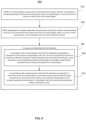
- a first electronic device and a second electronic device may be communicatively linked in a multi-user communication session.
- the first electronic device may present a three-dimensional environment including a first shared object and an avatar corresponding to a user of the second electronic device.
- the first electronic device may receive a first input.
- the first electronic device in accordance with a determination that the first input corresponds to movement of the avatar corresponding to the user of the second electronic device, the first electronic device may move the avatar and the first shared object in the three-dimensional environment in accordance with the first input.
- the first electronic device in accordance with a determination that the first input corresponds to movement of the first shared object, the first electronic device may move the first shared object in the three-dimensional environment in accordance with the first input without moving the avatar corresponding to the user of the second electronic device.
- Some examples of the disclosure are directed to systems and methods for spatial placement of avatars in a multi-user communication session.
- the first electronic device may receive an input corresponding to a request to enter a multi-user communication session with a second electronic device.
- the first electronic device may scan an environment surrounding the first electronic device to generate an occupancy map identifying locations of objects and/or open space in the environment.
- the first electronic device may identify a placement location in the three-dimensional environment at which to display a virtual object representing a user of the second electronic device.
- the placement location may be a location that is at a center of a field of view of a user of the first electronic device and/or that is a predefined distance from a viewpoint of the user of the first electronic device.
- the first electronic device in accordance with a determination that the identified placement location satisfies a first set of criteria, displays the virtual object representing the user of the second electronic device at the placement location in the three-dimensional environment, and thus enters the multi-user communication session with the second electronic device.
- the first set of criteria includes a first criterion that is satisfied when the identified placement location does not contain any objects.
- the first electronic device in accordance with a determination that the identified placement location does not satisfy the first set of criteria because the identified placement location contains an object, the first electronic device identifies an updated placement location in the three-dimensional environment presented at the first electronic device.
- the updated placement location may be a location that does not contain any objects in the three-dimensional environment.
- the first electronic device displays the virtual object representing the user of the second electronic device at the updated placement location in the three-dimensional environment.
- a first electronic device and a second electronic device may be communicatively linked in a multi-user communication session.
- the first electronic device may present a three-dimensional environment including a first shared object and an avatar corresponding to a user of the second electronic device.
- the first electronic device may receive a first input.
- the first electronic device in accordance with a determination that the first input corresponds to movement of the avatar corresponding to the user of the second electronic device, the first electronic device may move the avatar and the first shared object in the three-dimensional environment in accordance with the first input.
- the first electronic device in accordance with a determination that the first input corresponds to movement of the first shared object, the first electronic device may move the first shared object in the three-dimensional environment in accordance with the first input without moving the avatar corresponding to the user of the second electronic device.
- performing spatial placement for a multi-communication session and/or spatial refinement in the three-dimensional environment while in the multi-user communication session may include interaction with one or more objects in the three-dimensional environment.
- initiation of spatial placement for the multi-user communication session in the three-dimensional environment can include selection of one or more user interface elements.
- initiation of spatial refinement in the three-dimensional environment can include interaction with one or more virtual objects displayed in the three-dimensional environment.
- a user's gaze may be tracked by the electronic device as an input for targeting a selectable option/affordance within a respective user interface element when initiating scene placement of the multi-user communication session in the three-dimensional environment.
- gaze can be used to identify one or more options/affordances targeted for selection using another selection input.
- a respective option/affordance may be selected using hand-tracking input detected via an input device in communication with the electronic device.
- gaze can be used to identify one or more virtual objects targeted for selection when initiating spatial refinement while in the multi-user communication session.
- objects displayed in the three-dimensional environment may be moved and/or reoriented in the three-dimensional environment in accordance with movement input detected via the input device.
- FIG. 1 illustrates an electronic device 101 presenting an extended reality (XR) environment (e.g., a computer-generated environment) according to some examples of the disclosure.
- electronic device 101 is a hand-held or mobile device, such as a tablet computer, laptop computer, smartphone, or head-mounted display. Examples of device 101 are described below with reference to the architecture block diagram of FIG. 2 .
- electronic device 101, table 106, and coffee mug 152 are located in the physical environment 100.
- electronic device 101 may be configured to capture images of physical environment 100 including table 106 and coffee mug 152 (illustrated in the field of view of electronic device 101).
- the electronic device 101 may be configured to display a virtual object 114 (e.g., two-dimensional virtual content) in the computer-generated environment (e.g., represented by a rectangle illustrated in FIG. 1 ) that is not present in the physical environment 100, but is displayed in the computer-generated environment positioned on (e.g., anchored to) the top of a computer-generated representation 106' of real-world table 106.
- virtual object 114 can be displayed on the surface of the computer-generated representation 106' of the table in the computer-generated environment next to the computer-generated representation 152' of real-world coffee mug 152 displayed via device 101 in response to detecting the planar surface of table 106 in the physical environment 100.
- virtual object 110 is a representative virtual object and one or more different virtual objects (e.g., of various dimensionality such as two-dimensional or three-dimensional virtual objects) can be included and rendered in a three-dimensional computer-generated environment.
- the virtual object can represent an application or a user interface displayed in the computer-generated environment.
- the virtual object can represent content corresponding to the application and/or displayed via the user interface in the computer-generated environment.
- the virtual object 114 is optionally configured to be interactive and responsive to user input, such that a user may virtually touch, tap, move, rotate, or otherwise interact with, the virtual object.
- the virtual object 114 may be displayed in a three-dimensional computer-generated environment within a multi-user communication session ("multi-user communication session," "communication session”).
- the virtual object 114 may be viewable and/or configured to be interactive and responsive to multiple users and/or user input provided by multiple users, respectively, represented by virtual representations (e.g., avatars, such as avatar 115).
- virtual representations e.g., avatars, such as avatar 115.
- the 3D environment (or 3D virtual object) described herein may be a representation of a 3D environment (or three-dimensional virtual object) projected or presented at an electronic device.
- an electronic device that is in communication with a display generation component and one or more input devices is described. It should be understood that the electronic device optionally is in communication with one or more other physical user-interface devices, such as touch-sensitive surface, a physical keyboard, a mouse, a joystick, a hand tracking device, an eye tracking device, a stylus, etc. Further, as described above, it should be understood that the described electronic device, display and touch-sensitive surface are optionally distributed amongst two or more devices. Therefore, as used in this disclosure, information displayed on the electronic device or by the electronic device is optionally used to describe information outputted by the electronic device for display on a separate display device (touch-sensitive or not).
- input received on the electronic device e.g., touch input received on a touch-sensitive surface of the electronic device, or touch input received on the surface of a stylus
- input received on a separate input device from which the electronic device receives input information.
- the device typically supports a variety of applications, such as one or more of the following: a drawing application, a presentation application, a word processing application, a website creation application, a disk authoring application, a spreadsheet application, a gaming application, a telephone application, a video conferencing application, an e-mail application, an instant messaging application, a workout support application, a photo management application, a digital camera application, a digital video camera application, a web browsing application, a digital music player application, a television channel browsing application, and/or a digital video player application.
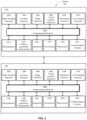
- FIG. 2 illustrates a block diagram of an exemplary architecture for a system 201 according to some examples of the disclosure.
- system 201 includes multiple devices.
- the system 201 includes a first electronic device 260 and a second electronic device 270, wherein the first electronic device 260 and the second electronic device 270 are in communication with each other.
- the first electronic device 260 and the second electronic device 270 are a portable device, such as a mobile phone, smart phone, a tablet computer, a laptop computer, an auxiliary device in communication with another device, etc., respectively.
- the first device 260 optionally includes various sensors (e.g., one or more hand tracking sensor(s) 202A, one or more location sensor(s) 204A, one or more image sensor(s) 206A, one or more touch-sensitive surface(s) 209A, one or more motion and/or orientation sensor(s) 210A, one or more eye tracking sensor(s) 212A, one or more microphone(s) 213A or other audio sensors, etc.), one or more display generation component(s) 214A, one or more speaker(s) 216A, one or more processor(s) 218A, one or more memories 220A, and/or communication circuitry 222A.
- various sensors e.g., one or more hand tracking sensor(s) 202A, one or more location sensor(s) 204A, one or more image sensor(s) 206A, one or more touch-sensitive surface(s) 209A, one or more motion and/or orientation sensor(s) 210A, one or more eye tracking sensor(s)
- the second device 270 optionally includes various sensors (e.g., one or more hand tracking sensor(s) 202B, one or more location sensor(s) 204B, one or more image sensor(s) 206B, one or more touch-sensitive surface(s) 209B, one or more motion and/or orientation sensor(s) 210B, one or more eye tracking sensor(s) 212B, one or more microphone(s) 213B or other audio sensors, etc.), one or more display generation component(s) 214B, one or more speaker(s) 216, one or more processor(s) 218B, one or more memories 220B, and/or communication circuitry 222B.
- various sensors e.g., one or more hand tracking sensor(s) 202B, one or more location sensor(s) 204B, one or more image sensor(s) 206B, one or more touch-sensitive surface(s) 209B, one or more motion and/or orientation sensor(s) 210B, one or more eye tracking sensor(s) 212
- One or more communication buses 208A and 208B are optionally used for communication between the above-mentioned components of devices 260 and 270, respectively.
- First device 260 and second device 270 optionally communicate via a wired or wireless connection (e.g., via communication circuitry 222A-222B) between the two devices.
- Communication circuitry 222A, 222B optionally includes circuitry for communicating with electronic devices, networks, such as the Internet, intranets, a wired network and/or a wireless network, cellular networks, and wireless local area networks (LANs).
- Communication circuitry 222A, 222B optionally includes circuitry for communicating using near-field communication (NFC) and/or short-range communication, such as Bluetooth ® .
- NFC near-field communication
- Bluetooth ® short-range communication
- Processor(s) 218A, 218B include one or more general processors, one or more graphics processors, and/or one or more digital signal processors.
- memory 220A, 220B is a non-transitory computer-readable storage medium (e.g., flash memory, random access memory, or other volatile or non-volatile memory or storage) that stores computer-readable instructions configured to be executed by processor(s) 218A, 218B to perform the techniques, processes, and/or methods described below.
- memory 220A, 220B can include more than one non-transitory computer-readable storage medium.
- a non-transitory computer-readable storage medium can be any medium (e.g., excluding a signal) that can tangibly contain or store computer-executable instructions for use by or in connection with the instruction execution system, apparatus, or device.
- the storage medium is a transitory computer-readable storage medium.
- the storage medium is a non-transitory computer-readable storage medium.
- the non-transitory computer-readable storage medium can include, but is not limited to, magnetic, optical, and/or semiconductor storages. Examples of such storage include magnetic disks, optical discs based on CD, DVD, or Blu-ray technologies, as well as persistent solid-state memory such as flash, solid-state drives, and the like.
- display generation component(s) 214A, 214B include a single display (e.g., a liquid-crystal display (LCD), organic light-emitting diode (OLED), or other types of display).
- display generation component(s) 214A, 214B includes multiple displays.
- display generation component(s) 214A, 214B can include a display with touch capability (e.g., a touch screen), a projector, a holographic projector, a retinal projector, etc.
- devices 260 and 270 include touch-sensitive surface(s) 209A and 209B, respectively, for receiving user inputs, such as tap inputs and swipe inputs or other gestures.
- display generation component(s) 214A,214B and touch-sensitive surface(s) 209A, 209B form touch-sensitive display(s) (e.g., a touch screen integrated with devices 260 and 270, respectively, or external to devices 260 and 270, respectively, that is in communication with devices 260 and 270).
- touch-sensitive display(s) e.g., a touch screen integrated with devices 260 and 270, respectively, or external to devices 260 and 270, respectively, that is in communication with devices 260 and 270.
- Image sensors 260 and 270 optionally includes image sensor(s) 206A and 206B, respectively.
- Image sensors(s) 206A/206B optionally include one or more visible light image sensors, such as charged coupled device (CCD) sensors, and/or complementary metal-oxide-semiconductor (CMOS) sensors operable to obtain images of physical objects from the real-world environment.
- Image sensor(s) 206A/206B also optionally include one or more infrared (IR) sensors, such as a passive or an active IR sensor, for detecting infrared light from the real-world environment.
- IR infrared
- an active IR sensor includes an IR emitter for emitting infrared light into the real-world environment.
- Image sensor(s) 206A/206B also optionally include one or more cameras configured to capture movement of physical objects in the real-world environment.
- Image sensor(s) 206A/206B also optionally include one or more depth sensors configured to detect the distance of physical objects from device 260/270.
- information from one or more depth sensors can allow the device to identify and differentiate objects in the real-world environment from other objects in the real-world environment.
- one or more depth sensors can allow the device to determine the texture and/or topography of objects in the real-world environment.
- devices 260 and 270 use CCD sensors, event cameras, and depth sensors in combination to detect the physical environment around devices 260 and 270.
- image sensor(s) 206A/206B include a first image sensor and a second image sensor. The first image sensor and the second image sensor work in tandem and are optionally configured to capture different information of physical objects in the real-world environment.
- the first image sensor is a visible light image sensor and the second image sensor is a depth sensor.
- device 260/270 uses image sensor(s) 206A/206B to detect the position and orientation of device 260/270 and/or display generation component(s) 214A/214B in the real-world environment.
- device 260/270 uses image sensor(s) 206A/206B to track the position and orientation of display generation component(s) 214A/214B relative to one or more fixed objects in the real-world environment.
- device 260/270 includes microphone(s) 213A/213B or other audio sensors. Device 260/270 uses microphone(s) 213A/213B to detect sound from the user and/or the real-world environment of the user. In some embodiments, microphone(s) 213A/213B includes an array of microphones (a plurality of microphones) that optionally operate in tandem, such as to identify ambient noise or to locate the source of sound in space of the real-world environment.
- Device 260/270 includes location sensor(s) 204A/204B for detecting a location of device 260/270 and/or display generation component(s) 214A/214B.
- location sensor(s) 204A/204B can include a GPS receiver that receives data from one or more satellites and allows device 260/270 to determine the device's absolute position in the physical world.
- Device 260/270 includes orientation sensor(s) 210A/210B for detecting orientation and/or movement of device 260/270 and/or display generation component(s) 214A/214B.
- device 260/270 uses orientation sensor(s) 210A/210B to track changes in the position and/or orientation of device 260/270 and/or display generation component(s) 214A/214B, such as with respect to physical objects in the real-world environment.
- Orientation sensor(s) 210A/210B optionally include one or more gyroscopes and/or one or more accelerometers.
- Device 260/270 includes hand tracking sensor(s) 202A/202B and/or eye tracking sensor(s) 212A/212B, in some embodiments.
- Hand tracking sensor(s) 202A/202B are configured to track the position/location of one or more portions of the user's hands, and/or motions of one or more portions of the user's hands with respect to the extended reality environment, relative to the display generation component(s) 214A/214B, and/or relative to another defined coordinate system.
- Eye tracking sensor(s) 212A/212B are configured to track the position and movement of a user's gaze (eyes, face, or head, more generally) with respect to the real-world or extended reality environment and/or relative to the display generation component(s) 214A/214B.
- hand tracking sensor(s) 202A/202B and/or eye tracking sensor(s) 212A/212B are implemented together with the display generation component(s) 214A/214B. In some embodiments, the hand tracking sensor(s) 202A/202B and/or eye tracking sensor(s) 212A/212B are implemented separate from the display generation component(s) 214A/214B.
- the hand tracking sensor(s) 202A/202B can use image sensor(s) 206A/206B (e.g., one or more IR cameras, 3D cameras, depth cameras, etc.) that capture three-dimensional information from the real-world including one or more hands (e.g., of a human user).
- the hands can be resolved with sufficient resolution to distinguish fingers and their respective positions.
- one or more image sensor(s) 206A/206B are positioned relative to the user to define a field of view of the image sensor(s) 206A/206B and an interaction space in which finger/hand position, orientation and/or movement captured by the image sensors are used as inputs (e.g., to distinguish from a user's resting hand or other hands of other persons in the real-world environment). Tracking the fingers/hands for input (e.g., gestures, touch, tap, etc.) can be advantageous in that it does not require the user to touch, hold or wear any sort of beacon, sensor, or other marker.
- eye tracking sensor(s) 212A/212B includes at least one eye tracking camera (e.g., infrared (IR) cameras) and/or illumination sources (e.g., IR light sources, such as LEDs) that emit light towards a user's eyes.
- the eye tracking cameras may be pointed towards a user's eyes to receive reflected IR light from the light sources directly or indirectly from the eyes.
- both eyes are tracked separately by respective eye tracking cameras and illumination sources, and a focus/gaze can be determined from tracking both eyes.
- one eye e.g., a dominant eye
- Device 260/270 and system 201 are not limited to the components and configuration of FIG. 2 , but can include fewer, other, or additional components in multiple configurations.
- system 201 can be implemented in a single device.
- a person or persons using system 201, is optionally referred to herein as a user or users of the device(s).
- first electronic device e.g., corresponding to device 260
- second electronic device e.g., corresponding to device 270
- the first electronic device may be in communication with the second electronic device in a multi-user communication session.
- an avatar e.g., a representation of
- a user of the first electronic device may be displayed in the three-dimensional environment at the second electronic device
- an avatar of a user of the second electronic device may be displayed in the three-dimensional environment at the first electronic device.
- content may be shared within the three-dimensional environment while the first electronic device and the second electronic device are in the multi-user communication session.
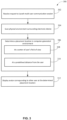
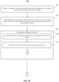
- FIG. 3 illustrates a flow diagram illustrating an example process 300 of facilitating spatial placement for an avatar in a multi-user communication session in a computer-generated environment according to some examples of the disclosure.
- a plurality of electronic devices may present a shared three-dimensional environment which may include one or more shared virtual objects, one or more unshared virtual objects (e.g., representations thereof), and/or three-dimensional representations (e.g., renderings) of users of the plurality of electronic devices.
- a user may initiate a multi-user communication session with one or more remote electronic devices, which optionally includes placement of one or more three-dimensional representations of users of the one or more remote electronic devices within the three-dimensional environment presented at the first electronic device.
- the example processes shown in FIG. 3 and described below will be exemplified and described in more detail when referring to FIGs. 4A-4I below.
- the first electronic device may receive a request to launch a multi-user communication session with one or more remote electronic devices, at 302.
- the user of the first electronic device may provide user input at the first electronic device corresponding to a request to enter the multi-user communication session with a second electronic device.
- the first electronic device may scan a physical environment surrounding the first electronic device, at 304.
- the first electronic device may be located within a physical room containing one or more physical objects (e.g., chairs, tables, sofas, lamps, etc.).
- the first electronic device may generate an occupancy map of the portions of the physical environment that are within a field of view of the user of the first electronic device (e.g., portions of the physical environment that are visible to the user due to the presence of the display blocking the user's view of the physical environment around the user).
- the occupancy map optionally identifies unique locations of the physical objects that are within the user's field of view.
- the first electronic device may scan the three-dimensional environment within the field of view of the user of the first electronic device.
- the three-dimensional environment within the field of view of the user of the first electronic device may include one or more virtual objects (e.g., three-dimensional application windows, three-dimensional and/or two-dimensional content, virtual models, three-dimensional representations of physical objects, etc.).
- the occupancy map generated by the first electronic device optionally identifies unique locations of the virtual objects that are within the user's field of view.
- the one or more remote electronic devices that are joining the multi-user communication session with the first electronic device optionally also scan the physical and/or three-dimensional environments surrounding the one or more remote electronic devices.
- the first electronic device and the second electronic device each individually scan the physical environments respectively surrounding the first electronic device and the second electronic device, at 304, to generate occupancy maps based on locations of objects in the field of view of the users of the first electronic device and the second electronic device, respectively.
- the first electronic device and the second electronic device may each determine a placement location in the three-dimensional environment at which to spatially place an avatar corresponding to the user of the other electronic device in the multi-user communication session, at 306.
- the first electronic device determines a placement location at which to place an avatar corresponding to the user of the second electronic device
- the second electronic device determines a placement location at which to place an avatar corresponding to the user of the first electronic device.
- determining the placement location includes determining a location in the three-dimensional environment that is at a center of the user's field of view, at 308.
- the first electronic device identifies a location in the three-dimensional environment presented at the first electronic device that is at or near (e.g., within a threshold distance of, such as 0.1, 0.5, 1, 1.5, 2, 3, 5, etc. meters (m), or some other unit of distance) the center of the field of view of the user of the first electronic device.
- the second electronic device identifies a location in the three-dimensional environment presented at the second electronic device that is at or near the center of the field of view of the user of the second electronic device.
- determining the placement location includes determining a location in the three-dimensional environment that is at a predefined distance from a viewpoint of the user (e.g., a perspective from which the user experiences the three-dimensional environment), at 310.
- the first electronic device identifies a location in the three-dimensional environment presented at the first electronic device that is a predefined distance (e.g., 1, 1.2, 1.4, 1.5, 2, 2.5, etc. m) from the viewpoint of the user of the first electronic device.
- the second electronic device identifies a location in the three-dimensional environment presented at the second electronic device that is the predefined distance from the viewpoint of the user of the second electronic device.
- the placement location is determined based on the center of the user's field of view and the predefined distance from the viewpoint of the user.
- the determination of the placement location is in accordance with the satisfaction of a first set of criteria.
- the first electronic device and the second electronic device may each generate an occupancy map that identifies locations of physical and/or virtual objects that are within the field of view of the users of the first electronic device and the second electronic device, respectively.
- the first set of criteria includes a first criterion that is satisfied when the placement location does not contain an object (e.g., a physical object or a virtual object).
- the first electronic device and the second electronic device may each utilize their respective occupancy map generated by scanning the respective environments within the field of views of the first electronic device and the second electronic device to determine whether the first criterion is satisfied.
- the placement location may be updated (e.g., modified) to instead be a location in the three-dimensional environment, different from the center of the field of view of the user and/or the predefined distance from the viewpoint of the user, that does not contain an object.
- the determined placement location is optionally provided as a suggestion (e.g., displayed as a visual element, such as a virtual pin) to the user and the user can confirm or change the placement location (e.g., by selecting and moving the visual element).
- a distance between the selected placement location and the viewpoint of the initiating user is used as the distance between the viewpoint of the other user and the placement location at the other user's electronic device, or vice versa, as described in more detail herein later.
- the other user has the option to move the placement location radially around their respective viewpoint at the defined distance to maintain spatial truth between the viewpoints of the users (e.g., because spatial truth requires the same offset distance, but radial changes to the placement location relative to the user can be accommodated by causing the other user's avatar to turn/orient in the corresponding direction, as discussed herein).
- the first electronic device may enter the multi-user communication session with the one or more remote electronic devices, which includes displaying an avatar corresponding to the user(s) of the other electronic device(s) at the determined placement location(s) in the three-dimensional environment, at 312.
- the first electronic device may display the avatar corresponding to the user of the second electronic device at the determined placement location in the three-dimensional environment presented at the first electronic device.
- the second electronic device may display the avatar corresponding to the user of the first electronic device at the determined placement location in the three-dimensional environment presented at the second electronic device.
- the avatars corresponding to the users of the first electronic device and the second electronic device are located the predefined distance (e.g., 1.5m) away from each other in the three-dimensional environment shared between the first electronic device and the second electronic device.
- the placement of the avatars corresponding to the users of the first electronic device and the second electronic device optionally maintains spatial truth in the shared three-dimensional environment (e.g., maintains consistent spatial relationships between viewpoints of users and shared virtual content at each electronic device), such that the avatar corresponding to the user of the second electronic device is the predefined distance from the viewpoint of the user of the first electronic device, and the avatar corresponding to the user of the first electronic device is the predefined distance from the viewpoint of the user of the second electronic device.
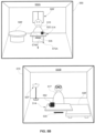
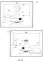
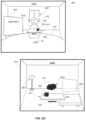
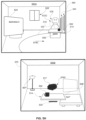
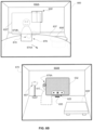
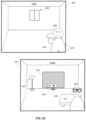
- FIGs. 4A-4I illustrate example processes of spatial placement for avatars in a multi-user communication session according to some examples of the disclosure.
- a first electronic device 460 may present a three-dimensional environment 450A
- a second electronic device 470 may present a three-dimensional environment 450B.
- the first electronic device 460 and the second electronic device 470 may be similar to device 101 or 260/270, and/or may be a head mountable system/device and/or projection-based system/device (including a hologram-based system/device) configured to generate and present a three-dimensional environment, such as, for example, heads-up displays (HUDs), head mounted displays (HMDs), windows having integrated display capability, displays formed as lenses designed to be placed on a person's eyes (e.g., similar to contact lenses), respectively.
- HUDs heads-up displays
- HMDs head mounted displays
- windows having integrated display capability displays formed as lenses designed to be placed on a person's eyes (e.g., similar to contact lenses), respectively.
- a first user is optionally wearing the electronic device 460 and a second user is optionally wearing the electronic device 470, such that the three-dimensional environments 450A/450B can be defined by X, Y and Z axes as viewed from a perspective of the electronic devices (e.g., a viewpoint associated with the users of the electronic devices 460/470).
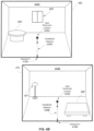
- the electronic device 460 may be in a first physical environment that includes a table 406 and a window 409.
- the three-dimensional environment 450A presented using the electronic device 460 optionally includes captured portions of the physical environment surrounding the electronic device 460, such as a representation of the table 406' and a representation of the window 409'.
- the electronic device 470 may be in a second physical environment, different from the first physical environment (e.g., separate from the first physical environment), that includes a floor lamp 407 and a coffee table 408.
- the three-dimensional environment 450B presented using the electronic device 470 optionally includes captured portions of the physical environment surrounding the electronic device 470, such as a representation of the floor lamp 407' and a representation of the coffee table 408'. Additionally, the three-dimensional environments 450A and 450B may include representations of the floor, ceiling, and walls of the room in which the first electronic device 460 and the second electronic device 470 are located, respectively.
- the first electronic device 460 may enter a multi-user communication session with the second electronic device 470.
- the first electronic device 460 and the second electronic device 470 e.g., via communication circuitry 222A/222B
- the first electronic device 460 and the second electronic device 470 are configured to present a shared three-dimensional environment that includes one or more shared virtual objects (e.g., content such as images, video, audio and the like, representations of user interfaces of applications, etc.).
- shared three-dimensional environment refers to a three-dimensional environment that is independently presented, displayed, and/or visible at two or more electronic devices via which content, applications, data, and the like may be shared and/or presented to users of the two or more electronic devices.
- the user of the first electronic device 460 may provide input at the first electronic device 460 corresponding to a request to launch a multi-user communication session with one or more remote electronic devices (e.g., such as the second electronic device 470).
- the three-dimensional environment 450A optionally includes a plurality of virtual objects 410, which optionally correspond to (e.g., two-dimensional or three-dimensional) representations of icons associated with respective applications that may be launched at electronic device 460.
- the plurality of virtual objects 410 includes a first virtual object 410A, which optionally corresponds to a representation of an icon associated with a communications application that may be launched at the first electronic device 460.
- the virtual object 410A may be activated in three-dimensional environment 450A to cause the electronic device 460 to launch a multi-user communication session with one or more remote electronic devices (e.g., such as the second electronic device 470).
- selection of the virtual object 410A enables the user of the first electronic device 460 to identify/designate (e.g., select via a user interface associated with the communications application) the one or more remote electronic devices as invitees to join the multi-user communication session with the first electronic device 460.
- the user of the first electronic device 460 has optionally chosen the user of the second electronic device 470 as the invitee for joining the multi-user communication session with the user of the first electronic device 460.
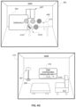
- the user of the first electronic device 460 is optionally providing a selection input 472A directed to the first virtual object 410A.
- the user may provide a pinch input (e.g., in which the index finger and the thumb of the hand of the user make contact) while the gaze of the user is directed toward the first virtual object 410A (or other suitable input such as a tap input, gaze for more than a threshold period of time, etc.).
- the second electronic device 470 in response to receiving the selection input 472A directed to the first virtual object 410A, the second electronic device 470 optionally receives an indication of a request from the first electronic device 460 to enter the multi-user communication session with the first electronic device 460. For example, as shown in FIG.
- the second electronic device 470 in response to receiving the indication from the first electronic device 460, the second electronic device 470 optionally displays a first user interface element 418 (e.g., a notification) corresponding to the request to enter the multi-communication session with the first electronic device 460.
- the first user interface element 418 includes an option 419A that is selectable to accept the invitation, and thus initiate a process to launch a multi-user communication session between the first electronic device 460 and the second electronic device 470.
- launching the multi-user communication session between the first electronic device 460 and the second electronic device 470 includes identifying a suitable placement location within the three-dimensional environments 450A/450B at which to place the avatars corresponding to the users of the first electronic device 460 and the second electronic device 470.
- the first electronic device optionally identifies a suitable placement location within the three-dimensional environment 450A at which to place an avatar corresponding to the user of the second electronic device 470
- the second electronic device optionally identifies a placement location within the three-dimensional environment 450B at which to place an avatar corresponding to the user of the first electronic device 460.
- the three-dimensional environment optionally includes avatars corresponding to the users of the electronic devices that are in the communication session, wherein the avatars provide spatial reference points of relative distances and orientations between virtual locations of users within the shared environment of the multi-user communication session.
- the physical environment surrounding a respective electronic device may contain physical objects that are within the field of view of a user of the respective electronic device.
- Placement of avatars at locations within the three-dimensional environment that are occupied by physical (and/or virtual) objects may cause portions of the avatars to be obscured, cut-off, or otherwise appear unrealistic from the viewpoints of the users of the electronic devices in the multi-user communication session.
- allowing users to manually select placement locations for avatars in the shared three-dimensional environment in the multi-user communication session may avoid placement of avatars in locations that intersect physical objects, but coordinating such placement locations among multiple users may increase the cognitive burden for the users.
- the electronic devices may automatically select placement locations at which to display the avatars that avoid physical and/or virtual objects within the field of view of the users and that maintain spatial consistency between the users of the electronic devices.
- the first electronic device 460 and the second electronic device 470 may scan the physical environments surrounding the first electronic device 460 and the second electronic device 470. For example, as described previously with reference to FIG. 3 , the first electronic device 460 and the second electronic device 470 may each scan the physical environments within the field of view of the electronic device (e.g., via image sensors 206A/206B in FIG. 2 ) to generate an occupancy map at each electronic device.
- the occupancy map may identify locations within the field of view of an electronic device that contain objects and that do not contain objects.
- the first electronic device 460 and the second electronic device 470 may utilize the occupancy map to determine a placement location for each of the avatars corresponding to the users of the first electronic device 460 and the second electronic device 470.
- the first electronic device 460 optionally determines a first preferred placement location 425A within three-dimensional environment 450A
- the second electronic device 470 optionally determines a second preferred placement location 425B within three-dimensional environment 450B.
- determining the placement location for the avatars includes identifying a location that is at or near a center of the field of view of the user and/or that is a predetermined distance from a viewpoint of the user.
- a preferred placement location is a location that is at the center of the field of view of the user of an electronic device and that is at the predetermined distance from the viewpoint of the user. For example, as shown in FIG.
- the determined first placement location 425A within three-dimensional environment 450A is at a center of the field of view of the user of the first electronic device 460, and is a predefined distance (e.g., 1, 1.2, 1.4, 1.5, 2, 2.5, etc. m) 426A away from a viewpoint 418A of the user of the first electronic device 460.
- the determined second placement location 425B within three-dimensional environment 450B is at a center of the field of view of the user of the second electronic device 470, and is the predefined distance 426B away from the viewpoint 418B of the user of the second electronic device 470.
- the predefined distance 426A at the first electronic device 460 is optionally equal to the predefined distance 426B at the second electronic device 470.
- the electronic devices 460/470 after the electronic devices 460/470 determine preferred placement locations for the avatars corresponding to the users of the electronic devices 460/470, the electronic devices 460/470 optionally evaluate whether the identified placement locations satisfy a first set of criteria.
- the first set of criteria optionally includes a first criterion that is satisfied when the identified placement location is not occupied by an object (e.g., a virtual or physical object).
- the first electronic device 460 and the second electronic device 470 may utilize each of their generated occupancy maps to determine whether the identified placement locations satisfy the first set of criteria. For example, with reference to FIG.
- the identified placement location 425A within three-dimensional environment 450A at the first electronic device 460 does not contain an object
- the identified placement location 425A satisfies the first set of criteria.
- the identified placement location 425B within three-dimensional environment 450B at the second electronic device 470 does not contain an object
- the identified placement location 425B satisfies the first set of criteria.
- the first electronic device 460 and the second electronic device 470 may proceed to displaying the avatars corresponding to the users of the first electronic device 460 and the second electronic device 470 at the identified placement locations in the three-dimensional environments 450A/450B.
- the first electronic device 460 optionally displays an avatar 415 corresponding to the user of the second electronic device 470 at the first placement location 425A within the three-dimensional environment 450A.
- the second electronic device 470 optionally displays an avatar 417 corresponding to the user of the first electronic device 460 at the second placement location 425B within the three-dimensional environment 450B.
- the avatar 415 corresponding to the user of the second electronic device 470 may be displayed the predefined distance 426A from the viewpoint 418A of the user of the first electronic device 460
- the avatar 417 corresponding to the user of the first electronic device 460 may be displayed the predefined distance 426B from the viewpoint 418B of the user of the second electronic device 470.
- the predefined distance 426A at the first electronic device 460 and the predefined distance 426B at the second electronic device 470 may be equal.
- the predefined distances 425A/425B are both values between 1m-1.5m
- the avatar 415 is optionally a value between 1m - 1.5m from the viewpoint of the user of the first electronic device 460
- the avatar 417 is also optionally the same value between 1m - 1.5m from the viewpoint of the user of the second electronic device 470.
- the avatars corresponding to the users of the electronic devices 460/470 maintain spatial truth within their respective three-dimensional environments 450A/450B at the initiation of the multi-user communication session between the first electronic device 460 and the second electronic device 470.
- the first electronic device 460 and the second electronic device 470 are communicatively linked in the multi-user communication session.
- the presentation of avatars 415/417 as part of the shared three-dimensional environment is optionally accompanied by an audio effect corresponding to a voice of the users of the electronic devices 470/460.
- the avatar 415 displayed in the three-dimensional environment 450A using the first electronic device 460 is optionally accompanied by an audio effect corresponding to the voice of the user of the second electronic device 470.
- the voice of the user may be detected by the second electronic device 470 (e.g., via the microphone(s) 213B) and transmitted to the first electronic device 460 (e.g., via the communication circuitry 222B/222A), such that the detected voice of the user of the second electronic device 470 may be presented as audio (e.g., using speaker(s) 216A) to the user of the first electronic device 460 in three-dimensional environment 450A.
- the avatar 417 displayed in the three-dimensional environment 450B using the second electronic device 470 is optionally accompanied by an audio effect corresponding to the voice of the user of the first electronic device 460.
- the voice of the user may be detected by the first electronic device 460 (e.g., via the microphone(s) 213A) and transmitted to the second electronic device 470 (e.g., via the communication circuitry 222A/222B), such that the detected voice of the user of the first electronic device 460 may be presented as audio (e.g., using speaker(s) 216B) to the user of the second electronic device 470 in three-dimensional environment 450B.
- the avatars 415/417 are displayed in the three-dimensional environments 450A/450B with respective orientations that correspond to and/or are based on orientations of the electronic devices 460/470 in the physical environments surrounding the electronic devices 460/470.
- the avatar 415 is optionally facing toward the viewpoint (e.g., viewpoint 418A) of the user of the first electronic device 460
- the avatar 417 is optionally facing toward the viewpoint (e.g., viewpoint 418B) of the user of the second electronic device 470.
- the viewpoint of the user changes in accordance with the movement, which may thus also change an orientation of the user's avatar in the three-dimensional environment.
- the user of the first electronic device 460 were to look leftward in the three-dimensional environment 450A such that the first electronic device 460 is rotated (e.g., a corresponding amount) to the left (e.g., counterclockwise)
- the user of the second electronic device 470 would see the avatar 417 corresponding to the user of the first electronic device 460 rotate to the right (e.g., clockwise) in accordance with the movement of the first electronic device 460.
- a viewpoint of the three-dimensional environments 450A/450B and/or a location of the viewpoint of the three-dimensional environments 450A/450B optionally changes in accordance with movement of the electronic devices 450A/450B (e.g., by the users of the electronic devices 450A/450B).
- the viewpoint e.g., viewpoint 418A
- the representation of the table 406', the representation of the window 409' and the avatar 415 appear larger in the field of view of three-dimensional environment 450A.
- the avatars 415/417 are a representation (e.g., a full-body rendering) of each of the users of the electronic devices 470/460.
- the avatars 415/417 are each a representation of a portion (e.g., a rendering of a head, face, head and torso, etc.) of the users of the electronic devices 470/460.
- the avatars 415/417 are a user-personalized, user-selected, and/or user-created representation displayed in the three-dimensional environments 450A/450B that is representative of the users of the electronic devices 470/460. It should be understood that, while the avatars 415/417 illustrated in FIG. 4C correspond to simplified representations of a full body of each of the users of the electronic devices 470/460, respectively, alternative avatars may be provided, such as those described above.
- more than two electronic devices may be communicatively linked in a multi-user communication session.
- a first electronic device would display two avatars, rather than just one avatar, corresponding to the users of the other two electronic devices.
- the various processes and exemplary interactions described herein with reference to initializing and facilitating a multi-user communication session between the first electronic device 460 and the second electronic device 470 optionally apply to situations in which more than two electronic devices are communicatively linked in a multi-user communication session.
- the electronic devices optionally scan the environments surrounding each electronic device, respectively, to generate an occupancy map at each electronic device.
- the spatial arrangement for placement of the avatars corresponding to the users of the electronic devices may be determined based on the occupancy maps generated by the electronic devices.
- an alternative placement arrangement may be utilized when placing the avatars corresponding to the users of the electronic devices in the three-dimensional environment.
- the electronic devices may adopt a circular/oval-shaped (or some other shape) placement arrangement, such that the avatars corresponding to the users of the electronic device are displayed in a circular/oval-shaped (or some other shape) in the three-dimensional environment.
- the electronic devices may utilize the generated occupancy maps to identify placement locations (e.g., points) along the circle/oval (or other shape) at which to place the avatars.
- the identified first placement location 425A and/or the identified second placement location 425B may not satisfy the first set of criteria described above.
- the identified first placement location 425A and/or the identified second placement location 425B may contain one or more objects (e.g., physical and/or virtual objects), which optionally fails to satisfy the first set of criteria.
- the first electronic device 460 and/or the second electronic device 470 may alter the placement location within the three-dimensional environment and identify one or more candidate placement locations that satisfy the first set of criteria.
- the first electronic device 460 may present the three-dimensional environment 450A, which optionally includes the plurality of virtual objects 410, as similarly described above with reference to FIG. 4A .
- the three-dimensional environment 450B may include representations of the captured portions of the physical environment surrounding the first electronic device 460, such as the representation of the table 406' and the representation of the window 409'.
- the representation of the table 406' is optionally located behind the plurality of virtual objects 410.
- the second electronic device 470 may present the three-dimensional environment 450B, which optionally includes representations of the captured portions of the physical environment surrounding the second electronic device, such as the representation of the floor lamp 407' and the representation of the coffee table 408'.
- the user of the first electronic device 460 may provide input at the first electronic device 460 corresponding to a request to enter a multi-user communication session with the second electronic device 470.
- the user of the first electronic device 460 may provide the selection input 472B (e.g., via a pinch gesture, a tap or touch input, a verbal command, etc.) directed to the first virtual object 410B for launching the multi-user communication session.
- the second electronic device 470 may receive an indication from the first electronic device 460 corresponding to an invitation to join the multi-user communication session with the first electronic device 460.
- the second electronic device 470 In response to receiving the indication, the second electronic device 470 optionally displays the first user interface element 418 corresponding to the invitation, which includes a selectable option 419B to accept the invitation from the first electronic device 460 and cause the second electronic device 470 join the multi-user communication session with the first electronic device 460.
- the first electronic device 460 and the second electronic device 470 may initiate launching of the multi-user communication session.
- the first electronic device 460 and the second electronic device 470 may each scan the physical environment surrounding the electronic device, to identify respective locations of physical objects and/or open space (e.g., locations not containing objects) within the field of view of the user of the electronic device.
- the first electronic device 460 may scan the physical environment surrounding the first electronic device 460 to generate an occupancy map characterizing the environment within the field of view of the user of the first electronic device 460, such as identifying locations of physical objects (e.g., the table 406) within the field of view of the user of the first electronic device 460.
- the second electronic device 470 may scan the physical environment surrounding the second electronic device 470 to generate an occupancy map characterizing the environment within the field of view of the user of the second electronic device 470, such as identifying locations of physical objects (e.g., the floor lamp 407 and/or the coffee table 408) within the field of view of the user of the second electronic device 470.
- the first electronic device 460 and the second electronic device 470 may identify a placement location within the three-dimensional environments 450A/450B at which to place an avatar corresponding to a user of the first electronic device 460 and an avatar corresponding to a user of the second electronic device 470.
- the first electronic device 460 may identify a placement location 425A that is at or near (e.g., within 0.25, 0.5, 0.8, 1, 1.5, 2, 2.5, etc.
- the identified placement location 425A within the three-dimensional environment 450A at least partially intersects with a portion of an object within the three-dimensional environment 450A, namely a front leg of the table 406 in the physical environment surrounding the first electronic device 460. Because a portion of the representation of the table 406' intersects/overlaps with the preferred placement location 425A, the first set of criteria is not satisfied. Accordingly, in some examples, the first electronic device 460 may proceed to identifying an updated/candidate placement location, different from the preferred placement location 425A, within the three-dimensional environment 450A.
- a predefined distance e.g. 1, 1.4, 1.5, 1.8, 2, 2.5, 3, etc. m
- the first electronic device 460 may utilize the occupancy map generated at the first electronic device 460 to identify an updated placement location 425C within the three-dimensional environment 450A.
- the updated placement location 425C is optionally a location that is offset (e.g., angularly by 3, 5, 10, 15, 20, 25, 30, etc. degrees) to the left of the preferred placement location 425A from the viewpoint 418A of the user of the first electronic device 460, and/or that is the predefined distance 426A from the viewpoint 418A. It should be understood that, while the relative lengths of the arrows representing the predefined distances 426A may appear to be different in FIG. 4E , the distance between the viewpoint 418A and each of the placement locations 425A and 425C are optionally the same.
- identifying an updated placement location may include altering the distance between the identified placement location (e.g., 425A) and the viewpoint (e.g., 418A) of the user of the electronic device.
- relative bounds determined by the environment surrounding the electronic device may limit the degrees to which the distance is increased or decreased. For example, as shown in FIG. 4E , at the first electronic device 460, a first bound 421A may impose a minimum distance between a candidate placement location and the viewpoint 418A of the user of the first electronic device 460. In some examples, the minimum distance may be a predetermined value (e.g., 0.5, 0.8, 1, 1.2, etc.
- a second bound 422A may impose a maximum distance between the candidate placement location and the viewpoint 418A of the user of the first electronic device 460.
- the maximum distance may be a predetermined value (e.g., 4, 4.5, 5, 7, 8, 10, etc. m), and/or may be determined based on limitations in the physical environment surrounding the electronic device. For example, the second bound 422A in FIG.
- the first electronic device 460 may be determined based on the far wall in the physical environment in the field of view of the user of the first electronic device 460, and thus may restrict how far (e.g., from the viewpoint 418A) the avatar corresponding to the user of the second electronic device is initially placed in three-dimensional environment 450A. Because an open space exists to the left of the representation of the table 406' at the predefined distance 426A, the first electronic device 460 optionally forgoes adjusting the distance between the identified placement location 425C and the viewpoint 418A. As shown in FIG. 4E , the updated placement location 425C is not occupied by any objects which satisfies the first criterion, and thus, satisfies the first set of criteria at the first electronic device 460.
- the second electronic device 470 may also identify a placement location 425B within the three-dimensional environment 450B that is at or near the center of the field of view of the user of the second electronic device 470 and/or that is the predefined distance 426B from the viewpoint 418B of the user of the second electronic device 470.
- the identified placement location 425B within the three-dimensional environment 450B is not occupied by any objects, the identified placement location 425B optionally satisfies the first criterion, and thus the first set of criteria at the second electronic device 470.
- the predefined distance 426A at the first electronic device 460 may be equal to the predefined distance 426B at the second electronic device 470.
- the first electronic device 460 and the second electronic device 470 may display avatars corresponding to the users of the first electronic device 460 and the second electronic device 470 at the identified placement locations. For example, as shown in FIG. 4F , the first electronic device 460 may place the avatar 415 corresponding to the user of the second electronic device 470 at the determined placement location 425C in three-dimensional environment 450A. Similarly, as shown, the second electronic device 470 may place the avatar 417 corresponding to the user of the first electronic device 460 at the determined placement location 425B in three-dimensional environment 450B.
- the avatar 415 corresponding to the user of the second electronic device 470 may be the predefined distance (e.g., 1.5m) from the viewpoint (e.g., viewpoint 418A) of the user of the first electronic device 460, and the avatar 417 corresponding to the user of the first electronic device 460 may be the predefined distance from the viewpoint (e.g., viewpoint 418B) of the user of the second electronic device 470.
- the avatars 415 and 417 may be displayed in three-dimensional environments 450A and 450B with respective orientations corresponding to the orientations of the electronic devices 460 and 470 presenting the three-dimensional environments 450A and 450B.
- the respective orientations of the avatars 415 and 417 may be indicative of determined placement locations that are off-center (e.g., with respect to the center of the field of view of the user of the electronic device). For example, as shown in FIG.
- the first electronic device 460 may display the avatar 415 corresponding to the user of the second electronic device 470 with an orientation that is facing toward the viewpoint (e.g., viewpoint 418A) of the user of the first electronic device 460 (e.g., illustrated by the orientation of the face of the avatar 415).
- viewpoint e.g., viewpoint 418A
- the second electronic device 470 may display the avatar 417 of the user of the first electronic device 460 with an orientation that is facing leftward relative to the viewpoint (e.g., viewpoint 418B) of the user of the second electronic device 470 (e.g., illustrated by the orientation of the face of the avatar 417), as shown.
- viewpoint 418B e.g., viewpoint 418B
- orientations of the faces of the avatars 415/417 are utilized in FIG. 4F to indicate (e.g., changes to) the respective orientations of the avatars 415/417 of the users within the three-dimensional environments 450A/450B
- additional or alternative characteristics of the avatars 415/417 may be utilized to convey changes to the respective orientations of the avatars 415/417.
- the torso e.g., including the shoulders, arms, and/or chest
- the torso may indicate the respective orientations of the avatars within the three-dimensional environments 450A/450B.
- the lower-body (e.g., including the hips, legs, and/or feet) of each of the avatars may indicate the respective orientations of the avatars within the three-dimensional environments 450A/450B.
- one advantage of the disclosed placement method for avatars in a multi-user communication session is the facilitation of automatic placement of avatars individually at each electronic device based on locations of objects in the environments surrounding the electronic devices, thereby reducing the cognitive burden on users when launching and/or operating in the multi-user communication session. Attention is now directed to an example in which objects are located at the preferred placement locations at both the first electronic device and the second electronic device, requiring spatial compromise between the first electronic device and the second electronic device, as described below.
- the first electronic device 460 may present the three-dimensional environment 450A, which optionally includes the plurality of virtual objects 410, as similarly described above with reference to FIGs. 4A and 4D .
- the three-dimensional environment 450A may include a respective user interface element 424 corresponding to a respective application (e.g., Application A) running on the first electronic device 460.
- the three-dimensional environment 450A may include representations of the captured portions of the physical environment surrounding the first electronic device 460, such as the representation of the table 406' and the representation of the window 409'. As shown in FIG.
- the representation of the table 406' is optionally located behind the plurality of virtual objects 410.
- the second electronic device 470 may present the three-dimensional environment 450B, which optionally includes representations of the captured portions of the physical environment surrounding the second electronic device, such as the representation of the floor lamp 407', the representation of the coffee table 408', and a representation of a sofa 411'.
- the user of the first electronic device 460 may provide input at the first electronic device 460 corresponding to a request to enter a multi-user communication session with the second electronic device 470.
- the user of the first electronic device 460 may provide the selection input 472C (e.g., via a pinch gesture, a tap or touch input, a verbal command, etc.) directed to the first virtual object 410C for launching the multi-user communication session.
- the second electronic device 470 may receive an indication from the first electronic device 460 corresponding to an invitation to join the multi-user communication session with the first electronic device 460.
- the second electronic device 470 In response to receiving the indication, the second electronic device 470 optionally displays the first user interface element 418 corresponding to the invitation, which includes a selectable option 419C to accept the invitation from the first electronic device 460 and cause the second electronic device 470 join the multi-user communication session with the first electronic device 460.
- the first electronic device 460 and the second electronic device 470 may initiate launching of the multi-user communication session.
- the first electronic device 460 and the second electronic device 470 may each scan the physical environment surrounding the electronic device, to identify respective locations of physical objects and/or open space (e.g., locations not containing objects) within the field of view of the user of the electronic device.
- the first electronic device 460 may scan the physical environment surrounding the first electronic device 460 to generate an occupancy map characterizing the environment within the field of view of the user of the first electronic device 460, such as identifying locations of physical objects (e.g., the table 406) within the field of view of the user of the first electronic device 460.
- the second electronic device 470 may scan the physical environment surrounding the second electronic device 470 to generate an occupancy map characterizing the environment within the field of view of the user of the second electronic device 470, such as identifying locations of physical objects (e.g., the floor lamp 407, the coffee table 408 and/or the sofa 411) within the field of view of the user of the second electronic device 470.
- generating the occupancy map at the first electronic device 460 and the second electronic device 470 may include identifying locations of virtual objects within the field of view of the user of the first electronic device 460 and that of the second electronic device 470.
- the three-dimensional environment 450A presented at the first electronic device 460 may include the respective user interface element 424 in the field of view of the user of the first electronic device 460.
- the location of the respective user interface element 424 within the three-dimensional environment 450A may be identified along with the locations of the physical objects in the field of view of the user of the first electronic device 460.
- the first electronic device 460 and the second electronic device 470 may identify a placement location within the three-dimensional environments 450A/450B at which to place the avatar corresponding to the user of the first electronic device 460 and the avatar corresponding to the user of the second electronic device 470.
- the avatar 415 corresponding to the user of the second electronic device 470 and the avatar 417 corresponding to the user of the first electronic device 460 may be placed at the identified placement locations if the identified placement locations satisfy a first set of criteria, including a first criterion that is satisfied when the identified placement locations are not occupied by any objects. For example, as similarly discussed above and as shown in FIG.
- the first electronic device 460 may identify a preferred placement location 425A that is at or near (e.g., within 0.25, 0.5, 0.8, 1, 1.5, 2, 2.5, etc. m of) the center of the field of view of the user of the first electronic device 460 and/or that is a predefined distance (e.g., 1, 1.4, 1.5, 1.8, 2, 2.5, 3, etc. m) 426A from the viewpoint 418A of the user of the first electronic device 460. As shown in FIG.
- the identified placement location 425A within the three-dimensional environment 450A at least partially intersects with a portion of an object within the three-dimensional environment 450A, namely a front leg of the table 406 in the physical environment surrounding the first electronic device 460. Because a portion of the representation of the table 406' intersects/overlaps with the preferred placement location 425A, the preferred placement location 425A fails to satisfy the first criterion, and thus fails to satisfy the first set of criteria. Accordingly, in some examples, the first electronic device 460 may proceed to identifying an updated/candidate placement location, different from the preferred placement location 425A, within the three-dimensional environment 450A.
- the first electronic device 460 may utilize the occupancy map generated at the first electronic device 460 to identify an updated placement location 425C within the three-dimensional environment 450A.
- the updated placement location 425C is optionally a location that is offset (e.g., angularly by 3, 5, 10, 15, 20, 25, or 30 degrees) to the left of the preferred placement location 425A from the viewpoint 418A of the user of the first electronic device 460, and/or that is an updated distance 426C from the viewpoint 418A.
- offset e.g., angularly by 3, 5, 10, 15, 20, 25, or 30 degrees
- identifying an updated placement location may include altering the distance between the identified placement location (e.g., 425A) and the viewpoint (e.g., 418A) of the user of the electronic device.
- the updated distance 426C is different from the predefined distance 426A at the first electronic device 460 and is selected from a range defined by the first bound 421A (e.g., the minimum distance) and the second bound 422A (e.g., the maximum distance determined by the physical limitation of the far wall) at the first electronic device 460.
- the first bound 421A e.g., the minimum distance
- the second bound 422A e.g., the maximum distance determined by the physical limitation of the far wall
- the updated distance 426C between the updated placement location 425C and the viewpoint 418A is less than the predefined distance 426A (e.g., if the predefined distance 426A is 1.5m, the updated distance 426C is 1.4m) and is within the tolerable range defined by the first bound 421A and the second bound 422A.
- the updated placement location 425C is not occupied by any objects, and thus, satisfies the first criterion of the first set of criteria at the first electronic device 460.
- the second electronic device 470 may also identify a preferred placement location 425B within the three-dimensional environment 450B that is at or near the center of the field of view of the user of the second electronic device 470 and/or that is the predefined distance 426B from the viewpoint 418B of the user of the second electronic device 470.
- the identified placement location 425B within the three-dimensional environment 450B at least partially intersects with a portion of an object within the three-dimensional environment 450B, namely a portion of the coffee table 408 in the physical environment surrounding the second electronic device 470.
- the preferred placement location 425B fails to satisfy the first criterion of the first set of criteria at the second electronic device. Accordingly, in some examples, the second electronic device 470 may proceed to identifying an updated/candidate placement location, different from the preferred placement location 425B, within the three-dimensional environment 450B.
- the second electronic device 470 may utilize the occupancy map generated at the second electronic device 470 to identify an updated placement location 425D within the three-dimensional environment 450B.
- the updated placement location 425C is optionally a location that behind the preferred placement location 425B and/or that is an updated distance 426D from the viewpoint 418B of the user of the second electronic device 470.
- the updated distance 426D is different from the predefined distance 426B at the second electronic device 470 and is selected from a range defined by the first bound 421B (e.g., the minimum distance) and the second bound 422B (e.g., the maximum distance determined by the physical limitation of the far wall) at the second electronic device 470.
- the updated placement location 425D is chosen to be behind the representation of the coffee table 408', such that the updated distance 426D between the updated placement location 425D and the viewpoint 418B is greater than the predefined distance 426B (e.g., if the predefined distance 426B is 1.5m, the updated distance 426D is 2m) and is within the tolerable range defined by the first bound 421B and the second bound 422B. Accordingly, as shown in FIG. 4H , the updated placement location 425D is not occupied by any objects, and thus, satisfies the first criterion of the first set of criteria at the second electronic device 470.
- a threshold amount such as 2, 3, or 5 square m
- the first set of criteria includes a second criterion that is satisfied when the distance between the identified placement location and the viewpoint of the user at the first electronic device 460 is the same as the distance between the identified placement location and the viewpoint of the user at the second electronic device 470.
- the first electronic device 460 may identify an updated placement location 425C that is an updated distance 426C from the viewpoint 418A
- the second electronic device may identify an updated placement location 425D that is an updated distance 426D from the viewpoint 418B.
- the updated placement locations 425C and 425D satisfy the first criterion (e.g., because the updated placement locations 425C and 425D do not contain any objects)
- the updated placement locations 425C and 425D fail to satisfy the second criterion because the updated distances 426C and 426D at the first electronic device 460 and the second electronic device 470, respectively, are not the same.
- the first electronic device 460 and/or the second electronic device 470 may identify one or more updated placement locations (e.g., iteratively, or by generating a set of identified placement locations and selecting one) that satisfies the second criterion, as discussed below.
- the first electronic device 460 and the second electronic device 470 may actively communicate to coordinate and determine a same placement location distance.
- the placement location distance may be determined based on the value of the predefined distance at the first electronic device 460 and the second electronic device 470. For example, as described above, the updated distance 426C is optionally less than the predefined distance 426A at the first electronic device 460, and the updated distance 426D is optionally greater than the predefined distance 426B at the second electronic device 470, where the predefined distance 426A is equal to the predefined distance 426B.
- the first electronic device 460 and the second electronic device 470 may select the updated distance value that is closest to the value of the predefined distance. For example, in FIG. 4H , if the predefined distances 426A and 426B are 1.5m, and the updated distance 426C at the first electronic device 460 is 1.4m, and the updated distance 426D at the second electronic device 470 is 2m, the selected distance value would optionally default to 1.4m since that value is closer to 1.5m than 2m.
- the second electronic device 470 may identify a subsequent placement location 425E that yields to (e.g., is based on) the distance defined by the updated distance 426C at the first electronic device 460 while the first electronic device 460 maintains the identified placement location 425C in the three-dimensional environment 450A.
- the first electronic device 460 and the second electronic device 470 may utilize additional and/or alternative methods for selecting the updated distance value.
- the updated distance value may be selected based on an activity type of the multi-user communication session (e.g., a game-focused and/or content-focused multi-user communication session).
- the second electronic device 470 utilizing the generated occupancy map at the second electronic device 470 and the selected placement location distance, identifies a new placement location 425E within three-dimensional environment 450B that is a yielded distance 426E from the viewpoint 418B of the user of the second electronic device 470.
- the yielded distance 426E at the second electronic device 470 is optionally equal to the updated distance 426C at the first electronic device 460. It should be understood that, while the relative lengths of the arrows representing the distances 426C and 426E may appear to be different in FIG.
- the distances between the viewpoints 418A and 418B and the placement locations 425C and 425E, respectively, are optionally the same.
- the identified placement location 425E optionally accounts for objects in three-dimensional environment 450B that are in the field of view of the user of the second electronic device 470.
- a candidate placement location that is at the center of the field of view of the user of the second electronic device 470, and that is the yielded distance 426E from the viewpoint 418B, optionally intersects/overlaps with the representation of the coffee table 408'.
- the yielded placement location 425E within three-dimensional environment 450B is optionally a location that is offset (e.g., angularly by approximately 45 degrees) to the left of the center of the field of view of the user of the second electronic device 470, and that is the yielded distance 426E from the viewpoint 418B of the user of the second electronic device 470.
- the identified placement location 425C at the first electronic device 460 and the yielded placement location 425E at the second electronic device 470 are equal distances apart from the viewpoints 418A and 418B, respectively, and satisfy the second criterion of the first set of criteria.
- the first electronic device 460 and the second electronic device 470 may display avatars corresponding to the users of the first electronic device 460 and the second electronic device 470 at the identified placement locations. For example, as shown in FIG. 41 , the first electronic device 460 may place the avatar 415 corresponding to the user of the second electronic device 470 at the determined placement location 425C in three-dimensional environment 450A.
- the second electronic device 470 may place the avatar 417 corresponding to the user of the first electronic device 460 at the determined placement location 425E in three-dimensional environment 450B.
- the avatar 415 corresponding to the user of the second electronic device 470 may be the updated distance (e.g., 1.5m) from the viewpoint (e.g., viewpoint 418A) of the user of the first electronic device 460, and the avatar 417 corresponding to the user of the first electronic device 460 may be the same distance from the viewpoint (e.g., viewpoint 418B) of the user of the second electronic device 470.
- the avatars 415 and 417 may be displayed in three-dimensional environments 450A and 450B with respective orientations corresponding to the orientations of the electronic devices 460 and 470 presenting the three-dimensional environments 450A and 450B.
- the respective orientations of the avatars 415 and 417 may be indicative of determined placement locations that are off-center (e.g., with respect to the center of the field of view of the user of the electronic device). For example, as shown in FIG.
- the first electronic device 460 may display the avatar 415 corresponding to the user of the second electronic device 470 with an orientation that is facing leftward relative to the viewpoint (e.g., viewpoint 418A) of the user of the first electronic device 460 (e.g., illustrated by the orientation of the face of the avatar 415).
- viewpoint e.g., viewpoint 418A
- the second electronic device 470 may display the avatar 417 corresponding to the user of the first electronic device 460 with an orientation that is facing rightward (e.g., to a point in three-dimensional environment 450B that is behind the viewpoint of the user of the second electronic device 470) relative to the viewpoint (e.g., viewpoint 418B) of the user of the second electronic device 470 (e.g., illustrated by the orientation of the face of the avatar 417), as shown.
- the first electronic device 460 and the second electronic device 470 are communicatively linked in the multi-user communication session.
- the three-dimensional environments 450A/450B optionally become shared three-dimensional environments, such that virtual objects, content, applications, and the like can be shared between the first electronic device 460 and the second electronic device 470.
- the three-dimensional environment 450A at the first electronic device 460 may include the respective user interface element 424.
- a representation of the user interface element may be displayed in three-dimensional environment 450B at the second electronic device 470 behind the viewpoint (e.g., viewpoint 418B) of the user of the second electronic device 470.
- the representation of the user interface element displayed in three-dimensional environment 450B is optionally an occluded (e.g., a faded or blurred) representation of the user interface element 424 displayed in three-dimensional environment 450A.
- one advantage of the disclosed placement method for avatars in a multi-user communication session is the facilitation of automatic placement of avatars individually at each electronic device based on locations of objects in the environments surrounding the electronic devices and relative distances between viewpoints of the users of the electronic devices, thereby reducing the cognitive burden on users when launching the multi-user communication session.
- content can be shared between the first electronic device and the second electronic device, such that the content can be interacted with (e.g., viewed, moved, modified, etc.) by the users of the first electronic device and the second electronic device.
- shared content can be moved within the shared three-dimensional environments presented by the first electronic device and the second electronic device by directly or indirectly interacting with the shared content. In some such examples, however, moving the shared content closer to the viewpoint of one user optionally moves the shared content farther from the viewpoint of the other user in the multi-communication session.
- spatial refinement e.g., movement and/or repositioning of avatars and/or shared objects
- Attention is now directed to example interactions involving spatial refinement of shared content in a multi-user communication session between a first electronic device and a second electronic device.
- FIGs. 5A-5I illustrate example interactions involving spatial refinement in a multi-user communication session according to some examples of the disclosure.
- the three-dimensional environment 550A is presented using electronic device 560 and the three-dimensional environment 550B is presented using electronic device 570.
- the electronic devices 560/570 optionally correspond to electronic devices 460/470 shown in FIGs. 4A-4I .
- the three-dimensional environments 550A/550B include captured portions of the physical environment in which electronic devices 560/570 are located.
- the three-dimensional environment 550A includes a table (e.g., a representation of table 506') and a window (e.g., representation of window 509'), and the three-dimensional environment 550B includes a coffee table (e.g., representation of coffee table 508') and a floor lamp (e.g., representation of floor lamp 507').
- the three-dimensional environments 550A/550B optionally correspond to three-dimensional environments 450A/450B shown in FIGs. 4A-4I .
- the three-dimensional environment 550A optionally includes avatar 515 corresponding to a user of the second electronic device 570
- the three-dimensional environment 550B optionally includes avatar 517 corresponding to a user of the first electronic device 560.
- the avatars 515/517 optionally correspond to avatars 415/417 shown in FIGs. 4A-4I .
- the three-dimensional environments shared between the first electronic device 560 and the second electronic device 570 may include one or more shared virtual objects.
- the first electronic device 560 and the second electronic device 570 may each display a virtual tray 514 containing a virtual mug 552, which may be shared between the electronic devices 560/570.
- the shared virtual objects may be displayed with a grabber or handlebar affordance 535 which is optionally selectable to initiate movement of the shared virtual objects (e.g., the virtual tray 514 and the virtual mug 552) within the three-dimensional environments 550A/550B.
- FIG. 5A the first electronic device 560 and the second electronic device 570 may each display a virtual tray 514 containing a virtual mug 552, which may be shared between the electronic devices 560/570.
- the shared virtual objects may be displayed with a grabber or handlebar affordance 535 which is optionally selectable to initiate movement of the shared virtual objects (e.g., the virtual tray 514 and the virtual mug 552) within the three-dimensional environments 550A/
- the shared virtual objects may be positioned closer to the viewpoint of one user than another user in the three-dimensional environments 550A/550B (e.g., when the shared virtual objects are initially displayed in the three-dimensional environments 550A/550B).
- the shared virtual objects 514 and 552 are displayed in three-dimensional environment 550B at a first location that is optionally a first distance (e.g., "close to", or within a threshold distance, such as 0.2, 0.4, 0.5, 0.7, 1, 1.2, etc. m) from the viewpoint of the user of the second electronic device 570.
- the shared virtual objects 514 and 552 are optionally displayed at the first electronic device 560 at a second location, different from the first location, in three-dimensional environment 550A that is a second distance (e.g., "far from”, or at more than a threshold distance," such as greater than 1, 1.4, 1.5, 2, etc. m) from the viewpoint of the user of the first electronic device 560.
- a second distance e.g., "far from”, or at more than a threshold distance," such as greater than 1, 1.4, 1.5, 2, etc. m
- the position of the avatars 515 and 517 within the three-dimensional environments 550A/550B may reflect/be indicative of the relative distances between the shared virtual objects 514 and 552 and the viewpoints of the users of the electronic devices 560/570. For example, as shown in FIG. 5A , because the shared virtual objects 552 and 514 are located the first distance from the viewpoint of the user of the second electronic device 570 in three-dimensional environment 550B, at the first electronic device 560, the shared virtual objects 552 and 514 are displayed the first distance from the avatar 515 corresponding to the user of the second electronic device 570 in three-dimensional environment 550A.
- the shared virtual objects 552 and 514 are located the second distance from the viewpoint of the user of the first electronic device 560 in three-dimensional environment 550A, at the second electronic device 570, the shared virtual objects 552 and 514 are displayed the second distance from the avatar 517 corresponding to the user of the first electronic device 560 in three-dimensional environment 550B.
- the user of the first electronic device 560 may desire to move the shared virtual objects 514 and 552 closer to the viewpoint of the user of the first electronic device 560.
- the user of the first electronic device 560 may provide a selection input 572A directed to the grabber or handlebar affordance 535.
- the user of the first electronic device 560 provides a pinch gesture, a tap or touch gesture, a verbal command, etc. directly to and/or while the gaze of the user is directed to the grabber or handlebar affordance 535 or a portion of the shared virtual objects 514/552.
- the selection input 572A provided by one or more fingers of a hand of the user may be followed by a drag/movement input 574A toward the viewpoint of the user of the first electronic device 560.
- the selection input is maintained (e.g., a hand of the user continues the pinch gesture)
- the user of the first electronic device moves the hand closer to a portion of the body (e.g., the chest) of the user.
- the selection input 572A may alternatively be provided directly to the virtual tray 514 or the virtual mug 552 in three-dimensional environment 550A.
- the first electronic device 560 moves the shared virtual objects 514 and 552 in accordance with the movement input 574A. For example, as shown in FIG. 5C , the virtual tray 514 and the virtual mug 552 are displayed at a respective location in three-dimensional environment 550A that is closer to the viewpoint of the user of the first electronic device 560 in accordance with a magnitude of the movement input 574A. In some examples, moving the shared virtual objects 514 and 552 in the three-dimensional environment 550A at the first electronic device 560 causes the shared virtual objects 514 and 552 to be moved a corresponding amount in the three-dimensional environment 550B at the second electronic device 570.
- the shared virtual objects 514 and 552 are moved in three-dimensional environment 550A at the first electronic device 560
- the shared virtual objects 514 and 552 are moved in three-dimensional environment 550B at the second electronic device 570.
- the user of the first electronic device 560 has moved the shared virtual objects 514 and 552 to a location in three-dimensional environment 550A that is a respective distance (e.g., 0.2, 0.4, 0.5, 0.7, 1, 1.2, etc.
- the shared virtual objects 514 and 552 are moved away from the viewpoint of the user of the second electronic device 570 in three-dimensional environment 550B to a location that is the respective distance away from the avatar 517 corresponding to the user of the first electronic device 560. Additionally, as shown in FIG. 5C , the avatar 515 corresponding to the user of second electronic device 570 does not move in three-dimensional environment 550A when the shared virtual objects 514 and 552 are moved in three-dimensional environment 550A in accordance with the movement input 574A.
- the shared virtual objects 514 and 552 are displayed at a location in three-dimensional environment 550A that is closer to the viewpoint of the user of the first electronic device 560 than that prior to the first electronic device 560 receiving the selection and movement inputs (e.g., as shown in FIG. 5B ), the shared virtual objects 514 and 552 are now located at a location in three-dimensional environment 550B that is farther from the viewpoint of the user of the second electronic device 570 than that prior to the first electronic device 560 receiving the selection and movement inputs (e.g., after detecting an end of the selection and/or movement inputs, such as release of the hand of the user from the pinch gesture).
- Example interactions involving spatial refinement of the shared virtual objects 514 and 552 in the multi-user communication session are discussed below.
- an avatar corresponding to the other user can be moved to spatially refine the shared virtual objects 514/552 at both electronic devices.
- the user of the first electronic device 560 may provide a selection input 572B directed to the avatar 515 corresponding to the user of the second electronic device 570.
- the user of the first electronic device 560 is providing a pinch gesture with one hand, a two-handed double pinch gesture (e.g., one in which the index finger and thumb of the hand come into contact, separate, and come into contact a second time), a two-handed pinch and hold gesture (e.g., one in which the index finger and thumb of the hand come into contact and remain in contact for a threshold amount of time, such as 1, 1.5, 2, 2.5, 3, 4, etc.
- a threshold amount of time such as 1, 1.5, 2, 2.5, 3, 4, etc.
- a selection of a spatial refinement affordance displayed in a predetermined area of the three-dimensional environment 550A (e.g., such as at or near a top of the field of view of the three-dimensional environment 550A, or a verbal command, among other possibilities, optionally while the gaze of the user is directed to the avatar 515.
- the user of the first electronic device 560 may provide a drag/movement input 574B toward the viewpoint of the user of the first electronic device 560, as shown.
- the avatar 515 may be translated and/or rotated (e.g., around an axis that is based on the viewpoint of the user) in the three-dimensional environment 550B based on the movement input 574B (e.g., with four degrees of freedom).
- the second electronic device 570 may alter display of the avatar 517 corresponding to the user of the first electronic device 560 in the three-dimensional environment 550B.
- the appearance of the avatar 517 in three-dimensional environment 550B may be advantageous to alter the appearance of the avatar 517 in three-dimensional environment 550B to avoid an appearance of a physical interaction between the users of the first and second electronic devices, which may be interpreted as potentially intrusive, socially-unaccepted and/or otherwise offensive gestures performed by the avatar 517 from the viewpoint of the user of the second electronic device 570 (e.g., such as display of a hand of the avatar 517 within the personal space of and/or directly contacting the user of the second electronic device 570). For example, as shown in FIG.
- the second electronic device 570 when the user of the first electronic device 560 provides the selection input 572B and/or the movement input 574B at the first electronic device 460, the second electronic device 570 optionally changes an appearance of the avatar 517 corresponding to the user of the first electronic device 560, as represented by dashed outline 576B.
- changing the appearance of the avatar may include fading, obscuring, or ceasing display of a portion of the avatar, such as the hands, arms, and/or torso of the avatar.
- changing the appearance of the avatar may include ceasing animation of the avatar, such that the inputs provided by the user (e.g., pinch and drag gestures) are not also performed by the avatar corresponding to the user.
- changing the appearance of the avatar may include replacing display of the avatar with a secondary representation, such as an abstracted representation.
- the first electronic device 560 may alter display of the avatar 515 corresponding to the user of the second electronic device 570 in three-dimensional environment 550A. For example, as shown in FIG. 5D , at the first electronic device 560, in response to receiving the selection input 572B and/or drag input 574B, the first electronic device 560 changes an appearance of the avatar 515 corresponding to the user of the second electronic device 570. For example, the first electronic device 560 may display the avatar 515 with a glowing/highlighting effect 578, as shown in FIG. 5D , to provide feedback regarding successful selection of the avatar 515.
- the first electronic device 560 may fade, occlude, and/or cease display of a portion of the avatar 515 (e.g., such as the portion of the avatar targeted by the gaze of the user of the first electronic device 560).
- the first electronic device 560 in response to receiving the selection input 572B and/or the movement input 574B, the first electronic device 560 optionally displays a planar element (e.g., a disc or disc-shaped element) 537 below the shared objects in the three-dimensional environment 550A (and optionally representations of private content and/or applications of other users).
- a planar element e.g., a disc or disc-shaped element
- the disc 537 may be displayed below the avatar 515 corresponding to the user of the second electronic device 570 and the shared virtual objects, such as the virtual tray 514 and the virtual mug 552.
- a center of the disc 537 may be positioned at the viewpoint of the user of the first electronic device 560, and an edge of the disc 537 extends into the three-dimensional environment 550A to include all objects selected for spatial refinement.
- the disc 537 may serve as a reference point for subsequent movement of the objects selected for spatial refinement at the first electronic device 560, namely the avatar 515 and the shared virtual objects 514 and 552.
- the disc 537 extends within three-dimensional environment 550A to contain (e.g., be displayed below) all objects that are selected for spatial refinement. It should be understood that, while a disc is illustrated in FIG.
- an alternative user interface element may be displayed below the avatar 515 and the shared objects in three-dimensional environment 550A, such as a rectangular, square-shaped, triangular, octagonal, etc. stage or platter.
- the first electronic device may move the disc 537 in the three-dimensional environment 550A as the objects selected for refinement move in the three-dimensional environment 550A.
- movement input directed to the avatar 515 corresponding to the user of the second electronic device 570 causes the avatar 515 and any shared objects to move in the three-dimensional environment 550A in accordance with the movement input.
- moving the avatar 515 corresponding to the user of the second electronic device 570 in the direction of the movement input 574B may cause the first electronic device 560 to also move the shared virtual objects 514 and 552 to move with the avatar 515 in the three-dimensional environment 550A.
- the first electronic device 560 moves the virtual tray 514 and the virtual mug 552 with the avatar 515.
- the first electronic device 560 moves the disc 537 displayed below the avatar 515 and the shared virtual objects 514 and 552 in accordance with the movement of the avatar 515.
- the selection input 572B e.g., the pinch gesture
- the objects are moved within three-dimensional environment 550A.
- movement of the avatar 515 corresponding to the user of the second electronic device 570 optionally does not cause the shared virtual objects 514 and 552 to move in the three-dimensional environment 550B displayed at the second electronic device 570.
- the second electronic device 570 forgoes displaying movement of the shared virtual objects 514 and 552 displayed in three-dimensional environment 550B.
- the second electronic device 570 displays movement of the avatar 517 corresponding to the user of the first electronic device 560 in three-dimensional environment 550B.
- the second electronic device 570 displays movement of the avatar 517 a second amount, corresponding to the first amount, in three-dimensional environment 550B in the direction of the movement input 574B.
- the second amount is optionally equal to the first amount.
- the second amount is optionally proportional to the first amount. As shown in FIG.
- the second electronic device 570 optionally displays the movement of the avatar 517 corresponding to the user of the first electronic device 560 toward the viewpoint of the user of the second electronic device 570.
- the distance between the user of the first electronic device and the object(s) is the same as the distance between avatar 517 corresponding to the user of the first electronic device and the object(s) as presented to the user of the second electronic device.
- the appearance of the avatar 517 corresponding to the user of the first electronic device 560 remains altered, as represented by dashed outline 576B, in three-dimensional environment 550B while the user of the first electronic device 560 continues providing the selection input 572B and/or the movement input 574B.
- the appearance of the avatar 515 corresponding to the user of the second electronic device 570 remains altered, as represented by highlight 578, in three-dimensional environment 550A while the user of the first electronic device 560 continues providing the selection input 572B and/or the movement input 574B (or until a deselection input is received).
- the user of the first electronic device 560 is optionally no longer providing the selection input 572B and the movement input 574B directed to the avatar 515 in three-dimensional environment 550A (or a deselection input is received).
- the first electronic device 560 in response to detecting an end of the movement input directed to the avatar 515, displays the avatar 515 and the shared virtual objects 552 and 514 at a new location in three-dimensional environment 550A that is determined based on the end of the movement input.
- the second electronic device 570 displays the avatar 517 at a new location in three-dimensional environment 550B that is determined based on the end of the movement input at the first electronic device 560. As shown in FIG.
- the first electronic device 560 may restore the appearance of the avatar 515 in three-dimensional environment 550A (e.g., such that the avatar 515 is no longer displayed with the glowing/highlighting effect 578).
- the second electronic device 570 may restore the appearance of the avatar 517 in three-dimensional environment 550B (e.g., such that the avatar 517 is no longer displayed in a faded or obscured fashion, as represented previously by dashed outline 576B).
- the avatar 515 and the shared virtual objects 514 and 552 may be spatially refined within three-dimensional environment 550A, which enables the shared virtual objects 514 and 552 to be positioned at favorable locations within the three-dimensional environments 550A and 550B at both electronic devices 560 and 570.
- one advantage of the disclosed method for spatial refinement in a multi-user communication session is that shared objects and avatars corresponding to users of electronic devices may be positioned at favorable locations for the users of the electronic devices to easily interact with the shared objects in the multi-user communication session.
- An additional advantage of the disclosed method is that the spatial refinement of shared objects and avatars is intuitive from the perspective of the user providing the spatial refinement input, and the resultant spatial refinement is intuitive from the perspectives of other users because rather than displaying movement of the shared objects, the electronic devices display movement of the avatar corresponding to the user providing the spatial refinement input while the shared content remains stationary. Attention is now directed to further example interactions involving spatial refinement in a multi-user communication session between multiple electronic devices.
- the avatar 515 corresponding to the user of the second electronic device 570 may alternatively be translated laterally within three-dimensional environment 550A.
- the three-dimensional environment 550A may include one or more virtual objects that are not shared with the second electronic device 570 (e.g., private application windows) in the multi-user communication session.
- the three-dimensional environment 550A may include a respective user interface element 524, which may be an unshared application window corresponding to a respective application (e.g., Application A) running on the first electronic device 560. Because the respective user interface element 524 is unshared, the second electronic device 570 optionally displays a representation of the respective user interface element 524" in three-dimensional environment 550B.
- the representation of the respective user interface element 524" may be a faded, occluded, discolored, and/or translucent representation of the respective user interface element 524 that prevents the user of the second electronic device 570 from viewing contents of the respective user interface element 524.
- the user of the first electronic device 560 may provide a selection input 572C directed to the avatar 515 corresponding to the user of the second electronic device 570, followed by movement input 574C.
- the user of the first electronic device 560 may provide a pinch gesture (e.g., using a hand of the user) while the gaze of the user is directed toward the avatar 515, followed by movement of the hand of the user while maintaining the pinch gesture.
- the selection input 572C corresponds to the selection input 572B described above with reference to FIG. 5D .
- the movement input 574C optionally corresponds to movement of the avatar 515 rightward in three-dimensional environment 550A from the viewpoint of the user of the first electronic device 560.
- the first electronic device 560 may alter display of the avatar 515 corresponding to the user of the second electronic device 570. For example, as shown in FIG. 5G , the first electronic device 560 optionally displays the avatar 515 with a glow/highlight effect 578 indicating that the avatar 515 can be moved within three-dimensional environment 550A. Additionally, as previously described herein, in some examples, in response to receiving the selection input 572C and/or the movement input 574C, the first electronic device 560 optionally displays the disc 537 below the objects selected for spatial refinement in three-dimensional environment 550A. For example, as shown in FIG.
- the disc 537 is displayed below the avatar 515 and the shared objects 514 and 552 in three-dimensional environment 550A.
- the respective user interface element 524 is private to the user of the first electronic device 560, the respective user interface element 524 is optionally not selected for spatial refinement and thus the disc 537 is not displayed below the respective user interface element 524 in three-dimensional environment 550A.
- the second electronic device 570 in response to receiving the selection input 572C and/or the movement input 574C at the first electronic device 560, the second electronic device 570 optionally alters display of the avatar 517 corresponding to the user of the first electronic device 560 in three-dimensional environment 550B. For example, as previously discussed above with reference to FIG. 5D , in response to receiving the selection input 572C and/or the movement input 574C at the first electronic device 560, the second electronic device 570 changes an appearance of the avatar 517, such as, as shown in FIG. 5G , replacing display of the avatar 517 with an abstracted representation 576C.
- changing the appearance of the avatar 517 in three-dimensional environment 550B at the second electronic device 570 avoids situations in which the input provided by the user of the first electronic device causes the avatar 517 to perform possibly offensive interactions directed toward the user of the second electronic device 570.
- the first electronic device 560 moves the avatar 515 in three-dimensional environment 550A in accordance with the movement input 574C. Additionally, as shown, the shared virtual objects 514 and 552 and the disc 537 move in three-dimensional environment 550A as the avatar 515 moves in accordance with the movement input 574C. As mentioned above, the respective user interface element 524 is not selected for spatial refinement because the respective user interface element 524 is an unshared object in three-dimensional environment 550A.
- the first electronic device 560 optionally forgoes moving the respective user interface element 524, as shown in FIG. 5H .
- the first electronic device 560 may limit a magnitude of the movement of the avatar 515 and the shared objects 514 and 552 in three-dimensional environment 550A.
- a magnitude of the movement input 574C optionally corresponds to movement of the avatar 515 rightward in the three-dimensional environment toward the representation of the right side wall from the viewpoint of the user of the first electronic device 560.
- the right side wall in the physical environment surrounding the first electronic device 560 is a physical boundary to movement of the first electronic device 560 within the physical environment.
- physical boundaries and/or physical objects may function as boundaries to movement of objects within the three-dimensional environment 550A in the multi-user communication session.
- the first electronic device 560 may display one or more indicators, such as guard rail elements 545, in three-dimensional environment 550A that indicate that movement of the avatar 515 and the shared virtual objects 514 and 552 beyond the right side wall is prohibited.
- the first electronic device 560 forgoes displaying any indicators and optionally ceases movement of the avatar 515 and the shared virtual objects 514 and 552 at or a predetermined distance (e.g., 0.2, 0.4, 0.5, 0.8, 1, etc. m) from the right side wall in three-dimensional environment 550A.
- a predetermined distance e.g., 0.2, 0.4, 0.5, 0.8, 1, etc. m
- movement of the avatar 515 and the shared virtual objects 514 and 552 is optionally restricted at other locations in the three-dimensional environment (e.g., the far wall and/or the left side wall), including movement of the avatar 515 and the shared virtual objects 514 and 552 within a minimum distance (e.g., 0.1, 0.2, 0.4, 0.5, 0.8, etc.
- the viewpoint of the user of the first electronic device 560 For example, movement of the avatar 515 and the shared virtual objects 514 and 552 through and/or behind the viewpoint of the user of the first electronic device 560 is optionally prohibited (e.g., to prevent unintentional placement of the avatar 515 and/or the shared virtual objects 514 and 552 out of the field of view of the user of the first electronic device 560).
- the second electronic device 570 may move the avatar 517 in three-dimensional environment 550B accordingly.
- the second electronic device may forgo moving the avatar 517 in three-dimensional environment 550B based on a magnitude of movement of the avatar 515 in three-dimensional environment 550A at the fist electronic device 560 until the second electronic device 570 detects an end of the movement input 574C at the first electronic device 560. For example, as shown in FIG.
- the avatar 517 corresponding to the user of the first electronic device 560 has not moved in three-dimensional environment 550B (e.g., with respect to FIG. 5G ) even though the avatar 515 has moved in three-dimensional environment 550A at the first electronic device 560.
- the second electronic device 570 may move the avatar 517 to a new location in the three-dimensional environment 550B that is based on the location of the avatar 515 in three-dimensional environment 550A.
- the first electronic device 560 in response to detecting an end of the movement input 574C and/or the selection input 572C (e.g., a deselection input, such as release of the pinch gesture of the hand of the user), the first electronic device 560 optionally ceases moving the avatar 515 and the shared virtual objects 514 and 552 in three-dimensional environment 550A. As shown in FIG. 51 , the appearance of the avatar 515 corresponding to the user of the second electronic device is optionally restored, such that the avatar 515 is no longer displayed with the glow/highlight effect 578.
- the selection input 572C e.g., a deselection input, such as release of the pinch gesture of the hand of the user
- the second electronic device 570 moves the avatar 517 corresponding to the user of the first electronic device 560 and the representation of the respective user interface element 524" in three-dimensional environment 550B. For example, as shown in FIG. 51 , the second electronic device 570 moves the avatar 517 and the representation of the respective user interface element 524" rightward in three-dimensional environment 550B from the viewpoint of the user of the second electronic device 570 to a location that is based on the location of the avatar 515 in three-dimensional environment 550A.
- the avatar 517 corresponding to the user of the first electronic device 560 is optionally moved to the right in three-dimensional environment 550B (e.g., by a second amount, based on (e.g., proportional or equal to) the first amount) in accordance with the movement of the avatar 515.
- the electronic device may move an avatar and shared virtual objects forward and laterally in the three-dimensional environment in accordance with forward and lateral movement of the hand of the user.
- additional or alternative options may be provided for initiating spatial refinement at an electronic device.
- the user of the electronic device may select a spatial refinement affordance displayed in the three-dimensional environment that allows the user to individually select the objects and/or avatars the user desires to move in the three-dimensional environment.
- the electronic device may display a list of options, including an option to initiate spatial refinement, upon selection of an object (e.g., an avatar or a shared object).
- the avatars 515/517 may be displayed in the three-dimensional environments 550A/550B with respective orientations that are based on an orientation of each of the first electronic device 560 and the second electronic device 570.
- the avatar 515 prior to receiving any selection and/or movement inputs, the avatar 515 is optionally facing toward the viewpoint of the user of the first electronic device 560 in three-dimensional environment 550A, and the avatar 517 is optionally facing toward the viewpoint of the user of the second electronic device 570 in three-dimensional environment 550B, which align with the center of the fields of view of the three-dimensional environments 550A/550B.
- the orientations of the avatars 515 and 517 are optionally displayed in accordance with the movements of the avatars 515/517.
- the avatar 515 corresponding to the user of the second electronic device 570 may be facing forward relative to the viewpoint of the user of the first electronic device 560, and the avatar 517 corresponding to the user of the first electronic device 560 may be facing forward relative to the viewpoint of the user of the second electronic device 570, such that the directions of the orientations of the avatars 515/517 are optionally parallel.
- the orientations of the avatars are optionally displayed in accordance with movements of the avatars relative to the viewpoints of the users of the first electronic device 560 and the second electronic device 570.
- content shared between a first electronic device and a second electronic device in a multi-communication session is video content
- the spatial refinements illustrated in FIGs. 5A-5I include translational movements
- the spatial refinements may include a translation, a rotation, and/or both a translation and a rotation.
- the rotational movement may be performed relative to any desired reference point, such as a reference point at the viewpoint of the user, a reference point at a location of a shared object in the three-dimensional environment, a reference point at a location of an avatar of a user in the three-dimensional environment, and/or a reference point at a location selected by the user (e.g., based on the gaze of the user and/or in response to receiving a two-handed pinch and rotation gesture).
- FIGs. 6A-6D illustrate example interactions involving spatial refinement in a multi-user communication session according to some examples of the disclosure.
- a three-dimensional environment 650A may be presented using electronic device 660 and a three-dimensional environment 650B may be presented using electronic device 670.
- the electronic devices 660/670 optionally correspond to electronic devices 560/570 discussed above and/or electronic devices 460/470 in FIGs. 4A-4I .
- the three-dimensional environments 650A/650B include captured portions of the physical environments in which electronic devices 660/670 are located.
- the three-dimensional environment 650A optionally includes a table (e.g., a representation of table 606') and a window (e.g., representation of window 609'), and the three-dimensional environment 650B optionally includes a coffee table (e.g., representation of coffee table 608') and a floor lamp (e.g., representation of floor lamp 607').
- the three-dimensional environments 650A/650B optionally correspond to three-dimensional environments 550A/550B described above and/or three-dimensional environments 450A/450B in FIGs. 4A-4I .
- the three-dimensional environments also include avatars 615/617 corresponding to users of the electronic devices 670/660.
- the avatars 615/617 optionally correspond to avatars 515/517 described above and/or avatars 415/417 in FIGs. 4A-4I .
- the three-dimensional environment 650B may include one or more virtual objects that are not shared with the first electronic device 660 (e.g., private application windows) in the multi-user communication session.
- the three-dimensional environment 650B may include an unshared application window 632, which is optionally a video player user interface of a video player application running on the second electronic device 670.
- the unshared application window 632 may include a play option 627 in three-dimensional environment 650B that is selectable to cause the video playback application to display video content in three-dimensional environment 650B. As shown in FIG.
- the unshared application window 632 may be displayed with a grabber or handlebar affordance 635 which is optionally selectable to initiate movement of the unshared application window 632 within the three-dimensional environment 650B.
- the second first device 660 optionally displays a representation of the application window 632" in three-dimensional environment 650A.
- the representation of the application window 632" may be a faded, occluded, discolored, and/or translucent representation of the application window 632 that prevents the user of the first electronic device 660 from viewing contents of the application window 632.
- the user of the second electronic device 670 is optionally providing a selection input 672A directed to the play option 627 in the application window 632 in three-dimensional environment 650B.
- the user of the second electronic device 670 may provide a pinch gesture, a tap or touch gesture, a verbal command, etc., optionally while the gaze of the user is directed toward the play option 627.
- the second electronic device 670 may display video content 625 within three-dimensional environment 650B, as shown in FIG. 6B .
- the user of the second electronic device 670 may share the video content 625 with the user of the first electronic device 660, such that the video content 625 may be displayed in the three-dimensional environment 650A within the application window 632.
- the orientation of the avatar 615 corresponding to the user of the second electronic device 670 in three-dimensional environment 650A is optionally facing forward relative to the viewpoint of the user of the first electronic device 660
- the orientation of the avatar 617 corresponding to the user of the first electronic device 660 in three-dimensional environment 650B is optionally facing forward relative to the viewpoint of the user of the second electronic device 670.
- the user of the first electronic device 660 may provide a selection input 672B directed to the avatar 615 in three-dimensional environment 650A, followed by a movement/drag input 674A, as shown in FIG. 6B .
- the user of the first electronic device 660 may provide a pinch gesture (e.g., using a hand of the user) while the gaze of the user is directed toward the avatar 615, followed by movement of the hand of the user while maintaining the pinch gesture (or other selection input).
- the selection input 672B corresponds to the selection input 572B and/or selection input 572C described above with reference to FIGs. 5D and 5G .
- the movement input 674A optionally corresponds to movement of the avatar 615 rightward in three-dimensional environment 650A and closer to the viewpoint of the user of the first electronic device 660.
- the first electronic device 660 may alter display of the avatar 615 corresponding to the user of the second electronic device 670. For example, as shown in FIG. 6B , the first electronic device 660 optionally displays the avatar 615 with a glow/highlight effect 678 indicating that the avatar 615 can be moved within three-dimensional environment 650A. Additionally, as previously described herein, in some examples, in response to receiving the selection input 672B and/or the movement input 674A, the first electronic device 660 optionally displays the disc 637 below the object(s) selected for spatial refinement in three-dimensional environment 650A. For example, as shown in FIG.
- the disc 637 is displayed below the avatar 615 in three-dimensional environment 650A.
- the representation of the application window 632" is optionally selected for spatial refinement and thus the disc 637 is displayed below the representation of the application window 632" in three-dimensional environment 650A.
- the second electronic device 670 in response to receiving the selection input 672B and/or the movement input 674A at the first electronic device 660, the second electronic device 670 optionally alters display of the avatar 617 corresponding to the user of the first electronic device 660 in three-dimensional environment 650B. For example, as previously discussed above with reference to FIGs. 5D and 5G , in response to receiving the selection input 672B and/or the movement input 674A at the first electronic device 660, the second electronic device 670 changes an appearance of the avatar 617, such as, as represented by dashed outline 676A in FIG.
- a portion e.g., hands, arms, shoulders, and/or chest
- changing the appearance of the avatar 617 in three-dimensional environment 650B at the second electronic device 670 avoids situations in which the input provided by the user of the first electronic device causes the avatar 617 to perform possibly offensive interactions directed toward the user of the second electronic device 670.
- the movement input 674A is optionally rightward and toward the viewpoint of the user of the first electronic device 660 in three-dimensional environment 650A.
- the first electronic device 660 displays the avatar 615 corresponding to the user of the second electronic device 670 adjacent to the viewpoint of the user of the first electronic device 660 and with an orientation that faces forward past the viewpoint of the user of the first electronic device 660, and displays the representation of the application window 632" out of the field of view of the user of the first electronic device 660.
- the second electronic device 670 moves the avatar 617 to a new location in three-dimensional environment 650B that is based on the movement of the avatar 615 at the first electronic device 660 (e.g., translates avatar 617 to a location next to the viewpoint of the user of the second electronic device 670).
- the avatar 617 is also displayed with an orientation that faces forward past the viewpoint of the user of the second electronic device 670.
- the electronic devices 660/670 may implement an attractive field behavior (e.g., similar in function to a gravity or a magnetic field) for movements of avatars that fall within threshold distances of viewpoints of users and/or to predefined locations within three-dimensional environments in the multi-user communication session.
- the attractive field behavior optionally causes the orientations of the avatars to change, such that the orientations may be directed toward a particular object or direction in the three-dimensional environment.
- the movement input 674A optionally corresponds to movement of the avatar 615 to within a threshold distance (e.g., 0.2, 0.4, 0.5, 0.8, 1, or 1.2 m) of the viewpoint of the user of the first electronic device 660.
- the movement input 674A optionally corresponds to movement of the avatar 615 to a predefined location in three-dimensional environment 650A that is adjacent to/beside the viewpoint of the user of first electronic device 660.
- the first electronic device 660 in response to detecting movement of the avatar 615 to within the threshold distance of the viewpoint of the user of the first electronic device 660 and/or to the predefined location in three-dimensional environment 650A, the first electronic device 660 implements the attractive field behavior and changes the orientations of the avatar 615 and the representation of the application window 632" (e.g., rotates them by 180 degrees relative to the viewpoint of the user of the second electronic device 670, as represented by arrow 675).
- the representation of the application window (632") is redisplayed in three-dimensional environment 650A, and the orientations of the avatars 615/617 face forward away from the viewpoints of the users of the first electronic device 660 and the second electronic device 670, respectively.
- the representation of the application window moves with the avatar 615 relative to the viewpoint of the user of the first electronic device 660.
- the orientations of the avatars 615/617 face toward the shared video content 625 in three-dimensional environments 650A/650B.
- the user of the second electronic device 670 may provide a selection input (e.g., a pinch gesture, tap or touch gesture, a verbal command, etc.) 672C directed to a share option 623 within an options user interface 616 in three-dimensional environment 650B.
- a selection input e.g., a pinch gesture, tap or touch gesture, a verbal command, etc.
- the second electronic device 670 may share the video content 625 with the first electronic device 660, such that the video content 625 is displayed in three-dimensional environment 650A at the first electronic device, as shown in FIG. 6D .
- the application window 632 displaying the video content 625 optionally replaces display of the representation of the application window 632" in three-dimensional environment 650A at the first electronic device 660.
- the orientation of the avatar may gradually change in accordance with a greater magnitude of movement, until the avatar is reoriented to a user-specified orientation. For example, once the avatar crosses the threshold distance, the orientation of the avatar may gradually change such that the face of the avatar rotates counterclockwise by a respective amount (e.g., 5 or 10 degrees) as the avatar is moved closer toward the viewpoint of the user and/or the predefined location.
- a respective amount e.g., 5 or 10 degrees
- the examples shown and described herein are merely exemplary and that additional and/or alternative elements may be provided within the three-dimensional environment for interacting with the content and/or the avatars.
- the appearance, shape, form and size of each of the various user interface elements and objects shown and described herein are exemplary and that alternative appearances, shapes, forms and/or sizes may be provided.
- the virtual objects representative of application windows e.g., 524 and 632
- the various selectable options may be selected verbally via user verbal commands (e.g., "select option" verbal command).
- user verbal commands e.g., "select option" verbal command.
- the various options, user interface elements, control elements, etc. described herein may be selected and/or manipulated via user input received via one or more separate input devices in communication with the electronic device(s). For example, selection input may be received via physical input devices, such as a mouse, trackpad, keyboard, etc. in communication with the electronic device(s).
- each electronic device may individually scan the environment surrounding the electronic device to generate an occupancy map, identify preferred placement locations within the three-dimensional environment presented at the electronic device based on the occupancy map, identify one or more updated placement locations, if needed (e.g., if the preferred placement location contains an object), and/or display avatars corresponding to the users of the other electronic devices at the determined placement locations in the three-dimensional environment (e.g., as described with reference to FIGs. 4A-4I ).
- the movement input moves the shared object at the electronic device, and if the movement input is directed to an avatar in the multi-user communication session, the movement input moves the avatars corresponding to the users of the other electronic devices and the shared objects at the electronic device (e.g., as described with reference to FIGs. 5A-5I ).
- the orientation of the avatar changes in the three-dimensional environment (e.g., as described with reference to FIGs. 6A-6D ).
- FIGs. 7A-7B illustrate a flow diagram illustrating an example process for spatial placement for an avatar in a multi-user communication session at an electronic device according to some examples of the disclosure.
- process 700 begins at a first electronic device in communication with a display, one or more input devices, and a second electronic device.
- the first electronic device and the second electronic device are optionally a head-mounted display, respectively, similar or corresponding to devices 260/270 of FIG. 2 .
- the first electronic device may present, via the display, a computer-generated environment including captured portions of a physical environment surrounding the first electronic device. For example, as discussed above with reference to FIG.
- the first electronic device 460 may display three-dimensional environment 450A including the representation of the table 406' and the representation of the window 409'.
- the first electronic device receives, via the one or more input devices, a first input corresponding to a request to enter a communication session with the second electronic device.
- the first electronic device 460 may receive a selection input 472A corresponding to a request to enter a multi-user communication session with the second electronic device 470.
- the first electronic device scans the physical environment surrounding the first electronic device. For example, as described above with reference to FIG. 4B , the first electronic device 460 may scan the physical environment in the field of view of a user of the first electronic device 460 to generate an occupancy map that identifies locations of objects and/or open space in the three-dimensional environment 450A presented at the first electronic device 460. In some examples, at 710, the first electronic device determines a first location in the computer-generated environment. For example, as shown in FIG.
- the first electronic device 460 may identify (e.g., using the occupancy map) a placement location 425A that is at the center of the field of view of the user of the first electronic device 460 and/or that is a predefined distance 426A from the viewpoint 418A of the user.
- the first electronic device may enter the communication session with the second electronic device.
- the first electronic device may display, via the display, a virtual object representing a user of the second electronic device at the first location in the computer-generated environment. For example, as shown in FIG. 4C , because the identified placement location 425A does not contain any objects, the first set of criteria is satisfied, and the first electronic device 460 displays the avatar 415 corresponding to the user of the second electronic device 470 at the determined placement location 425A in three-dimensional environment 450A.
- the first electronic device displays the virtual object representing the user of the second electronic device at a second location, different from the first location, in the computer-generated environment. For example, as shown in FIGs. 4E-4F , because the identified placement location 425A contains an object (e.g., a portion of the representation of the table 406'), the first set of criteria is not satisfied, and the first electronic device 460 displays the avatar 415 corresponding to the user of the second electronic device 470 at the updated placement location 425C in three-dimensional environment 450A.
- the identified placement location 425A contains an object (e.g., a portion of the representation of the table 406')
- the first electronic device 460 displays the avatar 415 corresponding to the user of the second electronic device 470 at the updated placement location 425C in three-dimensional environment 450A.
- process 700 is an example and that more, fewer, or different operations can be performed in the same or in a different order. Additionally, the operations in process 700 described above are, optionally, implemented by running one or more functional modules in an information processing apparatus such as general-purpose processors (e.g., as described with respect to FIG. 2 ) or application specific chips, and/or by other components of FIG. 2 .
- an information processing apparatus such as general-purpose processors (e.g., as described with respect to FIG. 2 ) or application specific chips, and/or by other components of FIG. 2 .
- FIG. 8 illustrates a flow diagram illustrating an example process for spatial refinement in a multi-user communication session at an electronic device according to some examples of the disclosure.
- process 800 begins at a first electronic device in communication with a display, one or more input devices, and a second electronic device.
- the first electronic device and the second electronic device are optionally a head-mounted display, respectively, similar or corresponding to devices 260/270 of FIG. 2 .
- the first electronic device presents, via the display, a computer-generated environment including an avatar corresponding to a user of the second electronic device and a first shared object. For example, as shown in FIG.
- the first electronic device 560 may present the three-dimensional environment 550A including the avatar 515 corresponding to the user of the second electronic device 570 and a shared virtual tray 514.
- the first electronic device receives, via the one or more input devices, a first input. For example, as shown in FIG. 5B , the first electronic device 560 receives a selection input 572A followed by a movement input 574A.
- the first electronic device moves the avatar and the first shared object in accordance with the first input.
- the first electronic device 560 moves the avatar 515 and the shared virtual tray 514 in three-dimensional environment 550A in accordance with the movement input 574B, as shown in FIG. 5E .
- representations of private content and/or applications of other users also move in accordance with the movement of the avatar.
- private content and/or applications of the user of the first electronic device e.g., the device receiving the user input
- the first electronic device optionally moves the avatar, the first shared object, and the representation of the private application in accordance with the movement of the representation of the private application.
- the first electronic device moves the private application without moving the avatar, the first object, and the representations of private applications of other users.
- the first electronic device moves the first shared object in accordance with the first input without moving the avatar. For example, as shown in FIG. 5B , in response to receiving the selection input 572A and the movement input 574A directed to the shared virtual tray 514, the first electronic device 560 moves the shared virtual tray 514 in three-dimensional environment 550A in accordance with the movement input 574A without moving the avatar 515, as shown in FIG. 5C .
- the first shared object is moved in the computer-generated environment without moving other shared objects, the avatar, and representations of private applications of other users.
- process 800 is an example and that more, fewer, or different operations can be performed in the same or in a different order. Additionally, the operations in process 800 described above are, optionally, implemented by running one or more functional modules in an information processing apparatus such as general-purpose processors (e.g., as described with respect to FIG. 2 ) or application specific chips, and/or by other components of FIG. 2 .
- an information processing apparatus such as general-purpose processors (e.g., as described with respect to FIG. 2 ) or application specific chips, and/or by other components of FIG. 2 .
- FIG. 9 illustrates a flow diagram illustrating an example process for spatial refinement in a multi-user communication at an electronic device according to some examples of the disclosure.
- process 900 begins at a first electronic device in communication with a display, one or more input devices, and a second electronic device.
- the first electronic device and the second electronic device are optionally a head-mounted display, respectively, similar or corresponding to devices 260/270 of FIG. 2 .
- the first electronic device presents, via the display, a computer-generated environment including an avatar corresponding to a user of the second electronic device and a first shared object.
- the electronic device 570 may present three-dimensional environment 550B including the avatar 517 corresponding to the user of the electronic device 560 and a shared virtual tray 514.
- the first electronic device while displaying the computer-generated environment including the avatar corresponding to the user of the second electronic device and the first shared object, the first electronic device detects, via the one or more input devices, a first indication from the second electronic device. For example, the first electronic device receives an indication from the second electronic device that the second electronic device has received user input, such as selection input 572A and/or movement input 574A in FIG. 5B .
- the first electronic device moves the avatar in the computer-generated environment in accordance with the first movement input without moving the first shared object. For example, as shown in FIG.
- the electronic device 570 in response to the electronic device 560 receiving the selection input 572B and/or the movement input 574B directed to the avatar 515 corresponding to the user of the electronic device 570, the electronic device 570 moves the avatar 517 corresponding to the user of the electronic device 560 in three-dimensional environment 550B based on the movement input 574B without moving the shared virtual tray 514, as shown in FIG. 5E .
- the first electronic device moves the first shared object in the computer-generated environment in accordance with the second movement input without moving the avatar.
- the electronic device 570 moves the shared virtual tray 514 in three-dimensional environment 550B based on the movement input 574A without moving the avatar 517, as shown in FIG. 5C .
- process 900 is an example and that more, fewer, or different operations can be performed in the same or in a different order. Additionally, the operations in process 900 described above are, optionally, implemented by running one or more functional modules in an information processing apparatus such as general-purpose processors (e.g., as described with respect to FIG. 2 ) or application specific chips, and/or by other components of FIG. 2 .
- an information processing apparatus such as general-purpose processors (e.g., as described with respect to FIG. 2 ) or application specific chips, and/or by other components of FIG. 2 .
- some examples of the disclosure are directed to a method comprising, at a first electronic device in communication with a display, one or more input devices, and a second electronic device: presenting, via the display, a computer-generated environment including portions of a physical environment surrounding the first electronic device; while presenting the computer-generated environment, receiving, via the one or more input devices, a first input corresponding to a request to enter a communication session with the second electronic device; and in response to receiving the first input, scanning at least a portion of the physical environment surrounding the first electronic device, determining a first location in the computer-generated environment, and entering the communication session with the second electronic device, including, in accordance with a determination that a first set of criteria is satisfied based on the scanning of at least a portion of the physical environment, displaying, via the display, a virtual object representing a user of the second electronic device at the first location in the computer-generated environment, and in accordance with a determination that the first set of criteria is not satisfied based on the scanning of at least a
- displaying the virtual object representing the user of the second electronic device includes displaying an avatar corresponding to the user of the second electronic device.
- the first electronic device and the second electronic device each include a head-mounted display.
- determining the first location in the computer-generated environment includes determining a location that toward a center of a field of view of a user of the first electronic device.
- the first set of criteria include a criterion that is satisfied when the first location does not include an object, the second location does not include an object, and the second location is within the field of view of the first electronic device.
- determining the first location in the computer-generated environment includes determining a location that is at a predetermined distance from a viewpoint the first electronic device.
- the first set of criteria include a criterion that is satisfied when the first location does not include an object, the second location does not include an object, and the second location is a respective distance, different from the predetermined distance, from the viewpoint of the first electronic device.
- scanning at least a portion of the physical environment surrounding the first electronic device includes identifying one or more physical objects in a field of view of the first electronic device, and the first set of criteria include a criterion that is satisfied when the first location does not include a physical object.
- the method further comprises, in response to receiving the first input, identifying one or more virtual objects in the computer-generated environment. Additionally or alternatively, in some examples, the first set of criteria include a criterion that is satisfied when the first location does not include a virtual object.
- the method further comprises, in response to receiving the first input, transmitting a request to the second electronic device to enter the communication session with the first electronic device. Additionally or alternatively, in some examples, the second electronic device scans at least a portion of a physical environment surrounding the second electronic device, and the second electronic device determines a third location in the computer-generated environment.
- a virtual object representing a user of the first electronic device is displayed at the third location in the computer-generated environment at the second electronic device, and in accordance with the determination that the first set of criteria is not satisfied, the virtual object representing the user of the first electronic device is displayed at a fourth location, different from the third location, in the computer-generated environment at the second electronic device.
- the first location is a predefined distance from the third location in the computer-generated environment
- the second location is the predefined distance from the fourth location in the computer-generated environment
- the first set of criteria include a first criterion that is satisfied when the first location does not include an object and a second criterion that is satisfied when the third location does not contain an object.
- the method further comprises, in response to receiving the first input, before entering the communication session with the second electronic device: transmitting, to the second electronic device, a first indication that the first criterion is satisfied because the first location does not contain an object, wherein the first location is a predefined distance from the viewpoint of the first electronic device; and in response to receiving, via the one or more input devices, a second indication from the second electronic device that the second criterion is not satisfied because the third location contains an object in the computer-generated environment at the second electronic device, transmitting, to the second electronic device, a third indication that the first criterion is satisfied because the second location does not contain an object, wherein the second location is a first distance, different from the predefined distance, from the viewpoint of the first electronic device.
- the method further comprises, in response to receiving, via the one or more input devices, a fourth indication from the second electronic device that the second criterion is satisfied because the fourth location does not contain an object, wherein the fourth location is the first distance from the viewpoint of the second electronic device, entering the communication session with the second electronic device, including displaying the virtual object representing the user of the second electronic device at the second location in the computer-generated environment that is the first distance from the viewpoint of the first electronic device. Additionally or alternatively, in some examples, the virtual object representing the user of the first electronic device is displayed at the fourth location in the computer-generated environment at the second electronic device that is the first distance from the viewpoint of the second electronic device.
- the computer-generated environment at the second electronic device includes a first object
- entering the communication session with the second electronic device further includes displaying the virtual object representing the user of the second electronic device with a representation of the first object.
- Some examples of the disclosure are directed to a method, comprising, at a first electronic device in communication with a display, one or more input devices, and a second electronic device: while in a communication session with the second electronic device, presenting, via the display, a computer-generated environment including an avatar corresponding to a user of the second electronic device and a first shared object; while displaying the computer-generated environment including the avatar corresponding to the user of the second electronic device and the first shared object, receiving, via the one or more input devices, a first input; and in response to receiving the first input, in accordance with a determination that the first input corresponds to a request to move the avatar corresponding to the user of the second electronic device in the computer-generated environment, moving the avatar and the first shared object in accordance with the first input, and in accordance with a determination that the first input corresponds to a request to move the first shared object in the computer-generated environment, moving the first shared object in accordance with the first input without moving the avatar.
- the first electronic device and the second electronic device each include a head-mounted display.
- the computer-generated environment further includes a second shared object.
- the method further comprises, in response to receiving the first input, in accordance with the determination that the first input corresponds to the request to move the avatar corresponding to the user of the second electronic device in the computer-generated environment, moving the avatar, the first shared object and the second shared object in accordance with the first input.
- the first input includes a pinch gesture provided by a hand of a user of the first electronic device, and movement of the hand of the user while holding the pinch gesture with the hand.
- the first input includes a first pinch gesture provided by a first hand and a second pinch gesture provided by a second hand of a user of the first electronic device at least partially concurrently, and movement of the first hand or the second hand of the user while holding the pinch gesture with the first hand or the second hand.
- the method further comprises, in response to receiving the first input, in accordance with the determination that the first input corresponds to the request to move the avatar corresponding to the user of the second electronic device in the computer-generated environment: displaying, via the display, a planar element below the avatar and the first shared object in the computer-generated environment; and moving the planar element with the avatar and the first shared object in accordance with the first input.
- the method further comprises, in response to receiving the first input, in accordance with the determination that the first input corresponds to the request to move the first shared object in the computer-generated environment, forgoing display of the planar element below the avatar and the first shared object in the computer-generated environment.
- the method further comprises: after detecting an end of the first input, receiving, via the one or more input devices, a second input corresponding to a request to move the avatar corresponding to the user of the second electronic device to a respective location in the computer-generated environment; and in response to receiving the second input, in accordance with a determination that the respective location contains an object, restricting movement of the avatar and the first shared object to the respective location in the computer-generated environment, and in accordance with a determination that the respective location does not contain an object, moving the avatar and the first shared object to the respective location in the computer-generated environment.
- the avatar corresponding to the user of the second electronic device has a first orientation relative to the first shared object in the computer-generated environment. Additionally or alternatively, in some examples, the method further comprises, in response to receiving the first input, in accordance with the determination that the first input corresponds to the request to move the avatar corresponding to the user of the second electronic device in the computer-generated environment, maintaining display of the avatar with the first orientation while the avatar and the first shared object are moved in accordance with the first input.
- the computer-generated environment before receiving the first input, further includes a first unshared object.
- the method further comprises, in response to receiving the first input, in accordance with the determination that the first input corresponds to the request to move the avatar corresponding to the user of the second electronic device in the computer-generated environment, moving the avatar and the first shared object in accordance with the first input without moving the first unshared object.
- the first shared object includes video content configured to be played in the computer-generated environment.
- the avatar corresponding to the user of the second electronic device has a first orientation in the computer-generated environment. Additionally or alternatively, in some examples, the method further comprises: after detecting an end of the first input, receiving, via the one or more input devices, a second input corresponding to a request to move the avatar corresponding to the user of the second electronic device to a respective location in the computer-generated environment; and in response to receiving the second input, in accordance with a determination that the respective location is within a threshold distance and within a threshold angle from a viewpoint of a user of the first electronic device, moving the avatar corresponding to the user of the second electronic device to the respective location in the computer-generated environment, and displaying the avatar corresponding to the user of the second electronic device with a second orientation, different from the first orientation, that faces toward the shared first object.
- Some examples of the disclosure are directed to a method, comprising, at a first electronic device in communication with a display, one or more input devices, and a second electronic device: while in a communication session with the second electronic device, presenting, via the display, a computer-generated environment including an avatar corresponding to a user of the second electronic device and a first shared object; while displaying the computer-generated environment including the avatar corresponding to the user of the second electronic device and the first shared object, receiving, via the one or more input devices, a first indication from the second electronic device; and in response to receiving the first indication, in accordance with a determination that the first indication corresponds to movement of the avatar corresponding to the user of the second electronic device in accordance with first movement input received at the second electronic device, moving the avatar in the computer-generated environment in accordance with the first movement input without moving the first shared object, and in accordance with a determination that the first indication corresponds to movement of the first shared object in accordance with second movement input received at the second electronic device, moving the first shared object in the computer-generated
- the first electronic device and the second electronic device each include a head-mounted display.
- the computer-generated environment before receiving the first indication, includes a representation of a first unshared object.
- the method further comprises, in response to receiving the first indication, in accordance with the determination that the first indication corresponds to movement of the avatar corresponding to the user of the second electronic device in accordance with the first movement input received at the second electronic device, moving the avatar and the representation of the first unshared object in the computer-generated environment in accordance with the first movement input without moving the first shared object.
- Some examples of the disclosure are directed to an electronic device, comprising: one or more processors; memory; and one or more programs stored in the memory and configured to be executed by the one or more processors, the one or more programs including instructions for performing any of the above methods.
- Some examples of the disclosure are directed to a non-transitory computer readable storage medium storing one or more programs, the one or more programs comprising instructions, which when executed by one or more processors of an electronic device, cause the electronic device to perform any of the above methods of claims.
- Some examples of the disclosure are directed to an electronic device, comprising: one or more processors; memory; and means for performing any of the above methods.
- Some examples of the disclosure are directed to an information processing apparatus for use in an electronic device, the information processing apparatus comprising means for performing any of the above methods.
Landscapes
- Engineering & Computer Science (AREA)
- Multimedia (AREA)
- Human Computer Interaction (AREA)
- Theoretical Computer Science (AREA)
- Physics & Mathematics (AREA)
- General Engineering & Computer Science (AREA)
- General Physics & Mathematics (AREA)
- Computer Graphics (AREA)
- Software Systems (AREA)
- Computer Hardware Design (AREA)
- Signal Processing (AREA)
- Architecture (AREA)
- Business, Economics & Management (AREA)
- Computer Networks & Wireless Communication (AREA)
- General Business, Economics & Management (AREA)
- Optics & Photonics (AREA)
- Health & Medical Sciences (AREA)
- Life Sciences & Earth Sciences (AREA)
- Biophysics (AREA)
- Cardiology (AREA)
- General Health & Medical Sciences (AREA)
- Heart & Thoracic Surgery (AREA)
- User Interface Of Digital Computer (AREA)
Abstract
Some examples of the disclosure are directed to methods for spatial placement of avatars in a communication session. In some examples, while a first electronic device is presenting a three-dimensional environment, the first electronic device may receive an input corresponding to a request to enter a communication session with a second electronic device. In some examples, in response to receiving the input, the first electronic device may scan an environment surrounding the first electronic device. In some examples, the first electronic device may identify a placement location in the three-dimensional environment at which to display a virtual object representing a user of the second electronic device. In some examples, the first electronic device displays the virtual object representing the user of the second electronic device at the placement location in the three-dimensional environment. Some examples of the disclosure are directed to methods for spatial refinement in the communication session.
Description
- This application claims the benefit of
U.S. Provisional Application No. 63/268,692, filed February 28, 2022 U.S. Patent Application No. 18/174,403, filed February 24, 2023 - This relates generally to systems and methods of three-dimensional placement and refinement of objects in multi-user communication sessions.
- Some computer graphical environments provide two-dimensional and/or three-dimensional environments where at least some objects displayed for a user's viewing are virtual and generated by a computer. In some examples, the three-dimensional environments are presented by multiple devices communicating in a multi-user communication session. In some examples, an avatar (e.g., a representation) of each user participating in the multi-user communication session (e.g., via the computing devices) is displayed in the three-dimensional environment of the multi-user communication session. In some examples, content can be shared in the three-dimensional environment for viewing and interaction by multiple users participating in the multi-user communication session. In some examples, shared content and/or avatars corresponding to the users participating in the multi-user communication session can be moved within the three-dimensional environment.
- Some examples of the disclosure are directed to systems and methods for spatial placement of avatars in a multi-user communication session. In some examples, while a first electronic device is presenting a three-dimensional environment, the first electronic device may receive an input corresponding to a request to enter a multi-user communication session with a second electronic device. In some examples, in response to receiving the input, the first electronic device may scan an environment surrounding the first electronic device to generate an occupancy map identifying locations of objects and/or open space in the environment. In some examples, the first electronic device may identify a placement location in the three-dimensional environment at which to display a virtual object representing a user of the second electronic device. In some examples, the placement location may be a location that is at a center of a field of view of a user of the first electronic device and/or that is a predefined distance from a viewpoint of the user of the first electronic device. In some examples, in accordance with a determination that the identified placement location satisfies a first set of criteria, the first electronic device displays the virtual object representing the user of the second electronic device at the placement location in the three-dimensional environment, and thus enters the multi-user communication session with the second electronic device.
- In some examples, the first set of criteria includes a first criterion that is satisfied when the identified placement location does not contain any objects. In some examples, in accordance with a determination that the identified placement location does not satisfy the first set of criteria because the identified placement location contains an object, the first electronic device identifies an updated placement location in the three-dimensional environment presented at the first electronic device. In some examples, the updated placement location may be a location that does not contain any objects in the three-dimensional environment. In some examples, when the first electronic device identifies an updated placement location that satisfies the first set of criteria, the first electronic device displays the virtual object representing the user of the second electronic device at the updated placement location in the three-dimensional environment.
- Some examples of the disclosure are directed to systems and methods for spatial refinement in a multi-user communication session. In some examples, a first electronic device and a second electronic device may be communicatively linked in a multi-user communication session. In some examples, the first electronic device may present a three-dimensional environment including a first shared object and an avatar corresponding to a user of the second electronic device. In some examples, while the first electronic device is presenting the three-dimensional environment, the first electronic device may receive a first input. In some examples, in accordance with a determination that the first input corresponds to movement of the avatar corresponding to the user of the second electronic device, the first electronic device may move the avatar and the first shared object in the three-dimensional environment in accordance with the first input. In some examples, in accordance with a determination that the first input corresponds to movement of the first shared object, the first electronic device may move the first shared object in the three-dimensional environment in accordance with the first input without moving the avatar corresponding to the user of the second electronic device.
- The full descriptions of these examples are provided in the Drawings and the Detailed Description, and it is understood that this Summary does not limit the scope of the disclosure in any way.
- For improved understanding of the various examples described herein, reference should be made to the Detailed Description below along with the following drawings. Like reference numerals often refer to corresponding parts throughout the drawings.
-
FIG. 1 illustrates an electronic device presenting an extended reality environment according to some examples of the disclosure. -
FIG. 2 illustrates a block diagram of an exemplary architecture for a system according to some examples of the disclosure. -
FIG. 3 illustrates a flow diagram illustrating an example process of facilitating spatial placement for an avatar in a multi-user communication session in a computer-generated environment according to some examples of the disclosure. -
FIGs. 4A-4I illustrate example processes of spatial placement for avatars in a multi-user communication session according to some examples of the disclosure. -
FIGs. 5A-5I illustrate example interactions involving spatial refinement in a multi-user communication session according to some examples of the disclosure. -
FIGs. 6A-6D illustrate example interactions involving spatial refinement in a multi-user communication session according to some examples of the disclosure. -
FIGs. 7A-7B illustrate a flow diagram illustrating an example process for spatial placement for an avatar in a multi-user communication session at an electronic device according to some examples of the disclosure. -
FIG. 8 illustrates a flow diagram illustrating an example process for spatial refinement in a multi-user communication session at an electronic device according to some examples of the disclosure. -
FIG. 9 illustrates a flow diagram illustrating an example process for spatial refinement in a multi-user communication session at an electronic device according to some examples of the disclosure. - Some examples of the disclosure are directed to systems and methods for spatial placement of avatars in a multi-user communication session. In some examples, while a first electronic device is presenting a three-dimensional environment, the first electronic device may receive an input corresponding to a request to enter a multi-user communication session with a second electronic device. In some examples, in response to receiving the input, the first electronic device may scan an environment surrounding the first electronic device to generate an occupancy map identifying locations of objects and/or open space in the environment. In some examples, the first electronic device may identify a placement location in the three-dimensional environment at which to display a virtual object representing a user of the second electronic device. In some examples, the placement location may be a location that is at a center of a field of view of a user of the first electronic device and/or that is a predefined distance from a viewpoint of the user of the first electronic device. In some examples, in accordance with a determination that the identified placement location satisfies a first set of criteria, the first electronic device displays the virtual object representing the user of the second electronic device at the placement location in the three-dimensional environment, and thus enters the multi-user communication session with the second electronic device.
- In some examples, the first set of criteria includes a first criterion that is satisfied when the identified placement location does not contain any objects. In some examples, in accordance with a determination that the identified placement location does not satisfy the first set of criteria because the identified placement location contains an object, the first electronic device identifies an updated placement location in the three-dimensional environment presented at the first electronic device. In some examples, the updated placement location may be a location that does not contain any objects in the three-dimensional environment. In some examples, when the first electronic device identifies an updated placement location that satisfies the first set of criteria, the first electronic device displays the virtual object representing the user of the second electronic device at the updated placement location in the three-dimensional environment.
- Some examples of the disclosure are directed to systems and methods for spatial refinement in a multi-user communication session. In some examples, a first electronic device and a second electronic device may be communicatively linked in a multi-user communication session. In some examples, the first electronic device may present a three-dimensional environment including a first shared object and an avatar corresponding to a user of the second electronic device. In some examples, while the first electronic device is presenting the three-dimensional environment, the first electronic device may receive a first input. In some examples, in accordance with a determination that the first input corresponds to movement of the avatar corresponding to the user of the second electronic device, the first electronic device may move the avatar and the first shared object in the three-dimensional environment in accordance with the first input. In some examples, in accordance with a determination that the first input corresponds to movement of the first shared object, the first electronic device may move the first shared object in the three-dimensional environment in accordance with the first input without moving the avatar corresponding to the user of the second electronic device.
- In some examples, performing spatial placement for a multi-communication session and/or spatial refinement in the three-dimensional environment while in the multi-user communication session may include interaction with one or more objects in the three-dimensional environment. For example, initiation of spatial placement for the multi-user communication session in the three-dimensional environment can include selection of one or more user interface elements. Similarly, initiation of spatial refinement in the three-dimensional environment can include interaction with one or more virtual objects displayed in the three-dimensional environment. In some examples, a user's gaze may be tracked by the electronic device as an input for targeting a selectable option/affordance within a respective user interface element when initiating scene placement of the multi-user communication session in the three-dimensional environment. For example, gaze can be used to identify one or more options/affordances targeted for selection using another selection input. In some examples, a respective option/affordance may be selected using hand-tracking input detected via an input device in communication with the electronic device. In some examples, gaze can be used to identify one or more virtual objects targeted for selection when initiating spatial refinement while in the multi-user communication session. In some examples, objects displayed in the three-dimensional environment may be moved and/or reoriented in the three-dimensional environment in accordance with movement input detected via the input device.
-
FIG. 1 illustrates anelectronic device 101 presenting an extended reality (XR) environment (e.g., a computer-generated environment) according to some examples of the disclosure. In some examples,electronic device 101 is a hand-held or mobile device, such as a tablet computer, laptop computer, smartphone, or head-mounted display. Examples ofdevice 101 are described below with reference to the architecture block diagram ofFIG. 2 . As shown inFIG. 1 ,electronic device 101, table 106, andcoffee mug 152 are located in thephysical environment 100. In some examples,electronic device 101 may be configured to capture images ofphysical environment 100 including table 106 and coffee mug 152 (illustrated in the field of view of electronic device 101). In some examples, in response to a trigger, theelectronic device 101 may be configured to display a virtual object 114 (e.g., two-dimensional virtual content) in the computer-generated environment (e.g., represented by a rectangle illustrated inFIG. 1 ) that is not present in thephysical environment 100, but is displayed in the computer-generated environment positioned on (e.g., anchored to) the top of a computer-generatedrepresentation 106' of real-world table 106. For example,virtual object 114 can be displayed on the surface of the computer-generatedrepresentation 106' of the table in the computer-generated environment next to the computer-generated representation 152' of real-world coffee mug 152 displayed viadevice 101 in response to detecting the planar surface of table 106 in thephysical environment 100. - It should be understood that virtual object 110 is a representative virtual object and one or more different virtual objects (e.g., of various dimensionality such as two-dimensional or three-dimensional virtual objects) can be included and rendered in a three-dimensional computer-generated environment. For example, the virtual object can represent an application or a user interface displayed in the computer-generated environment. In some examples, the virtual object can represent content corresponding to the application and/or displayed via the user interface in the computer-generated environment. In some examples, the
virtual object 114 is optionally configured to be interactive and responsive to user input, such that a user may virtually touch, tap, move, rotate, or otherwise interact with, the virtual object. In some embodiments, thevirtual object 114 may be displayed in a three-dimensional computer-generated environment within a multi-user communication session ("multi-user communication session," "communication session"). In some such embodiments, as described in more detail below, thevirtual object 114 may be viewable and/or configured to be interactive and responsive to multiple users and/or user input provided by multiple users, respectively, represented by virtual representations (e.g., avatars, such as avatar 115). Additionally, it should be understood, that the 3D environment (or 3D virtual object) described herein may be a representation of a 3D environment (or three-dimensional virtual object) projected or presented at an electronic device. - In the discussion that follows, an electronic device that is in communication with a display generation component and one or more input devices is described. It should be understood that the electronic device optionally is in communication with one or more other physical user-interface devices, such as touch-sensitive surface, a physical keyboard, a mouse, a joystick, a hand tracking device, an eye tracking device, a stylus, etc. Further, as described above, it should be understood that the described electronic device, display and touch-sensitive surface are optionally distributed amongst two or more devices. Therefore, as used in this disclosure, information displayed on the electronic device or by the electronic device is optionally used to describe information outputted by the electronic device for display on a separate display device (touch-sensitive or not). Similarly, as used in this disclosure, input received on the electronic device (e.g., touch input received on a touch-sensitive surface of the electronic device, or touch input received on the surface of a stylus) is optionally used to describe input received on a separate input device, from which the electronic device receives input information.
- The device typically supports a variety of applications, such as one or more of the following: a drawing application, a presentation application, a word processing application, a website creation application, a disk authoring application, a spreadsheet application, a gaming application, a telephone application, a video conferencing application, an e-mail application, an instant messaging application, a workout support application, a photo management application, a digital camera application, a digital video camera application, a web browsing application, a digital music player application, a television channel browsing application, and/or a digital video player application.
-
FIG. 2 illustrates a block diagram of an exemplary architecture for asystem 201 according to some examples of the disclosure. In some examples,system 201 includes multiple devices. For example, thesystem 201 includes a firstelectronic device 260 and a secondelectronic device 270, wherein the firstelectronic device 260 and the secondelectronic device 270 are in communication with each other. In some embodiments, the firstelectronic device 260 and the secondelectronic device 270 are a portable device, such as a mobile phone, smart phone, a tablet computer, a laptop computer, an auxiliary device in communication with another device, etc., respectively. - As illustrated in
FIG. 2 , thefirst device 260 optionally includes various sensors (e.g., one or more hand tracking sensor(s) 202A, one or more location sensor(s) 204A, one or more image sensor(s) 206A, one or more touch-sensitive surface(s) 209A, one or more motion and/or orientation sensor(s) 210A, one or more eye tracking sensor(s) 212A, one or more microphone(s) 213A or other audio sensors, etc.), one or more display generation component(s) 214A, one or more speaker(s) 216A, one or more processor(s) 218A, one ormore memories 220A, and/orcommunication circuitry 222A. In some embodiments, thesecond device 270 optionally includes various sensors (e.g., one or more hand tracking sensor(s) 202B, one or more location sensor(s) 204B, one or more image sensor(s) 206B, one or more touch-sensitive surface(s) 209B, one or more motion and/or orientation sensor(s) 210B, one or more eye tracking sensor(s) 212B, one or more microphone(s) 213B or other audio sensors, etc.), one or more display generation component(s) 214B, one or more speaker(s) 216, one or more processor(s) 218B, one ormore memories 220B, and/orcommunication circuitry 222B. One ormore communication buses devices First device 260 andsecond device 270 optionally communicate via a wired or wireless connection (e.g., viacommunication circuitry 222A-222B) between the two devices. -
Communication circuitry Communication circuitry - Processor(s) 218A, 218B include one or more general processors, one or more graphics processors, and/or one or more digital signal processors. In some embodiments,
memory memory - In some embodiments, display generation component(s) 214A, 214B include a single display (e.g., a liquid-crystal display (LCD), organic light-emitting diode (OLED), or other types of display). In some embodiments, display generation component(s) 214A, 214B includes multiple displays. In some embodiments, display generation component(s) 214A, 214B can include a display with touch capability (e.g., a touch screen), a projector, a holographic projector, a retinal projector, etc. In some embodiments,
devices devices devices devices 260 and 270). -
Devices device 260/270. In some embodiments, information from one or more depth sensors can allow the device to identify and differentiate objects in the real-world environment from other objects in the real-world environment. In some embodiments, one or more depth sensors can allow the device to determine the texture and/or topography of objects in the real-world environment. - In some embodiments,
devices devices device 260/270 uses image sensor(s) 206A/206B to detect the position and orientation ofdevice 260/270 and/or display generation component(s) 214A/214B in the real-world environment. For example,device 260/270 uses image sensor(s) 206A/206B to track the position and orientation of display generation component(s) 214A/214B relative to one or more fixed objects in the real-world environment. - In some embodiments,
device 260/270 includes microphone(s) 213A/213B or other audio sensors.Device 260/270 uses microphone(s) 213A/213B to detect sound from the user and/or the real-world environment of the user. In some embodiments, microphone(s) 213A/213B includes an array of microphones (a plurality of microphones) that optionally operate in tandem, such as to identify ambient noise or to locate the source of sound in space of the real-world environment. -
Device 260/270 includes location sensor(s) 204A/204B for detecting a location ofdevice 260/270 and/or display generation component(s) 214A/214B. For example, location sensor(s) 204A/204B can include a GPS receiver that receives data from one or more satellites and allowsdevice 260/270 to determine the device's absolute position in the physical world. -
Device 260/270 includes orientation sensor(s) 210A/210B for detecting orientation and/or movement ofdevice 260/270 and/or display generation component(s) 214A/214B. For example,device 260/270 uses orientation sensor(s) 210A/210B to track changes in the position and/or orientation ofdevice 260/270 and/or display generation component(s) 214A/214B, such as with respect to physical objects in the real-world environment. Orientation sensor(s) 210A/210B optionally include one or more gyroscopes and/or one or more accelerometers. -
Device 260/270 includes hand tracking sensor(s) 202A/202B and/or eye tracking sensor(s) 212A/212B, in some embodiments. Hand tracking sensor(s) 202A/202B are configured to track the position/location of one or more portions of the user's hands, and/or motions of one or more portions of the user's hands with respect to the extended reality environment, relative to the display generation component(s) 214A/214B, and/or relative to another defined coordinate system. Eye tracking sensor(s) 212A/212B are configured to track the position and movement of a user's gaze (eyes, face, or head, more generally) with respect to the real-world or extended reality environment and/or relative to the display generation component(s) 214A/214B. In some embodiments, hand tracking sensor(s) 202A/202B and/or eye tracking sensor(s) 212A/212B are implemented together with the display generation component(s) 214A/214B. In some embodiments, the hand tracking sensor(s) 202A/202B and/or eye tracking sensor(s) 212A/212B are implemented separate from the display generation component(s) 214A/214B. - In some embodiments, the hand tracking sensor(s) 202A/202B can use image sensor(s) 206A/206B (e.g., one or more IR cameras, 3D cameras, depth cameras, etc.) that capture three-dimensional information from the real-world including one or more hands (e.g., of a human user). In some embodiments, the hands can be resolved with sufficient resolution to distinguish fingers and their respective positions. In some embodiments, one or more image sensor(s) 206A/206B are positioned relative to the user to define a field of view of the image sensor(s) 206A/206B and an interaction space in which finger/hand position, orientation and/or movement captured by the image sensors are used as inputs (e.g., to distinguish from a user's resting hand or other hands of other persons in the real-world environment). Tracking the fingers/hands for input (e.g., gestures, touch, tap, etc.) can be advantageous in that it does not require the user to touch, hold or wear any sort of beacon, sensor, or other marker.
- In some embodiments, eye tracking sensor(s) 212A/212B includes at least one eye tracking camera (e.g., infrared (IR) cameras) and/or illumination sources (e.g., IR light sources, such as LEDs) that emit light towards a user's eyes. The eye tracking cameras may be pointed towards a user's eyes to receive reflected IR light from the light sources directly or indirectly from the eyes. In some embodiments, both eyes are tracked separately by respective eye tracking cameras and illumination sources, and a focus/gaze can be determined from tracking both eyes. In some embodiments, one eye (e.g., a dominant eye) is tracked by a respective eye tracking camera/illumination source(s).
-
Device 260/270 andsystem 201 are not limited to the components and configuration ofFIG. 2 , but can include fewer, other, or additional components in multiple configurations. In some embodiments,system 201 can be implemented in a single device. A person orpersons using system 201, is optionally referred to herein as a user or users of the device(s). - Attention is now directed towards exemplary concurrent displays of a three-dimensional environment on a first electronic device (e.g., corresponding to device 260) and a second electronic device (e.g., corresponding to device 270). As discussed below, the first electronic device may be in communication with the second electronic device in a multi-user communication session. In some examples, an avatar (e.g., a representation of) a user of the first electronic device may be displayed in the three-dimensional environment at the second electronic device, and an avatar of a user of the second electronic device may be displayed in the three-dimensional environment at the first electronic device. In some examples, content may be shared within the three-dimensional environment while the first electronic device and the second electronic device are in the multi-user communication session.
-
FIG. 3 illustrates a flow diagram illustrating anexample process 300 of facilitating spatial placement for an avatar in a multi-user communication session in a computer-generated environment according to some examples of the disclosure. As described herein, while in a multi-communication session, a plurality of electronic devices may present a shared three-dimensional environment which may include one or more shared virtual objects, one or more unshared virtual objects (e.g., representations thereof), and/or three-dimensional representations (e.g., renderings) of users of the plurality of electronic devices. As described below, at a first electronic device, a user may initiate a multi-user communication session with one or more remote electronic devices, which optionally includes placement of one or more three-dimensional representations of users of the one or more remote electronic devices within the three-dimensional environment presented at the first electronic device. The example processes shown inFIG. 3 and described below will be exemplified and described in more detail when referring toFIGs. 4A-4I below. - In some examples, the first electronic device may receive a request to launch a multi-user communication session with one or more remote electronic devices, at 302. For example, the user of the first electronic device may provide user input at the first electronic device corresponding to a request to enter the multi-user communication session with a second electronic device. As shown in
FIG. 3 , in response to receiving the request, the first electronic device may scan a physical environment surrounding the first electronic device, at 304. For example, the first electronic device may be located within a physical room containing one or more physical objects (e.g., chairs, tables, sofas, lamps, etc.). In some examples, the first electronic device may generate an occupancy map of the portions of the physical environment that are within a field of view of the user of the first electronic device (e.g., portions of the physical environment that are visible to the user due to the presence of the display blocking the user's view of the physical environment around the user). In some examples, as described in more detail below, the occupancy map optionally identifies unique locations of the physical objects that are within the user's field of view. - In some embodiments, the first electronic device may scan the three-dimensional environment within the field of view of the user of the first electronic device. For example, the three-dimensional environment within the field of view of the user of the first electronic device may include one or more virtual objects (e.g., three-dimensional application windows, three-dimensional and/or two-dimensional content, virtual models, three-dimensional representations of physical objects, etc.). In some examples, as described in more detail below with reference to
FIGs. 4A-4I , the occupancy map generated by the first electronic device optionally identifies unique locations of the virtual objects that are within the user's field of view. - In some examples, while the first electronic device is scanning the physical environment and/or the three-dimensional environment surrounding the first electronic device (e.g., within the field of view of the user of the first electronic device), the one or more remote electronic devices that are joining the multi-user communication session with the first electronic device optionally also scan the physical and/or three-dimensional environments surrounding the one or more remote electronic devices. For example, as described in more detail below, when the first electronic device initiates entering the multi-communication session with the second electronic device, the first electronic device and the second electronic device each individually scan the physical environments respectively surrounding the first electronic device and the second electronic device, at 304, to generate occupancy maps based on locations of objects in the field of view of the users of the first electronic device and the second electronic device, respectively. Each using their respective generated occupancy map, the first electronic device and the second electronic device may each determine a placement location in the three-dimensional environment at which to spatially place an avatar corresponding to the user of the other electronic device in the multi-user communication session, at 306.
- In some examples, the first electronic device determines a placement location at which to place an avatar corresponding to the user of the second electronic device, and the second electronic device determines a placement location at which to place an avatar corresponding to the user of the first electronic device. In some examples, determining the placement location includes determining a location in the three-dimensional environment that is at a center of the user's field of view, at 308. For example, the first electronic device identifies a location in the three-dimensional environment presented at the first electronic device that is at or near (e.g., within a threshold distance of, such as 0.1, 0.5, 1, 1.5, 2, 3, 5, etc. meters (m), or some other unit of distance) the center of the field of view of the user of the first electronic device. Similarly, the second electronic device identifies a location in the three-dimensional environment presented at the second electronic device that is at or near the center of the field of view of the user of the second electronic device. In some examples, determining the placement location includes determining a location in the three-dimensional environment that is at a predefined distance from a viewpoint of the user (e.g., a perspective from which the user experiences the three-dimensional environment), at 310. For example, the first electronic device identifies a location in the three-dimensional environment presented at the first electronic device that is a predefined distance (e.g., 1, 1.2, 1.4, 1.5, 2, 2.5, etc. m) from the viewpoint of the user of the first electronic device. Similarly, the second electronic device identifies a location in the three-dimensional environment presented at the second electronic device that is the predefined distance from the viewpoint of the user of the second electronic device. In some examples, the placement location is determined based on the center of the user's field of view and the predefined distance from the viewpoint of the user.
- In some examples, as discussed in more detail with reference to
FIGs. 4A-4I , the determination of the placement location is in accordance with the satisfaction of a first set of criteria. As described above, the first electronic device and the second electronic device may each generate an occupancy map that identifies locations of physical and/or virtual objects that are within the field of view of the users of the first electronic device and the second electronic device, respectively. In some examples, the first set of criteria includes a first criterion that is satisfied when the placement location does not contain an object (e.g., a physical object or a virtual object). In some such examples, the first electronic device and the second electronic device may each utilize their respective occupancy map generated by scanning the respective environments within the field of views of the first electronic device and the second electronic device to determine whether the first criterion is satisfied. As described in more detail below, if the location within the three-dimensional environment that is at the center of the field of view of the user and/or the predefined distance from the viewpoint of the user contains an object (e.g., determined using the occupancy map) at the electronic device, the placement location may be updated (e.g., modified) to instead be a location in the three-dimensional environment, different from the center of the field of view of the user and/or the predefined distance from the viewpoint of the user, that does not contain an object. In some examples, the determined placement location is optionally provided as a suggestion (e.g., displayed as a visual element, such as a virtual pin) to the user and the user can confirm or change the placement location (e.g., by selecting and moving the visual element). In some examples, a distance between the selected placement location and the viewpoint of the initiating user is used as the distance between the viewpoint of the other user and the placement location at the other user's electronic device, or vice versa, as described in more detail herein later. In some examples, the other user has the option to move the placement location radially around their respective viewpoint at the defined distance to maintain spatial truth between the viewpoints of the users (e.g., because spatial truth requires the same offset distance, but radial changes to the placement location relative to the user can be accommodated by causing the other user's avatar to turn/orient in the corresponding direction, as discussed herein). - In some examples, after the placement location is determined, the first electronic device may enter the multi-user communication session with the one or more remote electronic devices, which includes displaying an avatar corresponding to the user(s) of the other electronic device(s) at the determined placement location(s) in the three-dimensional environment, at 312. For example, the first electronic device may display the avatar corresponding to the user of the second electronic device at the determined placement location in the three-dimensional environment presented at the first electronic device. Similarly, the second electronic device may display the avatar corresponding to the user of the first electronic device at the determined placement location in the three-dimensional environment presented at the second electronic device. In some examples, in the multi-user communication session, the avatars corresponding to the users of the first electronic device and the second electronic device are located the predefined distance (e.g., 1.5m) away from each other in the three-dimensional environment shared between the first electronic device and the second electronic device. As described in more detail below, the placement of the avatars corresponding to the users of the first electronic device and the second electronic device optionally maintains spatial truth in the shared three-dimensional environment (e.g., maintains consistent spatial relationships between viewpoints of users and shared virtual content at each electronic device), such that the avatar corresponding to the user of the second electronic device is the predefined distance from the viewpoint of the user of the first electronic device, and the avatar corresponding to the user of the first electronic device is the predefined distance from the viewpoint of the user of the second electronic device. Attention is now directed to examples of the
process 300 illustrated inFIG. 3 for initiating launching of a multi-user communication session and placing avatars corresponding to users of electronic devices in the multi-user communication session. -
FIGs. 4A-4I illustrate example processes of spatial placement for avatars in a multi-user communication session according to some examples of the disclosure. In some examples, a firstelectronic device 460 may present a three-dimensional environment 450A, and a secondelectronic device 470 may present a three-dimensional environment 450B. The firstelectronic device 460 and the secondelectronic device 470 may be similar todevice FIGs. 4A-4I , a first user is optionally wearing theelectronic device 460 and a second user is optionally wearing theelectronic device 470, such that the three-dimensional environments 450A/450B can be defined by X, Y and Z axes as viewed from a perspective of the electronic devices (e.g., a viewpoint associated with the users of theelectronic devices 460/470). - As shown in
FIG. 4A , theelectronic device 460 may be in a first physical environment that includes a table 406 and awindow 409. Thus, the three-dimensional environment 450A presented using theelectronic device 460 optionally includes captured portions of the physical environment surrounding theelectronic device 460, such as a representation of the table 406' and a representation of the window 409'. Similarly, theelectronic device 470 may be in a second physical environment, different from the first physical environment (e.g., separate from the first physical environment), that includes afloor lamp 407 and a coffee table 408. Thus, the three-dimensional environment 450B presented using theelectronic device 470 optionally includes captured portions of the physical environment surrounding theelectronic device 470, such as a representation of the floor lamp 407' and a representation of the coffee table 408'. Additionally, the three-dimensional environments electronic device 460 and the secondelectronic device 470 are located, respectively. - As mentioned above, in some examples, the first
electronic device 460 may enter a multi-user communication session with the secondelectronic device 470. For example, in the multi-user communication session, the firstelectronic device 460 and the second electronic device 470 (e.g., viacommunication circuitry 222A/222B) are configured to present a shared three-dimensional environment that includes one or more shared virtual objects (e.g., content such as images, video, audio and the like, representations of user interfaces of applications, etc.). As used herein, the term "shared three-dimensional environment" refers to a three-dimensional environment that is independently presented, displayed, and/or visible at two or more electronic devices via which content, applications, data, and the like may be shared and/or presented to users of the two or more electronic devices. - In some examples, the user of the first
electronic device 460 may provide input at the firstelectronic device 460 corresponding to a request to launch a multi-user communication session with one or more remote electronic devices (e.g., such as the second electronic device 470). For example, as shown inFIG. 4A , the three-dimensional environment 450A optionally includes a plurality ofvirtual objects 410, which optionally correspond to (e.g., two-dimensional or three-dimensional) representations of icons associated with respective applications that may be launched atelectronic device 460. In some examples, the plurality ofvirtual objects 410 includes a firstvirtual object 410A, which optionally corresponds to a representation of an icon associated with a communications application that may be launched at the firstelectronic device 460. For example, thevirtual object 410A may be activated in three-dimensional environment 450A to cause theelectronic device 460 to launch a multi-user communication session with one or more remote electronic devices (e.g., such as the second electronic device 470). In some examples, selection of thevirtual object 410A enables the user of the firstelectronic device 460 to identify/designate (e.g., select via a user interface associated with the communications application) the one or more remote electronic devices as invitees to join the multi-user communication session with the firstelectronic device 460. In the example of theFIG. 4A , the user of the firstelectronic device 460 has optionally chosen the user of the secondelectronic device 470 as the invitee for joining the multi-user communication session with the user of the firstelectronic device 460. - As shown in
FIG. 4A , the user of the firstelectronic device 460 is optionally providing aselection input 472A directed to the firstvirtual object 410A. For example, the user may provide a pinch input (e.g., in which the index finger and the thumb of the hand of the user make contact) while the gaze of the user is directed toward the firstvirtual object 410A (or other suitable input such as a tap input, gaze for more than a threshold period of time, etc.). In some examples, in response to receiving theselection input 472A directed to the firstvirtual object 410A, the secondelectronic device 470 optionally receives an indication of a request from the firstelectronic device 460 to enter the multi-user communication session with the firstelectronic device 460. For example, as shown inFIG. 4A , in response to receiving the indication from the firstelectronic device 460, the secondelectronic device 470 optionally displays a first user interface element 418 (e.g., a notification) corresponding to the request to enter the multi-communication session with the firstelectronic device 460. In some examples, the firstuser interface element 418 includes anoption 419A that is selectable to accept the invitation, and thus initiate a process to launch a multi-user communication session between the firstelectronic device 460 and the secondelectronic device 470. - In some examples, while two or more electronic devices are communicatively linked in a multi-user communication session, avatars corresponding to the users of the two or more electronic devices are optionally displayed within the shared three-dimensional environments presented at the two or more electronic devices. Accordingly, as described previously with reference to
FIG. 3 , launching the multi-user communication session between the firstelectronic device 460 and the secondelectronic device 470 includes identifying a suitable placement location within the three-dimensional environments 450A/450B at which to place the avatars corresponding to the users of the firstelectronic device 460 and the secondelectronic device 470. For example, the first electronic device optionally identifies a suitable placement location within the three-dimensional environment 450A at which to place an avatar corresponding to the user of the secondelectronic device 470, and the second electronic device optionally identifies a placement location within the three-dimensional environment 450B at which to place an avatar corresponding to the user of the firstelectronic device 460. - In some examples, it may be advantageous to automatically control the placement of the avatars corresponding to the users of electronic devices that are communicatively linked in a multi-user communication session. As discussed above, the three-dimensional environment optionally includes avatars corresponding to the users of the electronic devices that are in the communication session, wherein the avatars provide spatial reference points of relative distances and orientations between virtual locations of users within the shared environment of the multi-user communication session. In some instances, the physical environment surrounding a respective electronic device may contain physical objects that are within the field of view of a user of the respective electronic device. Placement of avatars at locations within the three-dimensional environment that are occupied by physical (and/or virtual) objects may cause portions of the avatars to be obscured, cut-off, or otherwise appear unrealistic from the viewpoints of the users of the electronic devices in the multi-user communication session. In some such examples, allowing users to manually select placement locations for avatars in the shared three-dimensional environment in the multi-user communication session may avoid placement of avatars in locations that intersect physical objects, but coordinating such placement locations among multiple users may increase the cognitive burden for the users. Thus, as discussed in more detail below, when placing avatars in the three-dimensional environment in a multi-user communication session, the electronic devices may automatically select placement locations at which to display the avatars that avoid physical and/or virtual objects within the field of view of the users and that maintain spatial consistency between the users of the electronic devices.
- In some examples, when the user of the second
electronic device 470 provides input at the secondelectronic device 470 to accept the invitation to join the multi-user communication session with the first electronic device 460 (e.g., via the acceptoption 419A inFIG. 4A ), the firstelectronic device 460 and the secondelectronic device 470 may scan the physical environments surrounding the firstelectronic device 460 and the secondelectronic device 470. For example, as described previously with reference toFIG. 3 , the firstelectronic device 460 and the secondelectronic device 470 may each scan the physical environments within the field of view of the electronic device (e.g., viaimage sensors 206A/206B inFIG. 2 ) to generate an occupancy map at each electronic device. As described above, the occupancy map may identify locations within the field of view of an electronic device that contain objects and that do not contain objects. In some examples, the firstelectronic device 460 and the secondelectronic device 470 may utilize the occupancy map to determine a placement location for each of the avatars corresponding to the users of the firstelectronic device 460 and the secondelectronic device 470. - As shown in
FIG. 4B , the firstelectronic device 460 optionally determines a firstpreferred placement location 425A within three-dimensional environment 450A, and the secondelectronic device 470 optionally determines a secondpreferred placement location 425B within three-dimensional environment 450B. As discussed above when referring toFIG. 3 , determining the placement location for the avatars includes identifying a location that is at or near a center of the field of view of the user and/or that is a predetermined distance from a viewpoint of the user. In some examples, a preferred placement location is a location that is at the center of the field of view of the user of an electronic device and that is at the predetermined distance from the viewpoint of the user. For example, as shown inFIG. 4B , the determinedfirst placement location 425A within three-dimensional environment 450A is at a center of the field of view of the user of the firstelectronic device 460, and is a predefined distance (e.g., 1, 1.2, 1.4, 1.5, 2, 2.5, etc. m) 426A away from aviewpoint 418A of the user of the firstelectronic device 460. Similarly, the determinedsecond placement location 425B within three-dimensional environment 450B is at a center of the field of view of the user of the secondelectronic device 470, and is thepredefined distance 426B away from theviewpoint 418B of the user of the secondelectronic device 470. In some examples, as discussed in more detail later, thepredefined distance 426A at the firstelectronic device 460 is optionally equal to thepredefined distance 426B at the secondelectronic device 470. - In some examples, after the
electronic devices 460/470 determine preferred placement locations for the avatars corresponding to the users of theelectronic devices 460/470, theelectronic devices 460/470 optionally evaluate whether the identified placement locations satisfy a first set of criteria. As discussed above with reference toFIG. 3 , the first set of criteria optionally includes a first criterion that is satisfied when the identified placement location is not occupied by an object (e.g., a virtual or physical object). In some examples, the firstelectronic device 460 and the secondelectronic device 470 may utilize each of their generated occupancy maps to determine whether the identified placement locations satisfy the first set of criteria. For example, with reference toFIG. 4B , because the identifiedplacement location 425A within three-dimensional environment 450A at the firstelectronic device 460 does not contain an object, the identifiedplacement location 425A satisfies the first set of criteria. Similarly, because the identifiedplacement location 425B within three-dimensional environment 450B at the secondelectronic device 470 does not contain an object, the identifiedplacement location 425B satisfies the first set of criteria. As such, the firstelectronic device 460 and the secondelectronic device 470 may proceed to displaying the avatars corresponding to the users of the firstelectronic device 460 and the secondelectronic device 470 at the identified placement locations in the three-dimensional environments 450A/450B. - As shown in
FIG. 4C , the firstelectronic device 460 optionally displays anavatar 415 corresponding to the user of the secondelectronic device 470 at thefirst placement location 425A within the three-dimensional environment 450A. Similarly, the secondelectronic device 470 optionally displays anavatar 417 corresponding to the user of the firstelectronic device 460 at thesecond placement location 425B within the three-dimensional environment 450B. In some examples, theavatar 415 corresponding to the user of the secondelectronic device 470 may be displayed thepredefined distance 426A from theviewpoint 418A of the user of the firstelectronic device 460, and theavatar 417 corresponding to the user of the firstelectronic device 460 may be displayed thepredefined distance 426B from theviewpoint 418B of the user of the secondelectronic device 470. As mentioned above, in some examples, thepredefined distance 426A at the firstelectronic device 460 and thepredefined distance 426B at the secondelectronic device 470 may be equal. For example, if thepredefined distances 425A/425B are both values between 1m-1.5m, theavatar 415 is optionally a value between 1m - 1.5m from the viewpoint of the user of the firstelectronic device 460 and theavatar 417 is also optionally the same value between 1m - 1.5m from the viewpoint of the user of the secondelectronic device 470. In this way, the avatars corresponding to the users of theelectronic devices 460/470 maintain spatial truth within their respective three-dimensional environments 450A/450B at the initiation of the multi-user communication session between the firstelectronic device 460 and the secondelectronic device 470. Thus, with the display of theavatars dimensional environments FIG. 4C , the firstelectronic device 460 and the secondelectronic device 470 are communicatively linked in the multi-user communication session. - In some examples, the presentation of
avatars 415/417 as part of the shared three-dimensional environment is optionally accompanied by an audio effect corresponding to a voice of the users of theelectronic devices 470/460. For example, theavatar 415 displayed in the three-dimensional environment 450A using the firstelectronic device 460 is optionally accompanied by an audio effect corresponding to the voice of the user of the secondelectronic device 470. In some such examples, when the user of the secondelectronic device 470 speaks, the voice of the user may be detected by the second electronic device 470 (e.g., via the microphone(s) 213B) and transmitted to the first electronic device 460 (e.g., via thecommunication circuitry 222B/222A), such that the detected voice of the user of the secondelectronic device 470 may be presented as audio (e.g., using speaker(s) 216A) to the user of the firstelectronic device 460 in three-dimensional environment 450A. Similarly, theavatar 417 displayed in the three-dimensional environment 450B using the secondelectronic device 470 is optionally accompanied by an audio effect corresponding to the voice of the user of the firstelectronic device 460. In some such examples, when the user of the firstelectronic device 460 speaks, the voice of the user may be detected by the first electronic device 460 (e.g., via the microphone(s) 213A) and transmitted to the second electronic device 470 (e.g., via thecommunication circuitry 222A/222B), such that the detected voice of the user of the firstelectronic device 460 may be presented as audio (e.g., using speaker(s) 216B) to the user of the secondelectronic device 470 in three-dimensional environment 450B. - In some examples, while in the multi-user communication session, the
avatars 415/417 are displayed in the three-dimensional environments 450A/450B with respective orientations that correspond to and/or are based on orientations of theelectronic devices 460/470 in the physical environments surrounding theelectronic devices 460/470. For example, as shown inFIG. 4C , in the three-dimensional environment 450A, theavatar 415 is optionally facing toward the viewpoint (e.g.,viewpoint 418A) of the user of the firstelectronic device 460, and in the three-dimensional environment 450B, theavatar 417 is optionally facing toward the viewpoint (e.g.,viewpoint 418B) of the user of the secondelectronic device 470. As a particular user moves the electronic device in the physical environment, the viewpoint of the user changes in accordance with the movement, which may thus also change an orientation of the user's avatar in the three-dimensional environment. For example, with reference toFIG. 4C , if the user of the firstelectronic device 460 were to look leftward in the three-dimensional environment 450A such that the firstelectronic device 460 is rotated (e.g., a corresponding amount) to the left (e.g., counterclockwise), the user of the secondelectronic device 470 would see theavatar 417 corresponding to the user of the firstelectronic device 460 rotate to the right (e.g., clockwise) in accordance with the movement of the firstelectronic device 460. - Additionally, in some examples, while in the multi-user communication session, a viewpoint of the three-
dimensional environments 450A/450B and/or a location of the viewpoint of the three-dimensional environments 450A/450B optionally changes in accordance with movement of theelectronic devices 450A/450B (e.g., by the users of theelectronic devices 450A/450B). For example, while in the communication session, if theelectronic device 460 is moved closer toward the representation of the table 406' and/or the avatar 415 (e.g., because the user of theelectronic device 460 moved forward in the physical environment surrounding the electronic device 460), the viewpoint (e.g.,viewpoint 418A) of the user of the firstelectronic device 460 would change accordingly, such that the representation of the table 406', the representation of the window 409' and theavatar 415 appear larger in the field of view of three-dimensional environment 450A. - In some examples, the
avatars 415/417 are a representation (e.g., a full-body rendering) of each of the users of theelectronic devices 470/460. In some examples, theavatars 415/417 are each a representation of a portion (e.g., a rendering of a head, face, head and torso, etc.) of the users of theelectronic devices 470/460. In some examples, theavatars 415/417 are a user-personalized, user-selected, and/or user-created representation displayed in the three-dimensional environments 450A/450B that is representative of the users of theelectronic devices 470/460. It should be understood that, while theavatars 415/417 illustrated inFIG. 4C correspond to simplified representations of a full body of each of the users of theelectronic devices 470/460, respectively, alternative avatars may be provided, such as those described above. - It should be understood that, in some examples, more than two electronic devices may be communicatively linked in a multi-user communication session. For example, in a situation in which three electronic devices are communicatively linked in a multi-user communication session, a first electronic device would display two avatars, rather than just one avatar, corresponding to the users of the other two electronic devices. It should therefore be understood that the various processes and exemplary interactions described herein with reference to initializing and facilitating a multi-user communication session between the first
electronic device 460 and the secondelectronic device 470 optionally apply to situations in which more than two electronic devices are communicatively linked in a multi-user communication session. For example, in situations in which more than two electronic devices (e.g., three, four, five, eight, ten, etc.) electronic devices are initializing a multi-communication session, the electronic devices optionally scan the environments surrounding each electronic device, respectively, to generate an occupancy map at each electronic device. The spatial arrangement for placement of the avatars corresponding to the users of the electronic devices may be determined based on the occupancy maps generated by the electronic devices. In some examples, particularly in situations in which more than two electronic devices are joining the multi-communication session, an alternative placement arrangement may be utilized when placing the avatars corresponding to the users of the electronic devices in the three-dimensional environment. For example, to accommodate the increased number of avatars to be displayed in the three-dimensional environment (e.g., due to the increased number of the electronic devices in the multi-user communication session), the electronic devices may adopt a circular/oval-shaped (or some other shape) placement arrangement, such that the avatars corresponding to the users of the electronic device are displayed in a circular/oval-shaped (or some other shape) in the three-dimensional environment. In some such examples, the electronic devices may utilize the generated occupancy maps to identify placement locations (e.g., points) along the circle/oval (or other shape) at which to place the avatars. - In some examples, the identified
first placement location 425A and/or the identifiedsecond placement location 425B may not satisfy the first set of criteria described above. For example, the identifiedfirst placement location 425A and/or the identifiedsecond placement location 425B may contain one or more objects (e.g., physical and/or virtual objects), which optionally fails to satisfy the first set of criteria. Accordingly, as discussed in detail below with reference toFIGs. 4D-4I , the firstelectronic device 460 and/or the secondelectronic device 470 may alter the placement location within the three-dimensional environment and identify one or more candidate placement locations that satisfy the first set of criteria. - As shown in
FIG. 4D , in some examples, the firstelectronic device 460 may present the three-dimensional environment 450A, which optionally includes the plurality ofvirtual objects 410, as similarly described above with reference toFIG. 4A . In the example ofFIG. 4D , the three-dimensional environment 450B may include representations of the captured portions of the physical environment surrounding the firstelectronic device 460, such as the representation of the table 406' and the representation of the window 409'. As shown inFIG. 4D , the representation of the table 406' is optionally located behind the plurality ofvirtual objects 410. Similarly, the secondelectronic device 470 may present the three-dimensional environment 450B, which optionally includes representations of the captured portions of the physical environment surrounding the second electronic device, such as the representation of the floor lamp 407' and the representation of the coffee table 408'. - As discussed similarly above, the user of the first
electronic device 460 may provide input at the firstelectronic device 460 corresponding to a request to enter a multi-user communication session with the secondelectronic device 470. For example, as shown inFIG. 4D , the user of the firstelectronic device 460 may provide theselection input 472B (e.g., via a pinch gesture, a tap or touch input, a verbal command, etc.) directed to the firstvirtual object 410B for launching the multi-user communication session. As shown, the secondelectronic device 470 may receive an indication from the firstelectronic device 460 corresponding to an invitation to join the multi-user communication session with the firstelectronic device 460. In response to receiving the indication, the secondelectronic device 470 optionally displays the firstuser interface element 418 corresponding to the invitation, which includes aselectable option 419B to accept the invitation from the firstelectronic device 460 and cause the secondelectronic device 470 join the multi-user communication session with the firstelectronic device 460. - In some examples, in response to receiving an input accepting the invitation to join the multi-user communication session with the first electronic device 460 (e.g., via selection input received at the accept
option 419B), the firstelectronic device 460 and the secondelectronic device 470 may initiate launching of the multi-user communication session. As described above, in some examples, the firstelectronic device 460 and the secondelectronic device 470 may each scan the physical environment surrounding the electronic device, to identify respective locations of physical objects and/or open space (e.g., locations not containing objects) within the field of view of the user of the electronic device. For example, the firstelectronic device 460 may scan the physical environment surrounding the firstelectronic device 460 to generate an occupancy map characterizing the environment within the field of view of the user of the firstelectronic device 460, such as identifying locations of physical objects (e.g., the table 406) within the field of view of the user of the firstelectronic device 460. Similarly, the secondelectronic device 470 may scan the physical environment surrounding the secondelectronic device 470 to generate an occupancy map characterizing the environment within the field of view of the user of the secondelectronic device 470, such as identifying locations of physical objects (e.g., thefloor lamp 407 and/or the coffee table 408) within the field of view of the user of the secondelectronic device 470. - In some examples, using the occupancy map generated at the first
electronic device 460 and the secondelectronic device 470, the firstelectronic device 460 and the secondelectronic device 470 may identify a placement location within the three-dimensional environments 450A/450B at which to place an avatar corresponding to a user of the firstelectronic device 460 and an avatar corresponding to a user of the secondelectronic device 470. For example, as similarly discussed above and as shown inFIG. 4E , the firstelectronic device 460 may identify aplacement location 425A that is at or near (e.g., within 0.25, 0.5, 0.8, 1, 1.5, 2, 2.5, etc. m of) the center of the field of view of the user of the firstelectronic device 460 and/or that is a predefined distance (e.g., 1, 1.4, 1.5, 1.8, 2, 2.5, 3, etc. m) 426A from theviewpoint 418A of the user of the firstelectronic device 460. As shown inFIG. 4E , the identifiedplacement location 425A within the three-dimensional environment 450A at least partially intersects with a portion of an object within the three-dimensional environment 450A, namely a front leg of the table 406 in the physical environment surrounding the firstelectronic device 460. Because a portion of the representation of the table 406' intersects/overlaps with thepreferred placement location 425A, the first set of criteria is not satisfied. Accordingly, in some examples, the firstelectronic device 460 may proceed to identifying an updated/candidate placement location, different from thepreferred placement location 425A, within the three-dimensional environment 450A. - As shown in
FIG. 4E , in some examples, the firstelectronic device 460 may utilize the occupancy map generated at the firstelectronic device 460 to identify an updatedplacement location 425C within the three-dimensional environment 450A. As shown, the updatedplacement location 425C is optionally a location that is offset (e.g., angularly by 3, 5, 10, 15, 20, 25, 30, etc. degrees) to the left of thepreferred placement location 425A from theviewpoint 418A of the user of the firstelectronic device 460, and/or that is thepredefined distance 426A from theviewpoint 418A. It should be understood that, while the relative lengths of the arrows representing thepredefined distances 426A may appear to be different inFIG. 4E , the distance between theviewpoint 418A and each of theplacement locations - In some examples, identifying an updated placement location may include altering the distance between the identified placement location (e.g., 425A) and the viewpoint (e.g., 418A) of the user of the electronic device. In some examples, relative bounds determined by the environment surrounding the electronic device may limit the degrees to which the distance is increased or decreased. For example, as shown in
FIG. 4E , at the firstelectronic device 460, a first bound 421A may impose a minimum distance between a candidate placement location and theviewpoint 418A of the user of the firstelectronic device 460. In some examples, the minimum distance may be a predetermined value (e.g., 0.5, 0.8, 1, 1.2, etc. m) and may restrict how close (e.g., to the viewpoint of the user) the avatar corresponding to the user of the other electronic device is initially placed in the three-dimensional environment. Additionally, for example, at the firstelectronic device 460, a second bound 422A may impose a maximum distance between the candidate placement location and theviewpoint 418A of the user of the firstelectronic device 460. In some examples, the maximum distance may be a predetermined value (e.g., 4, 4.5, 5, 7, 8, 10, etc. m), and/or may be determined based on limitations in the physical environment surrounding the electronic device. For example, the second bound 422A inFIG. 4E may be determined based on the far wall in the physical environment in the field of view of the user of the firstelectronic device 460, and thus may restrict how far (e.g., from theviewpoint 418A) the avatar corresponding to the user of the second electronic device is initially placed in three-dimensional environment 450A. Because an open space exists to the left of the representation of the table 406' at thepredefined distance 426A, the firstelectronic device 460 optionally forgoes adjusting the distance between the identifiedplacement location 425C and theviewpoint 418A. As shown inFIG. 4E , the updatedplacement location 425C is not occupied by any objects which satisfies the first criterion, and thus, satisfies the first set of criteria at the firstelectronic device 460. - As shown in
FIG. 4E , the secondelectronic device 470 may also identify aplacement location 425B within the three-dimensional environment 450B that is at or near the center of the field of view of the user of the secondelectronic device 470 and/or that is thepredefined distance 426B from theviewpoint 418B of the user of the secondelectronic device 470. In some examples, because the identifiedplacement location 425B within the three-dimensional environment 450B is not occupied by any objects, the identifiedplacement location 425B optionally satisfies the first criterion, and thus the first set of criteria at the secondelectronic device 470. In some examples, thepredefined distance 426A at the firstelectronic device 460 may be equal to thepredefined distance 426B at the secondelectronic device 470. - In some examples, in accordance with the determination that the placement locations identified at the first
electronic device 460 and the secondelectronic device 470 satisfy the first set of criteria, the firstelectronic device 460 and the secondelectronic device 470 may display avatars corresponding to the users of the firstelectronic device 460 and the secondelectronic device 470 at the identified placement locations. For example, as shown inFIG. 4F , the firstelectronic device 460 may place theavatar 415 corresponding to the user of the secondelectronic device 470 at thedetermined placement location 425C in three-dimensional environment 450A. Similarly, as shown, the secondelectronic device 470 may place theavatar 417 corresponding to the user of the firstelectronic device 460 at thedetermined placement location 425B in three-dimensional environment 450B. As discussed above, theavatar 415 corresponding to the user of the secondelectronic device 470 may be the predefined distance (e.g., 1.5m) from the viewpoint (e.g.,viewpoint 418A) of the user of the firstelectronic device 460, and theavatar 417 corresponding to the user of the firstelectronic device 460 may be the predefined distance from the viewpoint (e.g.,viewpoint 418B) of the user of the secondelectronic device 470. - As described above with reference to
FIG. 4C , theavatars dimensional environments electronic devices dimensional environments avatars dimensional environments avatars FIG. 4F , at the secondelectronic device 470, because thedetermined placement location 425B in three-dimensional environment 450B is at the center of the field of view of the user of the secondelectronic device 470, and an orientation of the user of the secondelectronic device 470 optionally corresponds to the center of the field of view of the user of the secondelectronic device 470, the firstelectronic device 460 may display theavatar 415 corresponding to the user of the secondelectronic device 470 with an orientation that is facing toward the viewpoint (e.g.,viewpoint 418A) of the user of the first electronic device 460 (e.g., illustrated by the orientation of the face of the avatar 415). At the firstelectronic device 460, for example, because thedetermined placement location 425C in three-dimensional environment 450A is to the left of the center of the field of view of the user of the firstelectronic device 460, and an orientation of the user of the firstelectronic device 460 optionally corresponds to the center of the field of view of the user of the firstelectronic device 460, the secondelectronic device 470 may display theavatar 417 of the user of the firstelectronic device 460 with an orientation that is facing leftward relative to the viewpoint (e.g.,viewpoint 418B) of the user of the second electronic device 470 (e.g., illustrated by the orientation of the face of the avatar 417), as shown. - It should be understood that, while the orientations of the faces of the
avatars 415/417 are utilized inFIG. 4F to indicate (e.g., changes to) the respective orientations of theavatars 415/417 of the users within the three-dimensional environments 450A/450B, additional or alternative characteristics of theavatars 415/417 may be utilized to convey changes to the respective orientations of theavatars 415/417. For example, for avatars including full-body and/or upper-body renderings of the users of the electronic devices, the torso (e.g., including the shoulders, arms, and/or chest) of each of the avatars may indicate the respective orientations of the avatars within the three-dimensional environments 450A/450B. Similarly, for avatars including full-body renderings of the users of the electronic devices, the lower-body (e.g., including the hips, legs, and/or feet) of each of the avatars may indicate the respective orientations of the avatars within the three-dimensional environments 450A/450B. - As described above, with the placement of the
avatars dimensional environments electronic device 460 and the secondelectronic device 470 are communicatively linked in the multi-user communication session. Thus, as outlined above, one advantage of the disclosed placement method for avatars in a multi-user communication session is the facilitation of automatic placement of avatars individually at each electronic device based on locations of objects in the environments surrounding the electronic devices, thereby reducing the cognitive burden on users when launching and/or operating in the multi-user communication session. Attention is now directed to an example in which objects are located at the preferred placement locations at both the first electronic device and the second electronic device, requiring spatial compromise between the first electronic device and the second electronic device, as described below. - As shown in
FIG. 4G , in some examples, the firstelectronic device 460 may present the three-dimensional environment 450A, which optionally includes the plurality ofvirtual objects 410, as similarly described above with reference toFIGs. 4A and4D . Additionally, as shown, the three-dimensional environment 450A may include a respectiveuser interface element 424 corresponding to a respective application (e.g., Application A) running on the firstelectronic device 460. In the example ofFIG. 4G , the three-dimensional environment 450A may include representations of the captured portions of the physical environment surrounding the firstelectronic device 460, such as the representation of the table 406' and the representation of the window 409'. As shown inFIG. 4G , the representation of the table 406' is optionally located behind the plurality ofvirtual objects 410. Similarly, the secondelectronic device 470 may present the three-dimensional environment 450B, which optionally includes representations of the captured portions of the physical environment surrounding the second electronic device, such as the representation of the floor lamp 407', the representation of the coffee table 408', and a representation of a sofa 411'. - As discussed similarly above, the user of the first
electronic device 460 may provide input at the firstelectronic device 460 corresponding to a request to enter a multi-user communication session with the secondelectronic device 470. For example, as shown inFIG. 4G , the user of the firstelectronic device 460 may provide theselection input 472C (e.g., via a pinch gesture, a tap or touch input, a verbal command, etc.) directed to the firstvirtual object 410C for launching the multi-user communication session. As shown, the secondelectronic device 470 may receive an indication from the firstelectronic device 460 corresponding to an invitation to join the multi-user communication session with the firstelectronic device 460. In response to receiving the indication, the secondelectronic device 470 optionally displays the firstuser interface element 418 corresponding to the invitation, which includes aselectable option 419C to accept the invitation from the firstelectronic device 460 and cause the secondelectronic device 470 join the multi-user communication session with the firstelectronic device 460. - In some examples, in response to receiving an input accepting the invitation to join the multi-user communication session with the first electronic device 460 (e.g., via selection input received at the accept
option 419C), the firstelectronic device 460 and the secondelectronic device 470 may initiate launching of the multi-user communication session. As described above, in some examples, the firstelectronic device 460 and the secondelectronic device 470 may each scan the physical environment surrounding the electronic device, to identify respective locations of physical objects and/or open space (e.g., locations not containing objects) within the field of view of the user of the electronic device. For example, the firstelectronic device 460 may scan the physical environment surrounding the firstelectronic device 460 to generate an occupancy map characterizing the environment within the field of view of the user of the firstelectronic device 460, such as identifying locations of physical objects (e.g., the table 406) within the field of view of the user of the firstelectronic device 460. Similarly, the secondelectronic device 470 may scan the physical environment surrounding the secondelectronic device 470 to generate an occupancy map characterizing the environment within the field of view of the user of the secondelectronic device 470, such as identifying locations of physical objects (e.g., thefloor lamp 407, the coffee table 408 and/or the sofa 411) within the field of view of the user of the secondelectronic device 470. - Additionally, as described with reference to
FIG. 3 , in some examples, generating the occupancy map at the firstelectronic device 460 and the secondelectronic device 470 may include identifying locations of virtual objects within the field of view of the user of the firstelectronic device 460 and that of the secondelectronic device 470. For example, as mentioned above, the three-dimensional environment 450A presented at the firstelectronic device 460 may include the respectiveuser interface element 424 in the field of view of the user of the firstelectronic device 460. When generating the occupancy map at the firstelectronic device 460, the location of the respectiveuser interface element 424 within the three-dimensional environment 450A may be identified along with the locations of the physical objects in the field of view of the user of the firstelectronic device 460. - In some examples, using the occupancy map generated at the first
electronic device 460 and the secondelectronic device 470, the firstelectronic device 460 and the secondelectronic device 470 may identify a placement location within the three-dimensional environments 450A/450B at which to place the avatar corresponding to the user of the firstelectronic device 460 and the avatar corresponding to the user of the secondelectronic device 470. As described previously herein, theavatar 415 corresponding to the user of the secondelectronic device 470 and theavatar 417 corresponding to the user of the firstelectronic device 460 may be placed at the identified placement locations if the identified placement locations satisfy a first set of criteria, including a first criterion that is satisfied when the identified placement locations are not occupied by any objects. For example, as similarly discussed above and as shown inFIG. 4H , the firstelectronic device 460 may identify apreferred placement location 425A that is at or near (e.g., within 0.25, 0.5, 0.8, 1, 1.5, 2, 2.5, etc. m of) the center of the field of view of the user of the firstelectronic device 460 and/or that is a predefined distance (e.g., 1, 1.4, 1.5, 1.8, 2, 2.5, 3, etc. m) 426A from theviewpoint 418A of the user of the firstelectronic device 460. As shown inFIG. 4H , the identifiedplacement location 425A within the three-dimensional environment 450A at least partially intersects with a portion of an object within the three-dimensional environment 450A, namely a front leg of the table 406 in the physical environment surrounding the firstelectronic device 460. Because a portion of the representation of the table 406' intersects/overlaps with thepreferred placement location 425A, thepreferred placement location 425A fails to satisfy the first criterion, and thus fails to satisfy the first set of criteria. Accordingly, in some examples, the firstelectronic device 460 may proceed to identifying an updated/candidate placement location, different from thepreferred placement location 425A, within the three-dimensional environment 450A. - As shown in
FIG. 4H , in some examples, the firstelectronic device 460 may utilize the occupancy map generated at the firstelectronic device 460 to identify an updatedplacement location 425C within the three-dimensional environment 450A. As shown, the updatedplacement location 425C is optionally a location that is offset (e.g., angularly by 3, 5, 10, 15, 20, 25, or 30 degrees) to the left of thepreferred placement location 425A from theviewpoint 418A of the user of the firstelectronic device 460, and/or that is an updateddistance 426C from theviewpoint 418A. As described above with reference toFIG. 4E , in some examples, identifying an updated placement location may include altering the distance between the identified placement location (e.g., 425A) and the viewpoint (e.g., 418A) of the user of the electronic device. As shown inFIG. 4H , the updateddistance 426C is different from thepredefined distance 426A at the firstelectronic device 460 and is selected from a range defined by the first bound 421A (e.g., the minimum distance) and the second bound 422A (e.g., the maximum distance determined by the physical limitation of the far wall) at the firstelectronic device 460. In the example ofFIG. 4H , because the respectiveuser interface element 424 at least partially occupies a location that is thepredefined distance 426A to the left of thepreferred placement location 425A, the updateddistance 426C between the updatedplacement location 425C and theviewpoint 418A is less than thepredefined distance 426A (e.g., if thepredefined distance 426A is 1.5m, the updateddistance 426C is 1.4m) and is within the tolerable range defined by the first bound 421A and the second bound 422A. As shown inFIG. 4H , the updatedplacement location 425C is not occupied by any objects, and thus, satisfies the first criterion of the first set of criteria at the firstelectronic device 460. - As shown in
FIG. 4H , the secondelectronic device 470 may also identify apreferred placement location 425B within the three-dimensional environment 450B that is at or near the center of the field of view of the user of the secondelectronic device 470 and/or that is thepredefined distance 426B from theviewpoint 418B of the user of the secondelectronic device 470. As shown inFIG. 4H , the identifiedplacement location 425B within the three-dimensional environment 450B at least partially intersects with a portion of an object within the three-dimensional environment 450B, namely a portion of the coffee table 408 in the physical environment surrounding the secondelectronic device 470. Because a portion of the representation of the coffee table 408' intersects/overlaps with thepreferred placement location 425B, thepreferred placement location 425B fails to satisfy the first criterion of the first set of criteria at the second electronic device. Accordingly, in some examples, the secondelectronic device 470 may proceed to identifying an updated/candidate placement location, different from thepreferred placement location 425B, within the three-dimensional environment 450B. - As shown in
FIG. 4H , in some examples, the secondelectronic device 470 may utilize the occupancy map generated at the secondelectronic device 470 to identify an updatedplacement location 425D within the three-dimensional environment 450B. As shown, the updatedplacement location 425C is optionally a location that behind thepreferred placement location 425B and/or that is an updateddistance 426D from theviewpoint 418B of the user of the secondelectronic device 470. In some examples, the updateddistance 426D is different from thepredefined distance 426B at the secondelectronic device 470 and is selected from a range defined by the first bound 421B (e.g., the minimum distance) and the second bound 422B (e.g., the maximum distance determined by the physical limitation of the far wall) at the secondelectronic device 470. In the example ofFIG. 4H , because a space between the representation of the coffee table 408' and the representation of the sofa 411' may be insufficient (e.g., below a threshold amount, such as 2, 3, or 5 square m), the updatedplacement location 425D is chosen to be behind the representation of the coffee table 408', such that the updateddistance 426D between the updatedplacement location 425D and theviewpoint 418B is greater than thepredefined distance 426B (e.g., if thepredefined distance 426B is 1.5m, the updateddistance 426D is 2m) and is within the tolerable range defined by the first bound 421B and the second bound 422B. Accordingly, as shown inFIG. 4H , the updatedplacement location 425D is not occupied by any objects, and thus, satisfies the first criterion of the first set of criteria at the secondelectronic device 470. - In some examples, the first set of criteria includes a second criterion that is satisfied when the distance between the identified placement location and the viewpoint of the user at the first
electronic device 460 is the same as the distance between the identified placement location and the viewpoint of the user at the secondelectronic device 470. As discussed above, the firstelectronic device 460 may identify an updatedplacement location 425C that is an updateddistance 426C from theviewpoint 418A, and the second electronic device may identify an updatedplacement location 425D that is an updateddistance 426D from theviewpoint 418B. While the updatedplacement locations placement locations placement locations distances electronic device 460 and the secondelectronic device 470, respectively, are not the same. Accordingly, the firstelectronic device 460 and/or the secondelectronic device 470 may identify one or more updated placement locations (e.g., iteratively, or by generating a set of identified placement locations and selecting one) that satisfies the second criterion, as discussed below. - In some examples, when determining subsequent updated placement locations within the three-
dimensional environments 450A/450B, the firstelectronic device 460 and the secondelectronic device 470 may actively communicate to coordinate and determine a same placement location distance. In some examples, the placement location distance may be determined based on the value of the predefined distance at the firstelectronic device 460 and the secondelectronic device 470. For example, as described above, the updateddistance 426C is optionally less than thepredefined distance 426A at the firstelectronic device 460, and the updateddistance 426D is optionally greater than thepredefined distance 426B at the secondelectronic device 470, where thepredefined distance 426A is equal to thepredefined distance 426B. When determining the subsequent updated placement locations, the firstelectronic device 460 and the secondelectronic device 470 may select the updated distance value that is closest to the value of the predefined distance. For example, inFIG. 4H , if thepredefined distances distance 426C at the firstelectronic device 460 is 1.4m, and the updateddistance 426D at the secondelectronic device 470 is 2m, the selected distance value would optionally default to 1.4m since that value is closer to 1.5m than 2m. Accordingly, as shown, the secondelectronic device 470 may identify asubsequent placement location 425E that yields to (e.g., is based on) the distance defined by the updateddistance 426C at the firstelectronic device 460 while the firstelectronic device 460 maintains the identifiedplacement location 425C in the three-dimensional environment 450A. It should be understood that, while the updated distance value is selected based on the value of the predefined distance, the firstelectronic device 460 and the secondelectronic device 470 may utilize additional and/or alternative methods for selecting the updated distance value. For example, the updated distance value may be selected based on an activity type of the multi-user communication session (e.g., a game-focused and/or content-focused multi-user communication session). - As shown in
FIG. 4H , the secondelectronic device 470, utilizing the generated occupancy map at the secondelectronic device 470 and the selected placement location distance, identifies anew placement location 425E within three-dimensional environment 450B that is a yieldeddistance 426E from theviewpoint 418B of the user of the secondelectronic device 470. As discussed above, in some examples, the yieldeddistance 426E at the secondelectronic device 470 is optionally equal to the updateddistance 426C at the firstelectronic device 460. It should be understood that, while the relative lengths of the arrows representing thedistances FIG. 4H , the distances between theviewpoints placement locations placement location 425E optionally accounts for objects in three-dimensional environment 450B that are in the field of view of the user of the secondelectronic device 470. For example, a candidate placement location that is at the center of the field of view of the user of the secondelectronic device 470, and that is the yieldeddistance 426E from theviewpoint 418B, optionally intersects/overlaps with the representation of the coffee table 408'. Accordingly, the yieldedplacement location 425E within three-dimensional environment 450B is optionally a location that is offset (e.g., angularly by approximately 45 degrees) to the left of the center of the field of view of the user of the secondelectronic device 470, and that is the yieldeddistance 426E from theviewpoint 418B of the user of the secondelectronic device 470. Thus, the identifiedplacement location 425C at the firstelectronic device 460 and the yieldedplacement location 425E at the secondelectronic device 470 are equal distances apart from theviewpoints - In some examples, in accordance with the determination that the placement locations identified at the first
electronic device 460 and the secondelectronic device 470 satisfies the first set of criteria (e.g., because the first criterion and the second criterion, described above, are satisfied), the firstelectronic device 460 and the secondelectronic device 470 may display avatars corresponding to the users of the firstelectronic device 460 and the secondelectronic device 470 at the identified placement locations. For example, as shown inFIG. 41 , the firstelectronic device 460 may place theavatar 415 corresponding to the user of the secondelectronic device 470 at thedetermined placement location 425C in three-dimensional environment 450A. Similarly, as shown, the secondelectronic device 470 may place theavatar 417 corresponding to the user of the firstelectronic device 460 at thedetermined placement location 425E in three-dimensional environment 450B. As discussed above, theavatar 415 corresponding to the user of the secondelectronic device 470 may be the updated distance (e.g., 1.5m) from the viewpoint (e.g.,viewpoint 418A) of the user of the firstelectronic device 460, and theavatar 417 corresponding to the user of the firstelectronic device 460 may be the same distance from the viewpoint (e.g.,viewpoint 418B) of the user of the secondelectronic device 470. - As described above with reference to
FIGs. 4C and4F , theavatars dimensional environments electronic devices dimensional environments avatars dimensional environments avatars FIG. 41 , at the secondelectronic device 470, because thedetermined placement location 425E in three-dimensional environment 450B is to the left of the center of the field of view of the user of the secondelectronic device 470, and an orientation of the user of the secondelectronic device 470 optionally corresponds to the center of the field of view of the user of the secondelectronic device 470, the firstelectronic device 460 may display theavatar 415 corresponding to the user of the secondelectronic device 470 with an orientation that is facing leftward relative to the viewpoint (e.g.,viewpoint 418A) of the user of the first electronic device 460 (e.g., illustrated by the orientation of the face of the avatar 415). At the firstelectronic device 460, for example, because thedetermined placement location 425C in three-dimensional environment 450A is to the left of the center of the field of view of the user of the firstelectronic device 460, and an orientation of the user of the firstelectronic device 460 optionally corresponds to the center of the field of view of the user of the firstelectronic device 460, the secondelectronic device 470 may display theavatar 417 corresponding to the user of the firstelectronic device 460 with an orientation that is facing rightward (e.g., to a point in three-dimensional environment 450B that is behind the viewpoint of the user of the second electronic device 470) relative to the viewpoint (e.g.,viewpoint 418B) of the user of the second electronic device 470 (e.g., illustrated by the orientation of the face of the avatar 417), as shown. - As described above, with the placement of the
avatars dimensional environments electronic device 460 and the secondelectronic device 470 are communicatively linked in the multi-user communication session. As discussed herein, in the multi-communication session, the three-dimensional environments 450A/450B optionally become shared three-dimensional environments, such that virtual objects, content, applications, and the like can be shared between the firstelectronic device 460 and the secondelectronic device 470. As discussed above, the three-dimensional environment 450A at the firstelectronic device 460 may include the respectiveuser interface element 424. In some examples, when the firstelectronic device 460 and the secondelectronic device 470 enter the multi-communication session, a representation of the user interface element (corresponding to user interface element 424) may be displayed in three-dimensional environment 450B at the secondelectronic device 470 behind the viewpoint (e.g.,viewpoint 418B) of the user of the secondelectronic device 470. In some such examples, the representation of the user interface element displayed in three-dimensional environment 450B is optionally an occluded (e.g., a faded or blurred) representation of theuser interface element 424 displayed in three-dimensional environment 450A. For example, if the user of the secondelectronic device 470 were to rotate the second electronic device 470 (e.g., by 180 degrees) to view the representation of the user interface element in three-dimensional environment 450B, the user of the secondelectronic device 470 may be prevented from viewing the contents of theuser interface element 424 displayed in three-dimensional environment 450A at the firstelectronic device 460. Thus, as outlined above, one advantage of the disclosed placement method for avatars in a multi-user communication session is the facilitation of automatic placement of avatars individually at each electronic device based on locations of objects in the environments surrounding the electronic devices and relative distances between viewpoints of the users of the electronic devices, thereby reducing the cognitive burden on users when launching the multi-user communication session. - As mentioned above, while in the multi-user communication session, content can be shared between the first electronic device and the second electronic device, such that the content can be interacted with (e.g., viewed, moved, modified, etc.) by the users of the first electronic device and the second electronic device. In some examples, shared content can be moved within the shared three-dimensional environments presented by the first electronic device and the second electronic device by directly or indirectly interacting with the shared content. In some such examples, however, moving the shared content closer to the viewpoint of one user optionally moves the shared content farther from the viewpoint of the other user in the multi-communication session. Accordingly, it may be advantageous to provide a method for spatial refinement (e.g., movement and/or repositioning of avatars and/or shared objects) in shared three-dimensional environments while multiple devices are in a multi-communication session, which would allow content to be moved at one electronic device without moving the content at the other electronic device. Attention is now directed to example interactions involving spatial refinement of shared content in a multi-user communication session between a first electronic device and a second electronic device.
-
FIGs. 5A-5I illustrate example interactions involving spatial refinement in a multi-user communication session according to some examples of the disclosure. In some examples, while the firstelectronic device 560 is in the multi-user communication session with the secondelectronic device 570, the three-dimensional environment 550A is presented usingelectronic device 560 and the three-dimensional environment 550B is presented usingelectronic device 570. In some examples, theelectronic devices 560/570 optionally correspond toelectronic devices 460/470 shown inFIGs. 4A-4I . In some examples, the three-dimensional environments 550A/550B include captured portions of the physical environment in whichelectronic devices 560/570 are located. For example, the three-dimensional environment 550A includes a table (e.g., a representation of table 506') and a window (e.g., representation of window 509'), and the three-dimensional environment 550B includes a coffee table (e.g., representation of coffee table 508') and a floor lamp (e.g., representation of floor lamp 507'). In some examples, the three-dimensional environments 550A/550B optionally correspond to three-dimensional environments 450A/450B shown inFIGs. 4A-4I . As described above, in the multi-user communication session, the three-dimensional environment 550A optionally includesavatar 515 corresponding to a user of the secondelectronic device 570, and the three-dimensional environment 550B optionally includesavatar 517 corresponding to a user of the firstelectronic device 560. In some examples, theavatars 515/517 optionally correspond toavatars 415/417 shown inFIGs. 4A-4I . - In some examples, the three-dimensional environments shared between the first
electronic device 560 and the secondelectronic device 570 may include one or more shared virtual objects. For example, as shown inFIG. 5A , the firstelectronic device 560 and the secondelectronic device 570 may each display avirtual tray 514 containing avirtual mug 552, which may be shared between theelectronic devices 560/570. As shown, the shared virtual objects may be displayed with a grabber orhandlebar affordance 535 which is optionally selectable to initiate movement of the shared virtual objects (e.g., thevirtual tray 514 and the virtual mug 552) within the three-dimensional environments 550A/550B. As shown inFIG. 5A , in some examples, the shared virtual objects may be positioned closer to the viewpoint of one user than another user in the three-dimensional environments 550A/550B (e.g., when the shared virtual objects are initially displayed in the three-dimensional environments 550A/550B). For example, inFIG. 5A , at the secondelectronic device 570, the sharedvirtual objects dimensional environment 550B at a first location that is optionally a first distance (e.g., "close to", or within a threshold distance, such as 0.2, 0.4, 0.5, 0.7, 1, 1.2, etc. m) from the viewpoint of the user of the secondelectronic device 570. Because objects in the three-dimensional environments 550A/550B maintain spatial truth while the firstelectronic device 560 and the secondelectronic device 570 are in the multi-user communication session, the sharedvirtual objects electronic device 560 at a second location, different from the first location, in three-dimensional environment 550A that is a second distance (e.g., "far from", or at more than a threshold distance," such as greater than 1, 1.4, 1.5, 2, etc. m) from the viewpoint of the user of the firstelectronic device 560. - Additionally, in some examples, the position of the
avatars dimensional environments 550A/550B may reflect/be indicative of the relative distances between the sharedvirtual objects electronic devices 560/570. For example, as shown inFIG. 5A , because the sharedvirtual objects electronic device 570 in three-dimensional environment 550B, at the firstelectronic device 560, the sharedvirtual objects avatar 515 corresponding to the user of the secondelectronic device 570 in three-dimensional environment 550A. Similarly, as shown, because the sharedvirtual objects electronic device 560 in three-dimensional environment 550A, at the secondelectronic device 570, the sharedvirtual objects avatar 517 corresponding to the user of the firstelectronic device 560 in three-dimensional environment 550B. - In some examples, because the shared
virtual objects electronic device 560, the user of the firstelectronic device 560 may desire to move the sharedvirtual objects electronic device 560. As shown inFIG. 5B , the user of the firstelectronic device 560 may provide aselection input 572A directed to the grabber orhandlebar affordance 535. For example, the user of the firstelectronic device 560 provides a pinch gesture, a tap or touch gesture, a verbal command, etc. directly to and/or while the gaze of the user is directed to the grabber orhandlebar affordance 535 or a portion of the sharedvirtual objects 514/552. As shown, theselection input 572A provided by one or more fingers of a hand of the user may be followed by a drag/movement input 574A toward the viewpoint of the user of the firstelectronic device 560. For example, while the selection input is maintained (e.g., a hand of the user continues the pinch gesture), the user of the first electronic device moves the hand closer to a portion of the body (e.g., the chest) of the user. In some examples, theselection input 572A may alternatively be provided directly to thevirtual tray 514 or thevirtual mug 552 in three-dimensional environment 550A. - In some examples, in response to receiving the
selection input 572A followed by themovement input 574A, the firstelectronic device 560 moves the sharedvirtual objects movement input 574A. For example, as shown inFIG. 5C , thevirtual tray 514 and thevirtual mug 552 are displayed at a respective location in three-dimensional environment 550A that is closer to the viewpoint of the user of the firstelectronic device 560 in accordance with a magnitude of themovement input 574A. In some examples, moving the sharedvirtual objects dimensional environment 550A at the firstelectronic device 560 causes the sharedvirtual objects dimensional environment 550B at the secondelectronic device 570. For example, as shown inFIG. 5C , when the sharedvirtual objects dimensional environment 550A at the firstelectronic device 560, the sharedvirtual objects dimensional environment 550B at the secondelectronic device 570. Further, because the user of the firstelectronic device 560 has moved the sharedvirtual objects dimensional environment 550A that is a respective distance (e.g., 0.2, 0.4, 0.5, 0.7, 1, 1.2, etc. m) from the viewpoint of the user of the firstelectronic device 560, the sharedvirtual objects electronic device 570 in three-dimensional environment 550B to a location that is the respective distance away from theavatar 517 corresponding to the user of the firstelectronic device 560. Additionally, as shown inFIG. 5C , theavatar 515 corresponding to the user of secondelectronic device 570 does not move in three-dimensional environment 550A when the sharedvirtual objects dimensional environment 550A in accordance with themovement input 574A. - As shown in
FIG. 5C , while the sharedvirtual objects dimensional environment 550A that is closer to the viewpoint of the user of the firstelectronic device 560 than that prior to the firstelectronic device 560 receiving the selection and movement inputs (e.g., as shown inFIG. 5B ), the sharedvirtual objects dimensional environment 550B that is farther from the viewpoint of the user of the secondelectronic device 570 than that prior to the firstelectronic device 560 receiving the selection and movement inputs (e.g., after detecting an end of the selection and/or movement inputs, such as release of the hand of the user from the pinch gesture). Accordingly, in some examples, it may be advantageous to allow the users of the first electronic device and/or the second electronic device to spatially refine the virtual objects shared between the first electronic device and the second electronic device without moving the virtual objects to undesirable locations within the three-dimensional environments, as showcased above. Example interactions involving spatial refinement of the sharedvirtual objects - In some examples, rather than moving the shared
virtual objects 514/552 individually, which may move the sharedvirtual objects 514/552 closer to the viewpoint of one user but farther from the viewpoint of the other user, an avatar corresponding to the other user can be moved to spatially refine the sharedvirtual objects 514/552 at both electronic devices. For example, as shown inFIG. 5D , rather than providing input directed to the sharedvirtual objects 514/552, the user of the firstelectronic device 560 may provide aselection input 572B directed to theavatar 515 corresponding to the user of the secondelectronic device 570. For example, the user of the firstelectronic device 560 is providing a pinch gesture with one hand, a two-handed double pinch gesture (e.g., one in which the index finger and thumb of the hand come into contact, separate, and come into contact a second time), a two-handed pinch and hold gesture (e.g., one in which the index finger and thumb of the hand come into contact and remain in contact for a threshold amount of time, such as 1, 1.5, 2, 2.5, 3, 4, etc. s), a selection of a spatial refinement affordance (not shown) displayed in a predetermined area of the three-dimensional environment 550A (e.g., such as at or near a top of the field of view of the three-dimensional environment 550A, or a verbal command, among other possibilities, optionally while the gaze of the user is directed to theavatar 515. Subsequently, the user of the firstelectronic device 560 may provide a drag/movement input 574B toward the viewpoint of the user of the firstelectronic device 560, as shown. In some examples, theavatar 515 may be translated and/or rotated (e.g., around an axis that is based on the viewpoint of the user) in the three-dimensional environment 550B based on themovement input 574B (e.g., with four degrees of freedom). - In some examples, while the user of the first
electronic device 560 is providing theselection input 572B and/or thedrag input 574B, the secondelectronic device 570 may alter display of theavatar 517 corresponding to the user of the firstelectronic device 560 in the three-dimensional environment 550B. Particularly, it may be advantageous to alter the appearance of theavatar 517 in three-dimensional environment 550B to avoid an appearance of a physical interaction between the users of the first and second electronic devices, which may be interpreted as potentially intrusive, socially-unaccepted and/or otherwise offensive gestures performed by theavatar 517 from the viewpoint of the user of the second electronic device 570 (e.g., such as display of a hand of theavatar 517 within the personal space of and/or directly contacting the user of the second electronic device 570). For example, as shown inFIG. 5D , when the user of the firstelectronic device 560 provides theselection input 572B and/or themovement input 574B at the firstelectronic device 460, the secondelectronic device 570 optionally changes an appearance of theavatar 517 corresponding to the user of the firstelectronic device 560, as represented by dashedoutline 576B. In some examples, for an avatar that includes full-body renderings of the user, changing the appearance of the avatar may include fading, obscuring, or ceasing display of a portion of the avatar, such as the hands, arms, and/or torso of the avatar. Additionally or alternatively, in some examples, changing the appearance of the avatar may include ceasing animation of the avatar, such that the inputs provided by the user (e.g., pinch and drag gestures) are not also performed by the avatar corresponding to the user. In some examples, as described in more detail below, changing the appearance of the avatar may include replacing display of the avatar with a secondary representation, such as an abstracted representation. - In some examples, in response to receiving the
selection input 572B and/or themovement input 574B, the firstelectronic device 560 may alter display of theavatar 515 corresponding to the user of the secondelectronic device 570 in three-dimensional environment 550A. For example, as shown inFIG. 5D , at the firstelectronic device 560, in response to receiving theselection input 572B and/ordrag input 574B, the firstelectronic device 560 changes an appearance of theavatar 515 corresponding to the user of the secondelectronic device 570. For example, the firstelectronic device 560 may display theavatar 515 with a glowing/highlightingeffect 578, as shown inFIG. 5D , to provide feedback regarding successful selection of theavatar 515. In some examples, in response to receiving theselection input 572B and/or themovement input 574B, the firstelectronic device 560 may fade, occlude, and/or cease display of a portion of the avatar 515 (e.g., such as the portion of the avatar targeted by the gaze of the user of the first electronic device 560). - Additionally, in some examples, in response to receiving the
selection input 572B and/or themovement input 574B, the firstelectronic device 560 optionally displays a planar element (e.g., a disc or disc-shaped element) 537 below the shared objects in the three-dimensional environment 550A (and optionally representations of private content and/or applications of other users). For example, as shown inFIG. 5D , thedisc 537 may be displayed below theavatar 515 corresponding to the user of the secondelectronic device 570 and the shared virtual objects, such as thevirtual tray 514 and thevirtual mug 552. In some examples, a center of thedisc 537 may be positioned at the viewpoint of the user of the firstelectronic device 560, and an edge of thedisc 537 extends into the three-dimensional environment 550A to include all objects selected for spatial refinement. Accordingly, thedisc 537 may serve as a reference point for subsequent movement of the objects selected for spatial refinement at the firstelectronic device 560, namely theavatar 515 and the sharedvirtual objects disc 537 extends within three-dimensional environment 550A to contain (e.g., be displayed below) all objects that are selected for spatial refinement. It should be understood that, while a disc is illustrated inFIG. 5D and described herein, in some examples, an alternative user interface element may be displayed below theavatar 515 and the shared objects in three-dimensional environment 550A, such as a rectangular, square-shaped, triangular, octagonal, etc. stage or platter. As discussed in more detail below, the first electronic device may move thedisc 537 in the three-dimensional environment 550A as the objects selected for refinement move in the three-dimensional environment 550A. - In some examples, movement input directed to the
avatar 515 corresponding to the user of the secondelectronic device 570 causes theavatar 515 and any shared objects to move in the three-dimensional environment 550A in accordance with the movement input. For example, as shown inFIG. 5E , moving theavatar 515 corresponding to the user of the secondelectronic device 570 in the direction of themovement input 574B may cause the firstelectronic device 560 to also move the sharedvirtual objects avatar 515 in the three-dimensional environment 550A. As shown, as the user of the firstelectronic device 560 moves theavatar 515 in the three-dimensional environment 550A, the firstelectronic device 560 moves thevirtual tray 514 and thevirtual mug 552 with theavatar 515. Additionally, the firstelectronic device 560 moves thedisc 537 displayed below theavatar 515 and the sharedvirtual objects avatar 515. In some examples, theselection input 572B (e.g., the pinch gesture) is maintained as the objects are moved within three-dimensional environment 550A. - In some examples, movement of the
avatar 515 corresponding to the user of the secondelectronic device 570 optionally does not cause the sharedvirtual objects dimensional environment 550B displayed at the secondelectronic device 570. For example, unlike the scenario described above with reference toFIG. 5C , when the sharedvirtual objects dimensional environment 550A in accordance with the movement of theavatar 515, the secondelectronic device 570 forgoes displaying movement of the sharedvirtual objects dimensional environment 550B. Rather, in some examples, the secondelectronic device 570 displays movement of theavatar 517 corresponding to the user of the firstelectronic device 560 in three-dimensional environment 550B. For example, when the user of the firstelectronic device 560 moves the avatar 515 a first amount in three-dimensional environment 550A (e.g., in accordance with a respective magnitude of themovement input 574B), the secondelectronic device 570 displays movement of the avatar 517 a second amount, corresponding to the first amount, in three-dimensional environment 550B in the direction of themovement input 574B. In some examples, the second amount is optionally equal to the first amount. In some examples, the second amount is optionally proportional to the first amount. As shown inFIG. 5E , because the direction of themovement input 574B is toward the viewpoint of the user of the firstelectronic device 560, the secondelectronic device 570 optionally displays the movement of theavatar 517 corresponding to the user of the firstelectronic device 560 toward the viewpoint of the user of the secondelectronic device 570. In some examples, the distance between the user of the first electronic device and the object(s) is the same as the distance betweenavatar 517 corresponding to the user of the first electronic device and the object(s) as presented to the user of the second electronic device. - As shown in
FIG. 5E , the appearance of theavatar 517 corresponding to the user of the firstelectronic device 560 remains altered, as represented by dashedoutline 576B, in three-dimensional environment 550B while the user of the firstelectronic device 560 continues providing theselection input 572B and/or themovement input 574B. Additionally, in some examples, the appearance of theavatar 515 corresponding to the user of the secondelectronic device 570 remains altered, as represented byhighlight 578, in three-dimensional environment 550A while the user of the firstelectronic device 560 continues providing theselection input 572B and/or themovement input 574B (or until a deselection input is received). - As shown in
FIG. 5F , the user of the firstelectronic device 560 is optionally no longer providing theselection input 572B and themovement input 574B directed to theavatar 515 in three-dimensional environment 550A (or a deselection input is received). In some examples, in response to detecting an end of the movement input directed to theavatar 515, the firstelectronic device 560 displays theavatar 515 and the sharedvirtual objects dimensional environment 550A that is determined based on the end of the movement input. Similarly, in some examples, the secondelectronic device 570 displays theavatar 517 at a new location in three-dimensional environment 550B that is determined based on the end of the movement input at the firstelectronic device 560. As shown inFIG. 5F , the firstelectronic device 560 may restore the appearance of theavatar 515 in three-dimensional environment 550A (e.g., such that theavatar 515 is no longer displayed with the glowing/highlighting effect 578). Similarly, the secondelectronic device 570 may restore the appearance of theavatar 517 in three-dimensional environment 550B (e.g., such that theavatar 517 is no longer displayed in a faded or obscured fashion, as represented previously by dashedoutline 576B). - As outlined above and as shown in
FIG. 5F , by providing movement input directed to theavatar 515 at the firstelectronic device 560, theavatar 515 and the sharedvirtual objects dimensional environment 550A, which enables the sharedvirtual objects dimensional environments electronic devices - In some examples, the
avatar 515 corresponding to the user of the secondelectronic device 570 may alternatively be translated laterally within three-dimensional environment 550A. Additionally, in some examples, the three-dimensional environment 550A may include one or more virtual objects that are not shared with the second electronic device 570 (e.g., private application windows) in the multi-user communication session. As shown inFIG. 5G , the three-dimensional environment 550A may include a respectiveuser interface element 524, which may be an unshared application window corresponding to a respective application (e.g., Application A) running on the firstelectronic device 560. Because the respectiveuser interface element 524 is unshared, the secondelectronic device 570 optionally displays a representation of the respectiveuser interface element 524" in three-dimensional environment 550B. As described previously herein, in some examples, the representation of the respectiveuser interface element 524" may be a faded, occluded, discolored, and/or translucent representation of the respectiveuser interface element 524 that prevents the user of the secondelectronic device 570 from viewing contents of the respectiveuser interface element 524. - As shown in
FIG. 5G , in some examples, the user of the firstelectronic device 560 may provide aselection input 572C directed to theavatar 515 corresponding to the user of the secondelectronic device 570, followed bymovement input 574C. For example, the user of the firstelectronic device 560 may provide a pinch gesture (e.g., using a hand of the user) while the gaze of the user is directed toward theavatar 515, followed by movement of the hand of the user while maintaining the pinch gesture. In some examples, theselection input 572C corresponds to theselection input 572B described above with reference toFIG. 5D . As shown inFIG. 5G , themovement input 574C optionally corresponds to movement of theavatar 515 rightward in three-dimensional environment 550A from the viewpoint of the user of the firstelectronic device 560. - As similarly described above, in some examples, in response to receiving the
selection input 572C and/or themovement input 574C, the firstelectronic device 560 may alter display of theavatar 515 corresponding to the user of the secondelectronic device 570. For example, as shown inFIG. 5G , the firstelectronic device 560 optionally displays theavatar 515 with a glow/highlight effect 578 indicating that theavatar 515 can be moved within three-dimensional environment 550A. Additionally, as previously described herein, in some examples, in response to receiving theselection input 572C and/or themovement input 574C, the firstelectronic device 560 optionally displays thedisc 537 below the objects selected for spatial refinement in three-dimensional environment 550A. For example, as shown inFIG. 5G , thedisc 537 is displayed below theavatar 515 and the sharedobjects dimensional environment 550A. As shown, because the respectiveuser interface element 524 is private to the user of the firstelectronic device 560, the respectiveuser interface element 524 is optionally not selected for spatial refinement and thus thedisc 537 is not displayed below the respectiveuser interface element 524 in three-dimensional environment 550A. - In some examples, in response to receiving the
selection input 572C and/or themovement input 574C at the firstelectronic device 560, the secondelectronic device 570 optionally alters display of theavatar 517 corresponding to the user of the firstelectronic device 560 in three-dimensional environment 550B. For example, as previously discussed above with reference toFIG. 5D , in response to receiving theselection input 572C and/or themovement input 574C at the firstelectronic device 560, the secondelectronic device 570 changes an appearance of theavatar 517, such as, as shown inFIG. 5G , replacing display of theavatar 517 with anabstracted representation 576C. As discussed above, changing the appearance of theavatar 517 in three-dimensional environment 550B at the secondelectronic device 570 avoids situations in which the input provided by the user of the first electronic device causes theavatar 517 to perform possibly offensive interactions directed toward the user of the secondelectronic device 570. - In some examples, as shown in
FIG. 5H , in response to receiving themovement input 574C directed to theavatar 515 corresponding to the user of the secondelectronic device 570, the firstelectronic device 560 moves theavatar 515 in three-dimensional environment 550A in accordance with themovement input 574C. Additionally, as shown, the sharedvirtual objects disc 537 move in three-dimensional environment 550A as theavatar 515 moves in accordance with themovement input 574C. As mentioned above, the respectiveuser interface element 524 is not selected for spatial refinement because the respectiveuser interface element 524 is an unshared object in three-dimensional environment 550A. Accordingly, when theavatar 515 and the sharedvirtual objects dimensional environment 550A in accordance with themovement input 574C, the firstelectronic device 560 optionally forgoes moving the respectiveuser interface element 524, as shown inFIG. 5H . - In some examples, the first
electronic device 560 may limit a magnitude of the movement of theavatar 515 and the sharedobjects dimensional environment 550A. For example, as shown inFIG. 5H , a magnitude of themovement input 574C optionally corresponds to movement of theavatar 515 rightward in the three-dimensional environment toward the representation of the right side wall from the viewpoint of the user of the firstelectronic device 560. In some examples, the right side wall in the physical environment surrounding the firstelectronic device 560 is a physical boundary to movement of the firstelectronic device 560 within the physical environment. Similarly, in some examples, physical boundaries and/or physical objects (e.g., representations thereof) may function as boundaries to movement of objects within the three-dimensional environment 550A in the multi-user communication session. Accordingly, movement of theavatar 515 and thus the sharedobjects dimensional environment 550A is optionally restricted because display of theavatar 515 and/or the sharedobjects electronic device 560 may display one or more indicators, such asguard rail elements 545, in three-dimensional environment 550A that indicate that movement of theavatar 515 and the sharedvirtual objects electronic device 560 forgoes displaying any indicators and optionally ceases movement of theavatar 515 and the sharedvirtual objects dimensional environment 550A. It should be understood that, in some examples, movement of theavatar 515 and the sharedvirtual objects avatar 515 and the sharedvirtual objects electronic device 560. For example, movement of theavatar 515 and the sharedvirtual objects electronic device 560 is optionally prohibited (e.g., to prevent unintentional placement of theavatar 515 and/or the sharedvirtual objects - As described above with reference to
FIG. 5E , in some examples, when the firstelectronic device 560 moves theavatar 515 and the sharedvirtual objects dimensional environment 550A in accordance with themovement input 574C, the secondelectronic device 570 may move theavatar 517 in three-dimensional environment 550B accordingly. In some examples, the second electronic device may forgo moving theavatar 517 in three-dimensional environment 550B based on a magnitude of movement of theavatar 515 in three-dimensional environment 550A at the fistelectronic device 560 until the secondelectronic device 570 detects an end of themovement input 574C at the firstelectronic device 560. For example, as shown inFIG. 5H , at the secondelectronic device 570, theavatar 517 corresponding to the user of the firstelectronic device 560 has not moved in three-dimensional environment 550B (e.g., with respect toFIG. 5G ) even though theavatar 515 has moved in three-dimensional environment 550A at the firstelectronic device 560. As discussed below, once themovement input 574C ends and the firstelectronic device 560 detects a release of theselection input 572C, the secondelectronic device 570 may move theavatar 517 to a new location in the three-dimensional environment 550B that is based on the location of theavatar 515 in three-dimensional environment 550A. - In some examples, in response to detecting an end of the
movement input 574C and/or theselection input 572C (e.g., a deselection input, such as release of the pinch gesture of the hand of the user), the firstelectronic device 560 optionally ceases moving theavatar 515 and the sharedvirtual objects dimensional environment 550A. As shown inFIG. 51 , the appearance of theavatar 515 corresponding to the user of the second electronic device is optionally restored, such that theavatar 515 is no longer displayed with the glow/highlight effect 578. In some examples, in response to detecting the end of themovement input 574C and/or theselection input 572C at the firstelectronic device 560, the secondelectronic device 570 moves theavatar 517 corresponding to the user of the firstelectronic device 560 and the representation of the respectiveuser interface element 524" in three-dimensional environment 550B. For example, as shown inFIG. 51 , the secondelectronic device 570 moves theavatar 517 and the representation of the respectiveuser interface element 524" rightward in three-dimensional environment 550B from the viewpoint of the user of the secondelectronic device 570 to a location that is based on the location of theavatar 515 in three-dimensional environment 550A. For example, because the user of the firstelectronic device 560 moved theavatar 515 rightward in the three-dimensional environment 550A (e.g., by a first amount), theavatar 517 corresponding to the user of the first electronic device 560 (e.g., and the respectiveuser interface element 524", which is private to the user of the first electronic device 560) is optionally moved to the right in three-dimensional environment 550B (e.g., by a second amount, based on (e.g., proportional or equal to) the first amount) in accordance with the movement of theavatar 515. - It should be understood that, while forward and lateral movement of the
avatars 515/517 and the sharedvirtual objects - As described previously herein, in some examples, the
avatars 515/517 may be displayed in the three-dimensional environments 550A/550B with respective orientations that are based on an orientation of each of the firstelectronic device 560 and the secondelectronic device 570. For example, referring back toFIG. 5A , prior to receiving any selection and/or movement inputs, theavatar 515 is optionally facing toward the viewpoint of the user of the firstelectronic device 560 in three-dimensional environment 550A, and theavatar 517 is optionally facing toward the viewpoint of the user of the secondelectronic device 570 in three-dimensional environment 550B, which align with the center of the fields of view of the three-dimensional environments 550A/550B. As shown inFIG. 51 , after theavatar 515 has moved in three-dimensional environment 550A and theavatar 517 has moved in three-dimensional environment 550B, the orientations of theavatars avatars 515/517. For example, in FIG. 5L, theavatar 515 corresponding to the user of the secondelectronic device 570 may be facing forward relative to the viewpoint of the user of the firstelectronic device 560, and theavatar 517 corresponding to the user of the firstelectronic device 560 may be facing forward relative to the viewpoint of the user of the secondelectronic device 570, such that the directions of the orientations of theavatars 515/517 are optionally parallel. Thus, when performing spatial refinement at the firstelectronic device 560 and/or the secondelectronic device 570, the orientations of the avatars are optionally displayed in accordance with movements of the avatars relative to the viewpoints of the users of the firstelectronic device 560 and the secondelectronic device 570. - In some examples, it may be advantageous to alter an orientation of one or more avatars corresponding to users of electronic devices when performing scene refinement in a multi-user communication session. For example, when content shared between a first electronic device and a second electronic device in a multi-communication session is video content, it may be advantageous to provide functionality to enable the a first user to reorient an avatar corresponding to a second user to face toward the shared video content (e.g., to simulate a realistic viewing experience), rather than toward the viewpoint of the first user (e.g., as discussed above). Attention is now directed to example interactions involving spatial refinement of orientations of avatars in a multi-user communication session.
- It should be understood that, while the spatial refinements illustrated in
FIGs. 5A-5I include translational movements, in some examples, the spatial refinements may include a translation, a rotation, and/or both a translation and a rotation. In some such examples, the rotational movement may be performed relative to any desired reference point, such as a reference point at the viewpoint of the user, a reference point at a location of a shared object in the three-dimensional environment, a reference point at a location of an avatar of a user in the three-dimensional environment, and/or a reference point at a location selected by the user (e.g., based on the gaze of the user and/or in response to receiving a two-handed pinch and rotation gesture). -
FIGs. 6A-6D illustrate example interactions involving spatial refinement in a multi-user communication session according to some examples of the disclosure. In some examples, while a firstelectronic device 660 is in a multi-user communication session with a secondelectronic device 670, a three-dimensional environment 650A may be presented usingelectronic device 660 and a three-dimensional environment 650B may be presented usingelectronic device 670. In some examples, theelectronic devices 660/670 optionally correspond toelectronic devices 560/570 discussed above and/orelectronic devices 460/470 inFIGs. 4A-4I . In some examples, the three-dimensional environments 650A/650B include captured portions of the physical environments in whichelectronic devices 660/670 are located. For example, the three-dimensional environment 650A optionally includes a table (e.g., a representation of table 606') and a window (e.g., representation of window 609'), and the three-dimensional environment 650B optionally includes a coffee table (e.g., representation of coffee table 608') and a floor lamp (e.g., representation of floor lamp 607'). In some examples, the three-dimensional environments 650A/650B optionally correspond to three-dimensional environments 550A/550B described above and/or three-dimensional environments 450A/450B inFIGs. 4A-4I . As described above, the three-dimensional environments also includeavatars 615/617 corresponding to users of theelectronic devices 670/660. In some examples, theavatars 615/617 optionally correspond toavatars 515/517 described above and/oravatars 415/417 inFIGs. 4A-4I . - As similarly discussed above, in some examples, the three-
dimensional environment 650B may include one or more virtual objects that are not shared with the first electronic device 660 (e.g., private application windows) in the multi-user communication session. As shown inFIG. 6A , the three-dimensional environment 650B may include anunshared application window 632, which is optionally a video player user interface of a video player application running on the secondelectronic device 670. In some examples, theunshared application window 632 may include aplay option 627 in three-dimensional environment 650B that is selectable to cause the video playback application to display video content in three-dimensional environment 650B. As shown inFIG. 6A , in some examples, theunshared application window 632 may be displayed with a grabber orhandlebar affordance 635 which is optionally selectable to initiate movement of theunshared application window 632 within the three-dimensional environment 650B. In some examples, because theapplication window 632 is unshared, the secondfirst device 660 optionally displays a representation of theapplication window 632" in three-dimensional environment 650A. As described previously herein, in some examples, the representation of theapplication window 632" may be a faded, occluded, discolored, and/or translucent representation of theapplication window 632 that prevents the user of the firstelectronic device 660 from viewing contents of theapplication window 632. - As shown in
FIG. 6A , the user of the secondelectronic device 670 is optionally providing aselection input 672A directed to theplay option 627 in theapplication window 632 in three-dimensional environment 650B. For example, the user of the secondelectronic device 670 may provide a pinch gesture, a tap or touch gesture, a verbal command, etc., optionally while the gaze of the user is directed toward theplay option 627. In some examples, in response to receiving theselection input 672A, the secondelectronic device 670 may displayvideo content 625 within three-dimensional environment 650B, as shown inFIG. 6B . - In the multi-user communication session, the user of the second
electronic device 670 may share thevideo content 625 with the user of the firstelectronic device 660, such that thevideo content 625 may be displayed in the three-dimensional environment 650A within theapplication window 632. Before sharing thevideo content 625, however, it may be advantageous to allow the users of theelectronic devices 670/660 to change their orientations within three-dimensional environments 650A/650B in the multi-user communication session to face toward a particular object or content item displayed in the three-dimensional environments 650A/650B. For example, as shown inFIG. 6A , the orientation of theavatar 615 corresponding to the user of the secondelectronic device 670 in three-dimensional environment 650A is optionally facing forward relative to the viewpoint of the user of the firstelectronic device 660, and the orientation of theavatar 617 corresponding to the user of the firstelectronic device 660 in three-dimensional environment 650B is optionally facing forward relative to the viewpoint of the user of the secondelectronic device 670. It may be desirable for the user of the firstelectronic device 660 to reorient themself in three-dimensional environment 650A to instead face toward the front side of the representation of the front ofapplication window 632" and be positioned next to theavatar 615 to simulate a more realistic shared viewing experience between the user of the firstelectronic device 660 and the user of the secondelectronic device 670 when thevideo content 625 is shared. - Accordingly, the user of the first
electronic device 660 may provide aselection input 672B directed to theavatar 615 in three-dimensional environment 650A, followed by a movement/drag input 674A, as shown inFIG. 6B . For example, the user of the firstelectronic device 660 may provide a pinch gesture (e.g., using a hand of the user) while the gaze of the user is directed toward theavatar 615, followed by movement of the hand of the user while maintaining the pinch gesture (or other selection input). In some examples, theselection input 672B corresponds to theselection input 572B and/orselection input 572C described above with reference toFIGs. 5D and5G . As shown inFIG. 6B , themovement input 674A optionally corresponds to movement of theavatar 615 rightward in three-dimensional environment 650A and closer to the viewpoint of the user of the firstelectronic device 660. - As similarly described above, in some examples, in response to receiving the
selection input 672B and/or themovement input 674A, the firstelectronic device 660 may alter display of theavatar 615 corresponding to the user of the secondelectronic device 670. For example, as shown inFIG. 6B , the firstelectronic device 660 optionally displays theavatar 615 with a glow/highlight effect 678 indicating that theavatar 615 can be moved within three-dimensional environment 650A. Additionally, as previously described herein, in some examples, in response to receiving theselection input 672B and/or themovement input 674A, the firstelectronic device 660 optionally displays thedisc 637 below the object(s) selected for spatial refinement in three-dimensional environment 650A. For example, as shown inFIG. 6B , thedisc 637 is displayed below theavatar 615 in three-dimensional environment 650A. As shown, because theapplication window 632 is private to the user of the second electronic device 670 (e.g., and not the first electronic device 660), the representation of theapplication window 632" is optionally selected for spatial refinement and thus thedisc 637 is displayed below the representation of theapplication window 632" in three-dimensional environment 650A. - In some examples, in response to receiving the
selection input 672B and/or themovement input 674A at the firstelectronic device 660, the secondelectronic device 670 optionally alters display of theavatar 617 corresponding to the user of the firstelectronic device 660 in three-dimensional environment 650B. For example, as previously discussed above with reference toFIGs. 5D and5G , in response to receiving theselection input 672B and/or themovement input 674A at the firstelectronic device 660, the secondelectronic device 670 changes an appearance of theavatar 617, such as, as represented by dashedoutline 676A inFIG. 6B , fading, occluding, discoloring, or ceasing display of a portion (e.g., hands, arms, shoulders, and/or chest) of theavatar 617. As discussed above, changing the appearance of theavatar 617 in three-dimensional environment 650B at the secondelectronic device 670 avoids situations in which the input provided by the user of the first electronic device causes theavatar 617 to perform possibly offensive interactions directed toward the user of the secondelectronic device 670. - As mentioned above, the
movement input 674A is optionally rightward and toward the viewpoint of the user of the firstelectronic device 660 in three-dimensional environment 650A. For example, as shown inFIG. 6C , in response to the movement of theavatar 615, the firstelectronic device 660 displays theavatar 615 corresponding to the user of the secondelectronic device 670 adjacent to the viewpoint of the user of the firstelectronic device 660 and with an orientation that faces forward past the viewpoint of the user of the firstelectronic device 660, and displays the representation of theapplication window 632" out of the field of view of the user of the firstelectronic device 660. Likewise, because the firstelectronic device 660 spatially refined theavatar 615 and the representation of theapplication window 632" in three-dimensional environment 650A, the secondelectronic device 670 moves theavatar 617 to a new location in three-dimensional environment 650B that is based on the movement of theavatar 615 at the first electronic device 660 (e.g., translatesavatar 617 to a location next to the viewpoint of the user of the second electronic device 670). As shown inFIG. 6C , theavatar 617 is also displayed with an orientation that faces forward past the viewpoint of the user of the secondelectronic device 670. - In some examples, the
electronic devices 660/670 may implement an attractive field behavior (e.g., similar in function to a gravity or a magnetic field) for movements of avatars that fall within threshold distances of viewpoints of users and/or to predefined locations within three-dimensional environments in the multi-user communication session. In some examples, the attractive field behavior optionally causes the orientations of the avatars to change, such that the orientations may be directed toward a particular object or direction in the three-dimensional environment. For example, themovement input 674A optionally corresponds to movement of theavatar 615 to within a threshold distance (e.g., 0.2, 0.4, 0.5, 0.8, 1, or 1.2 m) of the viewpoint of the user of the firstelectronic device 660. Additionally or alternatively, in some examples, themovement input 674A optionally corresponds to movement of theavatar 615 to a predefined location in three-dimensional environment 650A that is adjacent to/beside the viewpoint of the user of firstelectronic device 660. Thus, as shown inFIG. 6C , in response to detecting movement of theavatar 615 to within the threshold distance of the viewpoint of the user of the firstelectronic device 660 and/or to the predefined location in three-dimensional environment 650A, the firstelectronic device 660 implements the attractive field behavior and changes the orientations of theavatar 615 and the representation of theapplication window 632" (e.g., rotates them by 180 degrees relative to the viewpoint of the user of the secondelectronic device 670, as represented by arrow 675). - In some examples, as shown in
FIG. 6D , after the first electronic device implements the attractive field behavior, the representation of the application window (632") is redisplayed in three-dimensional environment 650A, and the orientations of theavatars 615/617 face forward away from the viewpoints of the users of the firstelectronic device 660 and the secondelectronic device 670, respectively. For example, after theavatar 615 is rotated (e.g., by 180 degrees) relative to the viewpoint of the user of the secondelectronic device 670, the representation of the application window moves with theavatar 615 relative to the viewpoint of the user of the firstelectronic device 660. Accordingly, in some examples, when the user of the secondelectronic device 670 optionally shares thevideo content 625 with the user of the firstelectronic device 660, such that thevideo content 625 may be displayed in three-dimensional environment 650A in the multi-user communication session, the orientations of theavatars 615/617 face toward the sharedvideo content 625 in three-dimensional environments 650A/650B. For example, as shown inFIG. 6D , the user of the secondelectronic device 670 may provide a selection input (e.g., a pinch gesture, tap or touch gesture, a verbal command, etc.) 672C directed to ashare option 623 within anoptions user interface 616 in three-dimensional environment 650B. In some examples, in response to receiving theselection input 672C, the secondelectronic device 670 may share thevideo content 625 with the firstelectronic device 660, such that thevideo content 625 is displayed in three-dimensional environment 650A at the first electronic device, as shown inFIG. 6D . For example, as shown, theapplication window 632 displaying thevideo content 625 optionally replaces display of the representation of theapplication window 632" in three-dimensional environment 650A at the firstelectronic device 660. - In some examples, as the
avatar 615 is moved closer to the predefined location and/or crosses the threshold distance, the orientation of the avatar may gradually change in accordance with a greater magnitude of movement, until the avatar is reoriented to a user-specified orientation. For example, once the avatar crosses the threshold distance, the orientation of the avatar may gradually change such that the face of the avatar rotates counterclockwise by a respective amount (e.g., 5 or 10 degrees) as the avatar is moved closer toward the viewpoint of the user and/or the predefined location. Thus, as outlined above, by providing an attractive field-like behavior for movement of avatars in a multi-communication session, the avatars can be reoriented to face toward particular objects, rather than toward the viewpoints of the users in the multi-communication session. - It is understood that the examples shown and described herein are merely exemplary and that additional and/or alternative elements may be provided within the three-dimensional environment for interacting with the content and/or the avatars. It should be understood that the appearance, shape, form and size of each of the various user interface elements and objects shown and described herein are exemplary and that alternative appearances, shapes, forms and/or sizes may be provided. For example, the virtual objects representative of application windows (e.g., 524 and 632) may be provided in an alternative shape than a rectangular shape, such as a circular shape, triangular shape, etc. In some examples, the various selectable options (e.g., the
options 419A/419B/419C, theoption 627, or the option 623) described herein may be selected verbally via user verbal commands (e.g., "select option" verbal command). Additionally or alternatively, in some examples, the various options, user interface elements, control elements, etc. described herein may be selected and/or manipulated via user input received via one or more separate input devices in communication with the electronic device(s). For example, selection input may be received via physical input devices, such as a mouse, trackpad, keyboard, etc. in communication with the electronic device(s). - Additionally, it should be understood that, although the above methods are described with reference to two electronic devices, the above methods optionally apply for two or more electronic devices communicatively linked in a communication session. For example, when launching a multi-user communication session among three, four, five, or more electronic devices, each electronic device may individually scan the environment surrounding the electronic device to generate an occupancy map, identify preferred placement locations within the three-dimensional environment presented at the electronic device based on the occupancy map, identify one or more updated placement locations, if needed (e.g., if the preferred placement location contains an object), and/or display avatars corresponding to the users of the other electronic devices at the determined placement locations in the three-dimensional environment (e.g., as described with reference to
FIGs. 4A-4I ). In some examples, while three, four, five or more electronic devices are communicatively linked in a multi-user communication session, when a user of one electronic device provides movement input at the electronic device, if the movement input is directed to a shared object in the multi-user communication session, the movement input moves the shared object at the electronic device, and if the movement input is directed to an avatar in the multi-user communication session, the movement input moves the avatars corresponding to the users of the other electronic devices and the shared objects at the electronic device (e.g., as described with reference toFIGs. 5A-5I ). In some examples, while three, four, five or more electronic devices are communicatively linked in a multi-user communication session, when a user of one electronic device provides movement input directed to an avatar in the multi-communication session, if the movement input moves the avatar to within a threshold distance of the viewpoint of the user and/or to a predefined location in the three-dimensional environment presented at the electronic device, the orientation of the avatar changes in the three-dimensional environment (e.g., as described with reference toFIGs. 6A-6D ). -
FIGs. 7A-7B illustrate a flow diagram illustrating an example process for spatial placement for an avatar in a multi-user communication session at an electronic device according to some examples of the disclosure. In some examples,process 700 begins at a first electronic device in communication with a display, one or more input devices, and a second electronic device. In some examples, the first electronic device and the second electronic device are optionally a head-mounted display, respectively, similar or corresponding todevices 260/270 ofFIG. 2 . As shown inFIG. 7A , in some examples, at 702, the first electronic device may present, via the display, a computer-generated environment including captured portions of a physical environment surrounding the first electronic device. For example, as discussed above with reference toFIG. 4A , the firstelectronic device 460 may display three-dimensional environment 450A including the representation of the table 406' and the representation of the window 409'. In some examples, at 704, while displaying the computer-generated environment, the first electronic device receives, via the one or more input devices, a first input corresponding to a request to enter a communication session with the second electronic device. For example, as discussed previously with reference toFIG. 4A , the firstelectronic device 460 may receive aselection input 472A corresponding to a request to enter a multi-user communication session with the secondelectronic device 470. - As shown in
FIG. 7A , in some examples, at 706, in response to receiving the first input, at 708, the first electronic device scans the physical environment surrounding the first electronic device. For example, as described above with reference toFIG. 4B , the firstelectronic device 460 may scan the physical environment in the field of view of a user of the firstelectronic device 460 to generate an occupancy map that identifies locations of objects and/or open space in the three-dimensional environment 450A presented at the firstelectronic device 460. In some examples, at 710, the first electronic device determines a first location in the computer-generated environment. For example, as shown inFIG. 4B , the firstelectronic device 460 may identify (e.g., using the occupancy map) aplacement location 425A that is at the center of the field of view of the user of the firstelectronic device 460 and/or that is apredefined distance 426A from theviewpoint 418A of the user. - As shown in
FIG. 7B , in some examples, at 712, the first electronic device may enter the communication session with the second electronic device. In some examples, at 714, in accordance with a determination that a first set of criteria is satisfied, the first electronic device may display, via the display, a virtual object representing a user of the second electronic device at the first location in the computer-generated environment. For example, as shown inFIG. 4C , because the identifiedplacement location 425A does not contain any objects, the first set of criteria is satisfied, and the firstelectronic device 460 displays theavatar 415 corresponding to the user of the secondelectronic device 470 at thedetermined placement location 425A in three-dimensional environment 450A. In some examples, at 716, in accordance with a determination that the first set of criteria is not satisfied, the first electronic device displays the virtual object representing the user of the second electronic device at a second location, different from the first location, in the computer-generated environment. For example, as shown inFIGs. 4E-4F , because the identifiedplacement location 425A contains an object (e.g., a portion of the representation of the table 406'), the first set of criteria is not satisfied, and the firstelectronic device 460 displays theavatar 415 corresponding to the user of the secondelectronic device 470 at the updatedplacement location 425C in three-dimensional environment 450A. - It is understood that
process 700 is an example and that more, fewer, or different operations can be performed in the same or in a different order. Additionally, the operations inprocess 700 described above are, optionally, implemented by running one or more functional modules in an information processing apparatus such as general-purpose processors (e.g., as described with respect toFIG. 2 ) or application specific chips, and/or by other components ofFIG. 2 . -
FIG. 8 illustrates a flow diagram illustrating an example process for spatial refinement in a multi-user communication session at an electronic device according to some examples of the disclosure. In some examples,process 800 begins at a first electronic device in communication with a display, one or more input devices, and a second electronic device. In some examples, the first electronic device and the second electronic device are optionally a head-mounted display, respectively, similar or corresponding todevices 260/270 ofFIG. 2 . As shown inFIG. 8 , in some examples, at 802, while in a communication session with the second electronic device, the first electronic device presents, via the display, a computer-generated environment including an avatar corresponding to a user of the second electronic device and a first shared object. For example, as shown inFIG. 5A , the firstelectronic device 560 may present the three-dimensional environment 550A including theavatar 515 corresponding to the user of the secondelectronic device 570 and a sharedvirtual tray 514. In some examples, at 804, while displaying the computer-generated environment including the avatar corresponding to the user of the second electronic device and the first shared object, the first electronic device receives, via the one or more input devices, a first input. For example, as shown inFIG. 5B , the firstelectronic device 560 receives aselection input 572A followed by amovement input 574A. - As shown in
FIG. 8 , in some examples, at 806, in response to receiving the first input, at 808, in accordance with a determination that the first input corresponds to a request to move the avatar corresponding to the user of the second electronic device in the computer-generated environment, the first electronic device moves the avatar and the first shared object in accordance with the first input. For example, as shown inFIG. 5D , in response to receiving theselection input 572B and themovement input 574B directed to theavatar 515 corresponding to the user of the secondelectronic device 570, the firstelectronic device 560 moves theavatar 515 and the sharedvirtual tray 514 in three-dimensional environment 550A in accordance with themovement input 574B, as shown inFIG. 5E . Additionally, in some examples, representations of private content and/or applications of other users also move in accordance with the movement of the avatar. However, private content and/or applications of the user of the first electronic device (e.g., the device receiving the user input) optionally do not move in accordance with the movement of the avatar. In some examples, if the input received by the first electronic device corresponds to movement of a representation of a private application of another user, the first electronic device optionally moves the avatar, the first shared object, and the representation of the private application in accordance with the movement of the representation of the private application. On the other hand, in some examples, if the input received by the first electronic device corresponds to movement of a private application of the user of the first electronic device, the first electronic device moves the private application without moving the avatar, the first object, and the representations of private applications of other users. - In some examples, at 810, in accordance with a determination that the first input corresponds to a request to move the first shared object in the computer-generated environment, the first electronic device moves the first shared object in accordance with the first input without moving the avatar. For example, as shown in
FIG. 5B , in response to receiving theselection input 572A and themovement input 574A directed to the sharedvirtual tray 514, the firstelectronic device 560 moves the sharedvirtual tray 514 in three-dimensional environment 550A in accordance with themovement input 574A without moving theavatar 515, as shown inFIG. 5C . In some examples, the first shared object is moved in the computer-generated environment without moving other shared objects, the avatar, and representations of private applications of other users. - It is understood that
process 800 is an example and that more, fewer, or different operations can be performed in the same or in a different order. Additionally, the operations inprocess 800 described above are, optionally, implemented by running one or more functional modules in an information processing apparatus such as general-purpose processors (e.g., as described with respect toFIG. 2 ) or application specific chips, and/or by other components ofFIG. 2 . -
FIG. 9 illustrates a flow diagram illustrating an example process for spatial refinement in a multi-user communication at an electronic device according to some examples of the disclosure. In some examples,process 900 begins at a first electronic device in communication with a display, one or more input devices, and a second electronic device. In some examples, the first electronic device and the second electronic device are optionally a head-mounted display, respectively, similar or corresponding todevices 260/270 ofFIG. 2 . As shown inFIG. 9 , in some examples, at 902, while in a communication session with the second electronic device, the first electronic device presents, via the display, a computer-generated environment including an avatar corresponding to a user of the second electronic device and a first shared object. For example, as shown inFIG. 5A , theelectronic device 570 may present three-dimensional environment 550B including theavatar 517 corresponding to the user of theelectronic device 560 and a sharedvirtual tray 514. - In some examples, at 904, while displaying the computer-generated environment including the avatar corresponding to the user of the second electronic device and the first shared object, the first electronic device detects, via the one or more input devices, a first indication from the second electronic device. For example, the first electronic device receives an indication from the second electronic device that the second electronic device has received user input, such as
selection input 572A and/ormovement input 574A inFIG. 5B . In some examples, at 906, in response to detecting the first indication, at 908, in accordance with a determination that the first indication corresponds to movement of the avatar corresponding to the user of the second electronic device in accordance with first movement input received at the second electronic device, the first electronic device moves the avatar in the computer-generated environment in accordance with the first movement input without moving the first shared object. For example, as shown inFIG. 5D , in response to theelectronic device 560 receiving theselection input 572B and/or themovement input 574B directed to theavatar 515 corresponding to the user of theelectronic device 570, theelectronic device 570 moves theavatar 517 corresponding to the user of theelectronic device 560 in three-dimensional environment 550B based on themovement input 574B without moving the sharedvirtual tray 514, as shown inFIG. 5E . - As shown in
FIG. 9 , in some examples, at 910, in accordance with a determination that the first indication corresponds to movement of the first shared object in accordance with second movement input received at the second electronic device, the first electronic device moves the first shared object in the computer-generated environment in accordance with the second movement input without moving the avatar. For example, as shown inFIG. 5B , in response to theelectronic device 560 detecting theselection input 572A and/or themovement input 574A directed to the sharedvirtual tray 514, theelectronic device 570 moves the sharedvirtual tray 514 in three-dimensional environment 550B based on themovement input 574A without moving theavatar 517, as shown inFIG. 5C . - It is understood that
process 900 is an example and that more, fewer, or different operations can be performed in the same or in a different order. Additionally, the operations inprocess 900 described above are, optionally, implemented by running one or more functional modules in an information processing apparatus such as general-purpose processors (e.g., as described with respect toFIG. 2 ) or application specific chips, and/or by other components ofFIG. 2 . - Therefore, according to the above, some examples of the disclosure are directed to a method comprising, at a first electronic device in communication with a display, one or more input devices, and a second electronic device: presenting, via the display, a computer-generated environment including portions of a physical environment surrounding the first electronic device; while presenting the computer-generated environment, receiving, via the one or more input devices, a first input corresponding to a request to enter a communication session with the second electronic device; and in response to receiving the first input, scanning at least a portion of the physical environment surrounding the first electronic device, determining a first location in the computer-generated environment, and entering the communication session with the second electronic device, including, in accordance with a determination that a first set of criteria is satisfied based on the scanning of at least a portion of the physical environment, displaying, via the display, a virtual object representing a user of the second electronic device at the first location in the computer-generated environment, and in accordance with a determination that the first set of criteria is not satisfied based on the scanning of at least a portion of the physical environment, displaying the virtual object representing the user of the second electronic device at a second location, different from the first location, in the computer-generated environment.
- Additionally or alternatively, in some examples, displaying the virtual object representing the user of the second electronic device includes displaying an avatar corresponding to the user of the second electronic device.
- Additionally or alternatively, in some examples, the first electronic device and the second electronic device each include a head-mounted display.
- Additionally or alternatively, in some examples, determining the first location in the computer-generated environment includes determining a location that toward a center of a field of view of a user of the first electronic device.
- Additionally or alternatively, in some examples, the first set of criteria include a criterion that is satisfied when the first location does not include an object, the second location does not include an object, and the second location is within the field of view of the first electronic device.
- Additionally or alternatively, in some examples, determining the first location in the computer-generated environment includes determining a location that is at a predetermined distance from a viewpoint the first electronic device.
- Additionally or alternatively, in some examples, the first set of criteria include a criterion that is satisfied when the first location does not include an object, the second location does not include an object, and the second location is a respective distance, different from the predetermined distance, from the viewpoint of the first electronic device.
- Additionally or alternatively, in some examples, scanning at least a portion of the physical environment surrounding the first electronic device includes identifying one or more physical objects in a field of view of the first electronic device, and the first set of criteria include a criterion that is satisfied when the first location does not include a physical object.
- Additionally or alternatively, in some examples, the method further comprises, in response to receiving the first input, identifying one or more virtual objects in the computer-generated environment. Additionally or alternatively, in some examples, the first set of criteria include a criterion that is satisfied when the first location does not include a virtual object.
- Additionally or alternatively, in some examples, the method further comprises, in response to receiving the first input, transmitting a request to the second electronic device to enter the communication session with the first electronic device. Additionally or alternatively, in some examples, the second electronic device scans at least a portion of a physical environment surrounding the second electronic device, and the second electronic device determines a third location in the computer-generated environment.
- Additionally or alternatively, in some examples, in accordance with the determination that the first set of criteria is satisfied, a virtual object representing a user of the first electronic device is displayed at the third location in the computer-generated environment at the second electronic device, and in accordance with the determination that the first set of criteria is not satisfied, the virtual object representing the user of the first electronic device is displayed at a fourth location, different from the third location, in the computer-generated environment at the second electronic device.
- Additionally or alternatively, in some examples, in accordance with the determination that the virtual object representing the user of the second electronic device is displayed at the first location and the virtual object representing the user of the first electronic device is displayed at the third location, the first location is a predefined distance from the third location in the computer-generated environment, and in accordance with the determination that the virtual object representing the user of the second electronic device is displayed at the second location and the virtual object representing the user of the first electronic device is displayed at the fourth location, the second location is the predefined distance from the fourth location in the computer-generated environment.
- Additionally or alternatively, in some examples, the first set of criteria include a first criterion that is satisfied when the first location does not include an object and a second criterion that is satisfied when the third location does not contain an object. Additionally or alternatively, in some examples, the method further comprises, in response to receiving the first input, before entering the communication session with the second electronic device: transmitting, to the second electronic device, a first indication that the first criterion is satisfied because the first location does not contain an object, wherein the first location is a predefined distance from the viewpoint of the first electronic device; and in response to receiving, via the one or more input devices, a second indication from the second electronic device that the second criterion is not satisfied because the third location contains an object in the computer-generated environment at the second electronic device, transmitting, to the second electronic device, a third indication that the first criterion is satisfied because the second location does not contain an object, wherein the second location is a first distance, different from the predefined distance, from the viewpoint of the first electronic device.
- Additionally or alternatively, in some examples, the method further comprises, in response to receiving, via the one or more input devices, a fourth indication from the second electronic device that the second criterion is satisfied because the fourth location does not contain an object, wherein the fourth location is the first distance from the viewpoint of the second electronic device, entering the communication session with the second electronic device, including displaying the virtual object representing the user of the second electronic device at the second location in the computer-generated environment that is the first distance from the viewpoint of the first electronic device. Additionally or alternatively, in some examples, the virtual object representing the user of the first electronic device is displayed at the fourth location in the computer-generated environment at the second electronic device that is the first distance from the viewpoint of the second electronic device.
- Additionally or alternatively, in some examples, the computer-generated environment at the second electronic device includes a first object, and entering the communication session with the second electronic device further includes displaying the virtual object representing the user of the second electronic device with a representation of the first object.
- Some examples of the disclosure are directed to a method, comprising, at a first electronic device in communication with a display, one or more input devices, and a second electronic device: while in a communication session with the second electronic device, presenting, via the display, a computer-generated environment including an avatar corresponding to a user of the second electronic device and a first shared object; while displaying the computer-generated environment including the avatar corresponding to the user of the second electronic device and the first shared object, receiving, via the one or more input devices, a first input; and in response to receiving the first input, in accordance with a determination that the first input corresponds to a request to move the avatar corresponding to the user of the second electronic device in the computer-generated environment, moving the avatar and the first shared object in accordance with the first input, and in accordance with a determination that the first input corresponds to a request to move the first shared object in the computer-generated environment, moving the first shared object in accordance with the first input without moving the avatar.
- Additionally or alternatively, in some examples, the first electronic device and the second electronic device each include a head-mounted display.
- Additionally or alternatively, in some examples, the computer-generated environment further includes a second shared object.
- Additionally or alternatively, in some examples, in response to receiving the first input, in accordance with a determination that the first input corresponds to a request to move the second shared object in the computer-generated environment, moving the second shared object in accordance with the first input without moving the avatar and the first shared object.
- Additionally or alternatively, in some examples, the method further comprises, in response to receiving the first input, in accordance with the determination that the first input corresponds to the request to move the avatar corresponding to the user of the second electronic device in the computer-generated environment, moving the avatar, the first shared object and the second shared object in accordance with the first input.
- Additionally or alternatively, in some examples, the first input includes a pinch gesture provided by a hand of a user of the first electronic device, and movement of the hand of the user while holding the pinch gesture with the hand.
- Additionally or alternatively, in some examples, the first input includes a first pinch gesture provided by a first hand and a second pinch gesture provided by a second hand of a user of the first electronic device at least partially concurrently, and movement of the first hand or the second hand of the user while holding the pinch gesture with the first hand or the second hand.
- Additionally or alternatively, in some examples, the method further comprises, in response to receiving the first input, in accordance with the determination that the first input corresponds to the request to move the avatar corresponding to the user of the second electronic device in the computer-generated environment: displaying, via the display, a planar element below the avatar and the first shared object in the computer-generated environment; and moving the planar element with the avatar and the first shared object in accordance with the first input.
- Additionally or alternatively, in some examples, the method further comprises, in response to receiving the first input, in accordance with the determination that the first input corresponds to the request to move the first shared object in the computer-generated environment, forgoing display of the planar element below the avatar and the first shared object in the computer-generated environment.
- Additionally or alternatively, in some examples, the method further comprises: after detecting an end of the first input, receiving, via the one or more input devices, a second input corresponding to a request to move the avatar corresponding to the user of the second electronic device to a respective location in the computer-generated environment; and in response to receiving the second input, in accordance with a determination that the respective location contains an object, restricting movement of the avatar and the first shared object to the respective location in the computer-generated environment, and in accordance with a determination that the respective location does not contain an object, moving the avatar and the first shared object to the respective location in the computer-generated environment.
- Additionally or alternatively, in some examples, the avatar corresponding to the user of the second electronic device has a first orientation relative to the first shared object in the computer-generated environment. Additionally or alternatively, in some examples, the method further comprises, in response to receiving the first input, in accordance with the determination that the first input corresponds to the request to move the avatar corresponding to the user of the second electronic device in the computer-generated environment, maintaining display of the avatar with the first orientation while the avatar and the first shared object are moved in accordance with the first input.
- Additionally or alternatively, in some examples, before receiving the first input, the computer-generated environment further includes a first unshared object.
- Additionally or alternatively, in some examples, the method further comprises, in response to receiving the first input, in accordance with the determination that the first input corresponds to the request to move the avatar corresponding to the user of the second electronic device in the computer-generated environment, moving the avatar and the first shared object in accordance with the first input without moving the first unshared object.
- Additionally or alternatively, in some examples, the first shared object includes video content configured to be played in the computer-generated environment.
- Additionally or alternatively, in some examples, the avatar corresponding to the user of the second electronic device has a first orientation in the computer-generated environment. Additionally or alternatively, in some examples, the method further comprises: after detecting an end of the first input, receiving, via the one or more input devices, a second input corresponding to a request to move the avatar corresponding to the user of the second electronic device to a respective location in the computer-generated environment; and in response to receiving the second input, in accordance with a determination that the respective location is within a threshold distance and within a threshold angle from a viewpoint of a user of the first electronic device, moving the avatar corresponding to the user of the second electronic device to the respective location in the computer-generated environment, and displaying the avatar corresponding to the user of the second electronic device with a second orientation, different from the first orientation, that faces toward the shared first object.
- Some examples of the disclosure are directed to a method, comprising, at a first electronic device in communication with a display, one or more input devices, and a second electronic device: while in a communication session with the second electronic device, presenting, via the display, a computer-generated environment including an avatar corresponding to a user of the second electronic device and a first shared object; while displaying the computer-generated environment including the avatar corresponding to the user of the second electronic device and the first shared object, receiving, via the one or more input devices, a first indication from the second electronic device; and in response to receiving the first indication, in accordance with a determination that the first indication corresponds to movement of the avatar corresponding to the user of the second electronic device in accordance with first movement input received at the second electronic device, moving the avatar in the computer-generated environment in accordance with the first movement input without moving the first shared object, and in accordance with a determination that the first indication corresponds to movement of the first shared object in accordance with second movement input received at the second electronic device, moving the first shared object in the computer-generated environment in accordance with the second movement input without moving the avatar.
- Additionally or alternatively, in some examples, the first electronic device and the second electronic device each include a head-mounted display.
- Additionally or alternatively, in some examples, before receiving the first indication, the computer-generated environment includes a representation of a first unshared object.
- Additionally or alternatively, in some examples, the method further comprises, in response to receiving the first indication, in accordance with the determination that the first indication corresponds to movement of the avatar corresponding to the user of the second electronic device in accordance with the first movement input received at the second electronic device, moving the avatar and the representation of the first unshared object in the computer-generated environment in accordance with the first movement input without moving the first shared object.
- Some examples of the disclosure are directed to an electronic device, comprising: one or more processors; memory; and one or more programs stored in the memory and configured to be executed by the one or more processors, the one or more programs including instructions for performing any of the above methods.
- Some examples of the disclosure are directed to a non-transitory computer readable storage medium storing one or more programs, the one or more programs comprising instructions, which when executed by one or more processors of an electronic device, cause the electronic device to perform any of the above methods of claims.
- Some examples of the disclosure are directed to an electronic device, comprising: one or more processors; memory; and means for performing any of the above methods.
- Some examples of the disclosure are directed to an information processing apparatus for use in an electronic device, the information processing apparatus comprising means for performing any of the above methods.
- The foregoing description, for purpose of explanation, has been described with reference to specific examples. However, the illustrative discussions above are not intended to be exhaustive or to limit the invention to the precise forms disclosed. Many modifications and variations are possible in view of the above teachings. The examples were chosen and described in order to best explain the principles of the invention and its practical applications, to thereby enable others skilled in the art to best use the invention and various described examples with various modifications as are suited to the particular use contemplated.
tion session.
Claims (10)
- A method comprising:
at a first electronic device in communication with a display, one or more input devices, and a second electronic device:presenting, via the display, a computer-generated environment including portions of a physical environment surrounding the first electronic device;while presenting the computer-generated environment, receiving, via the one or more input devices, a first input corresponding to a request to enter a communication session with the second electronic device; andin response to receiving the first input:scanning at least a portion of the physical environment surrounding the first electronic device;determining a first location in the computer-generated environment; andentering the communication session with the second electronic device, including:in accordance with a determination that a first set of criteria is satisfied based on the scanning of at least a portion of the physical environment, displaying, via the display, a virtual object representing a user of the second electronic device at the first location in the computer-generated environment; andin accordance with a determination that the first set of criteria is not satisfied based on the scanning of at least a portion of the physical environment, displaying the virtual object representing the user of the second electronic device at a second location, different from the first location, in the computer-generated environment. - The method of claim 1, wherein determining the first location in the computer-generated environment includes determining a location that is at a predetermined distance from a viewpoint the first electronic device, and wherein the first set of criteria include a criterion that is satisfied when the first location does not include an object.
- The method of any of claims 1-2, wherein:scanning at least a portion of the physical environment surrounding the first electronic device includes identifying one or more physical objects in a field of view of the first electronic device; andthe first set of criteria include a criterion that is satisfied when the first location does not include a physical object.
- The method of any of claims claim 1-3, further comprising:
in response to receiving the first input:identifying one or more virtual objects in the computer-generated environment;wherein the first set of criteria include a criterion that is satisfied when the first location does not include a virtual object. - The method of any of claims 1-4, further comprising:
in response to receiving the first input:
transmitting a request to the second electronic device to enter the communication session with the first electronic device, wherein:the second electronic device scans at least a portion of a physical environment surrounding the second electronic device;the second electronic device determines a third location in the computer-generated environment;in accordance with the determination that the first set of criteria is satisfied, a virtual object representing a user of the first electronic device is displayed at the third location in the computer-generated environment at the second electronic device; andin accordance with the determination that the first set of criteria is not satisfied, the virtual object representing the user of the first electronic device is displayed at a fourth location, different from the third location, in the computer-generated environment at the second electronic device. - The method of claim 5, wherein:in accordance with the determination that the virtual object representing the user of the second electronic device is displayed at the first location and the virtual object representing the user of the first electronic device is displayed at the third location, the first location is a predefined distance from the third location in the computer-generated environment; andin accordance with the determination that the virtual object representing the user of the second electronic device is displayed at the second location and the virtual object representing the user of the first electronic device is displayed at the fourth location, the second location is the predefined distance from the fourth location in the computer-generated environment.
- The method of claim 6, wherein the first set of criteria include a first criterion that is satisfied when the first location does not include an object and a second criterion that is satisfied when the third location does not contain an object, the method further comprising:
in response to receiving the first input:
before entering the communication session with the second electronic device:transmitting, to the second electronic device, a first indication that the first criterion is satisfied because the first location does not contain an object, wherein the first location is a predefined distance from a viewpoint of the first electronic device; andin response to receiving, via the one or more input devices, a second indication from the second electronic device that the second criterion is not satisfied because the third location contains an object in the computer-generated environment at the second electronic device, transmitting, to the second electronic device, a third indication that the first criterion is satisfied because the second location does not contain an object, wherein the second location is a first distance, different from the predefined distance, from the viewpoint of the first electronic device. - The method of claim 7, further comprising:
in response to receiving, via the one or more input devices, a fourth indication from the second electronic device that the second criterion is satisfied because the fourth location does not contain an object, wherein the fourth location is the first distance from the viewpoint of the second electronic device:
entering the communication session with the second electronic device, including:displaying the virtual object representing the user of the second electronic device at the second location in the computer-generated environment that is the first distance from the viewpoint of the first electronic device;wherein the virtual object representing the user of the first electronic device is displayed at the fourth location in the computer-generated environment at the second electronic device that is the first distance from the viewpoint of the second electronic device. - A first electronic device comprising:one or more processors;memory; andone or more programs stored in the memory and configured to be executed by the one or more processors, the one or more programs including instructions for performing any one of the methods of claims 1-8.
- A non-transitory computer readable storage medium storing one or more programs, the one or more programs comprising instructions, which when executed by one or more processors of a first electronic device, cause the first electronic device to perform any one of the methods of claims 1-8.
Applications Claiming Priority (2)
| Application Number | Priority Date | Filing Date | Title |
|---|---|---|---|
| US202263268692P | 2022-02-28 | 2022-02-28 | |
| US18/174,403 US12541280B2 (en) | 2022-02-28 | 2023-02-24 | System and method of three-dimensional placement and refinement in multi-user communication sessions |
Publications (1)
| Publication Number | Publication Date |
|---|---|
| EP4234055A1 true EP4234055A1 (en) | 2023-08-30 |
Family
ID=85384314
Family Applications (1)
| Application Number | Title | Priority Date | Filing Date |
|---|---|---|---|
| EP23158929.2A Pending EP4234055A1 (en) | 2022-02-28 | 2023-02-28 | System and method of three-dimensional placement and refinement in multi-user communication sessions |
Country Status (2)
| Country | Link |
|---|---|
| US (1) | US12541280B2 (en) |
| EP (1) | EP4234055A1 (en) |
Families Citing this family (36)
| Publication number | Priority date | Publication date | Assignee | Title |
|---|---|---|---|---|
| WO2022055821A1 (en) | 2020-09-11 | 2022-03-17 | Sterling Labs Llc | Method of displaying user interfaces in an environment and corresponding electronic device and computer readable storage medium |
| EP4697149A3 (en) | 2020-09-25 | 2026-03-11 | Apple Inc. | Methods for adjusting and/or controlling immersion associated with user interfaces |
| CN117032450B (en) | 2020-09-25 | 2024-11-08 | 苹果公司 | Method for manipulating objects in an environment |
| AU2021349381B2 (en) | 2020-09-25 | 2024-02-22 | Apple Inc. | Methods for interacting with virtual controls and/or an affordance for moving virtual objects in virtual environments |
| JP7784422B2 (en) | 2020-09-25 | 2025-12-11 | アップル インコーポレイテッド | How to navigate the user interface |
| CN116670627A (en) | 2020-12-31 | 2023-08-29 | 苹果公司 | Methods for Grouping User Interfaces in Environments |
| US11995230B2 (en) | 2021-02-11 | 2024-05-28 | Apple Inc. | Methods for presenting and sharing content in an environment |
| JP7615824B2 (en) * | 2021-03-26 | 2025-01-17 | 富士フイルムビジネスイノベーション株式会社 | Control device, display system, and program |
| JP7713533B2 (en) | 2021-04-13 | 2025-07-25 | アップル インコーポレイテッド | Methods for providing an immersive experience within an environment |
| CN119960596A (en) | 2021-09-23 | 2025-05-09 | 苹果公司 | Device, method and graphical user interface for content application |
| EP4388397A1 (en) | 2021-09-25 | 2024-06-26 | Apple Inc. | Devices, methods, and graphical user interfaces for presenting virtual objects in virtual environments |
| US12456271B1 (en) | 2021-11-19 | 2025-10-28 | Apple Inc. | System and method of three-dimensional object cleanup and text annotation |
| CN119556830A (en) | 2022-01-12 | 2025-03-04 | 苹果公司 | Methods for displaying, selecting, and moving objects and containers in the environment |
| JP7843357B2 (en) * | 2022-01-19 | 2026-04-09 | アップル インコーポレイテッド | Methods for displaying and repositioning objects within an environment |
| US12272005B2 (en) | 2022-02-28 | 2025-04-08 | Apple Inc. | System and method of three-dimensional immersive applications in multi-user communication sessions |
| US12321666B2 (en) | 2022-04-04 | 2025-06-03 | Apple Inc. | Methods for quick message response and dictation in a three-dimensional environment |
| EP4511722A1 (en) | 2022-04-20 | 2025-02-26 | Apple Inc. | Obstructed objects in a three-dimensional environment |
| WO2023205457A1 (en) | 2022-04-21 | 2023-10-26 | Apple Inc. | Representations of messages in a three-dimensional environment |
| US12394167B1 (en) | 2022-06-30 | 2025-08-19 | Apple Inc. | Window resizing and virtual object rearrangement in 3D environments |
| US12148078B2 (en) | 2022-09-16 | 2024-11-19 | Apple Inc. | System and method of spatial groups in multi-user communication sessions |
| US12112011B2 (en) * | 2022-09-16 | 2024-10-08 | Apple Inc. | System and method of application-based three-dimensional refinement in multi-user communication sessions |
| US12099653B2 (en) | 2022-09-22 | 2024-09-24 | Apple Inc. | User interface response based on gaze-holding event assessment |
| US12405704B1 (en) | 2022-09-23 | 2025-09-02 | Apple Inc. | Interpreting user movement as direct touch user interface interactions |
| CN120266083A (en) | 2022-09-24 | 2025-07-04 | 苹果公司 | Methods for attention-based interaction with user interfaces |
| US12524956B2 (en) | 2022-09-24 | 2026-01-13 | Apple Inc. | Methods for time of day adjustments for environments and environment presentation during communication sessions |
| KR20250075620A (en) | 2022-09-24 | 2025-05-28 | 애플 인크. | Methods for controlling and interacting with a three-dimensional environment. |
| CN121165940A (en) | 2023-01-30 | 2025-12-19 | 苹果公司 | Devices, methods, and graphical user interfaces for displaying multiple sets of controls in response to gaze and/or gesture input |
| US20240257472A1 (en) * | 2023-01-31 | 2024-08-01 | Adeia Guides Inc. | System and method for shared frame-of-reference content streaming |
| US12108012B2 (en) | 2023-02-27 | 2024-10-01 | Apple Inc. | System and method of managing spatial states and display modes in multi-user communication sessions |
| US20240362879A1 (en) * | 2023-04-27 | 2024-10-31 | Meta Platforms Technologies, Llc | Anchor Objects for Artificial Reality Environments |
| US12118200B1 (en) | 2023-06-02 | 2024-10-15 | Apple Inc. | Fuzzy hit testing |
| US12443286B2 (en) | 2023-06-02 | 2025-10-14 | Apple Inc. | Input recognition based on distinguishing direct and indirect user interactions |
| US12099695B1 (en) | 2023-06-04 | 2024-09-24 | Apple Inc. | Systems and methods of managing spatial groups in multi-user communication sessions |
| CN121187445A (en) | 2023-06-04 | 2025-12-23 | 苹果公司 | Methods for managing overlapping windows and applying visual effects |
| US20250209753A1 (en) * | 2023-12-22 | 2025-06-26 | Apple Inc. | Interactions within hybrid spatial groups in multi-user communication sessions |
| US20250378645A1 (en) | 2024-06-09 | 2025-12-11 | Apple Inc. | Methods of interacting with content in a virtual environment |
Citations (3)
| Publication number | Priority date | Publication date | Assignee | Title |
|---|---|---|---|---|
| WO2021202783A1 (en) * | 2020-04-03 | 2021-10-07 | Magic Leap, Inc. | Avatar customization for optimal gaze discrimination |
| US20210327140A1 (en) * | 2019-04-10 | 2021-10-21 | Apple Inc. | Techniques for participation in a shared setting |
| US20220030197A1 (en) * | 2020-07-23 | 2022-01-27 | International Business Machines Corporation | Mixed-reality teleconferencing across multiple locations |
Family Cites Families (1087)
| Publication number | Priority date | Publication date | Assignee | Title |
|---|---|---|---|---|
| US1173824A (en) | 1914-09-15 | 1916-02-29 | Frank A Mckee | Drag-saw machine. |
| US5422812A (en) | 1985-05-30 | 1995-06-06 | Robert Bosch Gmbh | Enroute vehicle guidance system with heads up display |
| US5610828A (en) | 1986-04-14 | 1997-03-11 | National Instruments Corporation | Graphical system for modelling a process and associated method |
| US5015188A (en) | 1988-05-03 | 1991-05-14 | The United States Of America As Represented By The Secretary Of The Air Force | Three dimensional tactical element situation (3DTES) display |
| CA2092632C (en) | 1992-05-26 | 2001-10-16 | Richard E. Berry | Display system with imbedded icons in a menu bar |
| US5524195A (en) | 1993-05-24 | 1996-06-04 | Sun Microsystems, Inc. | Graphical user interface for interactive television with an animated agent |
| US5619709A (en) | 1993-09-20 | 1997-04-08 | Hnc, Inc. | System and method of context vector generation and retrieval |
| EP0661620B1 (en) | 1993-12-30 | 2001-03-21 | Xerox Corporation | Apparatus and method for executing multiple concatenated command gestures in a gesture based input system |
| US5515488A (en) | 1994-08-30 | 1996-05-07 | Xerox Corporation | Method and apparatus for concurrent graphical visualization of a database search and its search history |
| US5740440A (en) | 1995-01-06 | 1998-04-14 | Objective Software Technology | Dynamic object visualization and browsing system |
| US5758122A (en) | 1995-03-16 | 1998-05-26 | The United States Of America As Represented By The Secretary Of The Navy | Immersive visual programming system |
| GB2301216A (en) | 1995-05-25 | 1996-11-27 | Philips Electronics Uk Ltd | Display headset |
| US5737553A (en) | 1995-07-14 | 1998-04-07 | Novell, Inc. | Colormap system for mapping pixel position and color index to executable functions |
| JP3400193B2 (en) | 1995-07-31 | 2003-04-28 | 富士通株式会社 | Method and apparatus for displaying tree structure list with window-related identification icon |
| US5751287A (en) | 1995-11-06 | 1998-05-12 | Documagix, Inc. | System for organizing document icons with suggestions, folders, drawers, and cabinets |
| US5731805A (en) | 1996-06-25 | 1998-03-24 | Sun Microsystems, Inc. | Method and apparatus for eyetrack-driven text enlargement |
| JP3558104B2 (en) | 1996-08-05 | 2004-08-25 | ソニー株式会社 | Three-dimensional virtual object display apparatus and method |
| US6112015A (en) | 1996-12-06 | 2000-08-29 | Northern Telecom Limited | Network management graphical user interface |
| US6177931B1 (en) | 1996-12-19 | 2001-01-23 | Index Systems, Inc. | Systems and methods for displaying and recording control interface with television programs, video, advertising information and program scheduling information |
| US6426745B1 (en) | 1997-04-28 | 2002-07-30 | Computer Associates Think, Inc. | Manipulating graphic objects in 3D scenes |
| US5995102A (en) | 1997-06-25 | 1999-11-30 | Comet Systems, Inc. | Server system and method for modifying a cursor image |
| JP2001512261A (en) | 1997-08-01 | 2001-08-21 | ミューズ・テクノロジーズ・インコーポレイテッド | Shared multiple user interface for multidimensional synthesis environment |
| US5877766A (en) | 1997-08-15 | 1999-03-02 | International Business Machines Corporation | Multi-node user interface component and method thereof for use in accessing a plurality of linked records |
| US6108004A (en) | 1997-10-21 | 2000-08-22 | International Business Machines Corporation | GUI guide for data mining |
| US5990886A (en) | 1997-12-01 | 1999-11-23 | Microsoft Corporation | Graphically creating e-mail distribution lists with geographic area selector on map |
| JPH11289555A (en) | 1998-04-02 | 1999-10-19 | Toshiba Corp | 3D image display device |
| US6421048B1 (en) | 1998-07-17 | 2002-07-16 | Sensable Technologies, Inc. | Systems and methods for interacting with virtual objects in a haptic virtual reality environment |
| US6295069B1 (en) | 1998-08-18 | 2001-09-25 | Alventive, Inc. | Three dimensional computer graphics tool facilitating movement of displayed object |
| US6154559A (en) | 1998-10-01 | 2000-11-28 | Mitsubishi Electric Information Technology Center America, Inc. (Ita) | System for classifying an individual's gaze direction |
| US6714201B1 (en) | 1999-04-14 | 2004-03-30 | 3D Open Motion, Llc | Apparatuses, methods, computer programming, and propagated signals for modeling motion in computer applications |
| US6456296B1 (en) | 1999-05-28 | 2002-09-24 | Sony Corporation | Color scheme for zooming graphical user interface |
| US20010047250A1 (en) | 2000-02-10 | 2001-11-29 | Schuller Joan A. | Interactive decorating system |
| US7445550B2 (en) | 2000-02-22 | 2008-11-04 | Creative Kingdoms, Llc | Magical wand and interactive play experience |
| US6584465B1 (en) | 2000-02-25 | 2003-06-24 | Eastman Kodak Company | Method and system for search and retrieval of similar patterns |
| US6750873B1 (en) | 2000-06-27 | 2004-06-15 | International Business Machines Corporation | High quality texture reconstruction from multiple scans |
| NO20014275L (en) | 2000-09-08 | 2002-03-11 | Fraunhofer Ges Forschung | Steps to create an image in a virtual studio |
| US6795806B1 (en) | 2000-09-20 | 2004-09-21 | International Business Machines Corporation | Method for enhancing dictation and command discrimination |
| US20020044152A1 (en) | 2000-10-16 | 2002-04-18 | Abbott Kenneth H. | Dynamic integration of computer generated and real world images |
| US7035903B1 (en) | 2000-11-22 | 2006-04-25 | Xerox Corporation | Systems and methods for the discovery and presentation of electronic messages that are related to an electronic message |
| US20030158788A1 (en) | 2002-02-12 | 2003-08-21 | Turpin Kenneth A. | Color conversion and standardization system and methods of making and using same |
| US6968511B1 (en) | 2002-03-07 | 2005-11-22 | Microsoft Corporation | Graphical user interface, data structure and associated method for cluster-based document management |
| US7137074B1 (en) | 2002-05-31 | 2006-11-14 | Unisys Corporation | System and method for displaying alarm status |
| US20030222924A1 (en) | 2002-06-04 | 2003-12-04 | Baron John M. | Method and system for browsing a virtual environment |
| WO2004008073A1 (en) | 2002-07-17 | 2004-01-22 | Xanavi Informatics Corporation | Navigation method, processing method for navigation system, map data management device, map data management program, and computer program |
| GB2392285B (en) | 2002-08-06 | 2006-04-12 | Hewlett Packard Development Co | Method and arrangement for guiding a user along a target path |
| US7334020B2 (en) | 2002-09-20 | 2008-02-19 | Goodcontacts Research Ltd. | Automatic highlighting of new electronic message address |
| ATE454849T1 (en) | 2002-10-15 | 2010-01-15 | Volvo Technology Corp | METHOD FOR EVALUATION OF A PERSON'S HEAD AND EYE ACTIVITY |
| US8416217B1 (en) | 2002-11-04 | 2013-04-09 | Neonode Inc. | Light-based finger gesture user interface |
| US8479112B2 (en) | 2003-05-13 | 2013-07-02 | Microsoft Corporation | Multiple input language selection |
| US7373602B2 (en) | 2003-05-28 | 2008-05-13 | Microsoft Corporation | Method for reading electronic mail in plain text |
| US7330585B2 (en) | 2003-11-06 | 2008-02-12 | Behr Process Corporation | Color selection and coordination kiosk and system |
| US7230629B2 (en) | 2003-11-06 | 2007-06-12 | Behr Process Corporation | Data-driven color coordinator |
| WO2005052751A2 (en) | 2003-11-20 | 2005-06-09 | Color Kinetics Incorporated | Light system manager |
| US20050138572A1 (en) | 2003-12-19 | 2005-06-23 | Palo Alto Research Center, Incorported | Methods and systems for enhancing recognizability of objects in a workspace |
| US8171426B2 (en) | 2003-12-29 | 2012-05-01 | International Business Machines Corporation | Method for secondary selection highlighting |
| US7409641B2 (en) | 2003-12-29 | 2008-08-05 | International Business Machines Corporation | Method for replying to related messages |
| US8151214B2 (en) | 2003-12-29 | 2012-04-03 | International Business Machines Corporation | System and method for color coding list items |
| JP2005215144A (en) | 2004-01-28 | 2005-08-11 | Seiko Epson Corp | projector |
| US7721226B2 (en) | 2004-02-18 | 2010-05-18 | Microsoft Corporation | Glom widget |
| JP4522129B2 (en) | 2004-03-31 | 2010-08-11 | キヤノン株式会社 | Image processing method and image processing apparatus |
| US20060080702A1 (en) | 2004-05-20 | 2006-04-13 | Turner Broadcasting System, Inc. | Systems and methods for delivering content over a network |
| JP4495518B2 (en) | 2004-05-21 | 2010-07-07 | 日本放送協会 | Program selection support apparatus and program selection support program |
| JP2006004093A (en) | 2004-06-16 | 2006-01-05 | Funai Electric Co Ltd | Switching unit |
| JP4892480B2 (en) | 2004-07-23 | 2012-03-07 | 3シェイプ・アクティーゼルスカブ | Adaptive 3D scanning |
| JP3832666B2 (en) | 2004-08-16 | 2006-10-11 | 船井電機株式会社 | Disc player |
| JP2006146803A (en) | 2004-11-24 | 2006-06-08 | Olympus Corp | Operation device, and remote operation system |
| JP4297442B2 (en) | 2004-11-30 | 2009-07-15 | 富士通株式会社 | Handwritten information input device |
| JP2006295236A (en) | 2005-04-05 | 2006-10-26 | Sony Corp | Recording / playback apparatus, content management apparatus, content management method, and imaging apparatus |
| US7298370B1 (en) | 2005-04-16 | 2007-11-20 | Apple Inc. | Depth ordering of planes and displaying interconnects having an appearance indicating data characteristics |
| US7580576B2 (en) | 2005-06-02 | 2009-08-25 | Microsoft Corporation | Stroke localization and binding to electronic document |
| EP1734169B1 (en) | 2005-06-16 | 2008-02-20 | Electrolux Home Products Corporation N.V. | Household-type water-recirculating clothes washing machine with automatic measure of the washload type, and operating method thereof |
| US7840042B2 (en) | 2006-01-20 | 2010-11-23 | 3M Innovative Properties Company | Superposition for visualization of three-dimensional data acquisition |
| US8730156B2 (en) | 2010-03-05 | 2014-05-20 | Sony Computer Entertainment America Llc | Maintaining multiple views on a shared stable virtual space |
| US8793620B2 (en) | 2011-04-21 | 2014-07-29 | Sony Computer Entertainment Inc. | Gaze-assisted computer interface |
| AU2007224810B2 (en) | 2006-03-10 | 2010-02-18 | Nero Ag | Apparatus and method for providing a sequence of video frames, apparatus and method for providing a scene model, scene model, apparatus and method for creating a menu structure and computer program |
| US20150255067A1 (en) | 2006-04-05 | 2015-09-10 | Canyon IP Holding LLC | Filtering transcriptions of utterances using received information to correct transcription errors |
| US8122341B1 (en) | 2006-06-17 | 2012-02-21 | Google Inc. | Sharing geographical information between users |
| EP2100273A2 (en) | 2006-11-13 | 2009-09-16 | Everyscape, Inc | Method for scripting inter-scene transitions |
| US20080132249A1 (en) | 2006-12-05 | 2008-06-05 | Palm, Inc. | Local caching of map data based on carrier coverage data |
| US20080186255A1 (en) | 2006-12-07 | 2008-08-07 | Cohen Philip R | Systems and methods for data annotation, recordation, and communication |
| US7706579B2 (en) | 2006-12-21 | 2010-04-27 | Sony Ericsson Communications Ab | Image orientation for display |
| US20080211771A1 (en) | 2007-03-02 | 2008-09-04 | Naturalpoint, Inc. | Approach for Merging Scaled Input of Movable Objects to Control Presentation of Aspects of a Shared Virtual Environment |
| US8601589B2 (en) | 2007-03-05 | 2013-12-03 | Microsoft Corporation | Simplified electronic messaging system |
| JP4858313B2 (en) | 2007-06-01 | 2012-01-18 | 富士ゼロックス株式会社 | Workspace management method |
| US20080310707A1 (en) | 2007-06-15 | 2008-12-18 | Microsoft Corporation | Virtual reality enhancement using real world data |
| KR101432812B1 (en) | 2007-07-31 | 2014-08-26 | 삼성전자주식회사 | The apparatus for determinig coordinates of icon on display screen of mobile communication terminal and method therefor |
| US10318110B2 (en) | 2007-08-13 | 2019-06-11 | Oath Inc. | Location-based visualization of geo-referenced context |
| US20090146961A1 (en) | 2007-12-05 | 2009-06-11 | David Shun-Chi Cheung | Digital image editing interface |
| CA2708958A1 (en) | 2007-12-14 | 2009-07-02 | France Telecom | Method of managing the display or deletion of a user's representation in a virtual environment |
| US8112281B2 (en) | 2007-12-19 | 2012-02-07 | Enbiomedic | Accelerometer-based control of wearable audio recorders |
| US9772689B2 (en) | 2008-03-04 | 2017-09-26 | Qualcomm Incorporated | Enhanced gesture-based image manipulation |
| US20090231356A1 (en) | 2008-03-17 | 2009-09-17 | Photometria, Inc. | Graphical user interface for selection of options from option groups and methods relating to same |
| EP2700528A3 (en) | 2008-03-19 | 2014-12-24 | Denso Corporation | Vehicular manipulation input apparatus |
| CN102084354A (en) | 2008-04-05 | 2011-06-01 | 社会传播公司 | Device and method based on shared virtual area communication environment |
| US9870130B2 (en) | 2008-05-13 | 2018-01-16 | Apple Inc. | Pushing a user interface to a remote device |
| US8467991B2 (en) | 2008-06-20 | 2013-06-18 | Microsoft Corporation | Data services based on gesture and location information of device |
| US9164975B2 (en) | 2008-06-24 | 2015-10-20 | Monmouth University | System and method for viewing and marking maps |
| US8103441B2 (en) | 2008-06-26 | 2012-01-24 | Microsoft Corporation | Caching navigation content for intermittently connected devices |
| US8826174B2 (en) | 2008-06-27 | 2014-09-02 | Microsoft Corporation | Using visual landmarks to organize diagrams |
| CN102197649B (en) | 2008-08-29 | 2014-03-26 | 皇家飞利浦电子股份有限公司 | Dynamic transfer of three-dimensional image data |
| WO2010026519A1 (en) | 2008-09-03 | 2010-03-11 | Koninklijke Philips Electronics N.V. | Method of presenting head-pose feedback to a user of an interactive display system |
| US8896632B2 (en) | 2008-09-12 | 2014-11-25 | Qualcomm Incorporated | Orienting displayed elements relative to a user |
| US8941642B2 (en) | 2008-10-17 | 2015-01-27 | Kabushiki Kaisha Square Enix | System for the creation and editing of three dimensional models |
| US20100115459A1 (en) | 2008-10-31 | 2010-05-06 | Nokia Corporation | Method, apparatus and computer program product for providing expedited navigation |
| US20100185949A1 (en) | 2008-12-09 | 2010-07-22 | Denny Jaeger | Method for using gesture objects for computer control |
| US8269821B2 (en) | 2009-01-27 | 2012-09-18 | EchoStar Technologies, L.L.C. | Systems and methods for providing closed captioning in three-dimensional imagery |
| US8294766B2 (en) | 2009-01-28 | 2012-10-23 | Apple Inc. | Generating a three-dimensional model using a portable electronic device recording |
| US9071834B2 (en) | 2009-04-25 | 2015-06-30 | James Yett | Array of individually angled mirrors reflecting disparate color sources toward one or more viewing positions to construct images and visual effects |
| JP4676011B2 (en) | 2009-05-15 | 2011-04-27 | 株式会社東芝 | Information processing apparatus, display control method, and program |
| US9383823B2 (en) | 2009-05-29 | 2016-07-05 | Microsoft Technology Licensing, Llc | Combining gestures beyond skeletal |
| US9400559B2 (en) | 2009-05-29 | 2016-07-26 | Microsoft Technology Licensing, Llc | Gesture shortcuts |
| US9070206B2 (en) | 2009-05-30 | 2015-06-30 | Apple Inc. | Providing a visible light source in an interactive three-dimensional compositing application |
| JP5620651B2 (en) | 2009-06-26 | 2014-11-05 | キヤノン株式会社 | REPRODUCTION DEVICE, IMAGING DEVICE, AND CONTROL METHOD THEREOF |
| JP5263049B2 (en) | 2009-07-21 | 2013-08-14 | ソニー株式会社 | Information processing apparatus, information processing method, and program |
| US8319788B2 (en) | 2009-07-22 | 2012-11-27 | Behr Process Corporation | Automated color selection method and apparatus |
| US9563342B2 (en) | 2009-07-22 | 2017-02-07 | Behr Process Corporation | Automated color selection method and apparatus with compact functionality |
| US9639983B2 (en) | 2009-07-22 | 2017-05-02 | Behr Process Corporation | Color selection, coordination and purchase system |
| KR101351487B1 (en) | 2009-08-13 | 2014-01-14 | 엘지전자 주식회사 | Mobile terminal and control method thereof |
| US8578295B2 (en) | 2009-09-16 | 2013-11-05 | International Business Machines Corporation | Placement of items in cascading radial menus |
| US8970478B2 (en) | 2009-10-14 | 2015-03-03 | Nokia Corporation | Autostereoscopic rendering and display apparatus |
| US9681112B2 (en) | 2009-11-05 | 2017-06-13 | Lg Electronics Inc. | Image display apparatus and method for controlling the image display apparatus |
| KR101627214B1 (en) | 2009-11-12 | 2016-06-03 | 엘지전자 주식회사 | Image Display Device and Operating Method for the Same |
| US8856992B2 (en) | 2010-02-05 | 2014-10-14 | Stryker Corporation | Patient/invalid handling support |
| US8400548B2 (en) * | 2010-01-05 | 2013-03-19 | Apple Inc. | Synchronized, interactive augmented reality displays for multifunction devices |
| US20110169927A1 (en) | 2010-01-13 | 2011-07-14 | Coco Studios | Content Presentation in a Three Dimensional Environment |
| US8436872B2 (en) | 2010-02-03 | 2013-05-07 | Oculus Info Inc. | System and method for creating and displaying map projections related to real-time images |
| US8947355B1 (en) | 2010-03-25 | 2015-02-03 | Amazon Technologies, Inc. | Motion-based character selection |
| WO2011123178A1 (en) | 2010-04-01 | 2011-10-06 | Thomson Licensing | Subtitles in three-dimensional (3d) presentation |
| JP2011221604A (en) | 2010-04-05 | 2011-11-04 | Konica Minolta Business Technologies Inc | Handwriting data management system, handwriting data management program, and handwriting data management method |
| US8982160B2 (en) | 2010-04-16 | 2015-03-17 | Qualcomm, Incorporated | Apparatus and methods for dynamically correlating virtual keyboard dimensions to user finger size |
| JP2011239169A (en) | 2010-05-10 | 2011-11-24 | Sony Corp | Stereo-image-data transmitting apparatus, stereo-image-data transmitting method, stereo-image-data receiving apparatus, and stereo-image-data receiving method |
| JP5055402B2 (en) | 2010-05-17 | 2012-10-24 | 株式会社エヌ・ティ・ティ・ドコモ | Object display device, object display system, and object display method |
| KR20110128487A (en) | 2010-05-24 | 2011-11-30 | 엘지전자 주식회사 | Electronic device and content sharing method of electronic device |
| EP2393056A1 (en) | 2010-06-02 | 2011-12-07 | Layar B.V. | Acquiring, ranking and displaying points of interest for use in an augmented reality service provisioning system and graphical user interface for displaying such ranked points of interests |
| US11068149B2 (en) | 2010-06-09 | 2021-07-20 | Microsoft Technology Licensing, Llc | Indirect user interaction with desktop using touch-sensitive control surface |
| US20110310001A1 (en) | 2010-06-16 | 2011-12-22 | Visteon Global Technologies, Inc | Display reconfiguration based on face/eye tracking |
| KR20120000663A (en) | 2010-06-28 | 2012-01-04 | 주식회사 팬택 | 3D object processing device |
| US9349368B1 (en) | 2010-08-05 | 2016-05-24 | Google Inc. | Generating an audio notification based on detection of a triggering event |
| US8547421B2 (en) | 2010-08-13 | 2013-10-01 | Sharp Laboratories Of America, Inc. | System for adaptive displays |
| US8593558B2 (en) | 2010-09-08 | 2013-11-26 | Apple Inc. | Camera-based orientation fix from portrait to landscape |
| WO2012040827A2 (en) | 2010-10-01 | 2012-04-05 | Smart Technologies Ulc | Interactive input system having a 3d input space |
| US10036891B2 (en) | 2010-10-12 | 2018-07-31 | DISH Technologies L.L.C. | Variable transparency heads up displays |
| US20120113223A1 (en) | 2010-11-05 | 2012-05-10 | Microsoft Corporation | User Interaction in Augmented Reality |
| US9851866B2 (en) | 2010-11-23 | 2017-12-26 | Apple Inc. | Presenting and browsing items in a tilted 3D space |
| US8589822B2 (en) | 2010-12-10 | 2013-11-19 | International Business Machines Corporation | Controlling three-dimensional views of selected portions of content |
| US8994718B2 (en) | 2010-12-21 | 2015-03-31 | Microsoft Technology Licensing, Llc | Skeletal control of three-dimensional virtual world |
| KR101758163B1 (en) | 2010-12-31 | 2017-07-14 | 엘지전자 주식회사 | Mobile terminal and hologram controlling method thereof |
| CN103403711B (en) | 2011-01-04 | 2016-12-14 | Ppg工业俄亥俄公司 | The building color selection system of sing on web |
| US20120194547A1 (en) | 2011-01-31 | 2012-08-02 | Nokia Corporation | Method and apparatus for generating a perspective display |
| EP3527121B1 (en) | 2011-02-09 | 2023-08-23 | Apple Inc. | Gesture detection in a 3d mapping environment |
| US9298334B1 (en) | 2011-02-18 | 2016-03-29 | Marvell International Ltd. | Method and apparatus for providing a user interface having a guided task flow among a plurality of devices |
| US20120218395A1 (en) | 2011-02-25 | 2012-08-30 | Microsoft Corporation | User interface presentation and interactions |
| US20120223885A1 (en) | 2011-03-02 | 2012-09-06 | Microsoft Corporation | Immersive display experience |
| KR101852428B1 (en) | 2011-03-09 | 2018-04-26 | 엘지전자 주식회사 | Mobile twrminal and 3d object control method thereof |
| US9142062B2 (en) | 2011-03-29 | 2015-09-22 | Qualcomm Incorporated | Selective hand occlusion over virtual projections onto physical surfaces using skeletal tracking |
| US8643680B2 (en) | 2011-04-08 | 2014-02-04 | Amazon Technologies, Inc. | Gaze-based content display |
| JP5741160B2 (en) | 2011-04-08 | 2015-07-01 | ソニー株式会社 | Display control apparatus, display control method, and program |
| US20120257035A1 (en) | 2011-04-08 | 2012-10-11 | Sony Computer Entertainment Inc. | Systems and methods for providing feedback by tracking user gaze and gestures |
| US9779097B2 (en) | 2011-04-28 | 2017-10-03 | Sony Corporation | Platform agnostic UI/UX and human interaction paradigm |
| US8510166B2 (en) | 2011-05-11 | 2013-08-13 | Google Inc. | Gaze tracking system |
| US8930837B2 (en) | 2011-05-23 | 2015-01-06 | Facebook, Inc. | Graphical user interface for map search |
| US10422654B2 (en) | 2011-06-03 | 2019-09-24 | Apple Inc. | Devices and methods for comparing and selecting alternative navigation routes |
| US9396580B1 (en) | 2011-06-10 | 2016-07-19 | Disney Enterprises, Inc. | Programmable system for artistic volumetric lighting |
| CN103782251A (en) | 2011-06-24 | 2014-05-07 | 汤姆逊许可公司 | Computer device operable with user's eye movement and method for operating the computer device |
| US20140132633A1 (en) | 2011-07-20 | 2014-05-15 | Victoria Fekete | Room design system with social media interaction |
| US20130232430A1 (en) | 2011-08-26 | 2013-09-05 | Reincloud Corporation | Interactive user interface |
| KR101851630B1 (en) | 2011-08-29 | 2018-06-11 | 엘지전자 주식회사 | Mobile terminal and image converting method thereof |
| GB201115369D0 (en) | 2011-09-06 | 2011-10-19 | Gooisoft Ltd | Graphical user interface, computing device, and method for operating the same |
| US9704230B2 (en) | 2011-09-30 | 2017-07-11 | Layar B.V. | Feedback to user for indicating augmentability of an image |
| US9081177B2 (en) | 2011-10-07 | 2015-07-14 | Google Inc. | Wearable computer with nearby object response |
| JP2013089198A (en) | 2011-10-21 | 2013-05-13 | Fujifilm Corp | Electronic comic editing device, method and program |
| US20150199081A1 (en) | 2011-11-08 | 2015-07-16 | Google Inc. | Re-centering a user interface |
| US9183672B1 (en) | 2011-11-11 | 2015-11-10 | Google Inc. | Embeddable three-dimensional (3D) image viewer |
| US9063951B1 (en) | 2011-11-16 | 2015-06-23 | Google Inc. | Pre-fetching map data based on a tile budget |
| US9526127B1 (en) | 2011-11-18 | 2016-12-20 | Google Inc. | Affecting the behavior of a user device based on a user's gaze |
| US8872853B2 (en) | 2011-12-01 | 2014-10-28 | Microsoft Corporation | Virtual light in augmented reality |
| US20150312561A1 (en) | 2011-12-06 | 2015-10-29 | Microsoft Technology Licensing, Llc | Virtual 3d monitor |
| US9389088B2 (en) | 2011-12-12 | 2016-07-12 | Google Inc. | Method of pre-fetching map data for rendering and offline routing |
| US9910490B2 (en) | 2011-12-29 | 2018-03-06 | Eyeguide, Inc. | System and method of cursor position control based on the vestibulo-ocular reflex |
| US10394320B2 (en) | 2012-01-04 | 2019-08-27 | Tobii Ab | System for gaze interaction |
| US20130191160A1 (en) | 2012-01-23 | 2013-07-25 | Orb Health, Inc. | Dynamic Presentation of Individualized and Populational Health Information and Treatment Solutions |
| EP2814000B1 (en) | 2012-02-10 | 2019-07-03 | Sony Corporation | Image processing apparatus, image processing method, and program |
| US20130211843A1 (en) | 2012-02-13 | 2013-08-15 | Qualcomm Incorporated | Engagement-dependent gesture recognition |
| US10289660B2 (en) | 2012-02-15 | 2019-05-14 | Apple Inc. | Device, method, and graphical user interface for sharing a content object in a document |
| US9773345B2 (en) | 2012-02-15 | 2017-09-26 | Nokia Technologies Oy | Method and apparatus for generating a virtual environment for controlling one or more electronic devices |
| JP2013174642A (en) | 2012-02-23 | 2013-09-05 | Toshiba Corp | Image display device |
| KR101180119B1 (en) | 2012-02-23 | 2012-09-05 | (주)올라웍스 | Method, apparatusand computer-readable recording medium for controlling display by head trackting using camera module |
| US9513793B2 (en) | 2012-02-24 | 2016-12-06 | Blackberry Limited | Method and apparatus for interconnected devices |
| JP2013178639A (en) | 2012-02-28 | 2013-09-09 | Seiko Epson Corp | Head mounted display device and image display system |
| US20130229345A1 (en) | 2012-03-01 | 2013-09-05 | Laura E. Day | Manual Manipulation of Onscreen Objects |
| US10503373B2 (en) | 2012-03-14 | 2019-12-10 | Sony Interactive Entertainment LLC | Visual feedback for highlight-driven gesture user interfaces |
| JP2013196158A (en) | 2012-03-16 | 2013-09-30 | Sony Corp | Control apparatus, electronic apparatus, control method, and program |
| US8947323B1 (en) | 2012-03-20 | 2015-02-03 | Hayes Solos Raffle | Content display methods |
| US20130263016A1 (en) | 2012-03-27 | 2013-10-03 | Nokia Corporation | Method and apparatus for location tagged user interface for media sharing |
| KR101717604B1 (en) | 2012-03-29 | 2017-03-17 | 인텔 코포레이션 | Creation of three-dimensional graphics using gestures |
| US9293118B2 (en) | 2012-03-30 | 2016-03-22 | Sony Corporation | Client device |
| US8937591B2 (en) | 2012-04-06 | 2015-01-20 | Apple Inc. | Systems and methods for counteracting a perceptual fading of a movable indicator |
| US9448635B2 (en) | 2012-04-16 | 2016-09-20 | Qualcomm Incorporated | Rapid gesture re-engagement |
| GB2501471A (en) | 2012-04-18 | 2013-10-30 | Barco Nv | Electronic conference arrangement |
| US9448636B2 (en) | 2012-04-18 | 2016-09-20 | Arb Labs Inc. | Identifying gestures using gesture data compressed by PCA, principal joint variable analysis, and compressed feature matrices |
| US9183676B2 (en) | 2012-04-27 | 2015-11-10 | Microsoft Technology Licensing, Llc | Displaying a collision between real and virtual objects |
| US9122321B2 (en) | 2012-05-04 | 2015-09-01 | Microsoft Technology Licensing, Llc | Collaboration environment using see through displays |
| TWI555400B (en) | 2012-05-17 | 2016-10-21 | 晨星半導體股份有限公司 | Method and device of controlling subtitle in received video content applied to displaying apparatus |
| EP2850510A2 (en) | 2012-05-18 | 2015-03-25 | Apple Inc. | Device, method, and graphical user interface for manipulating user interfaces based on fingerprint sensor inputs |
| US9229621B2 (en) | 2012-05-22 | 2016-01-05 | Paletteapp, Inc. | Electronic palette system |
| US20130326364A1 (en) | 2012-05-31 | 2013-12-05 | Stephen G. Latta | Position relative hologram interactions |
| US9934614B2 (en) | 2012-05-31 | 2018-04-03 | Microsoft Technology Licensing, Llc | Fixed size augmented reality objects |
| US9116666B2 (en) | 2012-06-01 | 2015-08-25 | Microsoft Technology Licensing, Llc | Gesture based region identification for holograms |
| US9135751B2 (en) | 2012-06-05 | 2015-09-15 | Apple Inc. | Displaying location preview |
| US9222787B2 (en) | 2012-06-05 | 2015-12-29 | Apple Inc. | System and method for acquiring map portions based on expected signal strength of route segments |
| US9146125B2 (en) | 2012-06-05 | 2015-09-29 | Apple Inc. | Navigation application with adaptive display of graphical directional indicators |
| US20130332890A1 (en) | 2012-06-06 | 2013-12-12 | Google Inc. | System and method for providing content for a point of interest |
| JP6007600B2 (en) | 2012-06-07 | 2016-10-12 | ソニー株式会社 | Image processing apparatus, image processing method, and program |
| JP5580855B2 (en) | 2012-06-12 | 2014-08-27 | 株式会社ソニー・コンピュータエンタテインメント | Obstacle avoidance device and obstacle avoidance method |
| US20130328925A1 (en) | 2012-06-12 | 2013-12-12 | Stephen G. Latta | Object focus in a mixed reality environment |
| US9214137B2 (en) | 2012-06-18 | 2015-12-15 | Xerox Corporation | Methods and systems for realistic rendering of digital objects in augmented reality |
| US10139985B2 (en) | 2012-06-22 | 2018-11-27 | Matterport, Inc. | Defining, displaying and interacting with tags in a three-dimensional model |
| US9767720B2 (en) | 2012-06-25 | 2017-09-19 | Microsoft Technology Licensing, Llc | Object-centric mixed reality space |
| US9645394B2 (en) | 2012-06-25 | 2017-05-09 | Microsoft Technology Licensing, Llc | Configured virtual environments |
| US10129524B2 (en) | 2012-06-26 | 2018-11-13 | Google Llc | Depth-assigned content for depth-enhanced virtual reality images |
| US9256961B2 (en) | 2012-06-28 | 2016-02-09 | Here Global B.V. | Alternate viewpoint image enhancement |
| US20140002338A1 (en) | 2012-06-28 | 2014-01-02 | Intel Corporation | Techniques for pose estimation and false positive filtering for gesture recognition |
| US11266919B2 (en) | 2012-06-29 | 2022-03-08 | Monkeymedia, Inc. | Head-mounted display for navigating virtual and augmented reality |
| US9292085B2 (en) | 2012-06-29 | 2016-03-22 | Microsoft Technology Licensing, Llc | Configuring an interaction zone within an augmented reality environment |
| JP6271858B2 (en) | 2012-07-04 | 2018-01-31 | キヤノン株式会社 | Display device and control method thereof |
| CN105378593B (en) | 2012-07-13 | 2019-03-01 | 索尼深度传感解决方案股份有限公司 | Method and system for human-computer synchronous interaction based on gestures using singular interest points on the hand |
| US8996059B2 (en) | 2012-07-19 | 2015-03-31 | Kirusa, Inc. | Adaptive communication mode for recording a media message |
| US20140040832A1 (en) | 2012-08-02 | 2014-02-06 | Stephen Regelous | Systems and methods for a modeless 3-d graphics manipulator |
| US9886795B2 (en) | 2012-09-05 | 2018-02-06 | Here Global B.V. | Method and apparatus for transitioning from a partial map view to an augmented reality view |
| US9466121B2 (en) | 2012-09-11 | 2016-10-11 | Qualcomm Incorporated | Devices and methods for augmented reality applications |
| US9378592B2 (en) | 2012-09-14 | 2016-06-28 | Lg Electronics Inc. | Apparatus and method of providing user interface on head mounted display and head mounted display thereof |
| JP6099342B2 (en) | 2012-09-19 | 2017-03-22 | 大学共同利用機関法人情報・システム研究機構 | Interactive information search device using gaze interface |
| US8866880B2 (en) | 2012-09-26 | 2014-10-21 | Hewlett-Packard Development Company, L.P. | Display-camera system with selective crosstalk reduction |
| US9201500B2 (en) | 2012-09-28 | 2015-12-01 | Intel Corporation | Multi-modal touch screen emulator |
| US20140092018A1 (en) | 2012-09-28 | 2014-04-03 | Ralf Wolfgang Geithner | Non-mouse cursor control including modified keyboard input |
| JP6007712B2 (en) | 2012-09-28 | 2016-10-12 | ブラザー工業株式会社 | Head mounted display, method and program for operating the same |
| US9007301B1 (en) | 2012-10-11 | 2015-04-14 | Google Inc. | User interface |
| US10970934B2 (en) | 2012-10-23 | 2021-04-06 | Roam Holdings, LLC | Integrated operating environment |
| US9684372B2 (en) | 2012-11-07 | 2017-06-20 | Samsung Electronics Co., Ltd. | System and method for human computer interaction |
| KR20140073730A (en) | 2012-12-06 | 2014-06-17 | 엘지전자 주식회사 | Mobile terminal and method for controlling mobile terminal |
| US9274608B2 (en) | 2012-12-13 | 2016-03-01 | Eyesight Mobile Technologies Ltd. | Systems and methods for triggering actions based on touch-free gesture detection |
| US11137832B2 (en) | 2012-12-13 | 2021-10-05 | Eyesight Mobile Technologies, LTD. | Systems and methods to predict a user action within a vehicle |
| KR20140078853A (en) | 2012-12-18 | 2014-06-26 | 삼성전자주식회사 | Augmented reality system and control method thereof |
| US20140181683A1 (en) | 2012-12-21 | 2014-06-26 | Samsung Electronics Co., Ltd. | Method and system for controlling external device |
| US9746926B2 (en) | 2012-12-26 | 2017-08-29 | Intel Corporation | Techniques for gesture-based initiation of inter-device wireless connections |
| AU2013368443B2 (en) | 2012-12-29 | 2016-03-24 | Apple Inc. | Device, method, and graphical user interface for transitioning between touch input to display output relationships |
| US9395543B2 (en) | 2013-01-12 | 2016-07-19 | Microsoft Technology Licensing, Llc | Wearable behavior-based vision system |
| KR101494805B1 (en) | 2013-01-28 | 2015-02-24 | 주식회사 위피엔피 | System for producing three-dimensional content and method therefor |
| JP2014157466A (en) | 2013-02-15 | 2014-08-28 | Sony Corp | Information processing device and storage medium |
| US9791921B2 (en) | 2013-02-19 | 2017-10-17 | Microsoft Technology Licensing, Llc | Context-aware augmented reality object commands |
| US20140247208A1 (en) | 2013-03-01 | 2014-09-04 | Tobii Technology Ab | Invoking and waking a computing device from stand-by mode based on gaze detection |
| US9864498B2 (en) | 2013-03-13 | 2018-01-09 | Tobii Ab | Automatic scrolling based on gaze detection |
| US10895908B2 (en) | 2013-03-04 | 2021-01-19 | Tobii Ab | Targeting saccade landing prediction using visual history |
| US20140258942A1 (en) | 2013-03-05 | 2014-09-11 | Intel Corporation | Interaction of multiple perceptual sensing inputs |
| US9436357B2 (en) | 2013-03-08 | 2016-09-06 | Nook Digital, Llc | System and method for creating and viewing comic book electronic publications |
| US10599328B2 (en) | 2013-03-14 | 2020-03-24 | Valve Corporation | Variable user tactile input device with display feedback system |
| US9041741B2 (en) | 2013-03-14 | 2015-05-26 | Qualcomm Incorporated | User interface for a head mounted display |
| KR102049372B1 (en) | 2013-03-15 | 2019-11-28 | 온세미컨덕터코리아 주식회사 | Switch control circuit, switch control method, and power supply device using the same |
| US20140282272A1 (en) | 2013-03-15 | 2014-09-18 | Qualcomm Incorporated | Interactive Inputs for a Background Task |
| US9294757B1 (en) | 2013-03-15 | 2016-03-22 | Google Inc. | 3-dimensional videos of objects |
| US9298266B2 (en) | 2013-04-02 | 2016-03-29 | Aquifi, Inc. | Systems and methods for implementing three-dimensional (3D) gesture based graphical user interfaces (GUI) that incorporate gesture reactive interface objects |
| US20150277699A1 (en) | 2013-04-02 | 2015-10-01 | Cherif Atia Algreatly | Interaction method for optical head-mounted display |
| US9234742B2 (en) | 2013-05-01 | 2016-01-12 | Faro Technologies, Inc. | Method and apparatus for using gestures to control a laser tracker |
| US20140331187A1 (en) | 2013-05-03 | 2014-11-06 | Barnesandnoble.Com Llc | Grouping objects on a computing device |
| US9245388B2 (en) | 2013-05-13 | 2016-01-26 | Microsoft Technology Licensing, Llc | Interactions of virtual objects with surfaces |
| US9489774B2 (en) | 2013-05-16 | 2016-11-08 | Empire Technology Development Llc | Three dimensional user interface in augmented reality |
| KR20140138424A (en) | 2013-05-23 | 2014-12-04 | 삼성전자주식회사 | Method and appratus for user interface based on gesture |
| US9230368B2 (en) | 2013-05-23 | 2016-01-05 | Microsoft Technology Licensing, Llc | Hologram anchoring and dynamic positioning |
| KR102098058B1 (en) | 2013-06-07 | 2020-04-07 | 삼성전자 주식회사 | Method and apparatus for providing information in a view mode |
| US9495620B2 (en) | 2013-06-09 | 2016-11-15 | Apple Inc. | Multi-script handwriting recognition using a universal recognizer |
| US9338440B2 (en) | 2013-06-17 | 2016-05-10 | Microsoft Technology Licensing, Llc | User interface for three-dimensional modeling |
| US9329682B2 (en) | 2013-06-18 | 2016-05-03 | Microsoft Technology Licensing, Llc | Multi-step virtual object selection |
| US20140368537A1 (en) | 2013-06-18 | 2014-12-18 | Tom G. Salter | Shared and private holographic objects |
| US10175483B2 (en) | 2013-06-18 | 2019-01-08 | Microsoft Technology Licensing, Llc | Hybrid world/body locked HUD on an HMD |
| US20140375541A1 (en) | 2013-06-25 | 2014-12-25 | David Nister | Eye tracking via depth camera |
| US9129430B2 (en) | 2013-06-25 | 2015-09-08 | Microsoft Technology Licensing, Llc | Indicating out-of-view augmented reality images |
| US9146618B2 (en) | 2013-06-28 | 2015-09-29 | Google Inc. | Unlocking a head mounted device |
| US9563331B2 (en) | 2013-06-28 | 2017-02-07 | Microsoft Technology Licensing, Llc | Web-like hierarchical menu display configuration for a near-eye display |
| KR101844232B1 (en) | 2013-07-02 | 2018-04-02 | 엘지전자 주식회사 | Method and apparatus for processing 3-dimensional image including additional object in system providing multi-view image |
| US10533850B2 (en) | 2013-07-12 | 2020-01-14 | Magic Leap, Inc. | Method and system for inserting recognized object data into a virtual world |
| US20150025917A1 (en) | 2013-07-15 | 2015-01-22 | Advanced Insurance Products & Services, Inc. | System and method for determining an underwriting risk, risk score, or price of insurance using cognitive information |
| US10380799B2 (en) | 2013-07-31 | 2019-08-13 | Splunk Inc. | Dockable billboards for labeling objects in a display having a three-dimensional perspective of a virtual or real environment |
| GB2517143A (en) | 2013-08-07 | 2015-02-18 | Nokia Corp | Apparatus, method, computer program and system for a near eye display |
| CN103439801B (en) | 2013-08-22 | 2016-10-26 | 北京智谷睿拓技术服务有限公司 | Sight protectio imaging device and method |
| EP4411586A3 (en) | 2013-08-26 | 2024-11-20 | Samsung Electronics Co., Ltd. | User device and method for creating handwriting content |
| KR20150026336A (en) | 2013-09-02 | 2015-03-11 | 엘지전자 주식회사 | Wearable display device and method of outputting content thereof |
| US10229523B2 (en) | 2013-09-09 | 2019-03-12 | Empire Technology Development Llc | Augmented reality alteration detector |
| US9158115B1 (en) | 2013-09-16 | 2015-10-13 | Amazon Technologies, Inc. | Touch control for immersion in a tablet goggles accessory |
| WO2015066475A1 (en) | 2013-10-31 | 2015-05-07 | The University of North Carlina at Chapel Hill | Methods, systems, and computer readable media for leveraging user gaze in user monitoring subregion selection systems |
| JP6165979B2 (en) | 2013-11-01 | 2017-07-19 | インテル コーポレイション | Gaze-assisted touch screen input |
| US20150123890A1 (en) | 2013-11-04 | 2015-05-07 | Microsoft Corporation | Two hand natural user input |
| US20150123901A1 (en) | 2013-11-04 | 2015-05-07 | Microsoft Corporation | Gesture disambiguation using orientation information |
| US9256785B2 (en) | 2013-11-12 | 2016-02-09 | Fuji Xerox Co., Ltd. | Identifying user activities using eye tracking data, mouse events, and keystrokes |
| US10025468B2 (en) | 2013-11-15 | 2018-07-17 | Google Llc | Personalization of map content via an application programming interface |
| US20150145887A1 (en) | 2013-11-25 | 2015-05-28 | Qualcomm Incorporated | Persistent head-mounted content display |
| US20170132822A1 (en) | 2013-11-27 | 2017-05-11 | Larson-Juhl, Inc. | Artificial intelligence in virtualized framing using image metadata |
| US9886087B1 (en) | 2013-11-30 | 2018-02-06 | Allscripts Software, Llc | Dynamically optimizing user interfaces |
| US9519999B1 (en) | 2013-12-10 | 2016-12-13 | Google Inc. | Methods and systems for providing a preloader animation for image viewers |
| CA2933689A1 (en) | 2013-12-13 | 2015-06-18 | AI Squared | Techniques for programmatic magnification of visible content elements of markup language documents |
| KR20150069355A (en) | 2013-12-13 | 2015-06-23 | 엘지전자 주식회사 | Display device and method for controlling the same |
| JP6079614B2 (en) | 2013-12-19 | 2017-02-15 | ソニー株式会社 | Image display device and image display method |
| US9811245B2 (en) | 2013-12-24 | 2017-11-07 | Dropbox, Inc. | Systems and methods for displaying an image capturing mode and a content viewing mode |
| US9600904B2 (en) | 2013-12-30 | 2017-03-21 | Samsung Electronics Co., Ltd. | Illuminating a virtual environment with camera light data |
| US20150193982A1 (en) | 2014-01-03 | 2015-07-09 | Google Inc. | Augmented reality overlays using position and orientation to facilitate interactions between electronic devices |
| US9437047B2 (en) | 2014-01-15 | 2016-09-06 | Htc Corporation | Method, electronic apparatus, and computer-readable medium for retrieving map |
| US11103122B2 (en) | 2014-07-15 | 2021-08-31 | Mentor Acquisition One, Llc | Content presentation in head worn computing |
| US10001645B2 (en) | 2014-01-17 | 2018-06-19 | Sony Interactive Entertainment America Llc | Using a second screen as a private tracking heads-up display |
| US9619105B1 (en) | 2014-01-30 | 2017-04-11 | Aquifi, Inc. | Systems and methods for gesture based interaction with viewpoint dependent user interfaces |
| US9448687B1 (en) | 2014-02-05 | 2016-09-20 | Google Inc. | Zoomable/translatable browser interface for a head mounted device |
| US10303324B2 (en) | 2014-02-10 | 2019-05-28 | Samsung Electronics Co., Ltd. | Electronic device configured to display three dimensional (3D) virtual space and method of controlling the electronic device |
| AU2015222821B2 (en) | 2014-02-27 | 2020-09-03 | Hunter Douglas Inc. | Apparatus and method for providing a virtual decorating interface |
| US10691332B2 (en) | 2014-02-28 | 2020-06-23 | Samsung Electronics Company, Ltd. | Text input on an interactive display |
| US9563340B2 (en) | 2014-03-08 | 2017-02-07 | IntegrityWare, Inc. | Object manipulator and method of object manipulation |
| US10203762B2 (en) | 2014-03-11 | 2019-02-12 | Magic Leap, Inc. | Methods and systems for creating virtual and augmented reality |
| US10430985B2 (en) | 2014-03-14 | 2019-10-01 | Magic Leap, Inc. | Augmented reality systems and methods utilizing reflections |
| US20150262428A1 (en) | 2014-03-17 | 2015-09-17 | Qualcomm Incorporated | Hierarchical clustering for view management augmented reality |
| KR20170021910A (en) | 2014-04-03 | 2017-02-28 | 주식회사 퓨처플레이 | Method, device, system and non-transitory computer-readable recording medium for providing user interface |
| US9544257B2 (en) | 2014-04-04 | 2017-01-10 | Blackberry Limited | System and method for conducting private messaging |
| US20150287403A1 (en) | 2014-04-07 | 2015-10-08 | Neta Holzer Zaslansky | Device, system, and method of automatically generating an animated content-item |
| JP2015222565A (en) | 2014-04-30 | 2015-12-10 | Necパーソナルコンピュータ株式会社 | Information processing device and program |
| US9430038B2 (en) | 2014-05-01 | 2016-08-30 | Microsoft Technology Licensing, Llc | World-locked display quality feedback |
| US9361732B2 (en) | 2014-05-01 | 2016-06-07 | Microsoft Technology Licensing, Llc | Transitions between body-locked and world-locked augmented reality |
| US10564714B2 (en) | 2014-05-09 | 2020-02-18 | Google Llc | Systems and methods for biomechanically-based eye signals for interacting with real and virtual objects |
| KR102209511B1 (en) | 2014-05-12 | 2021-01-29 | 엘지전자 주식회사 | Wearable glass-type device and method of controlling the device |
| KR102004990B1 (en) | 2014-05-13 | 2019-07-29 | 삼성전자주식회사 | Device and method of processing images |
| US10579207B2 (en) | 2014-05-14 | 2020-03-03 | Purdue Research Foundation | Manipulating virtual environment using non-instrumented physical object |
| EP2947545A1 (en) | 2014-05-20 | 2015-11-25 | Alcatel Lucent | System for implementing gaze translucency in a virtual scene |
| US20150350141A1 (en) | 2014-05-31 | 2015-12-03 | Apple Inc. | Message user interfaces for capture and transmittal of media and location content |
| US9583105B2 (en) | 2014-06-06 | 2017-02-28 | Microsoft Technology Licensing, Llc | Modification of visual content to facilitate improved speech recognition |
| EP4206870A1 (en) | 2014-06-14 | 2023-07-05 | Magic Leap, Inc. | Method for updating a virtual world |
| US9766702B2 (en) | 2014-06-19 | 2017-09-19 | Apple Inc. | User detection by a computing device |
| US10599570B1 (en) | 2014-06-20 | 2020-03-24 | Google Llc | Expiration of offline map data |
| WO2015195529A1 (en) | 2014-06-20 | 2015-12-23 | Google Inc. | Integrating online navigation data with cached navigation data during active navigation |
| CN105302292A (en) | 2014-06-23 | 2016-02-03 | 新益先创科技股份有限公司 | Portable electronic device |
| US9473764B2 (en) | 2014-06-27 | 2016-10-18 | Microsoft Technology Licensing, Llc | Stereoscopic image display |
| WO2016003018A1 (en) | 2014-07-02 | 2016-01-07 | 엘지전자(주) | Mobile terminal and control method therefor |
| US20170153866A1 (en) | 2014-07-03 | 2017-06-01 | Imagine Mobile Augmented Reality Ltd. | Audiovisual Surround Augmented Reality (ASAR) |
| US10593113B2 (en) | 2014-07-08 | 2020-03-17 | Samsung Electronics Co., Ltd. | Device and method to display object with visual effect |
| US10120431B2 (en) | 2014-07-18 | 2018-11-06 | Apple Inc. | Raise gesture detection in a device with preheating of a processor |
| US20160028961A1 (en) | 2014-07-23 | 2016-01-28 | Indran Rehan Thurairatnam | Visual Media Capture Device For Visual Thinking |
| US10416760B2 (en) | 2014-07-25 | 2019-09-17 | Microsoft Technology Licensing, Llc | Gaze-based object placement within a virtual reality environment |
| US20160025971A1 (en) | 2014-07-25 | 2016-01-28 | William M. Crow | Eyelid movement as user input |
| US10311638B2 (en) | 2014-07-25 | 2019-06-04 | Microsoft Technology Licensing, Llc | Anti-trip when immersed in a virtual reality environment |
| US9990774B2 (en) | 2014-08-08 | 2018-06-05 | Sony Interactive Entertainment Inc. | Sensory stimulus management in head mounted display |
| US9779633B2 (en) | 2014-08-08 | 2017-10-03 | Greg Van Curen | Virtual reality system enabling compatibility of sense of immersion in virtual space and movement in real space, and battle training system using same |
| US9599821B2 (en) | 2014-08-08 | 2017-03-21 | Greg Van Curen | Virtual reality system allowing immersion in virtual space to consist with actual movement in actual space |
| US9838999B2 (en) | 2014-08-14 | 2017-12-05 | Blackberry Limited | Portable electronic device and method of controlling notifications |
| US20160062636A1 (en) | 2014-09-02 | 2016-03-03 | Lg Electronics Inc. | Mobile terminal and control method thereof |
| CN106796498B (en) | 2014-09-04 | 2021-08-17 | 城市引擎公司 | Method, system and storage medium for rendering map for user |
| US10067561B2 (en) | 2014-09-22 | 2018-09-04 | Facebook, Inc. | Display visibility based on eye convergence |
| US9588651B1 (en) | 2014-09-24 | 2017-03-07 | Amazon Technologies, Inc. | Multiple virtual environments |
| US9818225B2 (en) | 2014-09-30 | 2017-11-14 | Sony Interactive Entertainment Inc. | Synchronizing multiple head-mounted displays to a unified space and correlating movement of objects in the unified space |
| US9466259B2 (en) | 2014-10-01 | 2016-10-11 | Honda Motor Co., Ltd. | Color management |
| KR102337682B1 (en) | 2014-10-01 | 2021-12-09 | 삼성전자주식회사 | Display apparatus and Method for controlling thereof |
| US20160098094A1 (en) | 2014-10-02 | 2016-04-07 | Geegui Corporation | User interface enabled by 3d reversals |
| US9426193B2 (en) | 2014-10-14 | 2016-08-23 | GravityNav, Inc. | Multi-dimensional data visualization, navigation, and menu systems |
| KR102358548B1 (en) | 2014-10-15 | 2022-02-04 | 삼성전자주식회사 | Method and appratus for processing screen using device |
| US9977573B2 (en) | 2014-10-31 | 2018-05-22 | Microsoft Technology Licensing, Llc | Facilitating interaction between users and their environments using a headset having input mechanisms |
| US10061486B2 (en) | 2014-11-05 | 2018-08-28 | Northrop Grumman Systems Corporation | Area monitoring system implementing a virtual environment |
| KR102265086B1 (en) | 2014-11-07 | 2021-06-15 | 삼성전자 주식회사 | Virtual Environment for sharing of Information |
| US10205910B2 (en) | 2014-11-14 | 2019-02-12 | Pcms Holdings, Inc. | System and method for 3D telepresence |
| JP2016096513A (en) | 2014-11-17 | 2016-05-26 | 株式会社ゼンリンデータコム | Information processing system, information processing method, and program |
| US9798743B2 (en) | 2014-12-11 | 2017-10-24 | Art.Com | Mapping décor accessories to a color palette |
| US10353532B1 (en) | 2014-12-18 | 2019-07-16 | Leap Motion, Inc. | User interface for integrated gestural interaction and multi-user collaboration in immersive virtual reality environments |
| US9778814B2 (en) | 2014-12-19 | 2017-10-03 | Microsoft Technology Licensing, Llc | Assisted object placement in a three-dimensional visualization system |
| JP6635047B2 (en) | 2014-12-26 | 2020-01-22 | ソニー株式会社 | Information processing apparatus, information processing method, and program |
| US9728010B2 (en) | 2014-12-30 | 2017-08-08 | Microsoft Technology Licensing, Llc | Virtual representations of real-world objects |
| US9685005B2 (en) | 2015-01-02 | 2017-06-20 | Eon Reality, Inc. | Virtual lasers for interacting with augmented reality environments |
| US10284794B1 (en) | 2015-01-07 | 2019-05-07 | Car360 Inc. | Three-dimensional stabilized 360-degree composite image capture |
| US9898078B2 (en) | 2015-01-12 | 2018-02-20 | Dell Products, L.P. | Immersive environment correction display and method |
| CN107209565B (en) | 2015-01-20 | 2020-05-05 | 微软技术许可有限责任公司 | Method and system for displaying fixed size augmented reality objects |
| US10740971B2 (en) | 2015-01-20 | 2020-08-11 | Microsoft Technology Licensing, Llc | Augmented reality field of view object follower |
| US11347316B2 (en) | 2015-01-28 | 2022-05-31 | Medtronic, Inc. | Systems and methods for mitigating gesture input error |
| US9779512B2 (en) | 2015-01-29 | 2017-10-03 | Microsoft Technology Licensing, Llc | Automatic generation of virtual materials from real-world materials |
| US10955924B2 (en) | 2015-01-29 | 2021-03-23 | Misapplied Sciences, Inc. | Individually interactive multi-view display system and methods therefor |
| US20160227267A1 (en) | 2015-01-30 | 2016-08-04 | The Directv Group, Inc. | Method and system for viewing set top box content in a virtual reality device |
| US10242379B2 (en) | 2015-01-30 | 2019-03-26 | Adobe Inc. | Tracking visual gaze information for controlling content display |
| US9999835B2 (en) | 2015-02-05 | 2018-06-19 | Sony Interactive Entertainment Inc. | Motion sickness monitoring and application of supplemental sound to counteract sickness |
| CN112152908A (en) | 2015-02-16 | 2020-12-29 | 钉钉控股(开曼)有限公司 | Communication method |
| AU2016222716B2 (en) | 2015-02-25 | 2018-11-29 | Facebook Technologies, Llc | Identifying an object in a volume based on characteristics of light reflected by the object |
| WO2016137139A1 (en) | 2015-02-26 | 2016-09-01 | Samsung Electronics Co., Ltd. | Method and device for managing item |
| US9911232B2 (en) | 2015-02-27 | 2018-03-06 | Microsoft Technology Licensing, Llc | Molding and anchoring physically constrained virtual environments to real-world environments |
| US10732721B1 (en) | 2015-02-28 | 2020-08-04 | sigmund lindsay clements | Mixed reality glasses used to operate a device touch freely |
| US10207185B2 (en) | 2015-03-07 | 2019-02-19 | Sony Interactive Entertainment America Llc | Using connection quality history to optimize user experience |
| US9857888B2 (en) | 2015-03-17 | 2018-01-02 | Behr Process Corporation | Paint your place application for optimizing digital painting of an image |
| WO2016154359A1 (en) | 2015-03-23 | 2016-09-29 | Golfstream Inc. | Systems and methods for programmatically generating anamorphic images for presentation and 3d viewing in a physical gaming and entertainment suite |
| US9852543B2 (en) | 2015-03-27 | 2017-12-26 | Snap Inc. | Automated three dimensional model generation |
| JPWO2016158014A1 (en) | 2015-03-31 | 2018-01-25 | ソニー株式会社 | Information processing apparatus, communication system, information processing method, and program |
| JP6596883B2 (en) | 2015-03-31 | 2019-10-30 | ソニー株式会社 | Head mounted display, head mounted display control method, and computer program |
| WO2016164342A1 (en) | 2015-04-06 | 2016-10-13 | Scope Technologies Us Inc. | Methods and apparatus for augmented reality applications |
| US20160306434A1 (en) | 2015-04-20 | 2016-10-20 | 16Lab Inc | Method for interacting with mobile or wearable device |
| US9804733B2 (en) | 2015-04-21 | 2017-10-31 | Dell Products L.P. | Dynamic cursor focus in a multi-display information handling system environment |
| US9442575B1 (en) | 2015-05-15 | 2016-09-13 | Atheer, Inc. | Method and apparatus for applying free space input for surface constrained control |
| DE202016007736U1 (en) | 2015-05-28 | 2017-01-16 | Google Inc. | Dynamic integration of offline and online data in a geographic application |
| US9898864B2 (en) | 2015-05-28 | 2018-02-20 | Microsoft Technology Licensing, Llc | Shared tactile interaction and user safety in shared space multi-person immersive virtual reality |
| EP3306571A4 (en) | 2015-06-02 | 2019-01-16 | Dentsu Inc. | THREE-DIMENSIONAL ADVERTISING SPACE DETERMINING SYSTEM, USER TERMINAL AND THREE-DIMENSIONAL ADVERTISING SPACE DETERMINING COMPUTER |
| EP3309708A4 (en) | 2015-06-10 | 2019-03-06 | Vtouch Co., Ltd. | METHOD AND APPARATUS FOR DETECTING GESTURE IN A COORDINATE SYSTEM IN USER-BASED SPACE |
| JP2017004354A (en) | 2015-06-12 | 2017-01-05 | 富士通株式会社 | Display control method, display control program, information processing terminal, and wearable device |
| WO2016203282A1 (en) | 2015-06-18 | 2016-12-22 | The Nielsen Company (Us), Llc | Methods and apparatus to capture photographs using mobile devices |
| EP3109733B1 (en) | 2015-06-22 | 2020-07-22 | Nokia Technologies Oy | Content delivery |
| US9520002B1 (en) | 2015-06-24 | 2016-12-13 | Microsoft Technology Licensing, Llc | Virtual place-located anchor |
| US9652897B2 (en) | 2015-06-25 | 2017-05-16 | Microsoft Technology Licensing, Llc | Color fill in an augmented reality environment |
| JP2017021461A (en) | 2015-07-08 | 2017-01-26 | 株式会社ソニー・インタラクティブエンタテインメント | Operation input device and operation input method |
| EP3118722B1 (en) | 2015-07-14 | 2020-07-01 | Nokia Technologies Oy | Mediated reality |
| US10222932B2 (en) | 2015-07-15 | 2019-03-05 | Fyusion, Inc. | Virtual reality environment based manipulation of multilayered multi-view interactive digital media representations |
| JP6611501B2 (en) | 2015-07-17 | 2019-11-27 | キヤノン株式会社 | Information processing apparatus, virtual object operation method, computer program, and storage medium |
| KR20170013064A (en) | 2015-07-27 | 2017-02-06 | 삼성전자주식회사 | Screen operating Method and electronic device supporting the same |
| GB2540791A (en) | 2015-07-28 | 2017-02-01 | Dexter Consulting Uk Ltd | Apparatus, methods, computer programs and non-transitory computer-readable storage media for generating a three-dimensional model of an object |
| CN107787472A (en) | 2015-08-04 | 2018-03-09 | 谷歌有限责任公司 | For staring interactive hovering behavior in virtual reality |
| EP4374942A3 (en) | 2015-08-04 | 2024-07-10 | Google LLC | Input via context sensitive collisions of hands with objects in virtual reality |
| CA2994511C (en) | 2015-08-06 | 2020-01-21 | Accenture Global Services Limited | Condition detection using image processing |
| US20170038829A1 (en) | 2015-08-07 | 2017-02-09 | Microsoft Technology Licensing, Llc | Social interaction for remote communication |
| US9818228B2 (en) | 2015-08-07 | 2017-11-14 | Microsoft Technology Licensing, Llc | Mixed reality social interaction |
| US10290147B2 (en) | 2015-08-11 | 2019-05-14 | Microsoft Technology Licensing, Llc | Using perspective to visualize data |
| US20170053383A1 (en) | 2015-08-17 | 2017-02-23 | Dae Hoon Heo | Apparatus and method for providing 3d content and recording medium |
| KR101808852B1 (en) | 2015-08-18 | 2017-12-13 | 권혁제 | Eyeglass lens simulation system using virtual reality headset and method thereof |
| US9740011B2 (en) | 2015-08-19 | 2017-08-22 | Microsoft Technology Licensing, Llc | Mapping input to hologram or two-dimensional display |
| US10007352B2 (en) | 2015-08-21 | 2018-06-26 | Microsoft Technology Licensing, Llc | Holographic display system with undo functionality |
| US10101803B2 (en) | 2015-08-26 | 2018-10-16 | Google Llc | Dynamic switching and merging of head, gesture and touch input in virtual reality |
| US10318225B2 (en) | 2015-09-01 | 2019-06-11 | Microsoft Technology Licensing, Llc | Holographic augmented authoring |
| US10186086B2 (en) | 2015-09-02 | 2019-01-22 | Microsoft Technology Licensing, Llc | Augmented reality control of computing device |
| US9298283B1 (en) | 2015-09-10 | 2016-03-29 | Connectivity Labs Inc. | Sedentary virtual reality method and systems |
| JP6489984B2 (en) | 2015-09-16 | 2019-03-27 | 株式会社エクシング | Karaoke device and karaoke program |
| JP6438869B2 (en) | 2015-09-16 | 2018-12-19 | 株式会社エクシング | Karaoke device and karaoke program |
| US10817065B1 (en) | 2015-10-06 | 2020-10-27 | Google Llc | Gesture recognition using multiple antenna |
| US10152825B2 (en) | 2015-10-16 | 2018-12-11 | Fyusion, Inc. | Augmenting multi-view image data with synthetic objects using IMU and image data |
| US10540005B2 (en) | 2015-10-22 | 2020-01-21 | Lg Electronics Inc. | Mobile terminal and control method therefor |
| KR102400900B1 (en) | 2015-10-26 | 2022-05-23 | 엘지전자 주식회사 | System |
| US11432095B1 (en) | 2019-05-29 | 2022-08-30 | Apple Inc. | Placement of virtual speakers based on room layout |
| WO2017074435A1 (en) | 2015-10-30 | 2017-05-04 | Homer Tlc, Inc. | Methods, apparatuses, and systems for material coating selection operations |
| US11106273B2 (en) | 2015-10-30 | 2021-08-31 | Ostendo Technologies, Inc. | System and methods for on-body gestural interfaces and projection displays |
| KR102471977B1 (en) | 2015-11-06 | 2022-11-30 | 삼성전자 주식회사 | Method for displaying one or more virtual objects in a plurality of electronic devices, and an electronic device supporting the method |
| US10706457B2 (en) | 2015-11-06 | 2020-07-07 | Fujifilm North America Corporation | Method, system, and medium for virtual wall art |
| KR20170059760A (en) | 2015-11-23 | 2017-05-31 | 엘지전자 주식회사 | Mobile terminal and method for controlling the same |
| CN105487782B (en) | 2015-11-27 | 2019-07-09 | 惠州Tcl移动通信有限公司 | A kind of method and system of the adjust automatically roll screen speed based on eye recognition |
| US11217009B2 (en) | 2015-11-30 | 2022-01-04 | Photopotech LLC | Methods for collecting and processing image information to produce digital assets |
| US10140464B2 (en) | 2015-12-08 | 2018-11-27 | University Of Washington | Methods and systems for providing presentation security for augmented reality applications |
| US11010972B2 (en) | 2015-12-11 | 2021-05-18 | Google Llc | Context sensitive user interface activation in an augmented and/or virtual reality environment |
| US9491374B1 (en) | 2015-12-11 | 2016-11-08 | Fuji Xerox Co., Ltd. | Systems and methods for videoconferencing input and display management based on activity |
| US10008028B2 (en) | 2015-12-16 | 2018-06-26 | Aquifi, Inc. | 3D scanning apparatus including scanning sensor detachable from screen |
| WO2017111234A1 (en) | 2015-12-23 | 2017-06-29 | Samsung Electronics Co., Ltd. | Method for electronic device to control object and electronic device |
| IL243422B (en) | 2015-12-30 | 2018-04-30 | Elbit Systems Ltd | Managing displayed information according to user gaze directions |
| JP2017126009A (en) | 2016-01-15 | 2017-07-20 | キヤノン株式会社 | Display control device, display control method, and program |
| CN106993227B (en) | 2016-01-20 | 2020-01-21 | 腾讯科技(北京)有限公司 | Method and device for information display |
| US10775882B2 (en) | 2016-01-21 | 2020-09-15 | Microsoft Technology Licensing, Llc | Implicitly adaptive eye-tracking user interface |
| CN106997241B (en) | 2016-01-22 | 2020-04-21 | 宏达国际电子股份有限公司 | A method and a virtual reality system for interacting with the real world in a virtual reality environment |
| US9978180B2 (en) | 2016-01-25 | 2018-05-22 | Microsoft Technology Licensing, Llc | Frame projection for augmented reality environments |
| US10229541B2 (en) | 2016-01-28 | 2019-03-12 | Sony Interactive Entertainment America Llc | Methods and systems for navigation within virtual reality space using head mounted display |
| US10067636B2 (en) | 2016-02-09 | 2018-09-04 | Unity IPR ApS | Systems and methods for a virtual reality editor |
| US11221750B2 (en) | 2016-02-12 | 2022-01-11 | Purdue Research Foundation | Manipulating 3D virtual objects using hand-held controllers |
| US10169922B2 (en) | 2016-02-16 | 2019-01-01 | Microsoft Technology Licensing, Llc | Reality mixer for mixed reality |
| US10373380B2 (en) | 2016-02-18 | 2019-08-06 | Intel Corporation | 3-dimensional scene analysis for augmented reality operations |
| US10163198B2 (en) | 2016-02-26 | 2018-12-25 | Samsung Electronics Co., Ltd. | Portable image device for simulating interaction with electronic device |
| CN113532326B (en) | 2016-02-29 | 2023-11-21 | 派克赛斯有限责任公司 | Systems and methods for assisted 3D scanning |
| US20170256096A1 (en) | 2016-03-07 | 2017-09-07 | Google Inc. | Intelligent object sizing and placement in a augmented / virtual reality environment |
| US10176641B2 (en) | 2016-03-21 | 2019-01-08 | Microsoft Technology Licensing, Llc | Displaying three-dimensional virtual objects based on field of view |
| US10530731B1 (en) | 2016-03-28 | 2020-01-07 | Snap Inc. | Systems and methods for chat with audio and video elements |
| US20170287215A1 (en) | 2016-03-29 | 2017-10-05 | Google Inc. | Pass-through camera user interface elements for virtual reality |
| US10373381B2 (en) | 2016-03-30 | 2019-08-06 | Microsoft Technology Licensing, Llc | Virtual object manipulation within physical environment |
| US10048751B2 (en) | 2016-03-31 | 2018-08-14 | Verizon Patent And Licensing Inc. | Methods and systems for gaze-based control of virtual reality media content |
| US10372205B2 (en) | 2016-03-31 | 2019-08-06 | Sony Interactive Entertainment Inc. | Reducing rendering computation and power consumption by detecting saccades and blinks |
| KR102438052B1 (en) | 2016-03-31 | 2022-08-29 | 매직 립, 인코포레이티드 | 3D virtual objects and interactions using poses and multi-DOF controllers |
| US10754434B2 (en) | 2016-04-01 | 2020-08-25 | Intel Corporation | Motion gesture capture by selecting classifier model from pose |
| US10372306B2 (en) | 2016-04-16 | 2019-08-06 | Apple Inc. | Organized timeline |
| KR101904889B1 (en) | 2016-04-21 | 2018-10-05 | 주식회사 비주얼캠프 | Display apparatus and method and system for input processing therof |
| US11017257B2 (en) | 2016-04-26 | 2021-05-25 | Sony Corporation | Information processing device, information processing method, and program |
| JP6968800B2 (en) | 2016-04-27 | 2021-11-17 | ロヴィ ガイズ, インコーポレイテッド | Methods and systems for displaying additional content on a heads-up display that displays a virtual reality environment |
| US10019131B2 (en) | 2016-05-10 | 2018-07-10 | Google Llc | Two-handed object manipulations in virtual reality |
| US10722800B2 (en) | 2016-05-16 | 2020-07-28 | Google Llc | Co-presence handling in virtual reality |
| WO2017200571A1 (en) | 2016-05-16 | 2017-11-23 | Google Llc | Gesture-based control of a user interface |
| EP3458938B1 (en) | 2016-05-17 | 2025-07-30 | Google LLC | Methods and apparatus to project contact with real objects in virtual reality environments |
| US10192347B2 (en) | 2016-05-17 | 2019-01-29 | Vangogh Imaging, Inc. | 3D photogrammetry |
| US10545584B2 (en) | 2016-05-17 | 2020-01-28 | Google Llc | Virtual/augmented reality input device |
| EP3249497A1 (en) | 2016-05-24 | 2017-11-29 | Harman Becker Automotive Systems GmbH | Eye tracking |
| US10254546B2 (en) | 2016-06-06 | 2019-04-09 | Microsoft Technology Licensing, Llc | Optically augmenting electromagnetic tracking in mixed reality |
| US10467814B2 (en) | 2016-06-10 | 2019-11-05 | Dirtt Environmental Solutions, Ltd. | Mixed-reality architectural design environment |
| US10353550B2 (en) | 2016-06-11 | 2019-07-16 | Apple Inc. | Device, method, and graphical user interface for media playback in an accessibility mode |
| DK179034B1 (en) | 2016-06-12 | 2017-09-04 | Apple Inc | Devices, methods, and graphical user interfaces for dynamically adjusting presentation of audio outputs |
| US10395428B2 (en) * | 2016-06-13 | 2019-08-27 | Sony Interactive Entertainment Inc. | HMD transitions for focusing on specific content in virtual-reality environments |
| US10852913B2 (en) | 2016-06-21 | 2020-12-01 | Samsung Electronics Co., Ltd. | Remote hover touch system and method |
| WO2018005692A1 (en) | 2016-06-28 | 2018-01-04 | Against Gravity Corp . | Systems and methods for detecting collaborative virtual gestures |
| JP6236691B1 (en) | 2016-06-30 | 2017-11-29 | 株式会社コナミデジタルエンタテインメント | Terminal device and program |
| US10845511B2 (en) | 2016-06-30 | 2020-11-24 | Hewlett-Packard Development Company, L.P. | Smart mirror |
| US10191541B2 (en) | 2016-06-30 | 2019-01-29 | Sony Interactive Entertainment Inc. | Augmenting virtual reality content with real world content |
| US10019839B2 (en) | 2016-06-30 | 2018-07-10 | Microsoft Technology Licensing, Llc | Three-dimensional object scanning feedback |
| US10630803B2 (en) | 2016-06-30 | 2020-04-21 | International Business Machines Corporation | Predictive data prefetching for connected vehicles |
| JP6238381B1 (en) | 2016-06-30 | 2017-11-29 | 株式会社コナミデジタルエンタテインメント | Terminal device and program |
| CN109478091A (en) | 2016-07-12 | 2019-03-15 | 富士胶片株式会社 | Image display system, and control device of head-mounted display, working method and working procedure thereof |
| US10768421B1 (en) | 2016-07-18 | 2020-09-08 | Knowledge Initiatives LLC | Virtual monocle interface for information visualization |
| US20180046363A1 (en) | 2016-08-10 | 2018-02-15 | Adobe Systems Incorporated | Digital Content View Control |
| IL303843B2 (en) | 2016-08-11 | 2024-06-01 | Magic Leap Inc | Automatic positioning of a virtual object in three-dimensional space |
| US10448189B2 (en) | 2016-09-14 | 2019-10-15 | Magic Leap, Inc. | Virtual reality, augmented reality, and mixed reality systems with spatialized audio |
| US10325407B2 (en) | 2016-09-15 | 2019-06-18 | Microsoft Technology Licensing, Llc | Attribute detection tools for mixed reality |
| US10817126B2 (en) | 2016-09-20 | 2020-10-27 | Apple Inc. | 3D document editing system |
| US10318034B1 (en) | 2016-09-23 | 2019-06-11 | Apple Inc. | Devices, methods, and user interfaces for interacting with user interface objects via proximity-based and contact-based inputs |
| DK179471B1 (en) | 2016-09-23 | 2018-11-26 | Apple Inc. | Image data for enhanced user interactions |
| US20180095542A1 (en) | 2016-09-30 | 2018-04-05 | Sony Interactive Entertainment Inc. | Object Holder for Virtual Reality Interaction |
| US10503349B2 (en) | 2016-10-04 | 2019-12-10 | Facebook, Inc. | Shared three-dimensional user interface with personal space |
| US20180095636A1 (en) | 2016-10-04 | 2018-04-05 | Facebook, Inc. | Controls and Interfaces for User Interactions in Virtual Spaces |
| US10602133B2 (en) | 2016-10-04 | 2020-03-24 | Facebook, Inc. | Controls and interfaces for user interactions in virtual spaces |
| US20180095635A1 (en) | 2016-10-04 | 2018-04-05 | Facebook, Inc. | Controls and Interfaces for User Interactions in Virtual Spaces |
| US10341568B2 (en) | 2016-10-10 | 2019-07-02 | Qualcomm Incorporated | User interface to assist three dimensional scanning of objects |
| US10809808B2 (en) | 2016-10-14 | 2020-10-20 | Intel Corporation | Gesture-controlled virtual reality systems and methods of controlling the same |
| WO2018081125A1 (en) | 2016-10-24 | 2018-05-03 | Snap Inc. | Redundant tracking system |
| EP3316075B1 (en) | 2016-10-26 | 2021-04-07 | Harman Becker Automotive Systems GmbH | Combined eye and gesture tracking |
| US10311543B2 (en) | 2016-10-27 | 2019-06-04 | Microsoft Technology Licensing, Llc | Virtual object movement |
| US10515479B2 (en) | 2016-11-01 | 2019-12-24 | Purdue Research Foundation | Collaborative 3D modeling system |
| US9983684B2 (en) | 2016-11-02 | 2018-05-29 | Microsoft Technology Licensing, Llc | Virtual affordance display at virtual target |
| US10204448B2 (en) | 2016-11-04 | 2019-02-12 | Aquifi, Inc. | System and method for portable active 3D scanning |
| US10754416B2 (en) | 2016-11-14 | 2020-08-25 | Logitech Europe S.A. | Systems and methods for a peripheral-centric augmented/virtual reality environment |
| US10572101B2 (en) | 2016-11-14 | 2020-02-25 | Taqtile, Inc. | Cross-platform multi-modal virtual collaboration and holographic maps |
| US11487353B2 (en) | 2016-11-14 | 2022-11-01 | Logitech Europe S.A. | Systems and methods for configuring a hub-centric virtual/augmented reality environment |
| WO2018090060A1 (en) | 2016-11-14 | 2018-05-17 | Logitech Europe S.A. | A system for importing user interface devices into virtual/augmented reality |
| TWI647595B (en) | 2016-11-21 | 2019-01-11 | 宏達國際電子股份有限公司 | Body posture detection system, wearable device and method |
| US20180143693A1 (en) | 2016-11-21 | 2018-05-24 | David J. Calabrese | Virtual object manipulation |
| JP2018088118A (en) | 2016-11-29 | 2018-06-07 | パイオニア株式会社 | Display control apparatus, control method, program, and storage medium |
| US20180150204A1 (en) * | 2016-11-30 | 2018-05-31 | Google Inc. | Switching of active objects in an augmented and/or virtual reality environment |
| US20180150997A1 (en) | 2016-11-30 | 2018-05-31 | Microsoft Technology Licensing, Llc | Interaction between a touch-sensitive device and a mixed-reality device |
| JP2018092313A (en) | 2016-12-01 | 2018-06-14 | キヤノン株式会社 | Information processing apparatus, information processing method, and program |
| US10055028B2 (en) | 2016-12-05 | 2018-08-21 | Google Llc | End of session detection in an augmented and/or virtual reality environment |
| US10147243B2 (en) | 2016-12-05 | 2018-12-04 | Google Llc | Generating virtual notation surfaces with gestures in an augmented and/or virtual reality environment |
| US20210248674A1 (en) | 2016-12-05 | 2021-08-12 | Wells Fargo Bank, N.A. | Lead generation using virtual tours |
| JP2018097141A (en) | 2016-12-13 | 2018-06-21 | 富士ゼロックス株式会社 | Head-mounted display device, virtual object display system |
| EP3336805A1 (en) | 2016-12-15 | 2018-06-20 | Thomson Licensing | Method and device for a placement of a virtual object of an augmented or mixed reality application in a real-world 3d environment |
| JP2018101019A (en) | 2016-12-19 | 2018-06-28 | セイコーエプソン株式会社 | Display unit and method for controlling display unit |
| US10474336B2 (en) | 2016-12-20 | 2019-11-12 | Adobe Inc. | Providing a user experience with virtual reality content and user-selected, real world objects |
| WO2018113740A1 (en) | 2016-12-21 | 2018-06-28 | Zyetric Technologies Limited | Combining virtual reality and augmented reality |
| JP6969576B2 (en) | 2016-12-22 | 2021-11-24 | ソニーグループ株式会社 | Information processing device and information processing method |
| EP3559862B1 (en) | 2016-12-23 | 2022-06-15 | Magic Leap, Inc. | Techniques for determining settings for a content capture device |
| JP6382928B2 (en) | 2016-12-27 | 2018-08-29 | 株式会社コロプラ | Method executed by computer to control display of image in virtual space, program for causing computer to realize the method, and computer apparatus |
| EP3563215A4 (en) | 2016-12-29 | 2020-08-05 | Magic Leap, Inc. | Automatic control of wearable display device based on external conditions |
| US10431216B1 (en) | 2016-12-29 | 2019-10-01 | Amazon Technologies, Inc. | Enhanced graphical user interface for voice communications |
| US10621773B2 (en) | 2016-12-30 | 2020-04-14 | Google Llc | Rendering content in a 3D environment |
| US10410422B2 (en) | 2017-01-09 | 2019-09-10 | Samsung Electronics Co., Ltd. | System and method for augmented reality control |
| US11132840B2 (en) | 2017-01-16 | 2021-09-28 | Samsung Electronics Co., Ltd | Method and device for obtaining real time status and controlling of transmitting devices |
| US20180210628A1 (en) | 2017-01-23 | 2018-07-26 | Snap Inc. | Three-dimensional interaction system |
| IT201700008727A1 (en) | 2017-01-26 | 2018-07-26 | Gabriele Sorrento | Affine transformations of 3D elements in a virtual environment by means of a device with 6 degrees of freedom |
| US9854324B1 (en) | 2017-01-30 | 2017-12-26 | Rovi Guides, Inc. | Systems and methods for automatically enabling subtitles based on detecting an accent |
| EP3580686B1 (en) | 2017-02-07 | 2023-03-15 | InterDigital VC Holdings, Inc. | System and method to prevent surveillance and preserve privacy in virtual reality |
| US11347054B2 (en) | 2017-02-16 | 2022-05-31 | Magic Leap, Inc. | Systems and methods for augmented reality |
| WO2018148845A1 (en) | 2017-02-17 | 2018-08-23 | Nz Technologies Inc. | Methods and systems for touchless control of surgical environment |
| KR102391965B1 (en) | 2017-02-23 | 2022-04-28 | 삼성전자주식회사 | Method and apparatus for displaying screen for virtual reality streaming service |
| KR101891704B1 (en) | 2017-02-28 | 2018-08-24 | 메디컬아이피 주식회사 | Method and apparatus for controlling 3D medical image |
| CN106990838B (en) | 2017-03-16 | 2020-11-13 | 惠州Tcl移动通信有限公司 | Method and system for locking display content in virtual reality mode |
| US10627900B2 (en) | 2017-03-23 | 2020-04-21 | Google Llc | Eye-signal augmented control |
| US9992318B1 (en) | 2017-03-31 | 2018-06-05 | Sorenson Ip Holdings, Llc | Storing messages |
| US10290152B2 (en) | 2017-04-03 | 2019-05-14 | Microsoft Technology Licensing, Llc | Virtual object user interface display |
| US20180302686A1 (en) | 2017-04-14 | 2018-10-18 | International Business Machines Corporation | Personalizing closed captions for video content |
| US10692287B2 (en) | 2017-04-17 | 2020-06-23 | Microsoft Technology Licensing, Llc | Multi-step placement of virtual objects |
| KR102857458B1 (en) | 2017-04-19 | 2025-09-09 | 매직 립, 인코포레이티드 | Multimodal task execution and text editing for a wearable system |
| WO2018198910A1 (en) | 2017-04-28 | 2018-11-01 | 株式会社ソニー・インタラクティブエンタテインメント | Information processing device, control method for information processing device, and program |
| KR102432283B1 (en) | 2017-05-01 | 2022-08-11 | 매직 립, 인코포레이티드 | Match content to spatial 3D environment |
| US10210664B1 (en) | 2017-05-03 | 2019-02-19 | A9.Com, Inc. | Capture and apply light information for augmented reality |
| US10417827B2 (en) | 2017-05-04 | 2019-09-17 | Microsoft Technology Licensing, Llc | Syndication of direct and indirect interactions in a computer-mediated reality environment |
| US10339714B2 (en) | 2017-05-09 | 2019-07-02 | A9.Com, Inc. | Markerless image analysis for augmented reality |
| JP6969149B2 (en) | 2017-05-10 | 2021-11-24 | 富士フイルムビジネスイノベーション株式会社 | 3D shape data editing device and 3D shape data editing program |
| JP6888411B2 (en) | 2017-05-15 | 2021-06-16 | 富士フイルムビジネスイノベーション株式会社 | 3D shape data editing device and 3D shape data editing program |
| CN117891335A (en) | 2017-05-19 | 2024-04-16 | 奇跃公司 | Keyboards for virtual, augmented and mixed reality display systems |
| US10228760B1 (en) | 2017-05-23 | 2019-03-12 | Visionary Vr, Inc. | System and method for generating a virtual reality scene based on individual asynchronous motion capture recordings |
| JP6342038B1 (en) | 2017-05-26 | 2018-06-13 | 株式会社コロプラ | Program for providing virtual space, information processing apparatus for executing the program, and method for providing virtual space |
| CN117762256A (en) | 2017-05-31 | 2024-03-26 | 奇跃公司 | Eye tracking calibration technology |
| JP6257826B1 (en) | 2017-05-31 | 2018-01-10 | 株式会社コロプラ | Method, program, and information processing apparatus executed by computer to provide virtual space |
| US10747386B2 (en) | 2017-06-01 | 2020-08-18 | Samsung Electronics Co., Ltd. | Systems and methods for window control in virtual reality environment |
| US10499186B2 (en) | 2017-06-02 | 2019-12-03 | Apple Inc. | User interface for providing offline access to maps |
| CN110709672B (en) | 2017-06-02 | 2023-04-14 | 苹果公司 | Provides light navigation guidance |
| CN111033572B (en) | 2017-06-02 | 2023-09-05 | 苹果公司 | Method and device for detecting planes and/or quadtrees used as virtual substrates |
| US10775897B2 (en) | 2017-06-06 | 2020-09-15 | Maxell, Ltd. | Mixed reality display system and mixed reality display terminal |
| US10304251B2 (en) | 2017-06-15 | 2019-05-28 | Microsoft Technology Licensing, Llc | Virtually representing spaces and objects while maintaining physical properties |
| US11262885B1 (en) | 2017-06-27 | 2022-03-01 | William Martin Burckel | Multi-gesture context chaining |
| US20190005055A1 (en) | 2017-06-30 | 2019-01-03 | Microsoft Technology Licensing, Llc | Offline geographic searches |
| US10895966B2 (en) | 2017-06-30 | 2021-01-19 | Microsoft Technology Licensing, Llc | Selection using a multi-device mixed interactivity system |
| EP3646581A1 (en) | 2017-06-30 | 2020-05-06 | PCMS Holdings, Inc. | Method and apparatus for generating and displaying 360-degree video based on eye tracking and physiological measurements |
| US10649616B2 (en) | 2017-07-06 | 2020-05-12 | Google Llc | Volumetric multi-selection interface for selecting multiple objects in 3D space |
| US10303427B2 (en) | 2017-07-11 | 2019-05-28 | Sony Corporation | Moving audio from center speaker to peripheral speaker of display device for macular degeneration accessibility |
| US10521020B2 (en) | 2017-07-12 | 2019-12-31 | Unity IPR ApS | Methods and systems for displaying UI elements in mixed reality environments |
| US10567649B2 (en) | 2017-07-31 | 2020-02-18 | Facebook, Inc. | Parallax viewer system for 3D content |
| US10803663B2 (en) | 2017-08-02 | 2020-10-13 | Google Llc | Depth sensor aided estimation of virtual reality environment boundaries |
| WO2019031005A1 (en) | 2017-08-08 | 2019-02-14 | ソニー株式会社 | Information processing device, information processing method, and program |
| EP3542252B1 (en) | 2017-08-10 | 2023-08-02 | Google LLC | Context-sensitive hand interaction |
| DK180470B1 (en) | 2017-08-31 | 2021-05-06 | Apple Inc | Systems, procedures, and graphical user interfaces for interacting with augmented and virtual reality environments |
| US10409444B2 (en) | 2017-09-01 | 2019-09-10 | Microsoft Technology Licensing, Llc | Head-mounted display input translation |
| US10803716B2 (en) | 2017-09-08 | 2020-10-13 | Hellofactory Co., Ltd. | System and method of communicating devices using virtual buttons |
| US20190088149A1 (en) | 2017-09-19 | 2019-03-21 | Money Media Inc. | Verifying viewing of content by user |
| US11989835B2 (en) | 2017-09-26 | 2024-05-21 | Toyota Research Institute, Inc. | Augmented reality overlay |
| CN114924651A (en) | 2017-09-29 | 2022-08-19 | 苹果公司 | Gaze-Based User Interaction |
| KR102330655B1 (en) | 2017-09-29 | 2021-11-23 | 애플 인크. | Vein scanning device for automatic gesture and finger recognition |
| US11861136B1 (en) | 2017-09-29 | 2024-01-02 | Apple Inc. | Systems, methods, and graphical user interfaces for interacting with virtual reality environments |
| EP3676745B1 (en) | 2017-09-29 | 2022-06-29 | Apple Inc. | Privacy screen for computer simulated reality |
| US10983663B2 (en) | 2017-09-29 | 2021-04-20 | Apple Inc. | Displaying applications |
| US10777007B2 (en) | 2017-09-29 | 2020-09-15 | Apple Inc. | Cooperative augmented reality map interface |
| EP4462253A3 (en) | 2017-09-29 | 2025-01-29 | Apple Inc. | Computer-generated reality platform |
| US11079995B1 (en) | 2017-09-30 | 2021-08-03 | Apple Inc. | User interfaces for devices with multiple displays |
| US10685456B2 (en) | 2017-10-12 | 2020-06-16 | Microsoft Technology Licensing, Llc | Peer to peer remote localization for devices |
| US10559126B2 (en) | 2017-10-13 | 2020-02-11 | Samsung Electronics Co., Ltd. | 6DoF media consumption architecture using 2D video decoder |
| KR102138412B1 (en) | 2017-10-20 | 2020-07-28 | 한국과학기술원 | Method for managing 3d windows in augmented reality and virtual reality using projective geometry |
| US10839576B2 (en) | 2017-10-27 | 2020-11-17 | Magic Leap, Inc. | Virtual reticle for augmented reality systems |
| US10403123B2 (en) | 2017-10-31 | 2019-09-03 | Global Tel*Link Corporation | Augmented reality system for guards of controlled environment residents |
| US20190130633A1 (en) | 2017-11-01 | 2019-05-02 | Tsunami VR, Inc. | Systems and methods for using a cutting volume to determine how to display portions of a virtual object to a user |
| US10430019B2 (en) | 2017-11-08 | 2019-10-01 | Disney Enterprises, Inc. | Cylindrical interface for augmented reality / virtual reality devices |
| US10732826B2 (en) | 2017-11-22 | 2020-08-04 | Microsoft Technology Licensing, Llc | Dynamic device interaction adaptation based on user engagement |
| US10580207B2 (en) | 2017-11-24 | 2020-03-03 | Frederic Bavastro | Augmented reality method and system for design |
| US11164380B2 (en) | 2017-12-05 | 2021-11-02 | Samsung Electronics Co., Ltd. | System and method for transition boundaries and distance responsive interfaces in augmented and virtual reality |
| US10553031B2 (en) | 2017-12-06 | 2020-02-04 | Microsoft Technology Licensing, Llc | Digital project file presentation |
| GB2569139B (en) | 2017-12-06 | 2023-02-01 | Goggle Collective Ltd | Three-dimensional drawing tool and method |
| US10565761B2 (en) | 2017-12-07 | 2020-02-18 | Wayfair Llc | Augmented reality z-stack prioritization |
| US10885701B1 (en) | 2017-12-08 | 2021-01-05 | Amazon Technologies, Inc. | Light simulation for augmented reality applications |
| DE102018130770A1 (en) | 2017-12-13 | 2019-06-13 | Apple Inc. | Stereoscopic rendering of virtual 3D objects |
| US11380039B2 (en) | 2017-12-14 | 2022-07-05 | Magic Leap, Inc. | Contextual-based rendering of virtual avatars |
| US20190188918A1 (en) | 2017-12-14 | 2019-06-20 | Tsunami VR, Inc. | Systems and methods for user selection of virtual content for presentation to another user |
| EP3503101A1 (en) | 2017-12-20 | 2019-06-26 | Nokia Technologies Oy | Object based user interface |
| US10026209B1 (en) | 2017-12-21 | 2018-07-17 | Capital One Services, Llc | Ground plane detection for placement of augmented reality objects |
| US11082463B2 (en) | 2017-12-22 | 2021-08-03 | Hillel Felman | Systems and methods for sharing personal information |
| US10685225B2 (en) | 2017-12-29 | 2020-06-16 | Wipro Limited | Method and system for detecting text in digital engineering drawings |
| WO2019135634A1 (en) | 2018-01-05 | 2019-07-11 | Samsung Electronics Co., Ltd. | Method and apparatus to navigate a virtual content displayed by a virtual reality (vr) device |
| CA3125730C (en) | 2018-01-05 | 2023-10-24 | Aquifi, Inc. | Systems and methods for volumetric sizing |
| US10739861B2 (en) | 2018-01-10 | 2020-08-11 | Facebook Technologies, Llc | Long distance interaction with artificial reality objects using a near eye display interface |
| JP2019125215A (en) | 2018-01-18 | 2019-07-25 | ソニー株式会社 | Information processing apparatus, information processing method, and recording medium |
| JP7040041B2 (en) | 2018-01-23 | 2022-03-23 | 富士フイルムビジネスイノベーション株式会社 | Information processing equipment, information processing systems and programs |
| DK201870349A1 (en) | 2018-01-24 | 2019-10-23 | Apple Inc. | Devices, Methods, and Graphical User Interfaces for System-Wide Behavior for 3D Models |
| KR102666508B1 (en) | 2018-01-24 | 2024-05-20 | 애플 인크. | Devices, methods, and graphical user interfaces for system-wide behavior for 3d models |
| US11567627B2 (en) | 2018-01-30 | 2023-01-31 | Magic Leap, Inc. | Eclipse cursor for virtual content in mixed reality displays |
| US10540941B2 (en) | 2018-01-30 | 2020-01-21 | Magic Leap, Inc. | Eclipse cursor for mixed reality displays |
| US10523912B2 (en) | 2018-02-01 | 2019-12-31 | Microsoft Technology Licensing, Llc | Displaying modified stereo visual content |
| US11861062B2 (en) | 2018-02-03 | 2024-01-02 | The Johns Hopkins University | Blink-based calibration of an optical see-through head-mounted display |
| US20190251884A1 (en) | 2018-02-14 | 2019-08-15 | Microsoft Technology Licensing, Llc | Shared content display with concurrent views |
| WO2019165055A1 (en) | 2018-02-22 | 2019-08-29 | Magic Leap, Inc. | Browser for mixed reality systems |
| WO2019164514A1 (en) | 2018-02-23 | 2019-08-29 | Google Llc | Transitioning between map view and augmented reality view |
| US11017575B2 (en) | 2018-02-26 | 2021-05-25 | Reald Spark, Llc | Method and system for generating data to provide an animated visual representation |
| WO2019172678A1 (en) | 2018-03-07 | 2019-09-12 | Samsung Electronics Co., Ltd. | System and method for augmented reality interaction |
| US11145096B2 (en) | 2018-03-07 | 2021-10-12 | Samsung Electronics Co., Ltd. | System and method for augmented reality interaction |
| KR102478031B1 (en) | 2018-03-08 | 2022-12-16 | 삼성전자주식회사 | Electronic device and method for connection with external device |
| US20190277651A1 (en) | 2018-03-08 | 2019-09-12 | Salesforce.Com, Inc. | Techniques and architectures for proactively providing offline maps |
| US11093100B2 (en) | 2018-03-08 | 2021-08-17 | Microsoft Technology Licensing, Llc | Virtual reality device with varying interactive modes for document viewing and editing |
| JP7259838B2 (en) | 2018-03-13 | 2023-04-18 | ソニーグループ株式会社 | Information processing device, information processing method, and recording medium |
| US10922744B1 (en) | 2018-03-20 | 2021-02-16 | A9.Com, Inc. | Object identification in social media post |
| JP7338184B2 (en) | 2018-03-28 | 2023-09-05 | 株式会社リコー | Information processing device, information processing system, moving body, information processing method, and program |
| CN108519818A (en) | 2018-03-29 | 2018-09-11 | 北京小米移动软件有限公司 | Information prompt method and device |
| CN114935974B (en) | 2018-03-30 | 2025-04-25 | 托比股份公司 | Multi-line fixation mapping of objects for determining fixation targets |
| JP7040236B2 (en) | 2018-04-05 | 2022-03-23 | 富士フイルムビジネスイノベーション株式会社 | 3D shape data editing device, 3D modeling device, 3D modeling system, and 3D shape data editing program |
| US10523921B2 (en) | 2018-04-06 | 2019-12-31 | Zspace, Inc. | Replacing 2D images with 3D images |
| US10908769B2 (en) | 2018-04-09 | 2021-02-02 | Spatial Systems Inc. | Augmented reality computing environments—immersive media browser |
| US10831265B2 (en) | 2018-04-20 | 2020-11-10 | Microsoft Technology Licensing, Llc | Systems and methods for gaze-informed target manipulation |
| US20190325654A1 (en) | 2018-04-24 | 2019-10-24 | Bae Systems Information And Electronic Systems Integration Inc. | Augmented reality common operating picture |
| CN112020731A (en) | 2018-04-24 | 2020-12-01 | 苹果公司 | Multi-device editing of 3D models |
| CN108563335B (en) | 2018-04-24 | 2021-03-23 | 网易(杭州)网络有限公司 | Virtual reality interaction method and device, storage medium and electronic equipment |
| WO2019213111A1 (en) | 2018-04-30 | 2019-11-07 | Meta View, Inc. | System and method for presenting virtual content in an interactive space |
| KR102524586B1 (en) | 2018-04-30 | 2023-04-21 | 삼성전자주식회사 | Image display device and operating method for the same |
| US11182964B2 (en) | 2018-04-30 | 2021-11-23 | Apple Inc. | Tangibility visualization of virtual objects within a computer-generated reality environment |
| US10650610B2 (en) | 2018-05-04 | 2020-05-12 | Microsoft Technology Licensing, Llc | Seamless switching between an authoring view and a consumption view of a three-dimensional scene |
| US10504290B2 (en) | 2018-05-04 | 2019-12-10 | Facebook Technologies, Llc | User interface security in a virtual reality environment |
| US11797150B2 (en) | 2018-05-07 | 2023-10-24 | Apple Inc. | Devices, methods, and graphical user interfaces for navigating between user interfaces, displaying a dock, and displaying system user interface elements |
| DK201870351A1 (en) | 2018-05-07 | 2020-01-13 | Apple Inc. | Devices and Methods for Measuring Using Augmented Reality |
| US10890968B2 (en) | 2018-05-07 | 2021-01-12 | Apple Inc. | Electronic device with foveated display and gaze prediction |
| CN118474324A (en) | 2018-05-08 | 2024-08-09 | 苹果公司 | Techniques for switching between immersion levels |
| US11595637B2 (en) | 2018-05-14 | 2023-02-28 | Dell Products, L.P. | Systems and methods for using peripheral vision in virtual, augmented, and mixed reality (xR) applications |
| KR102707428B1 (en) | 2018-05-15 | 2024-09-20 | 삼성전자주식회사 | The electronic device for providing vr/ar content |
| WO2019226691A1 (en) | 2018-05-22 | 2019-11-28 | Magic Leap, Inc. | Transmodal input fusion for a wearable system |
| US20190361521A1 (en) | 2018-05-22 | 2019-11-28 | Microsoft Technology Licensing, Llc | Accelerated gaze-supported manual cursor control |
| CN110543230A (en) | 2018-05-28 | 2019-12-06 | 广州彩熠灯光有限公司 | Stage lighting element design method and system based on virtual reality |
| US11409363B2 (en) | 2018-05-30 | 2022-08-09 | West Texas Technology Partners, Llc | Augmented reality hand gesture recognition systems |
| CN110554770A (en) | 2018-06-01 | 2019-12-10 | 苹果公司 | Static shelter |
| WO2019231893A1 (en) | 2018-06-01 | 2019-12-05 | Dakiana Research Llc | Method and devices for switching between viewing vectors in a synthesized reality setting |
| US10782651B2 (en) | 2018-06-03 | 2020-09-22 | Apple Inc. | Image capture to provide advanced features for configuration of a wearable device |
| JP7136931B2 (en) | 2018-06-05 | 2022-09-13 | マジック リープ, インコーポレイテッド | Matching content to spatial 3D environments |
| US10712900B2 (en) | 2018-06-06 | 2020-07-14 | Sony Interactive Entertainment Inc. | VR comfort zones used to inform an In-VR GUI editor |
| US11157159B2 (en) | 2018-06-07 | 2021-10-26 | Magic Leap, Inc. | Augmented reality scrollbar |
| US11036984B1 (en) | 2018-06-08 | 2021-06-15 | Facebook, Inc. | Interactive instructions |
| US10579153B2 (en) | 2018-06-14 | 2020-03-03 | Dell Products, L.P. | One-handed gesture sequences in virtual, augmented, and mixed reality (xR) applications |
| CN110620946B (en) | 2018-06-20 | 2022-03-18 | 阿里巴巴(中国)有限公司 | Subtitle display method and device |
| US11733824B2 (en) | 2018-06-22 | 2023-08-22 | Apple Inc. | User interaction interpreter |
| CN111837174B (en) | 2018-06-25 | 2023-03-28 | 麦克赛尔株式会社 | Head-mounted display, head-mounted display cooperation system and method thereof |
| CN110634189B (en) | 2018-06-25 | 2023-11-07 | 苹果公司 | Systems and methods for user alerting during immersive mixed reality experiences |
| US10712901B2 (en) | 2018-06-27 | 2020-07-14 | Facebook Technologies, Llc | Gesture-based content sharing in artificial reality environments |
| US10783712B2 (en) | 2018-06-27 | 2020-09-22 | Facebook Technologies, Llc | Visual flairs for emphasizing gestures in artificial-reality environments |
| EP3814829A4 (en) | 2018-06-27 | 2022-03-23 | Sentiar, Inc. | GAZER-BASED INTERFACE FOR AUGMENTED REALITY ENVIRONMENT |
| CN110673718B (en) | 2018-07-02 | 2021-10-29 | 苹果公司 | Focus-based debugging and inspection of display systems |
| US10890967B2 (en) | 2018-07-09 | 2021-01-12 | Microsoft Technology Licensing, Llc | Systems and methods for using eye gaze to bend and snap targeting rays for remote interaction |
| US10970929B2 (en) | 2018-07-16 | 2021-04-06 | Occipital, Inc. | Boundary detection using vision-based feature mapping |
| US10607083B2 (en) | 2018-07-19 | 2020-03-31 | Microsoft Technology Licensing, Llc | Selectively alerting users of real objects in a virtual environment |
| US10795435B2 (en) | 2018-07-19 | 2020-10-06 | Samsung Electronics Co., Ltd. | System and method for hybrid eye tracker |
| US10692299B2 (en) | 2018-07-31 | 2020-06-23 | Splunk Inc. | Precise manipulation of virtual object position in an extended reality environment |
| US10841174B1 (en) | 2018-08-06 | 2020-11-17 | Apple Inc. | Electronic device with intuitive control interface |
| EP3834065A4 (en) | 2018-08-07 | 2022-06-29 | Levi Strauss & Co. | Laser finishing design tool |
| US10916220B2 (en) | 2018-08-07 | 2021-02-09 | Apple Inc. | Detection and display of mixed 2D/3D content |
| US10573067B1 (en) | 2018-08-22 | 2020-02-25 | Sony Corporation | Digital 3D model rendering based on actual lighting conditions in a real environment |
| US12105869B2 (en) | 2018-08-24 | 2024-10-01 | Sony Corporation | Information processing apparatus and information processing method |
| US10402081B1 (en) | 2018-08-28 | 2019-09-03 | Fmr Llc | Thumb scroll user interface element for augmented reality or virtual reality environments |
| US11803293B2 (en) | 2018-08-30 | 2023-10-31 | Apple Inc. | Merging virtual object kits |
| GB2576905B (en) | 2018-09-06 | 2021-10-27 | Sony Interactive Entertainment Inc | Gaze input System and method |
| US10902678B2 (en) | 2018-09-06 | 2021-01-26 | Curious Company, LLC | Display of hidden information |
| US10699488B1 (en) | 2018-09-07 | 2020-06-30 | Facebook Technologies, Llc | System and method for generating realistic augmented reality content |
| KR102582863B1 (en) | 2018-09-07 | 2023-09-27 | 삼성전자주식회사 | Electronic device and method for recognizing user gestures based on user intention |
| US10855978B2 (en) | 2018-09-14 | 2020-12-01 | The Toronto-Dominion Bank | System and method for receiving user input in virtual/augmented reality |
| CN113538652B (en) | 2018-09-19 | 2022-07-19 | 阿泰克欧洲公司 | Three-dimensional scanner with data collection feedback |
| US11416069B2 (en) | 2018-09-21 | 2022-08-16 | Immersivetouch, Inc. | Device and system for volume visualization and interaction in a virtual reality or augmented reality environment |
| US10664050B2 (en) | 2018-09-21 | 2020-05-26 | Neurable Inc. | Human-computer interface using high-speed and accurate tracking of user interactions |
| EP3857520A4 (en) | 2018-09-24 | 2021-12-01 | Magic Leap, Inc. | SHARING PROCESSES AND SYSTEMS FOR THREE-DIMENSIONAL MODELS |
| EP3655928B1 (en) | 2018-09-26 | 2021-02-24 | Google LLC | Soft-occlusion for computer graphics rendering |
| US10638201B2 (en) | 2018-09-26 | 2020-04-28 | Rovi Guides, Inc. | Systems and methods for automatically determining language settings for a media asset |
| US10942577B2 (en) | 2018-09-26 | 2021-03-09 | Rockwell Automation Technologies, Inc. | Augmented reality interaction techniques |
| US11417051B2 (en) | 2018-09-28 | 2022-08-16 | Sony Corporation | Information processing apparatus and information processing method to ensure visibility of shielded virtual objects |
| US10785413B2 (en) * | 2018-09-29 | 2020-09-22 | Apple Inc. | Devices, methods, and graphical user interfaces for depth-based annotation |
| AU2018443332B9 (en) | 2018-09-30 | 2022-12-08 | Huawei Technologies Co., Ltd. | Data transfer method and electronic device |
| US11032532B2 (en) | 2018-10-04 | 2021-06-08 | Samsung Electronics Co., Ltd. | Electronic device and method for providing virtual device via at least portion of content |
| US10816994B2 (en) | 2018-10-10 | 2020-10-27 | Midea Group Co., Ltd. | Method and system for providing remote robotic control |
| US11030796B2 (en) | 2018-10-17 | 2021-06-08 | Adobe Inc. | Interfaces and techniques to retarget 2D screencast videos into 3D tutorials in virtual reality |
| WO2020092271A1 (en) | 2018-10-29 | 2020-05-07 | Holosports Corporation | Racing helmet with visual and audible information exchange |
| US11181862B2 (en) | 2018-10-31 | 2021-11-23 | Doubleme, Inc. | Real-world object holographic transport and communication room system |
| US10929099B2 (en) | 2018-11-02 | 2021-02-23 | Bose Corporation | Spatialized virtual personal assistant |
| JP7405093B2 (en) | 2018-11-20 | 2023-12-26 | ソニーグループ株式会社 | Information processing device and information processing method |
| JP7293620B2 (en) | 2018-11-26 | 2023-06-20 | 株式会社デンソー | Gesture detection device and gesture detection method |
| JP2020086939A (en) | 2018-11-26 | 2020-06-04 | ソニー株式会社 | Information processing device, information processing method, and program |
| CN109491508B (en) | 2018-11-27 | 2022-08-26 | 北京七鑫易维信息技术有限公司 | Method and device for determining gazing object |
| US10776933B2 (en) | 2018-12-06 | 2020-09-15 | Microsoft Technology Licensing, Llc | Enhanced techniques for tracking the movement of real-world objects for improved positioning of virtual objects |
| US11651567B2 (en) | 2018-12-13 | 2023-05-16 | Maxell, Ltd. | Display terminal, display control system and display control method |
| US11604080B2 (en) | 2019-01-05 | 2023-03-14 | Telenav, Inc. | Navigation system with an adaptive map pre-caching mechanism and method of operation thereof |
| WO2020146249A1 (en) | 2019-01-07 | 2020-07-16 | Butterfly Network, Inc. | Methods and apparatuses for tele-medicine |
| US10901495B2 (en) | 2019-01-10 | 2021-01-26 | Microsofttechnology Licensing, Llc | Techniques for multi-finger typing in mixed-reality |
| US11107265B2 (en) | 2019-01-11 | 2021-08-31 | Microsoft Technology Licensing, Llc | Holographic palm raycasting for targeting virtual objects |
| US11320957B2 (en) | 2019-01-11 | 2022-05-03 | Microsoft Technology Licensing, Llc | Near interaction mode for far virtual object |
| US11294472B2 (en) | 2019-01-11 | 2022-04-05 | Microsoft Technology Licensing, Llc | Augmented two-stage hand gesture input |
| US10740960B2 (en) | 2019-01-11 | 2020-08-11 | Microsoft Technology Licensing, Llc | Virtual object placement for augmented reality |
| US11099634B2 (en) | 2019-01-25 | 2021-08-24 | Apple Inc. | Manipulation of virtual objects using a tracked physical object |
| DE102020101675B4 (en) | 2019-01-25 | 2025-08-28 | Apple Inc. | MANIPULATION OF VIRTUAL OBJECTS USING A TRACKED PHYSICAL OBJECT |
| US10708965B1 (en) | 2019-02-02 | 2020-07-07 | Roambee Corporation | Augmented reality based asset pairing and provisioning |
| KR102743763B1 (en) | 2019-02-11 | 2024-12-17 | 삼성전자주식회사 | Electronic device for providing augmented reality user interface and operating method thereof |
| US10782858B2 (en) | 2019-02-12 | 2020-09-22 | Lenovo (Singapore) Pte. Ltd. | Extended reality information for identified objects |
| US10866563B2 (en) | 2019-02-13 | 2020-12-15 | Microsoft Technology Licensing, Llc | Setting hologram trajectory via user input |
| KR102639725B1 (en) | 2019-02-18 | 2024-02-23 | 삼성전자주식회사 | Electronic device for providing animated image and method thereof |
| WO2020171098A1 (en) | 2019-02-19 | 2020-08-27 | 株式会社Nttドコモ | Information display device using line of sight and gestures |
| KR102664705B1 (en) | 2019-02-19 | 2024-05-09 | 삼성전자주식회사 | Electronic device and method for modifying magnification of image using multiple cameras |
| US11238656B1 (en) | 2019-02-22 | 2022-02-01 | Consumerinfo.Com, Inc. | System and method for an augmented reality experience via an artificial intelligence bot |
| US11137875B2 (en) | 2019-02-22 | 2021-10-05 | Microsoft Technology Licensing, Llc | Mixed reality intelligent tether for dynamic attention direction |
| CN109656421B (en) | 2019-03-05 | 2021-04-06 | 京东方科技集团股份有限公司 | Display device |
| US10964122B2 (en) | 2019-03-06 | 2021-03-30 | Microsofttechnology Licensing, Llc | Snapping virtual object to target surface |
| US12056826B2 (en) | 2019-03-06 | 2024-08-06 | Maxell, Ltd. | Head-mounted information processing apparatus and head-mounted display system |
| CN110193204B (en) | 2019-03-14 | 2020-12-22 | 网易(杭州)网络有限公司 | Method and device for grouping operation units, storage medium and electronic device |
| US10890992B2 (en) | 2019-03-14 | 2021-01-12 | Ebay Inc. | Synchronizing augmented or virtual reality (AR/VR) applications with companion device interfaces |
| US11058950B2 (en) | 2019-03-15 | 2021-07-13 | Sony Interactive Entertainment Inc. | Methods and systems for spectating characters in virtual reality views |
| US12505609B2 (en) | 2019-03-19 | 2025-12-23 | Obsess, Inc. | Systems and methods to generate an interactive environment using a 3D model and cube maps |
| US20200301513A1 (en) | 2019-03-22 | 2020-09-24 | Microsoft Technology Licensing, Llc | Methods for two-stage hand gesture input |
| US11082249B2 (en) | 2019-04-02 | 2021-08-03 | Google Llc | Location determination for device control and configuration |
| US10701661B1 (en) | 2019-04-02 | 2020-06-30 | Google Llc | Location determination for device control and configuration |
| JP2019169154A (en) | 2019-04-03 | 2019-10-03 | Kddi株式会社 | Terminal device and control method thereof, and program |
| US11296906B2 (en) | 2019-04-10 | 2022-04-05 | Connections Design, LLC | Wireless programming device and methods for machine control systems |
| WO2020217326A1 (en) | 2019-04-23 | 2020-10-29 | マクセル株式会社 | Head-mounted display device |
| US10698562B1 (en) | 2019-04-30 | 2020-06-30 | Daqri, Llc | Systems and methods for providing a user interface for an environment that includes virtual objects |
| US10762716B1 (en) | 2019-05-06 | 2020-09-01 | Apple Inc. | Devices, methods, and graphical user interfaces for displaying objects in 3D contexts |
| US10852915B1 (en) | 2019-05-06 | 2020-12-01 | Apple Inc. | User interfaces for sharing content with other electronic devices |
| US11100909B2 (en) | 2019-05-06 | 2021-08-24 | Apple Inc. | Devices, methods, and graphical user interfaces for adaptively providing audio outputs |
| CN111913565B (en) | 2019-05-07 | 2023-03-07 | 广东虚拟现实科技有限公司 | Virtual content control method, device, system, terminal device and storage medium |
| US10499044B1 (en) | 2019-05-13 | 2019-12-03 | Athanos, Inc. | Movable display for viewing and interacting with computer generated environments |
| US11146909B1 (en) | 2019-05-20 | 2021-10-12 | Apple Inc. | Audio-based presence detection |
| US20200371673A1 (en) | 2019-05-22 | 2020-11-26 | Microsoft Technology Licensing, Llc | Adaptive interaction models based on eye gaze gestures |
| CN112292726B (en) | 2019-05-22 | 2022-02-22 | 谷歌有限责任公司 | Methods, systems, and media for object grouping and manipulation in immersive environments |
| CN113728301B (en) | 2019-06-01 | 2024-07-23 | 苹果公司 | Device, method and graphical user interface for manipulating 3D objects on a 2D screen |
| US20200387214A1 (en) | 2019-06-07 | 2020-12-10 | Facebook Technologies, Llc | Artificial reality system having a self-haptic virtual keyboard |
| US11334212B2 (en) | 2019-06-07 | 2022-05-17 | Facebook Technologies, Llc | Detecting input in artificial reality systems based on a pinch and pull gesture |
| US10890983B2 (en) | 2019-06-07 | 2021-01-12 | Facebook Technologies, Llc | Artificial reality system having a sliding menu |
| CN114270312A (en) | 2019-06-21 | 2022-04-01 | 奇跃公司 | Secure authorization via modal windows |
| US11055920B1 (en) | 2019-06-27 | 2021-07-06 | Facebook Technologies, Llc | Performing operations using a mirror in an artificial reality environment |
| JP6684952B1 (en) | 2019-06-28 | 2020-04-22 | 株式会社ドワンゴ | Content distribution device, content distribution program, content distribution method, content display device, content display program, and content display method |
| EP3991013A1 (en) | 2019-06-28 | 2022-05-04 | Sony Group Corporation | Method, computer program and head-mounted device for triggering an action, method and computer program for a computing device and computing device |
| US20210011556A1 (en) | 2019-07-09 | 2021-01-14 | Facebook Technologies, Llc | Virtual user interface using a peripheral device in artificial reality environments |
| US11023035B1 (en) | 2019-07-09 | 2021-06-01 | Facebook Technologies, Llc | Virtual pinboard interaction using a peripheral device in artificial reality environments |
| US10928975B2 (en) | 2019-07-17 | 2021-02-23 | Microsoft Technology Licensing, Llc | On-the-fly adjustment of orientation of virtual objects |
| CN113574849B (en) | 2019-07-29 | 2025-01-14 | 苹果公司 | Object scanning for subsequent object detection |
| KR20190098110A (en) | 2019-08-02 | 2019-08-21 | 엘지전자 주식회사 | Intelligent Presentation Method |
| CN110413171B (en) | 2019-08-08 | 2021-02-09 | 腾讯科技(深圳)有限公司 | Method, device, equipment and medium for controlling virtual object to perform shortcut operation |
| CN115396521A (en) | 2019-08-09 | 2022-11-25 | 华为技术有限公司 | Method, device and system for switching communication protocol |
| JP7459462B2 (en) | 2019-08-15 | 2024-04-02 | 富士フイルムビジネスイノベーション株式会社 | Three-dimensional shape data editing device and three-dimensional shape data editing program |
| US20210055789A1 (en) | 2019-08-22 | 2021-02-25 | Dell Products, Lp | System to Share Input Devices Across Multiple Information Handling Systems and Method Therefor |
| US11120611B2 (en) | 2019-08-22 | 2021-09-14 | Microsoft Technology Licensing, Llc | Using bounding volume representations for raytracing dynamic units within a virtual space |
| KR102770643B1 (en) | 2019-09-06 | 2025-02-19 | 엘지전자 주식회사 | Apparatus for controlling device based on augmentded reality and method thereof |
| CN114365187B (en) | 2019-09-10 | 2026-04-24 | 苹果公司 | Attitude tracking system |
| US10956724B1 (en) | 2019-09-10 | 2021-03-23 | Facebook Technologies, Llc | Utilizing a hybrid model to recognize fast and precise hand inputs in a virtual environment |
| KR102861526B1 (en) | 2019-09-11 | 2025-09-19 | 사반트 시스템즈, 인크. | A 3D virtual room-based user interface for home automation systems. |
| US11087562B2 (en) | 2019-09-19 | 2021-08-10 | Apical Limited | Methods of data processing for an augmented reality system by obtaining augmented reality data and object recognition data |
| US11189099B2 (en) | 2019-09-20 | 2021-11-30 | Facebook Technologies, Llc | Global and local mode virtual object interactions |
| US10991163B2 (en) | 2019-09-20 | 2021-04-27 | Facebook Technologies, Llc | Projection casting in virtual environments |
| KR102680342B1 (en) | 2019-09-23 | 2024-07-03 | 삼성전자주식회사 | Electronic device for performing video hdr process based on image data obtained by plurality of image sensors |
| US11842449B2 (en) | 2019-09-26 | 2023-12-12 | Apple Inc. | Presenting an environment based on user movement |
| WO2021061351A1 (en) | 2019-09-26 | 2021-04-01 | Apple Inc. | Wearable electronic device presenting a computer-generated reality environment |
| US11379033B2 (en) | 2019-09-26 | 2022-07-05 | Apple Inc. | Augmented devices |
| CN116360601A (en) | 2019-09-27 | 2023-06-30 | 苹果公司 | Electronic device, storage medium, and method for providing an augmented reality environment |
| KR102684612B1 (en) | 2019-09-27 | 2024-07-15 | 애플 인크. | Control virtual objects |
| US11340756B2 (en) | 2019-09-27 | 2022-05-24 | Apple Inc. | Devices, methods, and graphical user interfaces for interacting with three-dimensional environments |
| US11762457B1 (en) | 2019-09-27 | 2023-09-19 | Apple Inc. | User comfort monitoring and notification |
| US12175010B2 (en) | 2019-09-28 | 2024-12-24 | Apple Inc. | Devices, methods, and graphical user interfaces for interacting with three-dimensional environments |
| CN119065500A (en) | 2019-10-22 | 2024-12-03 | 谷歌有限责任公司 | Spatial Audio for Wearable Devices |
| US11494995B2 (en) | 2019-10-29 | 2022-11-08 | Magic Leap, Inc. | Systems and methods for virtual and augmented reality |
| US11127373B2 (en) | 2019-10-30 | 2021-09-21 | Ford Global Technologies, Llc | Augmented reality wearable system for vehicle occupants |
| WO2021096514A1 (en) | 2019-11-14 | 2021-05-20 | Google Llc | Prioritized provision and retrieval of offline map data |
| KR102258285B1 (en) | 2019-11-19 | 2021-05-31 | 데이터킹주식회사 | Method and server for generating and using a virtual building |
| KR102862950B1 (en) | 2019-11-25 | 2025-09-22 | 삼성전자 주식회사 | Electronic device for providing augmented reality service and operating method thereof |
| FR3104290B1 (en) | 2019-12-05 | 2022-01-07 | Airbus Defence & Space Sas | SIMULATION BINOCULARS, AND SIMULATION SYSTEM AND METHODS |
| JP7377088B2 (en) | 2019-12-10 | 2023-11-09 | キヤノン株式会社 | Electronic devices and their control methods, programs, and storage media |
| US11204678B1 (en) | 2019-12-11 | 2021-12-21 | Amazon Technologies, Inc. | User interfaces for object exploration in virtual reality environments |
| EP3877971A1 (en) | 2019-12-12 | 2021-09-15 | Google LLC | Viewing-angle-dependent color/brightness correction for display system |
| US11875013B2 (en) | 2019-12-23 | 2024-01-16 | Apple Inc. | Devices, methods, and graphical user interfaces for displaying applications in three-dimensional environments |
| US10936148B1 (en) | 2019-12-26 | 2021-03-02 | Sap Se | Touch interaction in augmented and virtual reality applications |
| KR20210083016A (en) | 2019-12-26 | 2021-07-06 | 삼성전자주식회사 | Electronic apparatus and controlling method thereof |
| KR102830396B1 (en) | 2020-01-16 | 2025-07-07 | 삼성전자주식회사 | Mobile device and operaintg method thereof |
| US11551422B2 (en) | 2020-01-17 | 2023-01-10 | Apple Inc. | Floorplan generation based on room scanning |
| US11017611B1 (en) | 2020-01-27 | 2021-05-25 | Amazon Technologies, Inc. | Generation and modification of rooms in virtual reality environments |
| US11157086B2 (en) | 2020-01-28 | 2021-10-26 | Pison Technology, Inc. | Determining a geographical location based on human gestures |
| US11080879B1 (en) | 2020-02-03 | 2021-08-03 | Apple Inc. | Systems, methods, and graphical user interfaces for annotating, measuring, and modeling environments |
| JP7731362B2 (en) | 2020-02-26 | 2025-08-29 | マジック リープ, インコーポレイテッド | Hand Gesture Input for Wearable Systems |
| US11200742B1 (en) | 2020-02-28 | 2021-12-14 | United Services Automobile Association (Usaa) | Augmented reality-based interactive customer support |
| KR102946236B1 (en) | 2020-02-28 | 2026-03-31 | 삼성전자주식회사 | Method for editing video based on gesture recognition and electronic device supporting the same |
| WO2021178247A1 (en) | 2020-03-02 | 2021-09-10 | Qsinx Management Llc | Systems and methods for processing scanned objects |
| KR102346294B1 (en) | 2020-03-03 | 2022-01-04 | 주식회사 브이터치 | Method, system and non-transitory computer-readable recording medium for estimating user's gesture from 2d images |
| US20210279967A1 (en) | 2020-03-06 | 2021-09-09 | Apple Inc. | Object centric scanning |
| EP4115395A4 (en) | 2020-03-06 | 2024-02-14 | Yembo, Inc. | IDENTIFYING FLOOD DAMAGE TO AN INDOOR ENVIRONMENT USING VIRTUAL REPRESENTATION |
| US12307066B2 (en) | 2020-03-16 | 2025-05-20 | Apple Inc. | Devices, methods, and graphical user interfaces for providing computer-generated experiences |
| US11217020B2 (en) | 2020-03-16 | 2022-01-04 | Snap Inc. | 3D cutout image modification |
| US11727650B2 (en) | 2020-03-17 | 2023-08-15 | Apple Inc. | Systems, methods, and graphical user interfaces for displaying and manipulating virtual objects in augmented reality environments |
| US11112875B1 (en) | 2020-03-20 | 2021-09-07 | Huawei Technologies Co., Ltd. | Methods and systems for controlling a device using hand gestures in multi-user environment |
| US11237641B2 (en) | 2020-03-27 | 2022-02-01 | Lenovo (Singapore) Pte. Ltd. | Palm based object position adjustment |
| FR3109041A1 (en) | 2020-04-01 | 2021-10-08 | Orange | Acquisition of temporary rights by near-field radio wave transmission |
| US11348320B2 (en) | 2020-04-02 | 2022-05-31 | Samsung Electronics Company, Ltd. | Object identification utilizing paired electronic devices |
| KR102417257B1 (en) | 2020-04-03 | 2022-07-06 | 주식회사 포시에스 | Apparatus and method for filling electronic document based on eye tracking and speech recognition |
| US20220229534A1 (en) | 2020-04-08 | 2022-07-21 | Multinarity Ltd | Coordinating cursor movement between a physical surface and a virtual surface |
| CN111475573B (en) | 2020-04-08 | 2023-02-28 | 腾讯科技(深圳)有限公司 | Data synchronization method and device, electronic equipment and storage medium |
| US11126850B1 (en) | 2020-04-09 | 2021-09-21 | Facebook Technologies, Llc | Systems and methods for detecting objects within the boundary of a defined space while in artificial reality |
| US11481965B2 (en) | 2020-04-10 | 2022-10-25 | Samsung Electronics Co., Ltd. | Electronic device for communicating in augmented reality and method thereof |
| US12299340B2 (en) | 2020-04-17 | 2025-05-13 | Apple Inc. | Multi-device continuity for use with extended reality systems |
| US11641460B1 (en) | 2020-04-27 | 2023-05-02 | Apple Inc. | Generating a volumetric representation of a capture region |
| US11439902B2 (en) | 2020-05-01 | 2022-09-13 | Dell Products L.P. | Information handling system gaming controls |
| CN111580652B (en) | 2020-05-06 | 2024-01-16 | Oppo广东移动通信有限公司 | Video playback control method, device, augmented reality device and storage medium |
| US12014455B2 (en) | 2020-05-06 | 2024-06-18 | Magic Leap, Inc. | Audiovisual presence transitions in a collaborative reality environment |
| US11348325B2 (en) | 2020-05-06 | 2022-05-31 | Cds Visual, Inc. | Generating photorealistic viewable images using augmented reality techniques |
| US11508085B2 (en) | 2020-05-08 | 2022-11-22 | Varjo Technologies Oy | Display systems and methods for aligning different tracking means |
| US11079913B1 (en) | 2020-05-11 | 2021-08-03 | Apple Inc. | User interface for status indicators |
| US20210358294A1 (en) | 2020-05-15 | 2021-11-18 | Microsoft Technology Licensing, Llc | Holographic device control |
| US12072962B2 (en) | 2020-05-26 | 2024-08-27 | Sony Semiconductor Solutions Corporation | Method, computer program and system for authenticating a user and respective methods and systems for setting up an authentication |
| CN111641843A (en) | 2020-05-29 | 2020-09-08 | 广州华多网络科技有限公司 | Method, device, medium and electronic equipment for displaying virtual jumping and shaking activities in live broadcast room |
| JP7489048B2 (en) | 2020-06-01 | 2024-05-23 | 国立研究開発法人産業技術総合研究所 | Gesture recognition device, system and program thereof |
| US20210397316A1 (en) | 2020-06-22 | 2021-12-23 | Viktor Kaptelinin | Inertial scrolling method and apparatus |
| US11989965B2 (en) | 2020-06-24 | 2024-05-21 | AR & NS Investment, LLC | Cross-correlation system and method for spatial detection using a network of RF repeaters |
| US11256336B2 (en) | 2020-06-29 | 2022-02-22 | Facebook Technologies, Llc | Integration of artificial reality interaction modes |
| US11310629B2 (en) | 2020-06-30 | 2022-04-19 | Microsoft Technology Licensing, Llc | Client-renderable element for indoor building map |
| US11360310B2 (en) | 2020-07-09 | 2022-06-14 | Trimble Inc. | Augmented reality technology as a controller for a total station |
| US11908159B2 (en) | 2020-07-27 | 2024-02-20 | Shopify Inc. | Systems and methods for representing user interactions in multi-user augmented reality |
| US11494153B2 (en) | 2020-07-27 | 2022-11-08 | Shopify Inc. | Systems and methods for modifying multi-user augmented reality |
| CN112068757B (en) | 2020-08-03 | 2022-04-08 | 北京理工大学 | Target selection method and system for virtual reality |
| US11899845B2 (en) | 2020-08-04 | 2024-02-13 | Samsung Electronics Co., Ltd. | Electronic device for recognizing gesture and method for operating the same |
| US12034785B2 (en) | 2020-08-28 | 2024-07-09 | Tmrw Foundation Ip S.Àr.L. | System and method enabling interactions in virtual environments with virtual presence |
| US11176755B1 (en) | 2020-08-31 | 2021-11-16 | Facebook Technologies, Llc | Artificial reality augments and surfaces |
| WO2022046340A1 (en) | 2020-08-31 | 2022-03-03 | Sterling Labs Llc | Object engagement based on finger manipulation data and untethered inputs |
| WO2022056079A1 (en) | 2020-09-10 | 2022-03-17 | Sterling Labs Llc | Shared space boundaries and phantom surfaces |
| WO2022055822A1 (en) | 2020-09-11 | 2022-03-17 | Sterling Labs Llc | Method of interacting with objects in an environment |
| WO2022055821A1 (en) | 2020-09-11 | 2022-03-17 | Sterling Labs Llc | Method of displaying user interfaces in an environment and corresponding electronic device and computer readable storage medium |
| WO2022056036A2 (en) | 2020-09-11 | 2022-03-17 | Apple Inc. | Methods for manipulating objects in an environment |
| US11522925B2 (en) | 2020-09-14 | 2022-12-06 | NWR Corporation | Systems and methods for teleconferencing virtual environments |
| WO2022055650A1 (en) | 2020-09-14 | 2022-03-17 | Sterling Labs Llc | Content playback and modifications in a 3d environment |
| US11606364B2 (en) | 2020-09-15 | 2023-03-14 | Meta Platforms Technologies, Llc | Artificial reality collaborative working environments |
| US11599239B2 (en) | 2020-09-15 | 2023-03-07 | Apple Inc. | Devices, methods, and graphical user interfaces for providing computer-generated experiences |
| US12032803B2 (en) | 2020-09-23 | 2024-07-09 | Apple Inc. | Devices, methods, and graphical user interfaces for interacting with three-dimensional environments |
| EP4218203B1 (en) | 2020-09-24 | 2024-10-16 | Apple Inc. | Recommended avatar placement in an environmental representation of a multi-user communication session |
| US11615596B2 (en) | 2020-09-24 | 2023-03-28 | Apple Inc. | Devices, methods, and graphical user interfaces for interacting with three-dimensional environments |
| US12236546B1 (en) | 2020-09-24 | 2025-02-25 | Apple Inc. | Object manipulations with a pointing device |
| JP6976395B1 (en) | 2020-09-24 | 2021-12-08 | Kddi株式会社 | Distribution device, distribution system, distribution method and distribution program |
| US11567625B2 (en) | 2020-09-24 | 2023-01-31 | Apple Inc. | Devices, methods, and graphical user interfaces for interacting with three-dimensional environments |
| WO2022066399A1 (en) | 2020-09-24 | 2022-03-31 | Sterling Labs Llc | Diffused light rendering of a virtual light source in a 3d environment |
| EP4697149A3 (en) | 2020-09-25 | 2026-03-11 | Apple Inc. | Methods for adjusting and/or controlling immersion associated with user interfaces |
| CN117032450B (en) | 2020-09-25 | 2024-11-08 | 苹果公司 | Method for manipulating objects in an environment |
| JP7784422B2 (en) | 2020-09-25 | 2025-12-11 | アップル インコーポレイテッド | How to navigate the user interface |
| AU2021349381B2 (en) | 2020-09-25 | 2024-02-22 | Apple Inc. | Methods for interacting with virtual controls and/or an affordance for moving virtual objects in virtual environments |
| US11562528B2 (en) | 2020-09-25 | 2023-01-24 | Apple Inc. | Devices, methods, and graphical user interfaces for interacting with three-dimensional environments |
| US11615597B2 (en) | 2020-09-25 | 2023-03-28 | Apple Inc. | Devices, methods, and graphical user interfaces for interacting with three-dimensional environments |
| US11175791B1 (en) | 2020-09-29 | 2021-11-16 | International Business Machines Corporation | Augmented reality system for control boundary modification |
| US11538225B2 (en) | 2020-09-30 | 2022-12-27 | Snap Inc. | Augmented reality content generator for suggesting activities at a destination geolocation |
| US12399568B2 (en) | 2020-09-30 | 2025-08-26 | Qualcomm Incorporated | Dynamic configuration of user interface layouts and inputs for extended reality systems |
| US12472032B2 (en) | 2020-10-02 | 2025-11-18 | Cilag Gmbh International | Monitoring of user visual gaze to control which display system displays the primary information |
| US12408804B2 (en) | 2020-10-07 | 2025-09-09 | Irobot Corporation | User feedback on potential obstacles and error conditions detected by autonomous mobile robots |
| US11694376B2 (en) | 2020-10-19 | 2023-07-04 | Adobe Inc. | Intuitive 3D transformations for 2D graphics |
| US11750774B2 (en) | 2020-10-19 | 2023-09-05 | Sophya Inc. | Systems and methods for triggering livestream communications between users based on proximity-based criteria for avatars within virtual environments that correspond to the users |
| US11747896B2 (en) | 2020-10-20 | 2023-09-05 | Rovi Guides, Inc. | Methods and systems of extended reality environment interaction based on eye motions |
| US11095857B1 (en) | 2020-10-20 | 2021-08-17 | Katmai Tech Holdings LLC | Presenter mode in a three-dimensional virtual conference space, and applications thereof |
| US11568620B2 (en) | 2020-10-28 | 2023-01-31 | Shopify Inc. | Augmented reality-assisted methods and apparatus for assessing fit of physical objects in three-dimensional bounded spaces |
| US11669155B2 (en) | 2020-11-03 | 2023-06-06 | Light Wand LLC | Systems and methods for controlling secondary devices using mixed, virtual or augmented reality |
| US11615586B2 (en) | 2020-11-06 | 2023-03-28 | Adobe Inc. | Modifying light sources within three-dimensional environments by utilizing control models based on three-dimensional interaction primitives |
| KR102911932B1 (en) | 2020-11-16 | 2026-01-13 | 구글 엘엘씨 | Identifying the location of controllable devices using wearable devices |
| JP7257370B2 (en) | 2020-11-18 | 2023-04-13 | 任天堂株式会社 | Information processing program, information processing device, information processing system, and information processing method |
| CN114527864B (en) | 2020-11-19 | 2024-03-15 | 京东方科技集团股份有限公司 | Augmented reality text display system, method, device and medium |
| US11249556B1 (en) | 2020-11-30 | 2022-02-15 | Microsoft Technology Licensing, Llc | Single-handed microgesture inputs |
| US11928263B2 (en) | 2020-12-07 | 2024-03-12 | Samsung Electronics Co., Ltd. | Electronic device for processing user input and method thereof |
| US11630509B2 (en) | 2020-12-11 | 2023-04-18 | Microsoft Technology Licensing, Llc | Determining user intent based on attention values |
| JP7613089B2 (en) | 2020-12-21 | 2025-01-15 | 富士フイルムビジネスイノベーション株式会社 | Information processing device and program |
| US11232643B1 (en) | 2020-12-22 | 2022-01-25 | Facebook Technologies, Llc | Collapsing of 3D objects to 2D images in an artificial reality environment |
| US11461973B2 (en) | 2020-12-22 | 2022-10-04 | Meta Platforms Technologies, Llc | Virtual reality locomotion via hand gesture |
| EP4575715A3 (en) | 2020-12-29 | 2025-07-16 | Snap Inc. | Micro hand gestures for controlling virtual and graphical elements |
| US20220207846A1 (en) | 2020-12-30 | 2022-06-30 | Propsee LLC | System and Method to Process and Display Information Related to Real Estate by Developing and Presenting a Photogrammetric Reality Mesh |
| US11402634B2 (en) | 2020-12-30 | 2022-08-02 | Facebook Technologies, Llc. | Hand-locked rendering of virtual objects in artificial reality |
| WO2022146938A1 (en) | 2020-12-31 | 2022-07-07 | Sterling Labs Llc | Method of manipulating user interfaces in an environment |
| WO2022147457A1 (en) | 2020-12-31 | 2022-07-07 | Snap Inc. | Recording augmented reality content on an eyewear device |
| CN117136371A (en) | 2020-12-31 | 2023-11-28 | 苹果公司 | How to display products in a virtual environment |
| CN116670627A (en) | 2020-12-31 | 2023-08-29 | 苹果公司 | Methods for Grouping User Interfaces in Environments |
| US11954242B2 (en) | 2021-01-04 | 2024-04-09 | Apple Inc. | Devices, methods, and graphical user interfaces for interacting with three-dimensional environments |
| WO2022147146A1 (en) | 2021-01-04 | 2022-07-07 | Apple Inc. | Devices, methods, and graphical user interfaces for interacting with three-dimensional environments |
| US11307653B1 (en) | 2021-03-05 | 2022-04-19 | MediVis, Inc. | User input and interface design in augmented reality for use in surgical settings |
| US20220221976A1 (en) | 2021-01-13 | 2022-07-14 | A9.Com, Inc. | Movement of virtual objects with respect to virtual vertical surfaces |
| WO2022153788A1 (en) | 2021-01-18 | 2022-07-21 | 古野電気株式会社 | Ar piloting system and ar piloting method |
| KR20260047292A (en) | 2021-01-20 | 2026-04-07 | 애플 인크. | Methods for interacting with objects in an environment |
| WO2022164644A1 (en) | 2021-01-26 | 2022-08-04 | Sterling Labs Llc | Displaying a contextualized widget |
| US12493353B2 (en) | 2021-01-26 | 2025-12-09 | Beijing Boe Technology Development Co., Ltd. | Control method, electronic device, and storage medium |
| EP4285206A1 (en) | 2021-01-27 | 2023-12-06 | Meta Platforms Technologies, Llc | Systems and methods for predicting an intent to interact |
| CN114911398A (en) | 2021-01-29 | 2022-08-16 | 伊姆西Ip控股有限责任公司 | Method for displaying graphical interface, electronic device and computer program product |
| US11402964B1 (en) | 2021-02-08 | 2022-08-02 | Facebook Technologies, Llc | Integrating artificial reality and other computing devices |
| JP7665161B2 (en) | 2021-02-08 | 2025-04-21 | サイトフル コンピューターズ リミテッド | User Interaction in Extended Reality |
| US11294475B1 (en) | 2021-02-08 | 2022-04-05 | Facebook Technologies, Llc | Artificial reality multi-modal input switching model |
| EP4295314A4 (en) | 2021-02-08 | 2025-04-16 | Sightful Computers Ltd | AUGMENTED REALITY CONTENT SHARING |
| US11995230B2 (en) | 2021-02-11 | 2024-05-28 | Apple Inc. | Methods for presenting and sharing content in an environment |
| US11556169B2 (en) | 2021-02-11 | 2023-01-17 | Meta Platforms Technologies, Llc | Adaptable personal user interfaces in cross-application virtual reality settings |
| US11531402B1 (en) | 2021-02-25 | 2022-12-20 | Snap Inc. | Bimanual gestures for controlling virtual and graphical elements |
| JP7580302B2 (en) | 2021-03-01 | 2024-11-11 | 本田技研工業株式会社 | Processing system and processing method |
| WO2022192040A1 (en) | 2021-03-08 | 2022-09-15 | Dathomir Laboratories Llc | Three-dimensional programming environment |
| WO2022192585A1 (en) | 2021-03-10 | 2022-09-15 | Onpoint Medical, Inc. | Augmented reality guidance for imaging systems and robotic surgery |
| US12003806B2 (en) | 2021-03-11 | 2024-06-04 | Quintar, Inc. | Augmented reality system for viewing an event with multiple coordinate systems and automatically generated model |
| US12244782B2 (en) | 2021-03-11 | 2025-03-04 | Quintar, Inc. | Augmented reality system for remote presentation for viewing an event |
| US11527047B2 (en) | 2021-03-11 | 2022-12-13 | Quintar, Inc. | Augmented reality system for viewing an event with distributed computing |
| US11645819B2 (en) | 2021-03-11 | 2023-05-09 | Quintar, Inc. | Augmented reality system for viewing an event with mode based on crowd sourced images |
| US12028507B2 (en) | 2021-03-11 | 2024-07-02 | Quintar, Inc. | Augmented reality system with remote presentation including 3D graphics extending beyond frame |
| US11657578B2 (en) | 2021-03-11 | 2023-05-23 | Quintar, Inc. | Registration for augmented reality system for viewing an event |
| US20230260240A1 (en) | 2021-03-11 | 2023-08-17 | Quintar, Inc. | Alignment of 3d graphics extending beyond frame in augmented reality system with remote presentation |
| US11729551B2 (en) | 2021-03-19 | 2023-08-15 | Meta Platforms Technologies, Llc | Systems and methods for ultra-wideband applications |
| US12333083B2 (en) | 2021-03-22 | 2025-06-17 | Apple Inc. | Methods for manipulating objects in an environment |
| WO2022204664A1 (en) | 2021-03-22 | 2022-09-29 | Apple Inc. | Devices, methods, and graphical user interfaces for maps |
| US11523063B2 (en) | 2021-03-25 | 2022-12-06 | Microsoft Technology Licensing, Llc | Systems and methods for placing annotations in an augmented reality environment using a center-locked interface |
| US12504937B2 (en) | 2021-03-31 | 2025-12-23 | Maxell, Ltd. | Information display apparatus and method |
| CN112927341B (en) | 2021-04-02 | 2025-01-10 | 腾讯科技(深圳)有限公司 | Lighting rendering method, device, computer equipment and storage medium |
| US11375991B1 (en) | 2021-04-08 | 2022-07-05 | Integrity Orthopaedics, Inc. | Tensionable and lockable micro suture anchors and anchor arrays for anatomical attachment of soft tissue to bone |
| JP7713533B2 (en) | 2021-04-13 | 2025-07-25 | アップル インコーポレイテッド | Methods for providing an immersive experience within an environment |
| EP4327293A1 (en) | 2021-04-18 | 2024-02-28 | Apple Inc. | Systems, methods, and graphical user interfaces for adding effects in augmented reality environments |
| US11941764B2 (en) | 2021-04-18 | 2024-03-26 | Apple Inc. | Systems, methods, and graphical user interfaces for adding effects in augmented reality environments |
| US12401780B2 (en) | 2021-04-19 | 2025-08-26 | Vuer Llc | System and method for exploring immersive content and immersive advertisements on television |
| CN117242497A (en) | 2021-05-05 | 2023-12-15 | 苹果公司 | Environment sharing |
| JP2022175629A (en) | 2021-05-14 | 2022-11-25 | キヤノン株式会社 | Information terminal system, method for controlling information terminal system, and program |
| US11907605B2 (en) | 2021-05-15 | 2024-02-20 | Apple Inc. | Shared-content session user interfaces |
| US12449961B2 (en) | 2021-05-18 | 2025-10-21 | Apple Inc. | Adaptive video conference user interfaces |
| US11676348B2 (en) | 2021-06-02 | 2023-06-13 | Meta Platforms Technologies, Llc | Dynamic mixed reality content in virtual reality |
| US20220391158A1 (en) | 2021-06-04 | 2022-12-08 | Apple Inc. | Systems and Methods for Interacting with Multiple Display Devices |
| US20220197403A1 (en) | 2021-06-10 | 2022-06-23 | Facebook Technologies, Llc | Artificial Reality Spatial Interactions |
| US20220165013A1 (en) | 2021-06-18 | 2022-05-26 | Facebook Technologies, Llc | Artificial Reality Communications |
| US11743215B1 (en) | 2021-06-28 | 2023-08-29 | Meta Platforms Technologies, Llc | Artificial reality messaging with destination selection |
| US12141423B2 (en) | 2021-06-29 | 2024-11-12 | Apple Inc. | Techniques for manipulating computer graphical objects |
| US12141914B2 (en) | 2021-06-29 | 2024-11-12 | Apple Inc. | Techniques for manipulating computer graphical light sources |
| US20230007335A1 (en) | 2021-06-30 | 2023-01-05 | Rovi Guides, Inc. | Systems and methods of presenting video overlays |
| US11868523B2 (en) | 2021-07-01 | 2024-01-09 | Google Llc | Eye gaze classification |
| JP7809925B2 (en) | 2021-07-26 | 2026-02-03 | 富士フイルムビジネスイノベーション株式会社 | Information processing system and program |
| US12288285B2 (en) | 2021-07-28 | 2025-04-29 | Apple Inc. | System and method for interactive three-dimensional preview |
| US12242706B2 (en) | 2021-07-28 | 2025-03-04 | Apple Inc. | Devices, methods and graphical user interfaces for three-dimensional preview of objects |
| US11902766B2 (en) | 2021-07-30 | 2024-02-13 | Verizon Patent And Licensing Inc. | Independent control of avatar location and voice origination location within a virtual collaboration space |
| KR20230022056A (en) | 2021-08-06 | 2023-02-14 | 삼성전자주식회사 | Display device and operating method for the same |
| US20230069764A1 (en) | 2021-08-24 | 2023-03-02 | Meta Platforms Technologies, Llc | Systems and methods for using natural gaze dynamics to detect input recognition errors |
| US11756272B2 (en) | 2021-08-27 | 2023-09-12 | LabLightAR, Inc. | Somatic and somatosensory guidance in virtual and augmented reality environments |
| EP4392853A1 (en) | 2021-08-27 | 2024-07-03 | Apple Inc. | System and method of augmented representation of an electronic device |
| WO2023028570A1 (en) | 2021-08-27 | 2023-03-02 | Chinook Labs Llc | Displaying and manipulating user interface elements |
| US11950040B2 (en) | 2021-09-09 | 2024-04-02 | Apple Inc. | Volume control of ear devices |
| DE112022004369T5 (en) | 2021-09-10 | 2024-07-18 | Apple Inc. | CAPTURE AND PLAYBACK OF ENVIRONMENTS |
| CN117980866A (en) | 2021-09-20 | 2024-05-03 | 苹果公司 | Provides direction-aware indicators based on context |
| US12167082B2 (en) | 2021-09-21 | 2024-12-10 | Google Llc | Attention tracking to augment focus transitions |
| US12124674B2 (en) | 2021-09-22 | 2024-10-22 | Apple Inc. | Devices, methods, and graphical user interfaces for interacting with three-dimensional environments |
| CN119960596A (en) | 2021-09-23 | 2025-05-09 | 苹果公司 | Device, method and graphical user interface for content application |
| EP4405797A1 (en) | 2021-09-23 | 2024-07-31 | Apple Inc. | Devices, methods, and graphical user interfaces for content applications |
| EP4405792A2 (en) | 2021-09-23 | 2024-07-31 | Apple Inc. | Methods for moving objects in a three-dimensional environment |
| US11934569B2 (en) | 2021-09-24 | 2024-03-19 | Apple Inc. | Devices, methods, and graphical user interfaces for interacting with three-dimensional environments |
| US12541940B2 (en) | 2021-09-24 | 2026-02-03 | The Regents Of The University Of Michigan | Visual attention tracking using gaze and visual content analysis |
| US12131429B2 (en) | 2021-09-24 | 2024-10-29 | Apple Inc. | Devices, methods, and graphical user interfaces for displaying a representation of a user in an extended reality environment |
| EP4388397A1 (en) | 2021-09-25 | 2024-06-26 | Apple Inc. | Devices, methods, and graphical user interfaces for presenting virtual objects in virtual environments |
| KR20240064017A (en) | 2021-09-25 | 2024-05-10 | 애플 인크. | Methods for interacting with electronic devices |
| US11847748B2 (en) | 2021-10-04 | 2023-12-19 | Snap Inc. | Transferring objects from 2D video to 3D AR |
| US11776166B2 (en) | 2021-10-08 | 2023-10-03 | Sony Interactive Entertainment LLC | Discrimination between virtual objects and real objects in a mixed reality scene |
| US20220319134A1 (en) | 2021-10-21 | 2022-10-06 | Meta Platforms Technologies, Llc | Contextual Message Delivery in Artificial Reality |
| US12067159B2 (en) | 2021-11-04 | 2024-08-20 | Microsoft Technology Licensing, Llc. | Multi-factor intention determination for augmented reality (AR) environment control |
| US12456271B1 (en) | 2021-11-19 | 2025-10-28 | Apple Inc. | System and method of three-dimensional object cleanup and text annotation |
| US12254571B2 (en) | 2021-11-23 | 2025-03-18 | Sony Interactive Entertainment Inc. | Personal space bubble in VR environments |
| WO2023096940A2 (en) | 2021-11-29 | 2023-06-01 | Apple Inc. | Devices, methods, and graphical user interfaces for generating and displaying a representation of a user |
| US11682180B1 (en) | 2021-12-09 | 2023-06-20 | Qualcomm Incorporated | Anchoring virtual content to physical surfaces |
| WO2023122799A1 (en) | 2021-12-23 | 2023-06-29 | Apple Inc. | Methods for sharing content and interacting with physical devices in a three-dimensional environment |
| US12283276B2 (en) | 2021-12-28 | 2025-04-22 | Snap Inc. | Voice notes with transcription |
| CN119512362A (en) | 2022-01-10 | 2025-02-25 | 苹果公司 | Method for displaying user interface elements related to media content |
| CN119556830A (en) | 2022-01-12 | 2025-03-04 | 苹果公司 | Methods for displaying, selecting, and moving objects and containers in the environment |
| JP7843357B2 (en) | 2022-01-19 | 2026-04-09 | アップル インコーポレイテッド | Methods for displaying and repositioning objects within an environment |
| CN118922865A (en) | 2022-01-23 | 2024-11-08 | M·库恩都 | User-controlled three-dimensional scene |
| US11948263B1 (en) | 2023-03-14 | 2024-04-02 | Sightful Computers Ltd | Recording the complete physical and extended reality environments of a user |
| US12175614B2 (en) | 2022-01-25 | 2024-12-24 | Sightful Computers Ltd | Recording the complete physical and extended reality environments of a user |
| US20230244857A1 (en) | 2022-01-31 | 2023-08-03 | Slack Technologies, Llc | Communication platform interactive transcripts |
| US11768544B2 (en) | 2022-02-01 | 2023-09-26 | Microsoft Technology Licensing, Llc | Gesture recognition based on likelihood of interaction |
| US12272005B2 (en) | 2022-02-28 | 2025-04-08 | Apple Inc. | System and method of three-dimensional immersive applications in multi-user communication sessions |
| US12154236B1 (en) | 2022-03-11 | 2024-11-26 | Apple Inc. | Assisted drawing and writing in extended reality |
| US20230314801A1 (en) | 2022-03-29 | 2023-10-05 | Rovi Guides, Inc. | Interaction methods and systems for a head-up display |
| US12321666B2 (en) | 2022-04-04 | 2025-06-03 | Apple Inc. | Methods for quick message response and dictation in a three-dimensional environment |
| US12164741B2 (en) | 2022-04-11 | 2024-12-10 | Meta Platforms Technologies, Llc | Activating a snap point in an artificial reality environment |
| CN119365840A (en) | 2022-04-11 | 2025-01-24 | 苹果公司 | Methods for relative manipulation of three-dimensional environments |
| US20230377268A1 (en) | 2022-04-19 | 2023-11-23 | Kilton Patrick Hopkins | Method and apparatus for multiple dimension image creation |
| EP4511722A1 (en) | 2022-04-20 | 2025-02-26 | Apple Inc. | Obstructed objects in a three-dimensional environment |
| WO2023205457A1 (en) | 2022-04-21 | 2023-10-26 | Apple Inc. | Representations of messages in a three-dimensional environment |
| CN119404229A (en) | 2022-04-22 | 2025-02-07 | 森迪尔公司 | Bidirectional communication between head mounted display and electroanatomical system |
| US11935201B2 (en) | 2022-04-28 | 2024-03-19 | Dell Products Lp | Method and apparatus for using physical devices in extended reality environments |
| US11843469B2 (en) | 2022-04-29 | 2023-12-12 | Microsoft Technology Licensing, Llc | Eye contact assistance in video conference |
| US20230368475A1 (en) | 2022-05-10 | 2023-11-16 | Apple Inc. | Multi-Device Content Handoff Based on Source Device Position |
| US12283020B2 (en) | 2022-05-17 | 2025-04-22 | Apple Inc. | Systems, methods, and user interfaces for generating a three-dimensional virtual representation of an object |
| US20230377299A1 (en) | 2022-05-17 | 2023-11-23 | Apple Inc. | Systems, methods, and user interfaces for generating a three-dimensional virtual representation of an object |
| US12192257B2 (en) | 2022-05-25 | 2025-01-07 | Microsoft Technology Licensing, Llc | 2D and 3D transitions for renderings of users participating in communication sessions |
| US20230409807A1 (en) | 2022-05-31 | 2023-12-21 | Suvoda LLC | Systems, devices, and methods for composition and presentation of an interactive electronic document |
| US20230394755A1 (en) | 2022-06-02 | 2023-12-07 | Apple Inc. | Displaying a Visual Representation of Audible Data Based on a Region of Interest |
| US20240111479A1 (en) | 2022-06-02 | 2024-04-04 | Apple Inc. | Audio-based messaging |
| US20230396854A1 (en) | 2022-06-05 | 2023-12-07 | Apple Inc. | Multilingual captions |
| US12299252B2 (en) | 2022-06-10 | 2025-05-13 | Meta Platforms Technologies, Llc | Systems and methods for coordinating operation of a head-wearable device and an electronic device to assist a user in interacting with the electronic device |
| US12394167B1 (en) | 2022-06-30 | 2025-08-19 | Apple Inc. | Window resizing and virtual object rearrangement in 3D environments |
| US11914837B2 (en) | 2022-07-08 | 2024-02-27 | Shanghai Lilith Technology Corporation | Video acquisition method, electronic device, and storage medium |
| US12020387B2 (en) | 2022-07-25 | 2024-06-25 | Bank Of America Corporation | Intelligent data migration via mixed reality |
| US11988832B2 (en) | 2022-08-08 | 2024-05-21 | Lenovo (Singapore) Pte. Ltd. | Concurrent rendering of canvases for different apps as part of 3D simulation |
| US12175580B2 (en) | 2022-08-23 | 2024-12-24 | At&T Intellectual Property I, L.P. | Virtual reality avatar attention-based services |
| US12287913B2 (en) | 2022-09-06 | 2025-04-29 | Apple Inc. | Devices, methods, and graphical user interfaces for controlling avatars within three-dimensional environments |
| WO2024059755A1 (en) | 2022-09-14 | 2024-03-21 | Apple Inc. | Methods for depth conflict mitigation in a three-dimensional environment |
| US12148078B2 (en) | 2022-09-16 | 2024-11-19 | Apple Inc. | System and method of spatial groups in multi-user communication sessions |
| US12112011B2 (en) | 2022-09-16 | 2024-10-08 | Apple Inc. | System and method of application-based three-dimensional refinement in multi-user communication sessions |
| US20240094882A1 (en) | 2022-09-21 | 2024-03-21 | Apple Inc. | Gestures for selection refinement in a three-dimensional environment |
| US20240103616A1 (en) | 2022-09-22 | 2024-03-28 | Apple Inc. | User interfaces for gaze tracking enrollment |
| US12099653B2 (en) | 2022-09-22 | 2024-09-24 | Apple Inc. | User interface response based on gaze-holding event assessment |
| US20240103681A1 (en) | 2022-09-23 | 2024-03-28 | Apple Inc. | Devices, Methods, and Graphical User Interfaces for Interacting with Window Controls in Three-Dimensional Environments |
| US12602865B2 (en) | 2022-09-23 | 2026-04-14 | Apple Inc. | Methods for depth conflict mitigation in a three-dimensional environment |
| CN119998764A (en) | 2022-09-23 | 2025-05-13 | 苹果公司 | Device, method and graphical user interface for interacting with window controls in a three-dimensional environment |
| EP4573436A1 (en) | 2022-09-23 | 2025-06-25 | Apple Inc. | Methods for improving user environmental awareness |
| EP4591144A1 (en) | 2022-09-23 | 2025-07-30 | Apple Inc. | Methods for manipulating a virtual object |
| CN120447805A (en) | 2022-09-23 | 2025-08-08 | 苹果公司 | User interface for managing content sharing in a 3D environment |
| US20240152245A1 (en) | 2022-09-23 | 2024-05-09 | Apple Inc. | Devices, Methods, and Graphical User Interfaces for Interacting with Window Controls in Three-Dimensional Environments |
| WO2024064925A1 (en) | 2022-09-23 | 2024-03-28 | Apple Inc. | Methods for displaying objects relative to virtual surfaces |
| WO2024064949A2 (en) | 2022-09-24 | 2024-03-28 | Apple Inc. | User interfaces for supplemental maps |
| US12524956B2 (en) | 2022-09-24 | 2026-01-13 | Apple Inc. | Methods for time of day adjustments for environments and environment presentation during communication sessions |
| US20240152256A1 (en) | 2022-09-24 | 2024-05-09 | Apple Inc. | Devices, Methods, and Graphical User Interfaces for Tabbed Browsing in Three-Dimensional Environments |
| US12437494B2 (en) | 2022-09-24 | 2025-10-07 | Apple Inc. | Systems and methods of creating and editing virtual objects using voxels |
| CN119923555A (en) | 2022-09-24 | 2025-05-02 | 苹果公司 | Offline maps |
| KR20250075620A (en) | 2022-09-24 | 2025-05-28 | 애플 인크. | Methods for controlling and interacting with a three-dimensional environment. |
| CN120266083A (en) | 2022-09-24 | 2025-07-04 | 苹果公司 | Methods for attention-based interaction with user interfaces |
| CN115309271B (en) | 2022-09-29 | 2023-03-21 | 南方科技大学 | Information display method, device and equipment based on mixed reality and storage medium |
| US12469194B2 (en) | 2022-10-03 | 2025-11-11 | Adobe Inc. | Generating shadows for placed objects in depth estimated scenes of two-dimensional images |
| CN118102204A (en) | 2022-11-15 | 2024-05-28 | 华为技术有限公司 | Behavior guidance method, electronic device and medium |
| US12437471B2 (en) | 2022-12-02 | 2025-10-07 | Adeia Guides Inc. | Personalized user engagement in a virtual reality environment |
| CN116132905A (en) | 2022-12-09 | 2023-05-16 | 杭州灵伴科技有限公司 | Audio playing method and head-mounted display device |
| US20240193892A1 (en) | 2022-12-09 | 2024-06-13 | Apple Inc. | Systems and methods for correlation between rotation of a three-dimensional object and rotation of a viewpoint of a user |
| US20240221273A1 (en) | 2022-12-29 | 2024-07-04 | Apple Inc. | Presenting animated spatial effects in computer-generated environments |
| CN120712546A (en) | 2023-01-24 | 2025-09-26 | 苹果公司 | Method for displaying user interface objects in a three-dimensional environment |
| CN121165940A (en) | 2023-01-30 | 2025-12-19 | 苹果公司 | Devices, methods, and graphical user interfaces for displaying multiple sets of controls in response to gaze and/or gesture input |
| US12400414B2 (en) | 2023-02-08 | 2025-08-26 | Meta Platforms Technologies, Llc | Facilitating system user interface (UI) interactions in an artificial reality (XR) environment |
| US20240281109A1 (en) | 2023-02-17 | 2024-08-22 | Apple Inc. | Systems and methods of displaying user interfaces based on tilt |
| US12108012B2 (en) | 2023-02-27 | 2024-10-01 | Apple Inc. | System and method of managing spatial states and display modes in multi-user communication sessions |
| US20240104870A1 (en) | 2023-03-03 | 2024-03-28 | Meta Platforms Technologies, Llc | AR Interactions and Experiences |
| US20240338921A1 (en) | 2023-04-07 | 2024-10-10 | Apple Inc. | Triggering a Visual Search in an Electronic Device |
| WO2024226681A1 (en) | 2023-04-25 | 2024-10-31 | Apple Inc. | Methods for displaying and rearranging objects in an environment |
| US12182325B2 (en) | 2023-04-25 | 2024-12-31 | Apple Inc. | System and method of representations of user interfaces of an electronic device |
| US12321515B2 (en) | 2023-04-25 | 2025-06-03 | Apple Inc. | System and method of representations of user interfaces of an electronic device |
| US20240420435A1 (en) | 2023-05-18 | 2024-12-19 | Apple Inc. | Methods for moving objects in a three-dimensional environment |
| US20250005864A1 (en) | 2023-05-23 | 2025-01-02 | Apple Inc. | Methods for optimization of virtual user interfaces in a three-dimensional environment |
| US20240402800A1 (en) | 2023-06-02 | 2024-12-05 | Apple Inc. | Input Recognition in 3D Environments |
| US12443286B2 (en) | 2023-06-02 | 2025-10-14 | Apple Inc. | Input recognition based on distinguishing direct and indirect user interactions |
| US12118200B1 (en) | 2023-06-02 | 2024-10-15 | Apple Inc. | Fuzzy hit testing |
| EP4695667A1 (en) | 2023-06-03 | 2026-02-18 | Apple Inc. | Devices, methods, and graphical user interfaces for displaying views of physical locations |
| WO2024253973A1 (en) | 2023-06-03 | 2024-12-12 | Apple Inc. | Devices, methods, and graphical user interfaces for content applications |
| CN119094689A (en) | 2023-06-04 | 2024-12-06 | 苹果公司 | System and method for managing space groups in a multi-user communication session |
| CN121187445A (en) | 2023-06-04 | 2025-12-23 | 苹果公司 | Methods for managing overlapping windows and applying visual effects |
| US12099695B1 (en) | 2023-06-04 | 2024-09-24 | Apple Inc. | Systems and methods of managing spatial groups in multi-user communication sessions |
| WO2024253979A1 (en) | 2023-06-04 | 2024-12-12 | Apple Inc. | Methods for moving objects in a three-dimensional environment |
| AU2024203762A1 (en) | 2023-06-04 | 2024-12-19 | Apple Inc. | Devices, methods, and graphical user interfaces for displaying content of physical locations |
| WO2024254095A1 (en) | 2023-06-04 | 2024-12-12 | Apple Inc. | Locations of media controls for media content and captions for media content in three-dimensional environments |
| EP4702419A1 (en) | 2023-06-04 | 2026-03-04 | Apple Inc. | Systems and methods for managing display of participants in real-time communication sessions |
| US20250031002A1 (en) | 2023-07-23 | 2025-01-23 | Apple Inc. | Systems, devices, and methods for audio presentation in a three-dimensional environment |
| KR20260032626A (en) | 2023-07-23 | 2026-03-09 | 애플 인크. | Devices, methods and graphical user interfaces for sharing content in a communication session |
| US20250029328A1 (en) | 2023-07-23 | 2025-01-23 | Apple Inc. | Systems and methods for presenting content in a shared computer generated environment of a multi-user communication session |
| US20250069328A1 (en) | 2023-08-25 | 2025-02-27 | Apple Inc. | Methods for managing spatially conflicting virtual objects and applying visual effects |
| US20250077066A1 (en) | 2023-08-28 | 2025-03-06 | Apple Inc. | Systems and methods for scrolling a user interface element |
| US20250104335A1 (en) | 2023-09-25 | 2025-03-27 | Apple Inc. | Systems and methods of layout and presentation for creative workflows |
| US20250104367A1 (en) | 2023-09-25 | 2025-03-27 | Apple Inc. | Systems and methods of layout and presentation for creative workflows |
| US20250106582A1 (en) | 2023-09-26 | 2025-03-27 | Apple Inc. | Dynamically updating simulated source locations of audio sources |
| US20250111626A1 (en) | 2023-09-28 | 2025-04-03 | Apple Inc. | Presenting content associated with a real-world user interface |
| US12561924B2 (en) | 2023-09-29 | 2026-02-24 | Apple Inc. | Displaying extended reality media feed using media links |
| US20250110605A1 (en) | 2023-09-29 | 2025-04-03 | Apple Inc. | Systems and methods of boundary transitions for creative workflows |
| US20250111605A1 (en) | 2023-09-29 | 2025-04-03 | Apple Inc. | Systems and methods of annotating in a three-dimensional environment |
| US20250111472A1 (en) | 2023-09-29 | 2025-04-03 | Apple Inc. | Adjusting the zoom level of content |
| CN117857981A (en) | 2023-12-11 | 2024-04-09 | 歌尔科技有限公司 | Audio playing method, vehicle, head-mounted device and computer readable storage medium |
| US20250209744A1 (en) | 2023-12-22 | 2025-06-26 | Apple Inc. | Hybrid spatial groups in multi-user communication sessions |
| US20250209753A1 (en) | 2023-12-22 | 2025-06-26 | Apple Inc. | Interactions within hybrid spatial groups in multi-user communication sessions |
| WO2025151784A1 (en) | 2024-01-12 | 2025-07-17 | Apple Inc. | Methods of updating spatial arrangements of a plurality of virtual objects within a real-time communication session |
| US20250322612A1 (en) | 2024-04-15 | 2025-10-16 | Apple Inc. | Establishing spatial truth for spatial groups in multi-user communication sessions |
-
2023
- 2023-02-24 US US18/174,403 patent/US12541280B2/en active Active
- 2023-02-28 EP EP23158929.2A patent/EP4234055A1/en active Pending
Patent Citations (3)
| Publication number | Priority date | Publication date | Assignee | Title |
|---|---|---|---|---|
| US20210327140A1 (en) * | 2019-04-10 | 2021-10-21 | Apple Inc. | Techniques for participation in a shared setting |
| WO2021202783A1 (en) * | 2020-04-03 | 2021-10-07 | Magic Leap, Inc. | Avatar customization for optimal gaze discrimination |
| US20220030197A1 (en) * | 2020-07-23 | 2022-01-27 | International Business Machines Corporation | Mixed-reality teleconferencing across multiple locations |
Also Published As
| Publication number | Publication date |
|---|---|
| US20230273706A1 (en) | 2023-08-31 |
| US12541280B2 (en) | 2026-02-03 |
Similar Documents
| Publication | Publication Date | Title |
|---|---|---|
| EP4234055A1 (en) | System and method of three-dimensional placement and refinement in multi-user communication sessions | |
| US12461641B2 (en) | System and method of application-based three-dimensional refinement in multi-user communication sessions | |
| US12108012B2 (en) | System and method of managing spatial states and display modes in multi-user communication sessions | |
| EP4234058A1 (en) | System and method of three-dimensional immersive applications in multi-user communication sessions | |
| US12113948B1 (en) | Systems and methods of managing spatial groups in multi-user communication sessions | |
| US12148078B2 (en) | System and method of spatial groups in multi-user communication sessions | |
| US20250013343A1 (en) | Systems and methods of managing spatial groups in multi-user communication sessions | |
| US20250029328A1 (en) | Systems and methods for presenting content in a shared computer generated environment of a multi-user communication session | |
| US20250209744A1 (en) | Hybrid spatial groups in multi-user communication sessions | |
| US20250209753A1 (en) | Interactions within hybrid spatial groups in multi-user communication sessions | |
| US20250322612A1 (en) | Establishing spatial truth for spatial groups in multi-user communication sessions | |
| US20250110607A1 (en) | Displaying virtual presentations for a theater application | |
| CN116668658A (en) | System and method for three-dimensional placement and refinement in a multi-user communication session | |
| CN116668659A (en) | System and method for three-dimensional immersive application in multi-user communication session | |
| US20260086759A1 (en) | Determining local shared origins in three-dimensional environments within multi-user communication sessions | |
| EP4676022A1 (en) | Visual representations of users in multi-user communication sessions and audio experiences in multi-user communication sessions | |
| US20260010335A1 (en) | Visual representations of users in multi-user communication sessions and audio experiences in multi-user communication sessions | |
| US20250111633A1 (en) | Maintaining eye contact between representations of users in three-dimensional environments | |
| EP4474954A1 (en) | Systems and methods of managing spatial groups in multi-user communication sessions | |
| US20260087759A1 (en) | Surface-based interactions and operations within multi-user communication sessions | |
| US20250378653A1 (en) | Configuring spatial templates in multi-user communication sessions | |
| CN117724641A (en) | System and method for application-based three-dimensional refinement in multi-user communication sessions | |
| CN118555361A (en) | System and method for managing spatial states and display modes in a multi-user communication session |
Legal Events
| Date | Code | Title | Description |
|---|---|---|---|
| PUAI | Public reference made under article 153(3) epc to a published international application that has entered the european phase |
Free format text: ORIGINAL CODE: 0009012 |
|
| STAA | Information on the status of an ep patent application or granted ep patent |
Free format text: STATUS: REQUEST FOR EXAMINATION WAS MADE |
|
| 17P | Request for examination filed |
Effective date: 20230228 |
|
| AK | Designated contracting states |
Kind code of ref document: A1 Designated state(s): AL AT BE BG CH CY CZ DE DK EE ES FI FR GB GR HR HU IE IS IT LI LT LU LV MC ME MK MT NL NO PL PT RO RS SE SI SK SM TR |
|
| STAA | Information on the status of an ep patent application or granted ep patent |
Free format text: STATUS: EXAMINATION IS IN PROGRESS |
|
| 17Q | First examination report despatched |
Effective date: 20260316 |