EP4233979A2 - Nadelanordnung für flüssigkeitsapplikator - Google Patents
Nadelanordnung für flüssigkeitsapplikator Download PDFInfo
- Publication number
- EP4233979A2 EP4233979A2 EP23158470.7A EP23158470A EP4233979A2 EP 4233979 A2 EP4233979 A2 EP 4233979A2 EP 23158470 A EP23158470 A EP 23158470A EP 4233979 A2 EP4233979 A2 EP 4233979A2
- Authority
- EP
- European Patent Office
- Prior art keywords
- needle
- tubular member
- needle assembly
- slanted
- bundle
- Prior art date
- Legal status (The legal status is an assumption and is not a legal conclusion. Google has not performed a legal analysis and makes no representation as to the accuracy of the status listed.)
- Pending
Links
- 239000007788 liquid Substances 0.000 title claims abstract description 15
- 239000012530 fluid Substances 0.000 claims description 16
- 229920001296 polysiloxane Polymers 0.000 claims description 7
- 229920001971 elastomer Polymers 0.000 claims description 6
- 238000004891 communication Methods 0.000 claims description 5
- 229920000126 latex Polymers 0.000 claims description 5
- 239000004816 latex Substances 0.000 claims description 5
- 239000012528 membrane Substances 0.000 description 13
- 239000000463 material Substances 0.000 description 10
- 238000010168 coupling process Methods 0.000 description 5
- 238000005859 coupling reaction Methods 0.000 description 5
- 230000000694 effects Effects 0.000 description 5
- 230000008878 coupling Effects 0.000 description 4
- 239000012858 resilient material Substances 0.000 description 4
- 210000001124 body fluid Anatomy 0.000 description 3
- 238000004519 manufacturing process Methods 0.000 description 3
- 230000004048 modification Effects 0.000 description 3
- 238000012986 modification Methods 0.000 description 3
- 238000007789 sealing Methods 0.000 description 3
- XQMVBICWFFHDNN-UHFFFAOYSA-N 5-amino-4-chloro-2-phenylpyridazin-3-one;(2-ethoxy-3,3-dimethyl-2h-1-benzofuran-5-yl) methanesulfonate Chemical compound O=C1C(Cl)=C(N)C=NN1C1=CC=CC=C1.C1=C(OS(C)(=O)=O)C=C2C(C)(C)C(OCC)OC2=C1 XQMVBICWFFHDNN-UHFFFAOYSA-N 0.000 description 2
- 239000000853 adhesive Substances 0.000 description 2
- 230000001070 adhesive effect Effects 0.000 description 2
- 230000000712 assembly Effects 0.000 description 2
- 238000000429 assembly Methods 0.000 description 2
- 230000008901 benefit Effects 0.000 description 2
- 238000004140 cleaning Methods 0.000 description 2
- 238000013461 design Methods 0.000 description 2
- 238000000034 method Methods 0.000 description 2
- 239000004033 plastic Substances 0.000 description 2
- 230000000717 retained effect Effects 0.000 description 2
- 238000005476 soldering Methods 0.000 description 2
- 229910001220 stainless steel Inorganic materials 0.000 description 2
- 239000010935 stainless steel Substances 0.000 description 2
- 102000008186 Collagen Human genes 0.000 description 1
- 108010035532 Collagen Proteins 0.000 description 1
- 229910000831 Steel Inorganic materials 0.000 description 1
- 230000009286 beneficial effect Effects 0.000 description 1
- 239000008280 blood Substances 0.000 description 1
- 210000004369 blood Anatomy 0.000 description 1
- 230000008859 change Effects 0.000 description 1
- 229920001436 collagen Polymers 0.000 description 1
- 239000003086 colorant Substances 0.000 description 1
- 238000010276 construction Methods 0.000 description 1
- 238000011109 contamination Methods 0.000 description 1
- 230000001808 coupling effect Effects 0.000 description 1
- 238000012864 cross contamination Methods 0.000 description 1
- 230000007547 defect Effects 0.000 description 1
- 238000010586 diagram Methods 0.000 description 1
- 239000003814 drug Substances 0.000 description 1
- 239000013013 elastic material Substances 0.000 description 1
- 239000000806 elastomer Substances 0.000 description 1
- 230000003993 interaction Effects 0.000 description 1
- 230000002452 interceptive effect Effects 0.000 description 1
- 230000007246 mechanism Effects 0.000 description 1
- 238000000465 moulding Methods 0.000 description 1
- 238000004806 packaging method and process Methods 0.000 description 1
- 239000000049 pigment Substances 0.000 description 1
- 230000009467 reduction Effects 0.000 description 1
- 238000012552 review Methods 0.000 description 1
- 238000011012 sanitization Methods 0.000 description 1
- 239000010959 steel Substances 0.000 description 1
- 230000001954 sterilising effect Effects 0.000 description 1
- 238000004659 sterilization and disinfection Methods 0.000 description 1
- 239000000126 substance Substances 0.000 description 1
- 229940124597 therapeutic agent Drugs 0.000 description 1
Images


Classifications
-
- A—HUMAN NECESSITIES
- A61—MEDICAL OR VETERINARY SCIENCE; HYGIENE
- A61M—DEVICES FOR INTRODUCING MEDIA INTO, OR ONTO, THE BODY; DEVICES FOR TRANSDUCING BODY MEDIA OR FOR TAKING MEDIA FROM THE BODY; DEVICES FOR PRODUCING OR ENDING SLEEP OR STUPOR
- A61M37/00—Other apparatus for introducing media into the body; Percutany, i.e. introducing medicines into the body by diffusion through the skin
- A61M37/0076—Tattooing apparatus
- A61M37/0084—Tattooing apparatus with incorporated liquid feeding device
-
- A—HUMAN NECESSITIES
- A61—MEDICAL OR VETERINARY SCIENCE; HYGIENE
- A61M—DEVICES FOR INTRODUCING MEDIA INTO, OR ONTO, THE BODY; DEVICES FOR TRANSDUCING BODY MEDIA OR FOR TAKING MEDIA FROM THE BODY; DEVICES FOR PRODUCING OR ENDING SLEEP OR STUPOR
- A61M2205/00—General characteristics of the apparatus
- A61M2205/02—General characteristics of the apparatus characterised by a particular materials
- A61M2205/0216—Materials providing elastic properties, e.g. for facilitating deformation and avoid breaking
Definitions
- the present invention relates generally to devices for applying a liquid to skin, particularly to needle assembly used in liquid applicators such as tattoo devices or devices for applying permanent make-up.
- Liquid applicators for applying ink to skin typically include a needle for applying ink to skin, a base with a needle actuator, and a needle handle that connects the needle to the base and can be conveniently held in a hand of an operator for manipulating the needle during use.
- the needle is actuated by the needle actuator to reciprocatively move between extended and retracted positions, thereby repeatedly puncturing the subject's skin.
- Tattoo needles may be provided in a needle assembly, which is often referred to as needle module and is detachably attached to the needle handle. Examples of tattoo devices include rotary tattoo machines and coil tattoo machines.
- Some needle modules include an elastic biasing member for sealing and biasing the needles both axially and transversally.
- US 11,052,232 to Xiao issued July 6, 2021 , disclosed a needle assembly with an elastic biasing member for biasing needles and forming a fluid seal.
- CN106902452A by Wang, published June 30, 2017 , disclosed a tattoo device, which includes a shell, a needle, and an elastic membrane.
- a linkage structure is arranged on the needle and fixedly connects the needle with the elastic membrane.
- the elastic membrane has regions of different thicknesses for generate forces to move the needle backwards and towards an operation section.
- the elastic membrane may have an elastic rib extending along the direction of the needle movement on one side of the elastic membrane.
- the present disclosure relates to needle assemblies for liquid applicators.
- the needle assembly comprises a housing, a needle bundle, and an elastic tubular member.
- the housing comprises a longitudinal channel having upper and lower open ends.
- the needle bundle is movably mounted in the channel and configured and mounted to be driven by a driving shaft to reciprocatively move between a retracted position and an extended position.
- the tubular member comprises a first end attached to the housing and a second end attached the needle bundle to bias the needle bundle to move longitudinally towards the retracted position.
- the elastic tubular member comprises a helical ridge extending on an external surface of the tubular member such that the helical ridge provides a biasing force that biases the needle bundle both longitudinally towards the retracted position and laterally towards a lateral side of the channel of the housing.
- the needle assembly may include one or more of the following features.
- the first and second ends of the tubular member may be sealingly attached to the housing and the needle bundle to prevent fluid communication between the lower open end and the upper open end of the housing.
- the tubular member may comprise a diaphragm.
- the ridge may extend from the first end to the second end of the tubular member.
- the helical ridge may comprise two helical ridges arranged symmetrically with respect to a plane passing through a longitudinal axis of the tubular member.
- the helical ridge may comprise helically aligned step-shaped side edges.
- the helical ridge may comprise generally straight side edges.
- the helical ridge may comprise curved side edges.
- the helical ridge may comprise two generally parallel side edges or may comprise unparallel side edges.
- the helical ridge may comprise a plurality of helically arranged separate ridge sections.
- the helical ridge may have a generally polygonal or semicircular cross-section.
- the polygonal cross-section may be triangular, rectangular, or trapezoidal.
- the tubular member may comprise silicone, latex, or rubber.
- the tubular member comprises a first portion and a second portion thinner than the first portion, which portions are separated by a boundary therebetween.
- the boundary between the first and second portions extends helically between the first and second ends of the tubular member.
- the needle assembly may include one or more of the following features.
- the first and second ends of the tubular member may be sealingly attached to the housing and the needle bundle to prevent fluid communication between the lower open end and the upper open end of the housing.
- the first and second portions of the tubular member may be separated by two helical boundaries, arranged symmetrically with respect to a plane passing through a longitudinal axis of the tubular member.
- the second portion of the tubular member may comprise a bellows section.
- the first and second portions of the tubular member may be separated by a helically aligned step-shaped side wall or a curved side wall at the boundary.
- the tubular member may comprise silicone, latex, or rubber.
- the tubular member comprises a first portion and a second portion thinner than the first portion.
- a slanted boundary between the first portion and the second portion extends between the first end and the second end in both the longitudinal direction and a lateral perimetral direction to provide a lateral biasing force that biases the needle bundle laterally toward a lateral side of the channel.
- the slanted boundary may comprise a helical or straight boundary.
- the first portion may comprise a slanted ridge extending on an external surface of the tubular member such that the slanted ridge provides a biasing force that biases the needle bundle laterally toward a lateral side of the channel.
- the slanted edge may be a helical ridge.
- the slanted ridge may extend from the first end to the second end of the tubular member.
- the slanted ridge may comprise two ridges arranged symmetrically with respect to an axial plane passing through a longitudinal axis of the tubular member.
- the slanted ridge may have a generally polygonal or semicircular cross-section.
- the first and second portions of the tubular member may be separated by a pair of slanted boundaries, arranged symmetrically with respect to an axial plane passing through a longitudinal axis of the tubular member.
- the second portion of the tubular member may comprise a bellows section.
- the first portion and the second portion of the tubular member may be separated by a step-shaped side wall or a curved side wall.
- the first and second ends of the tubular member may be sealingly attached to the housing and the needle bundle to prevent fluid communication between the lower open end and the upper open end of the housing.
- the elastic tubular member may have a generally cylindrical, frustum, or prismal profile.
- An external lateral perimeter of the tubular member may be generally polygonal or elliptical.
- the tubular member may comprise silicone, latex, or rubber.
- the slanted boundary or ridge on an external surface of the elastic tubular member provides a biasing force that has both a longitudinal component and a lateral component.
- An embodiment of the present disclosure relates to needle assemblies for use in liquid applicators for applying a liquid to skin.
- the liquid applicator may be an ink applicator, such as tattoo devices as described in US 11,052,232 ; US 10, 806, 915 ; or US 20190217072 , the entire contents of each of which are incorporated herein by reference.
- a suitable tattoo device may include a needle module coupled by a needle handle (not shown) to a base device (not shown).
- the needle module may be a disposable needle module.
- the needle module and the needle handle may be configured to be removably coupled to each other.
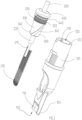
- the needle assembly may be a needle module 10 as illustrated in FIGS. 1 to 8B .
- the needle module 10 may be configured to apply tattoo or permanent make-up to skin.
- the needle module 10 may be a disposable module.
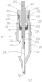
- needle module 10 includes housing 40 and a reciprocatively movable needle bundle 200 with a needle tip portion 210 mounted in the housing 40 for applying ink to the skin of a subject.
- the needle module 10 can be attached or connected to a tattoo machine (not shown), such as through a handle (not shown) of the tattoo machine.
- a base device (not shown) of the tattoo device includes a needle actuator (not shown) with a drive shaft (not shown) for actuating downward movement of the needle bundle 200 through a needle shaft portion 220 of the needle module 10.
- a suitable tattoo machine including its handle and base device
- these devices, parts, and their operation, and their coupling and interaction with housing 40 and needle shaft portion 220 are not described in detail herein.
- the needle bundle 200 is movably mounted in needle housing 40.
- the needle housing 40 includes a tubular body portion 100 and a removable cap 400.
- the body portion 100 has a tubular longitudinal inner channel 120 for receiving and housing the needle bundle 200.
- the channel 120 extends from an upper open end 122 to a lower open end 124 of the body portion 100, and has a central longitudinal axis (A), as shown in FIG. 4 (also see FIG. 5A ).
- the body portion 100 has an opening 150 at the lower open end 124 to allow the needle tip portion 210 of the needle bundle 200 to pass through.
- a needle guiding wall 110 is provided at the lower open end 124 adjacent the opening 150, which provides a guide surface for guiding movement of the needle tip portion 210.
- the opening 150 may be provided as an integral part of the body portion 100 as depicted in the drawings. However, in other embodiments, the opening 150 may be provided in a separate mouthpiece (not shown) attached to the body portion 100.
- the mouthpiece can be constructed and provided according to known techniques, including those disclosed in the references incorporated herein.
- the body portion 100 may also have one or more internal coupling ribs 130 at the upper open end 122 for coupling with and engaging the cap 400, as will be further described below.
- the removable cap 400 is provided at and coupled to the upper open end 122 of the tubular body portion 100.
- the cap 400 has a central opening 450 for allowing the needle shaft portion 220 to pass therethrough and axially move up and down during operation.
- Cap 400 also has a downward extending tube 410, with an external annular rim 420 and a lower external annular groove 430, which are provided and configured for engaging an upper end portion 320 of the tubular member 300 to affix the upper end portion 320 to the housing 40, as will be further described below.
- the cap 400 also has an upper annular groove 440 for engaging coupling ribs 130 of the body portion 100, so as to secure the cap 400 in position.
- body portion 100 and cap 400 may be made of a plastic material, or any other suitable material.
- the needle bundle 200 has a needle tip portion 210 attached to a needle shaft portion 220.
- the needle tip portion 210 of the needle bundle 200 may include one or more needle tips, which may be welded together, or otherwise bounded together.
- the needle tips may be formed of stainless steel or any other suitable material.
- the individual needle tip may have any suitable or known needle tip shape.
- the needle tips may be arranged, such as being tied together in an array, to form a tip portion that has a generally or substantially cylindrical or conical profile.
- an array of the needle tips may be arranged side-by-side to form a tip portion that has a generally flattened or band-shaped profile. Rows of side-by-side needles may also be stacked.
- Needle tip portion 210 may include 1-18 individual needle tips for “Round Liner” needles and “Round Shader” needles, or may include 4-27 needle tips for “Flat” needles and “Magnum” needles.
- the cross-sectional sizes or diameters of the needles or needle bundles will affect how the ink will flow.
- the smaller the needle tip size or narrower the diameter of the needle tip the finer and more controlled the stream of ink that flows off each needle tip.
- the needle tips in the same needle bundle may be of the same or similar sizes.
- the size of the needle tips may be selected based on the desired effects by the operator or user. Different sizes may be used for different reasons. Standard sizes of needles may be used.
- the diameters of the individual needles may be 0.25 mm, 0.30 mm, or 0.35 mm in some embodiments.
- the designs of the needle tips may be selected and vary as known in the art based on the desired tattooing techniques and purposes to be applied.
- the number of needles in a needle bundle 200 may vary from 1 to 27 or more as desired.
- commercially available round needle bundles typically have 1, 3, 5, 7, 8, 9, 11, 14, or 18 needles in each bundle.
- the overall profile of the needle bundle may change and vary depending on the number of needles in the bundle, their arrangement, the amount of soldering material used, or other factors.
- the needle tips in needle tip portion 210 are supported on needle shaft portion 220.
- the axis of needle shaft portion 220 may be axially aligned with the axis of channel 120 (axis A shown in FIG. 4 and FIG. 5A ), but is off-set from the axis of the needle tip portion 210 (see FIGS. 3 , 4 and 5A ).
- the needle shaft portion 220 may be formed of a rigid plastic material or another suitable material. The material in needle shaft portion 220 should have relatively high strength and high hardness and be wear-resistant so that its sufficiently rigid and strong to support stable movement of the needle tip portion 210 during operation.
- connection rod 215 may be made of steel such as stainless steel.
- An end of the connection rod 215 may be attached by an adhesive to needle shaft portion 220 in a bore 222 in the needle shaft portion 220.
- the needle tip portion 210 may be attached to the other end of the connection rod 215 such as by soldering.
- the connection rod 215 may have a diameter of about 1.5 mm, and the bore 222 in the needle shaft portion 220 may have a corresponding diameter.
- the needle tip portion 210 may have a cylindrical end which is directly inserted into the bore 222 of the needle shaft portion 220 for attachment to the needle shaft portion 220 such as by an adhesive.
- the needle tip portion 210 may have different sizes or different number of needles, and it is not necessary for the needle tip portion 210 to have a cylindrical end with the shape and size that match the shape and size of the bore 222.
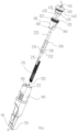
- Needle bundle 200 may reciprocally move longitudinally along axis A between the retracted position, illustrated in FIG. 5A , and the extended position, illustrated in FIG. 5B . As noted, the downward movement of needle bundle 200 is actuated by the actuator of the tattoo machine to which the needle bundle 200 is connected.
- an elastic tubular member 300 is provided within housing 40 and configured to pull the needle bundle 200 upward during each stroke cycle after the needle bundle 200 has been pushed down by an actuating or driving mechanism such as the drive shaft of the tattoo device described above.
- the tubular member 300 is also configured to bias the needle tip portion 210 of the needle bundle 200 laterally towards a lateral side of the channel 120, such as the needle guiding wall 110.
- the tubular member 300 has a central or longitudinal axis extending along the longitudinal direction, a sagittal plane, a frontal plane, and a transverse plane.
- the axial or longitudinal direction is up and down
- the sagittal plane is the plane in which the cross-sectional view of FIG. 1 is taken;
- the frontal plane is perpendicular to sagittal plane and along the axis with the direction facing the left hand side being the front direction (and the opposite direction being the rear direction);
- the transverse plane is perpendicular to both the sagittal plane and the frontal plane.
- the central axis is also shown along axis A in FIGS. 4 and 5A .
- the sagittal plane is along the line B-B shown in FIG. 7B .
- the frontal plane is along the line 7D-7D shown in FIGS. 7A and 7B .
- tubular member 300 is configured and assembled to provide a fluid seal between the lower open end 124 and the opening 450 of the cap 400 in the housing 40.
- the tubular member 300 may thus form a fluid seal between the lower open end 124 and the opening 450.
- a fluid such as ink or blood or other bodily fluid
- the seal provided by tubular member 300 will prevent the fluid from passing through opening 450 and from contaminating the upper components in the housing 40 including the upper section of the needle shaft portion 220 that will extend to outside the opening 450 during operation. Consequently, the fluid is contained within housing 40 and contamination of components of the tattoo device connected to the needle module 10 can be prevented.
- the fluid in the housing 40 may be disposed with the needle module 10 when the needle module 10 is discarded after use. For a new subject to be tattooed, a new needle module 10 may be used and connected to the tattoo device to prevent cross-contamination through the needle module.
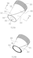
- the tubular member 300 includes a lower end portion 310, an upper end portion 320, and a middle, tubular section 330 connecting the upper end portion 320 and lower end portion 310.
- the upper end portion 320 of tubular member 300 is sized and shaped to close fit with the inner wall of tubular body portion 100.
- the upper end portion 320 has annular ridges extending along the circumference of the outer wall of upper end portion 320, which provide fluid sealing and frictional fitting with the inner wall of tubular body portion 100.
- cap 400 is configured to engage the upper end portion 320 of tubular member 300.
- the upper end portion 320 is securely retained between cap 400 and tubular body portion 100 in annular groove 430 by annular rim 420, and is thus sealingly affixed to housing 40.
- the lower end portion 310 of tubular member 300 is configured to sealingly engage the needle shaft portion 220 of needle bundle 200. As depicted in FIG. 8A , the lower end portion 310 of tubular member 300 may include a central opening 312 for allowing the needle shaft portion 220 to pass through and frictionally engaging the needle shaft portion 220 with fluid sealing.
- the middle tubular section 330 has a tubular shape and includes a helical ridge 340, or wall sections of different thickness separated by a helical boundary, as will be further described below.
- tubular member 300 in embodiments described herein and shown in the drawings is constructed differently from the biasing member disclosed in US 11,052,232 or the biasing member disclosed in US 20190217072 .
- the tubular member 300 in the illustrated embodiment includes two helical ridges 340 extending on its external surface.
- the two helical ridges 340 are symmetrically positioned with respective to the sagittal plane, which passes through the central longitudinal axis of the tubular member 300, which is aligned with axis A as shown in FIGS. 4 and 5A .
- the symmetry plane is the sagittal plane indicated by line B-B, and will be referred to as symmetry plane B hereinafter.
- the helical ridges 340 provide biasing forces that bias the needle bundle 200 laterally toward a lateral side of the channel 120 in addition to biasing the needle bundle 200 longitudinally upwards.
- a "helical ridge” refers to a ridge that extends along a cylindrical or conical external surface in both the axial or longitudinal direction and the circumferential direction.
- the three-dimensional (3D) profile of the ridge may form a generally geometrical helix or spiral.
- a helical ridge may have other curved or straight-edged shapes that do not form a perfect helix or spiral.
- a helical ridge may have a shape similar to that of the slanted tooth trace on a helical gear.
- a “helical boundary” may also refer to a boundary line that extends along a cylindrical or conical external surface in both the axial or longitudinal direction and the circumferential direction.
- a “helical” line refers to a line that extends in three dimensions and is not parallel to any straight line nor within any single plane.
- the helical ridge or boundary may be replaced with a different but still slanted ridge or boundary, where the ridge or boundary structure extends in both the longitudinal direction and a lateral perimetral direction along an external, perimetral surface of the tubular member 300.
- the slanted boundary or ridge may be curved when the lateral external perimeter of the tubular member has a curved section, such as when the perimeter is generally elliptical or has a curved section.
- the slanted boundary or ridge may also be straight if the lateral external perimeter of the tubular member is generally polygonal or has a straight section.
- a "lateral external perimeter" of the tubular member 300 refers to an external cross-sectional perimeter of the tubular member 300 in a transverse plane that is perpendicular to the axial or longitudinal direction of the tubular member 300.
- a line is considered “slanted” when the slanted line extends in both the longitudinal direction and the lateral perimetral direction.
- a slanted boundary or ridge therefore refers to an elongated boundary or ridge with a length that extends in both the longitudinal direction and the lateral perimetral direction, but does not include a single straight boundary or ridge elongated within an axial plane, or aligned symmetrically with respect to any axial plane.
- An axial plane is any plane that passes through the axis of the tubular member 300, and may be, for instance, the sagittal plane of a cylinder, frustum, or prism.
- a straight line on the external surface of a conical tubular body that extends within the sagittal plane of the tubular body and does not deviate from the sagittal plane is not considered a "slanted” line within the meaning of "slanted” as used herein.
- a straight ridge that extends along the sagittal plane and is symmetrically aligned with the sagittal plane is also not a “slanted” ridge within the meaning in this disclosure.
- a transversal line that is within the transversal plane and extends along the lateral perimeter is likewise not considered a "slanted” line herein.
- a wall or groove extending along the transversal line does not have a "slanted” boundary.
- a tubular body may have a cylindrical, frustum, or prismal external profile, which may have a generally elliptical or polygonal lateral external perimeter.
- An elliptical perimeter may be circular or oval.
- a polygonal perimeter may be square or rectangular, or hexagonal.
- Tubular bodies may include cylindrical shaped bodies, and frustums of cones and pyramids, such as truncated cones or truncated pyramidal shapes.
- the outer surfaces of a polygonal tubular body may have flat surfaces.
- a slanted boundary or slanted ridge on the tubular body may extend on a flat surface of the tubular body and is slanted with respect to the axial plane that is perpendicular to the flat surface.
- the slanted boundary or ridge on the flat surface may extend in a straight line but is still slanted with respect to that axial plane.
- a slanted boundary or ridge may thus be curved, such as being helical, or may extend along a straight line or have one or more straight sections.
- a slanted ridge or boundary provides a biasing force that has both a longitudinal component and a perimetral or latitudinal component, as well as an optional radial component.
- Providing a pair of symmetrically arranged corresponding slanted boundaries or slanted ridges however has the effect that when the tubular member 300, particularly the middle tubular portion 330, is stretched, the total biasing force applied by the tubular member 300 on the needle bundle 200 includes a larger radial component that biases the tip portion 210 of the needle bundle 200 towards the desired side of the channel 120, such as the guiding wall 110.
- the elastic tubular member 300 may have a generally cylindrical profile, frustum profile, or prism profile; and may have a generally polygonal or elliptical cross-section.
- the elliptical cross-section may be circular.
- the first and second ends of the tubular member are sealingly attached to the housing and the needle bundle, to prevent fluid communication between the lower open end and the upper open end of the housing.
- the tubular member 300 also functions as a seal.
- the tubular member 300 may comprise a diaphragm for this purpose.
- the helical ridges 340 extend from the first end to the second end of the tubular member 300.
- one or more shorter helical ridges, or a plurality separate ridge sections arranged in a helical pattern, may be provided on tubular member 300 to provide the lateral biasing force.
- the helical ridges 340 comprise generally straight side edges when viewed in a side elevation view.
- the side edges of the helical ridges 340 may have different shapes or profiles, as will be described in more detail below.
- the tubular member 300 may also be considered to include thicker portions and thinner portions, and the thicker and thinner portions are separated by a helical boundary therebetween that extends helically between the first end and the second end of the tubular member 300.
- the helical ridges 340 are thicker portions and the regions between the helical ridges 340 are the thinner portions, and the boundaries are at the bottom edges of the helical ridges 340.
- a tubular member 300 may comprise only two portions, one thicker portion and one thinner portion as illustrated in FIG. 9E .
- the two portions are separated by two helical boundaries 345, which may be arranged symmetrically with respect to a plane passing through a longitudinal axis of the tubular member 300.
- a curved side wall may be formed at the helical boundary between the thinner and thicker portions.
- the thinner portion of the tubular member 300 may comprise one or more bellows sections.
- the tubular member 300 may be provided with one bellows section on one side of the tubular member 300, such as at the wall 332 as illustrated in FIG. 9H , or with two bellows sections on opposite sides, such as at both the wall 332 and the opposite wall 334 as illustrated in FIG. 9I .
- Tubular member 300 may be formed of a silicone material or another resilient material such as latex, rubber, or an elastomer.
- the resilient material may be selected such that it is sufficiently elastic to be extended under stress to the desired extended position to expose the needle tips, but also sufficiently resilient to provide the required biasing force for returning the needle bundle 200 from the extended position back to the retracted position.
- tubular member 300 may be formed from a silicone material with a Shore hardness from about 30 A to about 50 A.
- the needle module 10 is attached to a handle of a tattoo device and the needle bundle 200 is driven by a needle actuator of the tattoo device to move downward so that the needle bundle 200 will move to the extended position in which the needle tips extend to outside of the lower opening 150 of the housing 40.
- the tubular member 300 conveniently facilitates reciprocal movement of the needle bundle 200 by pulling the needle bundle 200 upwards during each movement cycle after the needle bundle 200 has been pushed downward by the actuator.
- the biasing force is increased as the elastic tubular member 300 is stretched further and further during the downward movement of the needle bundle 200.
- the tubular member 300 also biases the needle tip portion 210 of the needle bundle 200 towards one side of the housing channel 120, such as towards the guiding wall 110 at the lower end near the opening 150. This lateral biasing of the needle tip portion 210 towards or against the guiding wall 110 can stabilize the needle bundle and maintain steady contact between the needle bundle 200 and the guiding wall 110.
- tubular member 300 conveniently provides a fluid seal between the lower open end 150 and the upper open end 450 of the housing 40.
- the upper end portion 320 of tubular member 300 is configured to engage the inner wall of body portion 100 and cap 400.
- the upper end portion 320 of the tubular member 300 may include a number of annual ridges 322, which are sized and shaped to close fit with the inner wall of the tubular body portion 100.
- the upper end portion 320 has 4 annular ridges extending along the circumference of the outer wall of the upper end portion 320.
- the inner wall of upper end portion 320 defines an opening that allows the needle shaft portion 220 of the needle bundle 200 to pass through and for engaging the cap 400.
- the upper end portion 320 is securely retained between cap 400 and tubular body portion 100 and is sealingly affixed to housing 40. As the upper end portion 320 of tubular member 300 is not attached to needle bundle 200, it does not move when the needle bundle 200 moves up and down. Thus, during operation the upper end portion 320 of tubular member 300 is fixed in position relative to the housing 40.
- the lower end portion 310 of tubular member 300 is configured to sealingly engage the needle shaft portion 220 of needle bundle 200.
- the lower end portion 310 has an opening 312, which is sized and shaped such that the needle shaft portion 220 forms a close fit with the lower end portion 310 at the opening 312, so as to form a fluid-tight seal between the tubular member 300 and the needle bundle 200, while at the same time allowing the shaft portion 220 to axially move up and down during operation without breaking the seal.
- the lower end portion 310 has a thickened section with an upward facing surface
- the needle shaft portion 220 may have an enlarged section, shoulder 230, that engages the upward facing surface of the lower end portion 310 of the tubular member 300.
- the thickened section of the lower end portion 310 is sized and shaped to closely couple with the shoulder 230, such that shoulder 230 exerts a downward force on the thickened section of the lower end portion 310 to pull the lower end portion 310 down when the needle bundle 200 is driven by the needle actuator to move towards the extended position.
- the tubular member 300 is stretched and the length of the tubular member 300 increases.
- the tubular member 300 produces a biasing force to bias the needle bundle 200 upward.
- the biasing force applied by the tubular member 300 pulls the needle bundle 200 back up to the retracted position.
- the needle bundle 200 may optionally include a collar 232 spaced from the shoulder 230 by a neck section 234 therebetween, so that the lower end portion 310 of the tubular member 300 can be received in the groove formed by the shoulder 230, collar 232 and neck section 234 to attach the lower end portion 310 to the needle bundle 200.
- the movement of the lower end portion 310 relative to the needle bundle 200 is limited and restricted by shoulder 230 and collar 232.
- the tubular member 300 may be formed of an elastic and resilient material, which may be selected such that it is sufficiently elastic to be extended under stress to the desired extended position to expose the needle tips, but also sufficiently resilient to provide the required biasing force for returning the needle bundle 200 from the extended position back to the retracted position, and for applying an adequate lateral biasing force to press the needle tip portion 210 of the needle bundle to a selected side of the channel in the housing 40, such as the guiding wall 110 as illustrated in FIG. 3 .
- the resilient material may be a silicone material with a Shore hardness from about 25 A to about 50 A.
- the upper end portion 320 and lower end portion 310 each has a wall thickness that is greater than the wall thickness of the middle tubular section 330.
- the upper end portion 320 and lower end portion 310 may be more rigid, less elastic, and less resilient, than the middle tubular section 330.
- FIGS. 5A and 5B show the needle module 10 with the needle bundle 200 in the retracted ( FIG. 5A ) and extended ( FIG. 5B ) positions respectively.
- tubular member 300 may still be slightly stretched and exert a biasing force to press the needle shaft portion 220 so that the needle tip portion 210 of the needle bundle 200 is pushed towards or against a side wall of the housing 40.
- the middle tubular section 330 of the tubular member 300 is further stretched and tensioned at the extended position by a length X, and thus produces a relatively large biasing force.
- the helical ridge 340 when stretched produces a biasing force F , generally directed along the helical direction of the helical ridge 340, as illustrated in FIG. 5B .
- the longitudinal component F 1 pulls the needle bundle 200 upward towards the retracted position, and the lateral component F 2 presses the tip end of the needle bundle 200 towards the guiding wall 110.
- the distance X between the retracted and extended positions of needle bundle 200 may be about 2 mm to about 5 mm, as the driving shaft of the needle actuator in a typical tattoo machine can move the same distance during each stroke.
- the tubular member 300 may still be tensioned.
- the tubular member 300 may be tension free and in a relaxed state.
- the needle shaft portion 220 may be initially pushed downward such as by about 2 mm to about 4 mm relative to the housing body portion 100. This downward movement of the needle shaft portion 220 tensions the tubular member 300 even though the needle bundle 200 is still in the retracted position initially.
- the needle shaft portion 220 and needle bundle 200 may be pushed to move further downward by about 2 mm to about 5 mm.
- the annular rim 420 and groove 430 of cap 400 engages the upper end portion 320 of tubular member 300, and upper end portion 320 is secured in position between the cap 400 and the inner wall at the upper end of channel 120, so that upper end portion 320 cannot move relative to the housing body portion 100 in the longitudinal direction (along axis A) during operation while the needle bundle 200 reciprocally moves up and down relative to the body portion 100.
- the upper end portion 320 of tubular member 300 is also configured to abut and resiliently grip the inner wall of the housing body portion 100 and to provide a tight seal between the upper end portion 320 and the housing body portion 100.
- each ridge may be rib-shaped.
- the lower opening 150 in housing 40 may have different shapes and sizes.
- the opening 150 may have a corresponding rectangular profile.
- the needle guiding wall 110 may have a corresponding flat inner surface, also as illustrated in FIGS. 3 and 4 .
- the symmetry plane B passes through and is parallel to the central axis A and is perpendicular to the guiding wall 110 of the housing body portion 100.
- Two helical ridges 340 are arranged symmetrically with respect to the symmetry plane B.
- the needle tip portion 210 of the needle bundle 200 may have a generally cylindrical overall profile, in which case the opening 150 of the housing 40 may be circular.
- the inner wall of the guiding wall 110 may also be curved.
- the needle bundle 200 may contact the guiding wall 110 along a longitudinal line, which is referred to the needle guiding line herein.
- the symmetrical plane B may contain both the axis A and the needle guiding line.
- the helical ridges 340 on tubular member 300 may have different shapes and configurations.
- a helical ridge 340 may have curved side edges when viewed in the side elevation view.
- the edges of the helical ridge 340 in some embodiments may be curved in the face-on elevation view, when the viewer is directly facing the helical ridge 340.
- a helical ridge 340 may have generally parallel side edges as shown in FIGS. 7A or may have unparallel side edges as shown in FIG. 9A .
- a helical ridge 340 may have helically aligned step-shaped side edges. That is, the edges of the helical ridge 340 in some embodiments may be step-shaped or zig-zap shaped in the face-on elevation view. In alternative embodiments, such as when the tubular member 340 has a flat side surface, the step-shaped side edges may also be aligned along a straight or curved line that extends on the flat surface in both the longitudinal direction and the lateral perimetral direction.
- Two or more helical ridges 340 may also be arranged side-by-side, and generally parallel to one another, as illustrated in FIG. 9C .
- the two or more helical ridges 340 may be positioned on one side of the tubular member 300.
- the helical ridges 340 may have different widths in different embodiments.
- the helical ridges 340 may also have different heights in different embodiments. As can be appreciated, a wider or taller ridge may provide a larger biasing force.
- FIGS. 9D, 9E and 9F illustrate that a helical ridge 340 may have different widths in different embodiments, and a helical ridge 340 may be positioned at different positions.
- the helical ridge 340 has a relatively large width and the thinner wall area 332 is much larger in area size than the thinner wall area 334.
- the middle tubular section 330 of tubular member 300 has only different regions, the thinner wall area 332 and the thicker helical ridge 340 (the area 334 does not exist or has a size of zero), which are separated by the helical boundary 345.
- the thinner wall area 332 has a larger area size as compared to FIG. 9E
- the helical ridge 340 has a correspondingly smaller area size as compared to FIG. 9E .
- FIGS. 10A and 10B show perspective views of tubular member 300 shown in FIG. 9E and 9F respectively.
- the wall 332 and wall 334 have different wall thicknesses.
- wall 332 may be thinner than wall 334.
- walls 332 and 334 produce different biasing forces, the force produced by wall 334 being larger than that produced by wall 332.
- Such force differential affects the total lateral biasing force, in addition to the effects produced by the helical ridge 340.
- FIG. 9H illustrates an embodiment of the tubular member 300 where the tubular wall 332 in the middle section is corrugated or is a bellows section. Wall 334 in FIG. 9H is not corrugated.
- FIG. 9I illustrates an embodiment of the tubular member 300 where both the wall 332 and wall 334 are corrugated or bellows sections.
- the walls at different areas may have different rectified lengths, which are longer than a straight wall.
- its rectified length refers to the length of the curve that has been rectified.
- the curve gives a straight line segment with the same length as the curve's arc length.
- its rectified length is the same as the length of the straight line.
- wall 334 has a shorter rectified length than wall 332 so that wall 334 would be tensioned more than wall 332 when the middle tubular section 330 is stretched due to downward movement of the needle bundle 200.
- the corrugated wall 332 is less tensioned than the non-corrugated wall 334 when the tubular member 300 is stretched.
- the longitudinal forces produced by walls 332 and 334 are not balanced and the imbalance produces an additional lateral biasing force.
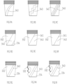
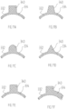
- a helical ridge 340 may have any number of cross-sectional shapes or profiles, some of which are illustrated in FIGS. 11A to 11F .
- the cross-section profile of a helical ridge 340 may be generally polygonal or semicircular.
- the polygonal cross-section may be square, as illustrated in FIG. 11A ; trapezoidal, as illustrated in FIG. 11B ; triangular, as illustrated in FIG. 11D ; or rectangular, as illustrated in FIGS. 11E and 11F .
- the cross-section profile of a helical ridge 340 may also include a semicircular edge as illustrated in FIG. 11C .
- wall 332 and wall 334 have the same wall thickness.
- wall 334 is thicker than wall 332.
- the wall thickness at helical ridge 340 is larger than at both walls 332 and 334.
- the helical ridge 340 has a generally rectangular cross-sectional profile, but the top edge may be curved or arched.
- the outer top edge of helical ridge 340 may be concentric with the tubular section formed by walls 332 and 334.
- the helical ridge 340 or different portions having a helical boundary and different thickness when stretched, can provide a biasing force that biases the needle bundle both longitudinally towards the retracted position and laterally towards a lateral side of the channel 120.
- Tubular member 300 also conveniently provides a fluid seal between the upper open end and lower open end of the housing channel 120.
- a tubular member as described herein provides a number of beneficial effects or advantages.
- a tubular member with one or more helical ridges as described herein is easier to manufacture, as compared to an elastic tubing with opposite sides of different rectified lengths and corrugated tubular sections.
- the internal shapes of the molds for producing the tubular member 300 illustrated in FIGS. 7A, 7C, and 7D are not as complex as in a mold for producing a biasing member with different rectified lengths and corrugated tubular sections.
- the production efficiency and product yield can be improved.
- the elastic membrane disclosed in CN 106902452A have regions of different thicknesses and the boundaries between the different regions extend in the axial or longitudinal direction.
- the elastic membrane of CN 106902452A may have an elastic rib extending along the direction of the needle movement on one side of the elastic membrane.
- a drawback of the elastic membrane disclosed in CN 106902452A is that it is difficult to adjust amounts, or ratio, of the generated forces in different directions. For example, while the thicknesses of the different portions of the membrane may be adjusted to generate different force ratios, a large thickness difference in the same membrane can result in manufacturing complexity and reduction in performance and product durability.
- a helical ridge or boundary as described herein can provide additional lateral forces that can be more easily adjusted by changing the helical direction without changing the thickness of the helical ridge or any portion of the tubular membrane.
- a higher lateral to longitudinal biasing force ratio may be achieved with a helical ridge or boundary without changing the thicknesses of the tubular member.
- the needle module 10 may be a single-use disposable module, and can be used directly after opening the needle module packaging without further cleaning, sanitization, or sterilization, and can be disposed after a single use without cleaning or any other treatment.
- single use may refer to use of a needle or needle module for one complete operation on a single individual subject.
- different needle modules may be used to apply different ink colors or for different purposes. For example, it may be typical to use two to five different types of needles during a single operation on a subject, depending on the complexity of the design to be applied.
- the tubular member 300 is configured to provide both a longitudinal biasing force and a lateral or radial biasing force, with the provision of a helical ridge or helical boundary.
- a tubular member with a pair of corresponding helical or slanted ridges arranged symmetrically with respect to the sagittal plane provides certain benefits over a single ridge extending along the sagittal plane.
- the pair of symmetrical ridges can be made thicker or larger and provide a stronger radial biasing force without interfering with the guiding wall 110. This is particularly helpful when the space in the channel 120 is limited so the tubular member 300 needs to be small in size with relatively thin walls.
- the tubular member 300 also separates the lower open end of body portion 100 from the upper open end of body portion 100, and provides a fluid-tight seal in the channel 120 between the lower end and the upper end of the housing 40 such that bodily fluids exiting from the punctured skin of the subject being treated will be prevented from travelling from the needle tip portion 210 to the upper end of the housing through the inner channel 120.
- the seal also prevents ink from entering and passing through the upper end of needle housing 40.
- the seal thus conveniently prevents the subject's bodily fluids and ink from contacting parts of the needle handle (not shown) or tattoo machine (not shown) connected to the needle module 10.
- the tattoo machine and the needle handle may be reused after each treatment or after changing the needle module, without the need to re-sterilize any part of the tattoo machine.
- the needle handle may also be disposable.
- tubular member 300 may have a polygonal cross-section and may include slanted ridges or boundaries on its external surface, which replace the helical boundaries or ridges, but still provide similar biasing effects as discussed herein.
- a needle module or needle assembly described herein may be used or adapted to apply other types of liquids to skin.
- the applied liquid may include colored liquids or pigments, or may include a medicinal or therapeutic agent, collagen, or other like or similar substances.
- the needle assembly may be used in a liquid applicator for applying the selected liquid.
- Reference Corresponding element 10 Needle module 40 Housing 100 Body portion 110 Guiding wall 120 Channel 122 Upper open end 124 Lower open end 130 Coupling rib 150 (lower end) Opening 200 Needle Bundle 210 Needle Tip portion 215 Connection rod 220 Needle shaft portion 222 Bore 230 Shoulder 232 Collar 234 Neck section 300 Tubular member 310 Lower end portion 312 Central opening 320 Upper end portion 322 Annular ridges 330 Middle tubular section 332 First wall 334 Second wall 340 Helical ridge 345 Boundary 400 Cap 410 Tube 420 Annular rim 430 (lower) Groove 440 (upper) Groove 450 (central) Opening A-A Central (longitudinal) axis B-B Symmetry (sagittal) plane 7D-7D Frontal plane
Landscapes
- Health & Medical Sciences (AREA)
- Engineering & Computer Science (AREA)
- Hematology (AREA)
- Life Sciences & Earth Sciences (AREA)
- Medical Informatics (AREA)
- Anesthesiology (AREA)
- Biomedical Technology (AREA)
- Heart & Thoracic Surgery (AREA)
- Virology (AREA)
- Dermatology (AREA)
- Animal Behavior & Ethology (AREA)
- General Health & Medical Sciences (AREA)
- Public Health (AREA)
- Veterinary Medicine (AREA)
- Infusion, Injection, And Reservoir Apparatuses (AREA)
- Coating Apparatus (AREA)
Priority Applications (2)
| Application Number | Priority Date | Filing Date | Title |
|---|---|---|---|
| CA3191274A CA3191274A1 (en) | 2022-02-28 | 2023-02-27 | Needle assembly for liquid applicator |
| US18/455,478 US12409306B2 (en) | 2022-02-28 | 2023-08-24 | Needle assembly for liquid applicator |
Applications Claiming Priority (1)
| Application Number | Priority Date | Filing Date | Title |
|---|---|---|---|
| US17/682,831 US12246156B2 (en) | 2022-02-28 | 2022-02-28 | Needle assembly for liquid applicator |
Publications (2)
| Publication Number | Publication Date |
|---|---|
| EP4233979A2 true EP4233979A2 (de) | 2023-08-30 |
| EP4233979A3 EP4233979A3 (de) | 2023-09-13 |
Family
ID=85383002
Family Applications (1)
| Application Number | Title | Priority Date | Filing Date |
|---|---|---|---|
| EP23158470.7A Pending EP4233979A3 (de) | 2022-02-28 | 2023-02-24 | Nadelanordnung für flüssigkeitsapplikator |
Country Status (4)
| Country | Link |
|---|---|
| US (1) | US12246156B2 (de) |
| EP (1) | EP4233979A3 (de) |
| CN (1) | CN116115897B (de) |
| CA (1) | CA3191274A1 (de) |
Families Citing this family (1)
| Publication number | Priority date | Publication date | Assignee | Title |
|---|---|---|---|---|
| CN115120858B (zh) | 2022-05-12 | 2024-03-29 | 肖龙 | 用于纹身装置的针组件 |
Citations (4)
| Publication number | Priority date | Publication date | Assignee | Title |
|---|---|---|---|---|
| CN106902452A (zh) | 2017-01-12 | 2017-06-30 | 苏州市相城区棱峰医疗用品有限公司 | 一种纹身装置 |
| US20190217072A1 (en) | 2018-01-18 | 2019-07-18 | Long Xiao | Devices for applying liquid to skin |
| US10806915B2 (en) | 2017-08-30 | 2020-10-20 | Long Xiao | Devices for applying coloured liquid to skin |
| US11052232B2 (en) | 2018-07-17 | 2021-07-06 | Long Xiao | Devices for applying liquid to skin |
Family Cites Families (9)
| Publication number | Priority date | Publication date | Assignee | Title |
|---|---|---|---|---|
| US6475194B2 (en) * | 2000-04-05 | 2002-11-05 | Gem Plastics, Inc. | Safety syringe |
| PL1618915T3 (pl) * | 2004-07-21 | 2007-06-29 | Mt Derm Gmbh | Przyrząd do miejscowego nakłuwania skóry |
| US20080287978A1 (en) * | 2007-05-19 | 2008-11-20 | Hickman Iii Charles B | Medical mapping device |
| US8317812B2 (en) * | 2009-07-29 | 2012-11-27 | Wah Leong Lum | Lancet device with lance retraction |
| TW201127434A (en) * | 2009-09-30 | 2011-08-16 | Sanofi Aventis Deutschland | Drug delivery device |
| KR102379264B1 (ko) * | 2013-12-04 | 2022-03-29 | 메드메틱스, 엘엘씨 | 피부 천자 디바이스 |
| KR101587235B1 (ko) * | 2015-04-23 | 2016-01-20 | 제이에스케이바이오메드 (주) | 전동식 약물 주입장치 |
| US11400268B2 (en) * | 2018-10-11 | 2022-08-02 | Fk Irons Inc. | Electromagnetically driven tattoo machine and system |
| CN211410687U (zh) | 2019-12-12 | 2020-09-04 | 肖启松 | 一种纹身针装置 |
-
2022
- 2022-02-28 US US17/682,831 patent/US12246156B2/en active Active
-
2023
- 2023-02-10 CN CN202310143462.8A patent/CN116115897B/zh active Active
- 2023-02-24 EP EP23158470.7A patent/EP4233979A3/de active Pending
- 2023-02-27 CA CA3191274A patent/CA3191274A1/en active Pending
Patent Citations (4)
| Publication number | Priority date | Publication date | Assignee | Title |
|---|---|---|---|---|
| CN106902452A (zh) | 2017-01-12 | 2017-06-30 | 苏州市相城区棱峰医疗用品有限公司 | 一种纹身装置 |
| US10806915B2 (en) | 2017-08-30 | 2020-10-20 | Long Xiao | Devices for applying coloured liquid to skin |
| US20190217072A1 (en) | 2018-01-18 | 2019-07-18 | Long Xiao | Devices for applying liquid to skin |
| US11052232B2 (en) | 2018-07-17 | 2021-07-06 | Long Xiao | Devices for applying liquid to skin |
Also Published As
| Publication number | Publication date |
|---|---|
| EP4233979A3 (de) | 2023-09-13 |
| CN116115897A (zh) | 2023-05-16 |
| US12246156B2 (en) | 2025-03-11 |
| US20230270986A1 (en) | 2023-08-31 |
| CA3191274A1 (en) | 2023-08-28 |
| CN116115897B (zh) | 2025-04-01 |
Similar Documents
| Publication | Publication Date | Title |
|---|---|---|
| CN110404159B (zh) | 针组件和液体施加装置 | |
| CN109876288B (zh) | 用于液体施加装置的针组合装置及液体施加装置 | |
| US11172954B2 (en) | Reciprocating rotary surgical cutting device and system for tissue resecting, and method for its use | |
| EP4233979A2 (de) | Nadelanordnung für flüssigkeitsapplikator | |
| KR101692983B1 (ko) | 니들유닛 및 이를 구비한 문신장치 | |
| US8118036B2 (en) | Hair dyeing comb with interchangeable comb heads | |
| US7922737B1 (en) | Reciprocating rotary arthroscopic surgical instrument | |
| EP3207885B1 (de) | Medizinisches instrument mit instrumentenspülsystem | |
| KR102379264B1 (ko) | 피부 천자 디바이스 | |
| US8282575B2 (en) | Endoscopic puncture needle and method of acquiring tissue from a target region by using the endoscopic puncture needle | |
| JP2016525900A (ja) | 身体挿管装置用剛性ヘッド | |
| JPS5985936A (ja) | 液体移送装置 | |
| CA3130122A1 (en) | Devices, systems, and techniques for medical cleaning valves | |
| EP3415193B1 (de) | Nadelführungsvorrichtung für eine hautstecheinrichtung und hautstecheinrichtung | |
| EP2042205B1 (de) | Spritze mit Kappe und Kappenentfernungshilfsmittel | |
| CN109248374B (zh) | 用于施加彩色液体至皮肤的应用装置的手柄 | |
| US12409306B2 (en) | Needle assembly for liquid applicator | |
| EP3160296A1 (de) | Zahnbürste mit bewegten elementen | |
| EP3863560B1 (de) | Düsenköpfe für eine reinigungsvorrichtung mit flüssigblattreinigungswirkung | |
| GB2604938A (en) | Dental nozzle device | |
| EP3513832A1 (de) | Vorrichtungen zum auftragen von flüssigkeit auf die haut | |
| US11197986B2 (en) | Devices for applying coloured liquid to skin | |
| CN115120858B (zh) | 用于纹身装置的针组件 | |
| US12366296B2 (en) | Stopcock, plug for a stopcock, and method for producing a plug for a stopcock | |
| US20220378185A1 (en) | Manually operated water-pic |
Legal Events
| Date | Code | Title | Description |
|---|---|---|---|
| PUAI | Public reference made under article 153(3) epc to a published international application that has entered the european phase |
Free format text: ORIGINAL CODE: 0009012 |
|
| STAA | Information on the status of an ep patent application or granted ep patent |
Free format text: STATUS: THE APPLICATION HAS BEEN PUBLISHED |
|
| PUAL | Search report despatched |
Free format text: ORIGINAL CODE: 0009013 |
|
| AK | Designated contracting states |
Kind code of ref document: A2 Designated state(s): AL AT BE BG CH CY CZ DE DK EE ES FI FR GB GR HR HU IE IS IT LI LT LU LV MC ME MK MT NL NO PL PT RO RS SE SI SK SM TR |
|
| AK | Designated contracting states |
Kind code of ref document: A3 Designated state(s): AL AT BE BG CH CY CZ DE DK EE ES FI FR GB GR HR HU IE IS IT LI LT LU LV MC ME MK MT NL NO PL PT RO RS SE SI SK SM TR |
|
| RIC1 | Information provided on ipc code assigned before grant |
Ipc: A61M 37/00 20060101AFI20230807BHEP |
|
| STAA | Information on the status of an ep patent application or granted ep patent |
Free format text: STATUS: REQUEST FOR EXAMINATION WAS MADE |
|
| 17P | Request for examination filed |
Effective date: 20240311 |
|
| RBV | Designated contracting states (corrected) |
Designated state(s): AL AT BE BG CH CY CZ DE DK EE ES FI FR GB GR HR HU IE IS IT LI LT LU LV MC ME MK MT NL NO PL PT RO RS SE SI SK SM TR |