EP4233937A2 - Infusion devices and related patient ratio adjustment methods - Google Patents
Infusion devices and related patient ratio adjustment methods Download PDFInfo
- Publication number
- EP4233937A2 EP4233937A2 EP23177094.2A EP23177094A EP4233937A2 EP 4233937 A2 EP4233937 A2 EP 4233937A2 EP 23177094 A EP23177094 A EP 23177094A EP 4233937 A2 EP4233937 A2 EP 4233937A2
- Authority
- EP
- European Patent Office
- Prior art keywords
- value
- bolus
- amount
- residual
- glucose
- Prior art date
- Legal status (The legal status is an assumption and is not a legal conclusion. Google has not performed a legal analysis and makes no representation as to the accuracy of the status listed.)
- Pending
Links
Images


Classifications
-
- A—HUMAN NECESSITIES
- A61—MEDICAL OR VETERINARY SCIENCE; HYGIENE
- A61M—DEVICES FOR INTRODUCING MEDIA INTO, OR ONTO, THE BODY; DEVICES FOR TRANSDUCING BODY MEDIA OR FOR TAKING MEDIA FROM THE BODY; DEVICES FOR PRODUCING OR ENDING SLEEP OR STUPOR
- A61M5/00—Devices for bringing media into the body in a subcutaneous, intra-vascular or intramuscular way; Accessories therefor, e.g. filling or cleaning devices, arm-rests
- A61M5/14—Infusion devices, e.g. infusing by gravity; Blood infusion; Accessories therefor
- A61M5/168—Means for controlling media flow to the body or for metering media to the body, e.g. drip meters, counters ; Monitoring media flow to the body
- A61M5/172—Means for controlling media flow to the body or for metering media to the body, e.g. drip meters, counters ; Monitoring media flow to the body electrical or electronic
- A61M5/1723—Means for controlling media flow to the body or for metering media to the body, e.g. drip meters, counters ; Monitoring media flow to the body electrical or electronic using feedback of body parameters, e.g. blood-sugar, pressure
-
- A—HUMAN NECESSITIES
- A61—MEDICAL OR VETERINARY SCIENCE; HYGIENE
- A61M—DEVICES FOR INTRODUCING MEDIA INTO, OR ONTO, THE BODY; DEVICES FOR TRANSDUCING BODY MEDIA OR FOR TAKING MEDIA FROM THE BODY; DEVICES FOR PRODUCING OR ENDING SLEEP OR STUPOR
- A61M5/00—Devices for bringing media into the body in a subcutaneous, intra-vascular or intramuscular way; Accessories therefor, e.g. filling or cleaning devices, arm-rests
- A61M5/14—Infusion devices, e.g. infusing by gravity; Blood infusion; Accessories therefor
- A61M5/142—Pressure infusion, e.g. using pumps
- A61M5/145—Pressure infusion, e.g. using pumps using pressurised reservoirs, e.g. pressurised by means of pistons
- A61M5/1452—Pressure infusion, e.g. using pumps using pressurised reservoirs, e.g. pressurised by means of pistons pressurised by means of pistons
-
- A—HUMAN NECESSITIES
- A61—MEDICAL OR VETERINARY SCIENCE; HYGIENE
- A61M—DEVICES FOR INTRODUCING MEDIA INTO, OR ONTO, THE BODY; DEVICES FOR TRANSDUCING BODY MEDIA OR FOR TAKING MEDIA FROM THE BODY; DEVICES FOR PRODUCING OR ENDING SLEEP OR STUPOR
- A61M5/00—Devices for bringing media into the body in a subcutaneous, intra-vascular or intramuscular way; Accessories therefor, e.g. filling or cleaning devices, arm-rests
- A61M5/14—Infusion devices, e.g. infusing by gravity; Blood infusion; Accessories therefor
- A61M5/142—Pressure infusion, e.g. using pumps
- A61M2005/14208—Pressure infusion, e.g. using pumps with a programmable infusion control system, characterised by the infusion program
-
- A—HUMAN NECESSITIES
- A61—MEDICAL OR VETERINARY SCIENCE; HYGIENE
- A61M—DEVICES FOR INTRODUCING MEDIA INTO, OR ONTO, THE BODY; DEVICES FOR TRANSDUCING BODY MEDIA OR FOR TAKING MEDIA FROM THE BODY; DEVICES FOR PRODUCING OR ENDING SLEEP OR STUPOR
- A61M2205/00—General characteristics of the apparatus
- A61M2205/50—General characteristics of the apparatus with microprocessors or computers
- A61M2205/502—User interfaces, e.g. screens or keyboards
-
- A—HUMAN NECESSITIES
- A61—MEDICAL OR VETERINARY SCIENCE; HYGIENE
- A61M—DEVICES FOR INTRODUCING MEDIA INTO, OR ONTO, THE BODY; DEVICES FOR TRANSDUCING BODY MEDIA OR FOR TAKING MEDIA FROM THE BODY; DEVICES FOR PRODUCING OR ENDING SLEEP OR STUPOR
- A61M2205/00—General characteristics of the apparatus
- A61M2205/50—General characteristics of the apparatus with microprocessors or computers
- A61M2205/52—General characteristics of the apparatus with microprocessors or computers with memories providing a history of measured variating parameters of apparatus or patient
-
- A—HUMAN NECESSITIES
- A61—MEDICAL OR VETERINARY SCIENCE; HYGIENE
- A61M—DEVICES FOR INTRODUCING MEDIA INTO, OR ONTO, THE BODY; DEVICES FOR TRANSDUCING BODY MEDIA OR FOR TAKING MEDIA FROM THE BODY; DEVICES FOR PRODUCING OR ENDING SLEEP OR STUPOR
- A61M2205/00—General characteristics of the apparatus
- A61M2205/70—General characteristics of the apparatus with testing or calibration facilities
- A61M2205/702—General characteristics of the apparatus with testing or calibration facilities automatically during use
-
- A—HUMAN NECESSITIES
- A61—MEDICAL OR VETERINARY SCIENCE; HYGIENE
- A61M—DEVICES FOR INTRODUCING MEDIA INTO, OR ONTO, THE BODY; DEVICES FOR TRANSDUCING BODY MEDIA OR FOR TAKING MEDIA FROM THE BODY; DEVICES FOR PRODUCING OR ENDING SLEEP OR STUPOR
- A61M2230/00—Measuring parameters of the user
- A61M2230/005—Parameter used as control input for the apparatus
-
- A—HUMAN NECESSITIES
- A61—MEDICAL OR VETERINARY SCIENCE; HYGIENE
- A61M—DEVICES FOR INTRODUCING MEDIA INTO, OR ONTO, THE BODY; DEVICES FOR TRANSDUCING BODY MEDIA OR FOR TAKING MEDIA FROM THE BODY; DEVICES FOR PRODUCING OR ENDING SLEEP OR STUPOR
- A61M2230/00—Measuring parameters of the user
- A61M2230/20—Blood composition characteristics
- A61M2230/201—Glucose concentration
Definitions
- one or more of the infusion device 102, the sensing arrangement 104, the CCD 106, and/or the computer 108 includes a transmitter, a receiver, and/or other transceiver electronics that allow for communication with other components of the infusion system 100, so that the sensing arrangement 104 may transmit sensor data or monitor data to one or more of the infusion device 102, the CCD 106 and/or the computer 108.
- the sensing arrangement 104 may be secured to the body of the user or embedded in the body of the user at a location that is remote from the location at which the infusion device 102 is secured to the body of the user. In various other embodiments, the sensing arrangement 104 may be incorporated within the infusion device 102. In other embodiments, the sensing arrangement 104 may be separate and apart from the infusion device 102, and may be, for example, part of the CCD 106. In such embodiments, the sensing arrangement 104 may be configured to receive a biological sample, analyte, or the like, to measure a condition of the user.
- the CCD 106 and/or the computer 108 may include electronics and other components configured to perform processing, delivery routine storage, and to control the infusion device 102 in a manner that is influenced by sensor data measured by and/or received from the sensing arrangement 104.
- the infusion device 102 may be made with more simplified electronics.
- the infusion device 102 may include all control functions, and may operate without the CCD 106 and/or the computer 108.
- the CCD 106 may be a portable electronic device.
- the infusion device 102 and/or the sensing arrangement 104 may be configured to transmit data to the CCD 106 and/or the computer 108 for display or processing of the data by the CCD 106 and/or the computer 108.
- the sensing arrangement 104 and the CCD 106 may be used for determining glucose levels in the blood and/or body fluids of the user without the use of, or necessity of, a wire or cable connection between the infusion device 102 and the sensing arrangement 104 and/or the CCD 106.
- the infusion device 102 is configured to deliver fluid in response to the condition sensed by the sensing arrangement 104.
- the sensing arrangement 104 continues to sense or otherwise quantify a current condition of the user, thereby allowing the infusion device 102 to deliver fluid continuously in response to the condition currently (or most recently) sensed by the sensing arrangement 104 indefinitely.
- the sensing arrangement 104 and/or the infusion device 102 may be configured to utilize the closed-loop system only for a portion of the day, for example only when the user is asleep or awake.
- FIGS. 2-4 depict one exemplary embodiment of a fluid infusion device 200 (or alternatively, infusion pump) suitable for use in an infusion system, such as, for example, as infusion device 102 in the infusion system 100 of FIG. 1 .
- the fluid infusion device 200 is a portable medical device designed to be carried or worn by a patient (or user), and the fluid infusion device 200 may leverage any number of conventional features, components, elements, and characteristics of existing fluid infusion devices, such as, for example, some of the features, components, elements, and/or characteristics described in United States Patent numbers 6,485,465 and 7,621,893 . It should be appreciated that FIGS. 2-4 depict some aspects of the infusion device 200 in a simplified manner; in practice, the infusion device 200 could include additional elements, features, or components that are not shown or described in detail herein.
- the shoulder portion 215 of the slide 206 contacts or otherwise engages the plunger 217 to displace the plunger 217 in the axial direction 218.
- the slide 206 may include a threaded tip 213 capable of being detachably engaged with internal threads 404 on the plunger 217 of the reservoir 205, as described in detail in United States patent numbers 6,248,093 and 6,485,465 , which are incorporated by reference herein.
- the power supply may be a solar panel, capacitor, AC or DC power supplied through a power cord, or the like.
- the control electronics 224 may operate the motor of the motor assembly 207 and/or drive system 208 in a stepwise manner, typically on an intermittent basis; to administer discrete precise doses of the fluid to the user according to programmed delivery profiles.
- the control electronics 224 maintains and/or provides information to the display 226 regarding program parameters, delivery profiles, pump operation, alarms, warnings, statuses, or the like, which may be adjusted using the HMI elements 232, 234.
- the HMI elements 232, 234 may be realized as physical objects (e.g., buttons, knobs, joysticks, and the like) or virtual objects (e.g., using touch-sensing and/or proximity-sensing technologies).
- the display 226 may be realized as a touch screen or touch-sensitive display, and in such embodiments, the features and/or functionality of the HMI elements 232, 234 may be integrated into the display 226 and the HMI 230 may not be present.
- the electronics assembly 204 may also include alert generating elements coupled to the control electronics 224 and suitably configured to generate one or more types of feedback, such as, without limitation: audible feedback; visual feedback; haptic (physical) feedback; or the like.
- the sensor assembly 210 is positioned between the motor assembly 207 and secured by the capping member 212, which prevents displacement of the sensor assembly 210 in a downward direction opposite the direction of arrow 218, such that the sensor assembly 210 is subjected to a reactionary compressive force when the drive system 208 and/or motor assembly 207 is operated to displace the slide 206 in the axial direction 218 in opposition to the fluid pressure in the reservoir 205.
- the compressive force applied to the sensor assembly 210 is correlated with the fluid pressure in the reservoir 205.
- the blood glucose meter 530 outputs or otherwise provides a measured blood glucose value that may be utilized as a reference measurement for calibrating the sensing arrangement 504 and converting a measurement value indicative of the user's interstitial fluid glucose level into a corresponding calibrated blood glucose value.
- the calibrated blood glucose value calculated based on the electrical signals output by the sensing element(s) of the sensing arrangement 504 may alternatively be referred to herein as the sensor glucose value, the sensed glucose value, or variants thereof.
- the motor control module 512 is coupled to the motor driver module 514, and the motor control module 512 generates or otherwise provides command signals that operate the motor driver module 514 to provide current (or power) from the energy source 503 to the motor 507 to displace the plunger 517 in response to receiving, from a pump control system 520, a dosage command indicative of the desired amount of fluid to be delivered.
- the motor control module 512 is configured to receive or otherwise obtain a commanded dosage from the pump control system 520, convert the commanded dosage to a commanded translational displacement of the plunger 517, and command, signal, or otherwise operate the motor driver module 514 to cause the rotor of the motor 507 to rotate by an amount that produces the commanded translational displacement of the plunger 517.
- the motor control module 512 may determine an amount of rotation of the rotor required to produce translational displacement of the plunger 517 that achieves the commanded dosage received from the pump control system 520.
- FIG. 6 depicts an exemplary embodiment of a pump control system 600 suitable for use as the pump control system 520 in FIG. 5 in accordance with one or more embodiments.
- the illustrated pump control system 600 includes, without limitation, a pump control module 602, a communications interface 604, and a data storage element (or memory) 606.
- the pump control module 602 is coupled to the communications interface 604 and the memory 606, and the pump control module 602 is suitably configured to support the operations, tasks, and/or processes described herein.
- the pump control module 602 is also coupled to one or more user interface elements 608 (e.g., user interface 230, 540) for receiving user input and providing notifications, alerts, or other therapy information to the user.
- FIG. 6 depicts an exemplary embodiment of a pump control system 600 suitable for use as the pump control system 520 in FIG. 5 in accordance with one or more embodiments.
- the illustrated pump control system 600 includes, without limitation, a pump control module 602, a communications interface 604, and a data storage element (or
- the pump control module 602 generally represents the hardware, circuitry, logic, firmware and/or other component of the pump control system 600 that is coupled to the communications interface 604 and configured to determine dosage commands for operating the motor 506 to deliver fluid to the body 501 based on data received from the sensing arrangement 504 and perform various additional tasks, operations, functions and/or operations described herein.
- pump control module 602 implements or otherwise executes a command generation application 610 that supports one or more autonomous operating modes and calculates or otherwise determines dosage commands for operating the motor 506 of the infusion device 502 in an autonomous operating mode based at least in part on a current measurement value for a condition in the body 501 of the user.
- the command generation application 610 may determine a dosage command for operating the motor 506 to deliver insulin to the body 501 of the user based at least in part on the current glucose measurement value most recently received from the sensing arrangement 504 to regulate the user's blood glucose level to a target reference glucose value.
- the memory 606 stores a plurality of different patient-specific carbohydrate ratios, with each carbohydrate ratio being associated with a particular bolus context, such as, for example, a particular time of day (e.g., a 6 AM - 10 AM time window, a 10 AM - 2 PM time window, and the like). Additionally, the carbohydrate ratios may be associated with particular days of the week, or other variables or parameters that may be input by the user or otherwise detected automatically, such as, for example, whether or not the user has engaged in a particular type or duration of activity within a preceding time period.
- a particular time of day e.g., a 6 AM - 10 AM time window, a 10 AM - 2 PM time window, and the like.
- the carbohydrate ratios may be associated with particular days of the week, or other variables or parameters that may be input by the user or otherwise detected automatically, such as, for example, whether or not the user has engaged in a particular type or duration of activity within a preceding time period.
- the command generation application 610 may provide the commanded bolus dosage to the motor control module 512, which, in turn converts the commanded dosage into a corresponding displacement of the plunger 517 and operates the motor 507 accordingly to deliver the meal bolus with the commanded dosage amount.
- the command generation application 610 stores or otherwise maintains the most recently received sensor glucose measurement at the time of delivery of the meal bolus (e.g., the current pre-prandial glucose measurement value at the time of the bolus) and then monitors or otherwise analyzes subsequently received sensor glucose measurement values to detect or otherwise identify a post-prandial settling value after the user's glucose level recovers from a post-prandial peak value.
- the command generation application 610 may identify a nadir or inflection point in the sensor glucose measurement values occurring after a peak value following the meal bolus delivery.
- the pump control module 602 may be implemented or realized with a general purpose processor, a microprocessor, a controller, a microcontroller, a state machine, a content addressable memory, an application specific integrated circuit, a field programmable gate array, any suitable programmable logic device, discrete gate or transistor logic, discrete hardware components, or any combination thereof, designed to perform the functions described herein.
- the steps of a method or algorithm described in connection with the embodiments disclosed herein may be embodied directly in hardware, in firmware, in a software module executed by the pump control module 602, or in any practical combination thereof.
- portions of the ratio adjustment process 700 may be performed by different elements of the control system 500, such as, for example, the infusion device 502, the sensing arrangement 504, the pump control system 520, 600, the pump control module 602, and/or the command generation application 610.
- the ratio adjustment process 700 may include any number of additional or alternative tasks, the tasks need not be performed in the illustrated order and/or the tasks may be performed concurrently, and/or the ratio adjustment process 700 may be incorporated into a more comprehensive procedure or process having additional functionality not described in detail herein.
- one or more of the tasks shown and described in the context of FIG. 7 could be omitted from a practical embodiment of the ratio adjustment process 700 as long as the intended overall functionality remains intact.
- the ratio adjustment process 700 is performed each time an infusion device is operated to deliver a manually-initiated bolus, such as a meal or correction bolus.
- the ratio adjustment process 700 begins by receiving, identifying, or otherwise obtaining the input carbohydrate estimate for a bolus to be delivered (task 702).
- the pump control system 520, 600 receives or otherwise obtains, via the user interface 540, 608, an estimate of the amount of grams of carbohydrates that the user anticipates he or she will be consuming.
- the ratio adjustment process 700 also identifies or otherwise obtains the appropriate carbohydrate ratio utilized to convert the input carbohydrate amount to an amount of insulin units for the bolus (task 704).
- the ratio adjustment process 700 may identify or otherwise determine the current bolus context (e.g., the current time of day, the current day of the week, and the like), and then select or otherwise identify the carbohydrate ratio associated with the current bolus context. For example, a number of different carbohydrate ratios associated with the user may be stored in association with different time periods or windows during the day, with the pump control module 602 identifying or otherwise determining which time period encompasses the current infusion time and retrieving the corresponding carbohydrate ratio from the memory 606.
- FIG. 8 is a graph 800 depicting an exemplary relationship of a user's sensor glucose values with respect to time after administering a bolus at or around the time of a meal.
- the infusion device 502 delivers a meal bolus amount of insulin determined based on the input carbohydrate amount and the identified carbohydrate ratio for the current bolus context (e.g., a carbohydrate ratio associated with a time window encompassing T 0 ).
- the ratio adjustment process 700 may be repeated in conjunction with the subsequent bolus to further update or adjust the carbohydrate ratio value in a manner that accounts for the residual glucose resulting from the subsequent bolus.
- the carbohydrate ratio is adaptively and dynamically adjusted to account for the effectiveness of the preceding boluses, which, in turn, may reduce the residual glucose associated with subsequent boluses, thereby minimizing post-prandial glucose excursions and improving glucose regulation.
- FIG. 9 depicts an exemplary sensitivity factor adjustment process 900 suitable for use in conjunction with the ratio adjustment process 700 of FIG. 7 (e.g., task 712) to update a carbohydrate ratio value based on a residual glucose value.
- the various tasks performed in connection with the sensitivity factor adjustment process 900 may be performed by hardware, firmware, software executed by processing circuitry, or any combination thereof.
- the following description refers to elements mentioned above in connection with FIGS. 1-6 .
- portions of the sensitivity factor adjustment process 900 may be performed by different elements of the control system 500, such as, for example, the infusion device 502, the sensing arrangement 504, the pump control system 520, 600, the pump control module 602, and/or the command generation application 610.
- the sensitivity factor adjustment process 900 may include any number of additional or alternative tasks, the tasks need not be performed in the illustrated order and/or the tasks may be performed concurrently, and/or the sensitivity factor adjustment process 900 may be incorporated into a more comprehensive procedure or process having additional functionality not described in detail herein. Moreover, one or more of the tasks shown and described in the context of FIG. 9 could be omitted from a practical embodiment of the sensitivity factor adjustment process 900 as long as the intended overall functionality remains intact.
- the infusion device 502 may maintain a plurality of different insulin sensitivity factors associated with different delivery contexts, where the pump control system 520, 600 identifies the insulin sensitivity factor that corresponds to the current bolus context from among the plurality of different insulin sensitivity factors.
- the relationship between the residual insulin amount and the residual sensor glucose value may vary in a manner that reflects the user's insulin sensitivity contemporaneous to the bolus being delivered.
- the conversion factor adjustment process 1000 may include any number of additional or alternative tasks, the tasks need not be performed in the illustrated order and/or the tasks may be performed concurrently, and/or the conversion factor adjustment process 1000 may be incorporated into a more comprehensive procedure or process having additional functionality not described in detail herein. Moreover, one or more of the tasks shown and described in the context of FIG. 10 could be omitted from a practical embodiment of the conversion factor adjustment process 1000 as long as the intended overall functionality remains intact.
- the conversion factor adjustment process 1000 identifies or otherwise obtains a carbohydrate conversion factor for the user and converts the residual sensor glucose value to a corresponding amount of carbohydrates based on the carbohydrate conversion factor (tasks 1002, 1004).
- the carbohydrate conversion factor represents the relationship between an increase in the user's glucose level per gram of carbohydrate consumed.
- the carbohydrate conversion factor values in the lookup table may be further associated with different delivery contexts, where the pump control system 520, 600 identifies the carbohydrate conversion factor value that corresponds to the current bolus context and the user's current weight (or other physiological condition) from among the plurality of different carbohydrate conversion factors.
- fixed carbohydrate conversion factor(s) may be manually configured by a user or care provider via the user interface 540, 608 and stored onboard the infusion device 502.
- a positive residual carbohydrate amount decreases the carbohydrate ratio value, which, in turn, will increase a subsequently determined meal bolus amount for the same input amount of carbohydrates to thereby reduce the subsequent residual glucose value.
- a negative residual carbohydrate amount increases the carbohydrate ratio value, which, in turn, will decrease a subsequently determined meal bolus amount for the same input amount of carbohydrates to thereby reduce the magnitude of the subsequent residual glucose value.
- carbohydrate ratio allows for a patient-specific carbohydrate ratio to be dynamically adjusted to account for the patient's observed response to a preceding bolus and reduce the post-prandial glucose excursions exhibited after subsequent meals and boluses.
- carbohydrate ratios may be associated with different delivery contexts, with adjustments being specific to a particular delivery context, thereby facilitating bolus amounts that reflect the individual's likely physiological response for the current circumstances (e.g., time of day, day of week, etc.).
- the infusion device may store or otherwise maintain a set of the most recent adjustment factors and their associated context information which can be analyzed to detect or otherwise identify a bolus context for which pre-adjustment may be appropriate based on a difference in the adjustment factors for that bolus context deviating from other adjustment factors for a same or similar bolus context (e.g., the same time of day but different days of the week) by more than a threshold amount (e.g., a threshold percentage of the average adjustment factor value for that time of day).
- the pre-adjustment factor may also be determined based on the relationship between the anomalous adjustment factors and the reference adjustment factors (e.g., the average adjustment factor value for that time of day).
- a user may input or otherwise provide an indication of having engaged in exercise (or alternatively, exercise may be detected using an acceleration sensing arrangement, heart rate monitoring, or other means supported by the infusion device), and in response, the carbohydrate ratio may be adjusted to account for the exercise prior to delivering a bolus.
- any residual glucose amount following the pre-adjustment may be utilized to modify or otherwise adjust the amount of pre-adjustment for subsequent deliveries, or to otherwise adjust the carbohydrate ratio in a manner that accounts for the pre-adjustment.
- the infusion device may store or otherwise maintain a set of historical data including the input carbohydrate amounts to be bolused for along with their associated context information (which may include meal or carbohydrate type identifiers) and adjustment factors (or residual glucose amounts).
- the infusion device may then analyze the historical data set to identify a pattern or trend associated with a particular bolus context. For example, the infusion device may identify that at a particular time of day on a particular day of the week, there is a pattern of a positive residual glucose amount for a particular input carbohydrate amount and/or a particular meal (or carbohydrate) type when a particular carbohydrate ratio value (or range thereof) is utilized.
- the infusion device preemptively adjusts the carbohydrate ratio value based on the historical data set.
- the amount of pre-emptive adjustment to the carbohydrate ratio value may be based on the average residual glucose amount associated with previous boluses for that combination of input carbohydrate amount and bolus context.
- the infusion device may automatically pre-emptively adjust the carbohydrate ratio prior to the blousing in an attempt to prevent postprandial hyperglycemia.
- any residual glucose amount may be stored or otherwise maintained in association with the input carbohydrate amount, the bolus context, and the pre-emptively adjusted carbohydrate ratio (or alternatively, the amount of pre-emptive adjustment), which, in turn, may be utilized by the infusion device to tune, adjust, or otherwise adapt future pre-emptive adjustments based on the effectiveness of preceding pre-emptive adjustments.
- the infusion device may identify that at a particular time of day on a particular day of the week, there is a pattern of a positive residual glucose amount independent of the input carbohydrate amount, the meal type, or the carbohydrate ratio value, for example, due to a pattern of the user experiencing high stress levels at that time, which may be corroborated by the infusion device receiving or otherwise measurements of the user's heart rate, heart rate variability, galvanic skin response, or the like.
- the infusion device may automatically pre-emptively adjust the carbohydrate ratio prior to the blousing in an attempt to prevent postprandial hyperglycemia.
- the infusion device may analyze a current heart rate of the user, a current heart rate variability metric for the user, the current galvanic skin response measurement of the user, or the like, to verify the current bolus conforms to the pattern prior to pre-emptively adjusting the carbohydrate ratio.
- the infusion device may utilize heart rate measurements, acceleration measurements (e.g., from an integrated accelerometer), or other measurements indicative of physical activity to detect or otherwise identify patterns in the residual glucose amount that are correlative to the type and/or intensity of physical activity in association with other bolus context information, and in response, pre-emptively adjust the carbohydrate ratio for a bolus initiated during, around, or after such activity to account for the physical activity.
- heart rate measurements e.g., from an integrated accelerometer
- acceleration measurements e.g., from an integrated accelerometer
- other measurements indicative of physical activity e.g., from an integrated accelerometer
- an infusion device to deliver insulin to a user comprises an actuation arrangement operable to deliver fluid to a body of a user, a control module, and a data storage provided onboard the infusion device.
- the actuation arrangement is configured to deliver insulin to the body of the user.
- the method continues with the control module storing the updated value for the carbohydrate ratio onboard the infusion device and thereafter determining a second bolus amount of insulin based on a second input carbohydrate amount and the updated value for the carbohydrate ratio stored onboard the infusion device.
Abstract
Description
- This PCT application claims the benefit of, and claims priority to:
United States Patent Application Serial Number 15/096,142, filed April 11, 2016 United States Provisional Patent Application Serial Number 62/208,454, filed August 21, 2015 - Embodiments of the subject matter described herein relate generally to medical devices, and more particularly, embodiments of the subject matter relate to providing dynamic and adaptive adjustments to patient-specific control ratios during operation of a fluid infusion device.
- Infusion pump devices and systems are relatively well known in the medical arts, for use in delivering or dispensing an agent, such as insulin or another prescribed medication, to a patient. A typical infusion pump includes a pump drive system which typically includes a small motor and drive train components that convert rotational motor motion to a translational displacement of a plunger (or stopper) in a reservoir that delivers medication from the reservoir to the body of a user via a fluid path created between the reservoir and the body of a user. Use of infusion pump therapy has been increasing, especially for delivering insulin for diabetics.
- While control schemes may allow insulin infusion pumps to monitor and regulate a user's blood glucose level in a substantially continuous and autonomous manner, it is common to manually initiate delivery of insulin prior to or contemporaneously with consuming a meal (e.g., a meal bolus or correction bolus) to prevent spikes or swings in the user's blood glucose level that could otherwise result from the impending consumption of carbohydrates and the response time of the control scheme. However, regulating blood glucose level is complicated by variations in the response time for the type of insulin being used along with variations in a user's individual insulin response and daily activities (e.g., exercise, carbohydrate consumption, bolus administration, and the like). Additionally, the patient-specific ratios, factors, or other control parameters used to determine the bolus amount can vary depending on the particular techniques or preferences used by the individual making the determination. Thus, the efficacy of the manual boluses can vary on a user-by-user basis, but also throughout the day for an individual user based on variations in the user's daily activities. Accordingly, there is a need to improve the efficacy of manual boluses and minimize post-prandial glucose excursions.
- The object of the present invention is solved by the subject-matter of the independent claims, wherein further embodiments are incorporated in the dependent claims.
- Processor-implemented methods, processor-readable media and systems are provided. An embodiment of a processor-implemented method comprises: identifying a residual glucose value based on a pre-bolus glucose value and a post-bolus glucose value, the pre-bolus glucose value being measured prior to delivery of a bolus amount of insulin, the post-bolus glucose value being measured after delivery of the bolus amount of insulin, and the bolus amount being influenced by an initial value for a carbohydrate ratio; determining an updated value for the carbohydrate ratio by adjusting the initial value to compensate for the residual glucose value; and storing the updated value for the carbohydrate ratio.
- An embodiment of one or more processor-readable media is also provided. The one or more processor-readable media store instructions which, when executed by one or more processors, cause performance of the embodiment of the processor-implemented method.
- A system is also provided. The system comprises: one or more processors; and one or more processor-readable media storing instructions which, when executed by the one or more processors, cause performance of the embodiment of the processor-implemented method.
- This summary is provided to introduce a selection of concepts in a simplified form that are further described below in the detailed description. This summary is not intended to identify key features or essential features of the claimed subject matter, nor is it intended to be used as an aid in determining the scope of the claimed subject matter.
- A more complete understanding of the subject matter may be derived by referring to the detailed description and claims when considered in conjunction with the following figures, wherein like reference numbers refer to similar elements throughout the figures, which may be illustrated for simplicity and clarity and are not necessarily drawn to scale.
-
FIG. 1 depicts an exemplary embodiment of an infusion system; -
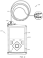
FIG. 2 depicts a plan view of an exemplary embodiment of a fluid infusion device suitable for use in the infusion system ofFIG. 1 ; -
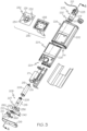
FIG. 3 is an exploded perspective view of the fluid infusion device ofFIG. 2 ; -
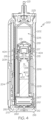
FIG. 4 is a cross-sectional view of the fluid infusion device ofFIGS. 2-3 as viewed along line 4-4 inFIG. 3 when assembled with a reservoir inserted in the infusion device; -
FIG. 5 is a block diagram of an exemplary control system suitable for use in a fluid infusion device, such as the fluid infusion device ofFIG. 1 orFIG. 2 ; -
FIG. 6 is a block diagram of an exemplary pump control system suitable for use in the control system ofFIG. 5 ; -
FIG. 7 is a flow diagram of an exemplary adaptive ratio adjustment process suitable for use with the control system ofFIG. 5 in one or more exemplary embodiments; -
FIG. 8 is a graph depicting an exemplary relationship between an individual's post-prandial glucose level and time; -
FIG. 9 is a flow diagram of an exemplary sensitivity factor adjustment process suitable for use with the adaptive ratio adjustment process ofFIG. 7 in one or more exemplary embodiments; and -
FIG. 10 is a flow diagram of an exemplary conversion factor adjustment process suitable for use with the adaptive ratio adjustment process ofFIG. 7 in one or more exemplary embodiments. - The following detailed description is merely illustrative in nature and is not intended to limit the embodiments of the subject matter or the application and uses of such embodiments. As used herein, the word "exemplary" means "serving as an example, instance, or illustration." Any implementation described herein as exemplary is not necessarily to be construed as preferred or advantageous over other implementations. Furthermore, there is no intention to be bound by any expressed or implied theory presented in the preceding technical field, background, brief summary or the following detailed description.
- While the subject matter described herein can be implemented in any electronic device that includes a motor, exemplary embodiments described below are implemented in the form of medical devices, such as portable electronic medical devices. Although many different applications are possible, the following description focuses on a fluid infusion device (or infusion pump) as part of an infusion system deployment. For the sake of brevity, conventional techniques related to infusion system operation, insulin pump and/or infusion set operation, and other functional aspects of the systems (and the individual operating components of the systems) may not be described in detail here. Examples of infusion pumps may be of the type described in, but not limited to,
United States Patent numbers: 4,562,751 ;4,685,903 ;5,080,653 ;5,505,709 ;5,097,122 ;6,485,465 ;6,554,798 ;6,558,320 ;6,558,351 ;6,641,533 ;6,659,980 ;6,752,787 ;6,817,990 ;6,932,584 ; and7,621,893 ; each of which are herein incorporated by reference. - Embodiments of the subject matter described herein generally relate to fluid infusion devices including a motor or other actuation arrangement that is operable to linearly displace a plunger (or stopper) of a reservoir provided within the fluid infusion device to deliver a dosage of fluid, such as insulin, to the body of a user. Dosage commands that govern operation of the motor may be generated in an automated manner in accordance with the delivery control scheme associated with a particular operating mode, and the dosage commands may be generated in a manner that is influenced by a current (or most recent) measurement of a physiological condition in the body of the user. For example, in a closed-loop operating mode, dosage commands may be generated based on a difference between a current (or most recent) measurement of the interstitial fluid glucose level in the body of the user and a target (or reference) glucose value. In this regard, the rate of infusion may vary as the difference between a current measurement value and the target measurement value fluctuates. For purposes of explanation, the subject matter is described herein in the context of the infused fluid being insulin for regulating a glucose level of a user (or patient); however, it should be appreciated that many other fluids may be administered through infusion, and the subject matter described herein is not necessarily limited to use with insulin.
- Often a user (or patient) manually operates an infusion device to deliver a bolus of insulin at mealtime (often referred to as a "meal bolus" or "correction bolus"), which is intended to compensate for or otherwise mitigate a potential spike in the user's glucose level attributable to the amount of carbohydrates consumed during the meal. The user manually inputs the amount of carbohydrates being consumed, which, in turn are converted to a corresponding amount of insulin units using a carbohydrate conversion ratio, which may be maintained by the infusion device. The carbohydrate conversion ratio can be specific to that individual, and can be determined by the user or the user's care provider using any of a number of potential techniques or methodologies before being stored onboard the infusion device for use in subsequently administering meal boluses.
- As described in greater detail below, primarily in the context of
FIGS. 7-10 , in exemplary embodiments described herein, measurements of a user's glucose level are monitored and analyzed after a bolus of insulin is delivered, and based on the user's glucose measurements, a residual value representing a deviation from the user's pre-bolus and pre-meal glucose level after metabolization of the bolus and the meal is identified. In this regard, the residual glucose value represents an amount, in terms of the user's glucose level, that the bolus overcompensated or undercompensated for the amount of carbohydrates consumed by the user during the meal, that is, the difference between the user's post-prandial glucose settling value and the user's pre-prandial glucose value. Using the residual glucose value, the user's carbohydrate ratio is adjusted to compensate for the residual value. For example, when the residual glucose value is positive and thereby indicative of an insufficient bolus amount, the user's carbohydrate ratio is updated to a lower value configured to increase subsequent meal bolus amounts (on a per carbohydrate unit basis). Conversely, when the residual glucose value is negative and thereby indicative of an excessive bolus amount, the user's carbohydrate ratio is updated to a higher value configured to decrease subsequent meal bolus amounts (on a per carbohydrate unit basis). - By virtue of the carbohydrate ratio being adaptively adjusted to compensate for the residual glucose level, subsequent meal boluses may more effectively compensate for consumed carbohydrates and mitigate glucose excursions attributable to meal consumption, over time resulting in a post-prandial glucose level substantially equal to the pre-prandial glucose level as the carbohydrate ratio converges towards a stable value. Some embodiments may employ different context-sensitive patient-specific carbohydrate ratios associated with different times of the day, different days of the week, or other different bolus contexts, with those context-sensitive patient-specific carbohydrate ratios also being adaptively and dynamically adjusted based on boluses having the same context, which, in turn, may further improve the effectiveness of meal boluses associated with the same bolus context (e.g., time of day, day of week, etc.).
- As described in the context of
FIG. 9 , in one or more embodiments, the user's carbohydrate ratio is scaled by an adjustment factor corresponding to the ratio of the delivered meal bolus amount to the sum of the delivered meal bolus amount and a residual amount of insulin corresponding to the residual glucose value. In such embodiments, the residual glucose value is converted to a corresponding residual amount of units of insulin using the user's insulin sensitivity factor, with the residual insulin amount then being used to increase or decrease the carbohydrate ratio inversely to the magnitude of the residual insulin amount (e.g., a negative residual insulin amount increases the carbohydrate ratio and a positive residual insulin amount decreases the carbohydrate ratio). - In other embodiments described in the context of
FIG. 10 , the user's carbohydrate ratio is scaled by an adjustment factor corresponding to the ratio of a difference between the input meal carbohydrate amount and a residual carbohydrate amount relative to the input meal carbohydrate amount. In such embodiments, the residual glucose value is converted to a corresponding residual amount of carbohydrates for which the delivered bolus overcompensated (in the case of a negative value) or undercompensated for (in the case of a positive value) of insulin using the user's insulin sensitivity factor. The residual carbohydrate amount is then used to increase or decrease the carbohydrate ratio inversely to the magnitude of the residual insulin carbohydrate (e.g., a negative residual carbohydrate amount increases the carbohydrate ratio and a positive residual insulin amount decreases the carbohydrate ratio). - Turning now to
FIG. 1 , one exemplary embodiment of aninfusion system 100 includes, without limitation, a fluid infusion device (or infusion pump) 102, asensing arrangement 104, a command control device (CCD) 106, and acomputer 108. The components of aninfusion system 100 may be realized using different platforms, designs, and configurations, and the embodiment shown inFIG. 1 is not exhaustive or limiting. In practice, theinfusion device 102 and thesensing arrangement 104 are secured at desired locations on the body of a user (or patient), as illustrated inFIG. 1 . In this regard, the locations at which theinfusion device 102 and thesensing arrangement 104 are secured to the body of the user inFIG. 1 are provided only as a representative, non-limiting, example. The elements of theinfusion system 100 may be similar to those described inUnited States Patent No. 8,674,288 , the subject matter of which is hereby incorporated by reference in its entirety. - In the illustrated embodiment of
FIG. 1 , theinfusion device 102 is designed as a portable medical device suitable for infusing a fluid, a liquid, a gel, or other agent into the body of a user. In exemplary embodiments, the infused fluid is insulin, although many other fluids may be administered through infusion such as, but not limited to, HIV drugs, drugs to treat pulmonary hypertension, iron chelation drugs, pain medications, anti-cancer treatments, medications, vitamins, hormones, or the like. In some embodiments, the fluid may include a nutritional supplement, a dye, a tracing medium, a saline medium, a hydration medium, or the like. - The
sensing arrangement 104 generally represents the components of theinfusion system 100 configured to sense, detect, measure or otherwise quantify a condition of the user, and may include a sensor, a monitor, or the like, for providing data indicative of the condition that is sensed, detected, measured or otherwise monitored by the sensing arrangement. In this regard, thesensing arrangement 104 may include electronics and enzymes reactive to a biological or physiological condition of the user, such as a blood glucose level, or the like, and provide data indicative of the blood glucose level to theinfusion device 102, theCCD 106 and/or thecomputer 108. For example, theinfusion device 102, theCCD 106 and/or thecomputer 108 may include a display for presenting information or data to the user based on the sensor data received from thesensing arrangement 104, such as, for example, a current glucose level of the user, a graph or chart of the user's glucose level versus time, device status indicators, alert messages, or the like. In other embodiments, theinfusion device 102, theCCD 106 and/or thecomputer 108 may include electronics and software that are configured to analyze sensor data and operate theinfusion device 102 to deliver fluid to the body of the user based on the sensor data and/or preprogrammed delivery routines. Thus, in exemplary embodiments, one or more of theinfusion device 102, thesensing arrangement 104, theCCD 106, and/or thecomputer 108 includes a transmitter, a receiver, and/or other transceiver electronics that allow for communication with other components of theinfusion system 100, so that thesensing arrangement 104 may transmit sensor data or monitor data to one or more of theinfusion device 102, theCCD 106 and/or thecomputer 108. - Still referring to
FIG. 1 , in various embodiments, thesensing arrangement 104 may be secured to the body of the user or embedded in the body of the user at a location that is remote from the location at which theinfusion device 102 is secured to the body of the user. In various other embodiments, thesensing arrangement 104 may be incorporated within theinfusion device 102. In other embodiments, thesensing arrangement 104 may be separate and apart from theinfusion device 102, and may be, for example, part of theCCD 106. In such embodiments, thesensing arrangement 104 may be configured to receive a biological sample, analyte, or the like, to measure a condition of the user. - In various embodiments, the
CCD 106 and/or thecomputer 108 may include electronics and other components configured to perform processing, delivery routine storage, and to control theinfusion device 102 in a manner that is influenced by sensor data measured by and/or received from thesensing arrangement 104. By including control functions in theCCD 106 and/or thecomputer 108, theinfusion device 102 may be made with more simplified electronics. However, in other embodiments, theinfusion device 102 may include all control functions, and may operate without theCCD 106 and/or thecomputer 108. In various embodiments, theCCD 106 may be a portable electronic device. In addition, in various embodiments, theinfusion device 102 and/or thesensing arrangement 104 may be configured to transmit data to theCCD 106 and/or thecomputer 108 for display or processing of the data by theCCD 106 and/or thecomputer 108. - In some embodiments, the
CCD 106 and/or thecomputer 108 may provide information to the user that facilitates the user's subsequent use of theinfusion device 102. For example, theCCD 106 may provide information to the user to allow the user to determine the rate or dose of medication to be administered into the user's body. In other embodiments, theCCD 106 may provide information to theinfusion device 102 to autonomously control the rate or dose of medication administered into the body of the user. In some embodiments, thesensing arrangement 104 may be integrated into theCCD 106. Such embodiments may allow the user to monitor a condition by providing, for example, a sample of his or her blood to thesensing arrangement 104 to assess his or her condition. In some embodiments, thesensing arrangement 104 and theCCD 106 may be used for determining glucose levels in the blood and/or body fluids of the user without the use of, or necessity of, a wire or cable connection between theinfusion device 102 and thesensing arrangement 104 and/or theCCD 106. - In one or more exemplary embodiments, the
sensing arrangement 104 and/or theinfusion device 102 are cooperatively configured to utilize a closed-loop system for delivering fluid to the user. Examples of sensing devices and/or infusion pumps utilizing closed-loop systems may be found at, but are not limited to, the followingUnited States patent numbers: 6,088,608 ,6,119,028 ,6,589,229 ,6,740,072 ,6,827,702 ,7,323,142 , and7,402,153 , all of which are incorporated herein by reference in their entirety. In such embodiments, thesensing arrangement 104 is configured to sense or measure a condition of the user, such as, blood glucose level or the like. Theinfusion device 102 is configured to deliver fluid in response to the condition sensed by thesensing arrangement 104. In turn, thesensing arrangement 104 continues to sense or otherwise quantify a current condition of the user, thereby allowing theinfusion device 102 to deliver fluid continuously in response to the condition currently (or most recently) sensed by thesensing arrangement 104 indefinitely. In some embodiments, thesensing arrangement 104 and/or theinfusion device 102 may be configured to utilize the closed-loop system only for a portion of the day, for example only when the user is asleep or awake. -
FIGS. 2-4 depict one exemplary embodiment of a fluid infusion device 200 (or alternatively, infusion pump) suitable for use in an infusion system, such as, for example, asinfusion device 102 in theinfusion system 100 ofFIG. 1 . Thefluid infusion device 200 is a portable medical device designed to be carried or worn by a patient (or user), and thefluid infusion device 200 may leverage any number of conventional features, components, elements, and characteristics of existing fluid infusion devices, such as, for example, some of the features, components, elements, and/or characteristics described inUnited States Patent numbers 6,485,465 and7,621,893 . It should be appreciated thatFIGS. 2-4 depict some aspects of theinfusion device 200 in a simplified manner; in practice, theinfusion device 200 could include additional elements, features, or components that are not shown or described in detail herein. - As best illustrated in
FIGS. 2-3 , the illustrated embodiment of thefluid infusion device 200 includes ahousing 202 adapted to receive a fluid-containingreservoir 205. Anopening 220 in thehousing 202 accommodates a fitting 223 (or cap) for thereservoir 205, with the fitting 223 being configured to mate or otherwise interface withtubing 221 of an infusion set 225 that provides a fluid path to/from the body of the user. In this manner, fluid communication from the interior of thereservoir 205 to the user is established via thetubing 221. The illustratedfluid infusion device 200 includes a human-machine interface (HMI) 230 (or user interface) that includeselements display element 226, such as a liquid crystal display (LCD) or another suitable display element, that can be used to present various types of information or data to the user, such as, without limitation: the current glucose level of the patient; the time; a graph or chart of the patient's glucose level versus time; device status indicators; etc. - The
housing 202 is formed from a substantially rigid material having ahollow interior 214 adapted to allow anelectronics assembly 204, a sliding member (or slide) 206, adrive system 208, asensor assembly 210, and a drivesystem capping member 212 to be disposed therein in addition to thereservoir 205, with the contents of thehousing 202 being enclosed by ahousing capping member 216. Theopening 220, theslide 206, and thedrive system 208 are coaxially aligned in an axial direction (indicated by arrow 218), whereby thedrive system 208 facilitates linear displacement of theslide 206 in theaxial direction 218 to dispense fluid from the reservoir 205 (after thereservoir 205 has been inserted into opening 220), with thesensor assembly 210 being configured to measure axial forces (e.g., forces aligned with the axial direction 218) exerted on thesensor assembly 210 responsive to operating thedrive system 208 to displace theslide 206. In various embodiments, thesensor assembly 210 may be utilized to detect one or more of the following: an occlusion in a fluid path that slows, prevents, or otherwise degrades fluid delivery from thereservoir 205 to a user's body; when thereservoir 205 is empty; when theslide 206 is properly seated with thereservoir 205; when a fluid dose has been delivered; when theinfusion pump 200 is subjected to shock or vibration; when theinfusion pump 200 requires maintenance. - Depending on the embodiment, the fluid-containing
reservoir 205 may be realized as a syringe, a vial, a cartridge, a bag, or the like. In certain embodiments, the infused fluid is insulin, although many other fluids may be administered through infusion such as, but not limited to, HIV drugs, drugs to treat pulmonary hypertension, iron chelation drugs, pain medications, anti-cancer treatments, medications, vitamins, hormones, or the like. As best illustrated inFIGS. 3-4 , thereservoir 205 typically includes areservoir barrel 219 that contains the fluid and is concentrically and/or coaxially aligned with the slide 206 (e.g., in the axial direction 218) when thereservoir 205 is inserted into theinfusion pump 200. The end of thereservoir 205 proximate theopening 220 may include or otherwise mate with the fitting 223, which secures thereservoir 205 in thehousing 202 and prevents displacement of thereservoir 205 in theaxial direction 218 with respect to thehousing 202 after thereservoir 205 is inserted into thehousing 202. As described above, the fitting 223 extends from (or through) theopening 220 of thehousing 202 and mates withtubing 221 to establish fluid communication from the interior of the reservoir 205 (e.g., reservoir barrel 219) to the user via thetubing 221 and infusion set 225. The opposing end of thereservoir 205 proximate theslide 206 includes a plunger 217 (or stopper) positioned to push fluid from inside thebarrel 219 of thereservoir 205 along a fluid path throughtubing 221 to a user. Theslide 206 is configured to mechanically couple or otherwise engage with theplunger 217, thereby becoming seated with theplunger 217 and/orreservoir 205. Fluid is forced from thereservoir 205 viatubing 221 as thedrive system 208 is operated to displace theslide 206 in theaxial direction 218 toward theopening 220 in thehousing 202. - In the illustrated embodiment of
FIGS. 3-4 , thedrive system 208 includes amotor assembly 207 and adrive screw 209. Themotor assembly 207 includes a motor that is coupled to drive train components of thedrive system 208 that are configured to convert rotational motor motion to a translational displacement of theslide 206 in theaxial direction 218, and thereby engaging and displacing theplunger 217 of thereservoir 205 in theaxial direction 218. In some embodiments, themotor assembly 207 may also be powered to translate theslide 206 in the opposing direction (e.g., the direction opposite direction 218) to retract and/or detach from thereservoir 205 to allow thereservoir 205 to be replaced. In exemplary embodiments, themotor assembly 207 includes a brushless DC (BLDC) motor having one or more permanent magnets mounted, affixed, or otherwise disposed on its rotor. However, the subject matter described herein is not necessarily limited to use with BLDC motors, and in alternative embodiments, the motor may be realized as a solenoid motor, an AC motor, a stepper motor, a piezoelectric caterpillar drive, a shape memory actuator drive, an electrochemical gas cell, a thermally driven gas cell, a bimetallic actuator, or the like. The drive train components may comprise one or more lead screws, cams, ratchets, jacks, pulleys, pawls, clamps, gears, nuts, slides, bearings, levers, beams, stoppers, plungers, sliders, brackets, guides, bearings, supports, bellows, caps, diaphragms, bags, heaters, or the like. In this regard, although the illustrated embodiment of the infusion pump utilizes a coaxially aligned drive train, the motor could be arranged in an offset or otherwise non-coaxial manner, relative to the longitudinal axis of thereservoir 205. - As best shown in
FIG. 4 , thedrive screw 209 mates withthreads 402 internal to theslide 206. When themotor assembly 207 is powered and operated, thedrive screw 209 rotates, and theslide 206 is forced to translate in theaxial direction 218. In an exemplary embodiment, theinfusion pump 200 includes asleeve 211 to prevent theslide 206 from rotating when thedrive screw 209 of thedrive system 208 rotates. Thus, rotation of thedrive screw 209 causes theslide 206 to extend or retract relative to thedrive motor assembly 207. When the fluid infusion device is assembled and operational, theslide 206 contacts theplunger 217 to engage thereservoir 205 and control delivery of fluid from theinfusion pump 200. In an exemplary embodiment, theshoulder portion 215 of theslide 206 contacts or otherwise engages theplunger 217 to displace theplunger 217 in theaxial direction 218. In alternative embodiments, theslide 206 may include a threadedtip 213 capable of being detachably engaged withinternal threads 404 on theplunger 217 of thereservoir 205, as described in detail inUnited States patent numbers 6,248,093 and6,485,465 , which are incorporated by reference herein. - As illustrated in
FIG. 3 , theelectronics assembly 204 includescontrol electronics 224 coupled to thedisplay element 226, with thehousing 202 including atransparent window portion 228 that is aligned with thedisplay element 226 to allow thedisplay 226 to be viewed by the user when theelectronics assembly 204 is disposed within theinterior 214 of thehousing 202. Thecontrol electronics 224 generally represent the hardware, firmware, processing logic and/or software (or combinations thereof) configured to control operation of themotor assembly 207 and/ordrive system 208, as described in greater detail below in the context ofFIG. 5 . Whether such functionality is implemented as hardware, firmware, a state machine, or software depends upon the particular application and design constraints imposed on the embodiment. Those familiar with the concepts described here may implement such functionality in a suitable manner for each particular application, but such implementation decisions should not be interpreted as being restrictive or limiting. In an exemplary embodiment, thecontrol electronics 224 includes one or more programmable controllers that may be programmed to control operation of theinfusion pump 200. - The
motor assembly 207 includes one or moreelectrical leads 236 adapted to be electrically coupled to theelectronics assembly 204 to establish communication between thecontrol electronics 224 and themotor assembly 207. In response to command signals from thecontrol electronics 224 that operate a motor driver (e.g., a power converter) to regulate the amount of power supplied to the motor from a power supply, the motor actuates the drive train components of thedrive system 208 to displace theslide 206 in theaxial direction 218 to force fluid from thereservoir 205 along a fluid path (includingtubing 221 and an infusion set), thereby administering doses of the fluid contained in thereservoir 205 into the user's body. Preferably, the power supply is realized as one or more batteries contained within thehousing 202. Alternatively, the power supply may be a solar panel, capacitor, AC or DC power supplied through a power cord, or the like. In some embodiments, thecontrol electronics 224 may operate the motor of themotor assembly 207 and/ordrive system 208 in a stepwise manner, typically on an intermittent basis; to administer discrete precise doses of the fluid to the user according to programmed delivery profiles. - Referring to
FIGS. 2-4 , as described above, theuser interface 230 includes HMI elements, such asbuttons 232 and adirectional pad 234, that are formed on agraphic keypad overlay 231 that overlies akeypad assembly 233, which includes features corresponding to thebuttons 232,directional pad 234 or other user interface items indicated by thegraphic keypad overlay 231. When assembled, thekeypad assembly 233 is coupled to thecontrol electronics 224, thereby allowing theHMI elements control electronics 224 and control operation of theinfusion pump 200, for example, to administer a bolus of insulin, to change therapy settings, to change user preferences, to select display features, to set or disable alarms and reminders, and the like. In this regard, thecontrol electronics 224 maintains and/or provides information to thedisplay 226 regarding program parameters, delivery profiles, pump operation, alarms, warnings, statuses, or the like, which may be adjusted using theHMI elements HMI elements display 226 may be realized as a touch screen or touch-sensitive display, and in such embodiments, the features and/or functionality of theHMI elements display 226 and theHMI 230 may not be present. In some embodiments, theelectronics assembly 204 may also include alert generating elements coupled to thecontrol electronics 224 and suitably configured to generate one or more types of feedback, such as, without limitation: audible feedback; visual feedback; haptic (physical) feedback; or the like. - Referring to
FIGS. 3-4 , in accordance with one or more embodiments, thesensor assembly 210 includes aback plate structure 250 and aloading element 260. Theloading element 260 is disposed between the cappingmember 212 and abeam structure 270 that includes one or more beams having sensing elements disposed thereon that are influenced by compressive force applied to thesensor assembly 210 that deflects the one or more beams, as described in greater detail inUnited States Patent No. 8,474,332 , which is incorporated by reference herein. In exemplary embodiments, theback plate structure 250 is affixed, adhered, mounted, or otherwise mechanically coupled to thebottom surface 238 of thedrive system 208 such that theback plate structure 250 resides between thebottom surface 238 of thedrive system 208 and thehousing cap 216. The drivesystem capping member 212 is contoured to accommodate and conform to the bottom of thesensor assembly 210 and thedrive system 208. The drivesystem capping member 212 may be affixed to the interior of thehousing 202 to prevent displacement of thesensor assembly 210 in the direction opposite the direction of force provided by the drive system 208 (e.g., the direction opposite direction 218). Thus, thesensor assembly 210 is positioned between themotor assembly 207 and secured by the cappingmember 212, which prevents displacement of thesensor assembly 210 in a downward direction opposite the direction ofarrow 218, such that thesensor assembly 210 is subjected to a reactionary compressive force when thedrive system 208 and/ormotor assembly 207 is operated to displace theslide 206 in theaxial direction 218 in opposition to the fluid pressure in thereservoir 205. Under normal operating conditions, the compressive force applied to thesensor assembly 210 is correlated with the fluid pressure in thereservoir 205. As shown,electrical leads 240 are adapted to electrically couple the sensing elements of thesensor assembly 210 to theelectronics assembly 204 to establish communication to thecontrol electronics 224, wherein thecontrol electronics 224 are configured to measure, receive, or otherwise obtain electrical signals from the sensing elements of thesensor assembly 210 that are indicative of the force applied by thedrive system 208 in theaxial direction 218. -
FIG. 5 depicts an exemplary embodiment of acontrol system 500 suitable for use with aninfusion device 502, such as theinfusion device 102 inFIG. 1 or theinfusion device 200 ofFIG. 2 . Thecontrol system 500 is capable of controlling or otherwise regulating a physiological condition in thebody 501 of a user to a desired (or target) value or otherwise maintain the condition within a range of acceptable values in an automated or autonomous manner. In one or more exemplary embodiments, the condition being regulated is sensed, detected, measured or otherwise quantified by a sensing arrangement 504 (e.g., sensing arrangement 104) communicatively coupled to theinfusion device 502. However, it should be noted that in alternative embodiments, the condition being regulated by thecontrol system 500 may be correlative to the measured values obtained by thesensing arrangement 504. That said, for clarity and purposes of explanation, the subject matter may be described herein in the context of thesensing arrangement 504 being realized as a glucose sensing arrangement that senses, detects, measures or otherwise quantifies the user's glucose level, which is being regulated in thebody 501 of the user by thecontrol system 500. - In exemplary embodiments, the
sensing arrangement 504 includes one or more interstitial glucose sensing elements that generate or otherwise output electrical signals having a signal characteristic that is correlative to, influenced by, or otherwise indicative of the relative interstitial fluid glucose level in thebody 501 of the user. The output electrical signals are filtered or otherwise processed to obtain a measurement value indicative of the user's interstitial fluid glucose level. In exemplary embodiments, ablood glucose meter 530, such as a finger stick device, is utilized to directly sense, detect, measure or otherwise quantify the blood glucose in thebody 501 of the user. In this regard, theblood glucose meter 530 outputs or otherwise provides a measured blood glucose value that may be utilized as a reference measurement for calibrating thesensing arrangement 504 and converting a measurement value indicative of the user's interstitial fluid glucose level into a corresponding calibrated blood glucose value. For purposes of explanation, the calibrated blood glucose value calculated based on the electrical signals output by the sensing element(s) of thesensing arrangement 504 may alternatively be referred to herein as the sensor glucose value, the sensed glucose value, or variants thereof. - In the illustrated embodiment, the
pump control system 520 generally represents the electronics and other components of theinfusion device 502 that control operation of thefluid infusion device 502 according to a desired infusion delivery program in a manner that is influenced by the sensed glucose value indicative of a current glucose level in thebody 501 of the user. For example, to support a closed-loop operating mode, thepump control system 520 maintains, receives, or otherwise obtains a target or commanded glucose value, and automatically generates or otherwise determines dosage commands for operating an actuation arrangement, such as amotor 507, to displace theplunger 517 and deliver insulin to thebody 501 of the user based on the difference between a sensed glucose value and the target glucose value. In other operating modes, thepump control system 520 may generate or otherwise determine dosage commands configured to maintain the sensed glucose value below an upper glucose limit, above a lower glucose limit, or otherwise within a desired range of glucose values. In practice, theinfusion device 502 may store or otherwise maintain the target value, upper and/or lower glucose limit(s), and/or other glucose threshold value(s) in a data storage element accessible to thepump control system 520. - The target glucose value and other threshold glucose values may be received from an external component (e.g.,
CCD 106 and/or computing device 108) or be input by a user via auser interface element 540 associated with theinfusion device 502. In practice, the one or more user interface element(s) 540 associated with theinfusion device 502 typically include at least one input user interface element, such as, for example, a button, a keypad, a keyboard, a knob, a joystick, a mouse, a touch panel, a touchscreen, a microphone or another audio input device, and/or the like. Additionally, the one or more user interface element(s) 540 include at least one output user interface element, such as, for example, a display element (e.g., a light-emitting diode or the like), a display device (e.g., a liquid crystal display or the like), a speaker or another audio output device, a haptic feedback device, or the like, for providing notifications or other information to the user. It should be noted that althoughFIG. 5 depicts the user interface element(s) 540 as being separate from theinfusion device 502, in practice, one or more of the user interface element(s) 540 may be integrated with theinfusion device 502. Furthermore, in some embodiments, one or more user interface element(s) 540 are integrated with thesensing arrangement 504 in addition to and/or in alternative to the user interface element(s) 540 integrated with theinfusion device 502. The user interface element(s) 540 may be manipulated by the user to operate theinfusion device 502 to deliver correction boluses, adjust target and/or threshold values, modify the delivery control scheme or operating mode, and the like, as desired. - Still referring to
FIG. 5 , in the illustrated embodiment, theinfusion device 502 includes amotor control module 512 coupled to a motor 507 (e.g., motor assembly 207) that is operable to displace a plunger 517 (e.g., plunger 217) in a reservoir (e.g., reservoir 205) and provide a desired amount of fluid to thebody 501 of a user. In this regard, displacement of theplunger 517 results in the delivery of a fluid that is capable of influencing the condition in thebody 501 of the user to thebody 501 of the user via a fluid delivery path (e.g., viatubing 221 of an infusion set 225). Amotor driver module 514 is coupled between anenergy source 503 and themotor 507. Themotor control module 512 is coupled to themotor driver module 514, and themotor control module 512 generates or otherwise provides command signals that operate themotor driver module 514 to provide current (or power) from theenergy source 503 to themotor 507 to displace theplunger 517 in response to receiving, from apump control system 520, a dosage command indicative of the desired amount of fluid to be delivered. - In exemplary embodiments, the
energy source 503 is realized as a battery housed within the infusion device 502 (e.g., within housing 202) that provides direct current (DC) power. In this regard, themotor driver module 514 generally represents the combination of circuitry, hardware and/or other electrical components configured to convert or otherwise transfer DC power provided by theenergy source 503 into alternating electrical signals applied to respective phases of the stator windings of themotor 507 that result in current flowing through the stator windings that generates a stator magnetic field and causes the rotor of themotor 507 to rotate. Themotor control module 512 is configured to receive or otherwise obtain a commanded dosage from thepump control system 520, convert the commanded dosage to a commanded translational displacement of theplunger 517, and command, signal, or otherwise operate themotor driver module 514 to cause the rotor of themotor 507 to rotate by an amount that produces the commanded translational displacement of theplunger 517. For example, themotor control module 512 may determine an amount of rotation of the rotor required to produce translational displacement of theplunger 517 that achieves the commanded dosage received from thepump control system 520. Based on the current rotational position (or orientation) of the rotor with respect to the stator that is indicated by the output of therotor sensing arrangement 516, themotor control module 512 determines the appropriate sequence of alternating electrical signals to be applied to the respective phases of the stator windings that should rotate the rotor by the determined amount of rotation from its current position (or orientation). In embodiments where themotor 507 is realized as a BLDC motor, the alternating electrical signals commutate the respective phases of the stator windings at the appropriate orientation of the rotor magnetic poles with respect to the stator and in the appropriate order to provide a rotating stator magnetic field that rotates the rotor in the desired direction. Thereafter, themotor control module 512 operates themotor driver module 514 to apply the determined alternating electrical signals (e.g., the command signals) to the stator windings of themotor 507 to achieve the desired delivery of fluid to the user. - When the
motor control module 512 is operating themotor driver module 514, current flows from theenergy source 503 through the stator windings of themotor 507 to produce a stator magnetic field that interacts with the rotor magnetic field. In some embodiments, after themotor control module 512 operates themotor driver module 514 and/ormotor 507 to achieve the commanded dosage, themotor control module 512 ceases operating themotor driver module 514 and/ormotor 507 until a subsequent dosage command is received. In this regard, themotor driver module 514 and themotor 507 enter an idle state during which themotor driver module 514 effectively disconnects or isolates the stator windings of themotor 507 from theenergy source 503. In other words, current does not flow from theenergy source 503 through the stator windings of themotor 507 when themotor 507 is idle, and thus, themotor 507 does not consume power from theenergy source 503 in the idle state, thereby improving efficiency. - Depending on the embodiment, the
motor control module 512 may be implemented or realized with a general purpose processor, a microprocessor, a controller, a microcontroller, a state machine, a content addressable memory, an application specific integrated circuit, a field programmable gate array, any suitable programmable logic device, discrete gate or transistor logic, discrete hardware components, or any combination thereof, designed to perform the functions described herein. In exemplary embodiments, themotor control module 512 includes or otherwise accesses a data storage element or memory, including any sort of random access memory (RAM), read only memory (ROM), flash memory, registers, hard disks, removable disks, magnetic or optical mass storage, or any other short or long term storage media or other non-transitory computer-readable medium, which is capable of storing programming instructions for execution by themotor control module 512. The computer-executable programming instructions, when read and executed by themotor control module 512, cause themotor control module 512 to perform or otherwise support the tasks, operations, functions, and processes described herein. - It should be appreciated that
FIG. 5 is a simplified representation of theinfusion device 502 for purposes of explanation and is not intended to limit the subject matter described herein in any way. In this regard, depending on the embodiment, some features and/or functionality of thesensing arrangement 504 may implemented by or otherwise integrated into thepump control system 520, or vice versa. Similarly, in practice, the features and/or functionality of themotor control module 512 may implemented by or otherwise integrated into thepump control system 520, or vice versa. Furthermore, the features and/or functionality of thepump control system 520 may be implemented bycontrol electronics 224 located in thefluid infusion device 200, 400, while in alternative embodiments, thepump control system 520 may be implemented by a remote computing device that is physically distinct and/or separate from theinfusion device 502, such as, for example, theCCD 106 or thecomputing device 108. -
FIG. 6 depicts an exemplary embodiment of apump control system 600 suitable for use as thepump control system 520 inFIG. 5 in accordance with one or more embodiments. The illustratedpump control system 600 includes, without limitation, apump control module 602, acommunications interface 604, and a data storage element (or memory) 606. Thepump control module 602 is coupled to thecommunications interface 604 and thememory 606, and thepump control module 602 is suitably configured to support the operations, tasks, and/or processes described herein. In exemplary embodiments, thepump control module 602 is also coupled to one or more user interface elements 608 (e.g.,user interface 230, 540) for receiving user input and providing notifications, alerts, or other therapy information to the user. AlthoughFIG. 6 depicts theuser interface element 608 as being separate from thepump control system 600, in various alternative embodiments, theuser interface element 608 may be integrated with the pump control system 600 (e.g., as part of theinfusion device 200, 502), thesensing arrangement 504 or another element of an infusion system 100 (e.g., thecomputer 108 or CCD 106). - Referring to
FIG. 6 and with reference toFIG. 5 , thecommunications interface 604 generally represents the hardware, circuitry, logic, firmware and/or other components of thepump control system 600 that are coupled to thepump control module 602 and configured to support communications between thepump control system 600 and thesensing arrangement 504. In this regard, thecommunications interface 604 may include or otherwise be coupled to one or more transceiver modules capable of supporting wireless communications between thepump control system sensing arrangement 504 or anotherelectronic device infusion system 100. In other embodiments, thecommunications interface 604 may be configured to support wired communications to/from thesensing arrangement 504. - The
pump control module 602 generally represents the hardware, circuitry, logic, firmware and/or other component of thepump control system 600 that is coupled to thecommunications interface 604 and configured to determine dosage commands for operating the motor 506 to deliver fluid to thebody 501 based on data received from thesensing arrangement 504 and perform various additional tasks, operations, functions and/or operations described herein. For example, in exemplary embodiments,pump control module 602 implements or otherwise executes acommand generation application 610 that supports one or more autonomous operating modes and calculates or otherwise determines dosage commands for operating the motor 506 of theinfusion device 502 in an autonomous operating mode based at least in part on a current measurement value for a condition in thebody 501 of the user. For example, in a closed-loop operating mode, thecommand generation application 610 may determine a dosage command for operating the motor 506 to deliver insulin to thebody 501 of the user based at least in part on the current glucose measurement value most recently received from thesensing arrangement 504 to regulate the user's blood glucose level to a target reference glucose value. - Additionally, the
command generation application 610 may generate dosage commands for boluses that are manually-initiated or otherwise instructed by a user via auser interface element 608. For example, independent of the operating mode being implemented, thecommand generation application 610 may determine a dosage command for operating the motor 506 to deliver a bolus of insulin to thebody 501 of the user that corresponds to a correction bolus or meal bolus amount selected or otherwise indicated by the user via theuser interface element user interface element command generation application 610 receives the input carbohydrate amount (CHO) and retrieves or otherwise obtains a carbohydrate conversion ratio associated with the user from a data storage element 606 (or memory), which, in turn, is utilized to convert the input carbohydrate amount into a corresponding bolus amount of insulin units using the equation
memory 606 stores a plurality of different patient-specific carbohydrate ratios, with each carbohydrate ratio being associated with a particular bolus context, such as, for example, a particular time of day (e.g., a 6 AM - 10 AM time window, a 10 AM - 2 PM time window, and the like). Additionally, the carbohydrate ratios may be associated with particular days of the week, or other variables or parameters that may be input by the user or otherwise detected automatically, such as, for example, whether or not the user has engaged in a particular type or duration of activity within a preceding time period. After determining the bolus dosage amount for the input carbohydrate amount using the appropriate carbohydrate ratio, thecommand generation application 610 may provide the commanded bolus dosage to themotor control module 512, which, in turn converts the commanded dosage into a corresponding displacement of theplunger 517 and operates themotor 507 accordingly to deliver the meal bolus with the commanded dosage amount. - As described in greater detail below in the context of
FIGS. 7-10 , in one or more embodiments, thecommand generation application 610 stores or otherwise maintains the most recently received sensor glucose measurement at the time of delivery of the meal bolus (e.g., the current pre-prandial glucose measurement value at the time of the bolus) and then monitors or otherwise analyzes subsequently received sensor glucose measurement values to detect or otherwise identify a post-prandial settling value after the user's glucose level recovers from a post-prandial peak value. In this regard, thecommand generation application 610 may identify a nadir or inflection point in the sensor glucose measurement values occurring after a peak value following the meal bolus delivery. Based on the difference between the post-prandial settling value and the stored pre-prandial value, thecommand generation application 610 determines a residual sensor glucose value (ΔSGR ) and updates the identified carbohydrate ratio used for the delivered meal bolus by adjusting the ratio in a manner that compensates for the residual sensor glucose value. In this regard, thecommand generation application 610 determines an adjustment scaling factor based on the residual sensor glucose value, which is then utilize to scale the carbohydrate ratio up or down as appropriate to compensate for the residual glucose value. The updated carbohydrate ratio value is then stored in thememory 606 in lieu of the previous value for the identified carbohydrate ratio associated with the current bolus context. Thus, for a subsequent meal bolus having the same bolus context, the updated carbohydrate ratio is utilized to determine that subsequent meal bolus, and the carbohydrate ratio may be further updated or adjusted based on the residual glucose value attributable to that subsequent meal bolus, and so on. In this manner, carbohydrate ratios are adaptively and dynamically adjusted towards a value that minimizes the post-prandial residual glucose value. - Still referring to
FIG. 6 , depending on the embodiment, thepump control module 602 may be implemented or realized with a general purpose processor, a microprocessor, a controller, a microcontroller, a state machine, a content addressable memory, an application specific integrated circuit, a field programmable gate array, any suitable programmable logic device, discrete gate or transistor logic, discrete hardware components, or any combination thereof, designed to perform the functions described herein. In this regard, the steps of a method or algorithm described in connection with the embodiments disclosed herein may be embodied directly in hardware, in firmware, in a software module executed by thepump control module 602, or in any practical combination thereof. In exemplary embodiments, thepump control module 602 includes or otherwise accesses the data storage element ormemory 606, which may be realized using any sort of non-transitory computer-readable medium capable of storing programming instructions for execution by thepump control module 602. The computer-executable programming instructions, when read and executed by thepump control module 602, cause thepump control module 602 to implement or otherwise generate thecommand generation application 610 and perform the tasks, operations, functions, and processes described in greater detail below. - It should be understood that
FIG. 6 is a simplified representation of apump control system 600 for purposes of explanation and is not intended to limit the subject matter described herein in any way. For example, in some embodiments, the features and/or functionality of themotor control module 512 may be implemented by or otherwise integrated into thepump control system 600 and/or thepump control module 602, for example, by thecommand generation application 610 converting the dosage command into a corresponding motor command, in which case, the separatemotor control module 512 may be absent from an embodiment of theinfusion device 502. -
FIG. 7 depicts an exemplaryratio adjustment process 700 suitable for implementation by a control system associated with a fluid infusion device, such as acontrol system infusion device 502, to automatically adjust the conversion ratio(s) used for determining bolus amounts in a manner that accounts for the effect of a preceding bolus when determining a subsequent bolus amount. The various tasks performed in connection with theratio adjustment process 700 may be performed by hardware, firmware, software executed by processing circuitry, or any combination thereof. For illustrative purposes, the following description refers to elements mentioned above in connection withFIGS. 1-6 . In practice, portions of theratio adjustment process 700 may be performed by different elements of thecontrol system 500, such as, for example, theinfusion device 502, thesensing arrangement 504, thepump control system pump control module 602, and/or thecommand generation application 610. It should be appreciated that theratio adjustment process 700 may include any number of additional or alternative tasks, the tasks need not be performed in the illustrated order and/or the tasks may be performed concurrently, and/or theratio adjustment process 700 may be incorporated into a more comprehensive procedure or process having additional functionality not described in detail herein. Moreover, one or more of the tasks shown and described in the context ofFIG. 7 could be omitted from a practical embodiment of theratio adjustment process 700 as long as the intended overall functionality remains intact. - Referring to
FIG. 7 with continued reference toFIGS. 1-6 , in exemplary embodiments, theratio adjustment process 700 is performed each time an infusion device is operated to deliver a manually-initiated bolus, such as a meal or correction bolus. Theratio adjustment process 700 begins by receiving, identifying, or otherwise obtaining the input carbohydrate estimate for a bolus to be delivered (task 702). In this regard, thepump control system user interface ratio adjustment process 700 also identifies or otherwise obtains the appropriate carbohydrate ratio utilized to convert the input carbohydrate amount to an amount of insulin units for the bolus (task 704). In this regard, theratio adjustment process 700 may identify or otherwise determine the current bolus context (e.g., the current time of day, the current day of the week, and the like), and then select or otherwise identify the carbohydrate ratio associated with the current bolus context. For example, a number of different carbohydrate ratios associated with the user may be stored in association with different time periods or windows during the day, with thepump control module 602 identifying or otherwise determining which time period encompasses the current infusion time and retrieving the corresponding carbohydrate ratio from thememory 606. - The
ratio adjustment process 700 also identifies or determines the amount of the bolus being delivered for the current infusion (task 706). For example, thepump control system 
- The
ratio adjustment process 700 monitors or otherwise analyzes the user's sensor glucose measurement values, and based thereon, identifies or otherwise determines a residual glucose value attributable to the delivered bolus (tasks 708, 710). In this regard, upon delivery of the bolus, thepump control system sensing arrangement 504 prior to delivery of the bolus as a pre-prandial reference glucose value (SG 0 ). Thereafter, thepump control system sensing arrangement 504 after to delivery of the bolus to identify a peak post-prandial glucose value. After the peak post-prandial glucose value is identified, thepump control system sensing arrangement 504 to identify a settling value or nadir in the glucose measurement values that represents the user's glucose level after metabolizing the consumed meal, the meal bolus, and any other insulin infused by any other autonomous control modes currently being implemented by thepump control system - In one or more embodiments, the
pump control system pump control system -
FIG. 8 is agraph 800 depicting an exemplary relationship of a user's sensor glucose values with respect to time after administering a bolus at or around the time of a meal. At an initial time (T 0), theinfusion device 502 delivers a meal bolus amount of insulin determined based on the input carbohydrate amount and the identified carbohydrate ratio for the current bolus context (e.g., a carbohydrate ratio associated with a time window encompassing T 0). Thepump control system sensing arrangement 504 at the bolus time (SG 0) as the pre-prandial sensor glucose reference value and monitors or otherwise analyzes subsequent sensor glucose values from thesensing arrangement 504 to detect or otherwise identify a peak sensor glucose value (SGPK ) at time TPK. Thereafter, in one or more embodiments, thepump control system pump control system pump control system - Referring again to
FIG. 7 , after identifying a residual glucose value, theratio adjustment process 700 calculates or otherwise determines an adjustment for the previously identified carbohydrate ratio used for the bolus that was delivered based on the residual glucose value and then updates the carbohydrate ratio stored or otherwise maintained onboard the infusion device to reflect the adjustment (tasks 712, 714). In exemplary embodiments, thepump control system memory 606 in lieu of the previous value for the identified carbohydrate ratio. - Thereafter, in response to receiving, via the
user interface pump control system 
ratio adjustment process 700 may be repeated in conjunction with the subsequent bolus to further update or adjust the carbohydrate ratio value in a manner that accounts for the residual glucose resulting from the subsequent bolus. In this manner, the carbohydrate ratio is adaptively and dynamically adjusted to account for the effectiveness of the preceding boluses, which, in turn, may reduce the residual glucose associated with subsequent boluses, thereby minimizing post-prandial glucose excursions and improving glucose regulation. -
FIG. 9 depicts an exemplary sensitivityfactor adjustment process 900 suitable for use in conjunction with theratio adjustment process 700 ofFIG. 7 (e.g., task 712) to update a carbohydrate ratio value based on a residual glucose value. The various tasks performed in connection with the sensitivityfactor adjustment process 900 may be performed by hardware, firmware, software executed by processing circuitry, or any combination thereof. For illustrative purposes, the following description refers to elements mentioned above in connection withFIGS. 1-6 . In practice, portions of the sensitivityfactor adjustment process 900 may be performed by different elements of thecontrol system 500, such as, for example, theinfusion device 502, thesensing arrangement 504, thepump control system pump control module 602, and/or thecommand generation application 610. It should be appreciated that the sensitivityfactor adjustment process 900 may include any number of additional or alternative tasks, the tasks need not be performed in the illustrated order and/or the tasks may be performed concurrently, and/or the sensitivityfactor adjustment process 900 may be incorporated into a more comprehensive procedure or process having additional functionality not described in detail herein. Moreover, one or more of the tasks shown and described in the context ofFIG. 9 could be omitted from a practical embodiment of the sensitivityfactor adjustment process 900 as long as the intended overall functionality remains intact. - The sensitivity
factor adjustment process 900 identifies or otherwise obtains a patient-specific insulin sensitivity factor and converts the residual sensor glucose value to a corresponding amount of units of insulin based on the insulin sensitivity factor (tasks 902, 904). In this regard, thepump control system 
infusion device 502 may maintain a plurality of different insulin sensitivity factors associated with different delivery contexts, where thepump control system - Thereafter, the sensitivity
factor adjustment process 900 adjusts, modifies, or otherwise updates the carbohydrate ratio used to determine the preceding bolus amount based on the residual insulin amount (task 906). In exemplary embodiments, thepump control system 

-
FIG. 10 depicts an exemplary conversion factor adjustment process 1000 suitable for use in conjunction with theratio adjustment process 700 ofFIG. 7 (e.g., task 712) to update a carbohydrate ratio value based on a residual glucose value. The various tasks performed in connection with the conversion factor adjustment process 1000 may be performed by hardware, firmware, software executed by processing circuitry, or any combination thereof. For illustrative purposes, the following description refers to elements mentioned above in connection withFIGS. 1-6 . In practice, portions of the conversion factor adjustment process 1000 may be performed by different elements of thecontrol system 500, such as, for example, theinfusion device 502, thesensing arrangement 504, thepump control system pump control module 602, and/or thecommand generation application 610. It should be appreciated that the conversion factor adjustment process 1000 may include any number of additional or alternative tasks, the tasks need not be performed in the illustrated order and/or the tasks may be performed concurrently, and/or the conversion factor adjustment process 1000 may be incorporated into a more comprehensive procedure or process having additional functionality not described in detail herein. Moreover, one or more of the tasks shown and described in the context ofFIG. 10 could be omitted from a practical embodiment of the conversion factor adjustment process 1000 as long as the intended overall functionality remains intact. - The conversion factor adjustment process 1000 identifies or otherwise obtains a carbohydrate conversion factor for the user and converts the residual sensor glucose value to a corresponding amount of carbohydrates based on the carbohydrate conversion factor (
tasks 1002, 1004). In this regard, the carbohydrate conversion factor represents the relationship between an increase in the user's glucose level per gram of carbohydrate consumed. After identifying the carbohydrate conversion factor, thepump control system 
- In one embodiment, a lookup table is stored or otherwise maintained onboard the infusion device 502 (e.g., in memory 606) that is utilized by the
pump control system pump control system infusion device 502 as part of the user's individual profile or settings. In a similar manner as described above in the context of the carbohydrate ratio and the insulin sensitivity factor, the carbohydrate conversion factor values in the lookup table may be further associated with different delivery contexts, where thepump control system user interface infusion device 502. In yet other embodiments, thepump control system - Still referring to
FIG. 10 , after determining the residual carbohydrate amount, the conversion factor adjustment process 1000 adjusts, modifies, or otherwise updates the carbohydrate ratio used to determine the preceding bolus amount based on the residual carbohydrate amount (task 1006). In exemplary embodiments, thepump control system 

- To briefly summarize, the subject matter described above allows for a patient-specific carbohydrate ratio to be dynamically adjusted to account for the patient's observed response to a preceding bolus and reduce the post-prandial glucose excursions exhibited after subsequent meals and boluses. In this regard, not only does the carbohydrate ratio adapt to reflect the individual's physiological response to a bolus and accompanying meal, but also can account for the individual habitually overestimating or underestimating the amount of carbohydrates associated with meals. Additionally, carbohydrate ratios may be associated with different delivery contexts, with adjustments being specific to a particular delivery context, thereby facilitating bolus amounts that reflect the individual's likely physiological response for the current circumstances (e.g., time of day, day of week, etc.).
- In some embodiments, the carbohydrate ratio may be preemptively adjusted before administration of a bolus based on historical trends in the adjustment factor with respect to the delivery context or other available information. For example, when boluses delivered at a particular time of day on a particular day of the week (e.g., evening meals on the weekend) exhibit an anomalous adjustment factor after the adjustment factor for other days of the week have converged towards a stable value (e.g., an adjustment factor value of approximately one), the carbohydrate ratio may be pre-adjusted to avoid a post-prandial glucose excursion. In this regard, the infusion device may store or otherwise maintain a set of the most recent adjustment factors and their associated context information which can be analyzed to detect or otherwise identify a bolus context for which pre-adjustment may be appropriate based on a difference in the adjustment factors for that bolus context deviating from other adjustment factors for a same or similar bolus context (e.g., the same time of day but different days of the week) by more than a threshold amount (e.g., a threshold percentage of the average adjustment factor value for that time of day). The pre-adjustment factor may also be determined based on the relationship between the anomalous adjustment factors and the reference adjustment factors (e.g., the average adjustment factor value for that time of day). Any residual glucose amount following the pre-adjustment may be utilized to modify or otherwise adjust the pre-adjustment factor for subsequent deliveries, or to otherwise adjust the carbohydrate ratio in a manner that accounts for the pre-adjustment. Similarly, when boluses associated with a particular event (e.g., exercise) exhibit an anomalous adjustment factor, the carbohydrate ratio may be pre-adjusted in response to an indication of that event to avoid a post-prandial glucose excursion. For example, a user may input or otherwise provide an indication of having engaged in exercise (or alternatively, exercise may be detected using an acceleration sensing arrangement, heart rate monitoring, or other means supported by the infusion device), and in response, the carbohydrate ratio may be adjusted to account for the exercise prior to delivering a bolus. Again, any residual glucose amount following the pre-adjustment may be utilized to modify or otherwise adjust the amount of pre-adjustment for subsequent deliveries, or to otherwise adjust the carbohydrate ratio in a manner that accounts for the pre-adjustment.
- For example, the infusion device may store or otherwise maintain a set of historical data including the input carbohydrate amounts to be bolused for along with their associated context information (which may include meal or carbohydrate type identifiers) and adjustment factors (or residual glucose amounts). The infusion device may then analyze the historical data set to identify a pattern or trend associated with a particular bolus context. For example, the infusion device may identify that at a particular time of day on a particular day of the week, there is a pattern of a positive residual glucose amount for a particular input carbohydrate amount and/or a particular meal (or carbohydrate) type when a particular carbohydrate ratio value (or range thereof) is utilized. Based on the trend indicating the pattern of under-bolusing for that particular type of meal and/or input carbohydrate amount at that particular day and time (e.g., by the user habitually underestimating their carbohydrate consumption), when the current carbohydrate ratio value is equal to or within the range of values that result in under-bolusing, the infusion device preemptively adjusts the carbohydrate ratio value based on the historical data set. For example, the amount of pre-emptive adjustment to the carbohydrate ratio value may be based on the average residual glucose amount associated with previous boluses for that combination of input carbohydrate amount and bolus context. Thus, when the infusion device recognizes a combination of input carbohydrate amount and bolus context that matches a detected pattern of under-bolusing, the infusion device may automatically pre-emptively adjust the carbohydrate ratio prior to the blousing in an attempt to prevent postprandial hyperglycemia. Additionally, any residual glucose amount may be stored or otherwise maintained in association with the input carbohydrate amount, the bolus context, and the pre-emptively adjusted carbohydrate ratio (or alternatively, the amount of pre-emptive adjustment), which, in turn, may be utilized by the infusion device to tune, adjust, or otherwise adapt future pre-emptive adjustments based on the effectiveness of preceding pre-emptive adjustments.
- As another example, the infusion device may identify that at a particular time of day on a particular day of the week, there is a pattern of a positive residual glucose amount independent of the input carbohydrate amount, the meal type, or the carbohydrate ratio value, for example, due to a pattern of the user experiencing high stress levels at that time, which may be corroborated by the infusion device receiving or otherwise measurements of the user's heart rate, heart rate variability, galvanic skin response, or the like. Thus, in response to a bolus initiated at or around that combination of time of day and day of week that matches the detected pattern, the infusion device may automatically pre-emptively adjust the carbohydrate ratio prior to the blousing in an attempt to prevent postprandial hyperglycemia. In this regard, in some embodiments, to verify the current bolus context matches that of the detected pattern, the infusion device may analyze a current heart rate of the user, a current heart rate variability metric for the user, the current galvanic skin response measurement of the user, or the like, to verify the current bolus conforms to the pattern prior to pre-emptively adjusting the carbohydrate ratio.
- As yet another example, in some embodiments, the infusion device may utilize heart rate measurements, acceleration measurements (e.g., from an integrated accelerometer), or other measurements indicative of physical activity to detect or otherwise identify patterns in the residual glucose amount that are correlative to the type and/or intensity of physical activity in association with other bolus context information, and in response, pre-emptively adjust the carbohydrate ratio for a bolus initiated during, around, or after such activity to account for the physical activity. Thus, there are numerous different ways the infusion device can detect a pattern or relationship between the user's residual glucose amounts and their associated bolus information and context, and based thereon, preemptively adjust the carbohydrate ratio as needed to mitigate any potential postprandial hyperglycemia or hypoglycemia.
- For the sake of brevity, conventional techniques related to glucose sensing and/or monitoring, bolusing, meal boluses or correction boluses, insulin sensitivity factors, carbohydrate ratios, and other functional aspects of the subject matter may not be described in detail herein. In addition, certain terminology may also be used in the herein for the purpose of reference only, and thus is not intended to be limiting. For example, terms such as "first", "second", and other such numerical terms referring to structures do not imply a sequence or order unless clearly indicated by the context. The foregoing description may also refer to elements or nodes or features being "connected" or "coupled" together. As used herein, unless expressly stated otherwise, "coupled" means that one element/node/feature is directly or indirectly joined to (or directly or indirectly communicates with) another element/node/feature, and not necessarily mechanically.
- In a further example, an infusion device to deliver insulin to a user is provided. The device comprises an actuation arrangement operable to deliver fluid to a body of a user, a control module, and a data storage provided onboard the infusion device. The actuation arrangement is configured to deliver insulin to the body of the user. The control module is configured to determine a bolus amount of insulin based on an input carbohydrate amount and a value for a carbohydrate ratio stored onboard the infusion device, to identify a residual glucose value based on glucose measurement values after delivery of the bolus amount of insulin, to determine an adjustment factor for the carbohydrate ratio based on the residual glucose value, to scale the value by the adjustment factor, resulting in an updated value for the carbohydrate ratio, to store the updated value for the carbohydrate ratio in the data storage, and to determine, thereafter, a second bolus amount of insulin based on a second input carbohydrate amount and the updated value for the carbohydrate ratio stored onboard the infusion device.
- While at least one exemplary embodiment has been presented in the foregoing detailed description, it should be appreciated that a vast number of variations exist. It should also be appreciated that the exemplary embodiment or embodiments described herein are not intended to limit the scope, applicability, or configuration of the claimed subject matter in any way. For example, the subject matter described herein is not necessarily limited to the infusion devices and related systems described herein. Moreover, the foregoing detailed description will provide those skilled in the art with a convenient road map for implementing the described embodiment or embodiments. It should be understood that various changes can be made in the function and arrangement of elements without departing from the scope defined by the claims, which includes known equivalents and foreseeable equivalents at the time of filing this patent application. Accordingly, details of the exemplary embodiments or other limitations described above should not be read into the claims absent a clear intention to the contrary.
- Aspects and features of the present disclosure are set forth in the following paragraphs which contain the subject matter of the brief summary of the parent application as filed.
- The object of the present invention is solved by the subject-matter of the independent clauses, wherein further embodiments are incorporated in the dependent clauses.
- Infusion systems, infusion devices, and related operating methods are provided. An embodiment of a method of operating an infusion device to deliver fluid to a body of a user is provided. The method involves identifying a residual value for a physiological condition in the body of the user based on measurement values for the physiological condition in the body of the user, where the residual value resulted from a bolus amount of the fluid delivered by the infusion device, and where the bolus amount was influenced by an initial ratio associated with the user and stored in a data storage element onboard the infusion device. The method continues by determining an updated ratio by adjusting the initial ratio to compensate for the residual value and storing the updated ratio in the data storage element, wherein a subsequent bolus amount is influenced by the updated ratio.
- An embodiment of an infusion device is also provided. The infusion device includes an actuation arrangement operable to deliver fluid to a body of a user, a data storage element, a communications interface to receive measurement values indicative of a physiological condition in the body of the user that is influenced by the fluid, and a control module coupled to the actuation arrangement, the data storage element, and the communications interface. The control module operates the actuation arrangement to deliver a bolus amount of the fluid influenced by an initial value for a ratio stored by the data storage element, identifies a residual value for the physiological condition based at least in part on one or more of the measurement values after delivery of the bolus amount, determines an updated value for the ratio by adjusting the initial value to compensate for the residual value, and stores the updated value for the ratio in the data storage element.
- In another embodiment, a method of operating an infusion device to deliver insulin to a user is provided. The method involves a control module of the infusion device determining a bolus amount of insulin based on an input carbohydrate amount and a value for a carbohydrate ratio stored onboard the infusion device, identifying a residual glucose value based on glucose measurement values after delivery of the bolus amount of insulin, determining an adjustment factor for the carbohydrate ratio based on the residual glucose value, and scaling the value by the adjustment factor to obtain an updated value for the carbohydrate ratio. The method continues with the control module storing the updated value for the carbohydrate ratio onboard the infusion device and thereafter determining a second bolus amount of insulin based on a second input carbohydrate amount and the updated value for the carbohydrate ratio stored onboard the infusion device.
- This summary is provided to introduce a selection of concepts in a simplified form that are further described above in the detailed description. This summary is not intended to identify key features or essential features of the claimed subject matter, nor is it intended to be used as an aid in determining the scope of the claimed subject matter.
- Aspects and features of the present disclosure are set forth in the following numbered clauses which contain the subject matter of the claims of the parent application as filed.
- 1. An infusion device comprising:
- an actuation arrangement operable to deliver fluid to a body of a user;
- a data storage element;
- a communications interface to receive measurement values indicative of a physiological condition in the body of the user influenced by the fluid; and
- a control module coupled to the actuation arrangement, to the data storage element, and to the communications interface;
wherein the control module is configured:- to operate the actuation arrangement;
- to deliver a bolus amount of the fluid influenced by an initial value for a ratio stored by the data storage element,
- to identify a residual value for the physiological condition based at least in part on one or more of the measurement values after delivery of the bolus amount,
- to determine an updated value for the ratio by adjusting the initial value to compensate for the residual value, and
- to store the updated value for the ratio in the data storage element.
- 2. The infusion device of clause 1, further comprising a user interface to receive an input carbohydrate amount, wherein the control module determines the bolus amount based on the initial value and the input carbohydrate amount.
- 3. The infusion device of clause 2, wherein the control module determines a subsequent bolus amount based on the updated value and a second carbohydrate amount received via the user interface.
- 4. The infusion device of one of the preceding clauses, wherein the control module determines an adjustment factor based on the residual value and determines the updated value by scaling the initial value by the adjustment factor.
- 5. The infusion device of one of the preceding clauses, wherein the residual value comprises a difference between a first measurement value of the measurement values after a post-prandial peak value of the measurement values and a second measurement value associated with the delivery of the bolus amount.
- 6. The infusion device of one of the preceding clauses, wherein the physiological condition is a residual glucose value related to an insulin level of a patient; and the measurement values are glucose measurement values; and the initial ratio is a carbohydrate ratio; and
- wherein the actuation arrangement is configured to deliver insulin to the body of the user; and
- wherein the control module is configured:
- to determine, before an identification, a bolus amount of insulin based on an input carbohydrate amount and a value for a carbohydrate ratio stored onboard the infusion device;
- to identify the residual glucose value based on glucose measurement values after delivery of the bolus amount of insulin;
- to determine an adjustment factor for the carbohydrate ratio based on the residual glucose value; wherein the control module is configured to scale the ratio by the adjustment factor for compensating for the residual glucose value, to result in an updated carbohydrate ratio; and
- to store the updated carbohydrate ratio onboard the infusion device; and
- to determine, thereafter, a subsequent bolus amount of insulin based on a second input carbohydrate amount and the updated carbohydrate ratio stored onboard the infusion device.
- 7. An infusion device to deliver insulin to a user, comprising:
- an actuation arrangement operable to deliver fluid to a body of a user;
- a control module;
- a data storage provided onboard the infusion device;
- wherein the actuation arrangement is configured to deliver insulin to the body of the user; and
- wherein the control module is configured:
- to determine a bolus amount of insulin based on an input carbohydrate amount and a value for a carbohydrate ratio stored onboard the infusion device;
- to identify a residual glucose value based on glucose measurement values after delivery of the bolus amount of insulin;
- to determine an adjustment factor for the carbohydrate ratio based on the residual glucose value;
- to scale the value by the adjustment factor, resulting in an updated value for the carbohydrate ratio;
- to store the updated value for the carbohydrate ratio in the data storage; and
- to determine, thereafter, a second bolus amount of insulin based on a second input carbohydrate amount and the updated value for the carbohydrate ratio stored onboard the infusion device.
- 8. A method of operating an infusion device to deliver fluid to a body of a user, the method comprising:
- identifying, based on measurement values for a physiological condition in the body of the user, a residual value for the physiological condition resulting from a bolus amount of the fluid delivered by the infusion device, wherein the physiological condition is influenced by the fluid delivered by the infusion device and the bolus amount is influenced by an initial ratio associated with the user, the initial ratio being stored in a data storage element onboard the infusion device;
- determining an updated ratio by adjusting the initial ratio to compensate for the residual value; and
- storing the updated ratio in the data storage element, wherein a subsequent bolus amount is influenced by the updated ratio.
- 9. The method of clause 8, wherein determining the updated ratio comprises scaling the initial ratio by an adjustment factor influenced by the residual value.
- 10. The method of clause 8 or 9, further comprising converting the residual value to a residual amount of the fluid, wherein scaling the initial ratio comprises multiplying the initial ratio by a ratio of the bolus amount to a sum of the bolus amount and the residual amount.
- 11. The method of one of the clauses 8 to 10, further comprising converting the residual value to a residual amount of carbohydrates, the bolus amount being influenced by the initial ratio and an input amount of carbohydrates, wherein scaling the initial ratio comprises multiplying the initial ratio by a ratio of a difference between the input amount and the residual amount to the input amount.
- 12. The method of one of the clauses 8 to 11, wherein identifying the residual value comprises:
- identifying an initial measurement value for the physiological condition corresponding to delivery of the bolus amount;
- identifying a post-prandial settling value from among the measurement values following the delivery of the bolus amount; and
- determining the residual value as a difference between the post-prandial settling value and the initial measurement value.
- 13. The method of one of the clauses 8 to 12, further comprising converting the residual value to a residual amount of the fluid, wherein determining the updated ratio comprises multiplying the initial ratio by a ratio of the bolus amount to a sum of the bolus amount and the residual amount.
- 14. The method of one of the clauses 8 to 13, wherein converting the residual value to the residual amount of the fluid comprises:
- obtaining a fluid sensitivity factor associated with the user; and
- dividing the residual value by the fluid sensitivity factor to obtain the residual amount of the fluid.
- 15. The method of one of the clauses 8 to 14, further comprising converting the residual value to a residual amount of carbohydrates, the bolus amount being influenced by the initial ratio and an input amount of carbohydrates, wherein determining the updated ratio comprises scaling the initial ratio by a ratio of a second difference between the input amount and the residual amount to the input amount.
- 16. The method of one of the clauses 8 to 15, the fluid comprising insulin, the physiological condition comprising a glucose level, and the initial ratio comprising an initial carbohydrate ratio, the method further comprising:
- receiving, via a user interface, an input amount of carbohydrates; and
- determining the bolus amount of insulin by dividing the input amount by the initial carbohydrate ratio, wherein:
- identifying the residual value comprises identifying a residual glucose value; and
- determining the updated ratio comprises determining an updated carbohydrate ratio by adjusting the initial carbohydrate ratio to compensate for the residual glucose value.
- 17. The method of one of the clauses 8 to 16, further comprising:
- receiving, via the user interface, a subsequent input amount of carbohydrates; and
- determining the subsequent bolus amount of insulin by dividing the subsequent input amount by the updated carbohydrate ratio.
- 18. The method of one of the clauses 8 to 17, further comprising converting the residual glucose value to a residual insulin amount, wherein determining the updated carbohydrate ratio comprises scaling the initial carbohydrate ratio based on a relationship between the residual insulin amount and the bolus amount of insulin.
- 19. The method of one of the clauses 8 to 18, further comprising converting the residual glucose value to a residual carbohydrate amount, wherein determining the updated carbohydrate ratio comprises scaling the initial carbohydrate ratio based on a relationship between the residual carbohydrate amount and the input amount of carbohydrates.
- 20. The method of one of the clauses 8 to 19, further comprising:
- identifying a current delivery context; and
- identifying the initial ratio associated with the current delivery context from among a plurality of different ratios associated with a plurality of different delivery contexts stored in the data storage element.
- 21. The method of clause 20, wherein identifying the current delivery context comprises identifying a current time corresponds to a time window associated with the initial ratio.
- 22. The method of one of the clauses 8 to 21,
- wherein the physiological condition is a residual glucose value related to an insulin level of a patient; and the measurement values are glucose measurement values; and the initial ratio is a carbohydrate ratio; and
- wherein:
- before the identifying step, a step of determining is provided, in which a bolus amount of insulin is determined based on an input carbohydrate amount and a value for a carbohydrate ratio stored onboard the infusion device; and
- the identifying step comprises a step of identifying the residual glucose value is provided which identifying is based on glucose measurement values after delivery of the bolus amount of insulin;
- the determining step comprises a step of determining an adjustment factor for the carbohydrate ratio based on the residual glucose value; and wherein the determining step further comprises a step of scaling the ratio by the adjustment factor for compensating for the residual glucose value, resulting in an updated carbohydrate ratio; and
- the storing comprises a step of storing the updated carbohydrate ratio onboard the infusion device; and
- thereafter determining a subsequent bolus amount of insulin based on a second input carbohydrate amount and the updated carbohydrate ratio stored onboard the infusion device.
- 23. A method of operating an infusion device to deliver insulin to a user, the method comprising:
- determining, by a control module of the infusion device, a bolus amount of insulin based on an input carbohydrate amount and a value for a carbohydrate ratio stored onboard the infusion device;
- identifying, by the control module, a residual glucose value based on glucose measurement values after delivery of the bolus amount of insulin;
- determining, by the control module, an adjustment factor for the carbohydrate ratio based on the residual glucose value;
- scaling, by the control module, the value by the adjustment factor, resulting in an updated value for the carbohydrate ratio;
- storing, by the control module, the updated value for the carbohydrate ratio onboard the infusion device; and
- thereafter determining, by the control module, a second bolus amount of insulin based on a second input carbohydrate amount and the updated value for the carbohydrate ratio stored onboard the infusion device.
Claims (15)
- A processor-implemented method comprising:identifying a residual glucose value based on a pre-bolus glucose value and a post-bolus glucose value, the pre-bolus glucose value being measured prior to delivery of a bolus amount of insulin, the post-bolus glucose value being measured after delivery of the bolus amount of insulin, and the bolus amount being influenced by an initial value for a carbohydrate ratio;determining an updated value for the carbohydrate ratio by adjusting the initial value to compensate for the residual glucose value; andstoring the updated value for the carbohydrate ratio.
- The method of claim 1, further comprising:
determining a subsequent bolus amount based on the updated value for the carbohydrate ratio. - The method of claim 2, wherein determining the subsequent bolus amount comprises:identifying a bolus context based on historical data; andaccessing the updated value based on the bolus context.
- The method of claim 1, wherein determining the updated value comprises:determining an adjustment factor based on the residual glucose value; andscaling the initial value by the adjustment factor.
- The method of claim 1, wherein determining the updated value comprises:converting the residual glucose value into a residual insulin amount;determining an adjustment factor based on the residual insulin amount; andscaling the initial value by the adjustment factor.
- The method of claim 5, wherein converting the residual glucose value into the residual insulin amount comprises:
identifying a patient-specific insulin sensitivity factor. - The method of claim 1, wherein determining the updated value comprises:converting the residual glucose value into a residual amount of carbohydrates;determining an adjustment factor based on the residual amount of carbohydrates; andscaling the initial value by the adjustment factor.
- The method of claim 7, wherein converting the residual glucose value into the residual amount of carbohydrates comprises:
identifying a glucose-to-carbohydrate conversion factor associated with body weight. - The method of claim 1, wherein the pre-bolus glucose value is a glucose value that was most recently received from a sensing arrangement prior to delivery of the bolus amount.
- The method of claim 1, wherein identifying the residual glucose value comprises:
identifying a peak glucose value following delivery of the bolus amount. - The method of claim 10, wherein identifying the peak glucose value comprises:
analyzing glucose value rate of change between successive glucose values until an inflection point is identified. - The method of claim 10, wherein the post-bolus glucose value corresponds to a nadir in glucose values occurring after the peak glucose value.
- The method of claim 12, wherein the nadir corresponds to an inflection point after the peak glucose value where a glucose value rate of change transitions from a negative value to a value that is greater than or equal to zero.
- One or more processor-readable media storing instructions which, when executed by one or more processors, cause performance of any of claims 1-13.
- A system comprising:one or more processors; andone or more processor-readable media storing instructions which, when executed by the one or more processors, cause performance of any of claims 1-13.
Applications Claiming Priority (4)
| Application Number | Priority Date | Filing Date | Title |
|---|---|---|---|
| US201562208454P | 2015-08-21 | 2015-08-21 | |
| US15/096,142 US10293108B2 (en) | 2015-08-21 | 2016-04-11 | Infusion devices and related patient ratio adjustment methods |
| PCT/US2016/047227 WO2017034865A1 (en) | 2015-08-21 | 2016-08-16 | Infusion devices and related patient ratio adjustment methods |
| EP16754153.1A EP3337536B1 (en) | 2015-08-21 | 2016-08-16 | Infusion devices and related patient ratio adjustment methods |
Related Parent Applications (2)
| Application Number | Title | Priority Date | Filing Date |
|---|---|---|---|
| EP16754153.1A Division EP3337536B1 (en) | 2015-08-21 | 2016-08-16 | Infusion devices and related patient ratio adjustment methods |
| EP16754153.1A Division-Into EP3337536B1 (en) | 2015-08-21 | 2016-08-16 | Infusion devices and related patient ratio adjustment methods |
Publications (2)
| Publication Number | Publication Date |
|---|---|
| EP4233937A2 true EP4233937A2 (en) | 2023-08-30 |
| EP4233937A3 EP4233937A3 (en) | 2023-09-20 |
Family
ID=56740584
Family Applications (2)
| Application Number | Title | Priority Date | Filing Date |
|---|---|---|---|
| EP16754153.1A Active EP3337536B1 (en) | 2015-08-21 | 2016-08-16 | Infusion devices and related patient ratio adjustment methods |
| EP23177094.2A Pending EP4233937A3 (en) | 2015-08-21 | 2016-08-16 | Infusion devices and related patient ratio adjustment methods |
Family Applications Before (1)
| Application Number | Title | Priority Date | Filing Date |
|---|---|---|---|
| EP16754153.1A Active EP3337536B1 (en) | 2015-08-21 | 2016-08-16 | Infusion devices and related patient ratio adjustment methods |
Country Status (5)
| Country | Link |
|---|---|
| US (3) | US10293108B2 (en) |
| EP (2) | EP3337536B1 (en) |
| CN (1) | CN108136117B (en) |
| CA (1) | CA2994982C (en) |
| WO (1) | WO2017034865A1 (en) |
Families Citing this family (3)
| Publication number | Priority date | Publication date | Assignee | Title |
|---|---|---|---|---|
| EP3438858A1 (en) | 2017-08-02 | 2019-02-06 | Diabeloop | Closed-loop blood glucose control systems and methods |
| KR102003667B1 (en) * | 2017-08-21 | 2019-07-25 | 포항공과대학교 산학협력단 | Apparatus, method, and program for predicting hypoglycemia, and apparatus, method, and program for generating hypoglycemia prediction model |
| US20190102841A1 (en) * | 2017-10-04 | 2019-04-04 | Servicenow, Inc. | Mapping engine configurations with task managed workflows and grid user interfaces |
Citations (16)
| Publication number | Priority date | Publication date | Assignee | Title |
|---|---|---|---|---|
| US4562751A (en) | 1984-01-06 | 1986-01-07 | Nason Clyde K | Solenoid drive apparatus for an external infusion pump |
| US4685903A (en) | 1984-01-06 | 1987-08-11 | Pacesetter Infusion, Ltd. | External infusion pump apparatus |
| US5080653A (en) | 1990-04-16 | 1992-01-14 | Pacesetter Infusion, Ltd. | Infusion pump with dual position syringe locator |
| US5097122A (en) | 1990-04-16 | 1992-03-17 | Pacesetter Infusion, Ltd. | Medication infusion system having optical motion sensor to detect drive mechanism malfunction |
| US5505709A (en) | 1994-09-15 | 1996-04-09 | Minimed, Inc., A Delaware Corporation | Mated infusion pump and syringe |
| US6248093B1 (en) | 1998-10-29 | 2001-06-19 | Minimed Inc. | Compact pump drive system |
| US6485465B2 (en) | 2000-03-29 | 2002-11-26 | Medtronic Minimed, Inc. | Methods, apparatuses, and uses for infusion pump fluid pressure and force detection |
| US6554798B1 (en) | 1998-08-18 | 2003-04-29 | Medtronic Minimed, Inc. | External infusion device with remote programming, bolus estimator and/or vibration alarm capabilities |
| US6558320B1 (en) | 2000-01-20 | 2003-05-06 | Medtronic Minimed, Inc. | Handheld personal data assistant (PDA) with a medical device and method of using the same |
| US6558351B1 (en) | 1999-06-03 | 2003-05-06 | Medtronic Minimed, Inc. | Closed loop system for controlling insulin infusion |
| US6752787B1 (en) | 1999-06-08 | 2004-06-22 | Medtronic Minimed, Inc., | Cost-sensitive application infusion device |
| US6817990B2 (en) | 1998-10-29 | 2004-11-16 | Medtronic Minimed, Inc. | Fluid reservoir piston |
| US6932584B2 (en) | 2002-12-26 | 2005-08-23 | Medtronic Minimed, Inc. | Infusion device and driving mechanism and process for same with actuator for multiple infusion uses |
| US7621893B2 (en) | 1998-10-29 | 2009-11-24 | Medtronic Minimed, Inc. | Methods and apparatuses for detecting occlusions in an ambulatory infusion pump |
| US8474332B2 (en) | 2010-10-20 | 2013-07-02 | Medtronic Minimed, Inc. | Sensor assembly and medical device incorporating same |
| US8674288B2 (en) | 2010-03-24 | 2014-03-18 | Medtronic Minimed, Inc. | Motor assembly sensor capture systems and methods |
Family Cites Families (280)
| Publication number | Priority date | Publication date | Assignee | Title |
|---|---|---|---|---|
| US581401A (en) | 1897-04-27 | Gang-plow | ||
| US5338157B1 (en) | 1992-09-09 | 1999-11-02 | Sims Deltec Inc | Systems and methods for communicating with ambulat |
| US5935099A (en) | 1992-09-09 | 1999-08-10 | Sims Deltec, Inc. | Drug pump systems and methods |
| US3631847A (en) | 1966-03-04 | 1972-01-04 | James C Hobbs | Method and apparatus for injecting fluid into the vascular system |
| FR2385406A1 (en) | 1977-03-28 | 1978-10-27 | Akzo Nv | ARTIFICIAL KIDNEY |
| DE2758467C2 (en) | 1977-12-28 | 1985-04-04 | Siemens AG, 1000 Berlin und 8000 München | Device for the pre-programmable infusion of liquids |
| DE2758368C2 (en) | 1977-12-28 | 1985-10-17 | Siemens AG, 1000 Berlin und 8000 München | Device for the pre-programmable infusion of liquids |
| US4559037A (en) | 1977-12-28 | 1985-12-17 | Siemens Aktiengesellschaft | Device for the pre-programmable infusion of liquids |
| FR2444064A1 (en) | 1978-12-15 | 1980-07-11 | Sodip Sa | MIXTURE OF VINYL CHLORIDE POLYMER AND POLYETHERURETHANE WITH A TERTIARY AND / OR AMMONIUM AMINE GROUP, IN PARTICULAR FOR A CONFORMED OBJECT FOR MEDICAL USE |
| US4731051A (en) | 1979-04-27 | 1988-03-15 | The Johns Hopkins University | Programmable control means for providing safe and controlled medication infusion |
| US4373527B1 (en) | 1979-04-27 | 1995-06-27 | Univ Johns Hopkins | Implantable programmable medication infusion system |
| DE3035670A1 (en) | 1980-09-22 | 1982-04-29 | Siemens AG, 1000 Berlin und 8000 München | DEVICE FOR INFUSING LIQUIDS IN HUMAN OR ANIMAL BODIES |
| US4494950A (en) | 1982-01-19 | 1985-01-22 | The Johns Hopkins University | Plural module medication delivery system |
| US4443218A (en) | 1982-09-09 | 1984-04-17 | Infusaid Corporation | Programmable implantable infusate pump |
| US4826810A (en) | 1983-12-16 | 1989-05-02 | Aoki Thomas T | System and method for treating animal body tissues to improve the dietary fuel processing capabilities thereof |
| US4678408A (en) | 1984-01-06 | 1987-07-07 | Pacesetter Infusion, Ltd. | Solenoid drive apparatus for an external infusion pump |
| US5100380A (en) | 1984-02-08 | 1992-03-31 | Abbott Laboratories | Remotely programmable infusion system |
| US4550731A (en) | 1984-03-07 | 1985-11-05 | Cordis Corporation | Acquisition circuit for cardiac pacer |
| US4542532A (en) | 1984-03-09 | 1985-09-17 | Medtronic, Inc. | Dual-antenna transceiver |
| CA1254091A (en) | 1984-09-28 | 1989-05-16 | Vladimir Feingold | Implantable medication infusion system |
| US4781798A (en) | 1985-04-19 | 1988-11-01 | The Regents Of The University Of California | Transparent multi-oxygen sensor array and method of using same |
| US4671288A (en) | 1985-06-13 | 1987-06-09 | The Regents Of The University Of California | Electrochemical cell sensor for continuous short-term use in tissues and blood |
| US5003298A (en) | 1986-01-15 | 1991-03-26 | Karel Havel | Variable color digital display for emphasizing position of decimal point |
| US4755173A (en) | 1986-02-25 | 1988-07-05 | Pacesetter Infusion, Ltd. | Soft cannula subcutaneous injection set |
| US4731726A (en) | 1986-05-19 | 1988-03-15 | Healthware Corporation | Patient-operated glucose monitor and diabetes management system |
| US4803625A (en) | 1986-06-30 | 1989-02-07 | Buddy Systems, Inc. | Personal health monitor |
| EP0290683A3 (en) | 1987-05-01 | 1988-12-14 | Diva Medical Systems B.V. | Diabetes management system and apparatus |
| US5011468A (en) | 1987-05-29 | 1991-04-30 | Retroperfusion Systems, Inc. | Retroperfusion and retroinfusion control apparatus, system and method |
| US4809697A (en) | 1987-10-14 | 1989-03-07 | Siemens-Pacesetter, Inc. | Interactive programming and diagnostic system for use with implantable pacemaker |
| US5041086A (en) | 1987-12-04 | 1991-08-20 | Pacesetter Infusion, Ltd. | Clinical configuration of multimode medication infusion system |
| US5025374A (en) | 1987-12-09 | 1991-06-18 | Arch Development Corp. | Portable system for choosing pre-operative patient test |
| US4898578A (en) | 1988-01-26 | 1990-02-06 | Baxter International Inc. | Drug infusion system with calculator |
| GB2218831A (en) | 1988-05-17 | 1989-11-22 | Mark John Newland | Personal medical apparatus |
| US5153827A (en) | 1989-01-30 | 1992-10-06 | Omni-Flow, Inc. | An infusion management and pumping system having an alarm handling system |
| US5264104A (en) | 1989-08-02 | 1993-11-23 | Gregg Brian A | Enzyme electrodes |
| US5320725A (en) | 1989-08-02 | 1994-06-14 | E. Heller & Company | Electrode and method for the detection of hydrogen peroxide |
| US5264105A (en) | 1989-08-02 | 1993-11-23 | Gregg Brian A | Enzyme electrodes |
| US5262035A (en) | 1989-08-02 | 1993-11-16 | E. Heller And Company | Enzyme electrodes |
| US5101814A (en) | 1989-08-11 | 1992-04-07 | Palti Yoram Prof | System for monitoring and controlling blood glucose |
| US5050612A (en) | 1989-09-12 | 1991-09-24 | Matsumura Kenneth N | Device for computer-assisted monitoring of the body |
| US5108819A (en) | 1990-02-14 | 1992-04-28 | Eli Lilly And Company | Thin film electrical component |
| US5165407A (en) | 1990-04-19 | 1992-11-24 | The University Of Kansas | Implantable glucose sensor |
| US5078683A (en) | 1990-05-04 | 1992-01-07 | Block Medical, Inc. | Programmable infusion system |
| US5593852A (en) | 1993-12-02 | 1997-01-14 | Heller; Adam | Subcutaneous glucose electrode |
| CA2050057A1 (en) | 1991-03-04 | 1992-09-05 | Adam Heller | Interferant eliminating biosensors |
| US5262305A (en) | 1991-03-04 | 1993-11-16 | E. Heller & Company | Interferant eliminating biosensors |
| US5247434A (en) | 1991-04-19 | 1993-09-21 | Althin Medical, Inc. | Method and apparatus for kidney dialysis |
| US5322063A (en) | 1991-10-04 | 1994-06-21 | Eli Lilly And Company | Hydrophilic polyurethane membranes for electrochemical glucose sensors |
| US5284140A (en) | 1992-02-11 | 1994-02-08 | Eli Lilly And Company | Acrylic copolymer membranes for biosensors |
| JPH08275927A (en) | 1992-02-13 | 1996-10-22 | Seta:Kk | Homestay medical care system and medical device used in this system |
| US5788669A (en) | 1995-11-22 | 1998-08-04 | Sims Deltec, Inc. | Pump tracking system |
| US5376070A (en) | 1992-09-29 | 1994-12-27 | Minimed Inc. | Data transfer system for an infusion pump |
| US5899855A (en) | 1992-11-17 | 1999-05-04 | Health Hero Network, Inc. | Modular microprocessor-based health monitoring system |
| US5913310A (en) | 1994-05-23 | 1999-06-22 | Health Hero Network, Inc. | Method for diagnosis and treatment of psychological and emotional disorders using a microprocessor-based video game |
| US6101478A (en) | 1997-04-30 | 2000-08-08 | Health Hero Network | Multi-user remote health monitoring system |
| US5940801A (en) | 1994-04-26 | 1999-08-17 | Health Hero Network, Inc. | Modular microprocessor-based diagnostic measurement apparatus and method for psychological conditions |
| US5997476A (en) | 1997-03-28 | 1999-12-07 | Health Hero Network, Inc. | Networked system for interactive communication and remote monitoring of individuals |
| US5832448A (en) | 1996-10-16 | 1998-11-03 | Health Hero Network | Multiple patient monitoring system for proactive health management |
| US5918603A (en) | 1994-05-23 | 1999-07-06 | Health Hero Network, Inc. | Method for treating medical conditions using a microprocessor-based video game |
| US5933136A (en) | 1996-12-23 | 1999-08-03 | Health Hero Network, Inc. | Network media access control system for encouraging patient compliance with a treatment plan |
| US5307263A (en) | 1992-11-17 | 1994-04-26 | Raya Systems, Inc. | Modular microprocessor-based health monitoring system |
| US5879163A (en) | 1996-06-24 | 1999-03-09 | Health Hero Network, Inc. | On-line health education and feedback system using motivational driver profile coding and automated content fulfillment |
| US5897493A (en) | 1997-03-28 | 1999-04-27 | Health Hero Network, Inc. | Monitoring system for remotely querying individuals |
| US5960403A (en) | 1992-11-17 | 1999-09-28 | Health Hero Network | Health management process control system |
| US5956501A (en) | 1997-01-10 | 1999-09-21 | Health Hero Network, Inc. | Disease simulation system and method |
| US5371687A (en) | 1992-11-20 | 1994-12-06 | Boehringer Mannheim Corporation | Glucose test data acquisition and management system |
| ZA938555B (en) | 1992-11-23 | 1994-08-02 | Lilly Co Eli | Technique to improve the performance of electrochemical sensors |
| US5545143A (en) | 1993-01-21 | 1996-08-13 | T. S. I. Medical | Device for subcutaneous medication delivery |
| US5299571A (en) | 1993-01-22 | 1994-04-05 | Eli Lilly And Company | Apparatus and method for implantation of sensors |
| DK25793A (en) | 1993-03-09 | 1994-09-10 | Pharma Plast Int As | Infusion set for intermittent or continuous administration of a therapeutic agent |
| US5357427A (en) | 1993-03-15 | 1994-10-18 | Digital Equipment Corporation | Remote monitoring of high-risk patients using artificial intelligence |
| US5350411A (en) | 1993-06-28 | 1994-09-27 | Medtronic, Inc. | Pacemaker telemetry system |
| US5368562A (en) | 1993-07-30 | 1994-11-29 | Pharmacia Deltec, Inc. | Systems and methods for operating ambulatory medical devices such as drug delivery devices |
| DE4329229A1 (en) | 1993-08-25 | 1995-03-09 | Meditech Medizintechnik Gmbh | Adaptive controlled pump control, in particular for adaptive patient-controlled analgesia (APCA) |
| US5791344A (en) | 1993-11-19 | 1998-08-11 | Alfred E. Mann Foundation For Scientific Research | Patient monitoring system |
| US5497772A (en) | 1993-11-19 | 1996-03-12 | Alfred E. Mann Foundation For Scientific Research | Glucose monitoring system |
| US5660176A (en) | 1993-12-29 | 1997-08-26 | First Opinion Corporation | Computerized medical diagnostic and treatment advice system |
| US5594638A (en) | 1993-12-29 | 1997-01-14 | First Opinion Corporation | Computerized medical diagnostic system including re-enter function and sensitivity factors |
| FR2716286A1 (en) | 1994-02-16 | 1995-08-18 | Debiotech Sa | Installation of remote monitoring of controllable equipment. |
| US5543326A (en) | 1994-03-04 | 1996-08-06 | Heller; Adam | Biosensor including chemically modified enzymes |
| US5536249A (en) | 1994-03-09 | 1996-07-16 | Visionary Medical Products, Inc. | Pen-type injector with a microprocessor and blood characteristic monitor |
| US5630710A (en) | 1994-03-09 | 1997-05-20 | Baxter International Inc. | Ambulatory infusion pump |
| US5390671A (en) | 1994-03-15 | 1995-02-21 | Minimed Inc. | Transcutaneous sensor insertion set |
| US5391250A (en) | 1994-03-15 | 1995-02-21 | Minimed Inc. | Method of fabricating thin film sensors |
| US5569186A (en) | 1994-04-25 | 1996-10-29 | Minimed Inc. | Closed loop infusion pump system with removable glucose sensor |
| US5370622A (en) | 1994-04-28 | 1994-12-06 | Minimed Inc. | Proctective case for a medication infusion pump |
| US5482473A (en) | 1994-05-09 | 1996-01-09 | Minimed Inc. | Flex circuit connector |
| US5704366A (en) | 1994-05-23 | 1998-01-06 | Enact Health Management Systems | System for monitoring and reporting medical measurements |
| US5582593A (en) | 1994-07-21 | 1996-12-10 | Hultman; Barry W. | Ambulatory medication delivery system |
| US5569187A (en) | 1994-08-16 | 1996-10-29 | Texas Instruments Incorporated | Method and apparatus for wireless chemical supplying |
| US5687734A (en) | 1994-10-20 | 1997-11-18 | Hewlett-Packard Company | Flexible patient monitoring system featuring a multiport transmitter |
| IE72524B1 (en) | 1994-11-04 | 1997-04-23 | Elan Med Tech | Analyte-controlled liquid delivery device and analyte monitor |
| US6749586B2 (en) | 1994-11-25 | 2004-06-15 | I-Flow Corporation | Remotely programmable infusion system |
| US5573506A (en) | 1994-11-25 | 1996-11-12 | Block Medical, Inc. | Remotely programmable infusion system |
| US5685844A (en) | 1995-01-06 | 1997-11-11 | Abbott Laboratories | Medicinal fluid pump having multiple stored protocols |
| US5586553A (en) | 1995-02-16 | 1996-12-24 | Minimed Inc. | Transcutaneous sensor insertion set |
| US5814015A (en) | 1995-02-24 | 1998-09-29 | Harvard Clinical Technology, Inc. | Infusion pump for at least one syringe |
| US5609060A (en) | 1995-04-28 | 1997-03-11 | Dentsleeve Pty Limited | Multiple channel perfused manometry apparatus and a method of operation of such a device |
| US5772635A (en) | 1995-05-15 | 1998-06-30 | Alaris Medical Systems, Inc. | Automated infusion system with dose rate calculator |
| US5665065A (en) | 1995-05-26 | 1997-09-09 | Minimed Inc. | Medication infusion device with blood glucose data input |
| US6018289A (en) | 1995-06-15 | 2000-01-25 | Sekura; Ronald D. | Prescription compliance device and method of using device |
| US5750926A (en) | 1995-08-16 | 1998-05-12 | Alfred E. Mann Foundation For Scientific Research | Hermetically sealed electrical feedthrough for use with implantable electronic devices |
| US5754111A (en) | 1995-09-20 | 1998-05-19 | Garcia; Alfredo | Medical alerting system |
| US5972199A (en) | 1995-10-11 | 1999-10-26 | E. Heller & Company | Electrochemical analyte sensors using thermostable peroxidase |
| US5665222A (en) | 1995-10-11 | 1997-09-09 | E. Heller & Company | Soybean peroxidase electrochemical sensor |
| US6689265B2 (en) | 1995-10-11 | 2004-02-10 | Therasense, Inc. | Electrochemical analyte sensors using thermostable soybean peroxidase |
| CA2235738C (en) | 1995-11-22 | 2005-07-26 | Minimed, Inc. | Detection of biological molecules using chemical amplification and optical sensors |
| US6766183B2 (en) | 1995-11-22 | 2004-07-20 | Medtronic Minimed, Inc. | Long wave fluorophore sensor compounds and other fluorescent sensor compounds in polymers |
| AUPN707195A0 (en) | 1995-12-12 | 1996-01-11 | University Of Melbourne, The | Field programmable intravenous infusion system |
| FI118509B (en) | 1996-02-12 | 2007-12-14 | Nokia Oyj | A method and apparatus for predicting blood glucose levels in a patient |
| FR2748588B1 (en) | 1996-05-07 | 1998-08-07 | Soc Et Tech Set | DEVICE COMPRISING AT LEAST ONE ARRAY OF NEURONES FOR DETERMINING THE QUANTITY OF A SUBSTANCE TO BE ADMINISTERED TO A PATIENT, IN PARTICULAR INSULIN |
| US5861018A (en) | 1996-05-28 | 1999-01-19 | Telecom Medical Inc. | Ultrasound transdermal communication system and method |
| US5807336A (en) | 1996-08-02 | 1998-09-15 | Sabratek Corporation | Apparatus for monitoring and/or controlling a medical device |
| US5885245A (en) | 1996-08-02 | 1999-03-23 | Sabratek Corporation | Medical apparatus with remote virtual input device |
| CA2271710A1 (en) | 1996-11-08 | 1998-05-14 | Linda L. Roman | System for providing comprehensive health care and support |
| WO1998024358A2 (en) | 1996-12-04 | 1998-06-11 | Enact Health Management Systems | System for downloading and reporting medical information |
| US6043437A (en) | 1996-12-20 | 2000-03-28 | Alfred E. Mann Foundation | Alumina insulation for coating implantable components and other microminiature devices |
| US6032119A (en) | 1997-01-16 | 2000-02-29 | Health Hero Network, Inc. | Personalized display of health information |
| US5978236A (en) | 1997-01-31 | 1999-11-02 | Silverline Power Conversion Llc | Uninterruptible power supply with direction of DC electrical energy depending on predetermined ratio |
| US6607509B2 (en) | 1997-12-31 | 2003-08-19 | Medtronic Minimed, Inc. | Insertion device for an insertion set and method of using the same |
| WO1998035225A1 (en) | 1997-02-06 | 1998-08-13 | E. Heller & Company | Small volume in vitro analyte sensor |
| US6009339A (en) | 1997-02-27 | 1999-12-28 | Terumo Cardiovascular Systems Corporation | Blood parameter measurement device |
| US6325756B1 (en) | 1997-03-27 | 2001-12-04 | Medtronic, Inc. | Concepts to implement medconnect |
| US5960085A (en) | 1997-04-14 | 1999-09-28 | De La Huerga; Carlos | Security badge for automated access control and secure data gathering |
| DE19717107B4 (en) | 1997-04-23 | 2005-06-23 | Disetronic Licensing Ag | System of container and drive device for a piston, which is held in the container containing a drug fluid |
| US6186982B1 (en) | 1998-05-05 | 2001-02-13 | Elan Corporation, Plc | Subcutaneous drug delivery device with improved filling system |
| US5779665A (en) | 1997-05-08 | 1998-07-14 | Minimed Inc. | Transdermal introducer assembly |
| TW357517B (en) | 1997-05-29 | 1999-05-01 | Koji Akai | Monitoring system |
| US5954643A (en) | 1997-06-09 | 1999-09-21 | Minimid Inc. | Insertion set for a transcutaneous sensor |
| WO1998059487A1 (en) | 1997-06-23 | 1998-12-30 | Enact Health Management Systems | Improved system for downloading and reporting medical information |
| US6130620A (en) | 1997-08-11 | 2000-10-10 | Electronic Monitoring Systems, Inc. | Remote monitoring system |
| AU8826498A (en) | 1997-08-22 | 1999-03-16 | Apex Inc. | Remote computer control system |
| US5999848A (en) | 1997-09-12 | 1999-12-07 | Alfred E. Mann Foundation | Daisy chainable sensors and stimulators for implantation in living tissue |
| US5917346A (en) | 1997-09-12 | 1999-06-29 | Alfred E. Mann Foundation | Low power current to frequency converter circuit for use in implantable sensors |
| US5999849A (en) | 1997-09-12 | 1999-12-07 | Alfred E. Mann Foundation | Low power rectifier circuit for implantable medical device |
| US6259937B1 (en) | 1997-09-12 | 2001-07-10 | Alfred E. Mann Foundation | Implantable substrate sensor |
| US6071391A (en) | 1997-09-12 | 2000-06-06 | Nok Corporation | Enzyme electrode structure |
| DE69836495T3 (en) | 1997-10-02 | 2015-08-06 | Micromed Technology, Inc. | Control module for implantable pumping system |
| US6088608A (en) | 1997-10-20 | 2000-07-11 | Alfred E. Mann Foundation | Electrochemical sensor and integrity tests therefor |
| US6119028A (en) | 1997-10-20 | 2000-09-12 | Alfred E. Mann Foundation | Implantable enzyme-based monitoring systems having improved longevity due to improved exterior surfaces |
| US6081736A (en) | 1997-10-20 | 2000-06-27 | Alfred E. Mann Foundation | Implantable enzyme-based monitoring systems adapted for long term use |
| FI107080B (en) | 1997-10-27 | 2001-05-31 | Nokia Mobile Phones Ltd | measuring device |
| US6579690B1 (en) | 1997-12-05 | 2003-06-17 | Therasense, Inc. | Blood analyte monitoring through subcutaneous measurement |
| US6134461A (en) | 1998-03-04 | 2000-10-17 | E. Heller & Company | Electrochemical analyte |
| US6103033A (en) | 1998-03-04 | 2000-08-15 | Therasense, Inc. | Process for producing an electrochemical biosensor |
| AU3006199A (en) | 1998-03-16 | 1999-10-11 | Medtronic, Inc. | Hemostatic system and components for extracorporeal circuit |
| US5904708A (en) | 1998-03-19 | 1999-05-18 | Medtronic, Inc. | System and method for deriving relative physiologic signals |
| US7647237B2 (en) | 1998-04-29 | 2010-01-12 | Minimed, Inc. | Communication station and software for interfacing with an infusion pump, analyte monitor, analyte meter, or the like |
| US6175752B1 (en) | 1998-04-30 | 2001-01-16 | Therasense, Inc. | Analyte monitoring device and methods of use |
| US6294281B1 (en) | 1998-06-17 | 2001-09-25 | Therasense, Inc. | Biological fuel cell and method |
| US6736797B1 (en) | 1998-06-19 | 2004-05-18 | Unomedical A/S | Subcutaneous infusion set |
| US6355021B1 (en) | 1998-07-14 | 2002-03-12 | Maersk Medical A/S | Medical puncturing device |
| US6248067B1 (en) | 1999-02-05 | 2001-06-19 | Minimed Inc. | Analyte sensor and holter-type monitor system and method of using the same |
| EP2229879A1 (en) | 1998-10-08 | 2010-09-22 | Medtronic MiniMed, Inc. | Telemetered characteristic monitor system |
| US6591125B1 (en) | 2000-06-27 | 2003-07-08 | Therasense, Inc. | Small volume in vitro analyte sensor with diffusible or non-leachable redox mediator |
| US6338790B1 (en) | 1998-10-08 | 2002-01-15 | Therasense, Inc. | Small volume in vitro analyte sensor with diffusible or non-leachable redox mediator |
| US6362591B1 (en) | 1998-10-29 | 2002-03-26 | Minimed Inc. | Method and apparatus for detection of occlusions |
| US7193521B2 (en) | 1998-10-29 | 2007-03-20 | Medtronic Minimed, Inc. | Method and apparatus for detecting errors, fluid pressure, and occlusions in an ambulatory infusion pump |
| US20040158193A1 (en) | 1999-02-10 | 2004-08-12 | Baxter International Inc. | Medical apparatus using selective graphical interface |
| AU3363000A (en) | 1999-02-12 | 2000-08-29 | Cygnus, Inc. | Devices and methods for frequent measurement of an analyte present in a biological system |
| US6560741B1 (en) | 1999-02-24 | 2003-05-06 | Datastrip (Iom) Limited | Two-dimensional printed code for storing biometric information and integrated off-line apparatus for reading same |
| US6424847B1 (en) | 1999-02-25 | 2002-07-23 | Medtronic Minimed, Inc. | Glucose monitor calibration methods |
| US6418332B1 (en) | 1999-02-25 | 2002-07-09 | Minimed | Test plug and cable for a glucose monitor |
| US6360888B1 (en) | 1999-02-25 | 2002-03-26 | Minimed Inc. | Glucose sensor package system |
| US7806886B2 (en) | 1999-06-03 | 2010-10-05 | Medtronic Minimed, Inc. | Apparatus and method for controlling insulin infusion with state variable feedback |
| US6654625B1 (en) | 1999-06-18 | 2003-11-25 | Therasense, Inc. | Mass transport limited in vivo analyte sensor |
| US7247138B2 (en) | 1999-07-01 | 2007-07-24 | Medtronic Minimed, Inc. | Reusable analyte sensor site and method of using the same |
| US6804558B2 (en) | 1999-07-07 | 2004-10-12 | Medtronic, Inc. | System and method of communicating between an implantable medical device and a remote computer system or health care provider |
| US6553263B1 (en) | 1999-07-30 | 2003-04-22 | Advanced Bionics Corporation | Implantable pulse generators using rechargeable zero-volt technology lithium-ion batteries |
| US6616819B1 (en) | 1999-11-04 | 2003-09-09 | Therasense, Inc. | Small volume in vitro analyte sensor and methods |
| US6453956B2 (en) | 1999-11-05 | 2002-09-24 | Medtronic Minimed, Inc. | Needle safe transfer guard |
| WO2001036660A2 (en) | 1999-11-15 | 2001-05-25 | Therasense, Inc. | Transition metal complexes attached to a polymer via a flexible chain |
| US6484045B1 (en) | 2000-02-10 | 2002-11-19 | Medtronic Minimed, Inc. | Analyte sensor and method of making the same |
| US7003336B2 (en) | 2000-02-10 | 2006-02-21 | Medtronic Minimed, Inc. | Analyte sensor method of making the same |
| US20030060765A1 (en) | 2000-02-16 | 2003-03-27 | Arthur Campbell | Infusion device menu structure and method of using the same |
| US6895263B2 (en) | 2000-02-23 | 2005-05-17 | Medtronic Minimed, Inc. | Real time self-adjusting calibration algorithm |
| US7890295B2 (en) | 2000-02-23 | 2011-02-15 | Medtronic Minimed, Inc. | Real time self-adjusting calibration algorithm |
| US20010041869A1 (en) | 2000-03-23 | 2001-11-15 | Causey James D. | Control tabs for infusion devices and methods of using the same |
| US6623501B2 (en) | 2000-04-05 | 2003-09-23 | Therasense, Inc. | Reusable ceramic skin-piercing device |
| AU2001263022A1 (en) | 2000-05-12 | 2001-11-26 | Therasense, Inc. | Electrodes with multilayer membranes and methods of using and making the electrodes |
| EP1316048A2 (en) | 2000-05-18 | 2003-06-04 | ALARIS Medical Systems, Inc. | Distributed remote asset and medication management drug delivery system |
| US6544173B2 (en) | 2000-05-19 | 2003-04-08 | Welch Allyn Protocol, Inc. | Patient monitoring system |
| US6659947B1 (en) | 2000-07-13 | 2003-12-09 | Ge Medical Systems Information Technologies, Inc. | Wireless LAN architecture for integrated time-critical and non-time-critical services within medical facilities |
| US6589229B1 (en) | 2000-07-31 | 2003-07-08 | Becton, Dickinson And Company | Wearable, self-contained drug infusion device |
| DE60128826T2 (en) | 2000-09-08 | 2008-02-07 | Insulet Corp., Beverly | Infusion device and system |
| US20020055857A1 (en) | 2000-10-31 | 2002-05-09 | Mault James R. | Method of assisting individuals in lifestyle control programs conducive to good health |
| US6560471B1 (en) | 2001-01-02 | 2003-05-06 | Therasense, Inc. | Analyte monitoring device and methods of use |
| WO2002068015A2 (en) | 2001-02-22 | 2002-09-06 | Insulet Corporation | Modular infusion device and method |
| AU2002309528A1 (en) | 2001-04-02 | 2002-10-15 | Therasense, Inc. | Blood glucose tracking apparatus and methods |
| WO2002081012A2 (en) | 2001-04-06 | 2002-10-17 | Disetronic Licensing Ag | Infusion set |
| US20020071225A1 (en) | 2001-04-19 | 2002-06-13 | Minimed Inc. | Direct current motor safety circuits for fluid delivery systems |
| US6748250B1 (en) | 2001-04-27 | 2004-06-08 | Medoptix, Inc. | Method and system of monitoring a patient |
| US6676816B2 (en) | 2001-05-11 | 2004-01-13 | Therasense, Inc. | Transition metal complexes with (pyridyl)imidazole ligands and sensors using said complexes |
| US6932894B2 (en) | 2001-05-15 | 2005-08-23 | Therasense, Inc. | Biosensor membranes composed of polymers containing heterocyclic nitrogens |
| JP2005521109A (en) | 2001-06-20 | 2005-07-14 | パワー メディカル インターベンションズ,インコーポレイテッド | Method and system for integrated medical tracking |
| US20030208113A1 (en) | 2001-07-18 | 2003-11-06 | Mault James R | Closed loop glycemic index system |
| US6747556B2 (en) | 2001-07-31 | 2004-06-08 | Medtronic Physio-Control Corp. | Method and system for locating a portable medical device |
| US6544212B2 (en) | 2001-07-31 | 2003-04-08 | Roche Diagnostics Corporation | Diabetes management system |
| US6827702B2 (en) | 2001-09-07 | 2004-12-07 | Medtronic Minimed, Inc. | Safety limits for closed-loop infusion pump control |
| US6740072B2 (en) | 2001-09-07 | 2004-05-25 | Medtronic Minimed, Inc. | System and method for providing closed loop infusion formulation delivery |
| US6671554B2 (en) | 2001-09-07 | 2003-12-30 | Medtronic Minimed, Inc. | Electronic lead for a medical implant device, method of making same, and method and apparatus for inserting same |
| US7323142B2 (en) | 2001-09-07 | 2008-01-29 | Medtronic Minimed, Inc. | Sensor substrate and method of fabricating same |
| US7025760B2 (en) | 2001-09-07 | 2006-04-11 | Medtronic Minimed, Inc. | Method and system for non-vascular sensor implantation |
| US6728576B2 (en) | 2001-10-31 | 2004-04-27 | Medtronic, Inc. | Non-contact EKG |
| US7399277B2 (en) | 2001-12-27 | 2008-07-15 | Medtronic Minimed, Inc. | System for monitoring physiological characteristics |
| US20050027182A1 (en) | 2001-12-27 | 2005-02-03 | Uzair Siddiqui | System for monitoring physiological characteristics |
| US8010174B2 (en) | 2003-08-22 | 2011-08-30 | Dexcom, Inc. | Systems and methods for replacing signal artifacts in a glucose sensor data stream |
| US20030212379A1 (en) | 2002-02-26 | 2003-11-13 | Bylund Adam David | Systems and methods for remotely controlling medication infusion and analyte monitoring |
| US7041082B2 (en) | 2002-02-28 | 2006-05-09 | Smiths Medical Md, Inc. | Syringe pump control systems and methods |
| EP1499233A4 (en) | 2002-04-16 | 2009-02-18 | Carematix Inc | Method and apparatus for remotely monitoring the condition of a patient |
| US6960192B1 (en) | 2002-04-23 | 2005-11-01 | Insulet Corporation | Transcutaneous fluid delivery system |
| WO2003094090A2 (en) | 2002-04-30 | 2003-11-13 | Baxter International Inc. | System and method for identifying data streams associated with medical equipment |
| US20040167465A1 (en) | 2002-04-30 | 2004-08-26 | Mihai Dan M. | System and method for medical device authentication |
| US7278983B2 (en) | 2002-07-24 | 2007-10-09 | Medtronic Minimed, Inc. | Physiological monitoring device for controlling a medication infusion device |
| US20040068230A1 (en) | 2002-07-24 | 2004-04-08 | Medtronic Minimed, Inc. | System for providing blood glucose measurements to an infusion device |
| US7404796B2 (en) | 2004-03-01 | 2008-07-29 | Becton Dickinson And Company | System for determining insulin dose using carbohydrate to insulin ratio and insulin sensitivity factor |
| US7736309B2 (en) | 2002-09-27 | 2010-06-15 | Medtronic Minimed, Inc. | Implantable sensor method and system |
| US20040061232A1 (en) | 2002-09-27 | 2004-04-01 | Medtronic Minimed, Inc. | Multilayer substrate |
| US7138330B2 (en) | 2002-09-27 | 2006-11-21 | Medtronic Minimed, Inc. | High reliability multilayer circuit substrates and methods for their formation |
| US7162289B2 (en) | 2002-09-27 | 2007-01-09 | Medtronic Minimed, Inc. | Method and apparatus for enhancing the integrity of an implantable sensor device |
| EP2386758A1 (en) | 2002-10-09 | 2011-11-16 | Abbott Diabetes Care Inc. | A method of pumping a predetermined dose of a medical fluid |
| US20040074785A1 (en) | 2002-10-18 | 2004-04-22 | Holker James D. | Analyte sensors and methods for making them |
| US6931328B2 (en) | 2002-11-08 | 2005-08-16 | Optiscan Biomedical Corp. | Analyte detection system with software download capabilities |
| US20040122353A1 (en) | 2002-12-19 | 2004-06-24 | Medtronic Minimed, Inc. | Relay device for transferring information between a sensor system and a fluid delivery system |
| US20050038680A1 (en) | 2002-12-19 | 2005-02-17 | Mcmahon Kevin Lee | System and method for glucose monitoring |
| US7396330B2 (en) | 2003-01-07 | 2008-07-08 | Triage Data Networks | Wireless, internet-based medical-diagnostic system |
| EP1606758B1 (en) | 2003-03-21 | 2015-11-18 | Welch Allyn, Inc. | Personal status physiologic monitor system |
| WO2004090661A2 (en) | 2003-04-08 | 2004-10-21 | Medic4All A.G | A portable wireless gateway for remote medical examination |
| CA2520880A1 (en) * | 2003-04-18 | 2004-11-04 | Insulet Corporation | User interface for infusion pump remote controller and method of using the same |
| US7488601B2 (en) | 2003-06-20 | 2009-02-10 | Roche Diagnostic Operations, Inc. | System and method for determining an abused sensor during analyte measurement |
| US7591801B2 (en) | 2004-02-26 | 2009-09-22 | Dexcom, Inc. | Integrated delivery device for continuous glucose sensor |
| US8275437B2 (en) | 2003-08-01 | 2012-09-25 | Dexcom, Inc. | Transcutaneous analyte sensor |
| US20050038331A1 (en) | 2003-08-14 | 2005-02-17 | Grayson Silaski | Insertable sensor assembly having a coupled inductor communicative system |
| US7699807B2 (en) | 2003-11-10 | 2010-04-20 | Smiths Medical Asd, Inc. | Device and method for insertion of a cannula of an infusion device |
| WO2005051170A2 (en) | 2003-11-19 | 2005-06-09 | Dexcom, Inc. | Integrated receiver for continuous analyte sensor |
| EP3263032B1 (en) | 2003-12-09 | 2024-01-24 | Dexcom, Inc. | Signal processing for continuous analyte sensor |
| GB0329161D0 (en) | 2003-12-16 | 2004-01-21 | Precisense As | Reagant for detecting an analyte |
| GB0329849D0 (en) | 2003-12-23 | 2004-01-28 | Precisense As | Fluorometers |
| CN1957560A (en) | 2004-02-19 | 2007-05-02 | 皇家飞利浦电子股份有限公司 | Method and system for wireless medical monitoring and patient monitoring device |
| US7344500B2 (en) | 2004-07-27 | 2008-03-18 | Medtronic Minimed, Inc. | Sensing system with auxiliary display |
| US8313433B2 (en) | 2004-08-06 | 2012-11-20 | Medtronic Minimed, Inc. | Medical data management system and process |
| JP2006065690A (en) | 2004-08-27 | 2006-03-09 | Ntt Docomo Inc | Device authentication apparatus, service controller, service request apparatus, device authentication method, service control method, and service request method |
| US7468033B2 (en) | 2004-09-08 | 2008-12-23 | Medtronic Minimed, Inc. | Blood contacting sensor |
| JP5108522B2 (en) | 2004-11-12 | 2012-12-26 | コーニンクレッカ フィリップス エレクトロニクス エヌ ヴィ | Message integrity for secure communication of wireless medical devices |
| JP2008522459A (en) | 2004-11-16 | 2008-06-26 | コーニンクレッカ フィリップス エレクトロニクス エヌ ヴィ | Time synchronization in wireless ad hoc networks of medical devices and sensors |
| EP1863559A4 (en) | 2005-03-21 | 2008-07-30 | Abbott Diabetes Care Inc | Method and system for providing integrated medication infusion and analyte monitoring system |
| WO2006108809A1 (en) | 2005-04-13 | 2006-10-19 | Novo Nordisk A/S | Medical skin mountable device and system |
| US8137314B2 (en) | 2006-08-23 | 2012-03-20 | Medtronic Minimed, Inc. | Infusion medium delivery device and method with compressible or curved reservoir or conduit |
| US8277415B2 (en) | 2006-08-23 | 2012-10-02 | Medtronic Minimed, Inc. | Infusion medium delivery device and method with drive device for driving plunger in reservoir |
| US7686787B2 (en) | 2005-05-06 | 2010-03-30 | Medtronic Minimed, Inc. | Infusion device and method with disposable portion |
| US20080097291A1 (en) | 2006-08-23 | 2008-04-24 | Hanson Ian B | Infusion pumps and methods and delivery devices and methods with same |
| US20060293571A1 (en) | 2005-06-23 | 2006-12-28 | Skanda Systems | Distributed architecture for remote patient monitoring and caring |
| US7713240B2 (en) | 2005-09-13 | 2010-05-11 | Medtronic Minimed, Inc. | Modular external infusion device |
| EP1951340B2 (en) | 2005-11-08 | 2017-02-15 | Bigfoot Biomedical, Inc. | Infusion pump system |
| AU2006325783B2 (en) | 2005-12-14 | 2011-09-08 | Welch Allyn, Inc. | Medical device wireless adapter |
| US8114268B2 (en) | 2005-12-30 | 2012-02-14 | Medtronic Minimed, Inc. | Method and system for remedying sensor malfunctions detected by electrochemical impedance spectroscopy |
| US8114269B2 (en) | 2005-12-30 | 2012-02-14 | Medtronic Minimed, Inc. | System and method for determining the point of hydration and proper time to apply potential to a glucose sensor |
| US7985330B2 (en) | 2005-12-30 | 2011-07-26 | Medtronic Minimed, Inc. | Method and system for detecting age, hydration, and functional states of sensors using electrochemical impedance spectroscopy |
| US7942844B2 (en) | 2006-04-28 | 2011-05-17 | Medtronic Minimed, Inc. | Remote monitoring for networked fluid infusion systems |
| US7828764B2 (en) | 2006-08-23 | 2010-11-09 | Medtronic Minimed, Inc. | Systems and methods allowing for reservoir filling and infusion medium delivery |
| US7789857B2 (en) | 2006-08-23 | 2010-09-07 | Medtronic Minimed, Inc. | Infusion medium delivery system, device and method with needle inserter and needle inserter device and method |
| US20080125700A1 (en) | 2006-11-29 | 2008-05-29 | Moberg Sheldon B | Methods and apparatuses for detecting medical device acceleration, temperature, and humidity conditions |
| US7946985B2 (en) | 2006-12-29 | 2011-05-24 | Medtronic Minimed, Inc. | Method and system for providing sensor redundancy |
| US20080206799A1 (en) | 2007-02-27 | 2008-08-28 | Michael Blomquist | Carbohydrate ratio testing using frequent blood glucose input |
| CN101663059A (en) * | 2007-03-19 | 2010-03-03 | 梅丁格有限公司 | User interface for selecting bolus doses in a drug delivery device |
| US20080269714A1 (en) | 2007-04-25 | 2008-10-30 | Medtronic Minimed, Inc. | Closed loop/semi-closed loop therapy modification system |
| US7963954B2 (en) | 2007-04-30 | 2011-06-21 | Medtronic Minimed, Inc. | Automated filling systems and methods |
| US8323250B2 (en) | 2007-04-30 | 2012-12-04 | Medtronic Minimed, Inc. | Adhesive patch systems and methods |
| SI2518655T1 (en) | 2007-06-21 | 2020-02-28 | F. Hoffmann-La Roche Ag | Device and method for preventing hypoglycemia |
| SI2183006T1 (en) | 2007-07-20 | 2019-05-31 | F. Hoffmann-La Roche Ag | Manually operable portable infusion device |
| EP4159114B1 (en) | 2007-10-09 | 2024-04-10 | DexCom, Inc. | Integrated insulin delivery system with continuous glucose sensor |
| US20090164190A1 (en) | 2007-12-19 | 2009-06-25 | Abbott Diabetes Care, Inc. | Physiological condition simulation device and method |
| US8207859B2 (en) | 2008-04-28 | 2012-06-26 | Medtronic Minimed, Inc. | Automobile physiological monitoring system and method for using the same |
| US8181849B2 (en) | 2008-12-30 | 2012-05-22 | Medtronic Minimed, Inc. | Color detection system for detecting reservoir presence and content in device |
| US8308679B2 (en) | 2009-12-30 | 2012-11-13 | Medtronic Minimed, Inc. | Alignment systems and methods |
| US9901677B2 (en) | 2012-10-16 | 2018-02-27 | Bigfoot Biomedical, Inc. | Infusion pump system and methods |
| US9889257B2 (en) | 2013-08-21 | 2018-02-13 | Medtronic Minimed, Inc. | Systems and methods for updating medical devices |
| EP3062841B1 (en) | 2013-10-24 | 2023-06-28 | Trustees of Boston University | Infusion system employing an infusion set for preventing mischanneling of multiple medicaments |
| US9399096B2 (en) | 2014-02-06 | 2016-07-26 | Medtronic Minimed, Inc. | Automatic closed-loop control adjustments and infusion systems incorporating same |
| US9861748B2 (en) | 2014-02-06 | 2018-01-09 | Medtronic Minimed, Inc. | User-configurable closed-loop notifications and infusion systems incorporating same |
-
2016
- 2016-04-11 US US15/096,142 patent/US10293108B2/en active Active
- 2016-08-16 CN CN201680057262.9A patent/CN108136117B/en active Active
- 2016-08-16 WO PCT/US2016/047227 patent/WO2017034865A1/en active Application Filing
- 2016-08-16 EP EP16754153.1A patent/EP3337536B1/en active Active
- 2016-08-16 EP EP23177094.2A patent/EP4233937A3/en active Pending
- 2016-08-16 CA CA2994982A patent/CA2994982C/en active Active
-
2019
- 2019-04-11 US US16/382,155 patent/US11338086B2/en active Active
-
2022
- 2022-04-28 US US17/661,147 patent/US20220249772A1/en active Pending
Patent Citations (18)
| Publication number | Priority date | Publication date | Assignee | Title |
|---|---|---|---|---|
| US4562751A (en) | 1984-01-06 | 1986-01-07 | Nason Clyde K | Solenoid drive apparatus for an external infusion pump |
| US4685903A (en) | 1984-01-06 | 1987-08-11 | Pacesetter Infusion, Ltd. | External infusion pump apparatus |
| US5080653A (en) | 1990-04-16 | 1992-01-14 | Pacesetter Infusion, Ltd. | Infusion pump with dual position syringe locator |
| US5097122A (en) | 1990-04-16 | 1992-03-17 | Pacesetter Infusion, Ltd. | Medication infusion system having optical motion sensor to detect drive mechanism malfunction |
| US5505709A (en) | 1994-09-15 | 1996-04-09 | Minimed, Inc., A Delaware Corporation | Mated infusion pump and syringe |
| US6554798B1 (en) | 1998-08-18 | 2003-04-29 | Medtronic Minimed, Inc. | External infusion device with remote programming, bolus estimator and/or vibration alarm capabilities |
| US6641533B2 (en) | 1998-08-18 | 2003-11-04 | Medtronic Minimed, Inc. | Handheld personal data assistant (PDA) with a medical device and method of using the same |
| US6248093B1 (en) | 1998-10-29 | 2001-06-19 | Minimed Inc. | Compact pump drive system |
| US7621893B2 (en) | 1998-10-29 | 2009-11-24 | Medtronic Minimed, Inc. | Methods and apparatuses for detecting occlusions in an ambulatory infusion pump |
| US6817990B2 (en) | 1998-10-29 | 2004-11-16 | Medtronic Minimed, Inc. | Fluid reservoir piston |
| US6558351B1 (en) | 1999-06-03 | 2003-05-06 | Medtronic Minimed, Inc. | Closed loop system for controlling insulin infusion |
| US6752787B1 (en) | 1999-06-08 | 2004-06-22 | Medtronic Minimed, Inc., | Cost-sensitive application infusion device |
| US6558320B1 (en) | 2000-01-20 | 2003-05-06 | Medtronic Minimed, Inc. | Handheld personal data assistant (PDA) with a medical device and method of using the same |
| US6659980B2 (en) | 2000-03-29 | 2003-12-09 | Medtronic Minimed Inc | Methods, apparatuses, and uses for infusion pump fluid pressure and force detection |
| US6485465B2 (en) | 2000-03-29 | 2002-11-26 | Medtronic Minimed, Inc. | Methods, apparatuses, and uses for infusion pump fluid pressure and force detection |
| US6932584B2 (en) | 2002-12-26 | 2005-08-23 | Medtronic Minimed, Inc. | Infusion device and driving mechanism and process for same with actuator for multiple infusion uses |
| US8674288B2 (en) | 2010-03-24 | 2014-03-18 | Medtronic Minimed, Inc. | Motor assembly sensor capture systems and methods |
| US8474332B2 (en) | 2010-10-20 | 2013-07-02 | Medtronic Minimed, Inc. | Sensor assembly and medical device incorporating same |
Also Published As
| Publication number | Publication date |
|---|---|
| EP4233937A3 (en) | 2023-09-20 |
| CN108136117A (en) | 2018-06-08 |
| US20190231977A1 (en) | 2019-08-01 |
| CN108136117B (en) | 2021-02-26 |
| US10293108B2 (en) | 2019-05-21 |
| EP3337536A1 (en) | 2018-06-27 |
| CA2994982A1 (en) | 2017-03-02 |
| US20220249772A1 (en) | 2022-08-11 |
| US20170049961A1 (en) | 2017-02-23 |
| EP3337536B1 (en) | 2023-07-26 |
| US11338086B2 (en) | 2022-05-24 |
| CA2994982C (en) | 2023-12-19 |
| WO2017034865A1 (en) | 2017-03-02 |
Similar Documents
| Publication | Publication Date | Title |
|---|---|---|
| EP3523808B1 (en) | Infusion systems and methods for automated mitigation of exercise effects | |
| US20190240403A1 (en) | Infusion devices and related methods and systems for preemptive alerting | |
| WO2020068188A1 (en) | Fluid infusion system that automatically determines and delivers a correction bolus | |
| EP3856282A1 (en) | Insulin infusion device with configurable target blood glucose value for automatic basal insulin delivery operation | |
| US11826548B2 (en) | Efficient confirmation of blood glucose measurements | |
| US20220249772A1 (en) | Patient ratio adjustment for fluid delivery determination | |
| US11590282B2 (en) | Insertion site monitoring methods and related infusion devices and systems | |
| US20160174911A1 (en) | Infusion devices and related methods and systems for automatic alert clearing | |
| US20210128834A1 (en) | Infusion devices and related rescue detection methods | |
| CA2983997C (en) | Infusion devices for therapy recommendations |
Legal Events
| Date | Code | Title | Description |
|---|---|---|---|
| PUAI | Public reference made under article 153(3) epc to a published international application that has entered the european phase |
Free format text: ORIGINAL CODE: 0009012 |
|
| STAA | Information on the status of an ep patent application or granted ep patent |
Free format text: STATUS: REQUEST FOR EXAMINATION WAS MADE |
|
| REG | Reference to a national code |
Ref country code: DE Ref legal event code: R079 Free format text: PREVIOUS MAIN CLASS: A61M0005142000 Ipc: A61M0005172000 |
|
| PUAL | Search report despatched |
Free format text: ORIGINAL CODE: 0009013 |
|
| 17P | Request for examination filed |
Effective date: 20230602 |
|
| AC | Divisional application: reference to earlier application |
Ref document number: 3337536 Country of ref document: EP Kind code of ref document: P |
|
| AK | Designated contracting states |
Kind code of ref document: A2 Designated state(s): AL AT BE BG CH CY CZ DE DK EE ES FI FR GB GR HR HU IE IS IT LI LT LU LV MC MK MT NL NO PL PT RO RS SE SI SK SM TR |
|
| AK | Designated contracting states |
Kind code of ref document: A3 Designated state(s): AL AT BE BG CH CY CZ DE DK EE ES FI FR GB GR HR HU IE IS IT LI LT LU LV MC MK MT NL NO PL PT RO RS SE SI SK SM TR |
|
| RIC1 | Information provided on ipc code assigned before grant |
Ipc: A61M 5/142 20060101ALN20230811BHEP Ipc: A61M 5/145 20060101ALN20230811BHEP Ipc: A61M 5/172 20060101AFI20230811BHEP |