EP4233490B1 - Elektrisches heizsystem zum erwärmen eines fluidstroms - Google Patents
Elektrisches heizsystem zum erwärmen eines fluidstroms Download PDFInfo
- Publication number
- EP4233490B1 EP4233490B1 EP21807010.0A EP21807010A EP4233490B1 EP 4233490 B1 EP4233490 B1 EP 4233490B1 EP 21807010 A EP21807010 A EP 21807010A EP 4233490 B1 EP4233490 B1 EP 4233490B1
- Authority
- EP
- European Patent Office
- Prior art keywords
- resistive heater
- walls
- fluid
- annular
- electrical
- Prior art date
- Legal status (The legal status is an assumption and is not a legal conclusion. Google has not performed a legal analysis and makes no representation as to the accuracy of the status listed.)
- Active
Links
Images



Classifications
-
- F—MECHANICAL ENGINEERING; LIGHTING; HEATING; WEAPONS; BLASTING
- F24—HEATING; RANGES; VENTILATING
- F24H—FLUID HEATERS, e.g. WATER OR AIR HEATERS, HAVING HEAT-GENERATING MEANS, e.g. HEAT PUMPS, IN GENERAL
- F24H3/00—Air heaters
- F24H3/02—Air heaters with forced circulation
- F24H3/04—Air heaters with forced circulation the air being in direct contact with the heating medium, e.g. electric heating element
- F24H3/0405—Air heaters with forced circulation the air being in direct contact with the heating medium, e.g. electric heating element using electric energy supply, e.g. the heating medium being a resistive element; Heating by direct contact, i.e. with resistive elements, electrodes and fins being bonded together without additional element in-between
-
- B—PERFORMING OPERATIONS; TRANSPORTING
- B64—AIRCRAFT; AVIATION; COSMONAUTICS
- B64G—COSMONAUTICS; VEHICLES OR EQUIPMENT THEREFOR
- B64G1/00—Cosmonautic vehicles
- B64G1/22—Parts of, or equipment specially adapted for fitting in or to, cosmonautic vehicles
- B64G1/40—Arrangements or adaptations of propulsion systems
- B64G1/411—Electric propulsion
- B64G1/415—Arcjets or resistojets
-
- F—MECHANICAL ENGINEERING; LIGHTING; HEATING; WEAPONS; BLASTING
- F24—HEATING; RANGES; VENTILATING
- F24H—FLUID HEATERS, e.g. WATER OR AIR HEATERS, HAVING HEAT-GENERATING MEANS, e.g. HEAT PUMPS, IN GENERAL
- F24H9/00—Details
- F24H9/0052—Details for air heaters
- F24H9/0057—Guiding means
- F24H9/0063—Guiding means in air channels
-
- F—MECHANICAL ENGINEERING; LIGHTING; HEATING; WEAPONS; BLASTING
- F24—HEATING; RANGES; VENTILATING
- F24H—FLUID HEATERS, e.g. WATER OR AIR HEATERS, HAVING HEAT-GENERATING MEANS, e.g. HEAT PUMPS, IN GENERAL
- F24H9/00—Details
- F24H9/18—Arrangement or mounting of grates or heating means
- F24H9/1854—Arrangement or mounting of grates or heating means for air heaters
- F24H9/1863—Arrangement or mounting of electric heating means
-
- H—ELECTRICITY
- H05—ELECTRIC TECHNIQUES NOT OTHERWISE PROVIDED FOR
- H05B—ELECTRIC HEATING; ELECTRIC LIGHT SOURCES NOT OTHERWISE PROVIDED FOR; CIRCUIT ARRANGEMENTS FOR ELECTRIC LIGHT SOURCES, IN GENERAL
- H05B3/00—Ohmic-resistance heating
- H05B3/02—Details
- H05B3/06—Heater elements structurally combined with coupling elements or holders
-
- H—ELECTRICITY
- H05—ELECTRIC TECHNIQUES NOT OTHERWISE PROVIDED FOR
- H05B—ELECTRIC HEATING; ELECTRIC LIGHT SOURCES NOT OTHERWISE PROVIDED FOR; CIRCUIT ARRANGEMENTS FOR ELECTRIC LIGHT SOURCES, IN GENERAL
- H05B3/00—Ohmic-resistance heating
- H05B3/40—Heating elements having the shape of rods or tubes
- H05B3/42—Heating elements having the shape of rods or tubes non-flexible
- H05B3/44—Heating elements having the shape of rods or tubes non-flexible heating conductor arranged within rods or tubes of insulating material
-
- H—ELECTRICITY
- H05—ELECTRIC TECHNIQUES NOT OTHERWISE PROVIDED FOR
- H05B—ELECTRIC HEATING; ELECTRIC LIGHT SOURCES NOT OTHERWISE PROVIDED FOR; CIRCUIT ARRANGEMENTS FOR ELECTRIC LIGHT SOURCES, IN GENERAL
- H05B3/00—Ohmic-resistance heating
- H05B3/78—Heating arrangements specially adapted for immersion heating
-
- H—ELECTRICITY
- H05—ELECTRIC TECHNIQUES NOT OTHERWISE PROVIDED FOR
- H05B—ELECTRIC HEATING; ELECTRIC LIGHT SOURCES NOT OTHERWISE PROVIDED FOR; CIRCUIT ARRANGEMENTS FOR ELECTRIC LIGHT SOURCES, IN GENERAL
- H05B2203/00—Aspects relating to Ohmic resistive heating covered by group H05B3/00
- H05B2203/021—Heaters specially adapted for heating liquids
-
- H—ELECTRICITY
- H05—ELECTRIC TECHNIQUES NOT OTHERWISE PROVIDED FOR
- H05B—ELECTRIC HEATING; ELECTRIC LIGHT SOURCES NOT OTHERWISE PROVIDED FOR; CIRCUIT ARRANGEMENTS FOR ELECTRIC LIGHT SOURCES, IN GENERAL
- H05B2203/00—Aspects relating to Ohmic resistive heating covered by group H05B3/00
- H05B2203/022—Heaters specially adapted for heating gaseous material
Definitions
- the present invention also aims to provide an electric heater design that exhibits a high thermal efficiency.
- the present invention further provides a method of heating a fluid flow using such a system method of producing a high-temperature fluid flow, the method comprising the steps of:
- the preferred embodiments of the present invention can provide a resistive heater which is composed of refractory metals in pure or alloy forms, which can enable heating of the fluid to temperatures as high as 3,500 K.
- a resistive heater which is composed of refractory metals in pure or alloy forms, which can enable heating of the fluid to temperatures as high as 3,500 K.
- non-refractory metals e.g. nickel alloys or steels, may be used to manufacture the resistive heater for applications in which the maximum temperature is not the only requirement, for example, where corrosion or oxidation are potential significant problems.
- the resistive heater of the preferred embodiments of the present invention can be designed to achieve any given exit temperature within this range, while maintaining high thermal efficiency and exhibiting heater integrity over thousands of heating cycles.
- the resistive heater when the resistive heater has an integral monolithic design, the resistive heater can provide greater freedom of design, plus quicker and cheaper production, as compared to conventional assembly methods using multiple parts and materials. Moreover, manufacture of the integral monolithic design, the resistive heater by an additive manufacturing technique has the advantage that the future cost of additive manufacturing techniques (AM) is projected to decrease, while the quality of prints and the choice of materials is projected to increase, enhancing the benefits and advantages of the resistive heater in accordance with the preferred embodiments of the present invention.
- AM additive manufacturing techniques
- the preferred embodiments of the present invention can provide improved heat transfer to the fluid through the use of a wall structure in which a first set of walls defines annular flow passages and a second set of walls sits inside the annular flow passages created by the first set of walls.
- the preferred embodiments of the present invention can provide that the resistive heater does not form part of a housing, functioning in use as a pressure envelope, of the electric heater system. Therefore, the resistive heater can be manufactured without welding.
- the resistive heater can be manufactured by an additive manufacturing process such as Selective Laser Melting (SLM) which can produce a monolithic electric heater.
- SLM Selective Laser Melting
- large quantities of resistive heaters can be produced in a single printing process, and the resistive heaters can be manufactured with high melting point materials, such as nickel alloys and refractory alloys which are known to those skilled in the art, for example from the publications identified hereinabove.
- the resistive heater of the preferred embodiments of the present invention utilises a hybrid of different heat exchanger and heater concepts, particularly when manufactured as a single component in one additive manufacturing (AM) process.
- the resistive heater has two main functions: the resistive heater generates heat using electrical resistance when a current is passed therethrough, and the resistive heater convectively heats a fluid flowing therethrough.
- the resistive heater of the preferred embodiments of the present invention can readily be configured to achieve high fluid temperature, at high thermal efficiency, in a compact and low-cost package. High temperature is achieved by means of a circulating flow geometry, whereby the fluid makes a series of passes through the resistive heater, prolonging the fluid heating time.
- the resistive heater of the preferred embodiments of the present invention can readily incorporate features such and meshes to increase heat transfer effectiveness, which can maximise the fluid temperature for a given structure temperature.
- the circulating flow geometry enables high thermal efficiency by introducing cold fluid to be heated at the outside diameter of the resistive heater, which captures radiant heat lost from the resistive heater as the fluid circulates inwardly towards a centre in fluid communication with the fluid outlet of the resistive heater.
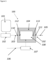
- the resistive heater 108 comprises a fluid input 112 and a fluid output 113 which are fluidically coupled, respectively, to the inlet 110 and the outlet 111.
- the fluid is supplied by the feed system 102 at a desired pressure and flow rate to the inflow 103.
- the source of electrical energy 106 is configured to supply a direct current, or an alternating current at any desired frequency, which heats the resistive heater 108.
- a single resistive heater 108 is located within the housing 104.
- a plurality of the resistive heaters 108 are located within the housing 104, and the resistive heaters 104 may be arranged in series or in parallel relative to the inflow 103 and outflow 105.
- the plurality of the resistive heaters 104 may be arranged electrically in series or in parallel.
- the electric heating system 100 is a resistojet and is configured for installation into a spacecraft, for use in moving the spacecraft in space.
- Figure 2 illustrates a first preferred embodiment of the present invention, in which the outlet 211 for the fluid outflow 205 has a converging shape defined by a frustoconical wall 201 of the housing 204.
- the outlet 211 expels the heated fluid through an orifice or orifices 202 at velocities less than or equal to the speed of sound in the fluid, retaining a high static temperature in the fluid.
- the degree of convergence of the frustoconical wall 201 may be varied, to change the outflow velocity and static temperature.
- Figure 3 illustrates a second preferred embodiment of the present invention, in which the outlet 311 for the fluid outflow 305 is integrated with the housing 304 or achieved with additional components.
- the outlet 311 is made with a converging section 301, a throat 302 and a diverging section 303.
- Such an outflow 305 when operating with back pressure within the housing sufficiently higher than the downstream or ambient pressure, expels the heated fluid at velocities greater than the speed of sound in the fluid. A cooler, high-velocity stream is thus produced.
- the degree of divergence of the duct may vary, to change the outflow velocity and static temperature.
- the outlet 211, 311 may be integral with a main body 220, 230 of the housing 204, 304 or may be comprised of additional components which are fitted to the main body 220, 230 of the housing 204, 304.
- additional components may increase the robustness of the electric heating system with respect to thermal stresses, permitting operation at higher temperatures for longer periods, as compared to the use of an integral housing including the outlet for the high temperature fluid outflow.
- the outlet for the fluid outflow may be straight, without any converging or diverging shape, with an orifice having a smaller diameter than the diameter of the main body of the housing.
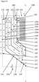
- resistive heater 108 in accordance with preferred embodiments of the present invention, which may be used in the arrangements of any of Figures 1 to 3 , is now described with reference to Figures 4 and 5 .
- the resistive heater 108 comprises a plurality of annular walls 120 composed of an electrically conductive material.
- annular means “generally ring-like", is not limited to geometrically circular shapes, and encompasses shapes that may be circular or other than circular, for example elliptical, polygonal, etc..
- the annular walls 120 have a circular cross-section.
- the annular walls may have any desired cross-sectional shape, which may be any polygonal shape, for example square, rectangular, triangular, hexagonal, etc., or may be a curved or rounded shape, for example circular, elliptical, etc..
- the annular walls 120 are nested to define a plurality of annular flow channels 122 which are serially arranged concentrically about a longitudinal axis L-L.
- the annular walls 120 extend between opposite first and second ends 124, 126 of the resistive heater 108 which are mutually separated along the longitudinal axis L-L.
- the plurality of annular walls 120 are mechanically connected together whereby adjacent flow channels 122 have opposite fluid flow directions and are connected at adjacent ends 128 of the respective channels 122 to define an alternating serpentine flow path 130 which has an input end 132 at the fluid input 112 and an output end 134 at the fluid output 113.
- the input and output ends 132, 134 are respectively located at radially outer and radially inner positions relative to the longitudinal axis L-L.
- the fluid input 112 and the fluid output 113 are respectively located at the first and second ends 124, 126 of the resistive heater 108.
- the alternating serpentine flow path 130 has first and second annular closed sides 131, 133 respectively located at the first and second ends 124, 126 of the resistive heater 108. At the closed sides 131, 133, turns 137, 139 are respectively provided connecting adjacent flow channels 122.
- the outermost wall 120f is cylindrical, and apart from the outermost wall 120f, each other wall 120a-120e inwardly thereof comprises a cylindrical portion 136 and an adjacent conical portion 138.
- a free end part 140 of the cylindrical portion 136 is located at the second end 126 of the resistive heater 108 and the conical portion 138 is oriented towards the first end 124 of the resistive heater 108.
- the conical portion 138 which is closest to the first end 124 of the resistive heater 108 comprises a solid layer 142 which defines a closed end part 144 of the plurality of annular walls 120.
- one annular wall 120e which is inwardly adjacent to outermost wall 120f, is configured to form the closed end part 144 of the plurality of annular walls 120 at the first end 124 of the resistive heater 108.
- the closed end part 144 closes the ends 128 of the annular flow channels 122 at the first end 124 of the resistive heater 108 to form directional changes in the alternating serpentine flow path 130 at the first end 124 of the resistive heater 108.
- Each annular wall 120 is composed of either a solid layer of the electrically conductive material, schematically illustrated by a solid line in Figure 5 , or a perforated layer of the electrically conductive material, schematically illustrated by a dashed line in Figure 5 .
- the resistive heater 108 comprises alternating annular walls 120 composed of a solid or perforated layer of the electrically conductive material.
- the innermost wall 120a is composed of a solid layer 125 of the electrically conductive material
- the adjacent wall 120b is composed of a perforated layer 127 of the electrically conductive material
- the next wall 120c is composed of a solid layer 125 of the electrically conductive material
- the next wall 120d is composed of a perforated layer 127 of the electrically conductive material
- the next wall 120e is composed of a solid layer 125 of the electrically conductive material
- the outermost wall 120f is composed of a perforated layer 127 of the electrically conductive material.
- each annular wall 120a, 120c, 120e composed of the solid layer 125 of the electrically conductive material has adjacent thereto, on at least one or both of a radially outer and a radially inner side thereof, an annular wall 120b, 120d, 120f composed of the perforated layer 127 of the electrically conductive material, and each annular wall 120b, 120d, 120f composed of the perforated layer 127 of the electrically conductive material has adjacent thereto, on at least one or both of a radially outer and a radially inner side thereof, an annular wall 120a, 120c, 120e composed of the solid layer 125 of the electrically conductive material.
- the perforated layer 127 comprises a perforated mesh, but may comprise any other types of perforation.
- each annular wall 120a-120f is composed of a solid layer 125 of the electrically conductive material.
- the annular walls 120a-120f comprise n walls which are nested to form a series of the annular walls 120a-120f.
- the series also has at least one radially intermediate wall 120b-120e between the radially innermost wall 120a and the radially outermost wall 120f.
- Each radially intermediate wall 120b-120e has a respective value of n between 1 and n.
- the solid annular walls 120a, 120c and 120e generate heat and create flow channels for the fluid.
- the struts 172 pass through the openings 168 provided in the annular walls 120, such that electric current passes from the electric terminal 150 through all perforated annular walls 120f, 120d and 120b in sequence, followed by the central heating coil 177, followed by all solid annular walls 120a, 120c and 120e in sequence to the electric terminal 152 (or vice versa).
- the terminal 150 comprises both an electric terminal (positive or negative) as well as the means of mechanically connecting the resistive heater 108 to the housing.
- the terminal 152 comprises an electric terminal (positive or negative) connected to an electric conductor passing through the wall of the housing 104, forming a pressure envelope boundary, and is sealed to the housing by an electrically insulating seal (not shown).
- the electric heating system 100 further comprises an annular closure member 188 which is located at the second end 126 of the resistive heater 108.
- the annular closure member 188 is shown highly schematically in Figure 5 , but for clarity of illustration is not shown in Figure 4 .
- the solid annular walls 120 define the flow channels 122 therebetween.
- the perforated annular walls 120 typically in the form of a perforated mesh, have an increased electrical resistance and an increased surface area as compared to a solid annular wall of the same dimensions. Consequently, the provision of alternating perforated annular walls 120 adjacent to the solid annular walls 120, and in particular within the flow channels 122, can achieve enhanced thermal transfer into the fluid for a given electrical current.
- the solid annular walls 120 have smooth inner and outer cylindrical surfaces.
- either or both of the inner and outer cylindrical surfaces may be provided with a relief surface, which may increase the surface area and may achieve enhanced heat transfer.
- Such surface features can readily be achieved using additive manufacturing processes, such as Selective Laser Melting (SLM).
- SLM Selective Laser Melting
- the annular walls 120 may also vary in thickness and cross-sectional shape and dimensions.
- the electrical heater system of the preferred embodiments of the present invention can provide a greater propellant usage efficiency (specific impulse - I sp ) as compared to any other current resistojet. Consequently, electrical heater system of the preferred embodiments of the present invention can provide a highly cost-effective propulsion system for small satellites, including constellations.
- the resistive heater in the electrical heater system of the preferred embodiments of the present invention can convert electrical energy to thermal energy, which is transferred to a fluid, with extreme efficiency.
- the resistive heater both releases energy directly to the flow and forms a recirculating path, which results in the highest temperature being generated in the centre of the resistive heater, achieving a thermal efficiency up to 95%.
- the resistive heater can heat a fluid to a temperatures as high as 3,500 K, without relying on combustion or any other chemical reaction.
- the resistive heater in the electrical heater system of the preferred embodiments of the present invention can be fabricated by an additive manufacturing process, for example Selective Laser Melting (SLM), to provide an integral monolithic resistive heater.
- SLM Selective Laser Melting
- This additive manufacturing process not only can be used as a single manufacturing process, which reduces cost and complexity during manufacturing, but also can provide a resistive heater which has high in-service reliability since thermal expansion stresses can be minimized or eliminated. This additive manufacturing process can also produce a compact, low cost of the monolithic resistive heater.
- the electrical heater system of the preferred embodiments of the present invention can be used to replace chemical propulsion systems that use hazardous propellants, which can significantly reduce the costs in satellite assembly integration and testing activities, and can simplify the design of the spacecraft.
- the electrical heater system of the preferred embodiments of the present invention can be used in a variety of other hot-flow applications, other than for satellite propulsion.
- the present invention may be of use for: as an electric generator of superheated steam for antimicrobial disinfection on biofilms and hard surfaces; food processing; epoxy resin curing; and stripping or cleaning purposes in refining and hydrocarbon industries; as an electric replacement for a gas torch for local heat-treatment; high-precision glass and jewellery working; pre-heating of equipment in the metal cast houses; and start-up heating of solid oxide fuel cells; the ignition of combustion engines; an electric heating source for hot gas welding of plastics and most metal alloys; a generator of highly energetic non-ionised flows in hypersonic wind tunnels, to test flight characteristics of aircraft, launchers and satellite re-entry; and a heat gun of enhanced temperature range, above a typical 600°C airflow temperature, for wire harness, soldering and de-soldering of circuit boards for electronics devices.
Landscapes
- Engineering & Computer Science (AREA)
- Chemical & Material Sciences (AREA)
- Combustion & Propulsion (AREA)
- Physics & Mathematics (AREA)
- Thermal Sciences (AREA)
- Mechanical Engineering (AREA)
- General Engineering & Computer Science (AREA)
- Remote Sensing (AREA)
- Aviation & Aerospace Engineering (AREA)
- Resistance Heating (AREA)
- Instantaneous Water Boilers, Portable Hot-Water Supply Apparatuses, And Control Of Portable Hot-Water Supply Apparatuses (AREA)
- Steam Or Hot-Water Central Heating Systems (AREA)
Claims (15)
- Ein elektrisches Heizsystem (100) zum Erhitzen eines Fluidstroms, wobei das System umfasst:ein Gehäuse (104; 204; 304) mit einem Einlass (110; 210; 310) für einen Fluidstrom, der durch das elektrische Heizsystem (100) erhitzt werden soll, und einem Auslass (111; 211; 311) für den Fluidstrom, der durch das elektrische Heizsystem (100) erhitzt wurde; undeinen Widerstandsheizer (108), der innerhalb des Gehäuses (104; 204; 304) montiert ist, wobei der Widerstandsheizer (108) umfasst:einen Fluideinlass (112) und einen Fluidauslass (113), die jeweils fluidisch mit dem Einlass (110; 210; 310) und dem Auslass (111; 211; 311) gekoppelt sind,eine Vielzahl von ringförmigen Wänden (120), die aus einem elektrisch leitfähigen Material bestehen, wobei die Wände (120) ineinander verschachtelt sind, um eine Vielzahl von ringförmigen Strömungskanälen (122) zu definieren, die seriell konzentrisch um eine Längsachse (L-L) angeordnet sind, wobei die Wände (120) sich zwischen gegenüberliegenden ersten und zweiten Enden (124, 126) des Widerstandsheizers (108) erstrecken, die entlang der Längsachse (L-L) voneinander getrennt sind, underste und zweite elektrische Anschlüsse (150, 152) zum Anschluss an eine Quelle elektrischer Energie, um die Wände (120) des Widerstandsheizers (108) zu erhitzen, wobei die ersten und zweiten elektrischen Anschlüsse (150, 152) elektrisch mit den jeweiligen ersten und zweiten Wänden (120f, 120e) verbunden sind,wobei die Vielzahl von ringförmigen Wänden (120) mechanisch miteinander verbunden sind, sodass benachbarte Strömungskanäle (122) entgegengesetzte Fluidströmungsrichtungen haben und an benachbarten Enden (128) der jeweiligen Kanäle (122) verbunden sind, um einen alternierenden serpentinenförmigen Strömungspfad (130) zu definieren, der ein Eingangsende (132) am Fluideinlass (112) und ein Ausgangsende (134) am Fluidauslass (113) hat, wobei die Eingangs- und Ausgangsenden (132, 134) jeweils an radial äußeren und radial inneren Positionen relativ zur Längsachse (L-L) angeordnet sind, undwobei die Vielzahl von ringförmigen Wänden (120) elektrisch miteinander verbunden sind, um einen kontinuierlichen elektrisch leitfähigen Pfad (156) zu definieren, der sich zwischen den ersten und zweiten elektrischen Anschlüssen (150, 152) erstreckt,dadurch gekennzeichnet, dass die ersten und zweiten Wände (120f, 120e) benachbart sind und ein äußeres Paar der Wände (120) umfassen, die sich an einer radial äußeren Seite des Widerstandsheizers (108) befinden, und der leitfähige Pfad (156) einen ersten Teil (158) hat, der sich von der ersten Wand (120f) zu einem Zentrum (C) des Widerstandsheizers (108) erstreckt, und einen zweiten Teil (160), der sich vom Zentrum (C) des Widerstandsheizers (108) zur zweiten Wand (120e) erstreckt.
- Das System nach Anspruch 1, wobei der Fluideinlass (112) und der Fluidauslass (113) jeweils an den ersten und zweiten Enden (124, 126) des Widerstandsheizers (108) angeordnet sind.
- Das System nach Anspruch 1 oder Anspruch 2, wobei (A) jede ringförmige Wand (120) entweder aus einer festen Schicht (125) des elektrisch leitfähigen Materials oder einer perforierten Schicht (127) des elektrisch leitfähigen Materials besteht, optional wobei der Widerstandsheizer (108) abwechselnde ringförmige Wände (120) umfasst, die aus einer festen oder perforierten Schicht (125, 127) des elektrisch leitfähigen Materials bestehen, wobei jede ringförmige Wand (120a, 120c, 120e), die aus der festen Schicht (125) des elektrisch leitfähigen Materials besteht, benachbart dazu, auf mindestens einer oder beiden radial äußeren und radial inneren Seiten davon, eine ringförmige Wand (120b, 120d, 120f) hat, die aus der perforierten Schicht (127) des elektrisch leitfähigen Materials besteht, und jede ringförmige Wand (120b, 120d, 120f), die aus der perforierten Schicht (127) des elektrisch leitfähigen Materials besteht, benachbart dazu, auf mindestens einer oder beiden radial äußeren und radial inneren Seiten davon, eine ringförmige Wand (120a, 120c, 120e) hat, die aus der festen Schicht (125) des elektrisch leitfähigen Materials besteht; oder (B) jede ringförmige Wand (120) besteht aus einer festen Schicht (125) des elektrisch leitfähigen Materials.
- Das System nach einem der Ansprüche 1 bis 3, wobei die Wände (120) n Wände (120) umfassen, die ineinander verschachtelt sind, um eine Serie der Wände (120) zu bilden, wobei die Serie eine radial innerste Wand (120a) hat, wobei n = 1, eine radial äußerste Wand (120f) hat, wobei n = n, und mindestens eine radial mittlere Wand (120b-120e) dazwischen, wobei jede eine jeweilige Wert von n zwischen 1 und n hat, wobei die Wände (120) elektrisch miteinander verbunden sind durch erste elektrische Verbindungen (162), die Wände (120) elektrisch verbinden, die n als gerade Zahl haben, um den ersten Teil (158) des leitfähigen Pfads (156) zu bilden, und durch zweite elektrische Verbindungen (164), die Wände (120) elektrisch verbinden, die n als ungerade Zahl haben, um den zweiten Teil (160) des leitfähigen Pfads (156) zu bilden, optional wobei die ersten und zweiten elektrischen Verbindungen (162, 164) integral mit den Wänden (120) sind, die durch die jeweilige elektrische Verbindung (162, 164) elektrisch miteinander verbunden sind, weiter optional wobei jede der ersten und zweiten elektrischen Verbindungen (162, 164) entweder parallel oder orthogonal zur Längsachse (L-L) ist.
- Das System nach Anspruch 4, wobei (i) mindestens einige Wände (120) mit Öffnungen (168) versehen sind, die sich durch diese erstrecken, und mindestens eine der ersten und zweiten elektrischen Verbindungen (162, 164) sich durch eine jeweilige Öffnung (168) erstreckt, und/oder (ii) die ersten und zweiten elektrischen Verbindungen (162, 164) auch mechanische Verbindungen (170) bereitstellen, durch die die Wände (120) mechanisch miteinander verbunden sind.
- Das System nach einem der Ansprüche 1 bis 5, wobei mindestens eine der Wände (120) einen zylindrischen Abschnitt (136) und einen angrenzenden konischen Abschnitt (138) umfasst, wobei ein freies Endteil (140) des zylindrischen Abschnitts (136) am zweiten Ende (126) des Widerstandsheizers (108) angeordnet ist und der konische Abschnitt (138) zum ersten Ende (124) des Widerstandsheizers (108) ausgerichtet ist, optional wobei der konische Abschnitt (138), der dem ersten Ende (124) des Widerstandsheizers (108) am nächsten ist, eine feste Schicht (142) umfasst, die ein geschlossenes Endteil (144) der Vielzahl von ringförmigen Wänden (120) definiert.
- Das System nach einem der Ansprüche 1 bis 6, wobei das elektrische Heizsystem (100) weiter ein ringförmiges Verschlusselement (188) umfasst, das aus einem elektrisch isolierenden Material besteht und am zweiten Ende (126) des Widerstandsheizers (108) angeordnet ist, wobei das Verschlusselement (188) die Enden der ringförmigen Strömungskanäle (122) am zweiten Ende (126) des Widerstandsheizers (108) verschließt, um Richtungsänderungen im alternierenden serpentinenförmigen Strömungspfad (130) am zweiten Ende (126) des Widerstandsheizers (108) zu bilden, optional wobei das mindestens eine elektrisch isolierende Verschlusselement (188) in Kontakt mit oder entfernt vom Widerstandsheizer (108) ist.
- Das System nach einem der Ansprüche 1 bis 7, wobei eine ringförmige Wand (120e) konfiguriert ist, um ein geschlossenes Endteil (144) der Vielzahl von ringförmigen Wänden (120) am ersten Ende (124) des Widerstandsheizers (108) zu bilden, wobei das geschlossene Endteil (144) die Enden (128) der ringförmigen Strömungskanäle (122) am ersten Ende (124) des Widerstandsheizers (108) verschließt, um Richtungsänderungen im alternierenden serpentinenförmigen Strömungspfad (130) am ersten Ende (124) des Widerstandsheizers (108) zu bilden.
- Das System nach einem der Ansprüche 1 bis 8, wobei der Widerstandsheizer (108) weiter einen elektrischen Verbinder (176) umfasst, der aus einem elektrisch leitfähigen Material besteht und am Zentrum (C) des Widerstandsheizers (108) angeordnet ist, der ein inneres Paar der ringförmigen Wände (120a, 120b) elektrisch miteinander verbindet, optional wobei der elektrische Verbinder (176) ein Paar von länglichen spiralförmigen Elementen (178a, 178b) umfasst, die konzentrisch um die Längsachse (L-L) angeordnet sind und von der innersten Wand (120a) umgeben sind, wobei ein erstes Ende (180a, 180b) jedes spiralförmigen Elements (178a, 178b) mit einer jeweiligen Wand (120a, 120b) des inneren Paares der Wände (120a, 120b) verbunden ist und gegenüberliegende zweite Enden (182a, 192b) der spiralförmigen Elemente (178a, 178b) durch ein Verbindungselement (184) des elektrischen Verbinders (176) miteinander verbunden sind, weiter optional wobei (i) das Verbindungselement (184) einen ringförmigen Ring umfasst und/oder (ii) die ersten Enden (180a, 180b) der spiralförmigen Elemente (178a, 178b) am zweiten Ende (126) des Widerstandsheizers (108) angeordnet sind.
- Das System nach einem der Ansprüche 1 bis 9, wobei der Widerstandsheizer (108) einen integralen monolithischen Körper (186) umfasst, optional wobei der integrale monolithische Körper (186) durch eine additive Fertigungstechnik hergestellt wird, optional ausgewählt aus Selektivem Laserschmelzen (SLM), Selektivem Lasersintern (SLS), Direktmetall-Lasersintern (DMLS), Neutralstrahlschmelzen (NBM), Elektronenstrahlschweißen (EBW), Laserdepositionsschweißen (LDW), Laserstrahlschmelzen (LBM), Lasermetallabscheidung (LMD), Elektronenstrahlschmelzen (EBM), Direkter Energieabscheidung (DED), Rapid Prototyping (RP) oder Rapid Manufacturing (RM).
- Das System nach einem der Ansprüche 1 bis 10, wobei (A) das Gehäuse (104) elektrisch mit einem der ersten und zweiten elektrischen Anschlüsse (150, 152) des Widerstandsheizers (108) verbunden ist, wodurch der jeweilige elektrische Anschluss (150, 152) über das Gehäuse (104) mit der Quelle elektrischer Energie (106) verbunden werden kann, optional wobei der jeweilige elektrische Anschluss (150, 152) integral mit oder getrennt von einer mechanischen Verbindung zwischen dem Widerstandsheizer (108) und dem Gehäuse (104) ist; und/oder (B) die ersten und zweiten elektrischen Anschlüsse (150, 152) konfiguriert sind, um durch eine kabelgebundene Verbindung mit der Quelle elektrischer Energie (106) verbunden zu werden, und das System weiter eine Quelle elektrischer Energie (106) umfasst, die mit den ersten und zweiten elektrischen Anschlüssen (150, 152) verbunden ist, wobei die Quelle elektrischer Energie (106) konfiguriert ist, Gleichstrom oder Wechselstrom zu liefern.
- Das System nach einem der Ansprüche 1 bis 11, wobei eine Vielzahl der Widerstandsheizer (108) innerhalb des Gehäuses (104) angeordnet sind und die Widerstandsheizer (108) relativ zum Einlass (110; 210; 310) und Auslass (111; 211; 311) für den Fluidstrom in Serie oder parallel angeordnet sind.
- Das System nach einem der Ansprüche 1 bis 12, wobei das elektrische Heizsystem (100) ein Resistojet ist und für die Installation in ein Raumfahrzeug konfiguriert ist, um das Raumfahrzeug im Weltraum zu bewegen.
- Ein Verfahren zur Erzeugung eines Hochtemperatur-Fluidstroms, wobei das Verfahren die folgenden Schritte umfasst:a) Bereitstellen eines elektrischen Heizsystems (100) gemäß einem der Ansprüche 1 bis 13;b) Zuführen eines zu erhitzenden Fluids zum Fluideinlass (112) des Widerstandsheizers (108) und dadurch entlang des alternierenden serpentinenförmigen Strömungspfads (130) zum Fluidauslass (113) des Widerstandsheizers (108) strömen lassen, wobei das zugeführte Fluid einen höheren Druck als der äußere Gasdruck um das Äußere (192) des Gehäuses (104) hat;c) Anlegen eines elektrischen Potentials an die ersten und zweiten Anschlüsse (150, 152), um den Fluidstrom im alternierenden serpentinenförmigen Strömungspfad (130) durch den Widerstandsheizer (108) zu erhitzen; undd) Ausstoßen des erhitzten Fluidstroms aus dem Auslass (111; 211; 311) des Gehäuses (104).
- Das Verfahren nach Anspruch 14, wobei (i) das erhitzte Fluid aus dem Auslass (111; 211; 311) des Gehäuses (104) mit einer Unterschall- oder Schallgeschwindigkeit über eine konvergierende Düse ausgestoßen wird, oder (ii) das erhitzte Fluid aus dem Auslass (111; 211; 311) des Gehäuses (104) mit einer Überschall- oder Hyperschallgeschwindigkeit über eine konvergierende-divergierende Düse ausgestoßen wird.
Applications Claiming Priority (2)
| Application Number | Priority Date | Filing Date | Title |
|---|---|---|---|
| GB2018469.3A GB2601309A (en) | 2020-11-24 | 2020-11-24 | Electric heating system for heating a fluid flow |
| PCT/EP2021/080614 WO2022111968A2 (en) | 2020-11-24 | 2021-11-04 | Electric heating system for heating a fluid flow |
Publications (2)
| Publication Number | Publication Date |
|---|---|
| EP4233490A2 EP4233490A2 (de) | 2023-08-30 |
| EP4233490B1 true EP4233490B1 (de) | 2025-07-02 |
Family
ID=74046921
Family Applications (1)
| Application Number | Title | Priority Date | Filing Date |
|---|---|---|---|
| EP21807010.0A Active EP4233490B1 (de) | 2020-11-24 | 2021-11-04 | Elektrisches heizsystem zum erwärmen eines fluidstroms |
Country Status (11)
| Country | Link |
|---|---|
| US (1) | US20230417451A1 (de) |
| EP (1) | EP4233490B1 (de) |
| JP (1) | JP7825291B2 (de) |
| CN (1) | CN116670445A (de) |
| AU (1) | AU2021390034A1 (de) |
| CA (1) | CA3199450A1 (de) |
| ES (1) | ES3038284T3 (de) |
| GB (1) | GB2601309A (de) |
| HU (1) | HUE073239T2 (de) |
| PL (1) | PL4233490T3 (de) |
| WO (1) | WO2022111968A2 (de) |
Families Citing this family (1)
| Publication number | Priority date | Publication date | Assignee | Title |
|---|---|---|---|---|
| US12330816B1 (en) * | 2024-05-20 | 2025-06-17 | Robert Alan Hickman | Advanced electric resistance thermal propulsion systems |
Family Cites Families (11)
| Publication number | Priority date | Publication date | Assignee | Title |
|---|---|---|---|---|
| GB992916A (en) * | 1962-04-26 | 1965-05-26 | Parsons C A & Co Ltd | Improvements in and relating to electric heaters for gases |
| JPS6264700A (ja) * | 1985-09-17 | 1987-03-23 | 三菱電機株式会社 | スラスタ |
| US4855571A (en) * | 1988-01-29 | 1989-08-08 | Industrial Technology Research Institute | Positive temperature coefficient ceramic heating element for heating a fluid |
| JPH0361172U (de) * | 1989-10-17 | 1991-06-14 | ||
| BR112013017413A2 (pt) * | 2011-01-07 | 2016-09-27 | Microheat Technologies Pty Ltd | aquecedor de fluido elétrico e mpetodo de eletricamente aquecer fluido |
| US8562359B2 (en) * | 2011-01-18 | 2013-10-22 | Tyco Electronics Corporation | Electrical contact for interconnect member |
| JP2018116803A (ja) * | 2017-01-17 | 2018-07-26 | 国立研究開発法人宇宙航空研究開発機構 | 電熱ヒータ、噴射装置及び宇宙機 |
| US11077964B1 (en) | 2017-05-12 | 2021-08-03 | H.C. Starck Inc. | High-temperature electrothermal propulsion system |
| US20190145658A1 (en) * | 2017-11-16 | 2019-05-16 | Akurate Dynamics, Llc | In-line electric heater for plural component materials |
| CN208144423U (zh) * | 2018-02-26 | 2018-11-27 | 常州市派腾电子技术服务有限公司 | 烤烟加热件、烟锅装置及电子烟 |
| CN110173888A (zh) * | 2019-05-10 | 2019-08-27 | 佛山建邦机械有限公司 | 一种套管式空气电加热器 |
-
2020
- 2020-11-24 GB GB2018469.3A patent/GB2601309A/en not_active Withdrawn
-
2021
- 2021-11-04 ES ES21807010T patent/ES3038284T3/es active Active
- 2021-11-04 JP JP2023531081A patent/JP7825291B2/ja active Active
- 2021-11-04 WO PCT/EP2021/080614 patent/WO2022111968A2/en not_active Ceased
- 2021-11-04 AU AU2021390034A patent/AU2021390034A1/en active Pending
- 2021-11-04 US US18/038,075 patent/US20230417451A1/en active Pending
- 2021-11-04 CA CA3199450A patent/CA3199450A1/en active Pending
- 2021-11-04 CN CN202180087248.4A patent/CN116670445A/zh active Pending
- 2021-11-04 EP EP21807010.0A patent/EP4233490B1/de active Active
- 2021-11-04 PL PL21807010.0T patent/PL4233490T3/pl unknown
- 2021-11-04 HU HUE21807010A patent/HUE073239T2/hu unknown
Also Published As
| Publication number | Publication date |
|---|---|
| AU2021390034A1 (en) | 2023-06-22 |
| GB202018469D0 (en) | 2021-01-06 |
| EP4233490A2 (de) | 2023-08-30 |
| PL4233490T3 (pl) | 2025-11-03 |
| JP2023550513A (ja) | 2023-12-01 |
| CN116670445A (zh) | 2023-08-29 |
| CA3199450A1 (en) | 2022-06-02 |
| US20230417451A1 (en) | 2023-12-28 |
| WO2022111968A3 (en) | 2022-08-11 |
| WO2022111968A2 (en) | 2022-06-02 |
| ES3038284T3 (en) | 2025-10-10 |
| GB2601309A (en) | 2022-06-01 |
| HUE073239T2 (hu) | 2026-01-28 |
| JP7825291B2 (ja) | 2026-03-06 |
Similar Documents
| Publication | Publication Date | Title |
|---|---|---|
| US7997510B2 (en) | Systems, methods and apparatus for propulsion | |
| JP6200994B2 (ja) | 熱結合した燃料マニホールド | |
| US4825647A (en) | Performance improvements in thruster assembly | |
| US6523350B1 (en) | Fuel injector fuel conduits with multiple laminated fuel strips | |
| US2458497A (en) | Combustion chamber | |
| US12129814B2 (en) | Thrust vector control for hybrid propellants rocket engine with embedded fluid injection ports | |
| EP4233490B1 (de) | Elektrisches heizsystem zum erwärmen eines fluidstroms | |
| JP2016180580A (ja) | クロスフロー導管熱交換器内の管 | |
| JP2007024045A (ja) | 熱電生成を伴うエンジン熱交換器 | |
| US7665292B2 (en) | Thruster with electro-thermal thrust augmentation | |
| EP3129709B1 (de) | Brennkammer einer triebflüssigkeitmotor | |
| Kilcoin et al. | Development of ASCENT propellant thrusters and propulsion systems | |
| EP1352166B1 (de) | Abgabedüse und verfahren zur herstellung einer abgabedüse | |
| JP2018116803A (ja) | 電熱ヒータ、噴射装置及び宇宙機 | |
| WO2023205122A1 (en) | Integrated heaters having nonlinear passageways for heating fluids, and apparatuses incorporating same | |
| JP7425895B2 (ja) | スラスタ組立体 | |
| JP2008255786A (ja) | 推力装置 | |
| RU2834321C1 (ru) | Электротермический узел парового двигателя для наноспутников | |
| Miotti et al. | Bi-propellant micro-rocket engine | |
| KR102928649B1 (ko) | 재점화기를 포함하는 액체로켓엔진 | |
| WO2025199586A1 (en) | A thruster | |
| RU2728657C1 (ru) | Камера жидкостного ракетного двигателя, работающего по безгазогенераторной схеме (варианты) | |
| Blinov et al. | The research of ammonia electrothermal microengines for small spacecrafts | |
| US20210363897A1 (en) | Thermal insulation features for gas turbine engines | |
| Miyake et al. | Performance characterization tests of a 1-kW resistojet using hydrogen, nitrogen and ammonia as propellants |
Legal Events
| Date | Code | Title | Description |
|---|---|---|---|
| STAA | Information on the status of an ep patent application or granted ep patent |
Free format text: STATUS: UNKNOWN |
|
| STAA | Information on the status of an ep patent application or granted ep patent |
Free format text: STATUS: THE INTERNATIONAL PUBLICATION HAS BEEN MADE |
|
| PUAI | Public reference made under article 153(3) epc to a published international application that has entered the european phase |
Free format text: ORIGINAL CODE: 0009012 |
|
| STAA | Information on the status of an ep patent application or granted ep patent |
Free format text: STATUS: REQUEST FOR EXAMINATION WAS MADE |
|
| 17P | Request for examination filed |
Effective date: 20230524 |
|
| AK | Designated contracting states |
Kind code of ref document: A2 Designated state(s): AL AT BE BG CH CY CZ DE DK EE ES FI FR GB GR HR HU IE IS IT LI LT LU LV MC MK MT NL NO PL PT RO RS SE SI SK SM TR |
|
| DAV | Request for validation of the european patent (deleted) | ||
| DAX | Request for extension of the european patent (deleted) | ||
| GRAP | Despatch of communication of intention to grant a patent |
Free format text: ORIGINAL CODE: EPIDOSNIGR1 |
|
| STAA | Information on the status of an ep patent application or granted ep patent |
Free format text: STATUS: GRANT OF PATENT IS INTENDED |
|
| RIC1 | Information provided on ipc code assigned before grant |
Ipc: F24H 9/00 20220101ALI20250114BHEP Ipc: H05B 3/44 20060101ALI20250114BHEP Ipc: H05B 3/06 20060101ALI20250114BHEP Ipc: F24H 9/1863 20220101ALI20250114BHEP Ipc: F24H 3/04 20220101ALI20250114BHEP Ipc: H05B 3/78 20060101AFI20250114BHEP |
|
| INTG | Intention to grant announced |
Effective date: 20250127 |
|
| GRAS | Grant fee paid |
Free format text: ORIGINAL CODE: EPIDOSNIGR3 |
|
| GRAA | (expected) grant |
Free format text: ORIGINAL CODE: 0009210 |
|
| STAA | Information on the status of an ep patent application or granted ep patent |
Free format text: STATUS: THE PATENT HAS BEEN GRANTED |
|
| AK | Designated contracting states |
Kind code of ref document: B1 Designated state(s): AL AT BE BG CH CY CZ DE DK EE ES FI FR GB GR HR HU IE IS IT LI LT LU LV MC MK MT NL NO PL PT RO RS SE SI SK SM TR |
|
| REG | Reference to a national code |
Ref country code: GB Ref legal event code: FG4D |
|
| REG | Reference to a national code |
Ref country code: CH Ref legal event code: EP |
|
| REG | Reference to a national code |
Ref country code: DE Ref legal event code: R096 Ref document number: 602021033486 Country of ref document: DE |
|
| REG | Reference to a national code |
Ref country code: IE Ref legal event code: FG4D |
|
| REG | Reference to a national code |
Ref country code: ES Ref legal event code: FG2A Ref document number: 3038284 Country of ref document: ES Kind code of ref document: T3 Effective date: 20251010 |
|
| REG | Reference to a national code |
Ref country code: NL Ref legal event code: MP Effective date: 20250702 |
|
| REG | Reference to a national code |
Ref country code: SK Ref legal event code: T3 Ref document number: E 47201 Country of ref document: SK |
|
| REG | Reference to a national code |
Ref country code: CH Ref legal event code: U11 Free format text: ST27 STATUS EVENT CODE: U-0-0-U10-U11 (AS PROVIDED BY THE NATIONAL OFFICE) Effective date: 20251201 |
|
| PG25 | Lapsed in a contracting state [announced via postgrant information from national office to epo] |
Ref country code: PT Free format text: LAPSE BECAUSE OF FAILURE TO SUBMIT A TRANSLATION OF THE DESCRIPTION OR TO PAY THE FEE WITHIN THE PRESCRIBED TIME-LIMIT Effective date: 20251103 |
|
| PGFP | Annual fee paid to national office [announced via postgrant information from national office to epo] |
Ref country code: HU Payment date: 20251125 Year of fee payment: 5 |
|
| PG25 | Lapsed in a contracting state [announced via postgrant information from national office to epo] |
Ref country code: NL Free format text: LAPSE BECAUSE OF FAILURE TO SUBMIT A TRANSLATION OF THE DESCRIPTION OR TO PAY THE FEE WITHIN THE PRESCRIBED TIME-LIMIT Effective date: 20250702 |
|
| PGFP | Annual fee paid to national office [announced via postgrant information from national office to epo] |
Ref country code: LU Payment date: 20251119 Year of fee payment: 5 |
|
| REG | Reference to a national code |
Ref country code: EE Ref legal event code: FG4A Ref document number: E025448 Country of ref document: EE Effective date: 20251124 Ref country code: AT Ref legal event code: MK05 Ref document number: 1810805 Country of ref document: AT Kind code of ref document: T Effective date: 20250702 |
|
| REG | Reference to a national code |
Ref country code: NL Ref legal event code: NE Effective date: 20251222 |
|
| PG25 | Lapsed in a contracting state [announced via postgrant information from national office to epo] |
Ref country code: IS Free format text: LAPSE BECAUSE OF FAILURE TO SUBMIT A TRANSLATION OF THE DESCRIPTION OR TO PAY THE FEE WITHIN THE PRESCRIBED TIME-LIMIT Effective date: 20251102 |
|
| PGFP | Annual fee paid to national office [announced via postgrant information from national office to epo] |
Ref country code: DE Payment date: 20251119 Year of fee payment: 5 |
|
| PGFP | Annual fee paid to national office [announced via postgrant information from national office to epo] |
Ref country code: GB Payment date: 20251121 Year of fee payment: 5 |
|
| PGFP | Annual fee paid to national office [announced via postgrant information from national office to epo] |
Ref country code: NO Payment date: 20251125 Year of fee payment: 5 |
|
| REG | Reference to a national code |
Ref country code: LT Ref legal event code: MG9D |
|
| PG25 | Lapsed in a contracting state [announced via postgrant information from national office to epo] |
Ref country code: AT Free format text: LAPSE BECAUSE OF FAILURE TO SUBMIT A TRANSLATION OF THE DESCRIPTION OR TO PAY THE FEE WITHIN THE PRESCRIBED TIME-LIMIT Effective date: 20250702 |
|
| PGFP | Annual fee paid to national office [announced via postgrant information from national office to epo] |
Ref country code: FI Payment date: 20251231 Year of fee payment: 5 |
|
| PG25 | Lapsed in a contracting state [announced via postgrant information from national office to epo] |
Ref country code: HR Free format text: LAPSE BECAUSE OF FAILURE TO SUBMIT A TRANSLATION OF THE DESCRIPTION OR TO PAY THE FEE WITHIN THE PRESCRIBED TIME-LIMIT Effective date: 20250702 |
|
| PGFP | Annual fee paid to national office [announced via postgrant information from national office to epo] |
Ref country code: FR Payment date: 20251126 Year of fee payment: 5 |
|
| PG25 | Lapsed in a contracting state [announced via postgrant information from national office to epo] |
Ref country code: GR Free format text: LAPSE BECAUSE OF FAILURE TO SUBMIT A TRANSLATION OF THE DESCRIPTION OR TO PAY THE FEE WITHIN THE PRESCRIBED TIME-LIMIT Effective date: 20251003 |
|
| PGFP | Annual fee paid to national office [announced via postgrant information from national office to epo] |
Ref country code: BE Payment date: 20251119 Year of fee payment: 5 |
|
| PGFP | Annual fee paid to national office [announced via postgrant information from national office to epo] |
Ref country code: CH Payment date: 20251201 Year of fee payment: 5 |
|
| PG25 | Lapsed in a contracting state [announced via postgrant information from national office to epo] |
Ref country code: SE Free format text: LAPSE BECAUSE OF FAILURE TO SUBMIT A TRANSLATION OF THE DESCRIPTION OR TO PAY THE FEE WITHIN THE PRESCRIBED TIME-LIMIT Effective date: 20250702 |
|
| PGFP | Annual fee paid to national office [announced via postgrant information from national office to epo] |
Ref country code: IE Payment date: 20251121 Year of fee payment: 5 Ref country code: CZ Payment date: 20251029 Year of fee payment: 5 |
|
| PG25 | Lapsed in a contracting state [announced via postgrant information from national office to epo] |
Ref country code: LV Free format text: LAPSE BECAUSE OF FAILURE TO SUBMIT A TRANSLATION OF THE DESCRIPTION OR TO PAY THE FEE WITHIN THE PRESCRIBED TIME-LIMIT Effective date: 20250702 |
|
| PG25 | Lapsed in a contracting state [announced via postgrant information from national office to epo] |
Ref country code: BG Free format text: LAPSE BECAUSE OF FAILURE TO SUBMIT A TRANSLATION OF THE DESCRIPTION OR TO PAY THE FEE WITHIN THE PRESCRIBED TIME-LIMIT Effective date: 20250702 |
|
| PGFP | Annual fee paid to national office [announced via postgrant information from national office to epo] |
Ref country code: PL Payment date: 20251024 Year of fee payment: 5 |
|
| PGFP | Annual fee paid to national office [announced via postgrant information from national office to epo] |
Ref country code: SK Payment date: 20251030 Year of fee payment: 5 |
|
| PG25 | Lapsed in a contracting state [announced via postgrant information from national office to epo] |
Ref country code: RS Free format text: LAPSE BECAUSE OF FAILURE TO SUBMIT A TRANSLATION OF THE DESCRIPTION OR TO PAY THE FEE WITHIN THE PRESCRIBED TIME-LIMIT Effective date: 20251002 |
|
| REG | Reference to a national code |
Ref country code: HU Ref legal event code: AG4A Ref document number: E073239 Country of ref document: HU |
|
| PGFP | Annual fee paid to national office [announced via postgrant information from national office to epo] |
Ref country code: ES Payment date: 20251229 Year of fee payment: 5 |
|
| PG25 | Lapsed in a contracting state [announced via postgrant information from national office to epo] |
Ref country code: SM Free format text: LAPSE BECAUSE OF FAILURE TO SUBMIT A TRANSLATION OF THE DESCRIPTION OR TO PAY THE FEE WITHIN THE PRESCRIBED TIME-LIMIT Effective date: 20250702 |
|
| PGFP | Annual fee paid to national office [announced via postgrant information from national office to epo] |
Ref country code: SE Payment date: 20251222 Year of fee payment: 5 |
|
| PG25 | Lapsed in a contracting state [announced via postgrant information from national office to epo] |
Ref country code: DK Free format text: LAPSE BECAUSE OF FAILURE TO SUBMIT A TRANSLATION OF THE DESCRIPTION OR TO PAY THE FEE WITHIN THE PRESCRIBED TIME-LIMIT Effective date: 20250702 |