EP4233338B1 - Dynamische ue-signalpegelkorrektur für messmodifikation und/oder stationaritätserkennung - Google Patents
Dynamische ue-signalpegelkorrektur für messmodifikation und/oder stationaritätserkennung Download PDFInfo
- Publication number
- EP4233338B1 EP4233338B1 EP20958872.2A EP20958872A EP4233338B1 EP 4233338 B1 EP4233338 B1 EP 4233338B1 EP 20958872 A EP20958872 A EP 20958872A EP 4233338 B1 EP4233338 B1 EP 4233338B1
- Authority
- EP
- European Patent Office
- Prior art keywords
- user equipment
- parameters
- variation
- measurement
- measurement modification
- Prior art date
- Legal status (The legal status is an assumption and is not a legal conclusion. Google has not performed a legal analysis and makes no representation as to the accuracy of the status listed.)
- Active
Links
Images


Classifications
-
- H—ELECTRICITY
- H04—ELECTRIC COMMUNICATION TECHNIQUE
- H04W—WIRELESS COMMUNICATION NETWORKS
- H04W24/00—Supervisory, monitoring or testing arrangements
- H04W24/08—Testing, supervising or monitoring using real traffic
-
- H—ELECTRICITY
- H04—ELECTRIC COMMUNICATION TECHNIQUE
- H04B—TRANSMISSION
- H04B17/00—Monitoring; Testing
- H04B17/30—Monitoring; Testing of propagation channels
- H04B17/309—Measuring or estimating channel quality parameters
- H04B17/318—Received signal strength
- H04B17/328—Reference signal received power [RSRP]; Reference signal received quality [RSRQ]
-
- H—ELECTRICITY
- H04—ELECTRIC COMMUNICATION TECHNIQUE
- H04W—WIRELESS COMMUNICATION NETWORKS
- H04W24/00—Supervisory, monitoring or testing arrangements
- H04W24/10—Scheduling measurement reports ; Arrangements for measurement reports
-
- H—ELECTRICITY
- H04—ELECTRIC COMMUNICATION TECHNIQUE
- H04W—WIRELESS COMMUNICATION NETWORKS
- H04W48/00—Access restriction; Network selection; Access point selection
- H04W48/20—Selecting an access point
-
- H—ELECTRICITY
- H04—ELECTRIC COMMUNICATION TECHNIQUE
- H04W—WIRELESS COMMUNICATION NETWORKS
- H04W52/00—Power management, e.g. Transmission Power Control [TPC] or power classes
- H04W52/02—Power saving arrangements
- H04W52/0209—Power saving arrangements in terminal devices
- H04W52/0212—Power saving arrangements in terminal devices managed by the network, e.g. network or access point is leader and terminal is follower
-
- H—ELECTRICITY
- H04—ELECTRIC COMMUNICATION TECHNIQUE
- H04W—WIRELESS COMMUNICATION NETWORKS
- H04W52/00—Power management, e.g. Transmission Power Control [TPC] or power classes
- H04W52/02—Power saving arrangements
- H04W52/0209—Power saving arrangements in terminal devices
- H04W52/0251—Power saving arrangements in terminal devices using monitoring of local events, e.g. events related to user activity
-
- Y—GENERAL TAGGING OF NEW TECHNOLOGICAL DEVELOPMENTS; GENERAL TAGGING OF CROSS-SECTIONAL TECHNOLOGIES SPANNING OVER SEVERAL SECTIONS OF THE IPC; TECHNICAL SUBJECTS COVERED BY FORMER USPC CROSS-REFERENCE ART COLLECTIONS [XRACs] AND DIGESTS
- Y02—TECHNOLOGIES OR APPLICATIONS FOR MITIGATION OR ADAPTATION AGAINST CLIMATE CHANGE
- Y02D—CLIMATE CHANGE MITIGATION TECHNOLOGIES IN INFORMATION AND COMMUNICATION TECHNOLOGIES [ICT], I.E. INFORMATION AND COMMUNICATION TECHNOLOGIES AIMING AT THE REDUCTION OF THEIR OWN ENERGY USE
- Y02D30/00—Reducing energy consumption in communication networks
- Y02D30/70—Reducing energy consumption in communication networks in wireless communication networks
Definitions
- Exemplary embodiments herein relate generally to wireless networks and, more specifically, relates to determining whether user equipment (UEs) need measurement modifications, e.g., for radio resource management (RRM) modifications and/or are stationary in the networks.
- UEs user equipment
- RRM radio resource management
- RedCap reduced capability
- the study item (RP-193238) has the following objective:
- One issue with these reduced capability UEs is determining stationarity of the devices.
- EP2092666 describes methods for performing measurements in different periods by a user equipment being in a discontinuous reception mode. These periods have different frequency and dependent on measured signal strengths.
- US 2016/234747 describes cell measurements which are periodic or trigger event based. The measurements may be suspended based on signal quality and cell changes.
- EP3110200 describes methods for performing measurements by mobile terminal devices. These measurements are scheduled based on repetition periods.
- the exemplary embodiments herein describe techniques for dynamic UE signal level correction for stationarity detection. Additional description of these techniques is presented after a system into which the exemplary embodiments may be used is described.
- FIG. 1 this figure shows a block diagram of one possible and non-limiting exemplary system in which the exemplary embodiments may be practiced.
- a user equipment (UE) 110 radio access network (RAN) node 170, and network element(s) 190 are illustrated.
- a user equipment (UE) 110 is in wireless communication with a wireless network 100.
- a UE is a wireless, typically mobile device that can access a wireless network.
- the UE 110 includes one or more processors 120, one or more memories 125, and one or more transceivers 130 interconnected through one or more buses 127. Each of the one or more transceivers 130 includes a receiver, Rx, 132 and a transmitter, Tx, 133.
- the one or more buses 127 may be address, data, or control buses, and may include any interconnection mechanism, such as a series of lines on a motherboard or integrated circuit, fiber optics or other optical communication equipment, and the like.
- the one or more transceivers 130 are connected to one or more antennas 128.
- the one or more memories 125 include computer program code 123.
- the UE 110 includes a control module 140, comprising one of or both parts 140-1 and/or 140-2, which may be implemented in a number of ways.
- the control module 140 may be implemented in hardware as control module 140-1, such as being implemented as part of the one or more processors 120.
- the control module 140-1 may be implemented also as an integrated circuit or through other hardware such as a programmable gate array.
- control module 140 may be implemented as control module 140-2, which is implemented as computer program code 123 and is executed by the one or more processors 120.
- the one or more memories 125 and the computer program code 123 may be configured to, with the one or more processors 120, cause the user equipment 110 to perform one or more of the operations as described herein.
- the UE 110 communicates with RAN node 170 via a wireless link 111.
- the RAN node 170 is a base station that provides access by wireless devices such as the UE 110 to the wireless network 100.
- the term "base station” (or BS) is also used for the RAN node 170.
- the RAN node 170 may be, for instance, a base station for 5G, also called New Radio (NR).
- the RAN node 170 may be a NG-RAN node, which is defined as either a gNB or an ng-eNB.
- a gNB is a node providing NR user plane and control plane protocol terminations towards the UE, and connected via the NG interface to a 5GC (e.g., the network element(s) 190).
- the ng-eNB is a node providing E-UTRA user plane and control plane protocol terminations towards the UE, and connected via the NG interface to the 5GC.
- the NG-RAN node may include multiple gNBs, which may also include a central unit (CU) (gNB-CU) 196 and distributed unit(s) (DUs) (gNB-DUs), of which DU 195 is shown.
- the DU may include or be coupled to and control a radio unit (RU).
- the gNB-CU is a logical node hosting RRC, SDAP and PDCP protocols of the gNB or RRC and PDCP protocols of the en-gNB that controls the operation of one or more gNB-DUs.
- the gNB-CU terminates the F1 interface connected with the gNB-DU.
- the F1 interface is illustrated as reference 198, although reference 198 also illustrates a link between remote elements of the RAN node 170 and centralized elements of the RAN node 170, such as between the gNB-CU 196 and the gNB-DU 195.
- the gNB-DU is a logical node hosting RLC, MAC and PHY layers of the gNB or en-gNB, and its operation is partly controlled by gNB-CU.
- One gNB-CU supports one or multiple cells.
- One cell is supported by one gNB-DU.
- the gNB-DU terminates the F1 interface 198 connected with the gNB-CU.
- the DU 195 is considered to include the transceiver 160, e.g., as part of an RU, but some examples of this may have the transceiver 160 as part of a separate RU, e.g., under control of and connected to the DU 195.
- the RAN node 170 may also be an eNB (evolved NodeB) base station, for LTE (long term evolution), or any other suitable base station.
- eNB evolved NodeB
- the RAN node 170 includes one or more processors 152, one or more memories 155, one or more network interfaces (N/W I/F(s)) 161, and one or more transceivers 160 interconnected through one or more buses 157.
- Each of the one or more transceivers 160 includes a receiver, Rx, 162 and a transmitter, Tx, 163.
- the one or more transceivers 160 are connected to one or more antennas 158.
- the one or more memories 155 include computer program code 153.
- the CU 196 may include the processor(s) 152, memories 155, and network interfaces 161. Note that the DU 195 may also contain its own memory/memories and processor(s), and/or other hardware, but these are not shown.
- the RAN node 170 includes a control module 150, comprising one of or both parts 150-1 and/or 150-2, which may be implemented in a number of ways.
- the control module 150 may be implemented in hardware as control module 150-1, such as being implemented as part of the one or more processors 152.
- the control module 150-1 may be implemented also as an integrated circuit or through other hardware such as a programmable gate array.
- the control module 150 may be implemented as control module 150-2, which is implemented as computer program code 153 and is executed by the one or more processors 152.
- the one or more memories 155 and the computer program code 153 are configured to, with the one or more processors 152, cause the RAN node 170 to perform one or more of the operations as described herein.
- the functionality of the control module 150 may be distributed, such as being distributed between the DU 195 and the CU 196, or be implemented solely in the DU 195.
- the one or more network interfaces 161 communicate over a network such as via the links 176 and 131.
- Two or more RAN nodes 170 communicate using, e.g., link 176.
- the link 176 may be wired or wireless or both and may implement, e.g., an Xn interface for 5G, an X2 interface for LTE, or other suitable interface for other standards.
- the one or more buses 157 may be address, data, or control buses, and may include any interconnection mechanism, such as a series of lines on a motherboard or integrated circuit, fiber optics or other optical communication equipment, wireless channels, and the like.
- the one or more transceivers 160 may be implemented as a remote radio head (RRH) 195 for LTE or a distributed unit (DU) 195 for gNB implementation for 5G, with the other elements of the RAN node 170 possibly being physically in a different location from the RRH/DU, and the one or more buses 157 could be implemented in part as, e.g., fiber optic cable or other suitable network connection to connect the other elements (e.g., a central unit (CU), gNB-CU) of the RAN node 170 to the RRH/DU 195.
- Reference 198 also indicates those suitable network link(s).
- the wireless network 100 may include a network element or elements 190 that may include core network functionality, and which provides connectivity via a link or links 181 with a data network 191, such as a telephone network and/or a data communications network (e.g., the Internet).
- a data network 191 such as a telephone network and/or a data communications network (e.g., the Internet).
- core network functionality for 5G may include access and mobility management function(s) (AMF(s)) and/or user plane functions (UPF(s)) and/or session management function(s) (SMF(s)).
- AMF(s) access and mobility management function(s)
- UPF(s) user plane functions
- SMF(s) session management function
- Such core network functionality for LTE may include MME (Mobility Management Entity)/SGW (Serving Gateway) functionality. These are merely exemplary functions that may be supported by the network element(s) 190, and note that both 5G and LTE functions might be supported.
- the RAN node 170 is coupled via a link 131 to a network element 190.
- the link 131 may be implemented as, e.g., an NG interface for 5G, or an S1 interface for LTE, or other suitable interface for other standards.
- the network element 190 includes one or more processors 175, one or more memories 171, and one or more network interfaces (N/W I/F(s)) 180, interconnected through one or more buses 185.
- the one or more memories 171 include computer program code 173.
- the one or more memories 171 and the computer program code 173 are configured to, with the one or more processors 175, cause the network element 190 to perform one or more operations.
- each cell can correspond to a single carrier and a base station may use multiple carriers. So, if there are three 120-degree cells per carrier and two carriers, then the base station has a total of 6 cells.
- a "cell" 80 is illustrated, having an outer region 83 (including an edge 81 of the cell) and an inner region 84 (including a center 82 of the cell).
- the inner region 84 may be a known region within some set distance from the center 82 of the cell 80
- the outer region 83 may be a known region within some set distance from the edge 81 of the cell 80.
- the wireless network 100 may implement network virtualization, which is the process of combining hardware and software network resources and network functionality into a single, software-based administrative entity, a virtual network.
- Network virtualization involves platform virtualization, often combined with resource virtualization.
- Network virtualization is categorized as either external, combining many networks, or parts of networks, into a virtual unit, or internal, providing network-like functionality to software containers on a single system. Note that the virtualized entities that result from the network virtualization are still implemented, at some level, using hardware such as processors 152 or 175 and memories 155 and 171, and also such virtualized entities create technical effects.
- the computer readable memories 125, 155, and 171 may be of any type suitable to the local technical environment and may be implemented using any suitable data storage technology, such as semiconductor-based memory devices, flash memory, magnetic memory devices and systems, optical memory devices and systems, fixed memory and removable memory.
- the computer readable memories 125, 155, and 171 may be means for performing storage functions.
- the processors 120, 152, and 175 may be of any type suitable to the local technical environment, and may include one or more of general-purpose computers, special purpose computers, microprocessors, digital signal processors (DSPs) and processors based on a multi-core processor architecture, as non-limiting examples.
- the processors 120, 152, and 175 may be means for performing functions, such as controlling the UE 110, RAN node 170, and other functions as described herein.
- the various embodiments of the user equipment 110 can include, but are not limited to, cellular telephones such as smart phones, tablets, personal digital assistants (PDAs) having wireless communication capabilities, portable computers having wireless communication capabilities, vehicles with a modem device for wireless V2X (vehicle-to-everything) communication, image capture devices such as digital cameras having wireless communication capabilities, gaming devices having wireless communication capabilities, music storage and playback appliances having wireless communication capabilities, Internet appliances (including Internet of Things, IoT, devices) permitting wireless Internet access and possibly browsing, IoT devices with sensors and/or actuators for automation applications with wireless communication tablets with wireless communication capabilities, as well as portable units or terminals that incorporate combinations of such functions.
- cellular telephones such as smart phones, tablets, personal digital assistants (PDAs) having wireless communication capabilities, portable computers having wireless communication capabilities, vehicles with a modem device for wireless V2X (vehicle-to-everything) communication, image capture devices such as digital cameras having wireless communication capabilities, gaming devices having wireless communication capabilities, music storage and playback appliances having wireless communication
- 3GPP TS 36.304 see 3GPP TS 36.304 V16.1.0 (2020-07 )
- 3GPP TS 36.304 see 3GPP TS 36.304 V16.1.0 (2020-07 )
- 3GPP TS 38.304 Further details on signaling can also be found in 3GPP TS 38.133.
- 3GPP TS 36.304 low mobility is not discussed, but instead normal/medium/high mobility are introduced.
- the low mobility introduced in 3GPP TS 38.304 is an extension of the mobility concepts in 3GPP TS 36.304.
- a UE compares its received signal strength to a cell specific signal variation parameter broadcast by the BS.
- the stationarity detection has been problematic in LTE for UEs in the outer region 83 (e.g., a cell edge 81) of the cells and also in the inner region 84 (including the cell center 82) of the cells 80, as the UEs observe different signal variations.
- NR there are many novel factors introduced that affect the UE's signal strength variation, such as antenna types, device capabilities and many more.
- this figure is an illustration of the variation of the path loss and shadowing with time in an In Factory Dense Clutter Low Base Station scenario as described in 3GPP TS 38.901, where two UEs are stationary between at distance 500 meters (see InF_DL_channel_loss_edge) and 10 meters (see InF_DL_channel_loss_center) to the BS.
- FIG. 2 a scenario with a cell radius of 500 m with the shadowing and path loss exponents as specified in TR 38.901 is illustrated. Two UEs are stationary, one close to the cell edge 81 and one close to the cell center 82, at distances 10m and 500m to the BS, respectively.
- the y-axis depicts the path loss in dB.
- the curve marked as InF_DL_channel_loss_edge depicts the path loss and shadowing observed for close to cell edge UE and the curve marked InF_DL_channel_loss_center depicts the path loss and shadowing observed for close to cell center UE.
- the standard deviations of signal strength of both scenarios are depicted on the curve as 6.64 ( ⁇ 1 ) and 4.30 ( ⁇ 2 ), respectively.
- the main reason for this is that the LoS probability decreases with increasing distance to the base station.
- the standard deviation of LoS shadowing is a lot lower compared to NLoS shadowing (not shown in FIG. 2 ), 4.3 and 7.2, respectively. The amount of variation will strictly depend on the cell settings.
- FIG. 3A illustrates the antenna radiation pattern 310 of an omnidirectional UE 110
- FIG. 3B illustrates the antenna radiation pattern 320 of a multipanel UE 110.
- the UEs are expected to deploy various antenna types out of which may be the omnidirectional antenna ( FIG. 3A ) and a multipanel antenna ( FIG. 3B ).
- the omni antenna i.e., omnidirectional antenna
- FIG. 3A With a UE 110-1, it is clear that when a UE 110-1 is stationary, irrespective of its rotation, the received power will be similar.
- the rotation will impact the signal power observed and can hinder the stationarity detection. This will be particularly specific to the radiation pattern of the antenna and the behavior of the UE.
- base stations are already located with many antenna types that are configured in multiple ways physically and electronically. Thus, UE-specific and a cell-specific variation is expected.
- the BS has the following two choices.
- Measurement relaxation allows the UE to perform fewer measurements over time (e.g., than currently performed under a current configuration), such as the UE will perform measurements less frequently, the UE is allowed to skip some measurements, the UE is allowed to determine when to perform measurements, and/or the UE will measure fewer cells or frequencies. It is also noted that “measurement relaxation” may include the "relaxed measurements” in, e.g., 3GPP TS 38.304 or other technical standards.
- exemplary embodiments herein include a method in, e.g., cellular networks for a UE to detect if the UE is stationary or not.
- the method involves a cell specific signal variation parameter and a high/medium variation parameter calculated and broadcast by a BS in a cell and a UE detecting if the UE has high signal variation or not.
- One exemplary idea is to group the variations seen by different UEs as low, medium and high signal variations.
- the BS broadcasts a signal variation parameter corresponding to each of the three variation groups.
- SSearchDeltaP Different from a legacy value defined in lowMobilityEvaluation
- stationary_UE_medium_variation_correction stationary_UE_high_variation_correction.
- Exemplary operations may include the following.
- FIG. 4 summarizes parameters and events that would affect the setting of aforementioned parameter.
- FIG. 4 is referred to as Table 1, and illustrates cell specific occurrences that may cause high variation.
- the columns indicate the parameter event, the high UE variation, the low UE variation, and why these are cell-specific.
- the rows are for the following: 1, LoS/NLoS shadowing; 2, UE rotation; and 3, measurement accuracy.
- Increasing the distance to the base station 170 decreases the probability of a LoS path to the BS 170. Consequently, a UE 110 near the edge 81 of the cell 80 will have mostly NLoS to the BS.
- Shadowing causes the signal received by the UE to fluctuate.
- a UE 110 has higher variations compared to LoS variations. Shadowing is the effect of an object blocking the electro-magnetic signals, e.g., like the sun rays, resulting in a shadow. As the signal is reflected from many different objects, there is not a complete blockage of the electro-magnetic signal, but decreasing its strength.
- FIG. 5 this figure is an illustration of path loss and shadowing of a stationary UE for two different cell settings.
- the curve labeled as "InF_DL_channel_loss” depicts a dense clutter of machines in a factory environment with a BS located in the clutter. The bracket on the right is used to indicate a "main” portion of the curve.
- the curve “InF_SH_channel_loss” depicts a dense clutter of machines with a BS located above the clutter in a factory environment. The bracket on the right is used to indicate a "main” portion of the curve. It is noted, therefore, that cell-specific variation can be perceived differently for different UE types.
- the UEs are expected to deploy various antenna types, out of which may be the omnidirectional antenna and a multipanel antenna.
- various antenna types out of which may be the omnidirectional antenna and a multipanel antenna.
- the omni antenna case it is clear that when a UE is stationary, irrespective of its rotation, the received power will be similar.
- some physical rotation of the UE will impact the signal power observed and can hinder the stationarity detection. This will be particularly specific to the radiation pattern of the antenna and the behavior of the UE.
- base stations are already located with many antenna types that are configured in multiple ways physically and electronically.
- the matching between the UE and the BS antenna type will play an important role with respect to each cell.
- one BS 170 can communicate the information in this section between this base station and other base station(s) and can coordinate setting the values for high/medium variations.
- the values of stationary_UE_high/medium_variation_correction can be communication from this base station to other base stations during the processes above, and this could help coordination to set these values.
- the UE variation detection merges cell-specific measurements with UE configuration.
- FIG. 6 is a flowchart illustrating the UE's decision of low, medium or high variation, in accordance with an exemplary embodiment.
- FIG. 6 illustrates the operation of exemplary methods, a result of execution of computer program instructions embodied on a computer readable memory, functions performed by logic implemented in hardware, and/or interconnected means for performing functions in accordance with exemplary embodiments.
- FIG. 6 is performed by a UE 110, e.g., under control of a control module 140, at least in part.
- the flow starts 605 and in block 610, the UE 110 determines if the UE is configured to have high variation. The process for this determination is referred to as "subroutine 1".
- Subroutine 1 involves the UE's capabilities, including, e.g., physical and software configurations, that can lead to high variation.
- One example can be the antenna type of the UE and can be set as a flag in the decision mechanism. That is "if antenna type is multi-panel, set high variation to true". Different UEs have different numbers of antennas, this can be a physical configuration and provide different capability. Also, some UEs may disable the use of some antennas through software configuration even though they physically have those antennas, and this also is a capability of the UE. That would be an example of software configuration. Similar examples can be given for bandwidth, half duplexing and so on, as examples of capabilities of the UE. The measurement accuracy is again a configuration of the device and this can be set directly through a flag in the UE.
- the UE goes through subroutine 2. That is, the no result from block 610 passes to block 620, which performs subroutine 2. The yes result from block 610 passes to block 640, which also performs subroutine 2.
- the subroutine 2 is a bit more complex than subroutine 1, as this subroutine aims to detect the location of the UE, i.e., whether if the UE is in the outer region 83 of the cell 80, such as being on a cell edge 81, or not.
- the UE gathers RSRP ave t values for multiple cells, and, as one would expect for a UE in the outer region 83 (e.g., on the cell edge 81), these values should be closer to each other than if the UE were farther away from the outer region 83/cell edge 81.
- the RSRP ave t for multiple cells is compared by a threshold, e.g., cell_edge_measurements_tolerance, and the UE can decide whether the UE is in the outer region 83 (e.g., on the cell edge 81) or not.
- a threshold e.g., cell_edge_measurements_tolerance
- RSRP ave t cell 1 ⁇ RSRP ave t cell 2 ⁇ cell edge measurement tolerance
- the right-hand side may have measurements in, e.g., dBm
- the left-hand side has a comparison value, e.g., in dBm.
- dBm is merely exemplary, and other units might be used.
- the UE would return yes, otherwise the UE would return no.
- the UE determines in block 660 that it has high variation.
- Each of the three variations in 630, 650, and 660 are groups, and there could be more or fewer groups.
- received power might be more indicative of the signal variation level (e.g., low received power (e.g., RSRP) means higher variation) and the received signal power is in a way related to location but not always.
- the UE can report its configuration and some additional parameters related to its signal reception.
- the variation of a UE can be decided by the base station.
- the UE can detect its signal level variation and report this to the BS.
- FIG. 7 is a flowchart for UEs decision for RRM measurement relaxation, in accordance with an exemplary embodiment.
- FIG. 7 illustrates the operation of exemplary methods, a result of execution of computer program instructions embodied on a computer readable memory, functions performed by logic implemented in hardware, and/or interconnected means for performing functions in accordance with exemplary embodiments.
- FIG. 7 is performed by a UE 110, e.g., under control of a control module 140, at least in part.
- the UE compares the left-hand part that the UE measured, with the right-hand part. If the inequality mathematically holds for a period of time, e.g., of a predetermined time period T, then the UE declares the stationarity is detected.
- medium and high variation parameters can be different. It is expected that the medium variation will be smaller (e.g., in absolute value) than the high variation parameter. If a medium variation is used, stationary is less likely to be detected than if the high variation is used.
- Srxlev represents, in an exemplary embodiment, the filtered outcome of recent measurements, i.e., layer 1 filtering.
- the BS can communicate to the UE different timer parameters for different variation levels. Different timer parameters may depict the need to use different number of samples for filtering of measurements, i.e., layer 1 filtering. Also, different timer parameters may depict different sliding window for filtering, i.e., layer 1 filtering.
- timer parameters may be part of parameters configured for the UE, and the UE may use these to determine the estimate of the level of signal variance.
- first and second timer parameters may be configured (e.g., by the BS) for the UE.
- the UE may use the first timer parameter to determine the estimate of the level of signal variance as having the high signal variation.
- the UE may use the second timer parameter to determine the estimate of the level of signal variance as having the medium signal variation.
- the description in FIG. 7 highlights identifying the UE for measurement relaxation, to check stationarity of the UE. While checking stationarity of the UE can lead to measurement relaxation, stationarity itself can be used even independently of measurement relaxation. For instance, the determination of the level of signal variation and the checking the corresponding condition(s) using the new parameters described above and herein can be used for stationarity detection rather than measurement relaxation. Stationarity can also be useful for many use cases other than measurement relaxation, such as adjusting the rate of tracking area update or RAN notification area update, and timing advance optimization, as some examples.
- a UE-specific signal variation correction parameter for each UE is transmitted through RRC signaling to the UE 110 from the BS 170. This value is specific to a UE. This incurs extra overhead, as transmitting the parameter requires specific signaling to each UE. And the above-mentioned method, where the UEs are grouped in high and medium variation, is more resource efficient to utilize. Regardless, transmitting the parameter separately to each UE is a viable alternative.
- FIG. 6 illustrates the concept where time between RRM measurements may be modified by shortening or lengthening (or keeping the same) a current time between RRM measurements
- FIG. 7A this is a flowchart for UEs decision for RRM measurement modification, in accordance with the claimed embodiment.
- FIG. 7A illustrates the operation of methods, a result of execution of computer program instructions embodied on a computer readable memory, functions performed by logic implemented in hardware, and/or interconnected means for performing functions in accordance with embodiments.
- FIG. 7A is performed by a UE 110, e.g., under control of a control module 140, at least in part.
- the blocks in FIG. 7A mirror those in FIG. 7 , except for new blocks 760 and 765, which correspond respectively to blocks 750 and 755.
- a stationarityEvaluation container could be used.
- the container may be contained in a relaxedmeasurement configuration, and include the s-SearchDeltaP-r16 and t-SearchDeltaP-r17 parameters.
- This relaxedMeasurement configuration also may contain the parameters for high/medium variation correction, e.g., stationary_UE_high_variation_correction and stationary_UE_medium_variation_correction. This is only one example of how these might be implemented, and other examples are possible.
- FIG. 8 is a diagram of a message sequence chart for an exemplary embodiment.
- FIG. 8 also illustrates the operation of exemplary methods, a result of execution of computer program instructions embodied on a computer readable memory, functions performed by logic implemented in hardware, and/or interconnected means for performing functions in accordance with exemplary embodiments.
- FIG. 8 is performed by a UE 110, e.g., under control of a control module 140, at least in part, and by a BS 170, e.g., under control of a control module 150, at least in part.
- the UE 110 connects to a new cell, e.g., via cell selection signaling 905.
- the UE sets Srxlev.Ref to Srxlev in block 910.
- the UE acquires SIB2 (from signaling 915) and detects the relaxedMeasurement is set in SIB2. It also detects that the optional parameter stationarityEvaluation is available. The s-SearchThresholdP is also detected. Further, the UE 110 extracts the stationarity_UE_high/medium_variation_correction parameters.
- the UE starts the RRM measurements in operation 917.
- the UE in this example is an omni-antenna UE having high measurement accuracy and the UE is in the outer region 83 (e.g., or close to the cell edge 81).
- the UE detects (block 920) that the UE is in the outer region 83 (e.g., or close to the cell edge 81), using logic given in 2.1, described above.
- the UE 110 decides to use the stationary_UE_high_variation_correction parameter to detect stationarity.
- the UE in block 925 measures Srxlev periodically.
- the UE considers Srxlev.Ref - Srxlev ⁇ SSearchDeltaP + stationary_UE_high_variation_correction, and the UE observes that the inequality holds for a period of T-searchDeltaP. The UE therefore detects it is stationary in block 930.
- the UE optionally reports that it is stationary in RNA update 935, with a stationarity declaration.
- the UE extends its RRM measurement timer (see reference 940), in this example to be 24 hours. That is, each 24-hour period, the UE wakes up and performs the RRM measurements and determines if the previous conditions still hold. Although a 24-hour period is used, other periods shorter or longer than that may also be used.
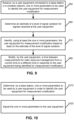
- FIG. 9 this figure is a flowchart performed by a UE for measurement modification, in accordance with an exemplary embodiment.
- FIG. 9 illustrates the operation of exemplary methods, a result of execution of computer program instructions embodied on a computer readable memory, functions performed by logic implemented in hardware, and/or interconnected means for performing functions in accordance with exemplary embodiments.
- FIG. 9 is performed by a UE 110, e.g., under control of a control module 140, at least in part.
- the UE 110 receives one or more parameters to be used to identify the user equipment for measurement modification.
- the UE 110 is connected to a base station 170 in a wireless network 100.
- the UE 110 determines an estimate of a level of signal variation for signals received at the UE 110.
- the UE 110 in block 970, identifies, using at least the one or more parameters, the user equipment for measurement modification based at least on the estimate of the level of signal variation.
- the UE 110 in block 980 modifies, by the user equipment, a time between measurements for radio resource management from a current time to a different time in response to the user equipment being identified for measurement modification.
- the modification in time between measurements may be similar to the previously described measurement relaxation.
- measurement relaxation allows the UE to perform fewer measurements over time (e.g., than currently performed under a current configuration), such as the UE will perform measurements less frequently, the UE is allowed to skip some measurements, the UE is allowed to determine when to perform measurements, and/or the UE will measure fewer cells or frequencies.
- the time between measurements is decreased, the UE can perform more measurements over time (e.g., than currently performed under a current configuration), such as the UE will perform measurements more frequently, the UE is not allowed to skip some measurements, the UE is not allowed to determine when to perform measurements, and/or the UE will measure more cells or frequencies.
- FIG. 10 is a flowchart performed by a base station for measurement modification, in accordance with an exemplary embodiment.
- FIG. 10 illustrates the operation of exemplary methods, a result of execution of computer program instructions embodied on a computer readable memory, functions performed by logic implemented in hardware, and/or interconnected means for performing functions in accordance with exemplary embodiments.
- FIG. 10 is performed by a base station 170, e.g., under control of a control module 150, at least in part.
- the BS 170 determines one or more parameters to be used by a UE 110 in order to identify the user equipment for measurement modification.
- the BS 170 in block 1020 signals the one or more parameters to the UE 110.
- a technical effect and advantage of one or more of the example embodiments disclosed herein is stationarity of heterogenous devices can be detected. Another technical effect and advantage of one or more of the example embodiments disclosed herein is that stationary UEs can decrease the signaling stemming from energy heavy mobility signaling procedures, thereby saving energy.
- circuitry may refer to one or more or all of the following:
- circuitry also covers an implementation of merely a hardware circuit or processor (or multiple processors) or portion of a hardware circuit or processor and its (or their) accompanying software and/or firmware.
- circuitry also covers, for example and if applicable to the particular claim element, a baseband integrated circuit or processor integrated circuit for a mobile device or a similar integrated circuit in server, a cellular network device, or other computing or network device.
- Embodiments herein may be implemented in software (executed by one or more processors), hardware (e.g., an application specific integrated circuit), or a combination of software and hardware.
- the software e.g., application logic, an instruction set
- a "computer-readable medium” may be any media or means that can contain, store, communicate, propagate or transport the instructions for use by or in connection with an instruction execution system, apparatus, or device, such as a computer, with one example of a computer described and depicted, e.g., in FIG. 1 .
- a computer-readable medium may comprise a computer-readable storage medium (e.g., memories 125, 155, 171 or other device) that may be any media or means that can contain, store, and/or transport the instructions for use by or in connection with an instruction execution system, apparatus, or device, such as a computer.
- a computer-readable storage medium does not comprise propagating signals.
- the different functions discussed herein may be performed in a different order and/or concurrently with each other. Furthermore, if desired, one or more of the above-described functions may be optional or may be combined.
Landscapes
- Engineering & Computer Science (AREA)
- Computer Networks & Wireless Communication (AREA)
- Signal Processing (AREA)
- Quality & Reliability (AREA)
- Physics & Mathematics (AREA)
- Electromagnetism (AREA)
- Computer Security & Cryptography (AREA)
- Mobile Radio Communication Systems (AREA)
Claims (12)
- Verfahren, das Folgendes umfasst:Empfangen von einem oder mehreren Parametern, die von einer Teilnehmereinrichtung zu verwenden sind, um die Teilnehmereinrichtung (110) für eine Messmodifikation zu identifizieren, durch die Teilnehmereinrichtung (110), die mit einer Basisstation (170) in einem drahtlosen Netzwerk verbunden ist;Bestimmen einer Schätzung eines Maßes einer Signalabweichung durch die Teilnehmereinrichtung für Signale, die an der Teilnehmereinrichtung (110) empfangen werden;Identifizieren der Teilnehmereinrichtung (110) für eine Messmodifikation unter Verwendung des einen oder der mehreren Parameter mindestens auf Basis der Schätzung des Maßes der Signalabweichung, wobei das Identifizieren der Teilnehmereinrichtung (110) für eine Messmodifikation das Bestimmen, dass die Teilnehmereinrichtung (110) stationär ist, und das Identifizieren der Teilnehmereinrichtung (110) als für eine Messmodifikation geeignet umfasst, weil die Teilnehmereinrichtung (110) stationär ist; undModifizieren einer Zeit zwischen Messungen für eine Funkressourcenverwaltung von einer aktuellen Zeit in eine andere Zeit durch die Teilnehmereinrichtung (110) in Reaktion darauf, dass die Teilnehmereinrichtung (110) für eine Messmodifikation identifiziert ist.
- Verfahren nach Anspruch 1, wobei die aktuelle Zeit und die andere Zeit via eine Signalisierung ausgelegt werden, die von der Teilnehmereinrichtung (110) von der Basisstation (170) empfangen wird.
- Verfahren nach einem der Ansprüche 1 oder 2, wobei das Bestimmen der Schätzung des Maßes der Signalabweichung einen oder mehrere Parameter verwendet, die sich auf einen Zustand der Teilnehmereinrichtung (110) beziehen.
- Verfahren nach Anspruch 3, wobei der eine oder die mehreren Parameter, die sich auf einen Zustand der Teilnehmereinrichtung (110) beziehen, eine Empfangsleistung umfassen; und/oderwobei der eine oder die mehreren Parameter, die sich auf einen Zustand der Teilnehmereinrichtung (110) beziehen, einen Standort der Teilnehmereinrichtung (110) in einer Zelle umfassen, die durch die Basisstation (170) gebildet wird; und/oderwobei der eine oder die mehreren Parameter, die sich auf einen Zustand der Teilnehmereinrichtung (110) beziehen, einen Antennentyp der Teilnehmereinrichtung (110) umfassen.
- Verfahren nach einem der Ansprüche 1 bis 4, wobei:das Bestimmen des Maßes der Signalabweichung, die an der Teilnehmereinrichtung (110) empfangen wird, das Auswählen von einer von mehreren Gruppen umfasst, die Abweichungen des Signals anzeigen; undwobei:das Bestimmen der ausgewählten der mehreren Gruppen Folgendes umfasst:A) Bestimmen, ob die Teilnehmereinrichtung (110) dazu ausgelegt ist, eine hohe Abweichung bei empfangenen Signalen aufzuweisen; undB) Bestimmen, ob die Teilnehmereinrichtung (110) einen Standort aufweist, der sich in einer äußeren Region einer Zelle oder nicht in der äußeren Region der Zelle befindet;das Bestimmen der ausgewählten der mehreren Gruppen Ergebnisse sowohl von (A) als auch von (B) verwendet, um die ausgewählte Gruppe zu bestimmen; undwobei:
das Bestimmen, ob die Teilnehmereinrichtung (110) dazu ausgelegt ist, eine hohe Abweichung bei empfangenen Signalen aufzuweisen, das Bestimmen, dass eine Fähigkeit der Teilnehmereinrichtung (110) eine Fähigkeit ist, die zu einer hohen Abweichung führt, und in Reaktion das Zuweisen der Teilnehmereinrichtung (110), eine hohe Abweichung zu haben, umfasst. - Verfahren nach Anspruch 5, wobei:der eine oder die mehreren Parameter, die zum Identifizieren der Teilnehmereinrichtung (110) für eine Messmodifikation zu verwenden sind, mehrere Parameter sind; unddas Identifizieren der Teilnehmereinrichtung (110) für eine Messmodifikation mindestens auf Basis der Schätzung des Maßes der Signalabweichung ferner das Verwenden der mehreren Parameter zusammen mit der Schätzung des Maßes der Signalabweichung umfasst, um die Teilnehmereinrichtung (110) für eine Messmodifikation zu identifizieren.
- Verfahren nach Anspruch 6, wobei die mehreren Parameter einen Schwellwert umfassen, und wobei das Identifizieren der Teilnehmereinrichtung (110) für eine Messmodifikation mindestens auf Basis der Schätzung des Maßes der Signalabweichung Folgendes umfasst:in Reaktion darauf, dass die Teilnehmereinrichtung (110) eine hohe Signalabweichung aufweist, Verwenden eines ersten der mehreren Parameter und des Schwellwerts durch die Teilnehmereinrichtung (110), um zu bestimmen, ob eine erste Bedingung erfüllt ist;in Reaktion darauf, dass die Teilnehmereinrichtung (110) eine mittlere Signalabweichung aufweist, Verwenden eines zweiten der mehreren Parameter und des Schwellwerts durch die Teilnehmereinrichtung (110), um zu bestimmen, ob eine zweite Bedingung erfüllt ist;andernfalls verwendet die UE (110) den Schwellwert, um zu bestimmen, ob eine dritte Bedingung erfüllt ist; undin Reaktion darauf, dass eine der ersten, der zweiten oder der dritten Bedingung erfüllt ist, Identifizieren der Teilnehmereinrichtung (110) für eine Messmodifikation; oderwobei die mehreren Parameter einen Schwellwert und einen ersten und einen zweiten Timerparameter umfassen, und wobei das Identifizieren der Teilnehmereinrichtung (110) für eine Messmodifikation mindestens auf Basis der Schätzung des Maßes der Signalabweichung Folgendes umfasst:Verwenden des ersten Timerparameters der mehreren Parameter durch die Teilnehmereinrichtung (110), um zu bestimmen, dass die Schätzung des Maßes der Signalvarianz die hohe Signalabweichung aufweist;in Reaktion darauf, dass die Teilnehmereinrichtung (110) die hohe Signalabweichung aufweist, Verwenden eines ersten der mehreren Parameter und des Schwellwerts durch die Teilnehmereinrichtung (110), um zu bestimmen, ob eine erste Bedingung erfüllt ist;Verwenden des zweiten Timerparameters der mehreren Parameter durch die Teilnehmereinrichtung (110), um zu bestimmen, dass die Schätzung des Maßes der Signalvarianz die mittlere Signalabweichung aufweist;in Reaktion darauf, dass die Teilnehmereinrichtung (110) die mittlere Signalabweichung aufweist, Verwenden eines zweiten der mehreren Parameter und des Schwellwerts durch die Teilnehmereinrichtung (110), um zu bestimmen, ob eine zweite Bedingung erfüllt ist;andernfalls verwendet die UE (110) den Schwellwert, um zu bestimmen, ob eine dritte Bedingung erfüllt ist; undin Reaktion darauf, dass eine der ersten, der zweiten oder der dritten Bedingung erfüllt ist, Identifizieren der Teilnehmereinrichtung (110) für eine Messmodifikation.
- Verfahren, das Folgendes umfasst:Bestimmen von einem oder mehreren Parametern, die von einer Teilnehmereinrichtung (110) zu verwenden sind, durch eine Basisstation (170), um die Teilnehmereinrichtung (110) für eine Messmodifikation zu identifizieren; undSignalisieren des einen oder der mehreren Parameter durch die Basisstation (170) an die Teilnehmereinrichtung (110), wobei der eine oder die mehreren Parameter, die von der Teilnehmereinrichtung (110) zu verwenden sind, um die Teilnehmereinrichtung (110) für eine Messmodifikation zu identifizieren, dem Bestimmen dienen, dass die Teilnehmereinrichtung (110) stationär und für eine Messmodifikation geeignet ist, weil die Teilnehmereinrichtung (110) stationär ist; undwobei die Messmodifikation eine Zeit zwischen Messungen für eine Funkressourcenverwaltung durch die Teilnehmereinrichtung von einer aktuellen Zeit in eine andere Zeit in Reaktion darauf anpassen soll, dass die Teilnehmereinrichtung (110) für eine Messmodifikation identifiziert ist, und wobei die Basisstation (170) die aktuelle Zeit und die andere Zeit an die Teilnehmereinrichtung (110) signalisiert.
- Verfahren nach Anspruch 8, wobei der eine oder die mehreren Parameter Parameter für mehrere Gruppen umfassen, die Abweichungen des Signals anzeigen, Werte der Parameter für die mehreren Gruppen von der Basisstation (170) unter Verwendung von einem oder mehreren der folgenden Prozesse bestimmt werden:Verwenden von Orts- oder Zell- oder sowohl von Orts- als auch von Zellmesskampagnen;Aufbauen eines Schätzers, der Benutzeruplinkreferenzsignale verfolgt; oderVerwenden von Parametern, die durch eine Funkressourcenmessmodifikation beeinträchtigt werden;das ferner das Koordinieren von Ergebnissen des einen oder der mehreren Prozesse umfasst, um die Werte der Parameter für die mehreren Gruppen einzustellen; und/oderwobei die Parameter für die mehreren Gruppen Parameter für eine mittlere Abweichungsgruppe und eine hohe Abweichungsgruppe umfassen;wobei die Parameter für die mehreren Gruppen ferner einen Schwellwert oder den Schwellwert und einen ersten und einen zweiten Timerparameter umfassen.
- Computerprogramm, das einen Code zum Durchführen der Verfahren nach einem der Ansprüche 1 bis 7 umfasst, wenn er von einem Prozessor einer Teilnehmereinrichtung (110) ausgeführt wird.
- Teilnehmereinrichtung (110), die Mittel zum Durchführen von Folgendem umfasst:Empfangen von einem oder mehreren Parametern, die von der Teilnehmereinrichtung zu verwenden sind, um die Teilnehmereinrichtung (110) für eine Messmodifikation zu identifizieren, durch die Teilnehmereinrichtung (110), die mit einer Basisstation (170) in einem drahtlosen Netzwerk verbunden ist;Bestimmen einer Schätzung eines Maßes einer Signalabweichung durch die Teilnehmereinrichtung für Signale, die an der Teilnehmereinrichtung (110) empfangen werden;Identifizieren der Teilnehmereinrichtung (110) für eine Messmodifikation unter Verwendung des einen oder der mehreren Parameter mindestens auf Basis der Schätzung des Maßes der Signalabweichung, wobei das Identifizieren der Teilnehmereinrichtung (110) für eine Messmodifikation das Bestimmen, dass die Teilnehmereinrichtung (110) stationär ist, und das Identifizieren der Teilnehmereinrichtung (110) als für eine Messmodifikation geeignet umfasst, weil die Teilnehmereinrichtung (110) stationär ist; undModifizieren einer Zeit zwischen Messungen für eine Funkressourcenverwaltung von einer aktuellen Zeit in eine andere Zeit durch die Teilnehmereinrichtung (110) in Reaktion darauf, dass die Teilnehmereinrichtung (110) für eine Messmodifikation identifiziert ist.
- Basisstation, die Mittel zum Durchführen von Folgendem umfasst:Bestimmen von einem oder mehreren Parametern, die von einer Teilnehmereinrichtung (110) zu verwenden sind, durch die Basisstation (170), um die Teilnehmereinrichtung (110) für eine Messmodifikation zu identifizieren; undSignalisieren des einen oder der mehreren Parameter durch die Basisstation an die Teilnehmereinrichtung (110), wobei der eine oder die mehreren Parameter, die von der Teilnehmereinrichtung (110) zu verwenden sind, um die Teilnehmereinrichtung (110) für eine Messmodifikation zu identifizieren, dem Bestimmen dienen, dass die Teilnehmereinrichtung (110) stationär und für eine Messmodifikation geeignet ist, weil die Teilnehmereinrichtung (110) stationär ist.
Applications Claiming Priority (1)
| Application Number | Priority Date | Filing Date | Title |
|---|---|---|---|
| PCT/US2020/056659 WO2022086522A1 (en) | 2020-10-21 | 2020-10-21 | Dynamic ue signal level correction for measurement modification and/or stationarity detection |
Publications (4)
| Publication Number | Publication Date |
|---|---|
| EP4233338A1 EP4233338A1 (de) | 2023-08-30 |
| EP4233338A4 EP4233338A4 (de) | 2024-07-03 |
| EP4233338C0 EP4233338C0 (de) | 2025-06-04 |
| EP4233338B1 true EP4233338B1 (de) | 2025-06-04 |
Family
ID=81289343
Family Applications (1)
| Application Number | Title | Priority Date | Filing Date |
|---|---|---|---|
| EP20958872.2A Active EP4233338B1 (de) | 2020-10-21 | 2020-10-21 | Dynamische ue-signalpegelkorrektur für messmodifikation und/oder stationaritätserkennung |
Country Status (5)
| Country | Link |
|---|---|
| US (1) | US20230412290A1 (de) |
| EP (1) | EP4233338B1 (de) |
| CN (1) | CN117121531A (de) |
| ES (1) | ES3035483T3 (de) |
| WO (1) | WO2022086522A1 (de) |
Families Citing this family (2)
| Publication number | Priority date | Publication date | Assignee | Title |
|---|---|---|---|---|
| CN115515156A (zh) * | 2021-06-23 | 2022-12-23 | 索尼集团公司 | 用于无线通信系统的电子设备、方法和存储介质 |
| CN115918118A (zh) * | 2021-07-29 | 2023-04-04 | 北京小米移动软件有限公司 | 基于测量放松机制的通信方法、装置及存储介质 |
Citations (1)
| Publication number | Priority date | Publication date | Assignee | Title |
|---|---|---|---|---|
| EP2092666B1 (de) * | 2006-12-13 | 2020-03-18 | Samsung Electronics Co., Ltd. | Messverfahren und vorrichtung für benutzergeräte mit variabler messperiode in einem mobilkommunikationssystem |
Family Cites Families (14)
| Publication number | Priority date | Publication date | Assignee | Title |
|---|---|---|---|---|
| US9485683B2 (en) * | 2012-05-31 | 2016-11-01 | Interdigital Patent Holdings, Inc. | Sensing measurement configuration and reporting in a long term evolution system operating over license exempt bands |
| EP3117655B1 (de) * | 2014-03-14 | 2020-11-18 | Nokia Solutions and Networks Oy | Rrm-messberichte ruhender zellen |
| US20160234747A1 (en) | 2015-02-05 | 2016-08-11 | Htc Corporation | Mobile device and method for handling neighbor cell measurement |
| US9961580B2 (en) | 2015-06-26 | 2018-05-01 | Intel IP Corporation | Mobile terminal devices and methods of performing radio measurements |
| WO2017051067A1 (en) * | 2015-09-24 | 2017-03-30 | Nokia Technologies Oy | Method of ue autonomous measurement related actions upon implicit triggers |
| US20170142777A1 (en) * | 2015-11-13 | 2017-05-18 | Alcatel-Lucent Usa Inc. | Modifying inactivity timers for user equipment in a wireless communication system |
| US9794753B1 (en) * | 2016-04-15 | 2017-10-17 | Infinitekey, Inc. | System and method for establishing real-time location |
| TWI672965B (zh) * | 2017-05-12 | 2019-09-21 | 聯發科技股份有限公司 | 優化喚醒和相鄰小區測量方法及其使用者設備 |
| WO2019066559A1 (en) * | 2017-09-28 | 2019-04-04 | Lg Electronics Inc. | METHOD FOR DETERMINING THE MOBILITY STATUS OF A UE AND DEVICE SUPPORTING IT |
| WO2020069155A2 (en) * | 2018-09-28 | 2020-04-02 | Intel Corporation | Techniques to reduce radio resource management measurements and user equipment power consumption |
| US20210076275A1 (en) * | 2019-10-02 | 2021-03-11 | Candy Yiu | Apparatus, system and method to configure conditions for radio resource management measurement relaxation in a new radio network |
| US12200525B2 (en) * | 2020-05-08 | 2025-01-14 | Qualcomm Incorporated | RRM relaxation for stationary user equipment |
| EP4161134B1 (de) * | 2020-08-03 | 2024-09-25 | Guangdong Oppo Mobile Telecommunications Corp., Ltd. | Zellenmessungsanzeigeverfahren, endgerätevorrichtung und netzwerkvorrichtung |
| EP4201110A4 (de) * | 2020-10-08 | 2023-10-18 | Apple Inc. | Relaxation der signalisierungseigenschaftsbeurteilung für energiesparen bei benutzergeräten |
-
2020
- 2020-10-21 CN CN202080106537.XA patent/CN117121531A/zh active Pending
- 2020-10-21 US US18/033,102 patent/US20230412290A1/en active Pending
- 2020-10-21 ES ES20958872T patent/ES3035483T3/es active Active
- 2020-10-21 WO PCT/US2020/056659 patent/WO2022086522A1/en not_active Ceased
- 2020-10-21 EP EP20958872.2A patent/EP4233338B1/de active Active
Patent Citations (1)
| Publication number | Priority date | Publication date | Assignee | Title |
|---|---|---|---|---|
| EP2092666B1 (de) * | 2006-12-13 | 2020-03-18 | Samsung Electronics Co., Ltd. | Messverfahren und vorrichtung für benutzergeräte mit variabler messperiode in einem mobilkommunikationssystem |
Also Published As
| Publication number | Publication date |
|---|---|
| EP4233338A4 (de) | 2024-07-03 |
| CN117121531A (zh) | 2023-11-24 |
| EP4233338A1 (de) | 2023-08-30 |
| WO2022086522A1 (en) | 2022-04-28 |
| ES3035483T3 (en) | 2025-09-04 |
| US20230412290A1 (en) | 2023-12-21 |
| EP4233338C0 (de) | 2025-06-04 |
Similar Documents
| Publication | Publication Date | Title |
|---|---|---|
| EP3874828B1 (de) | Verfahren zur verringerung des stromverbrauchs für messkonfigurationen | |
| CN112840707B (zh) | 适配ue rrm测量用于节电的方法 | |
| US11751183B2 (en) | CORESET and QCL association in beam recovery procedure | |
| US11956683B2 (en) | Robust beam failure recovery using a non-serving cell | |
| US10200895B2 (en) | Radio link monitoring methods for wireless systems with multiple coverage levels | |
| US20200154327A1 (en) | Cell ranking in multi beam system | |
| US20160157116A1 (en) | Methods, apparatuses, and computer-readable storage media for inter-frequency small cell detection and reporting | |
| CN114258130B (zh) | 由探测参考信号触发的定位参考信号传输 | |
| CN114747289B (zh) | 基于单时机周期值来适配最大允许的cca失败 | |
| EP4233338B1 (de) | Dynamische ue-signalpegelkorrektur für messmodifikation und/oder stationaritätserkennung | |
| US12022344B2 (en) | Cell ranking in multi beam system | |
| WO2024030134A1 (en) | Adjusting radio link quality monitoring based on potential cli such as for advanced duplexing cases | |
| CN116114322B (zh) | Csi-rs测量的处理 | |
| US20240267768A1 (en) | Relaxation compensation for improved system performance | |
| WO2022016493A1 (en) | Radio resource management measurement relaxation and cell reselection | |
| WO2023133892A1 (en) | Enhanced user equipment report | |
| US12549993B2 (en) | Enhanced User Equipment report | |
| WO2024183066A1 (en) | Positioning management | |
| EP4701090A1 (de) | Verfahren, vorrichtung und computerprogramm | |
| WO2026041944A1 (en) | Ueibm event to update active tci-state list | |
| US20240306004A1 (en) | Beam Management for High-Speed Train | |
| WO2026013463A1 (en) | Provisioning of lpwa carrier as a fallback for broadband services | |
| WO2025088512A1 (en) | Measurement gap for energy harvesting devices | |
| WO2026013462A1 (en) | Provisioning of lpwa carrier as a fallback for broadband services |
Legal Events
| Date | Code | Title | Description |
|---|---|---|---|
| STAA | Information on the status of an ep patent application or granted ep patent |
Free format text: STATUS: THE INTERNATIONAL PUBLICATION HAS BEEN MADE |
|
| PUAI | Public reference made under article 153(3) epc to a published international application that has entered the european phase |
Free format text: ORIGINAL CODE: 0009012 |
|
| STAA | Information on the status of an ep patent application or granted ep patent |
Free format text: STATUS: REQUEST FOR EXAMINATION WAS MADE |
|
| 17P | Request for examination filed |
Effective date: 20230516 |
|
| AK | Designated contracting states |
Kind code of ref document: A1 Designated state(s): AL AT BE BG CH CY CZ DE DK EE ES FI FR GB GR HR HU IE IS IT LI LT LU LV MC MK MT NL NO PL PT RO RS SE SI SK SM TR |
|
| DAV | Request for validation of the european patent (deleted) | ||
| DAX | Request for extension of the european patent (deleted) | ||
| A4 | Supplementary search report drawn up and despatched |
Effective date: 20240603 |
|
| RIC1 | Information provided on ipc code assigned before grant |
Ipc: H04W 52/02 20090101ALN20240527BHEP Ipc: H04W 24/08 20090101ALI20240527BHEP Ipc: H04W 40/24 20090101ALI20240527BHEP Ipc: H04W 24/10 20090101ALI20240527BHEP Ipc: H04W 24/02 20090101ALI20240527BHEP Ipc: H04W 24/00 20090101AFI20240527BHEP |
|
| GRAP | Despatch of communication of intention to grant a patent |
Free format text: ORIGINAL CODE: EPIDOSNIGR1 |
|
| STAA | Information on the status of an ep patent application or granted ep patent |
Free format text: STATUS: GRANT OF PATENT IS INTENDED |
|
| RIC1 | Information provided on ipc code assigned before grant |
Ipc: H04W 52/02 20090101ALN20250123BHEP Ipc: H04W 24/08 20090101ALI20250123BHEP Ipc: H04W 40/24 20090101ALI20250123BHEP Ipc: H04W 24/10 20090101ALI20250123BHEP Ipc: H04W 24/02 20090101ALI20250123BHEP Ipc: H04W 24/00 20090101AFI20250123BHEP |
|
| RIC1 | Information provided on ipc code assigned before grant |
Ipc: H04W 52/02 20090101ALN20250203BHEP Ipc: H04W 24/08 20090101ALI20250203BHEP Ipc: H04W 40/24 20090101ALI20250203BHEP Ipc: H04W 24/10 20090101ALI20250203BHEP Ipc: H04W 24/02 20090101ALI20250203BHEP Ipc: H04W 24/00 20090101AFI20250203BHEP |
|
| INTG | Intention to grant announced |
Effective date: 20250226 |
|
| GRAS | Grant fee paid |
Free format text: ORIGINAL CODE: EPIDOSNIGR3 |
|
| GRAA | (expected) grant |
Free format text: ORIGINAL CODE: 0009210 |
|
| STAA | Information on the status of an ep patent application or granted ep patent |
Free format text: STATUS: THE PATENT HAS BEEN GRANTED |
|
| AK | Designated contracting states |
Kind code of ref document: B1 Designated state(s): AL AT BE BG CH CY CZ DE DK EE ES FI FR GB GR HR HU IE IS IT LI LT LU LV MC MK MT NL NO PL PT RO RS SE SI SK SM TR |
|
| REG | Reference to a national code |
Ref country code: GB Ref legal event code: FG4D |
|
| REG | Reference to a national code |
Ref country code: CH Ref legal event code: EP |
|
| REG | Reference to a national code |
Ref country code: IE Ref legal event code: FG4D |
|
| U01 | Request for unitary effect filed |
Effective date: 20250604 |
|
| U07 | Unitary effect registered |
Designated state(s): AT BE BG DE DK EE FI FR IT LT LU LV MT NL PT RO SE SI Effective date: 20250611 |
|
| REG | Reference to a national code |
Ref country code: ES Ref legal event code: FG2A Ref document number: 3035483 Country of ref document: ES Kind code of ref document: T3 Effective date: 20250904 |
|
| PG25 | Lapsed in a contracting state [announced via postgrant information from national office to epo] |
Ref country code: NO Free format text: LAPSE BECAUSE OF FAILURE TO SUBMIT A TRANSLATION OF THE DESCRIPTION OR TO PAY THE FEE WITHIN THE PRESCRIBED TIME-LIMIT Effective date: 20250904 Ref country code: GR Free format text: LAPSE BECAUSE OF FAILURE TO SUBMIT A TRANSLATION OF THE DESCRIPTION OR TO PAY THE FEE WITHIN THE PRESCRIBED TIME-LIMIT Effective date: 20250905 |
|
| PG25 | Lapsed in a contracting state [announced via postgrant information from national office to epo] |
Ref country code: PL Free format text: LAPSE BECAUSE OF FAILURE TO SUBMIT A TRANSLATION OF THE DESCRIPTION OR TO PAY THE FEE WITHIN THE PRESCRIBED TIME-LIMIT Effective date: 20250604 |
|
| U20 | Renewal fee for the european patent with unitary effect paid |
Year of fee payment: 6 Effective date: 20250909 |
|
| PG25 | Lapsed in a contracting state [announced via postgrant information from national office to epo] |
Ref country code: HR Free format text: LAPSE BECAUSE OF FAILURE TO SUBMIT A TRANSLATION OF THE DESCRIPTION OR TO PAY THE FEE WITHIN THE PRESCRIBED TIME-LIMIT Effective date: 20250604 |
|
| PG25 | Lapsed in a contracting state [announced via postgrant information from national office to epo] |
Ref country code: RS Free format text: LAPSE BECAUSE OF FAILURE TO SUBMIT A TRANSLATION OF THE DESCRIPTION OR TO PAY THE FEE WITHIN THE PRESCRIBED TIME-LIMIT Effective date: 20250904 |
|
| PG25 | Lapsed in a contracting state [announced via postgrant information from national office to epo] |
Ref country code: IS Free format text: LAPSE BECAUSE OF FAILURE TO SUBMIT A TRANSLATION OF THE DESCRIPTION OR TO PAY THE FEE WITHIN THE PRESCRIBED TIME-LIMIT Effective date: 20251004 |
|
| PG25 | Lapsed in a contracting state [announced via postgrant information from national office to epo] |
Ref country code: SM Free format text: LAPSE BECAUSE OF FAILURE TO SUBMIT A TRANSLATION OF THE DESCRIPTION OR TO PAY THE FEE WITHIN THE PRESCRIBED TIME-LIMIT Effective date: 20250604 |
|
| PG25 | Lapsed in a contracting state [announced via postgrant information from national office to epo] |
Ref country code: CZ Free format text: LAPSE BECAUSE OF FAILURE TO SUBMIT A TRANSLATION OF THE DESCRIPTION OR TO PAY THE FEE WITHIN THE PRESCRIBED TIME-LIMIT Effective date: 20250604 |
|
| PG25 | Lapsed in a contracting state [announced via postgrant information from national office to epo] |
Ref country code: SK Free format text: LAPSE BECAUSE OF FAILURE TO SUBMIT A TRANSLATION OF THE DESCRIPTION OR TO PAY THE FEE WITHIN THE PRESCRIBED TIME-LIMIT Effective date: 20250604 |
|
| PGFP | Annual fee paid to national office [announced via postgrant information from national office to epo] |
Ref country code: ES Payment date: 20251105 Year of fee payment: 6 |
|
| PLBE | No opposition filed within time limit |
Free format text: ORIGINAL CODE: 0009261 |
|
| STAA | Information on the status of an ep patent application or granted ep patent |
Free format text: STATUS: NO OPPOSITION FILED WITHIN TIME LIMIT |
|
| REG | Reference to a national code |
Ref country code: CH Ref legal event code: L10 Free format text: ST27 STATUS EVENT CODE: U-0-0-L10-L00 (AS PROVIDED BY THE NATIONAL OFFICE) Effective date: 20260416 |