EP4232887B1 - Eingabevorrichtung mit drehbaren betätigungsknöpfen - Google Patents
Eingabevorrichtung mit drehbaren betätigungsknöpfen Download PDFInfo
- Publication number
- EP4232887B1 EP4232887B1 EP21841102.3A EP21841102A EP4232887B1 EP 4232887 B1 EP4232887 B1 EP 4232887B1 EP 21841102 A EP21841102 A EP 21841102A EP 4232887 B1 EP4232887 B1 EP 4232887B1
- Authority
- EP
- European Patent Office
- Prior art keywords
- input device
- certain embodiments
- rotatable control
- image
- manipulation
- Prior art date
- Legal status (The legal status is an assumption and is not a legal conclusion. Google has not performed a legal analysis and makes no representation as to the accuracy of the status listed.)
- Active
Links
Images


Classifications
-
- G—PHYSICS
- G06—COMPUTING OR CALCULATING; COUNTING
- G06F—ELECTRIC DIGITAL DATA PROCESSING
- G06F3/00—Input arrangements for transferring data to be processed into a form capable of being handled by the computer; Output arrangements for transferring data from processing unit to output unit, e.g. interface arrangements
- G06F3/01—Input arrangements or combined input and output arrangements for interaction between user and computer
- G06F3/02—Input arrangements using manually operated switches, e.g. using keyboards or dials
- G06F3/0202—Constructional details or processes of manufacture of the input device
- G06F3/021—Arrangements integrating additional peripherals in a keyboard, e.g. card or barcode reader, optical scanner
- G06F3/0213—Arrangements providing an integrated pointing device in a keyboard, e.g. trackball, mini-joystick
-
- G—PHYSICS
- G06—COMPUTING OR CALCULATING; COUNTING
- G06F—ELECTRIC DIGITAL DATA PROCESSING
- G06F3/00—Input arrangements for transferring data to be processed into a form capable of being handled by the computer; Output arrangements for transferring data from processing unit to output unit, e.g. interface arrangements
- G06F3/01—Input arrangements or combined input and output arrangements for interaction between user and computer
- G06F3/03—Arrangements for converting the position or the displacement of a member into a coded form
- G06F3/033—Pointing devices displaced or positioned by the user, e.g. mice, trackballs, pens or joysticks; Accessories therefor
- G06F3/0354—Pointing devices displaced or positioned by the user, e.g. mice, trackballs, pens or joysticks; Accessories therefor with detection of 2D relative movements between the device, or an operating part thereof, and a plane or surface, e.g. 2D mice, trackballs, pens or pucks
- G06F3/03547—Touch pads, in which fingers can move on a surface
-
- G—PHYSICS
- G06—COMPUTING OR CALCULATING; COUNTING
- G06F—ELECTRIC DIGITAL DATA PROCESSING
- G06F3/00—Input arrangements for transferring data to be processed into a form capable of being handled by the computer; Output arrangements for transferring data from processing unit to output unit, e.g. interface arrangements
- G06F3/01—Input arrangements or combined input and output arrangements for interaction between user and computer
- G06F3/03—Arrangements for converting the position or the displacement of a member into a coded form
- G06F3/033—Pointing devices displaced or positioned by the user, e.g. mice, trackballs, pens or joysticks; Accessories therefor
- G06F3/0362—Pointing devices displaced or positioned by the user, e.g. mice, trackballs, pens or joysticks; Accessories therefor with detection of 1D translations or rotations of an operating part of the device, e.g. scroll wheels, sliders, knobs, rollers or belts
-
- G—PHYSICS
- G06—COMPUTING OR CALCULATING; COUNTING
- G06F—ELECTRIC DIGITAL DATA PROCESSING
- G06F3/00—Input arrangements for transferring data to be processed into a form capable of being handled by the computer; Output arrangements for transferring data from processing unit to output unit, e.g. interface arrangements
- G06F3/01—Input arrangements or combined input and output arrangements for interaction between user and computer
- G06F3/048—Interaction techniques based on graphical user interfaces [GUI]
- G06F3/0484—Interaction techniques based on graphical user interfaces [GUI] for the control of specific functions or operations, e.g. selecting or manipulating an object, an image or a displayed text element, setting a parameter value or selecting a range
- G06F3/04845—Interaction techniques based on graphical user interfaces [GUI] for the control of specific functions or operations, e.g. selecting or manipulating an object, an image or a displayed text element, setting a parameter value or selecting a range for image manipulation, e.g. dragging, rotation, expansion or change of colour
-
- G—PHYSICS
- G06—COMPUTING OR CALCULATING; COUNTING
- G06F—ELECTRIC DIGITAL DATA PROCESSING
- G06F3/00—Input arrangements for transferring data to be processed into a form capable of being handled by the computer; Output arrangements for transferring data from processing unit to output unit, e.g. interface arrangements
- G06F3/01—Input arrangements or combined input and output arrangements for interaction between user and computer
- G06F3/048—Interaction techniques based on graphical user interfaces [GUI]
- G06F3/0484—Interaction techniques based on graphical user interfaces [GUI] for the control of specific functions or operations, e.g. selecting or manipulating an object, an image or a displayed text element, setting a parameter value or selecting a range
- G06F3/0485—Scrolling or panning
-
- G—PHYSICS
- G06—COMPUTING OR CALCULATING; COUNTING
- G06F—ELECTRIC DIGITAL DATA PROCESSING
- G06F2203/00—Indexing scheme relating to G06F3/00 - G06F3/048
- G06F2203/048—Indexing scheme relating to G06F3/048
- G06F2203/04806—Zoom, i.e. interaction techniques or interactors for controlling the zooming operation
Definitions
- the disclosed technology relates to an ergonomic input device for a user to repetitively manipulate an image displayed on a user interface (UI) of a computer, and more particularly, relates to apparatuses having a plurality of knobs positioned for the user to pan in multiple directions and zoom the image displayed on the UI while minimizing the risk of developing musculoskeletal disorders (MSD).
- UI user interface
- MSD musculoskeletal disorders
- US2003/0043114 discloses a handheld data processing device with input controls on upper and lower surfaces.
- the following description is provided in the context of an ergonomic computer-implemented system and method for a pathologist to repetitively manipulate selected portions of a digital image displayed on a display screen.
- the digital images can be from laboratory samples of body tissue.
- the pathologist studies the digital image to determine the causes and effects of diseases for diagnostic or forensic purposes. It will be appreciated, however, that the disclosed systems and methods have greater utility and may be used for different images outside of the medical field.
- Input devices can include a keyboard to enter text into the UI in combination with a mouse for scrolling the UI.
- a mouse can include many buttons or inputs to accomplish multiple manipulations of an image. However, even where the mouse allows multiple manipulations, those manipulations are still being input by a single hand of the user requiring a complex set of finger manipulations of the single hand. Further, while a mouse is designed to allow multiple manipulations of the image, the sensitivity provided by the mouse is inadequate to provide precise manipulation due to user fatigue. Certain industries require repetitive manipulation of an image. The use of a mouse for this purpose is not only inconvenient but can lead to musculoskeletal disorders (MSD).
- MSD musculoskeletal disorders
- a comparative study of input devices including a mouse, a 6DOF navigator, and a touch pad identified desirable characteristics of a preferred input device.
- the three different input device implementations were compared in terms of time to diagnose, perceived workload and users' preferences. These characteristics included ease of navigation so that the pathologist's effort can be put into the review of the case, and therefore, a low perceived workload. See " A comparative study of input devices for digital slide navigation" from the 2nd Nordic Symposium on Digital Pathology . However, the study found that a quick and seamless integration between input devices and the navigation of digital slides still remains a key barrier for many pathologists to "go digital.”
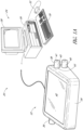
- FIGURE 1A illustrates a diagnostic system 20 that includes an input device 22 and an optional computer system 24.
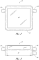
- FIGURE 2 is a top plan view of the input device 22 from Figure 1A .
- the exemplary diagnostic system 20 embodies several features of a preferred embodiment of the present invention.
- the diagnostic system 20 incorporates software, methods, and systems for manipulating an image displayed by a user interface (UI) of a computer 26.
- UI user interface
- the diagnostic system 20 receives input from a user via one or more rotatable control knobs 36, 38, 40 to manipulate a digital image.
- the diagnostic system 20 includes an input device 22 with several rotatable control knobs 36, 38, 40 to mimic certain mouse and/or keyboard functions for zooming and panning a digital slide image.
- one of the one or more rotatable control knobs 36, 38, 40 is similar to changing magnifications of a microscope but in a more continuous fashion digitally from low to high or high to low magnification (zooming) than otherwise switching objectives with various magnifications in a microscope.
- Another of the one or more rotatable control knobs 36, 38, 40 is similar to an up/down stage control of the microscope.
- Another of the one or more rotatable control knobs 36, 38, 40 is similar to a left/right stage control of the microscope.
- the input device 22 is configured as part of the diagnostic system 20.
- the one or more rotatable control knobs 36, 38, 40 can be coupled to any components of the diagnostic system 20.
- the input device 22 is configured as part of the computer system 24.
- the input device 22 is configured as a monitor 28.
- the one or more rotatable control knobs 36, 38, 40 can be coupled to the monitor 28.
- the input device 22 is configured as the computer 26.
- the one or more rotatable control knobs 36, 38, 40 can be coupled to the computer 26.
- the input device 22 comprises four rotatable control knobs.
- the fourth rotatable control knob provides focus stacking or z-stack.
- Focus stacking is a digital image processing technique which combines multiple images taken at different focus distances to give a resulting image with a greater depth of field (DOF) than any of the individual source images.
- DOE depth of field
- each of the one or more rotatable control knobs 36, 38, 40 comprises top 41 and bottom 43 surfaces, and an outer perimeter 45.
- each of the one or more rotatable control knobs 36, 38, 40 is secured to the input device 22 via a cylindrical shaft (not shown).
- each of the one or more rotatable control knobs 36, 38, 40 is secured to its respective shaft by a fastener which is inserted through a hole in the top surface 41.
- the one or more rotatable control knobs 36, 38, 40 can be constructed out of any rigid, durable material, such as plastic, metal or hard rubber.
- the outer perimeter 45 has a tapering shape.
- each of the one or more rotatable control knobs 36, 38, 40 comprises a rotary encoder.
- the rotary encoder is configured to convert the angular position or motion of the one or more rotatable control knobs 36, 38, 40 to analog or digital output signals.
- each of the rotary encoders is connected to the microcontroller 49 via associated electronic circuitry.
- the outer perimeter 45 is optionally a friction surface.
- the friction surface can be made out of any material which permits a user to easily rotate the one or more rotatable control knobs 36, 38, 40 with his or her fingers.
- the outer perimeter 45 may include no materials in addition to that of the outer perimeter 45, but may simply comprise an abrasive surface, or friction-generating pattern machined or molded onto the outer perimeter 45 of the one or more rotatable control knobs 36, 38, 40.
- one or more rotatable control knobs 36, 38, 40 are knurled and suitable for light adjustment work and fine-tuning.
- the top surface 41 of the one or more rotatable control knobs 36, 38, 40 can further include a line (not shown) extending from the outer perimeter 45 of the one or more rotatable control knobs 36, 38, 40, towards the center of the one or more rotatable control knobs 36, 38, 40.
- the line may serve as a visual indicator to indicate to the user or pathologist the degree of rotation of the one or more rotatable control knobs 36, 38, 40.
- the locations of the one or more rotatable control knobs 36, 38, 40 relative to the input device 22 are adjustable.
- the one or more rotatable control knobs 36, 38, 40 can be raised or lowered relative to the input device 22 to change a height of the one or more rotatable control knobs 36, 38, 40 relative to a table or other support surface of the input device 22. In this way, the user or pathologist can adjust the height of the one or more rotatable control knobs 36, 38, 40 to improve ergonomics.
- an adjustable connector (not shown) connects the one or more rotatable control knobs 36, 38, 40 to the housing 34.
- the input device 22 includes one or more supporting legs to adjust an angle between the user or pathologist and the input device 22 to improve ergonomics. For example, in certain embodiments, the angle is adjusted by the user stretching out or pulling back the one or more supporting legs. In certain embodiments, the one or more supporting legs are positioned close to a back side of the input device 22. In certain embodiments, the one or more supporting legs can be positioned close to a back side 62 on the bottom surface.
- the input device 22 includes one or more recesses to receive the one or more supporting legs when the supporting legs are pulled back against the bottom surface.
- the bottom surface of the input device 22 is in complete contact with the table or other support surface, and no angle is formed between the input device 22 and the table.
- the one or more supporting legs are turned for a certain angle to extend out of the bottom surface an angle between the table and the input device 22 is then formed, and the top surface of the input device 22 is slightly inclined toward the user or pathologist.
- the one or more rotatable control knobs 36, 38, 40 are removable from the housing 34.
- the housing 34 comprises a connector (not shown) configured to removably receive a portion of at least one of the one or more rotatable control knobs 36, 38, 40.
- the connector is a USB connector.
- the USB connector is disposed on the first or second ends of the input device 22. A portion of the one or more rotatable control knobs 36, 38, 40 that is compatible with the USB connector is engaged with the USB connector on the input device 22. When engaged, the functionality of the one or more rotatable control knobs 36, 38, 40 is the same as described with respect to Figure 1A .
- the one or more rotatable control knobs 36, 38, 40 can be added to an input device, such as the keyboard 30, if the input device or keyboard 30 includes the USB connector.
- the connector is not limited to a USB connector, and instead can be any connector known to a person having ordinary skill in the art.
- the one or more rotatable control knobs 36, 38, 40 comprise a microcontroller 49. In certain embodiments, the one or more rotatable control knobs 36, 38, 40 comprise a rotary encoder. Having the microcontroller 49 and/or the rotary encoder disposed in the one or more rotatable knobs 36, 38, 40 may be advantageous when the one or more rotatable knobs 36, 38, 40 are removable from the housing 34. In certain embodiments, the microcontroller 49 is configured to receive a position and/or zoom signal from the rotary encoder associated with the rotatable control knob 36, 38, 40 and convert the position and/or zoom signal to an instruction for the computer 24 to manipulate the image displayed by the UI.
- the microcontroller 49 can send the converted position and/or zoom signal via USB to the computer 24.
- the microcontroller 49 and/or the rotary encoder are disposed in the housing 34 and/or shared by more than one of the rotatable control knobs 36, 38, 40.
- the microcontroller 49 is shared with other inputs to the input device 22 such as, for example, the touch pad 42 and/or the keys of a keyboard (see FIGURES 6-10 ).
- FIGURE 3 is a front view of the input device 22 of Figure 2 .
- the input device 22 can be used as a standalone device or in combination with the computer system 24. When used as a standalone device, the input device 22 can include components of the computer system 24.
- the input device 22 includes at least a processor, memory, and a display.
- the input device 22 connects to the computer system 24 via a wired or wireless connection.
- the input device 22 can be directly connected to a wired or wireless network without being connected to the computer system 24.
- the network includes one or more servers.
- the computer system 24 includes additional input devices, such as a keyboard 30 and a pointing device such as a mouse 32.
- Other input devices (not shown) that may be part of the computer system 24 include a touch pad, trackpad, joystick, game pad, or the like.
- the input device 22 is configured as a keyboard 50.
- the input device 22 is not limited to the illustrated configurations and can be configured as any type of peripheral device (e.g., touch pad, trackpad, joystick, game pad, or the like) that includes one or more rotatable control knobs 36, 38, 40 to manipulate a digital image.
- the input device 22 further includes a touch pad 42 in combination with the one or more rotatable control knobs 36, 38, 40.
- the touch pad 42 is employed by the user or pathologist for annotation or drawing and slide selection.
- the touch pad 42 can be any appropriate shape, such as a square, rectangular, diamond, circular, cross, or oval.
- the input device 22 need not include the touch pad 42.
- the mouse 32 is employed instead of the touch pad 42 for annotation or drawing and slide selection.
- FIGURE 4 is a right side view of the input device 22 of Figure 2 .
- FIGURE 5 is a left side view of the input device 22 of Figure 2 .
- the input device 22 is operatively connected to the computer 26 and is configured for panning up/down, panning left/right, and zooming an image in multiple axes relative to the display screen of the monitor 28. In this way, the input device 22 is configured for two-handed functionality with the one or more rotatable control knobs 36, 38, 40.
- a method for a user or pathologist to manipulate an image displayed on a user interface is disclosed.
- the image is a scanned digital image.
- the scanned digital image is of a tissue sample for biopsy.
- the process begins by displaying the image on the UI.
- the process moves to rotating a first control knob to perform a first manipulation of the scanned digital image on the UI.
- the process moves to rotating a second control knob to perform a second manipulation of the scanned digital image on the UI.
- the second manipulation is different from the first manipulation.
- the process moves to rotating a third control knob to perform a third manipulation of the scanned digital image on the UI.
- the third manipulation is different from the first manipulation and the second manipulation.
- the process moves to adding annotations to and/or selecting the manipulated image.
- the annotated and/or selected image is then analyzed.
- the input device 22 comprises a housing 34.
- the housing 34 has a left end and a right end.
- at least one of the rotatable control knobs 36, 38, 40 is disposed on each of the left and right ends of the housing 34.
- the housing 34 includes two rotatable control knobs 36, 38, 40 on the right end of the housing 34.
- the housing 34 includes two rotatable control knobs 36, 38, 40 on the left end of the housing 34.
- One of the rotatable control knobs 36, 38, 40 is configured for the user to perform a first manipulation of the image on the display or UI.
- Another one of the rotatable control knobs 36, 38, 40 is configured for the user to perform a second manipulation of the image on the display or UI.
- a third one of the rotatable control knobs 36, 38, 40 is configured for the user to perform a third manipulation of the image on the display or UI.
- both rotatable control knobs can be used simultaneously on either side of the input device 22 for zooming (in/out) and/or panning (up/down or left/right) control. In this way, zooming and/or panning control is separately controlled by individual hands of the user.
- the third one of the rotatable control knobs 36, 38, 40 is also configured for panning control in a different direction (up/down or left/right).
- the one of the rotatable control knobs 36, 38, 40 configured for zooming includes a coarse zoom knob coaxially aligned with a fine zoom knob.
- the coarse zoom knob is larger than the fine zoom knob.
- the coarse and fine zoom adjustments are implemented electronically.
- electronic circuitry converts fast rotation to coarse pulses for the rotary encoder.
- the one of the rotatable control knobs 36, 38, 40 can be used for coarse zoom and slow rotation as well as for fine pulses for fine zoom.
- the coarse and fine zoom knobs are realized by mechanical gear shifting.
- panning describes the movement of an image relative to a display screen in a left or right direction or in an up or down direction.
- pan left as used herein relates to moving the contents of the display screen left an amount.
- pan right as used herein relates to moving the contents of the display screen right an amount.
- pan up as used herein relates to moving the contents of the display screen up an amount.
- pan down as used herein relates to moving the contents of the display screen down an amount.
- zooming describes a decrease or increase in magnification of an image relative to a display screen.
- zooming in as used herein relates to increasing the magnification of the contents of the display screen.
- zooming out as used herein relates to decreasing the magnification of the contents of the display screen.
- the computer system 24 includes a computer 26 and a monitor 28. In certain embodiments, the computer system 24 operates as an independent workstation. In certain other embodiments, the computer system 24 operates in a networked environment.
- the networked environment can be formed by logical connections between one or more remote computers (not shown).
- the remote computer may be a server, a router, a network PC, a peer device, or other common network node, and may include many or all of the elements described above relative to the computer 26.
- Exemplary logical connections include a local area network (LAN) and a wide area network (WAN). When used in a LAN networking environment, the computer 26 can be connected to a local network through a network interface or adapter.
- the computer 26 can include a modem or other means for establishing a communications link over the wide area network, e.g., to the Internet.
- a modem or other means for establishing a communications link over the wide area network e.g., to the Internet.
- Such networking environments such as LAN and WAN, are common in offices, enterprise-wide computer networks, intranets, and the Internet.
- the computer 26 is in communication with a server via a network.
- the computer 26 can include a desktop, laptop, personal digital assistant (PDA), phone, or any other computing device accessible by the user.
- the computer 26 connects to the network via a wireless connection through a cellular or satellite network using a cellular or satellite modem but can also connect through any other network carrying another protocol.
- the computer 26 connects to the network via a wired connection.
- the network can connect to the server via a wired or wireless connection.
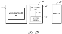
- FIGURE 1B is a schematic view of the input device 22, the computer 26, and the monitor 28 from Figure 1A .
- the computer 26 provides a general-purpose digital computing environment that may be used in combination with the input device 22 to implement various aspects of the present invention.
- the computer 26 includes a processing unit 44, a system memory 46, and a system bus 48.
- the system bus 48 couples various system components including the system memory 46 to the processing unit 44.
- the system bus 48 may be any of several types of bus structures including a memory bus or memory controller, a peripheral bus, and a local bus using any of a variety of bus architectures.
- the system memory 46 includes read only memory (ROM) and/or random access memory (RAM).
- a basic input/output system containing the basic routines that help to transfer information between elements within the computer 26, such as during start-up, can be stored in the ROM of the system memory 46.
- the computer 26 also includes one or more of a hard disk drive, a magnetic disk drive, or an optical disk drive.
- the drives and their associated computer-readable media provide nonvolatile storage of computer readable instructions, data structures, program modules, and other data for the computer 26. It will be appreciated by those skilled in the art that other types of computer readable media that may store data that is accessible by the computer 26, such as magnetic cassettes, flash memory cards, digital video disks, random access memories (RAMs), read only memories (ROMs), and the like, may also be used in the exemplary operating environment.
- software modules may be stored on one or more of the hard disk drive, the magnetic disk, the optical disk, the ROM, or the RAM.
- the software modules can include an operating system, one or more application programs, other program modules, and program data.
- the software modules can include an application program configured to receive user instructions input to the input device 22 for manipulating an image displayed on the monitor 28.
- the software modules receive the user instructions from the microcontroller 49.
- the image can be a digital image being viewed by a pathologist.
- the input device 22 is configured to receive input generated by the user via the one or more rotatable control knobs 36, 38, 40.
- the plurality of rotatable control knobs includes three control knobs 36, 38, 40.
- the housing 34 can include the microcontroller (MCU) 49.
- the microcontroller 49 can be disposed in the one or more rotatable control knobs 36, 38, 40.
- the microcontroller 49 contains one or more CPUs along with memory and programmable general-purpose input/output (GPIO).
- GPIO pins are connected to the one or more rotatable control knobs 36, 38, 40 to define an input/output map.
- the GPIO pins can be further connected to the touch pad 42.
- firmware including operating instructions can be flashed to the microcontroller 49 as known to a person having ordinary skill in the art.
- the firmware of the microcontroller 49 converts the input received from the user or pathologist via the one or more rotatable control knobs 36, 38, 40 and/or touch pad 42 to commands suitable for transmission to the computer 26.
- the input device 22 and/or the other peripheral devices connect to the computer 26 through an interface.
- the data or commands from the microcontroller 49 are transmitted to the computer 26 using the Universal Serial Bus (USB) standard.
- USB Universal Serial Bus
- the input device 22 can use other protocols known to a person having ordinary skill in the art for transmitting data or commands between peripherals and the computer 26.
- Other exemplary interfaces include serial ports, parallel ports, and game ports.
- the input device 22 and/or the other peripheral devices may be coupled directly to the system bus via an appropriate interface (not shown).
- the monitor 28 or other type of display device with a display screen is also connected to the system bus 48 via an interface, such as a video adapter.
- the monitor 28 can display information for the user or pathologist, such as one or more digital images.
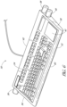
- FIGURE 6 is a front perspective view of a computer keyboard 50 according to another preferred embodiment of the present invention.
- the keyboard 50 is configured to allow the user or pathologist to manipulate the image displayed by a user interface (UI) of the computer 26 (see Figure 1A ).
- UI user interface
- the keyboard 50 is similar to the input device 22 except the keyboard 50 includes a panel of keys 54.
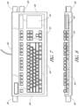
- FIGURE 7 is a top plan view of the keyboard 50 from Figure 6 .
- FIGURE 8 is a front view of the keyboard 50 of Figure 7 .
- the keyboard 50 includes a housing 52.
- the housing 52 has a rectangular shape.
- the shape of the housing 52 of the keyboard 50 is not limited to a rectangular shape and instead can have any other desirable shape.
- the housing 52 has a first end 56 and a second end 58.
- the direction "lateral" defines the general directions from the first end 56 to the second end 58 and from the second end 58 to the first end 56.
- a front side 60 and a back side 62 of the keyboard 50 connect the first end 56 to the second end 58.
- the front side 60 is adjacent to the user during normal use, and the back side 62 is distal from the user during normal use.
- the panel of keys 54 is disposed between the first end 56, the second end 58, the front side 60, and the back side 62 of the housing 52.
- the panel of keys 54 are configured for the user or pathologist to operate the computer 26.
- the keyboard 50 further includes a touch pad 42 in combination with the one or more rotatable control knobs 36, 38, 40.
- the touch pad 42 is employed by the user or pathologist for annotation or drawing and slide selection.
- the touch pad 42 can be any appropriate shape, such as a square, rectangular, diamond, circular, cross, or oval.
- the keyboard 50 need not include the touch pad 42.
- the mouse 32 is employed instead of the touch pad 42 for annotation or drawing and slide selection.
- FIGURE 9 is a right side view of the keyboard 50 of Figure 7 .
- FIGURE 10 is a left side view of the keyboard 50 of Figure 7 .
- the keyboard 50 can be operatively connected to the computer 26 ( Figure 1A ) and is configured for panning and zooming an image in multiple axes relative to the display screen of the monitor 28. In this way, the keyboard 50 is configured for two-handed functionality with the one or more rotatable control knobs 36, 38, 40.
- At least one of the rotatable control knobs 36, 38, 40 is disposed on each of the first and second ends 56, 58 of the housing 52.
- the housing 52 includes two rotatable control knobs on the second end 58 of the housing 52.
- the invention is not limited to the illustrated embodiments.
- the housing 52 includes two rotatable control knobs on the first end 56 of the housing 52.
- the housing 52 includes a first rotatable control knob 36 supported by the housing 52.
- the first rotatable control knob 36 is configured for the user or pathologist to perform a first manipulation of the image on the UI.
- Another one of the rotatable control knobs 36, 38, 40 is configured for the user to perform a second manipulation of the image on the display or UI.
- the housing 52 includes a second rotatable control knob 38 supported by the housing 52.
- the second rotatable control knob 38 is configured for the user or pathologist to perform a second manipulation of the image on the UI.
- the keyboard 50 comprises a third rotatable control knob 40 disposed on either the first end 56 or the second end 58 of the housing 52.
- the third rotatable control knob 40 is disposed on the second end 58 of the housing 52. In certain embodiments, the third rotatable control knob 40 is configured for the user or pathologist to perform a third manipulation of the image on the UI.
- the first manipulation is zooming of the image and the second manipulation is panning. In certain embodiments, the first manipulation is zooming of the image, the second manipulation is panning up/down of the image, and the third manipulation is panning left/right of the image. In certain embodiments, the first manipulation, the second manipulation, and the third manipulation can be performed simultaneously by the user.
- both rotatable control knobs can be used simultaneously on either side of the keyboard 50 for zooming and/or panning control. In this way, zooming and panning control is separately controlled by individual hands of the user.
- the third one of the rotatable control knobs 36, 38, 40 is configured for panning control in a different direction.
- the second one of the rotatable control knobs 36, 38, 40 is configured for panning control of the image along a first axis and the third one of the rotatable control knobs 36, 38, 40 is configured for panning control of the image along a second axis perpendicular to the first axis.
- each of the rotatable control knobs 38, 40 on the second end 58 are for panning control in either the up/down or left/right directions.
- the keyboard 50 can include the microcontroller (MCU) 49 as described above.
- the microcontroller 49 contains one or more CPUs along with memory and programmable general-purpose input/output (GPIO).
- the microcontroller 49 converts the input received from the user or pathologist to commands suitable for transmission to the computer 26.
- the microcontroller 49 can receive a plurality of position and/or zoom signals from at least the first, second, and third rotatable control knobs 36, 38, 40 and convert the position and/or zoom signals to a plurality of instructions for the computer 26 to manipulate the image displayed by the UI.
- the keyboard 50 include the touch pad 42.
- the microcontroller 49 converts the input received from the user or pathologist via the one or more rotatable control knobs 36, 38, 40 and/or touch pad 42 to commands suitable for transmission to the computer 26.
- the keyboard 50 connects to the computer system 24 through an interface. In certain embodiments, the keyboard 50 connects to the computer system 24 via a wired or wireless connection. In certain embodiments, the keyboard 50 can be directly connected to a wired or wireless network without being connected to the computer system 24. In certain embodiments, the network includes one or more servers.
- the data or commands from the microcontroller 49 are transmitted to the computer 26 using the Universal Serial Bus (USB) standard.
- USB Universal Serial Bus
- the keyboard 50 can use other protocols known to a person having ordinary skill in the art for transmitting data or commands between peripherals and the computer 26.
- Other exemplary interfaces include serial ports, parallel ports, and game ports.
- the keyboard 50 and/or the other peripheral devices may be coupled directly to the system bus via an appropriate interface (not shown).
Landscapes
- Engineering & Computer Science (AREA)
- General Engineering & Computer Science (AREA)
- Theoretical Computer Science (AREA)
- Human Computer Interaction (AREA)
- Physics & Mathematics (AREA)
- General Physics & Mathematics (AREA)
- Microscoopes, Condenser (AREA)
- Position Input By Displaying (AREA)
Claims (10)
- Eingabevorrichtung (22, 50), die dafür konfiguriert ist, es einem Benutzer zu ermöglichen, ein von einer Benutzeroberfläche (UI) eines Computers angezeigtes Bild zu bearbeiten, umfassend:ein Gehäuse (34, 52), wobei das Gehäuse ein erstes Ende (56) und ein zweites Ende (58), und eine Vorderseite (60) und eine Rückseite (62), die das erste Ende (56) und das zweite Ende (58) verbinden, umfasst; gekennzeichnet durcheinen ersten drehbaren Steuerknopf (36, 38, 40), der von dem Gehäuse getragen wird, wobei der erste drehbare Steuerknopf dafür konfiguriert ist, dass der Benutzer eine erste Bearbeitung des Bildes auf der UI durchführt; undeinen zweiten drehbaren Steuerknopf (36, 38, 40), der von dem Gehäuse getragen wird, wobei der zweite drehbare Steuerknopf dafür konfiguriert ist, dass der Benutzer eine zweite Bearbeitung des Bildes auf der UI durchführt, wobei die zweite Bearbeitung von der ersten Bearbeitung unterschiedlich ist,einen dritten drehbaren Steuerknopf (36, 38, 40), der an entweder dem ersten Ende oder dem zweiten Ende des Gehäuses angeordnet ist, wobei der dritte drehbare Steuerknopf dafür konfiguriert ist, dass der Benutzer eine dritte Bearbeitung des Bildes auf der UI durchführt;einen vierten drehbaren Steuerknopf, der eine Steuerung eines Fokus-Stacking des von der UI angezeigten Bildes bereitstellt;wobei die erste Bearbeitung eine von Vergrößern oder Schwenken des Bildes ist und die zweite Bearbeitung die andere von Vergrößern oder Schwenken des Bildes ist, undwobei der erste drehbare Steuerknopf an dem ersten Ende des Gehäuses angeordnet ist und der zweite drehbare Steuerknopf an dem zweiten Ende des Gehäuses angeordnet ist.
- Eingabevorrichtung nach Anspruch 1, wobei die Eingabevorrichtung als eine Tastatur konfiguriert ist.
- Eingabevorrichtung nach Anspruch 2, wobei die Eingabevorrichtung weiter ein Tastenfeld (54) umfasst, das zwischen dem ersten Ende und dem zweiten Ende angeordnet ist.
- Eingabevorrichtung nach Anspruch 1, wobei die Eingabevorrichtung als ein Monitor (28) konfiguriert ist, wobei der Monitor zum Anzeigen des Bildes konfiguriert ist.
- Eingabevorrichtung nach Anspruch 1, wobei die Eingabevorrichtung als der Computer (26) konfiguriert ist.
- Eingabevorrichtung nach Anspruch 1, weiter umfassend einen Mikrocontroller (49), wobei der Mikrocontroller dafür konfiguriert ist, eine Vielzahl von Positions- und/oder Vergrößerungssignalen von zumindest dem ersten und dem zweiten drehbaren Steuerknopf zu empfangen und die Positions- und/oder Vergrößerungssignale in eine Vielzahl von Anweisungen für den Computer zum Bearbeiten des von der UI angezeigten Bildes umzuwandeln.
- Eingabevorrichtung nach Anspruch 1, weiter umfassend ein Berührungsfeld (42).
- Eingabevorrichtung nach Anspruch 1, wobei mindestens zwei der ersten Bearbeitung, der zweiten Bearbeitung und der dritten Bearbeitung von dem Benutzer gleichzeitig durchgeführt werden können.
- Eingabevorrichtung nach Anspruch 1, wobei das Bild ein gescanntes digitales Bild ist.
- Eingabevorrichtung nach Anspruch 9, wobei das gescannte digitale Bild eine Gewebeprobe für eine Biopsie darstellt.
Applications Claiming Priority (2)
| Application Number | Priority Date | Filing Date | Title |
|---|---|---|---|
| US202063129860P | 2020-12-23 | 2020-12-23 | |
| PCT/US2021/063319 WO2022140115A1 (en) | 2020-12-23 | 2021-12-14 | Input device with rotatable control knobs |
Publications (2)
| Publication Number | Publication Date |
|---|---|
| EP4232887A1 EP4232887A1 (de) | 2023-08-30 |
| EP4232887B1 true EP4232887B1 (de) | 2025-03-26 |
Family
ID=79731140
Family Applications (1)
| Application Number | Title | Priority Date | Filing Date |
|---|---|---|---|
| EP21841102.3A Active EP4232887B1 (de) | 2020-12-23 | 2021-12-14 | Eingabevorrichtung mit drehbaren betätigungsknöpfen |
Country Status (4)
| Country | Link |
|---|---|
| US (1) | US12346509B2 (de) |
| EP (1) | EP4232887B1 (de) |
| CN (1) | CN116635814A (de) |
| WO (1) | WO2022140115A1 (de) |
Families Citing this family (1)
| Publication number | Priority date | Publication date | Assignee | Title |
|---|---|---|---|---|
| WO2025117406A1 (en) * | 2023-11-30 | 2025-06-05 | Leica Biosystems Imaging, Inc. | Input device with rotatable control knobs |
Citations (1)
| Publication number | Priority date | Publication date | Assignee | Title |
|---|---|---|---|---|
| EP2613239A1 (de) * | 2012-01-05 | 2013-07-10 | SONOTEC Dr. zur Horst-Meyer und Münch OHG | Mobile Einrichtung zur computergestützten Ein- und Ausgabe von Daten mit einer integrierten Bildschirmausgabeeinheit und Verfahren zur Visualisierung ihrer Bedienung |
Family Cites Families (26)
| Publication number | Priority date | Publication date | Assignee | Title |
|---|---|---|---|---|
| US7075513B2 (en) * | 2001-09-04 | 2006-07-11 | Nokia Corporation | Zooming and panning content on a display screen |
| DE10235656A1 (de) * | 2002-08-02 | 2004-02-19 | Leica Microsystems Heidelberg Gmbh | Verfahren und Anordnung zur Mikroskopie |
| DE10314752A1 (de) * | 2003-04-01 | 2004-10-14 | Leica Microsystems Wetzlar Gmbh | Bedienknopf für optische Systeme |
| US7441193B1 (en) * | 2003-10-07 | 2008-10-21 | Euphonix, Inc. | Adaptable and widely applicable control surface |
| EP1676116B8 (de) * | 2003-10-21 | 2012-07-04 | Leica Microsystems CMS GmbH | Verfahren zur automatischen erzeugung von laser-schnittlinien in der laser-mikrodissektion |
| US7315414B2 (en) * | 2004-03-31 | 2008-01-01 | Swift Instruments, Inc. | Microscope with adjustable stage |
| US7518745B2 (en) * | 2005-09-28 | 2009-04-14 | Xerox Corporation | Imaging system with haptic interface |
| US8244021B2 (en) * | 2006-12-20 | 2012-08-14 | Ventana Medical Systems, Inc. | Quantitative, multispectral image analysis of tissue specimens stained with quantum dots |
| DE102007045669A1 (de) * | 2007-09-25 | 2009-04-02 | Carl Zeiss Microimaging Gmbh | Bedieneinrichtung für den Fokussiertrieb eines Mikroskops |
| US20090091566A1 (en) * | 2007-10-05 | 2009-04-09 | Turney Stephen G | System and methods for thick specimen imaging using a microscope based tissue sectioning device |
| AU2008343383B2 (en) * | 2007-12-27 | 2013-08-29 | Cytyc Corporation | Apparatus for single-handed control of microscope functions |
| WO2010102113A2 (en) * | 2009-03-04 | 2010-09-10 | Mayo Foundation For Medical Education And Research | Computer input device |
| JP5306088B2 (ja) * | 2009-07-14 | 2013-10-02 | オリンパス株式会社 | 顕微鏡システム |
| KR20140063993A (ko) * | 2012-11-19 | 2014-05-28 | 삼성메디슨 주식회사 | 의료 영상 생성 장치 및 방법 |
| DE102013007000A1 (de) * | 2013-04-19 | 2014-10-23 | Carl Zeiss Microscopy Gmbh | Steuergerät und Verfahren zur Steuerung eines motorisierten Digitalmikroskops |
| DE102013109481A1 (de) * | 2013-08-30 | 2015-03-05 | Firma Leica Microsystems CMS GmbH | Lasermikrodissektionssystem und Lasermikrodissektionsverfahren |
| CN107076980A (zh) * | 2014-08-18 | 2017-08-18 | 维斯科技有限公司 | 用于大视场显微扫描中嵌入图像的系统和方法 |
| JP6643071B2 (ja) * | 2015-12-10 | 2020-02-12 | キヤノン株式会社 | 顕微鏡システム |
| US10203491B2 (en) * | 2016-08-01 | 2019-02-12 | Verily Life Sciences Llc | Pathology data capture |
| WO2018042413A1 (en) * | 2016-08-28 | 2018-03-08 | Siegel Gabriel | A system for histological examination of tissue specimens |
| US20180164996A1 (en) * | 2016-12-12 | 2018-06-14 | Logitech Europe S.A. | Contextually-based functional assignment for a user-manipulable element on an input device |
| JP2018112573A (ja) * | 2017-01-06 | 2018-07-19 | オリンパス株式会社 | 顕微鏡システム |
| JP6947841B2 (ja) * | 2017-06-13 | 2021-10-13 | グーグル エルエルシーGoogle LLC | 病理学用の拡張現実顕微鏡 |
| US20190107895A1 (en) * | 2017-10-11 | 2019-04-11 | Daniel James STEINMAN | Wireless dial universal remote control device |
| EP3844771A1 (de) * | 2018-08-31 | 2021-07-07 | Ventana Medical Systems, Inc. | Kontextuell adaptive digitale pathologieschnittstelle |
| CN111831128B (zh) * | 2020-07-01 | 2021-11-09 | 黑龙江数米科技有限公司 | 扩展键盘 |
-
2021
- 2021-12-14 WO PCT/US2021/063319 patent/WO2022140115A1/en not_active Ceased
- 2021-12-14 EP EP21841102.3A patent/EP4232887B1/de active Active
- 2021-12-14 CN CN202180085057.4A patent/CN116635814A/zh active Pending
-
2023
- 2023-05-31 US US18/203,808 patent/US12346509B2/en active Active
Patent Citations (1)
| Publication number | Priority date | Publication date | Assignee | Title |
|---|---|---|---|---|
| EP2613239A1 (de) * | 2012-01-05 | 2013-07-10 | SONOTEC Dr. zur Horst-Meyer und Münch OHG | Mobile Einrichtung zur computergestützten Ein- und Ausgabe von Daten mit einer integrierten Bildschirmausgabeeinheit und Verfahren zur Visualisierung ihrer Bedienung |
Also Published As
| Publication number | Publication date |
|---|---|
| US12346509B2 (en) | 2025-07-01 |
| WO2022140115A1 (en) | 2022-06-30 |
| CN116635814A (zh) | 2023-08-22 |
| US20230305649A1 (en) | 2023-09-28 |
| EP4232887A1 (de) | 2023-08-30 |
Similar Documents
| Publication | Publication Date | Title |
|---|---|---|
| Tominski et al. | Interactive lenses for visualization: An extended survey | |
| US7620915B2 (en) | Electronic document editing employing multiple cursors | |
| EP1585015B1 (de) | Benutzerschnittstellenvorrichtung | |
| Wu et al. | Multi-finger and whole hand gestural interaction techniques for multi-user tabletop displays | |
| EP2616903B1 (de) | Steuerungskonfiguration für ein digitalbildsystem | |
| US5936612A (en) | Computer input device and method for 3-D direct manipulation of graphic objects | |
| EP2473928B1 (de) | Digitales pathologiesystem | |
| JP5469090B2 (ja) | 顕微鏡の機能を片手でコントロールするための装置 | |
| EP1569082A2 (de) | Multimodale Navigation für graphische Benutzerschnittstelle verwendendes Rechnersystem | |
| EP1118930A2 (de) | Einhändige Betätigung eines tragbaren Rechners | |
| US12346509B2 (en) | Input device with rotatable control knobs | |
| WO2020033468A1 (en) | Feedback input apparatus and method for use thereof | |
| US10018823B2 (en) | Force-feedback control device and method for digital microscope | |
| US8170698B1 (en) | Virtual robotic controller system with special application to robotic microscopy structure and methodology | |
| US8896620B2 (en) | Computer input device | |
| EP1586970A1 (de) | Benutzerschnittstellenvorrichtung | |
| Geisler et al. | Fovea-tablett®: A new paradigm for the interaction with large screens | |
| Nancel et al. | Precision pointing for ultra-high-resolution wall displays | |
| WO2025117406A1 (en) | Input device with rotatable control knobs | |
| Kopper | Understanding and improving distal pointing interaction | |
| Stefels et al. | Equipment control in a sterile environment using the Gyromouse and a new interface, the user interface (UI) wand | |
| Rogers et al. | A comparative usability assessment of computer input devices for navigating digital whole slide images | |
| Wegner | SimWiz3D-visualising biochemical simulation results | |
| DE202004021400U1 (de) | Benutzerschnittstellenvorrichtung | |
| WO2021094540A1 (en) | Method of determining and displaying an area of interest of a digital microscopic tissue image, input / output system for navigating a patient-specific image record, and work place comprising such input / output system |
Legal Events
| Date | Code | Title | Description |
|---|---|---|---|
| STAA | Information on the status of an ep patent application or granted ep patent |
Free format text: STATUS: UNKNOWN |
|
| STAA | Information on the status of an ep patent application or granted ep patent |
Free format text: STATUS: THE INTERNATIONAL PUBLICATION HAS BEEN MADE |
|
| PUAI | Public reference made under article 153(3) epc to a published international application that has entered the european phase |
Free format text: ORIGINAL CODE: 0009012 |
|
| STAA | Information on the status of an ep patent application or granted ep patent |
Free format text: STATUS: REQUEST FOR EXAMINATION WAS MADE |
|
| 17P | Request for examination filed |
Effective date: 20230524 |
|
| AK | Designated contracting states |
Kind code of ref document: A1 Designated state(s): AL AT BE BG CH CY CZ DE DK EE ES FI FR GB GR HR HU IE IS IT LI LT LU LV MC MK MT NL NO PL PT RO RS SE SI SK SM TR |
|
| DAV | Request for validation of the european patent (deleted) | ||
| DAX | Request for extension of the european patent (deleted) | ||
| STAA | Information on the status of an ep patent application or granted ep patent |
Free format text: STATUS: EXAMINATION IS IN PROGRESS |
|
| 17Q | First examination report despatched |
Effective date: 20240531 |
|
| GRAP | Despatch of communication of intention to grant a patent |
Free format text: ORIGINAL CODE: EPIDOSNIGR1 |
|
| STAA | Information on the status of an ep patent application or granted ep patent |
Free format text: STATUS: GRANT OF PATENT IS INTENDED |
|
| RIC1 | Information provided on ipc code assigned before grant |
Ipc: G06F 3/0485 20220101ALI20241024BHEP Ipc: G06F 3/04845 20220101ALI20241024BHEP Ipc: G06F 3/0362 20130101ALI20241024BHEP Ipc: G06F 3/02 20060101AFI20241024BHEP |
|
| INTG | Intention to grant announced |
Effective date: 20241115 |
|
| GRAS | Grant fee paid |
Free format text: ORIGINAL CODE: EPIDOSNIGR3 |
|
| GRAA | (expected) grant |
Free format text: ORIGINAL CODE: 0009210 |
|
| STAA | Information on the status of an ep patent application or granted ep patent |
Free format text: STATUS: THE PATENT HAS BEEN GRANTED |
|
| P01 | Opt-out of the competence of the unified patent court (upc) registered |
Free format text: CASE NUMBER: APP_5632/2025 Effective date: 20250203 |
|
| AK | Designated contracting states |
Kind code of ref document: B1 Designated state(s): AL AT BE BG CH CY CZ DE DK EE ES FI FR GB GR HR HU IE IS IT LI LT LU LV MC MK MT NL NO PL PT RO RS SE SI SK SM TR |
|
| REG | Reference to a national code |
Ref country code: GB Ref legal event code: FG4D |
|
| REG | Reference to a national code |
Ref country code: CH Ref legal event code: EP |
|
| REG | Reference to a national code |
Ref country code: DE Ref legal event code: R096 Ref document number: 602021028269 Country of ref document: DE |
|
| REG | Reference to a national code |
Ref country code: IE Ref legal event code: FG4D |
|
| PG25 | Lapsed in a contracting state [announced via postgrant information from national office to epo] |
Ref country code: RS Free format text: LAPSE BECAUSE OF FAILURE TO SUBMIT A TRANSLATION OF THE DESCRIPTION OR TO PAY THE FEE WITHIN THE PRESCRIBED TIME-LIMIT Effective date: 20250626 |
|
| PG25 | Lapsed in a contracting state [announced via postgrant information from national office to epo] |
Ref country code: FI Free format text: LAPSE BECAUSE OF FAILURE TO SUBMIT A TRANSLATION OF THE DESCRIPTION OR TO PAY THE FEE WITHIN THE PRESCRIBED TIME-LIMIT Effective date: 20250326 |
|
| REG | Reference to a national code |
Ref country code: LT Ref legal event code: MG9D |
|
| PG25 | Lapsed in a contracting state [announced via postgrant information from national office to epo] |
Ref country code: NO Free format text: LAPSE BECAUSE OF FAILURE TO SUBMIT A TRANSLATION OF THE DESCRIPTION OR TO PAY THE FEE WITHIN THE PRESCRIBED TIME-LIMIT Effective date: 20250626 |
|
| PG25 | Lapsed in a contracting state [announced via postgrant information from national office to epo] |
Ref country code: HR Free format text: LAPSE BECAUSE OF FAILURE TO SUBMIT A TRANSLATION OF THE DESCRIPTION OR TO PAY THE FEE WITHIN THE PRESCRIBED TIME-LIMIT Effective date: 20250326 |
|
| PG25 | Lapsed in a contracting state [announced via postgrant information from national office to epo] |
Ref country code: LV Free format text: LAPSE BECAUSE OF FAILURE TO SUBMIT A TRANSLATION OF THE DESCRIPTION OR TO PAY THE FEE WITHIN THE PRESCRIBED TIME-LIMIT Effective date: 20250326 |
|
| PG25 | Lapsed in a contracting state [announced via postgrant information from national office to epo] |
Ref country code: BG Free format text: LAPSE BECAUSE OF FAILURE TO SUBMIT A TRANSLATION OF THE DESCRIPTION OR TO PAY THE FEE WITHIN THE PRESCRIBED TIME-LIMIT Effective date: 20250326 Ref country code: GR Free format text: LAPSE BECAUSE OF FAILURE TO SUBMIT A TRANSLATION OF THE DESCRIPTION OR TO PAY THE FEE WITHIN THE PRESCRIBED TIME-LIMIT Effective date: 20250627 |
|
| REG | Reference to a national code |
Ref country code: NL Ref legal event code: MP Effective date: 20250326 |
|
| PG25 | Lapsed in a contracting state [announced via postgrant information from national office to epo] |
Ref country code: NL Free format text: LAPSE BECAUSE OF FAILURE TO SUBMIT A TRANSLATION OF THE DESCRIPTION OR TO PAY THE FEE WITHIN THE PRESCRIBED TIME-LIMIT Effective date: 20250326 |
|
| PG25 | Lapsed in a contracting state [announced via postgrant information from national office to epo] |
Ref country code: SE Free format text: LAPSE BECAUSE OF FAILURE TO SUBMIT A TRANSLATION OF THE DESCRIPTION OR TO PAY THE FEE WITHIN THE PRESCRIBED TIME-LIMIT Effective date: 20250326 |
|
| REG | Reference to a national code |
Ref country code: AT Ref legal event code: MK05 Ref document number: 1779564 Country of ref document: AT Kind code of ref document: T Effective date: 20250326 |
|
| PG25 | Lapsed in a contracting state [announced via postgrant information from national office to epo] |
Ref country code: SM Free format text: LAPSE BECAUSE OF FAILURE TO SUBMIT A TRANSLATION OF THE DESCRIPTION OR TO PAY THE FEE WITHIN THE PRESCRIBED TIME-LIMIT Effective date: 20250326 |
|
| PG25 | Lapsed in a contracting state [announced via postgrant information from national office to epo] |
Ref country code: ES Free format text: LAPSE BECAUSE OF FAILURE TO SUBMIT A TRANSLATION OF THE DESCRIPTION OR TO PAY THE FEE WITHIN THE PRESCRIBED TIME-LIMIT Effective date: 20250326 Ref country code: PT Free format text: LAPSE BECAUSE OF FAILURE TO SUBMIT A TRANSLATION OF THE DESCRIPTION OR TO PAY THE FEE WITHIN THE PRESCRIBED TIME-LIMIT Effective date: 20250728 |
|
| PG25 | Lapsed in a contracting state [announced via postgrant information from national office to epo] |
Ref country code: PL Free format text: LAPSE BECAUSE OF FAILURE TO SUBMIT A TRANSLATION OF THE DESCRIPTION OR TO PAY THE FEE WITHIN THE PRESCRIBED TIME-LIMIT Effective date: 20250326 Ref country code: IT Free format text: LAPSE BECAUSE OF FAILURE TO SUBMIT A TRANSLATION OF THE DESCRIPTION OR TO PAY THE FEE WITHIN THE PRESCRIBED TIME-LIMIT Effective date: 20250326 |
|
| PG25 | Lapsed in a contracting state [announced via postgrant information from national office to epo] |
Ref country code: AT Free format text: LAPSE BECAUSE OF FAILURE TO SUBMIT A TRANSLATION OF THE DESCRIPTION OR TO PAY THE FEE WITHIN THE PRESCRIBED TIME-LIMIT Effective date: 20250326 |
|
| PG25 | Lapsed in a contracting state [announced via postgrant information from national office to epo] |
Ref country code: EE Free format text: LAPSE BECAUSE OF FAILURE TO SUBMIT A TRANSLATION OF THE DESCRIPTION OR TO PAY THE FEE WITHIN THE PRESCRIBED TIME-LIMIT Effective date: 20250326 |
|
| PG25 | Lapsed in a contracting state [announced via postgrant information from national office to epo] |
Ref country code: RO Free format text: LAPSE BECAUSE OF FAILURE TO SUBMIT A TRANSLATION OF THE DESCRIPTION OR TO PAY THE FEE WITHIN THE PRESCRIBED TIME-LIMIT Effective date: 20250326 |
|
| PG25 | Lapsed in a contracting state [announced via postgrant information from national office to epo] |
Ref country code: SK Free format text: LAPSE BECAUSE OF FAILURE TO SUBMIT A TRANSLATION OF THE DESCRIPTION OR TO PAY THE FEE WITHIN THE PRESCRIBED TIME-LIMIT Effective date: 20250326 |
|
| PG25 | Lapsed in a contracting state [announced via postgrant information from national office to epo] |
Ref country code: IS Free format text: LAPSE BECAUSE OF FAILURE TO SUBMIT A TRANSLATION OF THE DESCRIPTION OR TO PAY THE FEE WITHIN THE PRESCRIBED TIME-LIMIT Effective date: 20250726 |