EP4232741B1 - Verbesserte isolierte kupplung - Google Patents
Verbesserte isolierte kupplung Download PDFInfo
- Publication number
- EP4232741B1 EP4232741B1 EP22783068.4A EP22783068A EP4232741B1 EP 4232741 B1 EP4232741 B1 EP 4232741B1 EP 22783068 A EP22783068 A EP 22783068A EP 4232741 B1 EP4232741 B1 EP 4232741B1
- Authority
- EP
- European Patent Office
- Prior art keywords
- coupling
- seal
- liquefied gas
- lock position
- warm
- Prior art date
- Legal status (The legal status is an assumption and is not a legal conclusion. Google has not performed a legal analysis and makes no representation as to the accuracy of the status listed.)
- Active
Links
Images


Classifications
-
- F—MECHANICAL ENGINEERING; LIGHTING; HEATING; WEAPONS; BLASTING
- F16—ENGINEERING ELEMENTS AND UNITS; GENERAL MEASURES FOR PRODUCING AND MAINTAINING EFFECTIVE FUNCTIONING OF MACHINES OR INSTALLATIONS; THERMAL INSULATION IN GENERAL
- F16L—PIPES; JOINTS OR FITTINGS FOR PIPES; SUPPORTS FOR PIPES, CABLES OR PROTECTIVE TUBING; MEANS FOR THERMAL INSULATION IN GENERAL
- F16L59/00—Thermal insulation in general
- F16L59/14—Arrangements for the insulation of pipes or pipe systems
- F16L59/141—Arrangements for the insulation of pipes or pipe systems in which the temperature of the medium is below that of the ambient temperature
-
- F—MECHANICAL ENGINEERING; LIGHTING; HEATING; WEAPONS; BLASTING
- F16—ENGINEERING ELEMENTS AND UNITS; GENERAL MEASURES FOR PRODUCING AND MAINTAINING EFFECTIVE FUNCTIONING OF MACHINES OR INSTALLATIONS; THERMAL INSULATION IN GENERAL
- F16L—PIPES; JOINTS OR FITTINGS FOR PIPES; SUPPORTS FOR PIPES, CABLES OR PROTECTIVE TUBING; MEANS FOR THERMAL INSULATION IN GENERAL
- F16L37/00—Couplings of the quick-acting type
- F16L37/28—Couplings of the quick-acting type with fluid cut-off means
- F16L37/30—Couplings of the quick-acting type with fluid cut-off means with fluid cut-off means in each of two pipe-end fittings
- F16L37/36—Couplings of the quick-acting type with fluid cut-off means with fluid cut-off means in each of two pipe-end fittings with two lift valves being actuated to initiate the flow through the coupling after the two coupling parts are locked against withdrawal
-
- F—MECHANICAL ENGINEERING; LIGHTING; HEATING; WEAPONS; BLASTING
- F16—ENGINEERING ELEMENTS AND UNITS; GENERAL MEASURES FOR PRODUCING AND MAINTAINING EFFECTIVE FUNCTIONING OF MACHINES OR INSTALLATIONS; THERMAL INSULATION IN GENERAL
- F16L—PIPES; JOINTS OR FITTINGS FOR PIPES; SUPPORTS FOR PIPES, CABLES OR PROTECTIVE TUBING; MEANS FOR THERMAL INSULATION IN GENERAL
- F16L39/00—Joints or fittings for double-walled or multi-channel pipes or pipe assemblies
- F16L39/005—Joints or fittings for double-walled or multi-channel pipes or pipe assemblies for concentric pipes
-
- F—MECHANICAL ENGINEERING; LIGHTING; HEATING; WEAPONS; BLASTING
- F16—ENGINEERING ELEMENTS AND UNITS; GENERAL MEASURES FOR PRODUCING AND MAINTAINING EFFECTIVE FUNCTIONING OF MACHINES OR INSTALLATIONS; THERMAL INSULATION IN GENERAL
- F16L—PIPES; JOINTS OR FITTINGS FOR PIPES; SUPPORTS FOR PIPES, CABLES OR PROTECTIVE TUBING; MEANS FOR THERMAL INSULATION IN GENERAL
- F16L59/00—Thermal insulation in general
- F16L59/06—Arrangements using an air layer or vacuum
- F16L59/065—Arrangements using an air layer or vacuum using vacuum
-
- F—MECHANICAL ENGINEERING; LIGHTING; HEATING; WEAPONS; BLASTING
- F16—ENGINEERING ELEMENTS AND UNITS; GENERAL MEASURES FOR PRODUCING AND MAINTAINING EFFECTIVE FUNCTIONING OF MACHINES OR INSTALLATIONS; THERMAL INSULATION IN GENERAL
- F16L—PIPES; JOINTS OR FITTINGS FOR PIPES; SUPPORTS FOR PIPES, CABLES OR PROTECTIVE TUBING; MEANS FOR THERMAL INSULATION IN GENERAL
- F16L2201/00—Special arrangements for pipe couplings
- F16L2201/20—Safety or protective couplings
-
- F—MECHANICAL ENGINEERING; LIGHTING; HEATING; WEAPONS; BLASTING
- F16—ENGINEERING ELEMENTS AND UNITS; GENERAL MEASURES FOR PRODUCING AND MAINTAINING EFFECTIVE FUNCTIONING OF MACHINES OR INSTALLATIONS; THERMAL INSULATION IN GENERAL
- F16L—PIPES; JOINTS OR FITTINGS FOR PIPES; SUPPORTS FOR PIPES, CABLES OR PROTECTIVE TUBING; MEANS FOR THERMAL INSULATION IN GENERAL
- F16L59/00—Thermal insulation in general
- F16L59/14—Arrangements for the insulation of pipes or pipe systems
- F16L59/16—Arrangements specially adapted to local requirements at flanges, junctions, valves or the like
- F16L59/18—Arrangements specially adapted to local requirements at flanges, junctions, valves or the like adapted for joints
- F16L59/182—Joints with sleeve or socket
Definitions
- the present invention relates to an improved coupling for transfer of liquefied gas enabling secure purging of the volume between a first and second part of the coupling.
- the warm seal is engaged such that, in the second lock position, the warm seal is located between the purge opening and the connection point, and the warm seal is engaged such that the warm seal is located between the purge opening and the connection point.
- the warm and cold seals are annular seals.
- the locking device comprises an actuatable lock preventing the coupling from passing the first lock position without actuation of the lock.
- the entire coupling may comprise only one valve at each side, the reason for this is that the warm and cold seal creates additional safety barriers. Further, by introducing the first lock position disabling complete disconnection of the coupling without a soft or hard stop in the purging position, leakage in any one of the valve arrangements may be detected via the purge opening before complete disconnection.
- the emergency release device is separate from the locking device such that upon emergency release at least one part of the second part is separated and instead attached to the first part after separation.
- the first part comprises a first valve arrangement with a valve comprising a stem and a valve head
- the second part comprise a second valve arrangement with a valve comprising a stem and a valve head, wherein one of said valves is spring-loaded and the other of said valves is arranged in a fixed position in the valve arrangement.
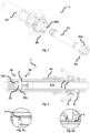
- Figure 1 illustrates one embodiment of a coupling 1 wherein the first part 11 and second part 12 are shown.
- the first part 11 is a male part and the second part 12 is a female part, wherein the first part is adapted for insertion into the second part.
- the first part 11 is mostly installed on a vehicle, fuel tank, bunker vessel, or any other suitable unit for receiving the liquefied gas.
- the second part 12 is most likely installed on a fuel station, transport unit, rail car, tank truck, or similar unit for dispatching the liquefied gas.
- a fuel station transport unit
- rail car rail car
- tank truck or similar unit for dispatching the liquefied gas.
- other arrangements are also possible within the scope of the solution as described herein.
- Figure 1 further illustrates one embodiment of the solution wherein the coupling 1 is engaged by align rollers 6b1 to the entrances of a cam curves 6a1.
- This solution provides distinctive steps to achieve the first and second lock positions, however it should be noted that other solutions are possible as well.
- the user pulls the locking device button and push the second part 12 being hose unit forward to engage the rollers into the cam curve. Then turn for example 5 to 10 degrees until the locking device will lock into a locking hole.
- the rollers keep second part 12 connected to the first part 11 in the first lock position, also called the purge position.
- a locking pin is locking in the locking hole.
- the first section 6a of the locking device 6 comprises a number of cam curves 6a1 and the second section 6b of the locking device 6 comprises a number of rollers 6b1.
- Each curve 6a1 gets into contact with a roller 6b1 when the sections 6a and 6b of the locking device 6 are in contact with each other.
- the sections 6a and 6b are turned in relation to each other and each roller 6b1 will run in respective cam curve 6a1 until they, and the locking device 6, reach a first lock position.
- This is a purge position and in one embodiment movement out of the first lock position is prevented by an actuator 6e. If actuated, the actuator 6e allows further movement, either towards disconnection or towards the second lock position.
- each roller 6b1 When the sections 6a and 6b is turned further in relation to each other, each roller 6b1 will continue to run in respective cam curve 6a1 until they reach a final stop end position, the second lock position.
- the actuator 6e of the locking device 6 comes into an end position and locks the first part 11 and the second part 12 of the coupling 1 to each other.
- the actuator 6e can for example be a pin on the second section 6b of the locking device 6 getting into cooperation with a hole on the first second 6a of the locking device 6. In other embodiments the movement is restricted in other ways.
- the locking device 6 can have another design and can be forced into the two positions in any way suitable.
- Figure 2 illustrates the coupling 1 and how it has a double wall vacuum insulated, design to avoid condensation of air at the outside and to reduce thermal bridges in the coupling 1.
- the first part 2 of the coupling 1 comprises a valve arrangement 2b comprising a valve element and a valve guide having a valve seat.
- the second part 12 of the coupling 1 also comprises a valve arrangement 3b comprising a valve element and a valve guide having a valve seat.
- the first 11 and second 12 parts each has an elongated form and comprises an internal liquefied gas conduit 11a and 12a for transporting the liquefied gas through the coupling 1 when the parts 11 and 12 are coupled.
- the elongation makes it possible to keep control of the temperature of the liquefied gas passing inside the first part 11 and the second part 12 and to hinder temperature increase of the gas, this is achieved by a volume between the warm 2 and cold 3 seals, see figure 3 .
- the coupling is halted at the first lock position before the coupling is fully connected leaving a space 10a between the valve arrangements 2b, 3b and also a space between the elongated parts of the first and second parts 11, 12.
- the cold seal 3 is not engaged, it is located at a distance from in this embodiment the second part.
- the space 10a is enclosed by the first 11 and second 12 parts and sealed off by the warm seal from the atmosphere.
- figure 2 illustrates the first lock position wherein the first part 11 and the second part 12 are connected, the warm seal 2 is engaged but the cold seal 3 is not engaged. Further, this state allows for a space 10a to be formed in the vicinity of the connection point 10 and between the valve arrangements 2b, 3b.
- Figure 2a illustrates a section of the cold seal 3 and shows how it is not engaged to seal between the first and second parts. Instead, a distance exists between the first and second part opening the volume towards the purge opening 4.
- Figure 2b illustrates a section of the purge opening 4 and the warm seal 2 and how they are arranged in relation to each other in the first lock position.
- Figure 3 illustrates one embodiment of the coupling 1 wherein the first part 11 and the second part 12 of the coupling 1 are fully coupled together in the second lock position permitting the liquefied gas to flow from the conduit 2a of the first part 11 to the conduit 12a of the second part 12 of the coupling 1.
- first part 2 and the second part 3 of the coupling 1 are apart, see for example Figure 1 , at least one valve element is urged into the corresponding valve seat preventing the flow of liquefied gas through the respective liquefied gas conduit 11a and 12a.
- the coupling 1 comprises a second warm seal protecting and sealing the coupling 1 from the atmosphere.
- the second warm seal further seals the purge opening 4 from the atmosphere in the second lock position wherein the purge opening 4 is between the warm seal 2 and the second warm seal.
- Figure 3 further illustrates how the first 11 and second parts 12 seal the liquefied gas conduit from the outside by the cold seal 3 and the warm seal 2.
- the warm seal 2 further seals the purge opening 4 preventing any leakage even if the cold seal 3 would fail.
- Figure 3a illustrates a section of the cold seal 3 and shows how it is engaged in the second lock position to seal between the first and second parts, compare with figure 2a .
- Figure 3b illustrates a section of the purge opening 4 and the warm seal 2 and how they are arranged in relation to each other in the second lock position, compare with figure 2b .
- Figure 4 illustrates one embodiment of the coupling 1 wherein an emergency release device 8 has released the first 11 and second 12 parts from engagement.
- the emergency release device 8 separates the first and second parts at a different position than at usual operation, as illustrated parts of the second part 12 are still connected to the first part 11. This enables that the emergency release device 8 overrides the requirement for the coupling 1 to halt in the first lock position.
- the work of the emergency release device 8 result in an emergency shut down that stops the flow of the liquefied gas.
- the emergency shut down will separate the first part 2 of the coupling 1 from the second part 3 of the coupling 1 to prevent damage of the transfer system.
- the emergency release device 8 comprises elements attached to the second part 12 of the coupling 1. When the coupling 1 is exposed to determined unwanted load or angles, the elements of the emergency release device 8 is activated.
- a wire attached to a release ring is stretched. Then the release ring is pulled off from the clamp construction 8a that then will loose the grip around the flange 8b and be pushed outwards by a conical part of the flange 8b.
- the parts of the second part 12 of the coupling 1 will slide off from the first part 2, away from the locking device 6.
- a stop flange on the outside of the second part 12 of the coupling 1 stops the movement of the release ring along the elongated body of the second part 12 of the coupling 1.
- the valve arrangements 2b and 3b will be closed before the cold seal 4 disengages.
- the emergency release device 8 can have another design and can be forced into action in any way suitable.
- a power emergency release coupling break studs, break pins, or any other suitable solution.
- Figure 5 illustrates one embodiment of a coupling 1 that has been completely released by the emergency release device 8.
- FIGs 6a and 6b illustrate one embodiment of valve arrangements 2b, 3b, wherein figure 6a illustrates the valve arrangements 2b, 3b in the second lock position and figure 6b in the first lock position.
- Each of the valve arrangements 2b, 3b comprises a valve 111, 121, valve seat inserts 112, 122, and springs 114, 124 enabling that each valve arrangement 2b, 3b is brought from a closed to an open state.
- the valve seat 123 of the second part 12 is in the illustrated embodiment spring loaded by the spring 124.
- the valve 121 of the second part is fixed in its position.
- the valve seat 112 of the first part 11 is fixed in its position and the valve 111 of the first part 11 is spring loaded by the spring 114.
- This single poppet valve arrangement helps enable effective purging since no dead space between dual valves is required.
- the internal liquefied gas conduit 11a, 12a is purged before transfer of liquefied gas through the coupling 1.
- the internal liquefied gas conduit 11a, 12a is purged after transfer of liquefied gas through the coupling to remove remnants of for example hydrogen, which may mix with air to create a combustible mixture.
Landscapes
- Engineering & Computer Science (AREA)
- General Engineering & Computer Science (AREA)
- Mechanical Engineering (AREA)
- Quick-Acting Or Multi-Walled Pipe Joints (AREA)
- Filling Or Discharging Of Gas Storage Vessels (AREA)
- Cable Accessories (AREA)
- Gas Or Oil Filled Cable Accessories (AREA)
- Thermal Insulation (AREA)
Claims (12)
- Kupplung (1), die ein erstes (11) und ein zweites (12) längliches Teil umfasst, die durch Einsetzen des ersten Teils (11) in das zweite Teil (12) miteinander gekoppelt werden, wobei jedes Teil (11, 12) eine interne Flüssiggasleitung (11a, 12a) umfasst, die an einem Verbindungspunkt (10) strömungstechnisch verbunden werden soll, um Flüssiggas, bevorzugt verflüssigten Wasserstoff oder verflüssigtes Helium, durch die Kupplung (1) zu transferieren, wobei eines des ersten Teils (11) und des zweiten Teils eine Warmdichtung (2) umfasst und das zweite Teil (12) eine Spülöffnung (4) umfasst, wobei die Kupplung (1) weiter eine Kaltdichtung (3) umfasst, die angeordnet ist, um ein Volumen zwischen der Kaltdichtung (3) und der Warmdichtung (2) von den internen Flüssiggasleitungen (11a, 12a) abzudichten, dadurch gekennzeichnet, dassdie Warmdichtung so angeordnet ist, dass sie einen Raum zwischen dem ersten und dem zweiten Teil gegenüber der Atmosphäre abdichtet,wobei die Kupplung (1) weiter eine Verriegelungsvorrichtung (6) mit einer ersten und einer zweiten Verriegelungsposition umfasst, wobei- in der ersten Verriegelungsposition das erste Teil (11) teilweise in das zweite Teil (12) eingesetzt ist, so dass zwischen dem ersten (11) und dem zweiten (12) Teil ein Raum (10a) gebildet ist, und- die Warmdichtung (2) so einrastet, dass sich die Spülöffnung (4) zwischen dem Raum (10a) und der Warmdichtung (2) befindet, was ein Spülen eines Volumens zwischen dem ersten (11) und dem zweiten (12) Teil ermöglicht; und- in der zweiten Verriegelungsposition das erste Teil (11) vollständig in das zweite Teil (12) eingesetzt ist, wodurch an dem Verbindungspunkt (10) eine Fluidverbindung hergestellt wird.
- Kupplung (1) nach Anspruch 1, wobei die Warmdichtung (2) derart einrastet, dass sich die Warmdichtung (2) in der zweiten Verriegelungsposition zwischen der Spülöffnung (4) und dem Verbindungspunkt (10) befindet.
- Kupplung (1) nach Anspruch 1 oder 2, wobei die Distanz (L1) zwischen der Spülöffnung (4) und dem Verbindungspunkt (10) länger als die Distanz (L2) zwischen der Warmdichtung (2) und dem Verbindungspunkt (10) ist, wenn die Kupplung (1) vollständig verbunden ist.
- Kupplung (1) nach Anspruch 1-3, wobei- in der ersten Verriegelungsposition die Kaltdichtung (3) gelöst ist, so dass ein Spülweg zwischen dem ersten (11) und dem zweiten (12) Teil zur Spülöffnung (4) geöffnet ist, und- in der zweiten Verriegelungsposition die Kaltdichtung (3) eingerastet ist, wodurch ein geschlossenes Volumen zwischen der Kaltdichtung (3) und der Warmdichtung (2) entsteht.
- Kupplung (1) nach einem der Ansprüche 1-4, wobei die Verriegelungsvorrichtung eine Betätigungsvorrichtung (6e) umfasst, die verhindert, dass die Kupplung (1) die erste Verriegelungsposition ohne Betätigung der Betätigungsvorrichtung (6e) passiert.
- Kupplung (1) nach einem der Ansprüche 1-5, wobei das erste (11) und das zweite (12) Teil weiter eine Ventilanordnung (2a, 2b) mit mindestens einem in dem ersten (11) und dem zweiten (12) Teil angeordneten Ventil umfassen, wobei die Ventile es dem Flüssiggas ermöglichen, durch die internen Flüssiggasleitungen (11a, 12a) zu strömen, wenn die erste (11a) und die zweite (12a) Flüssigkeitsleitung verbunden sind, und den Strom verhindern, wenn die erste (11a) und die zweite (12a) Flüssigkeitsleitung getrennt sind.
- Kupplung (1) nach einem der Ansprüche 1-6, wobei die Kupplung (1) weiter eine Notentriegelungsvorrichtung (8) umfasst.
- Kupplung (1) nach Anspruch 7, wobei die Notentriegelungsvorrichtung (8) von der Verriegelungsvorrichtung getrennt ist, so dass bei einer Notentriegelung mindestens ein Teil des zweiten Teils (12) getrennt und stattdessen nach der Trennung an dem ersten Teil (11) befestigt wird.
- Kupplung (1) nach einem der Ansprüche 1-8, wobei das erste Teil (11) eine erste Ventilanordnung (2b) mit einem Ventil (111) umfasst, das einen Schaft und einen Ventilkopf umfasst, und das zweite Teil (11) eine zweite Ventilanordnung (3b) mit einem Ventil (121) umfasst, das einen Schaft und einen Ventilkopf umfasst, wobei eines der Ventile (111; 121) federbelastet ist und das andere der Ventile (111; 121) in einer festen Position in der Ventilanordnung (2b; 3b) angeordnet ist.
- Verfahren zum Spülen und Verbinden eines ersten (11) und zweiten (12) länglichen Teils einer Kupplung (1) nach einem der Ansprüche 1-8, wobei das Verfahren die Schritte umfasst von:- Bereitstellen einer Kupplung nach einem der Ansprüche 1-8,- Einsetzen des ersten Teils (11) in das zweite Teil (12),- Spülen eines Volumens zwischen dem ersten (11) und zweiten (12) Teil, wenn sich die Verriegelungsvorrichtung (6) in der ersten Verriegelungsposition befindet,- weiter Einsetzen des ersten Teils (11) in das zweite Teil (12), wodurch die Kupplung (1) vollständig verbunden wird, wobei sich die Verriegelungsvorrichtung (6) in der zweiten Verriegelungsposition befindet.
- Verfahren nach Anspruch 10, wobei das Verfahren den zusätzlichen Schritt des Spülens der internen Flüssiggasleitung (11a, 12a) vor dem Transfer des Flüssiggases durch die Kupplung (1) umfasst.
- Verfahren nach Anspruch 10 oder 11, wobei das Verfahren den zusätzlichen Schritt des Spülens der internen Flüssiggasleitung (11a, 12a) nach dem Transfer des Flüssiggases durch die Kupplung (1) umfasst.
Applications Claiming Priority (2)
| Application Number | Priority Date | Filing Date | Title |
|---|---|---|---|
| SE2151154A SE547208C2 (en) | 2021-09-21 | 2021-09-21 | Coupling with first and second locking position and method for such coupling |
| PCT/SE2022/050827 WO2023048619A1 (en) | 2021-09-21 | 2022-09-20 | Improved insulated coupling |
Publications (3)
| Publication Number | Publication Date |
|---|---|
| EP4232741A1 EP4232741A1 (de) | 2023-08-30 |
| EP4232741B1 true EP4232741B1 (de) | 2024-10-23 |
| EP4232741C0 EP4232741C0 (de) | 2024-10-23 |
Family
ID=83508608
Family Applications (1)
| Application Number | Title | Priority Date | Filing Date |
|---|---|---|---|
| EP22783068.4A Active EP4232741B1 (de) | 2021-09-21 | 2022-09-20 | Verbesserte isolierte kupplung |
Country Status (9)
| Country | Link |
|---|---|
| US (1) | US20240209977A1 (de) |
| EP (1) | EP4232741B1 (de) |
| JP (1) | JP2024532993A (de) |
| KR (1) | KR20240056682A (de) |
| CN (1) | CN117280151A (de) |
| ES (1) | ES2995195T3 (de) |
| PL (1) | PL4232741T3 (de) |
| SE (1) | SE547208C2 (de) |
| WO (1) | WO2023048619A1 (de) |
Families Citing this family (3)
| Publication number | Priority date | Publication date | Assignee | Title |
|---|---|---|---|---|
| JP1734989S (ja) * | 2022-08-08 | 2023-01-19 | 管継手 | |
| SE546778C2 (en) * | 2023-04-20 | 2025-02-18 | Mann Teknik Ab | Device and method for improving a vacuum insulated coupling |
| EP4649256A1 (de) * | 2023-06-02 | 2025-11-19 | Mann Teknik AB | Vorrichtung und verfahren zur verbesserung einer vakuumisolierten kupplung |
Family Cites Families (5)
| Publication number | Priority date | Publication date | Assignee | Title |
|---|---|---|---|---|
| DE2218877A1 (de) * | 1972-04-19 | 1973-10-25 | Kernforschung Gmbh Ges Fuer | Tieftemperatur-schnellkupplung |
| US7052047B1 (en) * | 2002-03-21 | 2006-05-30 | Lockheed Martin Corporation | Detachable high-pressure flow path coupler |
| JP5078219B2 (ja) * | 2004-04-26 | 2012-11-21 | 三菱重工業株式会社 | 接続具、流体供給システム、接続具接続方法、及び接続具分離方法 |
| DE102005059089A1 (de) * | 2005-12-10 | 2007-06-14 | Nexans | Steckkupplung für Kryoleitungen |
| FR3017181B1 (fr) * | 2014-02-03 | 2016-08-05 | Gaztransport Et Technigaz | Dispositif de connexion pour connecter deux circuits de fluide |
-
2021
- 2021-09-21 SE SE2151154A patent/SE547208C2/en unknown
-
2022
- 2022-09-20 WO PCT/SE2022/050827 patent/WO2023048619A1/en not_active Ceased
- 2022-09-20 JP JP2023565623A patent/JP2024532993A/ja active Pending
- 2022-09-20 PL PL22783068.4T patent/PL4232741T3/pl unknown
- 2022-09-20 KR KR1020237036675A patent/KR20240056682A/ko active Pending
- 2022-09-20 ES ES22783068T patent/ES2995195T3/es active Active
- 2022-09-20 EP EP22783068.4A patent/EP4232741B1/de active Active
- 2022-09-20 US US18/557,100 patent/US20240209977A1/en active Pending
- 2022-09-20 CN CN202280030920.0A patent/CN117280151A/zh active Pending
Also Published As
| Publication number | Publication date |
|---|---|
| JP2024532993A (ja) | 2024-09-12 |
| PL4232741T3 (pl) | 2025-02-24 |
| ES2995195T3 (en) | 2025-02-07 |
| SE2151154A1 (en) | 2023-03-22 |
| KR20240056682A (ko) | 2024-04-30 |
| WO2023048619A1 (en) | 2023-03-30 |
| SE547208C2 (en) | 2025-05-27 |
| EP4232741C0 (de) | 2024-10-23 |
| US20240209977A1 (en) | 2024-06-27 |
| CN117280151A (zh) | 2023-12-22 |
| EP4232741A1 (de) | 2023-08-30 |
Similar Documents
| Publication | Publication Date | Title |
|---|---|---|
| EP4232741B1 (de) | Verbesserte isolierte kupplung | |
| US9416902B2 (en) | Coupling for connecting fluid-conducting lines | |
| US10168003B2 (en) | Valve system for an LNG tank | |
| US20210207759A1 (en) | Quick-release Johnston coupling | |
| US20240377012A1 (en) | Low-emission nozzle and receptacle coupling for cryogenic fluid | |
| US12123540B2 (en) | Coupling device and method | |
| US20250003542A1 (en) | Coupling device and method | |
| US12215829B2 (en) | Boil-off shielded coupling for hydrogen tank filling | |
| WO2024054146A1 (en) | Coupling for liquified gases | |
| JP2025529158A (ja) | 液化ガス用連結器 | |
| US20230408038A1 (en) | Coupling device and cryogenic refueling arrangement | |
| WO2024248720A1 (en) | Device and method for improving a vacuum insulated coupling | |
| WO2023121552A1 (en) | Coupling part for transfer of liquified gas with dual subsequent valves |
Legal Events
| Date | Code | Title | Description |
|---|---|---|---|
| STAA | Information on the status of an ep patent application or granted ep patent |
Free format text: STATUS: UNKNOWN |
|
| STAA | Information on the status of an ep patent application or granted ep patent |
Free format text: STATUS: THE INTERNATIONAL PUBLICATION HAS BEEN MADE |
|
| PUAI | Public reference made under article 153(3) epc to a published international application that has entered the european phase |
Free format text: ORIGINAL CODE: 0009012 |
|
| STAA | Information on the status of an ep patent application or granted ep patent |
Free format text: STATUS: REQUEST FOR EXAMINATION WAS MADE |
|
| 17P | Request for examination filed |
Effective date: 20230526 |
|
| AK | Designated contracting states |
Kind code of ref document: A1 Designated state(s): AL AT BE BG CH CY CZ DE DK EE ES FI FR GB GR HR HU IE IS IT LI LT LU LV MC MK MT NL NO PL PT RO RS SE SI SK SM TR |
|
| GRAP | Despatch of communication of intention to grant a patent |
Free format text: ORIGINAL CODE: EPIDOSNIGR1 |
|
| STAA | Information on the status of an ep patent application or granted ep patent |
Free format text: STATUS: GRANT OF PATENT IS INTENDED |
|
| DAV | Request for validation of the european patent (deleted) | ||
| DAX | Request for extension of the european patent (deleted) | ||
| INTG | Intention to grant announced |
Effective date: 20240513 |
|
| GRAS | Grant fee paid |
Free format text: ORIGINAL CODE: EPIDOSNIGR3 |
|
| GRAA | (expected) grant |
Free format text: ORIGINAL CODE: 0009210 |
|
| STAA | Information on the status of an ep patent application or granted ep patent |
Free format text: STATUS: THE PATENT HAS BEEN GRANTED |
|
| AK | Designated contracting states |
Kind code of ref document: B1 Designated state(s): AL AT BE BG CH CY CZ DE DK EE ES FI FR GB GR HR HU IE IS IT LI LT LU LV MC MK MT NL NO PL PT RO RS SE SI SK SM TR |
|
| REG | Reference to a national code |
Ref country code: GB Ref legal event code: FG4D |
|
| REG | Reference to a national code |
Ref country code: CH Ref legal event code: EP |
|
| REG | Reference to a national code |
Ref country code: DE Ref legal event code: R096 Ref document number: 602022007103 Country of ref document: DE |
|
| REG | Reference to a national code |
Ref country code: IE Ref legal event code: FG4D |
|
| U01 | Request for unitary effect filed |
Effective date: 20241119 |
|
| U07 | Unitary effect registered |
Designated state(s): AT BE BG DE DK EE FI FR IT LT LU LV MT NL PT RO SE SI Effective date: 20241127 |
|
| REG | Reference to a national code |
Ref country code: ES Ref legal event code: FG2A Ref document number: 2995195 Country of ref document: ES Kind code of ref document: T3 Effective date: 20250207 |
|
| PG25 | Lapsed in a contracting state [announced via postgrant information from national office to epo] |
Ref country code: IS Free format text: LAPSE BECAUSE OF FAILURE TO SUBMIT A TRANSLATION OF THE DESCRIPTION OR TO PAY THE FEE WITHIN THE PRESCRIBED TIME-LIMIT Effective date: 20250223 Ref country code: HR Free format text: LAPSE BECAUSE OF FAILURE TO SUBMIT A TRANSLATION OF THE DESCRIPTION OR TO PAY THE FEE WITHIN THE PRESCRIBED TIME-LIMIT Effective date: 20241023 |
|
| PG25 | Lapsed in a contracting state [announced via postgrant information from national office to epo] |
Ref country code: GR Free format text: LAPSE BECAUSE OF FAILURE TO SUBMIT A TRANSLATION OF THE DESCRIPTION OR TO PAY THE FEE WITHIN THE PRESCRIBED TIME-LIMIT Effective date: 20250124 |
|
| PG25 | Lapsed in a contracting state [announced via postgrant information from national office to epo] |
Ref country code: RS Free format text: LAPSE BECAUSE OF FAILURE TO SUBMIT A TRANSLATION OF THE DESCRIPTION OR TO PAY THE FEE WITHIN THE PRESCRIBED TIME-LIMIT Effective date: 20250123 |
|
| PG25 | Lapsed in a contracting state [announced via postgrant information from national office to epo] |
Ref country code: SM Free format text: LAPSE BECAUSE OF FAILURE TO SUBMIT A TRANSLATION OF THE DESCRIPTION OR TO PAY THE FEE WITHIN THE PRESCRIBED TIME-LIMIT Effective date: 20241023 |
|
| PG25 | Lapsed in a contracting state [announced via postgrant information from national office to epo] |
Ref country code: SK Free format text: LAPSE BECAUSE OF FAILURE TO SUBMIT A TRANSLATION OF THE DESCRIPTION OR TO PAY THE FEE WITHIN THE PRESCRIBED TIME-LIMIT Effective date: 20241023 |
|
| PG25 | Lapsed in a contracting state [announced via postgrant information from national office to epo] |
Ref country code: CZ Free format text: LAPSE BECAUSE OF FAILURE TO SUBMIT A TRANSLATION OF THE DESCRIPTION OR TO PAY THE FEE WITHIN THE PRESCRIBED TIME-LIMIT Effective date: 20241023 |
|
| PLBE | No opposition filed within time limit |
Free format text: ORIGINAL CODE: 0009261 |
|
| STAA | Information on the status of an ep patent application or granted ep patent |
Free format text: STATUS: NO OPPOSITION FILED WITHIN TIME LIMIT |
|
| 26N | No opposition filed |
Effective date: 20250724 |
|
| PGFP | Annual fee paid to national office [announced via postgrant information from national office to epo] |
Ref country code: NO Payment date: 20250922 Year of fee payment: 4 |
|
| PGFP | Annual fee paid to national office [announced via postgrant information from national office to epo] |
Ref country code: PL Payment date: 20250826 Year of fee payment: 4 |
|
| U20 | Renewal fee for the european patent with unitary effect paid |
Year of fee payment: 4 Effective date: 20250916 |