EP4232701B1 - Multi-pulse propulsion system with passive initiation - Google Patents
Multi-pulse propulsion system with passive initiation Download PDFInfo
- Publication number
- EP4232701B1 EP4232701B1 EP21763426.0A EP21763426A EP4232701B1 EP 4232701 B1 EP4232701 B1 EP 4232701B1 EP 21763426 A EP21763426 A EP 21763426A EP 4232701 B1 EP4232701 B1 EP 4232701B1
- Authority
- EP
- European Patent Office
- Prior art keywords
- pulse
- sensor
- igniter
- propulsion system
- propellant
- Prior art date
- Legal status (The legal status is an assumption and is not a legal conclusion. Google has not performed a legal analysis and makes no representation as to the accuracy of the status listed.)
- Active
Links
Images


Classifications
-
- F—MECHANICAL ENGINEERING; LIGHTING; HEATING; WEAPONS; BLASTING
- F02—COMBUSTION ENGINES; HOT-GAS OR COMBUSTION-PRODUCT ENGINE PLANTS
- F02K—JET-PROPULSION PLANTS
- F02K9/00—Rocket-engine plants, i.e. plants carrying both fuel and oxidant therefor; Control thereof
- F02K9/95—Rocket-engine plants, i.e. plants carrying both fuel and oxidant therefor; Control thereof characterised by starting or ignition means or arrangements
-
- F—MECHANICAL ENGINEERING; LIGHTING; HEATING; WEAPONS; BLASTING
- F02—COMBUSTION ENGINES; HOT-GAS OR COMBUSTION-PRODUCT ENGINE PLANTS
- F02K—JET-PROPULSION PLANTS
- F02K9/00—Rocket-engine plants, i.e. plants carrying both fuel and oxidant therefor; Control thereof
- F02K9/08—Rocket-engine plants, i.e. plants carrying both fuel and oxidant therefor; Control thereof using solid propellants
- F02K9/26—Burning control
-
- F—MECHANICAL ENGINEERING; LIGHTING; HEATING; WEAPONS; BLASTING
- F02—COMBUSTION ENGINES; HOT-GAS OR COMBUSTION-PRODUCT ENGINE PLANTS
- F02K—JET-PROPULSION PLANTS
- F02K9/00—Rocket-engine plants, i.e. plants carrying both fuel and oxidant therefor; Control thereof
- F02K9/08—Rocket-engine plants, i.e. plants carrying both fuel and oxidant therefor; Control thereof using solid propellants
- F02K9/28—Rocket-engine plants, i.e. plants carrying both fuel and oxidant therefor; Control thereof using solid propellants having two or more propellant charges with the propulsion gases exhausting through a common nozzle
-
- F—MECHANICAL ENGINEERING; LIGHTING; HEATING; WEAPONS; BLASTING
- F02—COMBUSTION ENGINES; HOT-GAS OR COMBUSTION-PRODUCT ENGINE PLANTS
- F02K—JET-PROPULSION PLANTS
- F02K9/00—Rocket-engine plants, i.e. plants carrying both fuel and oxidant therefor; Control thereof
- F02K9/08—Rocket-engine plants, i.e. plants carrying both fuel and oxidant therefor; Control thereof using solid propellants
- F02K9/32—Constructional parts; Details not otherwise provided for
- F02K9/38—Safety devices, e.g. to prevent accidental ignition
-
- F—MECHANICAL ENGINEERING; LIGHTING; HEATING; WEAPONS; BLASTING
- F02—COMBUSTION ENGINES; HOT-GAS OR COMBUSTION-PRODUCT ENGINE PLANTS
- F02K—JET-PROPULSION PLANTS
- F02K9/00—Rocket-engine plants, i.e. plants carrying both fuel and oxidant therefor; Control thereof
- F02K9/74—Rocket-engine plants, i.e. plants carrying both fuel and oxidant therefor; Control thereof combined with another jet-propulsion plant
- F02K9/76—Rocket-engine plants, i.e. plants carrying both fuel and oxidant therefor; Control thereof combined with another jet-propulsion plant with another rocket-engine plant; Multistage rocket-engine plants
- F02K9/763—Rocket-engine plants, i.e. plants carrying both fuel and oxidant therefor; Control thereof combined with another jet-propulsion plant with another rocket-engine plant; Multistage rocket-engine plants with solid propellant
-
- F—MECHANICAL ENGINEERING; LIGHTING; HEATING; WEAPONS; BLASTING
- F02—COMBUSTION ENGINES; HOT-GAS OR COMBUSTION-PRODUCT ENGINE PLANTS
- F02K—JET-PROPULSION PLANTS
- F02K9/00—Rocket-engine plants, i.e. plants carrying both fuel and oxidant therefor; Control thereof
- F02K9/94—Re-ignitable or restartable rocket- engine plants; Intermittently operated rocket-engine plants
-
- F—MECHANICAL ENGINEERING; LIGHTING; HEATING; WEAPONS; BLASTING
- F42—AMMUNITION; BLASTING
- F42B—EXPLOSIVE CHARGES, e.g. FOR BLASTING, FIREWORKS, AMMUNITION
- F42B15/00—Self-propelled projectiles or missiles, e.g. rockets; Guided missiles
-
- F—MECHANICAL ENGINEERING; LIGHTING; HEATING; WEAPONS; BLASTING
- F42—AMMUNITION; BLASTING
- F42C—AMMUNITION FUZES; ARMING OR SAFETY MEANS THEREFOR
- F42C1/00—Impact fuzes, i.e. fuzes actuated only by ammunition impact
- F42C1/02—Impact fuzes, i.e. fuzes actuated only by ammunition impact with firing-pin structurally combined with fuze
- F42C1/09—Impact fuzes, i.e. fuzes actuated only by ammunition impact with firing-pin structurally combined with fuze the fuze activating a propulsive charge for propelling the ammunition or the warhead into the air, e.g. in rebounding projectiles
-
- F—MECHANICAL ENGINEERING; LIGHTING; HEATING; WEAPONS; BLASTING
- F05—INDEXING SCHEMES RELATING TO ENGINES OR PUMPS IN VARIOUS SUBCLASSES OF CLASSES F01-F04
- F05D—INDEXING SCHEME FOR ASPECTS RELATING TO NON-POSITIVE-DISPLACEMENT MACHINES OR ENGINES, GAS-TURBINES OR JET-PROPULSION PLANTS
- F05D2260/00—Function
- F05D2260/85—Starting
Definitions
- the invention relates to multi-pulse propulsion systems for flight vehicles, and more particularly to a multi-pulse rocket motor with one or more passively initiated pulses.
- Various applications use launchable payloads that are launched from a suitable platform, such as a land, sea, air, or space vehicle.
- a suitable platform such as a land, sea, air, or space vehicle.
- the payload to be launched is dependent on the application.
- Military applications that use land vehicles, aircrafts, surface ships, or underwater vehicles may use deployable munitions as payloads.
- the payloads may be carried by a flight vehicle such as a missile having a rocket motor.
- a multi-pulse propulsion system may include a multi-pulse rocket motor, which generates multiple discrete thrust events.
- An exemplary use would be accelerating a payload with an initial pulse and reaccelerating the payload with one or more additional pulses, achieving increased range of the vehicle and/or achieving control authority as the vehicle approaches critical proximity of a desired target.
- Using a multi-pulse propulsion system is advantageous in enabling increased range, maneuverability and efficiency in launching a payload such as a warhead.
- US 2017/097213 A1 discloses a gas generation system for generating gases, such as for use as or as part of a rocket motor in propelling a projectile, includes two or more propellant charges and electrically operated propellant initiators operatively coupled to respective of the propellant charges, to initiate combustion in the propellant charges, wherein the propellant charges are operatively isolated from one another such that the propellant charges can be individually initiated and are not ignited due to gases generated from other of the propellant charges being combusted.
- US 7 000 377 B1 discloses a super-staged rocket including at least approximately 50 rocket engines, where the engines are distributed according to at least one of: at least five multi-engine stages connected in series, each stage including at least ten engines connected in parallel; and at least five multi-stage units connected in parallel, each unit including at least five engines connected in series.
- US 5 238 204 A discloses a guided projectile, especially a propelled or ballistic missile, that has its trajectory corrected by gas jets from pulse thrusters disposed in at least on axial plane of the missile symmetrically on opposite sides of the center of gravity thereof and whose thrusts are countered, when no longer needed, by the operation of diametrically opposite pulse thrusters in the same plane and at the same side of the center of gravity.
- the pulse thrusters are formed as gas generators which can be triggered to feed respective nozzles.
- the projectile is also roll stabilized, e.g. by a rotatable empennage.
- the transverse thrusts produced by the pulse thrusters are controlled by a sensor which responds to deviations from the correct orientation of the missile.
- Conventional multi-pulse propulsion systems typically use igniters that are controlled by electronics from the mission computer (e.g., guidance system) to actively initiate each pulse ignition.
- Such conventional multi-pulse propulsion systems may be disadvantageous in that the duplication of system electronics and igniters for initiating each pulse of the multi-pulse motor accommodates a large volume in a volume-constrained system and adds overall cost and complexity to system. This is often at the expense of propellant volume and mass.
- retrofitting an existing vehicle designed and deployed with a single pulse motor requires extensive changes to guidance system hardware and software to control the additional pulses.
- An aspect of the present disclosure provides a multi-pulse rocket motor having a passive system for initiating one or more pulses of the rocket motor. This eliminates or reduces the complexity and volume constraints associated with conventional multi-pulse propulsion systems. Such a passive system, therefore, may be incorporated into smaller vehicle platforms than is currently practical with conventional multi-pulse systems, and would allow retrofit activities as described above to be implemented more cost efficiently.
- a multi-pulse propulsion system comprising: at least one pulse chamber containing at least one propellant for igniting during at least one pulse of the multi-pulse propulsion system; a first igniter configured to initiate the at least one pulse by igniting the at least one propellant contained in the at least one pulse chamber, the first igniter being controlled by a main system controller; at least one additional pulse chamber containing at least one additional propellant for igniting during at least one additional pulse of the multi-pulse propulsion system, wherein the at least one additional pulse is subsequent to and separate from the at least one pulse, wherein the at least one additional propellant is not ignited until the at least one additional pulse; and at least one passive fuzing system configured to initiate the at least one additional pulse, the at least one passive fuzing system comprising a sensor and a second igniter, the sensor being configured to sense an environmental condition and/or a ballistic condition, and the second igniter being configured to provide a stimulus that causes ignition of the at least one additional propellant
- the senor is a passive electronic device.
- the senor is a piezoelectric device.
- the senor is a micro-electro-mechanical system device, a semiconductor device, a shape memory material device, or a Peltier device.
- the environmental condition sensed by the sensor includes temperature or pressure, and when a threshold temperature or pressure value is sensed by the sensor, the igniter is activated to ignite the at least one additional propellant, thereby initiating the at least one additional pulse.
- the senor is a temperature sensor selected from: a thermistor, a thermocouple, a resistance temperature detector, or a piezoelectric temperature sensor.
- the senor is a piezoelectric pressure sensor or a micro-electro-mechanical pressure sensor.
- the ballistic condition sensed by the sensor includes velocity and/or acceleration, and when a threshold velocity and/or acceleration value is sensed by the sensor, the igniter is activated to ignite the at least one additional propellant, thereby initiating the at least one additional pulse.
- the senor is located in a skin of a flight vehicle that contains the multi-pulse propulsion system; or the sensor is located in a nose cone of the flight vehicle containing the multi-pulse propulsion system.
- the passive fuzing system further includes an energetic transfer part that is configured to transmit and/or transform energy from the sensor and transfer the energy to the igniter.
- the energetic transfer part transmits electrical energy from the sensor to the igniter.
- the energetic transfer part is a pyrotechnic device or pyrotechnic material that transmits thermal energy to the igniter.
- the igniter includes an explosive material.
- the igniter includes a pyrotechnic initiator having a pyrotechnic material composition.
- the at least one pulse chamber is separated from the at least one additional pulse chamber by a barrier, and the igniter is disposed in the at least one additional pulse chamber and coupled to a surface of the barrier.
- the at least one pulse chamber is separated from the at least one additional pulse chamber by a barrier, and the igniter is located in the at least one additional pulse chamber at an opposite end from the barrier.
- a flight vehicle includes: a payload; and a multi-pulse propulsion system according to the previous aspect..
- the flight vehicle has a diameter in the range from 40mm to 130mm.
- a method of operating a multi-pulse propulsion system of a flight vehicle comprising: sensing an environmental condition and/or a ballistic condition of the flight vehicle with a sensor of a passive fuzing system of the multi-pulse rocket motor; determining with the passive fuzing system when the environmental condition and/or the ballistic condition has reached or exceed a threshold environmental condition value and/or a threshold ballistic condition value; and when the environmental condition and/or the ballistic condition has reached or exceed the threshold environmental condition value, initiating a second pulse of the multi-pulse propulsion system by igniting a propellant contained in a second pulse chamber of the multi-pulse propulsion system, wherein the multi-pulse propulsion further includes; a first pulse chamber containing at least one first propellant for igniting during a first pulse of the multi-pulse propulsion system; and a first igniter configured to initiate the first pulse by igniting the first propellant contained in the first pulse chamber, wherein the first igniter
- the principles and aspects described herein have application in defense applications, such as in a hypersonic vehicle or any flight vehicle where space may be constrained.
- the multi-pulse propulsion system described herein may be implemented in a rocket that includes a multi-pulse rocket motor and carries a warhead.
- Other suitable applications may include different launching platforms or vehicles that include multi-pulse propulsion systems for launching a payload.
- a propulsion system 10 is shown arranged in a flight vehicle 12, such as a hypersonic vehicle or a rocket.
- the flight vehicle 12 includes a payload module 14 having at least one launchable payload. Any suitable payload may be arranged in the payload module 14 and the payload module 14 may include a plurality of payloads. Exemplary payloads include satellites, space probes, cargo, or warheads.
- the propulsion system 10 may be arranged in a separable stage of the flight vehicle 12.
- the flight vehicle 12 may have any suitable number of separable stages.
- the flight vehicle 12 may include between two and five separable stages that are separable from the flight vehicle 12 at pre-determined times during travel of the flight vehicle 12.
- the flight vehicle 12 may include at least a first stage and a second stage.
- the first stage may include a first-stage propulsion device 16 that is arranged opposite the payload module 14.
- the first-stage propulsion device 24 may include engines, boosters, tail fins, other thrusters, or any other suitable propulsion devices.
- the propulsion system 10 includes a multi-pulse rocket motor 18 for providing at least two distinct propulsive pulses.
- the multi-pulse rocket motor 18 may be a dual-pulse rocket motor that burns in two segments such that the rocket motor has a first pulse state and an additional pulse state that is initiated after the first pulse state. It is understood that the multi-pulse rocket motor 18 may include any number of pulse states as may be desired for a particular application.
- the rocket motor includes at least a first pulse chamber 20 containing a first burnable propellant 22 for burning during the first pulse state, and a second pulse chamber 24 containing a second burnable propellant 26 for burning during a second pulse state.
- a first igniter 28 is located in the first pulse chamber 20 and is configured to initiate the first pulse state by igniting the first burnable propellant, which causes pressurization in the first pulse chamber 20.
- the first pulse chamber 20 is configured for pressurization prior to pressurization of the second pulse chamber 24, such as by separating the pulse chambers 20, 24 via a barrier 29.
- the pressurized gas in the first pulse chamber 20 is exhausted through nozzle assembly 30, thereby generating thrust.
- the first igniter 28 is controlled by an electronic controller 32, such as the main vehicle computer 32 (e.g., guidance system) to actively initiate the first pulse ignition.
- the first burn propellant 22 contained in the first pulse chamber 20 may have different characteristics as compared with the second burnable propellant 26 contained in the second pulse chamber 24.
- the propellants 22, 26 may be configured to provide different burning rates relative to each other.
- the pulse chambers 20, 24 may be formed to have different sizes such that different amounts of the propellants 22, 26 may be provided. The sizes and burn rates of the propellants 22, 26 and pulse chambers 20, 24 may be dependent on the desired operation for a particular application of the flight vehicle 12.
- the propellants 22, 26 are solid propellant grains that are configured to burn when ignited to produce exhaust gas in the corresponding pulse chambers 20, 24.
- the exhaust gas is directed through the nozzle assembly 30 to produce thrust for the flight vehicle 12.
- the shape and size of the propellant grains is predetermined to achieve a specific burn time, amount of exhaust gas, and a thrust level.
- the pulse chambers 20, 24 and thus the propellants 22, 26 are separated by the barrier 29, which may be any suitable separation device configured such that during the first pulse state of the flight vehicle 12, the first propellant 22 burns separately relative to the second propellant 26 which burns during the second pulse state of the flight vehicle 12.
- the barrier 29 may include a bulkhead of the flight vehicle 12 and/or the barrier 29 may include a suitable thermal barrier, for example.
- the passive fuzing system 34 is configured to initiate the second pulse state of the motor via ignition of the second propellant 26. Any number of passive fuzing systems 34 may be provided for initiating the second pulse state, or any subsequent pulse state via ignition of additional propellant in subsequent pulse chambers. As discussed in further detail below, the passive fuzing system 34 may include one or more passive components or parts that are operable without external triggering logic.
- initiation of the second pulse state and/or subsequent pulse states of the rocket motor 18 may be accomplished through activation of the passive fuzing system 34 independently of initiation by an electronic controller, and more particularly independent of the main vehicle electronics (e.g., main controller 32) that initiates the first pulse state of the rocket motor 18.
- the passive fuzing system 34 independently of initiation by an electronic controller, and more particularly independent of the main vehicle electronics (e.g., main controller 32) that initiates the first pulse state of the rocket motor 18.
- the passive fuzing system 34 generally includes at least one sensor 36 and at least one igniter assembly 38.
- the sensor(s) (or sensing part(s)) 36 is/are configured to sense an environmental condition and/or ballistic condition of the flight vehicle 12 during flight.
- the igniter assembly 38 may include an energetic transfer device 40 (or part) and an igniter 42 (or initiator part).
- the igniter assembly 38, and more particularly the igniter 42 is configured to provide a stimulus that causes ignition of the second burnable propellant 26 in response to the sensor 36 sensing that the environmental condition and/or ballistic condition has reached or exceeded one or more threshold values.
- the sensor 36, or sensing part, of the passive fuzing system 34 may be any suitable sensor or sensing part that is capable of sensing or detecting an environmental condition and/or ballistic condition of the flight vehicle 12. Multiple sensors or sensing parts may be utilized for achieving such functionality, which may be singly or collectively referred to hereinafter as sensor 36 for simplicity.
- the sensor 36 may have any suitable construction for sensing the desired condition.
- one or more of the sensor(s) 36 is/are passive devices, such as passive electronic devices, that are operable to sense the desired condition without an external logic controlling the firing current by way of an external electrical signal.
- Examples of such passive electronic devices include, but are not limited to, one or more of a piezoelectric device, a micro-electro-mechanical system (MEMS) device, a semiconductor device, a shape memory material device, a Peltier device, or the like.
- MEMS micro-electro-mechanical system
- the environmental and/or ballistic condition sensed by the sensor 36 may be any desired environmental and/or ballistic condition.
- the environmental condition sensed by the sensor 36 is temperature and/or pressure.
- a suitable passive temperature sensor may include a thermistor, a thermocouple, a resistance temperature detector, a piezoelectric temperature sensor, or any other suitable passive temperature sensing device or part.
- a suitable passive pressure sensor may include a piezoelectric pressure sensor, a MEMS device, pitot tube, pressure transducer, or any other suitable passive pressure sensing device or part.
- the ballistic condition sensed by the sensor 36 is velocity (e.g., linear or angular velocity) and/or acceleration/deceleration.
- a suitable passive ballistic condition sensor may include a MEMS device, such as an accelerometer, or any other suitable passive velocity/acceleration sensing device or part, such as a gyroscope (e.g., a passive resonator gyroscope).
- the sensor(s) 36 of the passive fuzing system 34 may be located at any suitable part of the flight vehicle 12 for sensing the desired condition.
- the sensor(s) 36 may have an external face that is exposed to the external environment of the flight vehicle 12, which may be atmospheric (e.g., troposphere, stratosphere, mesosphere, thermosphere, exosphere) or outer space.
- the sensor(s) 36 may be located on a skin 44 of the flight vehicle 12.
- the sensor(s) 36 may be located in a nose cone 15 (see Fig. 1 ) of the flight vehicle 12, for example.
- the energetic transfer device 40 (or energetic transfer part) of the passive fuzing system 34 is configured to transmit energy from the sensor 36 to the igniter 42.
- the energetic transfer device 40 is operably coupled to both the sensor 36 and the igniter 42, which may include other components or parts interposed there between for facilitating operation of the passive fuzing system 34.
- the energetic transfer device 40 may be located at any suitable part of the flight vehicle 12 for providing such operable connection between the sensor 36 and igniter 42, which such placement may be dependent on the type of energetic transfer device 40.
- One or more energetic transfer devices 40 may be provided.
- the energy transferred by the energetic transfer device 40 may be any form of energy dependent on the particular type of sensor 36, and the energy from the sensor 36 may be transformed to another type of energy by the energetic transfer device, or other connected component, for transferring to the igniter 42.
- the energetic transfer device 40 may transmit electrical energy in the form of current provided by the sensor 36 to the igniter 42, which may activate the igniter 42 to cause ignition of the second burnable propellant 26.
- the energetic transfer device 40 may include an electrical wire, such as a copper wire, for transmitting the current from the sensor 36 to the igniter 42.
- the energetic transfer device 40 may include a pyrotechnic device or material that transmits thermal energy to the igniter 42.
- the pyrotechnic device may include a detonation cord, such as a mild detonation cord, for example shielded mild detonation cord, flexible detonation cord, or the like.
- the pyrotechnic device may include a detonation cord assembly, for example, an RDX filled transfer line with insulative and structural overwraps.
- the pyrotechnic device may include a suitable blasting cap.
- the pyrotechnic device may be any other suitable type of fuse.
- the energetic transfer device 40 may provide a combination of electrical and thermal impulses for causing the igniter 42 to ignite the propellant 26.
- an electrical wire may be provided for transmitting an electrical stimulus from the sensor 36 to a blasting cap, which in response to a threshold electrical stimulus by the sensor 36, may detonate the blasting cap to thereby transmit thermal energy that ignites a detonation cord, which thereby transmits thermal energy to activate the igniter 42.
- a bridgewire may be provided with a pyrotechnic material that is activated when the bridgewire is heated by resistance beyond a threshold level in response to an electrical current from the sensor 36.
- the igniter 42 may be any suitable device or part that provides a sufficient stimulus to cause ignition of the propellant 26 when the igniter 42 has been activated or triggered.
- the igniter 42 may include an explosive material, such as a shape charge, which is triggered to explode by energy transferred by the energetic transfer device 40 (e.g., wire or detonation cord). The heat from the explosion of the shape charge will initiate the second pulse via burning of propellant 26.
- the igniter 42 may include a pyrotechnic initiator, which may have a pyrotechnic material composition that causes a self-sustained exothermic chemical reaction when activated to make heat sufficient to burn the propellant 26.
- the composition of the pyrotechnic initiator may be adjusted to tune the activation temperature of the igniter 42.
- pyrotechnic initiators include, but are not limited to: metal-oxidizers (e.g., zirconium - potassium perchlorate, boron - potassium nitrate, aluminum-potassium perchlorate, or titanium-aluminum-potassium perchlorate); metal hydride-oxidizer (e.g., zirconium hydride - potassium perchlorate, titanium hydride potassium perchlorate); intermetallics (e.g., titanium-boron, nickel-aluminum, palladium-aluminum); or the like.
- metal-oxidizers e.g., zirconium - potassium perchlorate, boron - potassium nitrate, aluminum-potassium perchlorate, or titanium-aluminum-potassium perchlorate
- metal hydride-oxidizer e.g., zirconium hydride - potassium perchlorate, titanium hydride potassium perchlorate
- intermetallics
- the igniter 42 may be located at any suitable part of the flight vehicle 12 for providing the stimulus that ignites the second propellant 26.
- the igniter 42 is located in the second pulse chamber 24 with sufficient proximity to the propellant 26 to cause the propellant to burn when the igniter 42 is activated or triggered.
- the igniter 42 may be located proximally to, or coupled to, a surface of the barrier 29. When activated, the igniter 42 will break down the barrier 29 to open the pulse chamber 24 to the nozzle assembly 30. The igniter 42 may break down the barrier 29 via explosive force (e.g., when the igniter 42 includes a shape charge) and/or the igniter 42 may break down the barrier 29 via thermal energy (e.g., when the igniter 42 includes a pyrotechnic material). Also when the igniter 42 is activated, the igniter 42 will provide sufficient energetic stimulus to ignite the propellant 26, thereby causing the propellant 26 to burn and produce exhaust gas in the chamber 24. With the barrier 29 destroyed, the exhaust gas is directed through the nozzle assembly 30 to produce thrust for the flight vehicle 12.
- explosive force e.g., when the igniter 42 includes a shape charge
- thermal energy e.g., when the igniter 42 includes a pyrotechnic material.
- the igniter 42 will provide sufficient energetic stimulus to ignite the propellant 26, thereby causing
- the passive fuzing system 34 is shown at a different location of the flight vehicle 12 as compared to Fig. 3 .
- the igniter 42 is located at an opposite (e.g., forward) end of the chamber 24 away from the barrier 29.
- the igniter 42 may be the same as that described above in connection with Fig. 3 .
- the igniter 42 when the igniter 42 is activated, the igniter 42 will provide sufficient energetic stimulus to ignite the propellant 26, thereby causing the propellant 26 to burn and produce exhaust gas in the chamber 24.
- the pressure and/or temperature generated by burning the propellant 26 will break down barrier 29 to open the chamber 24 to the nozzle assembly 30. With the barrier 29 destroyed, the exhaust gas is directed through the nozzle assembly 30 to produce thrust for the flight vehicle 12.
- Fig. 6 an exemplary method 100 of operating the multi-pulse rocket motor 18 is shown. As shown, the method 100 starts at step 102 with initiating the first pulse state of the rocket motor 18, which may be accomplished in a conventional manner as described above.
- the sensor(s) 36 of the passive fuzing system 34 sense the environmental and/or ballistic condition of the flight vehicle 12. This is accomplished as described above, in which the sensor(s) 36 may be configured to sense temperature, pressure, acceleration, velocity, or any other suitable environmental and/or ballistic condition.
- the passive fuzing system 34 is configured to determine whether the environmental and/or ballistic condition sensed by the sensor(s) 36 has reached or exceeded a threshold value. As shown at step 108, when the sensed condition has reached or exceeded the threshold value, the second pulse state is initiated.
- the threshold value may be any suitable value which may be adjusted depending on the configuration of the passive fuzing system 34.
- a threshold temperature value that causes initiation of the second pulse state may be in a range from 700 - 725 °F (644 - 658 K).
- a threshold pressure value that causes initiation of the second pulse state may be in a range from 4 - 5 psi (27579 - 34474 Pa).
- a threshold acceleration value that causes initiation of the second pulse state may be in a range from 80 - 100 ft/sec 2 (24.38 -30.48 m/s 2 ).
- the determination at step 106 may be made in any suitable manner dependent on the particular configuration of the passive fuzing system 34.
- the energy output from the sensor 36 may vary proportionally to the input condition sensed by the sensor 36.
- the energy output from the sensor 36 may reach a threshold value that causes, directly or indirectly, activation or triggering of the igniter 42 which initiates the second pulse state of the motor 18, as described above.
- the proportional output from the sensor 36 may be insufficient to activate, directly or indirectly, the igniter 42. In this scenario, the sensor(s) 36 will continue to sense the environmental and/or ballistic conditions, as shown in the method 100 by looping back to step 104.
- multiple sensors 36 may be used to sense the same or different environmental and/or ballistic conditions, and the respective outputs of these sensors 36 may be combined to reach the activation threshold that causes, directly or indirectly, activation of the igniter 42.
- Such combination of sensor outputs may enable the passive fuzing system 34 to require multiple threshold values to be met prior to initiating the second pulse state.
- energy output from the sensor(s) 36 may be transferred directly to the igniter 42 in the same form, such as via the energetic transfer device 40 (e.g., electrical wire); or the energy output from the sensor(s) 36 may be transferred indirectly by the energetic transfer device 40 transforming the energy to another form (e.g., blasting cap and/or detonation cord, for example).
- the sensor 36 is a passive piezoelectric pressure sensor that generates an electrical output signal in response to strain applied to the sensor.
- the output from the piezoelectric sensor is a charge proportional to the sensed pressure.
- a small battery may be connected to amplify this charge and/or provide sufficient impetus to ignite a propellant grain.
- the energetic transfer device 40 is an electric wire that transmits this electrical charge to the igniter 42.
- the igniter 42 is a shape charge explosive that is configured to detonate when the charge transmitted from the pressure sensor reaches a threshold activation value. This threshold activation value may be achieved when the strain applied to the sensor exceeds a threshold value in response to the environmental pressure sensed reaching a threshold value.
- a passive fuzing system 34 may include a sensor 36 in the form of a passive piezoelectric pressure sensor, an energetic transfer device 40 in the form of a blasting cap and detonation cord operably coupled to the piezoelectric sensor, and an igniter 42 in the form of an intermetallic pyrotechnic material (e.g., Pd/Al) that is operably coupled to the detonation cord.
- the sensor 36 is a passive piezoelectric pressure sensor that generates an electrical output signal in response to strain applied to the sensor. The output from the piezoelectric sensor is a command charge triggered by the sensed pressure. A battery may be connected to amplify this charge.
- the energetic transfer device 40 is blasting cap, the output of which triggers a detonation cord that transmits a combination of heat and/or shock to an igniter.
- the igniter 42 contains intermetallic pyrotechnic material that is initiated when the charge output is transmitted from the detonation cord.
- trajectory shaping of the flight vehicle 12 may be utilized for optimally activating the passive fuzing system 34 and thereby initiating the second pulse state of the rocket motor 18.
- a long range trajectory of the flight vehicle 12 is shown, in which the flight vehicle 12 rockets to a high elevation (such as via the first pulse), and when the threshold condition is met, the second pulse is initiated.
- the threshold condition for initiating the second pulse may be a reduction in atmospheric pressure as the vehicle 12 increases in altitude, an increase in temperature as the vehicle 12 re-enters denser atmosphere, or reduction in acceleration as the vehicle 12 loses velocity, for example.
- a short range trajectory of the flight vehicle 12 is shown, in which higher density air may be utilized for reaching the threshold condition (e.g., via heating as the vehicle 12 rockets through the atmosphere).
- the exemplary passive fuzing system 34 may help to eliminate or reduce the complexity and volume constraints associated with conventional multi-pulse propulsion systems. Such a passive system, therefore, may be incorporated into smaller vehicle platforms than is currently practical with conventional multi-pulse systems.
- the flight vehicle 12 having the exemplary multi-pulse motor 18 with passive fuzing system 34 may be used with missiles having diameters of about 125mm or less (e.g., about 5-inches or less), such as missiles having a diameter in the range of about 40mm (e.g., about 1.5-inches) to about 125mm (e.g., about 5-inches).
- the multi-pulse rocket motor 18 with passive fuzing system 34 also may be used with larger diameter missiles or other flight vehicles as well.
Landscapes
- Engineering & Computer Science (AREA)
- Chemical & Material Sciences (AREA)
- Combustion & Propulsion (AREA)
- General Engineering & Computer Science (AREA)
- Mechanical Engineering (AREA)
- Aviation & Aerospace Engineering (AREA)
- Air Bags (AREA)
Description
- The invention relates to multi-pulse propulsion systems for flight vehicles, and more particularly to a multi-pulse rocket motor with one or more passively initiated pulses.
- Various applications use launchable payloads that are launched from a suitable platform, such as a land, sea, air, or space vehicle. The payload to be launched is dependent on the application. Military applications that use land vehicles, aircrafts, surface ships, or underwater vehicles may use deployable munitions as payloads. The payloads may be carried by a flight vehicle such as a missile having a rocket motor.
- Propulsion systems that use multiple pulses may be particularly suitable for use in hypersonic applications. A multi-pulse propulsion system may include a multi-pulse rocket motor, which generates multiple discrete thrust events. An exemplary use would be accelerating a payload with an initial pulse and reaccelerating the payload with one or more additional pulses, achieving increased range of the vehicle and/or achieving control authority as the vehicle approaches critical proximity of a desired target. Using a multi-pulse propulsion system is advantageous in enabling increased range, maneuverability and efficiency in launching a payload such as a warhead.
-
US 2017/097213 A1 discloses a gas generation system for generating gases, such as for use as or as part of a rocket motor in propelling a projectile, includes two or more propellant charges and electrically operated propellant initiators operatively coupled to respective of the propellant charges, to initiate combustion in the propellant charges, wherein the propellant charges are operatively isolated from one another such that the propellant charges can be individually initiated and are not ignited due to gases generated from other of the propellant charges being combusted. -
US 7 000 377 B1 discloses a super-staged rocket including at least approximately 50 rocket engines, where the engines are distributed according to at least one of: at least five multi-engine stages connected in series, each stage including at least ten engines connected in parallel; and at least five multi-stage units connected in parallel, each unit including at least five engines connected in series. -
US 5 238 204 A discloses a guided projectile, especially a propelled or ballistic missile, that has its trajectory corrected by gas jets from pulse thrusters disposed in at least on axial plane of the missile symmetrically on opposite sides of the center of gravity thereof and whose thrusts are countered, when no longer needed, by the operation of diametrically opposite pulse thrusters in the same plane and at the same side of the center of gravity. The pulse thrusters are formed as gas generators which can be triggered to feed respective nozzles. The projectile is also roll stabilized, e.g. by a rotatable empennage. The transverse thrusts produced by the pulse thrusters are controlled by a sensor which responds to deviations from the correct orientation of the missile. - Conventional multi-pulse propulsion systems typically use igniters that are controlled by electronics from the mission computer (e.g., guidance system) to actively initiate each pulse ignition. Such conventional multi-pulse propulsion systems may be disadvantageous in that the duplication of system electronics and igniters for initiating each pulse of the multi-pulse motor accommodates a large volume in a volume-constrained system and adds overall cost and complexity to system. This is often at the expense of propellant volume and mass. Additionally, retrofitting an existing vehicle designed and deployed with a single pulse motor requires extensive changes to guidance system hardware and software to control the additional pulses.
- An aspect of the present disclosure provides a multi-pulse rocket motor having a passive system for initiating one or more pulses of the rocket motor. This eliminates or reduces the complexity and volume constraints associated with conventional multi-pulse propulsion systems. Such a passive system, therefore, may be incorporated into smaller vehicle platforms than is currently practical with conventional multi-pulse systems, and would allow retrofit activities as described above to be implemented more cost efficiently.
- According to an aspect, a multi-pulse propulsion system comprising: at least one pulse chamber containing at least one propellant for igniting during at least one pulse of the multi-pulse propulsion system; a first igniter configured to initiate the at least one pulse by igniting the at least one propellant contained in the at least one pulse chamber, the first igniter being controlled by a main system controller; at least one additional pulse chamber containing at least one additional propellant for igniting during at least one additional pulse of the multi-pulse propulsion system, wherein the at least one additional pulse is subsequent to and separate from the at least one pulse, wherein the at least one additional propellant is not ignited until the at least one additional pulse; and at least one passive fuzing system configured to initiate the at least one additional pulse, the at least one passive fuzing system comprising a sensor and a second igniter, the sensor being configured to sense an environmental condition and/or a ballistic condition, and the second igniter being configured to provide a stimulus that causes ignition of the at least one additional propellant in response to the sensor sensing that the environmental condition and/or the ballistic condition has reached or exceeded one or more threshold values, wherein the passive fuzing system is operable independent of a connection to the main system controller.
- According to an embodiment of any paragraph(s) of this summary, the sensor is a passive electronic device.
- According to an embodiment of any paragraph(s) of this summary, the sensor is a piezoelectric device.
- According to an embodiment of any paragraph(s) of this summary, the sensor is a micro-electro-mechanical system device, a semiconductor device, a shape memory material device, or a Peltier device.
- According to an embodiment of any paragraph(s) of this summary, the environmental condition sensed by the sensor includes temperature or pressure, and when a threshold temperature or pressure value is sensed by the sensor, the igniter is activated to ignite the at least one additional propellant, thereby initiating the at least one additional pulse.
- According to an embodiment of any paragraph(s) of this summary, the sensor is a temperature sensor selected from: a thermistor, a thermocouple, a resistance temperature detector, or a piezoelectric temperature sensor.
- According to an embodiment of any paragraph(s) of this summary, the sensor is a piezoelectric pressure sensor or a micro-electro-mechanical pressure sensor.
- According to an embodiment of any paragraph(s) of this summary, the ballistic condition sensed by the sensor includes velocity and/or acceleration, and when a threshold velocity and/or acceleration value is sensed by the sensor, the igniter is activated to ignite the at least one additional propellant, thereby initiating the at least one additional pulse.
- According to an embodiment of any paragraph(s) of this summary, the sensor is located in a skin of a flight vehicle that contains the multi-pulse propulsion system; or the sensor is located in a nose cone of the flight vehicle containing the multi-pulse propulsion system.
- According to an embodiment of any paragraph(s) of this summary, the passive fuzing system further includes an energetic transfer part that is configured to transmit and/or transform energy from the sensor and transfer the energy to the igniter.
- According to an embodiment of any paragraph(s) of this summary, the energetic transfer part transmits electrical energy from the sensor to the igniter.
- According to an embodiment of any paragraph(s) of this summary, the energetic transfer part is a pyrotechnic device or pyrotechnic material that transmits thermal energy to the igniter.
- According to an embodiment of any paragraph(s) of this summary, the igniter includes an explosive material.
- According to an embodiment of any paragraph(s) of this summary, the igniter includes a pyrotechnic initiator having a pyrotechnic material composition.
- According to an embodiment of any paragraph(s) of this summary, the at least one pulse chamber is separated from the at least one additional pulse chamber by a barrier, and the igniter is disposed in the at least one additional pulse chamber and coupled to a surface of the barrier.
- According to an embodiment of any paragraph(s) of this summary, the at least one pulse chamber is separated from the at least one additional pulse chamber by a barrier, and the igniter is located in the at least one additional pulse chamber at an opposite end from the barrier.
- According to another aspect, a flight vehicle includes: a payload; and a multi-pulse propulsion system according to the previous aspect..
- According to an embodiment of any paragraph(s) of this summary, the flight vehicle has a diameter in the range from 40mm to 130mm.
- According to another aspect, a method of operating a multi-pulse propulsion system of a flight vehicle, comprising: sensing an environmental condition and/or a ballistic condition of the flight vehicle with a sensor of a passive fuzing system of the multi-pulse rocket motor; determining with the passive fuzing system when the environmental condition and/or the ballistic condition has reached or exceed a threshold environmental condition value and/or a threshold ballistic condition value; and when the environmental condition and/or the ballistic condition has reached or exceed the threshold environmental condition value, initiating a second pulse of the multi-pulse propulsion system by igniting a propellant contained in a second pulse chamber of the multi-pulse propulsion system, wherein the multi-pulse propulsion further includes; a first pulse chamber containing at least one first propellant for igniting during a first pulse of the multi-pulse propulsion system; and a first igniter configured to initiate the first pulse by igniting the first propellant contained in the first pulse chamber, wherein the first igniter being controlled by a main system controller; wherein the passive fuzing system is operable independent of a correction to the main system controller, wherein the first pulse is prior to and separate from the second pulse, wherein the at propellant in the second pulse chamber is not ignited until the second pulse.
- To the accomplishment of the foregoing and related ends, the invention comprises the features hereinafter fully described and particularly pointed out in the claims. The following description and the annexed drawings set forth in detail certain illustrative embodiments of the invention. These embodiments are indicative, however, of but a few of the various ways in which the principles of the invention may be employed. Other objects, advantages and novel features of the invention will become apparent from the following detailed description of the invention when considered in conjunction with the drawings.
- The annexed drawings, which are not necessarily to scale, show various aspects of the invention.
-
Fig. 1 shows a flight vehicle having a multi-pulse propulsion system in accordance with an exemplary embodiment of the present disclosure. -
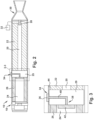
Fig. 2 is an enlarged view of the multi-pulse propulsion system shown inFig. 1 . -
Fig. 3 is an enlarged view of an exemplary passive fuzing system of the multi-pulse propulsion system that is taken from section 3-3 inFig. 2 . -
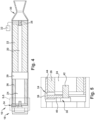
Fig. 4 is an enlarged view of another exemplary embodiment of the multi-pulse propulsion shown inFig. 1 . -
Fig. 5 is an enlarged view of another exemplary embodiment of a passive fuzing system that is taken from section 5-5 inFig. 4 . -
Fig. 6 is a flow chart for using the multi-pulse propulsion system ofFigs. 1-5 . -
Fig. 7 is a schematic of an exemplary long-range trajectory of the flight vehicle inFig. 1 -
Fig. 8 is a schematic of an exemplary short-range trajectory of the flight vehicle inFig. 1 - The principles and aspects described herein have application in defense applications, such as in a hypersonic vehicle or any flight vehicle where space may be constrained. The multi-pulse propulsion system described herein may be implemented in a rocket that includes a multi-pulse rocket motor and carries a warhead. Other suitable applications may include different launching platforms or vehicles that include multi-pulse propulsion systems for launching a payload.
- Referring initially to
Fig. 1 , apropulsion system 10 is shown arranged in aflight vehicle 12, such as a hypersonic vehicle or a rocket. Theflight vehicle 12 includes apayload module 14 having at least one launchable payload. Any suitable payload may be arranged in thepayload module 14 and thepayload module 14 may include a plurality of payloads. Exemplary payloads include satellites, space probes, cargo, or warheads. - The
propulsion system 10 may be arranged in a separable stage of theflight vehicle 12. Theflight vehicle 12 may have any suitable number of separable stages. For example, theflight vehicle 12 may include between two and five separable stages that are separable from theflight vehicle 12 at pre-determined times during travel of theflight vehicle 12. In an exemplary application, theflight vehicle 12 may include at least a first stage and a second stage. The first stage may include a first-stage propulsion device 16 that is arranged opposite thepayload module 14. The first-stage propulsion device 24 may include engines, boosters, tail fins, other thrusters, or any other suitable propulsion devices. - Referring now particularly to
Figs. 2-5 , embodiments of theexemplary propulsion system 10 are shown in further detail. As shown, thepropulsion system 10 includes amulti-pulse rocket motor 18 for providing at least two distinct propulsive pulses. In exemplary embodiments, themulti-pulse rocket motor 18 may be a dual-pulse rocket motor that burns in two segments such that the rocket motor has a first pulse state and an additional pulse state that is initiated after the first pulse state. It is understood that themulti-pulse rocket motor 18 may include any number of pulse states as may be desired for a particular application. - As shown in the illustrated embodiment, the rocket motor includes at least a
first pulse chamber 20 containing a firstburnable propellant 22 for burning during the first pulse state, and asecond pulse chamber 24 containing a secondburnable propellant 26 for burning during a second pulse state. Afirst igniter 28 is located in thefirst pulse chamber 20 and is configured to initiate the first pulse state by igniting the first burnable propellant, which causes pressurization in thefirst pulse chamber 20. Thefirst pulse chamber 20 is configured for pressurization prior to pressurization of thesecond pulse chamber 24, such as by separating thepulse chambers barrier 29. The pressurized gas in thefirst pulse chamber 20 is exhausted throughnozzle assembly 30, thereby generating thrust. As is well-known in the art, thefirst igniter 28 is controlled by anelectronic controller 32, such as the main vehicle computer 32 (e.g., guidance system) to actively initiate the first pulse ignition. - The
first burn propellant 22 contained in thefirst pulse chamber 20 may have different characteristics as compared with the secondburnable propellant 26 contained in thesecond pulse chamber 24. For example, thepropellants pulse chambers propellants propellants pulse chambers flight vehicle 12. - In exemplary embodiments, the
propellants corresponding pulse chambers nozzle assembly 30 to produce thrust for theflight vehicle 12. The shape and size of the propellant grains is predetermined to achieve a specific burn time, amount of exhaust gas, and a thrust level. As shown, thepulse chambers propellants barrier 29, which may be any suitable separation device configured such that during the first pulse state of theflight vehicle 12, thefirst propellant 22 burns separately relative to thesecond propellant 26 which burns during the second pulse state of theflight vehicle 12. Thebarrier 29 may include a bulkhead of theflight vehicle 12 and/or thebarrier 29 may include a suitable thermal barrier, for example. - Referring particularly to
Figs. 3 and5 , exemplary embodiments of apassive fuzing system 34 of themulti-pulse rocket motor 18 are shown in further detail. Thepassive fuzing system 34 is configured to initiate the second pulse state of the motor via ignition of thesecond propellant 26. Any number ofpassive fuzing systems 34 may be provided for initiating the second pulse state, or any subsequent pulse state via ignition of additional propellant in subsequent pulse chambers. As discussed in further detail below, thepassive fuzing system 34 may include one or more passive components or parts that are operable without external triggering logic. In this manner, initiation of the second pulse state and/or subsequent pulse states of therocket motor 18 may be accomplished through activation of thepassive fuzing system 34 independently of initiation by an electronic controller, and more particularly independent of the main vehicle electronics (e.g., main controller 32) that initiates the first pulse state of therocket motor 18. This eliminates or reduces the complexity and volume constraints associated with conventional multi-pulse propulsion systems. Such apassive fuzing system 34, therefore, may be incorporated into smaller vehicle platforms than is currently practical with conventional multi-pulse systems. - As shown in the illustrated embodiments, the
passive fuzing system 34 generally includes at least onesensor 36 and at least oneigniter assembly 38. The sensor(s) (or sensing part(s)) 36 is/are configured to sense an environmental condition and/or ballistic condition of theflight vehicle 12 during flight. As shown, theigniter assembly 38 may include an energetic transfer device 40 (or part) and an igniter 42 (or initiator part). As described in further detail below, theigniter assembly 38, and more particularly theigniter 42, is configured to provide a stimulus that causes ignition of the secondburnable propellant 26 in response to thesensor 36 sensing that the environmental condition and/or ballistic condition has reached or exceeded one or more threshold values. - The
sensor 36, or sensing part, of thepassive fuzing system 34 may be any suitable sensor or sensing part that is capable of sensing or detecting an environmental condition and/or ballistic condition of theflight vehicle 12. Multiple sensors or sensing parts may be utilized for achieving such functionality, which may be singly or collectively referred to hereinafter assensor 36 for simplicity. Thesensor 36 may have any suitable construction for sensing the desired condition. In exemplary embodiments, one or more of the sensor(s) 36 is/are passive devices, such as passive electronic devices, that are operable to sense the desired condition without an external logic controlling the firing current by way of an external electrical signal. Examples of such passive electronic devices include, but are not limited to, one or more of a piezoelectric device, a micro-electro-mechanical system (MEMS) device, a semiconductor device, a shape memory material device, a Peltier device, or the like. - The environmental and/or ballistic condition sensed by the
sensor 36 may be any desired environmental and/or ballistic condition. In exemplary embodiments, the environmental condition sensed by thesensor 36 is temperature and/or pressure. By way of example, and not limitation, a suitable passive temperature sensor may include a thermistor, a thermocouple, a resistance temperature detector, a piezoelectric temperature sensor, or any other suitable passive temperature sensing device or part. By way of example, and not limitation, a suitable passive pressure sensor may include a piezoelectric pressure sensor, a MEMS device, pitot tube, pressure transducer, or any other suitable passive pressure sensing device or part. In exemplary embodiments, the ballistic condition sensed by thesensor 36 is velocity (e.g., linear or angular velocity) and/or acceleration/deceleration. By way of example, and not limitation, a suitable passive ballistic condition sensor may include a MEMS device, such as an accelerometer, or any other suitable passive velocity/acceleration sensing device or part, such as a gyroscope (e.g., a passive resonator gyroscope). - The sensor(s) 36 of the
passive fuzing system 34 may be located at any suitable part of theflight vehicle 12 for sensing the desired condition. For example, the sensor(s) 36 may have an external face that is exposed to the external environment of theflight vehicle 12, which may be atmospheric (e.g., troposphere, stratosphere, mesosphere, thermosphere, exosphere) or outer space. As shown in the illustrated embodiments, for example, the sensor(s) 36 may be located on askin 44 of theflight vehicle 12. Alternatively or additionally, the sensor(s) 36 may be located in a nose cone 15 (seeFig. 1 ) of theflight vehicle 12, for example. - The energetic transfer device 40 (or energetic transfer part) of the
passive fuzing system 34 is configured to transmit energy from thesensor 36 to theigniter 42. As such, theenergetic transfer device 40 is operably coupled to both thesensor 36 and theigniter 42, which may include other components or parts interposed there between for facilitating operation of thepassive fuzing system 34. Theenergetic transfer device 40 may be located at any suitable part of theflight vehicle 12 for providing such operable connection between thesensor 36 andigniter 42, which such placement may be dependent on the type ofenergetic transfer device 40. One or moreenergetic transfer devices 40 may be provided. The energy transferred by theenergetic transfer device 40 may be any form of energy dependent on the particular type ofsensor 36, and the energy from thesensor 36 may be transformed to another type of energy by the energetic transfer device, or other connected component, for transferring to theigniter 42. - By way of example, and not limitation, the
energetic transfer device 40 may transmit electrical energy in the form of current provided by thesensor 36 to theigniter 42, which may activate theigniter 42 to cause ignition of the secondburnable propellant 26. In such a scenario, theenergetic transfer device 40 may include an electrical wire, such as a copper wire, for transmitting the current from thesensor 36 to theigniter 42. - Alternatively or additionally, the
energetic transfer device 40 may include a pyrotechnic device or material that transmits thermal energy to theigniter 42. By way of example, and not limitation, the pyrotechnic device may include a detonation cord, such as a mild detonation cord, for example shielded mild detonation cord, flexible detonation cord, or the like. The pyrotechnic device may include a detonation cord assembly, for example, an RDX filled transfer line with insulative and structural overwraps. The pyrotechnic device may include a suitable blasting cap. The pyrotechnic device may be any other suitable type of fuse. - Alternatively or additionally, the
energetic transfer device 40 may provide a combination of electrical and thermal impulses for causing theigniter 42 to ignite thepropellant 26. For example, an electrical wire may be provided for transmitting an electrical stimulus from thesensor 36 to a blasting cap, which in response to a threshold electrical stimulus by thesensor 36, may detonate the blasting cap to thereby transmit thermal energy that ignites a detonation cord, which thereby transmits thermal energy to activate theigniter 42. Alternatively, for example, a bridgewire may be provided with a pyrotechnic material that is activated when the bridgewire is heated by resistance beyond a threshold level in response to an electrical current from thesensor 36. - The
igniter 42 may be any suitable device or part that provides a sufficient stimulus to cause ignition of thepropellant 26 when theigniter 42 has been activated or triggered. For example, theigniter 42 may include an explosive material, such as a shape charge, which is triggered to explode by energy transferred by the energetic transfer device 40 (e.g., wire or detonation cord). The heat from the explosion of the shape charge will initiate the second pulse via burning ofpropellant 26. - Alternatively or additionally, the
igniter 42 may include a pyrotechnic initiator, which may have a pyrotechnic material composition that causes a self-sustained exothermic chemical reaction when activated to make heat sufficient to burn thepropellant 26. The composition of the pyrotechnic initiator may be adjusted to tune the activation temperature of theigniter 42. Examples of such pyrotechnic initiators include, but are not limited to: metal-oxidizers (e.g., zirconium - potassium perchlorate, boron - potassium nitrate, aluminum-potassium perchlorate, or titanium-aluminum-potassium perchlorate); metal hydride-oxidizer (e.g., zirconium hydride - potassium perchlorate, titanium hydride potassium perchlorate); intermetallics (e.g., titanium-boron, nickel-aluminum, palladium-aluminum); or the like. - The
igniter 42 may be located at any suitable part of theflight vehicle 12 for providing the stimulus that ignites thesecond propellant 26. In exemplary embodiments, theigniter 42 is located in thesecond pulse chamber 24 with sufficient proximity to thepropellant 26 to cause the propellant to burn when theigniter 42 is activated or triggered. - Referring briefly to
Fig. 3 , for example, theigniter 42 may be located proximally to, or coupled to, a surface of thebarrier 29. When activated, theigniter 42 will break down thebarrier 29 to open thepulse chamber 24 to thenozzle assembly 30. Theigniter 42 may break down thebarrier 29 via explosive force (e.g., when theigniter 42 includes a shape charge) and/or theigniter 42 may break down thebarrier 29 via thermal energy (e.g., when theigniter 42 includes a pyrotechnic material). Also when theigniter 42 is activated, theigniter 42 will provide sufficient energetic stimulus to ignite thepropellant 26, thereby causing thepropellant 26 to burn and produce exhaust gas in thechamber 24. With thebarrier 29 destroyed, the exhaust gas is directed through thenozzle assembly 30 to produce thrust for theflight vehicle 12. - Referring briefly to
Fig. 5 , for example, thepassive fuzing system 34 is shown at a different location of theflight vehicle 12 as compared toFig. 3 . As shown, theigniter 42 is located at an opposite (e.g., forward) end of thechamber 24 away from thebarrier 29. Theigniter 42 may be the same as that described above in connection withFig. 3 . In the embodiment illustrated inFig. 5 , when theigniter 42 is activated, theigniter 42 will provide sufficient energetic stimulus to ignite thepropellant 26, thereby causing thepropellant 26 to burn and produce exhaust gas in thechamber 24. The pressure and/or temperature generated by burning thepropellant 26 will break downbarrier 29 to open thechamber 24 to thenozzle assembly 30. With thebarrier 29 destroyed, the exhaust gas is directed through thenozzle assembly 30 to produce thrust for theflight vehicle 12. - Turning now to
Fig. 6 , anexemplary method 100 of operating themulti-pulse rocket motor 18 is shown. As shown, themethod 100 starts atstep 102 with initiating the first pulse state of therocket motor 18, which may be accomplished in a conventional manner as described above. - At
step 104, the sensor(s) 36 of thepassive fuzing system 34 sense the environmental and/or ballistic condition of theflight vehicle 12. This is accomplished as described above, in which the sensor(s) 36 may be configured to sense temperature, pressure, acceleration, velocity, or any other suitable environmental and/or ballistic condition. - At
step 106, thepassive fuzing system 34 is configured to determine whether the environmental and/or ballistic condition sensed by the sensor(s) 36 has reached or exceeded a threshold value. As shown atstep 108, when the sensed condition has reached or exceeded the threshold value, the second pulse state is initiated. The threshold value may be any suitable value which may be adjusted depending on the configuration of thepassive fuzing system 34. By way of example, and not limitation, a threshold temperature value that causes initiation of the second pulse state may be in a range from 700 - 725 °F (644 - 658 K). By way of example, and not limitation, a threshold pressure value that causes initiation of the second pulse state may be in a range from 4 - 5 psi (27579 - 34474 Pa). By way of example, and not limitation, a threshold acceleration value that causes initiation of the second pulse state may be in a range from 80 - 100 ft/sec2 (24.38 -30.48 m/s2). - The determination at
step 106 may be made in any suitable manner dependent on the particular configuration of thepassive fuzing system 34. For example, the energy output from thesensor 36 may vary proportionally to the input condition sensed by thesensor 36. Atstep 108, when the input condition reaches the threshold value, the energy output from thesensor 36 may reach a threshold value that causes, directly or indirectly, activation or triggering of theigniter 42 which initiates the second pulse state of themotor 18, as described above. On the other hand, if the input condition sensed by thesensor 36 does not reach or exceed the threshold value, then the proportional output from thesensor 36 may be insufficient to activate, directly or indirectly, theigniter 42. In this scenario, the sensor(s) 36 will continue to sense the environmental and/or ballistic conditions, as shown in themethod 100 by looping back to step 104. - As discussed above,
multiple sensors 36 may be used to sense the same or different environmental and/or ballistic conditions, and the respective outputs of thesesensors 36 may be combined to reach the activation threshold that causes, directly or indirectly, activation of theigniter 42. Such combination of sensor outputs may enable thepassive fuzing system 34 to require multiple threshold values to be met prior to initiating the second pulse state. As noted above, such energy output from the sensor(s) 36 may be transferred directly to theigniter 42 in the same form, such as via the energetic transfer device 40 (e.g., electrical wire); or the energy output from the sensor(s) 36 may be transferred indirectly by theenergetic transfer device 40 transforming the energy to another form (e.g., blasting cap and/or detonation cord, for example). - A non-limiting example of a
passive fuzing system 34 according to the foregoing will now be described in further detail. In an exemplary system, thesensor 36 is a passive piezoelectric pressure sensor that generates an electrical output signal in response to strain applied to the sensor. The output from the piezoelectric sensor is a charge proportional to the sensed pressure. A small battery may be connected to amplify this charge and/or provide sufficient impetus to ignite a propellant grain. Theenergetic transfer device 40 is an electric wire that transmits this electrical charge to theigniter 42. Theigniter 42 is a shape charge explosive that is configured to detonate when the charge transmitted from the pressure sensor reaches a threshold activation value. This threshold activation value may be achieved when the strain applied to the sensor exceeds a threshold value in response to the environmental pressure sensed reaching a threshold value. - Another non-limiting example of a
passive fuzing system 34 may include asensor 36 in the form of a passive piezoelectric pressure sensor, anenergetic transfer device 40 in the form of a blasting cap and detonation cord operably coupled to the piezoelectric sensor, and anigniter 42 in the form of an intermetallic pyrotechnic material (e.g., Pd/Al) that is operably coupled to the detonation cord. In an exemplary system, thesensor 36 is a passive piezoelectric pressure sensor that generates an electrical output signal in response to strain applied to the sensor. The output from the piezoelectric sensor is a command charge triggered by the sensed pressure. A battery may be connected to amplify this charge. Theenergetic transfer device 40 is blasting cap, the output of which triggers a detonation cord that transmits a combination of heat and/or shock to an igniter. Theigniter 42 contains intermetallic pyrotechnic material that is initiated when the charge output is transmitted from the detonation cord. - Turning to
Figs. 7 and 8 , trajectory shaping of theflight vehicle 12 may be utilized for optimally activating thepassive fuzing system 34 and thereby initiating the second pulse state of therocket motor 18. InFig. 7 , a long range trajectory of theflight vehicle 12 is shown, in which theflight vehicle 12 rockets to a high elevation (such as via the first pulse), and when the threshold condition is met, the second pulse is initiated. In such a scenario, the threshold condition for initiating the second pulse may be a reduction in atmospheric pressure as thevehicle 12 increases in altitude, an increase in temperature as thevehicle 12 re-enters denser atmosphere, or reduction in acceleration as thevehicle 12 loses velocity, for example. InFig. 8 , a short range trajectory of theflight vehicle 12 is shown, in which higher density air may be utilized for reaching the threshold condition (e.g., via heating as thevehicle 12 rockets through the atmosphere). - As discussed above, the exemplary
passive fuzing system 34 may help to eliminate or reduce the complexity and volume constraints associated with conventional multi-pulse propulsion systems. Such a passive system, therefore, may be incorporated into smaller vehicle platforms than is currently practical with conventional multi-pulse systems. For example, theflight vehicle 12 having the exemplarymulti-pulse motor 18 withpassive fuzing system 34 may be used with missiles having diameters of about 125mm or less (e.g., about 5-inches or less), such as missiles having a diameter in the range of about 40mm (e.g., about 1.5-inches) to about 125mm (e.g., about 5-inches). It is of course understood that themulti-pulse rocket motor 18 withpassive fuzing system 34 also may be used with larger diameter missiles or other flight vehicles as well.
Claims (15)
- A multi-pulse propulsion system (10) comprising:at least one pulse chamber (20) containing at least one propellant (22) for igniting during at least one pulse of the multi-pulse propulsion system;a first igniter (28) configured to initiate the at least one pulse by igniting the at least one propellant contained in the at least one pulse chamber, the first igniter being controlled by a main system controller (32);at least one additional pulse chamber (24) containing at least one additional propellant (26) for igniting during at least one additional pulse of the multi-pulse propulsion system, wherein the at least one additional pulse is subsequent to and separate from the at least one pulse, wherein the at least one additional propellant is not ignited until the at least one additional pulse; andat least one passive fuzing system (34) configured to initiate the at least one additional pulse, the at least one passive fuzing system comprising a sensor (36) and a second igniter (42), the sensor being configured to sense an environmental condition and/or a ballistic condition, and the second igniter being configured to provide a stimulus that causes ignition of the at least one additional propellant in response to the sensor sensing that the environmental condition and/or the ballistic condition has reached or exceeded one or more threshold values, wherein the passive fuzing system is operable independent of a connection to the main system controller.
- The multi-pulse propulsion system according to claim 1, or any other preceding claim, wherein the sensor is a passive electronic device.
- The multi-pulse propulsion system according to claim 1, or any other preceding claim, wherein the sensor is a piezoelectric device.
- The multi-pulse propulsion system according to claim 1, or any other preceding claim, wherein the sensor is a micro-electro-mechanical system device, a semiconductor device, a shape memory material device, or a Peltier device.
- The multi-pulse propulsion system according to claim 1, or any other preceding claim, wherein:the environmental condition sensed by the sensor includes temperature or pressure, andwhen a threshold temperature or pressure value is sensed by the sensor, the igniter is activated to ignite the at least one additional propellant, thereby initiating the at least one additional pulse.
- The multi-pulse propulsion system according to claim 1, or any other preceding claim, wherein the sensor is a temperature sensor selected from: a thermistor, a thermocouple, a resistance temperature detector, or a piezoelectric temperature sensor; or
wherein the sensor is a piezoelectric pressure sensor or a micro-electro-mechanical pressure sensor. - The multi-pulse propulsion system according to claim 1, or any other preceding claim, wherein:the ballistic condition sensed by the sensor includes velocity and/or acceleration, andwhen a threshold velocity and/or acceleration value is sensed by the sensor, the igniter is activated to ignite the at least one additional propellant, thereby initiating the at least one additional pulse.
- The multi-pulse propulsion system according to claim 1, or any other preceding claim, wherein the sensor is located in a skin (44) of a flight vehicle (12) that contains the multi-pulse propulsion system; or the sensor is located in a nose cone (15) of the flight vehicle containing the multi-pulse propulsion system.
- The multi-pulse propulsion system according to claim 1, or any other preceding claim, wherein the passive fuzing system further includes an energetic transfer part (40) that is configured to transmit and/or transform energy from the sensor and transfer the energy to the igniter.
- The multi-pulse propulsion system according to claim 9, or any other preceding claim, wherein the energetic transfer part transmits electrical energy from the sensor to the igniter; or
wherein the energetic transfer part is a pyrotechnic device or pyrotechnic material that transmits thermal energy to the igniter. - The multi-pulse propulsion system according to claim 1, or any other preceding claim, wherein the igniter includes an explosive material; or
wherein the igniter includes a pyrotechnic initiator having a pyrotechnic material composition. - The multi-pulse propulsion system according to claim 1, or any other preceding claim, wherein:the at least one pulse chamber is separated from the at least one additional pulse chamber by a barrier (29), andthe igniter is disposed in the at least one additional pulse chamber and coupled to a surface of the barrier ; or.the igniter is located in the at least one additional pulse chamber at an opposite end from the barrier.
- A flight vehicle (12) comprising:a payload (14); anda multi-pulse propulsion system (10) according to claim 1.
- The flight vehicle according to claim 13, wherein the flight vehicle has a diameter in the range from 40mm to 130mm.
- A method (100) of operating a multi-pulse propulsion system (10) of a flight vehicle (12), comprising:sensing (104) an environmental condition and/or a ballistic condition of the flight vehicle with a sensor (36) of a passive fuzing system (34) of the multi-pulse propulsion system;determining (106) with the passive fuzing system when the environmental condition and/or the ballistic condition has reached or exceed a threshold environmental condition value and/or a threshold ballistic condition value; andwhen the environmental condition and/or the ballistic condition has reached or exceed the threshold environmental condition value, initiating (108) a second pulse of the multi-pulse propulsion system by igniting a second propellant (26) contained in a second pulse chamber (24) of the multi-pulse propulsion system, wherein the multi-pulse propulsion further includes;a first pulse chamber (20) containing at least one first propellant (22) for igniting during a first pulse of the multi-pulse propulsion system; anda first igniter (28) configured to initiate (102) the first pulse by igniting the first propellant (22) contained in the first pulse chamber, wherein the first igniter being controlled by a main system controller (34);wherein the passive fuzing system is operable independent of a correction to the main system controller, wherein the first pulse is prior to and separate from the second pulse, wherein the second propellant in the second pulse chamber is not ignited until the second pulse.
Applications Claiming Priority (2)
| Application Number | Priority Date | Filing Date | Title |
|---|---|---|---|
| US17/075,987 US11988173B2 (en) | 2020-10-21 | 2020-10-21 | Multi-pulse propulsion system with passive initiation |
| PCT/US2021/017415 WO2022086587A1 (en) | 2020-10-21 | 2021-02-10 | Multi-pulse propulsion system with passive initiation |
Publications (2)
| Publication Number | Publication Date |
|---|---|
| EP4232701A1 EP4232701A1 (en) | 2023-08-30 |
| EP4232701B1 true EP4232701B1 (en) | 2025-06-11 |
Family
ID=77595609
Family Applications (1)
| Application Number | Title | Priority Date | Filing Date |
|---|---|---|---|
| EP21763426.0A Active EP4232701B1 (en) | 2020-10-21 | 2021-02-10 | Multi-pulse propulsion system with passive initiation |
Country Status (3)
| Country | Link |
|---|---|
| US (1) | US11988173B2 (en) |
| EP (1) | EP4232701B1 (en) |
| WO (1) | WO2022086587A1 (en) |
Families Citing this family (1)
| Publication number | Priority date | Publication date | Assignee | Title |
|---|---|---|---|---|
| CN115839290B (en) * | 2022-12-16 | 2025-02-14 | 西安长峰机电研究所 | A dynamic closed-loop ignition control method and device for a dual-pulse solid rocket engine |
Family Cites Families (81)
| Publication number | Priority date | Publication date | Assignee | Title |
|---|---|---|---|---|
| NL294375A (en) * | 1962-06-30 | |||
| US3420176A (en) | 1967-04-10 | 1969-01-07 | Umc Ind | Electrical pyrotechnic programming system |
| FR2545599B1 (en) | 1974-08-29 | 1986-10-24 | France Etat Armement | PROXIMITY ROCKET |
| FR2674621B1 (en) | 1977-07-29 | 1994-08-26 | Thomson Brandt | PROJECTILE GUIDE. |
| DE2819863A1 (en) | 1978-03-14 | 1986-07-24 | Buck Chemisch-Technische Werke Gmbh & Co, 8230 Bad Reichenhall | THROWING BODY |
| DE2831420A1 (en) | 1978-07-18 | 1980-01-31 | Licentia Gmbh | Proximity fuse for projectiles directed against landing boats - detonates above boat or converts into naval mine upon submergence |
| US4372239A (en) | 1980-03-03 | 1983-02-08 | General Dynamics, Pomona Division | Undersea weapon with hydropulse system and periodical seawater admission |
| FR2728676B1 (en) | 1982-05-11 | 1997-03-21 | France Etat | HORIZONTAL-ACTION PYROTECHNIC CHARGE FIRE CONTROL SYSTEM |
| FR2543288B1 (en) | 1983-03-23 | 1987-07-17 | Luchaire Sa | ROCKET BUMPER |
| DE3603497C1 (en) | 1986-02-05 | 1993-01-07 | Rheinmetall Gmbh | Bullet for an anti-tank weapon to fight a tank from above |
| US4798142A (en) | 1986-08-18 | 1989-01-17 | Morton Thiokol, Inc. | Rapid buring propellant charge for automobile air bag inflators, rocket motors, and igniters therefor |
| US5024160A (en) | 1986-08-18 | 1991-06-18 | Thiokol Corporation | Rapid burning propellant charge for automobile air bag inflators, rocket motors, and igniters therefor |
| US5062365A (en) | 1986-08-18 | 1991-11-05 | Thiokol Corporation | Rapid burning propellent charge for automobile air bag inflators, rocket motors, and igniters therefor |
| US5127223A (en) | 1986-09-18 | 1992-07-07 | Thiokol Corporation | Solid rocket motor propellants with reticulated structures embedded therein and method of manufacture thereof |
| FR2726360B1 (en) | 1986-12-23 | 1997-04-11 | Thomson Trt Defense | PROCESS FOR THE PREPARATION OF AN AUTOMATIC IGNITION ORDER FOR A TRUCK AND IGNITOR TRAP FOR IMPLEMENTING THE PROCESS |
| US5206989A (en) * | 1988-08-03 | 1993-05-04 | Thiokol Corporation | Method of making solid propellant canister loaded rocket motor |
| US5109669A (en) | 1989-09-28 | 1992-05-05 | Rockwell International Corporation | Passive self-contained auto ignition system |
| US5166468A (en) * | 1991-04-05 | 1992-11-24 | Thiokol Corporation | Thermocouple-triggered igniter |
| AP790A (en) | 1994-03-02 | 1999-12-16 | William C Orr | Fuel for advance vapour phase combustion. |
| DE4435319A1 (en) | 1994-10-01 | 1996-04-04 | Temic Bayern Chem Airbag Gmbh | Ignition unit for a gas generator of a passive restraint system |
| US7578122B1 (en) | 1995-02-24 | 2009-08-25 | Aerojet General Corporation | Rocket motor case using plank sections and method of manufacture |
| RU2133864C1 (en) | 1997-09-10 | 1999-07-27 | Государственное научно-производственное предприятие "Сплав" | Solid-propellant rocket engine |
| JP2003516197A (en) | 1999-12-11 | 2003-05-13 | グラクソ グループ リミテッド | Drug dispenser |
| US7047885B1 (en) * | 2000-02-14 | 2006-05-23 | Alliant Techsystems Inc. | Multiple pulse cartridge ignition system |
| US6584907B2 (en) * | 2000-03-17 | 2003-07-01 | Ensign-Bickford Aerospace & Defense Company | Ordnance firing system |
| US6958813B1 (en) | 2000-05-22 | 2005-10-25 | The United States Of America As Represented By The Secretary Of The Air Force | Plume detector |
| US6523475B2 (en) | 2000-09-28 | 2003-02-25 | Superior Ballistics, Inc. | Firearm cartridge and case-less chamber |
| US7931614B2 (en) | 2000-11-30 | 2011-04-26 | Valeritas, Inc. | Injection systems |
| CN1514871A (en) | 2001-03-22 | 2004-07-21 | 奥瑞克斯能源国际公司 | Use of materials of plant origin in petroleum to reduce emissions |
| US20020196152A1 (en) * | 2001-06-20 | 2002-12-26 | Eric Wilson | Automated fire protection system |
| US6769241B2 (en) | 2001-07-09 | 2004-08-03 | W. E. Research Llc | Description of methods to increase propellant throughput in a micro pulsed plasma thruster |
| RU2225586C1 (en) | 2002-07-09 | 2004-03-10 | Федеральное Государственное унитарное предприятие "Государственное научно-производственное предприятие "Сплав" | Cassette warhead |
| FR2844557B1 (en) | 2002-09-12 | 2006-03-03 | Snecma Propulsion Solide | SYSTEM AND METHOD FOR CONTROLLING PRESSURE OSCILLATIONS OF HYDRODYNAMIC ORIGIN FOR SOLID PROPERGOL PROPELLER |
| CN1403781A (en) | 2002-10-21 | 2003-03-19 | 张宝林 | Portable dual high-speed air defense missile |
| US7000377B1 (en) | 2004-04-26 | 2006-02-21 | Knight Andrew F | Super-staged and continuously staged rocket |
| US7202809B1 (en) | 2004-05-10 | 2007-04-10 | Bae Systems Land & Armaments L.P. | Fast acting active protection system |
| CN100480488C (en) | 2004-12-28 | 2009-04-22 | 蒋子刚 | Kneading positive-displacement method of fluid machinery and mechanism and purpose thereof |
| CN2799011Y (en) | 2005-03-18 | 2006-07-26 | 张森 | Supersonic-speed dry powder extinguishing apparatus with long-period propulsion function |
| US7565795B1 (en) | 2006-01-17 | 2009-07-28 | Pratt & Whitney Rocketdyne, Inc. | Piezo-resonance igniter and ignition method for propellant liquid rocket engine |
| WO2008082427A1 (en) | 2006-02-13 | 2008-07-10 | Halkey-Roberts Corporation | Apparatus and method for using tetrazine-based energetic material |
| ZA200902205B (en) | 2006-10-10 | 2010-09-29 | Amyris Biotechnologies Inc | Fuel compositions comprising farnesane and farnesane derivatives and method of making and using same |
| CN200970429Y (en) | 2006-11-10 | 2007-11-07 | 成都神剑消防科技有限公司 | Supersonic dry power fire extinguisher with external insertion and built-in startor |
| US10286599B2 (en) | 2007-03-22 | 2019-05-14 | Ronald D Jones | Additive manufactured thermoplastic-nanocomposite aluminum hybrid rocket fuel grain and method of manufacturing same |
| US9822045B2 (en) | 2007-03-22 | 2017-11-21 | Ronald D Jones | Additive manufactured thermoplastic-aluminum nanocomposite hybrid rocket fuel grain and method of manufacturing same |
| FR2914368B1 (en) | 2007-03-30 | 2009-10-16 | Snecma Sa | ELECTROLYTIC IGNITER FOR FLUID ERGOL ENGINE-FUSE |
| US10581347B2 (en) * | 2007-07-10 | 2020-03-03 | Omnitek Partners Llc | Manually operated piezoelectric energy harvesting electronic circuitry |
| EP2173837A2 (en) | 2007-07-20 | 2010-04-14 | Amyris Biotechnologies, Inc. | Fuel compositions comprising tetramethylcyclohexane |
| FR2924410B1 (en) | 2007-11-29 | 2010-06-11 | Astrium Sas | DEVICE FOR REDUCING AERODYNAMIC TRAINING |
| WO2012003706A1 (en) | 2010-07-07 | 2012-01-12 | Jin Beibiao | Supersonic rotor engine |
| US8434411B2 (en) * | 2011-01-19 | 2013-05-07 | Raytheon Company | Cluster explosively-formed penetrator warheads |
| ITMI20111332A1 (en) | 2011-07-18 | 2013-01-19 | Orbit S R L D | DEVICE FOR THE DEORBITATION OF ARTIFICIAL SATELLITES. |
| IL217450A (en) | 2012-01-10 | 2017-02-28 | Israel Aerospace Ind Ltd | Anti-rocket system |
| US9853744B2 (en) | 2012-01-17 | 2017-12-26 | Hadal, Inc. | Systems and methods for transmitting data from an underwater station |
| US8966879B1 (en) | 2012-02-15 | 2015-03-03 | Orbital Technologies Corporation | Acoustic igniter |
| US9062712B1 (en) | 2012-02-27 | 2015-06-23 | The United States Of America As Represented By The Administrator Of The National Aeronautics And Space Administration | Passive thermal management of foil bearings |
| SG10201608883SA (en) | 2012-04-25 | 2016-12-29 | Elta Systems Ltd | Estimating a source location of a projectile |
| US9476399B1 (en) | 2012-05-16 | 2016-10-25 | Orbital Technologies Corporation | Glow plug type acoustic resonance igniter |
| US9227883B2 (en) | 2012-07-31 | 2016-01-05 | Purdue Research Foundation | Mechanically activated metal fuels for energetic material applications |
| CN103194284B (en) | 2013-04-22 | 2015-05-06 | 黑龙江省能源环境研究院 | Composite regulator for vehicle gasoline |
| JP2015006650A (en) | 2013-06-26 | 2015-01-15 | 須知 晃一 | Manufacturing method and constituent materials of cell structure structure cell composite objects |
| RU2561182C2 (en) | 2013-08-08 | 2015-08-27 | Николай Евгеньевич Староверов | Parachute system/versions and its control system/versions |
| US9881706B2 (en) | 2013-08-23 | 2018-01-30 | Global Energy Research Associates, LLC | Nuclear powered rotary internal engine apparatus |
| US9947423B2 (en) | 2013-08-23 | 2018-04-17 | Global Energy Research Associates, LLC | Nanofuel internal engine |
| CN103670797B (en) | 2013-12-06 | 2015-12-09 | 北京动力机械研究所 | A kind of solid-liquid scramjet engine |
| US9518802B2 (en) | 2014-01-06 | 2016-12-13 | Yanwei Wei | Multi-launcher firearm |
| CN104989551A (en) | 2015-07-08 | 2015-10-21 | 杜善骥 | Working method of Laval nozzle effect ram rocket |
| CN105114208A (en) | 2015-07-18 | 2015-12-02 | 杜善骥 | Working method for Laval nozzle effect detonation ram rocket |
| CN105065138A (en) | 2015-07-19 | 2015-11-18 | 杜善骥 | Working method of detonation punching oxygen-generation rocket based on Laval nozzle effect |
| CN105065137A (en) | 2015-07-19 | 2015-11-18 | 杜善骥 | Working method of Laval nozzle effect detonation superposition ram rocket |
| CN105134411A (en) | 2015-09-02 | 2015-12-09 | 杜善骥 | Working method of detonation ram Laval nozzle effect propelled and oxygen-producing rocket |
| US10107601B2 (en) | 2015-10-06 | 2018-10-23 | Raytheon Company | Electrically operated pulse initiators and ignition |
| CN105971767B (en) | 2016-05-19 | 2018-08-24 | 湖北三江航天江河化工科技有限公司 | A kind of solid booster rocket engine |
| CN106988929B (en) | 2017-03-06 | 2018-07-24 | 西安航天动力技术研究所 | A kind of solid propellant rocket gap test method |
| RO133060B1 (en) | 2017-07-28 | 2023-11-29 | Mihail Sima | Equipment and method of launching anti-hail reactive rockets with self-propelled guided platform |
| CN107796270A (en) | 2017-11-29 | 2018-03-13 | 四川蓝狮科技有限公司 | A kind of delay igniter |
| WO2019123801A1 (en) | 2017-12-19 | 2019-06-27 | 明倫 久米 | Lifesaving tool for water accident and tool, device, and method applying same |
| WO2019146595A1 (en) | 2018-01-23 | 2019-08-01 | 久米明倫 | Life-saving implement for accident on water, and tool, device and method employing same |
| RU2678726C1 (en) | 2018-01-29 | 2019-01-31 | Акционерное общество "Корпорация "Московский институт теплотехники" (АО "Корпорация "МИТ") | Powder pressure accumulator for mortar scheme of separation of rocket stages in flight |
| CN108894893B (en) | 2018-06-26 | 2020-02-07 | 西北工业大学 | Liquid film cooling ejection rocket engine thrust chamber for rocket stamping combined engine |
| CN109441664A (en) | 2018-12-29 | 2019-03-08 | 湖北航天技术研究院总体设计所 | A kind of soft interlayer of integration dipulse solid engines |
| CN110237462B (en) | 2019-06-10 | 2022-02-08 | 西北工业大学 | Hard shell type fire extinguishing bomb adopting flexible inner container |
-
2020
- 2020-10-21 US US17/075,987 patent/US11988173B2/en active Active
-
2021
- 2021-02-10 WO PCT/US2021/017415 patent/WO2022086587A1/en not_active Ceased
- 2021-02-10 EP EP21763426.0A patent/EP4232701B1/en active Active
Also Published As
| Publication number | Publication date |
|---|---|
| US20220120241A1 (en) | 2022-04-21 |
| WO2022086587A1 (en) | 2022-04-28 |
| EP4232701A1 (en) | 2023-08-30 |
| US11988173B2 (en) | 2024-05-21 |
Similar Documents
| Publication | Publication Date | Title |
|---|---|---|
| US7947938B2 (en) | Methods and apparatus for projectile guidance | |
| US8931415B2 (en) | Initiation systems for explosive devices, scalable output explosive devices including initiation systems, and related methods | |
| US6105505A (en) | Hard target incendiary projectile | |
| US11499505B2 (en) | Multi-pulse rocket motor with flight termination destruct charge | |
| US8546736B2 (en) | Modular guided projectile | |
| US9605932B2 (en) | Gas generators, launch tubes including gas generators and related systems and methods | |
| EP2203708B1 (en) | Method of varying firing range and effect in target for shell and shell configured for this purpose | |
| US4213393A (en) | Gun projectile arranged with a base drag reducing system | |
| US7762195B2 (en) | Slow cook off rocket igniter | |
| EP2271887A1 (en) | Method and apparatus for fast action impulse thruster | |
| US5440993A (en) | High velocity impulse rocket | |
| AU6149290A (en) | Lateral thrust assembly for missiles | |
| US5353711A (en) | Extended range artillery projectile | |
| EP1851501B1 (en) | Methods and apparatus for selectable velocity projectile system | |
| EP4232701B1 (en) | Multi-pulse propulsion system with passive initiation | |
| US20090212163A1 (en) | Propulsion Enhancement Arrangement for Rocket | |
| US3296967A (en) | Incendiary device | |
| US6000340A (en) | Rocket launching system employing thermal-acoustic detection for rocket ignition | |
| US5153369A (en) | Safe and arm device with expansible element in liquid explosive | |
| EP4251871B1 (en) | Multi-pulse solid propellant rocket motor and ignition method | |
| EP4232700B1 (en) | Integrated propulsion and warhead system for an artillery round | |
| US6796242B2 (en) | Propulsion enhancement arrangement for rocket | |
| US10030951B2 (en) | Drag reduction system | |
| US3273337A (en) | Linear explosive type igniter train for rocket motor | |
| RU2247932C1 (en) | Method for launching of jet projectile and complex of armament for its realization |
Legal Events
| Date | Code | Title | Description |
|---|---|---|---|
| STAA | Information on the status of an ep patent application or granted ep patent |
Free format text: STATUS: UNKNOWN |
|
| STAA | Information on the status of an ep patent application or granted ep patent |
Free format text: STATUS: THE INTERNATIONAL PUBLICATION HAS BEEN MADE |
|
| PUAI | Public reference made under article 153(3) epc to a published international application that has entered the european phase |
Free format text: ORIGINAL CODE: 0009012 |
|
| STAA | Information on the status of an ep patent application or granted ep patent |
Free format text: STATUS: REQUEST FOR EXAMINATION WAS MADE |
|
| 17P | Request for examination filed |
Effective date: 20230420 |
|
| AK | Designated contracting states |
Kind code of ref document: A1 Designated state(s): AL AT BE BG CH CY CZ DE DK EE ES FI FR GB GR HR HU IE IS IT LI LT LU LV MC MK MT NL NO PL PT RO RS SE SI SK SM TR |
|
| DAV | Request for validation of the european patent (deleted) | ||
| DAX | Request for extension of the european patent (deleted) | ||
| GRAP | Despatch of communication of intention to grant a patent |
Free format text: ORIGINAL CODE: EPIDOSNIGR1 |
|
| STAA | Information on the status of an ep patent application or granted ep patent |
Free format text: STATUS: GRANT OF PATENT IS INTENDED |
|
| INTG | Intention to grant announced |
Effective date: 20250225 |
|
| GRAS | Grant fee paid |
Free format text: ORIGINAL CODE: EPIDOSNIGR3 |
|
| GRAA | (expected) grant |
Free format text: ORIGINAL CODE: 0009210 |
|
| STAA | Information on the status of an ep patent application or granted ep patent |
Free format text: STATUS: THE PATENT HAS BEEN GRANTED |
|
| AK | Designated contracting states |
Kind code of ref document: B1 Designated state(s): AL AT BE BG CH CY CZ DE DK EE ES FI FR GB GR HR HU IE IS IT LI LT LU LV MC MK MT NL NO PL PT RO RS SE SI SK SM TR |
|
| REG | Reference to a national code |
Ref country code: GB Ref legal event code: FG4D |
|
| REG | Reference to a national code |
Ref country code: CH Ref legal event code: EP |
|
| REG | Reference to a national code |
Ref country code: DE Ref legal event code: R096 Ref document number: 602021032169 Country of ref document: DE |
|
| REG | Reference to a national code |
Ref country code: IE Ref legal event code: FG4D |
|
| PG25 | Lapsed in a contracting state [announced via postgrant information from national office to epo] |
Ref country code: FI Free format text: LAPSE BECAUSE OF FAILURE TO SUBMIT A TRANSLATION OF THE DESCRIPTION OR TO PAY THE FEE WITHIN THE PRESCRIBED TIME-LIMIT Effective date: 20250611 Ref country code: ES Free format text: LAPSE BECAUSE OF FAILURE TO SUBMIT A TRANSLATION OF THE DESCRIPTION OR TO PAY THE FEE WITHIN THE PRESCRIBED TIME-LIMIT Effective date: 20250611 |
|
| REG | Reference to a national code |
Ref country code: LT Ref legal event code: MG9D |
|
| PG25 | Lapsed in a contracting state [announced via postgrant information from national office to epo] |
Ref country code: GR Free format text: LAPSE BECAUSE OF FAILURE TO SUBMIT A TRANSLATION OF THE DESCRIPTION OR TO PAY THE FEE WITHIN THE PRESCRIBED TIME-LIMIT Effective date: 20250912 |
|
| REG | Reference to a national code |
Ref country code: NL Ref legal event code: MP Effective date: 20250611 |
|
| PG25 | Lapsed in a contracting state [announced via postgrant information from national office to epo] |
Ref country code: BG Free format text: LAPSE BECAUSE OF FAILURE TO SUBMIT A TRANSLATION OF THE DESCRIPTION OR TO PAY THE FEE WITHIN THE PRESCRIBED TIME-LIMIT Effective date: 20250611 |
|
| PG25 | Lapsed in a contracting state [announced via postgrant information from national office to epo] |
Ref country code: HR Free format text: LAPSE BECAUSE OF FAILURE TO SUBMIT A TRANSLATION OF THE DESCRIPTION OR TO PAY THE FEE WITHIN THE PRESCRIBED TIME-LIMIT Effective date: 20250611 |
|
| PG25 | Lapsed in a contracting state [announced via postgrant information from national office to epo] |
Ref country code: RS Free format text: LAPSE BECAUSE OF FAILURE TO SUBMIT A TRANSLATION OF THE DESCRIPTION OR TO PAY THE FEE WITHIN THE PRESCRIBED TIME-LIMIT Effective date: 20250911 |
|
| PG25 | Lapsed in a contracting state [announced via postgrant information from national office to epo] |
Ref country code: LV Free format text: LAPSE BECAUSE OF FAILURE TO SUBMIT A TRANSLATION OF THE DESCRIPTION OR TO PAY THE FEE WITHIN THE PRESCRIBED TIME-LIMIT Effective date: 20250611 |
|
| PG25 | Lapsed in a contracting state [announced via postgrant information from national office to epo] |
Ref country code: NL Free format text: LAPSE BECAUSE OF FAILURE TO SUBMIT A TRANSLATION OF THE DESCRIPTION OR TO PAY THE FEE WITHIN THE PRESCRIBED TIME-LIMIT Effective date: 20250611 |
|
| PG25 | Lapsed in a contracting state [announced via postgrant information from national office to epo] |
Ref country code: PT Free format text: LAPSE BECAUSE OF FAILURE TO SUBMIT A TRANSLATION OF THE DESCRIPTION OR TO PAY THE FEE WITHIN THE PRESCRIBED TIME-LIMIT Effective date: 20251013 |
|
| REG | Reference to a national code |
Ref country code: AT Ref legal event code: MK05 Ref document number: 1802441 Country of ref document: AT Kind code of ref document: T Effective date: 20250611 |
|
| PG25 | Lapsed in a contracting state [announced via postgrant information from national office to epo] |
Ref country code: IS Free format text: LAPSE BECAUSE OF FAILURE TO SUBMIT A TRANSLATION OF THE DESCRIPTION OR TO PAY THE FEE WITHIN THE PRESCRIBED TIME-LIMIT Effective date: 20251011 |
|
| PG25 | Lapsed in a contracting state [announced via postgrant information from national office to epo] |
Ref country code: AT Free format text: LAPSE BECAUSE OF FAILURE TO SUBMIT A TRANSLATION OF THE DESCRIPTION OR TO PAY THE FEE WITHIN THE PRESCRIBED TIME-LIMIT Effective date: 20250611 Ref country code: SM Free format text: LAPSE BECAUSE OF FAILURE TO SUBMIT A TRANSLATION OF THE DESCRIPTION OR TO PAY THE FEE WITHIN THE PRESCRIBED TIME-LIMIT Effective date: 20250611 |
|
| PG25 | Lapsed in a contracting state [announced via postgrant information from national office to epo] |
Ref country code: CZ Free format text: LAPSE BECAUSE OF FAILURE TO SUBMIT A TRANSLATION OF THE DESCRIPTION OR TO PAY THE FEE WITHIN THE PRESCRIBED TIME-LIMIT Effective date: 20250611 |
|
| PG25 | Lapsed in a contracting state [announced via postgrant information from national office to epo] |
Ref country code: PL Free format text: LAPSE BECAUSE OF FAILURE TO SUBMIT A TRANSLATION OF THE DESCRIPTION OR TO PAY THE FEE WITHIN THE PRESCRIBED TIME-LIMIT Effective date: 20250611 |
|
| PG25 | Lapsed in a contracting state [announced via postgrant information from national office to epo] |
Ref country code: EE Free format text: LAPSE BECAUSE OF FAILURE TO SUBMIT A TRANSLATION OF THE DESCRIPTION OR TO PAY THE FEE WITHIN THE PRESCRIBED TIME-LIMIT Effective date: 20250611 |
|
| PG25 | Lapsed in a contracting state [announced via postgrant information from national office to epo] |
Ref country code: SK Free format text: LAPSE BECAUSE OF FAILURE TO SUBMIT A TRANSLATION OF THE DESCRIPTION OR TO PAY THE FEE WITHIN THE PRESCRIBED TIME-LIMIT Effective date: 20250611 |
|
| REG | Reference to a national code |
Ref country code: DE Ref legal event code: R097 Ref document number: 602021032169 Country of ref document: DE |
|
| PGFP | Annual fee paid to national office [announced via postgrant information from national office to epo] |
Ref country code: GB Payment date: 20260121 Year of fee payment: 6 |
|
| PG25 | Lapsed in a contracting state [announced via postgrant information from national office to epo] |
Ref country code: DK Free format text: LAPSE BECAUSE OF FAILURE TO SUBMIT A TRANSLATION OF THE DESCRIPTION OR TO PAY THE FEE WITHIN THE PRESCRIBED TIME-LIMIT Effective date: 20250611 |
|
| PGFP | Annual fee paid to national office [announced via postgrant information from national office to epo] |
Ref country code: NO Payment date: 20260123 Year of fee payment: 6 Ref country code: DE Payment date: 20260121 Year of fee payment: 6 |
|
| PG25 | Lapsed in a contracting state [announced via postgrant information from national office to epo] |
Ref country code: IT Free format text: LAPSE BECAUSE OF FAILURE TO SUBMIT A TRANSLATION OF THE DESCRIPTION OR TO PAY THE FEE WITHIN THE PRESCRIBED TIME-LIMIT Effective date: 20250611 |
|
| PLBE | No opposition filed within time limit |
Free format text: ORIGINAL CODE: 0009261 |
|
| STAA | Information on the status of an ep patent application or granted ep patent |
Free format text: STATUS: NO OPPOSITION FILED WITHIN TIME LIMIT |
|
| PGFP | Annual fee paid to national office [announced via postgrant information from national office to epo] |
Ref country code: FR Payment date: 20260121 Year of fee payment: 6 |
|
| REG | Reference to a national code |
Ref country code: CH Ref legal event code: L10 Free format text: ST27 STATUS EVENT CODE: U-0-0-L10-L00 (AS PROVIDED BY THE NATIONAL OFFICE) Effective date: 20260423 |