EP4232686B1 - Druckbetätigtes ventil zur verwendung während der installation und inbetriebnahme eines produktionsstranges - Google Patents
Druckbetätigtes ventil zur verwendung während der installation und inbetriebnahme eines produktionsstranges Download PDFInfo
- Publication number
- EP4232686B1 EP4232686B1 EP21801056.9A EP21801056A EP4232686B1 EP 4232686 B1 EP4232686 B1 EP 4232686B1 EP 21801056 A EP21801056 A EP 21801056A EP 4232686 B1 EP4232686 B1 EP 4232686B1
- Authority
- EP
- European Patent Office
- Prior art keywords
- piston
- cylinder
- activated valve
- pressure
- pressure activated
- Prior art date
- Legal status (The legal status is an assumption and is not a legal conclusion. Google has not performed a legal analysis and makes no representation as to the accuracy of the status listed.)
- Active
Links
Images


Classifications
-
- E—FIXED CONSTRUCTIONS
- E21—EARTH OR ROCK DRILLING; MINING
- E21B—EARTH OR ROCK DRILLING; OBTAINING OIL, GAS, WATER, SOLUBLE OR MELTABLE MATERIALS OR A SLURRY OF MINERALS FROM WELLS
- E21B23/00—Apparatus for displacing, setting, locking, releasing or removing tools, packers or the like in boreholes or wells
- E21B23/004—Indexing systems for guiding relative movement between telescoping parts of downhole tools
- E21B23/006—"J-slot" systems, i.e. lug and slot indexing mechanisms
-
- E—FIXED CONSTRUCTIONS
- E21—EARTH OR ROCK DRILLING; MINING
- E21B—EARTH OR ROCK DRILLING; OBTAINING OIL, GAS, WATER, SOLUBLE OR MELTABLE MATERIALS OR A SLURRY OF MINERALS FROM WELLS
- E21B34/00—Valve arrangements for boreholes or wells
- E21B34/06—Valve arrangements for boreholes or wells in wells
- E21B34/10—Valve arrangements for boreholes or wells in wells operated by control fluid supplied from outside the borehole
- E21B34/102—Valve arrangements for boreholes or wells in wells operated by control fluid supplied from outside the borehole with means for locking the closing element in open or closed position
-
- E—FIXED CONSTRUCTIONS
- E21—EARTH OR ROCK DRILLING; MINING
- E21B—EARTH OR ROCK DRILLING; OBTAINING OIL, GAS, WATER, SOLUBLE OR MELTABLE MATERIALS OR A SLURRY OF MINERALS FROM WELLS
- E21B43/00—Methods or apparatus for obtaining oil, gas, water, soluble or meltable materials or a slurry of minerals from wells
- E21B43/12—Methods or apparatus for controlling the flow of the obtained fluid to or in wells
Definitions
- the invention concerns a pressure activated valve to prevent fluid from flowing through an inflow control device during installation and commissioning of a production string of a wellbore.
- some autonomous ICDs allow at least a small amount of fluid to pass through the autonomous ICD even when in choking/closed position. This can be due to a pilot/secondary flow path of the autonomous ICDs which regulates the valve element(s) as this path is always open. Hence, the fluid and pressure within the production string is not fully controlled. Hence, a closed system is desirable.
- the purpose of the present invention is to overcome the shortcomings of the prior art and to obtain further advantages.
- the PAV of the present invention is hence configured to prevent fluid from running through an ICD or an autonomous ICD at least during installation and commissioning of a production pipe of a well bore.
- either the cylinder comprises a slot for receiving and guiding a stopper which is fixed to the piston or the piston comprises a slot for receiving and guiding a stopper which is fixed to the cylinder.
- the slot is configured to guide the stopper such that the piston is guided from
- the piston may have at least three radially arranged openings arranged next to each other in the circumferential direction of the piston.
- the openings are preferably equally spaced apart from each other.
- the slot is configured to guide the stopper therein when moving the piston within the cylinder.
- the slot may be in the form of a slit opening or a groove when arranged on the cylinder and may be in the form of a groove when arranged on the piston.
- the stopper may comprise several components and the portion interacting with the slot may be free to rotate.
- the cylinder may comprise the slot while the stopper is fixed to an outer surface of the piston.
- the piston of the PAV comprises the slot while the stopper is fixed to the cylinder.
- the slot may be in the form of a groove arranged on the outer surface of the piston of the PAV.
- the outer surface of the piston is considered to be the surface facing the inner surface of the cylinder.
- the stopper is in this example aspect arranged on the cylinder. By moving the piston, the stopper is guided within a path formed by the groove on the piston.
- the PAV according to the second aspect may in an example embodiment have the same functions as disclosed for the first example aspect above but with inverse stopper and groove positions.
- the working principle/operation of the PAV of the second aspect can hence be very similar to the working principle of the first example aspect.
- the path made by the groove may in another example embodiment allow for the PAV to be reversible on repressurization and may create an alternating fully opened and fully closed position for pressures in both directions i.e. both internal and external pressures.
- the stopper should have a geometry that allows the stopper to interact within the path of the groove by sliding or rolling.
- the groove may have a configuration that only allows the stopper to be guided in one direction, such as for example ramps.
- the present invention also involves a method for preventing fluid flow through an ICD or autonomous ICD arranged within a wall of a production string using a PAV in accordance with the system disclosed above.
- the method comprises the steps of:
- longitudinal direction should be understood as the direction along the longitudinal length of the cylinder of the PAV.
- set value/design pressure is the spring force that the piston is exposed to in its first position before activation of the PAV by the activation pressure.
- design pressure can be understood as the pressure generating a force that is equal to the spring's pretensioned force when the piston is positioned in the pretensioned first position wherein the stopper is preloaded. Hence, pressure lower than the design pressure will not move the piston while pressure above the design pressure will move the piston.
- the piston of the PAV can be moved back towards the second position, P2, after being arranged at the third position, P3, if the PAV is made such that it is biased to close the opening in an intermediate position, e.g. by shortening the stroke of the spring and adding a second opposing spring.
- the PAV will obtain a check-valve function after activation. It will open on flow into the well by the external pressure, but close if pressure is reversed. Increase in internal pressure of the production pipe will first seat the seal in the intermediate position between the second position P2 and the third position P3, then the piston will move inside the cylinder to position P2 where the pressure can further be increased without movement of the piston. When the pressure is again released the piston will go back to the intermediate check valve state i.e. the piston will be moved into the intermediate position.
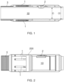
- the AICV 2 is mounted within the wall of the production string 10 to create a flow path there through, while the PAVs 1 and sand screen 3 are mounted on the outside of the production string along the outer surface thereof.
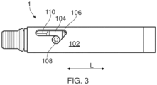
- Fig. 3 is a perspective view of a PAV 1 according to a first example embodiment of the first aspect of the PAV 1 showing the cylinder 102 having two slots 110, even if only one is visible. Further, the shown stopper 108 of the piston 104 is arranged in the first position P1 being pretensioned by the force from the spring 106 into the shown abutting position.
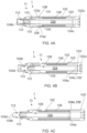
- Figs. 4A to 4C are cross-sectional views of the PAV 1 shown in Fig. 3 and Figs 5A to 5C are open transparent side views of the PAV 1 shown in Figs. 4A to 4C .
- the PAV 1 is shown in the pretensioned closed position P1 in Figs. 4A and 5A , in a closed second position P2 in Figs. 4B and 5B and in an open third position P3 in Figs. 4C and 5C .
- the spring 106 is pretensioned between the first piston rim 105 and the first cylinder rim 103 as the piston 104 is arranged in the first position P1.
- the spring force is directed from the cylinder rim 103 towards the piston rim 105 such that the stoppers 108,108' are simultaneously pushed towards the first ends 110a, 110a' of the slots 110,110'.
- the piston 104 is fully arranged within the cylinder 102 such that the PAV 1 is closed, thereby prohibiting fluid from passing therethrough, and hence prohibiting fluid from passing through the ICD/automated ICD.
- the spring force shall be chosen such that the piston 104 is not moved below a limiting design pressure which may be around 170 bars (around 2500 psi).
- the piston 104 is moved due to the spring force until it reaches the open third position P3, shown in Fig. 4C and 5C .
- the stoppers 108,108' of the piston 104 are moved in a straight longitudinal path of the slots 110,110' towards second end 102b of the cylinder 102 until the stoppers 108,108' are, due to the force exerted by the spring 106, pushed towards/abutting the third ends 110c,110c' of the slots 110,110'.
- seal 113 of the piston 104 is extending outside the cylinder 102 such that the PAV 1 is open. Fluid is hence allowed to flow from the reservoir into the production string 10 via the PAV 1.
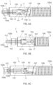
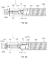
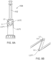
- Figs. 6A to 6E and 7A to 7D show the cylinder 102 having a stopper 109 fixed thereto, and where the piston 104 has a slot 111 in the form of a groove 111 for guiding the stopper 109 therein.
- the working principle of the second example embodiment of the PAV 1 in Figs. 6A to 6E and Figs. 7A to 7D are different from the working principle shown for the first example embodiment in that the groove 111 has a continuous path along the circumferential direction of the piston 104.
- the concept of the PAV 1 differs from the previously described embodiment in that the piston 104 of the PAV 1 can be arranged in alternating positions and hence allowing for continuous open and closed cycles.
- the PAV of the second example embodiment comprises a first spring 106 and a second spring 107 working in opposite directions, wherein the second spring 107 is a soft/less powerful spring compared to the first spring 106.
Landscapes
- Geology (AREA)
- Life Sciences & Earth Sciences (AREA)
- Engineering & Computer Science (AREA)
- Mining & Mineral Resources (AREA)
- Environmental & Geological Engineering (AREA)
- Fluid Mechanics (AREA)
- Physics & Mathematics (AREA)
- General Life Sciences & Earth Sciences (AREA)
- Geochemistry & Mineralogy (AREA)
- Actuator (AREA)
- Valves And Accessory Devices For Braking Systems (AREA)
- Yarns And Mechanical Finishing Of Yarns Or Ropes (AREA)
- Filling Or Discharging Of Gas Storage Vessels (AREA)
Claims (14)
- Druckaktiviertes Ventil (1) zum Verhindern, dass Fluid während Installation und Inbetriebnahme eines Förderrohrs (10) eines Bohrlochs durch eine Zuflusssteuervorrichtung (2) strömt, umfassend einen Zylinder (102), der sowohl an einem ersten als auch an einem zweiten Längsende (102a, 102b) offen ist,dadurch gekennzeichnet, dass das druckaktivierte Ventil Folgendes umfasst:- einen zylindrischen Kolben (104), der beweglich innerhalb des Zylinders (102) angeordnet ist, wobei der Kolben (104) hohl ist, wodurch Fluid ermöglicht wird, in einen ersten Längsendabschnitt (104a) einzutreten, und an einem zweiten Längsendabschnitt (104b) geschlossen ist, wodurch Fluid daran gehindert wird, dadurch zu fließen, wobei der Kolben (104) ferner mindestens eine radial angeordnete Öffnung (112), die zu dem zweiten Längsendabschnitt (104b) benachbart ist, umfasst,- eine Dichtung (113), die dazu angeordnet ist, mit dem Kolben (104) und dem Zylinder (102) zusammenzuwirken,wobei entweder der Zylinder (102) einen Schlitz (110) zum Aufnehmen und Führen eines Anschlags (108) umfasst, der an dem Kolben (104) befestigt ist, oder der Kolben (104) einen Schlitz (111) zum Aufnehmen und Führen eines Anschlags (109) umfasst, der an dem Zylinder (102) befestigt ist,wobei der Schlitz (110, 111) dazu konfiguriert ist, den Kolben (104) folgendermaßen zu führen:i) von einer ersten Position (P1), wobei der Kolben (104) durch eine Feder (106) in einer vorgespannten Position positioniert ist, wobei der Anschlag (108, 109) an ein erstes Ende (110a, 111a) des Schlitzes (110, 111) anstößt und wobei der Kolben (104) derart angeordnet ist, dass sich die mindestens eine radial angeordnete Öffnung (112) und Dichtung (113) innerhalb des Zylinders (102) befinden, wodurch ein beliebiges Fluid daran gehindert wird, durch das druckaktivierte Ventil (1) zu strömen;
in Richtungii) einer zweiten Position (P2) durch Zusammendrücken der Feder (106) aufgrund eines Innendrucks, der auf den Kolben (104) ausgeübt wird, wobei der Kolben (104) in einem zumindest teilweise spiralförmigen Weg in Richtung des ersten Längsendes (102a) des Zylinders (102) bewegt wird, bis der Anschlag (108, 109) an ein zweites Ende (110b, 111b) des Schlitzes (110, 111) anstößt;
und danach in Richtungiii) einer dritten Position (P3) durch Freigeben des Innendrucks, der auf den Kolben (104) ausgeübt wird, wobei der Kolben (104) in einem Weg in Richtung des zweiten Längsendes (102b) des Zylinders (102) bewegt wird, bis der Anschlag (108, 109) an ein drittes Ende (110c, 111c) des Schlitzes (110, 111) anstößt, sodass die Dichtung (113) ermöglicht, dass Fluid durch das PAV (1) hindurchfließt. - Druckaktiviertes Ventil (1) nach Anspruch 1, wobei der Zylinder (102) den Schlitz (110) umfasst und der Anschlag (108) an einer Außenfläche des Kolbens (104) befestigt ist.
- Druckaktiviertes Ventil (1) nach Anspruch 2, wobei der Zylinder (102) zwei identische Schlitze (110, 110') umfasst und der Kolben (104) zwei Anschläge (108, 108') umfasst, wobei die zwei identischen Schlitze (110, 110') und die zwei Anschläge (108, 108') jeweils auf gegenüberliegenden Seiten des Zylinders (102) und des Kolbens (104) angeordnet sind.
- Druckaktiviertes Ventil (1) nach Anspruch 1, wobei der Kolben (104) den Schlitz (111) umfasst und der Anschlag (109) an dem Zylinder (102) befestigt ist.
- Druckaktiviertes Ventil (1) nach einem der vorhergehenden Ansprüche, wobei die mindestens eine radial angeordnete Öffnung (112) eine einer länglichen, einer ovalen und einer rechteckigen Form mit gerundeten Ecken aufweist, die sich in einer Längsrichtung des Kolbens (104) erstreckt.
- Druckaktiviertes Ventil (1) nach einem der vorhergehenden Ansprüche, wobei mindestens eine radial angeordnete Öffnung (112) eine Längslänge aufweist, die sich von einem beliebigen von 5 % bis 60 % oder 10 % bis 50 % oder 10 % bis 40 % einer maximalen Längslänge des Kolbens (104) erstreckt.
- Druckaktiviertes Ventil (1) nach einem der vorhergehenden Ansprüche, wobei die mindestens eine radial angeordnete Öffnung (112) eine Umlaufserstreckung von einem beliebigen von 20° bis 90° oder 30° bis 80° oder 40° bis 70° aufweist.
- Druckaktiviertes Ventil (1) nach einem der vorhergehenden Ansprüche, wobei der Kolben (104) mindestens drei radial angeordnete Öffnungen (112) umfasst.
- Druckaktiviertes Ventil (1) nach einem der vorhergehenden Ansprüche, wobei der Kolben (104) eine kürzere Längslänge als der Zylinder (102) aufweist.
- Druckaktiviertes Ventil (1) nach einem der vorhergehenden Ansprüche, wobei der Kolben (104) die Dichtung umfasst, die umlaufend an dem zweiten Längsendabschnitt (104b) angeordnet ist, der den Kolben (104) abdichtend innerhalb des Zylinders (102) anordnet, wenn sich der Kolben (104) in oder zwischen der ersten Position (P1) und der zweiten Position (P2) befindet, wodurch ein beliebiges Fluid daran gehindert wird, durch das druckaktivierte Ventil (1) zu strömen.
- System zum Verhindern, dass Fluid während Installation und Inbetriebnahme eines Förderstrangs (10) in einem Bohrloch durch eine Zuflusssteuervorrichtung (2) fließt, wobei das System Folgendes umfasst:- einen Förderstrang (10) oder ein Förderstranggelenk,- eine Zuflusssteuervorrichtung (2), die innerhalb einer Wand des Förderstrangs (10) oder des Förderstranggelenks angeordnet ist,- ein druckaktiviertes Ventil (1) nach Anspruch 1, das außerhalb des Förderstrangs angeordnet und dazu konfiguriert ist, zu verhindern, dass Fluid aus einem Behälter in die Zuflusssteuervorrichtung (2) eintritt, wenn das druckaktivierte Ventil (1) geschlossen ist, und zu ermöglichen, dass Fluid aus dem Behälter eintritt, wenn das druckaktivierte Ventil (1) offen ist.
- System nach Anspruch 11, wobei die Zuflusssteuervorrichtung (2) eine autonome Zuflusssteuervorrichtung (2) ist.
- System nach Anspruch 11 oder 12, wobei das druckaktivierte Ventil (1) gemäß einem der Ansprüche 2 bis 10 ist.
- Verfahren zum Verhindern von Fluidstrom durch eine Zuflusssteuervorrichtung, die innerhalb einer Wand eines Förderstrangs (10) angeordnet ist, unter Verwendung eines druckaktivierten Ventils (1) gemäß dem System nach Anspruch 13, wobei das Verfahren die folgenden Schritte umfasst:- Installieren des Kolbens (104) des druckaktivierten Ventils (1) in einer geschlossenen ersten Position (P1), wobei der Kolben (104) einem Druck durch eine Federkraft eines festgelegten Werts ausgesetzt ist;- Ausüben eines Innendrucks über dem eingestellten Wert, wobei der Innendruck von dem Förderstrang (10) derart in Richtung des druckaktivierten Ventils (1) ausgeübt wird, dass sich der Kolben (104) in eine geschlossene zweite Position (P2) bewegt;- Freigeben des Innendrucks, der den Kolben (104) in eine offene, dritte Position (P3) drängt.
Applications Claiming Priority (2)
| Application Number | Priority Date | Filing Date | Title |
|---|---|---|---|
| NO20201163A NO346450B1 (en) | 2020-10-26 | 2020-10-26 | A pressure actuated valve for use during installation and commission of a production string |
| PCT/EP2021/079497 WO2022090132A1 (en) | 2020-10-26 | 2021-10-25 | A pressure actuated valve for use during installation and commission of a production string |
Publications (3)
| Publication Number | Publication Date |
|---|---|
| EP4232686A1 EP4232686A1 (de) | 2023-08-30 |
| EP4232686C0 EP4232686C0 (de) | 2024-07-10 |
| EP4232686B1 true EP4232686B1 (de) | 2024-07-10 |
Family
ID=73451197
Family Applications (1)
| Application Number | Title | Priority Date | Filing Date |
|---|---|---|---|
| EP21801056.9A Active EP4232686B1 (de) | 2020-10-26 | 2021-10-25 | Druckbetätigtes ventil zur verwendung während der installation und inbetriebnahme eines produktionsstranges |
Country Status (10)
| Country | Link |
|---|---|
| US (1) | US12320233B2 (de) |
| EP (1) | EP4232686B1 (de) |
| CN (1) | CN116348657A (de) |
| AU (1) | AU2021372646B2 (de) |
| CA (1) | CA3194000A1 (de) |
| CO (1) | CO2023004957A2 (de) |
| EC (1) | ECSP23038247A (de) |
| MX (1) | MX2023004823A (de) |
| NO (1) | NO346450B1 (de) |
| WO (1) | WO2022090132A1 (de) |
Families Citing this family (1)
| Publication number | Priority date | Publication date | Assignee | Title |
|---|---|---|---|---|
| NO20220698A1 (en) * | 2022-06-20 | 2023-12-21 | Inflowcontrol As | A system comprising a pressure actuated valve for use in injection wells |
Family Cites Families (13)
| Publication number | Priority date | Publication date | Assignee | Title |
|---|---|---|---|---|
| US6237693B1 (en) * | 1999-08-13 | 2001-05-29 | Camco International Inc. | Failsafe safety valve and method |
| US6644412B2 (en) * | 2001-04-25 | 2003-11-11 | Weatherford/Lamb, Inc. | Flow control apparatus for use in a wellbore |
| US6877566B2 (en) * | 2002-07-24 | 2005-04-12 | Richard Selinger | Method and apparatus for causing pressure variations in a wellbore |
| US8474535B2 (en) * | 2007-12-18 | 2013-07-02 | Halliburton Energy Services, Inc. | Well screen inflow control device with check valve flow controls |
| WO2011037914A2 (en) * | 2009-09-22 | 2011-03-31 | Schlumberger Canada Limited | Inflow control device and methods for using same |
| NO336835B1 (no) * | 2012-03-21 | 2015-11-16 | Inflowcontrol As | Et apparat og en fremgangsmåte for fluidstrømstyring |
| CN104246119A (zh) | 2012-04-18 | 2014-12-24 | 哈利伯顿能源服务公司 | 绕过流动控制装置的设备、系统和方法 |
| NO20120964A1 (no) * | 2012-08-27 | 2014-02-28 | Well Innovation As | Barriereventil for anvendelse sammen med kompletteringsutstyr i en brønn |
| WO2014149049A1 (en) | 2013-03-21 | 2014-09-25 | Halliburton Energy Services, Inc. | Tubing pressure operated downhole fluid flow control system |
| US10487602B2 (en) * | 2015-03-24 | 2019-11-26 | Halliburton Energy Services, Inc. | Hydraulic control of downhole tools |
| WO2020014254A1 (en) * | 2018-07-11 | 2020-01-16 | Superior Energy Services, Llc | Autonomous flow controller device |
| MY204933A (en) * | 2018-12-05 | 2024-09-23 | Halliburton Energy Services Inc | Multi-piston activation mechanism |
| US11774002B2 (en) * | 2020-04-17 | 2023-10-03 | Schlumberger Technology Corporation | Hydraulic trigger with locked spring force |
-
2020
- 2020-10-26 NO NO20201163A patent/NO346450B1/en unknown
-
2021
- 2021-10-25 CA CA3194000A patent/CA3194000A1/en active Pending
- 2021-10-25 WO PCT/EP2021/079497 patent/WO2022090132A1/en not_active Ceased
- 2021-10-25 MX MX2023004823A patent/MX2023004823A/es unknown
- 2021-10-25 EP EP21801056.9A patent/EP4232686B1/de active Active
- 2021-10-25 CN CN202180073081.6A patent/CN116348657A/zh active Pending
- 2021-10-25 US US18/033,074 patent/US12320233B2/en active Active
- 2021-10-25 AU AU2021372646A patent/AU2021372646B2/en active Active
-
2023
- 2023-04-20 CO CONC2023/0004957A patent/CO2023004957A2/es unknown
- 2023-05-23 EC ECSENADI202338247A patent/ECSP23038247A/es unknown
Also Published As
| Publication number | Publication date |
|---|---|
| CN116348657A (zh) | 2023-06-27 |
| US20230392474A1 (en) | 2023-12-07 |
| CA3194000A1 (en) | 2022-05-05 |
| US12320233B2 (en) | 2025-06-03 |
| EP4232686C0 (de) | 2024-07-10 |
| EP4232686A1 (de) | 2023-08-30 |
| AU2021372646B2 (en) | 2024-08-01 |
| ECSP23038247A (es) | 2023-06-30 |
| NO20201163A1 (en) | 2020-10-26 |
| MX2023004823A (es) | 2023-05-10 |
| CO2023004957A2 (es) | 2023-06-30 |
| WO2022090132A1 (en) | 2022-05-05 |
| NO346450B1 (en) | 2022-08-22 |
| AU2021372646A1 (en) | 2023-06-08 |
Similar Documents
| Publication | Publication Date | Title |
|---|---|---|
| US7926575B2 (en) | Hydraulic lockout device for pressure controlled well tools | |
| DE69531312T2 (de) | Vorrichtung im Bohrloch, die durch Ringraumdruck betätigt wird | |
| US5765641A (en) | Bidirectional disappearing plug | |
| US9188235B2 (en) | Plug counter, fracing system and method | |
| US4270610A (en) | Annulus pressure operated closure valve with improved power mandrel | |
| US4691779A (en) | Hydrostatic referenced safety-circulating valve | |
| RU2528157C2 (ru) | Скважинный шаровой клапан с двунаправленным уплотнением и механическим управлением | |
| EP2464815B1 (de) | Wiederholbares bohrlochbypassventil mit druckverformungsrest | |
| EP0088550A2 (de) | Testventil mit einer hydraulischer Feder | |
| US4311197A (en) | Annulus pressure operated closure valve with improved reverse circulation valve | |
| AU2013315765B2 (en) | Multi-piston hydrostatic setting tool with locking feature and pressure balanced pistons | |
| US20090071658A1 (en) | Valve | |
| US10060213B2 (en) | Residual pressure differential removal mechanism for a setting device for a subterranean tool | |
| WO2017223157A1 (en) | Downhole tool actuation system having indexing mechanism and method | |
| US11486228B2 (en) | Resettable toe valve | |
| CA2976368A1 (en) | Pressure insensitive counting toe sleeve | |
| EP4232686B1 (de) | Druckbetätigtes ventil zur verwendung während der installation und inbetriebnahme eines produktionsstranges | |
| EP0682169A2 (de) | Druckbetätigte Vorrichtung zur Verwendung in einem Hochdruckbohrloch | |
| US4445571A (en) | Circulation valve | |
| CA2496331C (en) | Seal assembly for a safety valve | |
| EP0020155A1 (de) | Ventil mit Betätigungsvorrichtung für Bohrlöcher | |
| US6955231B1 (en) | Tool for changing the drilling direction while drilling | |
| GB2574654A (en) | Downhole tool | |
| EP2609283B1 (de) | Durchpumpzirkulations- und/oder sicherheitszirkulationsventil | |
| EA047506B1 (ru) | Приводимый в действие давлением клапан для использования при монтаже и вводе в эксплуатацию эксплуатационной колонны |
Legal Events
| Date | Code | Title | Description |
|---|---|---|---|
| STAA | Information on the status of an ep patent application or granted ep patent |
Free format text: STATUS: UNKNOWN |
|
| STAA | Information on the status of an ep patent application or granted ep patent |
Free format text: STATUS: THE INTERNATIONAL PUBLICATION HAS BEEN MADE |
|
| PUAI | Public reference made under article 153(3) epc to a published international application that has entered the european phase |
Free format text: ORIGINAL CODE: 0009012 |
|
| STAA | Information on the status of an ep patent application or granted ep patent |
Free format text: STATUS: REQUEST FOR EXAMINATION WAS MADE |
|
| 17P | Request for examination filed |
Effective date: 20230508 |
|
| AK | Designated contracting states |
Kind code of ref document: A1 Designated state(s): AL AT BE BG CH CY CZ DE DK EE ES FI FR GB GR HR HU IE IS IT LI LT LU LV MC MK MT NL NO PL PT RO RS SE SI SK SM TR |
|
| DAV | Request for validation of the european patent (deleted) | ||
| DAX | Request for extension of the european patent (deleted) | ||
| GRAP | Despatch of communication of intention to grant a patent |
Free format text: ORIGINAL CODE: EPIDOSNIGR1 |
|
| STAA | Information on the status of an ep patent application or granted ep patent |
Free format text: STATUS: GRANT OF PATENT IS INTENDED |
|
| INTG | Intention to grant announced |
Effective date: 20240221 |
|
| GRAS | Grant fee paid |
Free format text: ORIGINAL CODE: EPIDOSNIGR3 |
|
| GRAA | (expected) grant |
Free format text: ORIGINAL CODE: 0009210 |
|
| STAA | Information on the status of an ep patent application or granted ep patent |
Free format text: STATUS: THE PATENT HAS BEEN GRANTED |
|
| AK | Designated contracting states |
Kind code of ref document: B1 Designated state(s): AL AT BE BG CH CY CZ DE DK EE ES FI FR GB GR HR HU IE IS IT LI LT LU LV MC MK MT NL NO PL PT RO RS SE SI SK SM TR |
|
| REG | Reference to a national code |
Ref country code: CH Ref legal event code: EP |
|
| REG | Reference to a national code |
Ref country code: DE Ref legal event code: R096 Ref document number: 602021015600 Country of ref document: DE |
|
| U01 | Request for unitary effect filed |
Effective date: 20240723 |
|
| U07 | Unitary effect registered |
Designated state(s): AT BE BG DE DK EE FI FR IT LT LU LV MT NL PT SE SI Effective date: 20240802 |
|
| U20 | Renewal fee for the european patent with unitary effect paid |
Year of fee payment: 4 Effective date: 20240911 |
|
| PG25 | Lapsed in a contracting state [announced via postgrant information from national office to epo] |
Ref country code: GR Free format text: LAPSE BECAUSE OF FAILURE TO SUBMIT A TRANSLATION OF THE DESCRIPTION OR TO PAY THE FEE WITHIN THE PRESCRIBED TIME-LIMIT Effective date: 20241011 Ref country code: PL Free format text: LAPSE BECAUSE OF FAILURE TO SUBMIT A TRANSLATION OF THE DESCRIPTION OR TO PAY THE FEE WITHIN THE PRESCRIBED TIME-LIMIT Effective date: 20240710 |
|
| PG25 | Lapsed in a contracting state [announced via postgrant information from national office to epo] |
Ref country code: IS Free format text: LAPSE BECAUSE OF FAILURE TO SUBMIT A TRANSLATION OF THE DESCRIPTION OR TO PAY THE FEE WITHIN THE PRESCRIBED TIME-LIMIT Effective date: 20241110 |
|
| PG25 | Lapsed in a contracting state [announced via postgrant information from national office to epo] |
Ref country code: HR Free format text: LAPSE BECAUSE OF FAILURE TO SUBMIT A TRANSLATION OF THE DESCRIPTION OR TO PAY THE FEE WITHIN THE PRESCRIBED TIME-LIMIT Effective date: 20240710 |
|
| PG25 | Lapsed in a contracting state [announced via postgrant information from national office to epo] |
Ref country code: ES Free format text: LAPSE BECAUSE OF FAILURE TO SUBMIT A TRANSLATION OF THE DESCRIPTION OR TO PAY THE FEE WITHIN THE PRESCRIBED TIME-LIMIT Effective date: 20240710 Ref country code: RS Free format text: LAPSE BECAUSE OF FAILURE TO SUBMIT A TRANSLATION OF THE DESCRIPTION OR TO PAY THE FEE WITHIN THE PRESCRIBED TIME-LIMIT Effective date: 20241010 |
|
| PG25 | Lapsed in a contracting state [announced via postgrant information from national office to epo] |
Ref country code: RS Free format text: LAPSE BECAUSE OF FAILURE TO SUBMIT A TRANSLATION OF THE DESCRIPTION OR TO PAY THE FEE WITHIN THE PRESCRIBED TIME-LIMIT Effective date: 20241010 Ref country code: PL Free format text: LAPSE BECAUSE OF FAILURE TO SUBMIT A TRANSLATION OF THE DESCRIPTION OR TO PAY THE FEE WITHIN THE PRESCRIBED TIME-LIMIT Effective date: 20240710 Ref country code: IS Free format text: LAPSE BECAUSE OF FAILURE TO SUBMIT A TRANSLATION OF THE DESCRIPTION OR TO PAY THE FEE WITHIN THE PRESCRIBED TIME-LIMIT Effective date: 20241110 Ref country code: HR Free format text: LAPSE BECAUSE OF FAILURE TO SUBMIT A TRANSLATION OF THE DESCRIPTION OR TO PAY THE FEE WITHIN THE PRESCRIBED TIME-LIMIT Effective date: 20240710 Ref country code: GR Free format text: LAPSE BECAUSE OF FAILURE TO SUBMIT A TRANSLATION OF THE DESCRIPTION OR TO PAY THE FEE WITHIN THE PRESCRIBED TIME-LIMIT Effective date: 20241011 Ref country code: ES Free format text: LAPSE BECAUSE OF FAILURE TO SUBMIT A TRANSLATION OF THE DESCRIPTION OR TO PAY THE FEE WITHIN THE PRESCRIBED TIME-LIMIT Effective date: 20240710 |
|
| PG25 | Lapsed in a contracting state [announced via postgrant information from national office to epo] |
Ref country code: SM Free format text: LAPSE BECAUSE OF FAILURE TO SUBMIT A TRANSLATION OF THE DESCRIPTION OR TO PAY THE FEE WITHIN THE PRESCRIBED TIME-LIMIT Effective date: 20240710 |
|
| PG25 | Lapsed in a contracting state [announced via postgrant information from national office to epo] |
Ref country code: CZ Free format text: LAPSE BECAUSE OF FAILURE TO SUBMIT A TRANSLATION OF THE DESCRIPTION OR TO PAY THE FEE WITHIN THE PRESCRIBED TIME-LIMIT Effective date: 20240710 |
|
| PG25 | Lapsed in a contracting state [announced via postgrant information from national office to epo] |
Ref country code: SK Free format text: LAPSE BECAUSE OF FAILURE TO SUBMIT A TRANSLATION OF THE DESCRIPTION OR TO PAY THE FEE WITHIN THE PRESCRIBED TIME-LIMIT Effective date: 20240710 |
|
| PLBE | No opposition filed within time limit |
Free format text: ORIGINAL CODE: 0009261 |
|
| STAA | Information on the status of an ep patent application or granted ep patent |
Free format text: STATUS: NO OPPOSITION FILED WITHIN TIME LIMIT |
|
| REG | Reference to a national code |
Ref country code: CH Ref legal event code: PL |
|
| 26N | No opposition filed |
Effective date: 20250411 |
|
| PG25 | Lapsed in a contracting state [announced via postgrant information from national office to epo] |
Ref country code: MC Free format text: LAPSE BECAUSE OF FAILURE TO SUBMIT A TRANSLATION OF THE DESCRIPTION OR TO PAY THE FEE WITHIN THE PRESCRIBED TIME-LIMIT Effective date: 20240710 |
|
| PG25 | Lapsed in a contracting state [announced via postgrant information from national office to epo] |
Ref country code: CH Free format text: LAPSE BECAUSE OF NON-PAYMENT OF DUE FEES Effective date: 20241031 |
|
| PGFP | Annual fee paid to national office [announced via postgrant information from national office to epo] |
Ref country code: NO Payment date: 20250730 Year of fee payment: 5 |
|
| PG25 | Lapsed in a contracting state [announced via postgrant information from national office to epo] |
Ref country code: IE Free format text: LAPSE BECAUSE OF NON-PAYMENT OF DUE FEES Effective date: 20241025 |
|
| U20 | Renewal fee for the european patent with unitary effect paid |
Year of fee payment: 5 Effective date: 20250912 |
|
| PG25 | Lapsed in a contracting state [announced via postgrant information from national office to epo] |
Ref country code: RO Free format text: LAPSE BECAUSE OF FAILURE TO SUBMIT A TRANSLATION OF THE DESCRIPTION OR TO PAY THE FEE WITHIN THE PRESCRIBED TIME-LIMIT Effective date: 20240710 |
|
| PGFP | Annual fee paid to national office [announced via postgrant information from national office to epo] |
Ref country code: GB Payment date: 20251013 Year of fee payment: 5 |
|
| PG25 | Lapsed in a contracting state [announced via postgrant information from national office to epo] |
Ref country code: CY Free format text: LAPSE BECAUSE OF FAILURE TO SUBMIT A TRANSLATION OF THE DESCRIPTION OR TO PAY THE FEE WITHIN THE PRESCRIBED TIME-LIMIT; INVALID AB INITIO Effective date: 20211025 |
|
| PG25 | Lapsed in a contracting state [announced via postgrant information from national office to epo] |
Ref country code: HU Free format text: LAPSE BECAUSE OF FAILURE TO SUBMIT A TRANSLATION OF THE DESCRIPTION OR TO PAY THE FEE WITHIN THE PRESCRIBED TIME-LIMIT; INVALID AB INITIO Effective date: 20211025 |