EP4232329B1 - Bremssystemmodul für einen anhänger - Google Patents
Bremssystemmodul für einen anhänger Download PDFInfo
- Publication number
- EP4232329B1 EP4232329B1 EP20799635.6A EP20799635A EP4232329B1 EP 4232329 B1 EP4232329 B1 EP 4232329B1 EP 20799635 A EP20799635 A EP 20799635A EP 4232329 B1 EP4232329 B1 EP 4232329B1
- Authority
- EP
- European Patent Office
- Prior art keywords
- pressure
- trailer
- port
- brake
- control
- Prior art date
- Legal status (The legal status is an assumption and is not a legal conclusion. Google has not performed a legal analysis and makes no representation as to the accuracy of the status listed.)
- Active
Links
Images


Classifications
-
- B—PERFORMING OPERATIONS; TRANSPORTING
- B60—VEHICLES IN GENERAL
- B60T—VEHICLE BRAKE CONTROL SYSTEMS OR PARTS THEREOF; BRAKE CONTROL SYSTEMS OR PARTS THEREOF, IN GENERAL; ARRANGEMENT OF BRAKING ELEMENTS ON VEHICLES IN GENERAL; PORTABLE DEVICES FOR PREVENTING UNWANTED MOVEMENT OF VEHICLES; VEHICLE MODIFICATIONS TO FACILITATE COOLING OF BRAKES
- B60T15/00—Construction arrangement, or operation of valves incorporated in power brake systems and not covered by groups B60T11/00 or B60T13/00
- B60T15/02—Application and release valves
- B60T15/18—Triple or other relay valves which allow step-wise application or release and which are actuated by brake-pipe pressure variation to connect brake cylinders or equivalent to compressed air or vacuum source or atmosphere
- B60T15/20—Triple or other relay valves which allow step-wise application or release and which are actuated by brake-pipe pressure variation to connect brake cylinders or equivalent to compressed air or vacuum source or atmosphere controlled by two fluid pressures
- B60T15/203—Trailer control valves
-
- B—PERFORMING OPERATIONS; TRANSPORTING
- B60—VEHICLES IN GENERAL
- B60T—VEHICLE BRAKE CONTROL SYSTEMS OR PARTS THEREOF; BRAKE CONTROL SYSTEMS OR PARTS THEREOF, IN GENERAL; ARRANGEMENT OF BRAKING ELEMENTS ON VEHICLES IN GENERAL; PORTABLE DEVICES FOR PREVENTING UNWANTED MOVEMENT OF VEHICLES; VEHICLE MODIFICATIONS TO FACILITATE COOLING OF BRAKES
- B60T13/00—Transmitting braking action from initiating means to ultimate brake actuator with power assistance or drive; Brake systems incorporating such transmitting means, e.g. air-pressure brake systems
- B60T13/10—Transmitting braking action from initiating means to ultimate brake actuator with power assistance or drive; Brake systems incorporating such transmitting means, e.g. air-pressure brake systems with fluid assistance, drive, or release
- B60T13/24—Transmitting braking action from initiating means to ultimate brake actuator with power assistance or drive; Brake systems incorporating such transmitting means, e.g. air-pressure brake systems with fluid assistance, drive, or release the fluid being gaseous
- B60T13/26—Compressed-air systems
- B60T13/261—Compressed-air systems systems with both indirect application and application by springs or weights and released by compressed air
- B60T13/263—Compressed-air systems systems with both indirect application and application by springs or weights and released by compressed air specially adapted for coupling with dependent systems, e.g. tractor-trailer systems
-
- B—PERFORMING OPERATIONS; TRANSPORTING
- B60—VEHICLES IN GENERAL
- B60T—VEHICLE BRAKE CONTROL SYSTEMS OR PARTS THEREOF; BRAKE CONTROL SYSTEMS OR PARTS THEREOF, IN GENERAL; ARRANGEMENT OF BRAKING ELEMENTS ON VEHICLES IN GENERAL; PORTABLE DEVICES FOR PREVENTING UNWANTED MOVEMENT OF VEHICLES; VEHICLE MODIFICATIONS TO FACILITATE COOLING OF BRAKES
- B60T13/00—Transmitting braking action from initiating means to ultimate brake actuator with power assistance or drive; Brake systems incorporating such transmitting means, e.g. air-pressure brake systems
- B60T13/10—Transmitting braking action from initiating means to ultimate brake actuator with power assistance or drive; Brake systems incorporating such transmitting means, e.g. air-pressure brake systems with fluid assistance, drive, or release
- B60T13/24—Transmitting braking action from initiating means to ultimate brake actuator with power assistance or drive; Brake systems incorporating such transmitting means, e.g. air-pressure brake systems with fluid assistance, drive, or release the fluid being gaseous
- B60T13/26—Compressed-air systems
- B60T13/261—Compressed-air systems systems with both indirect application and application by springs or weights and released by compressed air
- B60T13/265—Compressed-air systems systems with both indirect application and application by springs or weights and released by compressed air dependent systems, e.g. trailer systems
-
- B—PERFORMING OPERATIONS; TRANSPORTING
- B60—VEHICLES IN GENERAL
- B60T—VEHICLE BRAKE CONTROL SYSTEMS OR PARTS THEREOF; BRAKE CONTROL SYSTEMS OR PARTS THEREOF, IN GENERAL; ARRANGEMENT OF BRAKING ELEMENTS ON VEHICLES IN GENERAL; PORTABLE DEVICES FOR PREVENTING UNWANTED MOVEMENT OF VEHICLES; VEHICLE MODIFICATIONS TO FACILITATE COOLING OF BRAKES
- B60T13/00—Transmitting braking action from initiating means to ultimate brake actuator with power assistance or drive; Brake systems incorporating such transmitting means, e.g. air-pressure brake systems
- B60T13/10—Transmitting braking action from initiating means to ultimate brake actuator with power assistance or drive; Brake systems incorporating such transmitting means, e.g. air-pressure brake systems with fluid assistance, drive, or release
- B60T13/66—Electrical control in fluid-pressure brake systems
- B60T13/68—Electrical control in fluid-pressure brake systems by electrically-controlled valves
- B60T13/683—Electrical control in fluid-pressure brake systems by electrically-controlled valves in pneumatic systems or parts thereof
-
- B—PERFORMING OPERATIONS; TRANSPORTING
- B60—VEHICLES IN GENERAL
- B60T—VEHICLE BRAKE CONTROL SYSTEMS OR PARTS THEREOF; BRAKE CONTROL SYSTEMS OR PARTS THEREOF, IN GENERAL; ARRANGEMENT OF BRAKING ELEMENTS ON VEHICLES IN GENERAL; PORTABLE DEVICES FOR PREVENTING UNWANTED MOVEMENT OF VEHICLES; VEHICLE MODIFICATIONS TO FACILITATE COOLING OF BRAKES
- B60T15/00—Construction arrangement, or operation of valves incorporated in power brake systems and not covered by groups B60T11/00 or B60T13/00
- B60T15/02—Application and release valves
- B60T15/18—Triple or other relay valves which allow step-wise application or release and which are actuated by brake-pipe pressure variation to connect brake cylinders or equivalent to compressed air or vacuum source or atmosphere
- B60T15/181—Trailer control valves
-
- B—PERFORMING OPERATIONS; TRANSPORTING
- B60—VEHICLES IN GENERAL
- B60T—VEHICLE BRAKE CONTROL SYSTEMS OR PARTS THEREOF; BRAKE CONTROL SYSTEMS OR PARTS THEREOF, IN GENERAL; ARRANGEMENT OF BRAKING ELEMENTS ON VEHICLES IN GENERAL; PORTABLE DEVICES FOR PREVENTING UNWANTED MOVEMENT OF VEHICLES; VEHICLE MODIFICATIONS TO FACILITATE COOLING OF BRAKES
- B60T8/00—Arrangements for adjusting wheel-braking force to meet varying vehicular or ground-surface conditions, e.g. limiting or varying distribution of braking force
- B60T8/17—Using electrical or electronic regulation means to control braking
- B60T8/1701—Braking or traction control means specially adapted for particular types of vehicles
- B60T8/1708—Braking or traction control means specially adapted for particular types of vehicles for lorries or tractor-trailer combinations
Definitions
- the present invention relates to trailer brake control modules or trailer control valves.
- the present invention relates to a trailer control valve utilized in a modular brake control system of a towing vehicle.
- the trailer control valve can be operated using a pressurized air.
- the terms - towing vehicle, towed vehicle or trailer are repeatedly used in a variety of contexts.
- the term “towing vehicle” can refer to e.g., a truck, tractor or any other vehicle which includes a primary propulsion system e.g., an engine for moving the vehicle.
- the term “towed vehicle” can refer to a trailer, a semitrailer or any extension of the towing vehicle with at least a pair of wheels included in it.
- the existing conventional braking systems include a variety of techniques to manage the difference in deceleration rates between a towing vehicle and a trailer. This is necessary, for instance, to prevent over-braking and/or under-braking of the trailer in comparison to the towing vehicle.
- US4768840A discloses a vehicle braking control system which is provided for sensing the magnitude of the vehicle operator's demand for braking effort and for distributing the braking effort between the individually controllable vehicle brake sites to achieve balanced braking if relatively low braking effort demand is sensed and to achieve proportional braking if relatively high braking effort demand is sensed.
- a trailer brake control module for a towing vehicle facilitating braking of a towed vehicle or trailer.
- the trailer brake control module comprises a pressure supply port, a trailer control pressure port, a primary control port for receiving either directly or indirectly a control brake pressure for operating the trailer brake control module, wherein the primary control port receives the control brake pressure from a pneumatically operated pressure medium.
- the trailer brake control module further comprises a pneumatic control pressure line providing alternative control brake pressure for operating the trailer brake control module, wherein the pneumatic control pressure line receives the alternative control brake pressure from an electronically operated pressure medium, and a relay valve is activated using either the control brake pressure received at the primary control port, or the alternative control brake pressure from the pneumatic control pressure line, wherein on activating the relay valve, the pneumatic pressure received at the pressure supply port is connected to the trailer control pressure port, wherein the trailer brake control module is additionally provided with a braking rate (z) rebalancing unit so that the difference of the braking rate between said towing vehicle and said trailer is maintained within a permissible threshold range.
- a pneumatic control pressure line providing alternative control brake pressure for operating the trailer brake control module
- the pneumatic control pressure line receives the alternative control brake pressure from an electronically operated pressure medium
- a relay valve is activated using either the control brake pressure received at the primary control port, or the alternative control brake pressure from the pneumatic control pressure line, wherein on activating the relay valve, the pneumatic
- the presence of the braking rate rebalancing unit within the trailer brake control module enables the rebalancing of the difference in the individual braking rate enabled at the towing and towed vehicles. This rebalancing is necessary to prevent accidental effects during the application of brakes in the towing and towed vehicles such as jack-knifing.
- the braking rate (z) rebalancing unit can be or is an electronic unit or a mechanical unit (predominance valve) or an electromechanical valve unit explained in one or more aspects of the present invention as "electronically operated sub-unit (W, 304, 306)" in a trailer brake module (300a) or “mechanically operated sub-unit (PRV)” in a trailer brake module (300b or 300c).
- the trailer brake control module consists of the following ports: the primary control port, a parking brake control port, the pressure supply port, the trailer control pressure port, a trailer supply pressure port, and a pressure relief port at the housing of the trailer brake module.
- trailer brake control modules include one more port P41 which entails one more chamber for receiving the pressurized air from P41 and an additional control piston therein. Such components are rendered unnecessary with the trailer brake module consisting of the ports mentioned above thereby having a positive effect on the costs of the device.
- the trailer brake control module further comprises a double check or select-high valve for supplying one of the control brake pressure and the alterative control brake pressure depending on the magnitude of each of the brake pressures, wherein the brake pressure which has the higher magnitude is supplied to the relay valve.
- the double check valve directly contributes to the number of control pressure ports necessary for the trailer brake control module.
- the double check valve enables connecting the relay valve with the pressure of higher magnitude form either the control brake pressure received at the primary control port, or the alternative control brake pressure from the pneumatic control pressure line.
- said brake rate rebalancing unit includes a mechanically operated sub-unit which is either coaxially positioned in relation to a central axis (Y-Y') of the trailer brake control module or is positioned perpendicular to said central axis (Y-Y'), wherein said mechanically operated sub-unit is at least vertically above the relay valve and/or at the same horizontal level or above the horizontal level of the trailer control pressure port taking the central axis (Y-Y') as reference.
- the mechanically operated sub-unit enables arriving at a trailer brake control module which is hybrid in nature, in which said brake control module can work under an electronic control (e.g., via operating the solenoid valves), but on the other hand cannot or need not block out the pneumatic driver control using e.g., the mechanically operated sub-unit.
- the trailer brake control module further comprises a pneumatically controlled metering valve connecting the pressure supply port and a trailer supply pressure port, wherein said metering valve operates in namely, first and second positions, wherein in the first position, the metering valve connects the pressure supply port and the trailer supply pressure port through a throttled flow orifice, and wherein in the second position, the metering valve connects the pressure supply port and the trailer supply pressure port in an invariable and open manner such that the whole of the pneumatic pressure received at the pressure supply port is transmitted to the trailer supply pressure port.
- the pneumatically controlled metering valve is held in the second position with the help of at least partly pre-existing pressure in the trailer supply pressure port and/or a spring.
- the trailer brake control module of any one of the above embodiments further comprises a first electronically controlled solenoid valve whose inlet is connected to the pressure supply port and outlet is selectively connected to the relay valve, wherein said outlet supplies the alternative control brake pressure.
- the electronically controlled solenoid valve enables electronically implemented dynamic braking functions such as EBS (Electronic Brake System), ASR (Anti-Slip Regulation), ESP (Electronic Stability Program) and others while operating the trailer brake control module.
- the outlet of the first electronically controlled solenoid valve carrying the alternative control brake pressure is connected to a first inlet of the double check or select-high valve, wherein the double check or select-high valve enables the selective connection of the outlet with the relay valve, when the pressure supplied at the outlet is of higher magnitude than the pressure at the primary control port.
- the trailer brake control module in accordance with any one of the above embodiments, wherein the pressure at the trailer brake control port is measured using a Pulse Width Modulation (PWM) based pressure sensor.
- PWM Pulse Width Modulation
- the technical purpose and/or advantage of using the PWM based pressure sensor is to provide for "functional safety" according to ISO standard 26262.
- the trailer brake control module further comprises a first pneumatic control chamber to which the primary control port is connected. Furthermore, in the same or different embodiment, the trailer brake control module further comprises a first control piston separating the first pneumatic control chamber and an additional volume (AV), and wherein the first control piston integrally comprises a fluid flow path indirectly connecting the trailer control pressure port and the additional volume (AV).
- a pneumatic brake system comprising the trailer brake control module of any one of the above-mentioned embodiments.
- the system further comprises an electronic control unit connected to the trailer brake control module to perform brake functions with or without driver brake demand.
- the pneumatic brake system is disclosed, wherein the electronic control unit controls the trailer brake control module such that braking rate (z) rebalancing unit achieves the maintenance of the difference of the braking rate between said towing vehicle and said towed vehicle within said permissible threshold range.
- braking rate (z) rebalancing unit achieves the maintenance of the difference of the braking rate between said towing vehicle and said towed vehicle within said permissible threshold range.
- Fig. 1 shows an exemplary characteristic curve displaying a comparison of deliver pressure at port labeled "P22" of Y-Axis (the port is not shown in Fig. 1 , but see e.g., Fig. 2 or Figs. 3a and 3b for understanding) of an exemplary trailer control valve (not shown in Fig. 1 , but see e.g., Fig. 2 or Figs. 3a and 3b ) and a control pressure received at primary control port P42 (the port is not shown in Fig. 1 , but see e.g., Fig. 2 or Figs. 3a and 3b ) of the exemplary trailer control valve (not shown in Fig. 1 , but see e.g., Fig. 2 or Figs. 3a and 3b ).
- the pressure at P22 leads to a coupling head (see e.g., 312.2 in fig. 3a ) provided at the end of P22.
- the coupling head is connected to the pneumatic line which represents the control pressure that is required to operate a trailer brake system.
- Alternative term for coupling heads is 'glad hand', which is predominantly used in brake terminologies.
- the exemplary characteristic curve shown in Fig. 1 at a region 102 represents an increasingly disproportionate magnitude (or a slightly higher magnitude) of pressure recorded at port "P22" after approximately 0.5 bar (see X-axis of the curve) is achieved at port P42 (primary control port). As can be noticed, between e.g., 0.5 to 0.7 bar of pressure recorded at port P42, there is considerably surge in pressure at port P22.
- the point of deflection 103 in Fig. 1 can represent opening of a predominance valve within a trailer brake control module i.e., based on the settings in the predominance valve, the curve at region 101 can move left or right in comparison to the curve at 103, but nevertheless would maintain a slope of 45 degrees.
- One such example of the predominance valve is cited in the background section is e.g., known from US4264108A .
- the curve shown after region 102 i.e., in region 101 in Fig. 1 progresses almost proportionally.
- a 3 bar control input at e.g., port P42 can lead to a 2.7 or 3.6 bar output at port P22.
- This change in the output is referred to a "predominance" setting, which can be adjusted to be in a predetermined range today from e.g., -1 bar to +0,3bar.
- this type of change in predominance set is carried out after assembly of a trailer control valve or trailer brake module by a testing department before the product reaches a customer.
- the predominance valve in simple terms extends the volume of a chamber of the trailer control valve connected to port P22 using e.g., a spring-based check valve system.
- One of the reasons for providing this predominance valve in the pneumatic brake circuit is to enable achieving a balance in the braking rate between the towing vehicle and the towed vehicle.
- the desired braking rate of a vehicle and/or a trailer is dependent on a variety of factors such as size and its load carrying capacity, rolling resistance, .
- a value or a range of values cannot be explicitly mentioned as these are customized based on the type of the vehicle, its characteristics, and also the characteristics of trailer attached to it.
- these values and/or ranges may be influenced by the class of the vehicles generally characterized by the weight, laden or unladen. In any case, what is required for an understanding, it is vital to have the difference in the braking rate between the towed and towing vehicle within a desired range. There are however variety of means to achieve this.
- Fig. 2 shows a schematic diagram of a conventional trailer control valve 200.
- Conventional trailer control valve 200 shown in Fig. 2 includes ports P3, P11, P12, P22 P41, P42, P43, a first control valve 204, a conventional relay valve 202 and a conventional predominance valve CPRV. A brief explanation of conventional trailer control valve 200 is provided herewith.
- a supply pressure inlet P11 is shown which is typically connected to a pressurized fluid source (not shown in Fig. 2 ) such as a fluid reservoir.
- Supply pressure inlet P11 is connected to a trailer supply pressure outlet P12 which leads the output pressure to trailer brakes.
- a pneumatically controlled metering valve 204 is provided between supply pressure inlet P11 and trailer supply pressure outlet P12.
- Pneumatically controlled metering valve 204 operates for instance in two positions as shown in Fig. 1 . In the first position as shown in Fig. 2 in the current state, pneumatically controlled metering valve 204 connects supply pressure inlet P11 directly to trailer supply pressure outlet P12 without any metering i.e., with no pressure reduction.
- pneumatically controlled metering valve 204 may act as e.g., a throttled flow orifice wherein the supply pressure received at P11 is reduced before transmitting to trailer supply pressure outlet P12.
- metering valve 204 has two positions, one is fully open (full flow), and the second one is closed, smaller flow with an unspecified volume or flow rate.
- conventional trailer valve 200 includes relay valve 202 which needs to be activated by control pressure to enable a connection between the pressure provided from supply inlet P11 to a trailer control pressure outlet P22.
- control pressure can be derived from each of the ports: primary brake signal port P41, a primary control port P42, and a parking brake control port P43.
- relay valve 202 In non-activated position, relay valve 202 enables connection between P11 and pressure relief port P3. The relay valve 202, for instance, can be brought to the deactivated position when parking brake control port P43 is pressurized.
- one or more brake actuators at the wheel end of the vehicle are extended merely because of the force of one or more springs provided within the actuators. This is, however, part of a common general knowledge of the skilled person in the field of brake systems.
- conventional predominance valve CPRV is provided in association with trailer control pressure outlet P22 to enable the predominance characteristics such as the as shown in region 101 of Fig. 1 .
- This is merely shown for illustration of an additional volume connected to P22, but in practice the predominance valve may include a spring-based valve to let the pressure from port P22 into an extended volume it includes (see e.g., US patent publication 4264108 cited also above).
- Fig. 3a shows a schematic diagram of a trailer control valve or a trailer brake control module 300a in accordance with an embodiment of the present invention.
- trailer brake control module 300a is provided on a towing vehicle (not shown in Fig. 3a ) in order to facilitate braking of a towed vehicle or trailer.
- the trailer brake control module 300a comprises a pressure supply port or a supply pressure inlet P11, a trailer control pressure port or outlet P22, a primary control port P42 for receiving either directly and/or indirectly a control brake pressure for operating the trailer brake control module 300a.
- the primary control port P42 receives the control brake pressure from a pneumatically operated pressure medium (not shown).
- this pneumatically operated pressure medium can be a Brake Signal Transmitter (BST) or a Foot Brake Valve (FBV) or simply a valve that is directly connected to a brake pedal present at the driver's cabin.
- BST Brake Signal Transmitter
- BBV Foot Brake Valve
- the pressure received at port P42 reflects largely the driver's actual brake demand.
- the trailer brake control module 300a; 300b is additionally provided with braking rate 'z' rebalancing unit so that the difference of the braking rate between said towing vehicle and said trailer is maintained within a permissible threshold range, wherein in accordance with the present embodiment said brake rate rebalancing unit is enabled using an electronically operated sub-unit (W, 304, 306), and more particularly, said brake rate rebalancing unit is provided within a housing (406) of the trailer brake module (300b).
- brake control module 300a in this embodiment includes said electronically operated sub-unit.
- Said sub-unit may include a connection plug 'W' shown in Fig. 3a , a first solenoid valve 304, a second solenoid valve 306, and a pressure sensor 'X' (e.g., PWM based pressure sensor).
- at least connection plug 'W' may be connected to a centralized electronic brake module (not shown in Fig. 3a ) or an electronic control unit, which provides the requisite commands to operate or activate or deactivate e.g., first and second solenoid valves 304, 306 so as to enable maintenance of the braking rate difference between said towing vehicle and said trailer within the permissible threshold range.
- the predominance is electronically realized.
- One of the means of realizing this electronically is by the so-called CFC (coupling force control) function.
- said electronic control unit or the centralized electronic brake module may receive variety of inputs from sensors within the towing vehicle and the towed vehicle or trailer to determine what is the optimum braking performance that is required at any given time.
- the optimum braking performance is arrived at, such that the centralized electronic brake module or the electronic control unit within the trailer brake control module 300a can operate first and second solenoid vales 304 and 306 and effectively control e.g., operating frequency or cycles of said valves 304 and 306.
- the maintenance of e.g., the braking rate difference between said towing vehicle and said trailer within the permissible threshold range is possible to be performed dynamically.
- the braking rate (z) rebalancing unit is same as said electronically operated sub-unit.
- the electronically operated sub-unit is part of trailer brake control module 300a.
- trailer brake control module 300a vis-à-vis conventional trailer control valve or module 200 shown in Fig. 2 .
- the need for port P41 in module 300 is eliminated in comparison to trailer control valve or module 200 taking the overall construction of trailer brake control module 300a into account.
- the feature "the trailer brake control module 300a consists of the following ports: the primary control port (P42), a parking brake control port (P43), the pressure supply port (P11), the trailer control pressure port (P22), a trailer supply pressure port (P21), and a pressure relief port (P3) within a housing (406) of the trailer brake module)" is directed to denote absence of any additional control port.
- trailer brake control module 300a is additionally provided with a double check or select-high valve 308 for supplying one of the control brake pressure and the alterative control brake pressure depending on the magnitude of each of the brake pressures, wherein the brake pressure which has the higher magnitude is supplied to relay valve 310.
- double check valve 308 receives the control brake pressure from port P42 as marked in Fig. 3a .
- a second filter F2 is provided at the line connecting primary control port P42 and double check valve 308.
- double check valve 308 receives the alternative control brake pressure via solenoid valve 304 (depending on its respective position) and a first connection 308.1 to connect at least part of the pressure received from port P11.
- trailer brake control module 300a This allows for saving costs in overall construction of trailer brake control module 300a as it potentially replaces an electronically controlled solenoid valve in its place along with detecting pressure sensors at each of the connections from port P42 and connection 308.1 and thus, saves cost for a manufacturer of trailer brake modules. For a tier I manufacturer as the applicant/patentee, this results in reduction of costs depending on the scale and at the same time potentially saves time during the assembly.
- pneumatically controlled metering valve 302 operates in two positions, namely first and second positions, wherein in the first position, metering valve 302 connects pressure supply port P11 and the trailer supply pressure port P21 through a throttled flow orifice, and wherein in the second position, metering valve 302 connects pressure supply port P11 and trailer supply pressure port P21 in an invariable and open manner such that the whole of the pneumatic pressure received at pressure supply port P11 is transmitted to trailer supply pressure port P21.
- metering valve 302 includes a spring 302.3 which holds a piston or a spool in a predetermined position and the pressure from output port 308.2 determines the position of metering valve 302. Further, pneumatically controlled metering valve 302 is held in the second position with the help of at least partly because of the pre-existing pressure in trailer supply pressure port P21 and spring 302.3.
- trailer brake control module 300a includes first electronically controlled solenoid valve 304 whose inlet 304.1 is connected to pressure supply port P11 and outlet 304.2 is connected selectively to relay valve 310, wherein outlet 304.2 supplies the alternative control brake pressure.
- first electronically controlled solenoid valve 304 whose inlet 304.1 is connected to pressure supply port P11 and outlet 304.2 is connected selectively to relay valve 310, wherein outlet 304.2 supplies the alternative control brake pressure.
- the connection line which connects port P11 and inlet 304.1 includes a first filter F1 as can be derived from Fig. 3a in order to remove any moisture and/or impurities in the pressurized fluid.
- trailer brake control module 300a Overall functioning of trailer brake control module 300a is provided herewith.
- second electronically controlled solenoid valve 306 includes an inlet 306.1 and an outlet 306.2, wherein based on the position of second electronically controlled solenoid valve 306 a connection from outlet 306.2 to pressure relief port P3 is either established or prevented. They can be activated at varying frequency cycles such that a precise control over the pressure supplied to pneumatic control pressure line 308.1.
- the activation of said first and second solenoid valves 304 and 306 can either be driver initiated or automatically performed by the electronic control unit (not shown in Fig. 3a ) based on the braking requirements of the trailer including the dynamically changing braking rates and emergency braking conditions at any given time.
- the emergency braking conditions take into account of external and/or environmental factors such as surface and/or road conditions.
- the supply pressure that is received at port P11 is sent to pneumatic control pressure line 308.1.
- This brake pressure is referred in the present application as "alternative" control brake pressure.
- a control brake pressure is also received at primary control port P42 via a second pneumatic control pressure line 308.3.
- Both the control brake pressure and said alternative control brake pressure converge at double check valve 308, wherein whichever pressure line among 308.1 and 308.3 carries pressure with higher magnitude is fused with output port 308.2.
- the pressure from output port 308.2 is partly sent to relay valve 310 and partly sent to metering valve 302.
- the pressure exiting port P21 is connected to a first coupling head 312.1, which in turn is connected to a supply pressure line for trailer brakes. Typically coupling head 312.1 is red colored.
- the pressure exiting port P22 is connected to a second coupling head 312.2, which in turn leads to a control pressure line for controlling or operating the trailer brakes.
- pressure at line connected to port P22 is measured almost constantly using sensor 'X' referenced in Fig. 3a .
- This sensor 'X' of this particularly preferred embodiment is a PWM-based-pressure sensor or Pulse-Width-Modulation-based-pressure sensor.
- the usage of PWM-based-pressure sensor enables "functional safety" according to ISO standard 26262 of trailer control module 300a. Over the duration of usage of trailer control module 300a in a commercial vehicle, the usage of PWM based pressure sensor directly affects the average life cycle of batteries used in the commercial vehicle.
- Fig. 3b shows a schematic diagram of trailer control valve or trailer control module 300b in accordance with another embodiment of the present invention.
- trailer control module 300b additionally includes a mechanically operated sub-unit ⁇ 314' to establish the predominance or to maintain the brake rate difference between the towing vehicle and the trailer within a predetermined threshold in addition to or alternative to the electronically operated sub-unit (W, 304, 306).
- the elements that are same in Fig. 3b and Fig. 3a are marked with same reference signs. For the sake of simplicity, the explanation provided in relation to the elements with the same reference signs in Fig. 3b is not repeated.
- Fig. 3a is provided to illustrate that in accordance with an exemplary embodiment on how the braking rate (z) rebalancing unit operates, particularly when it is implemented or enabled using the electronically operated sub-unit (W, 304, 306) works.
- the electronically operated sub-unit e.g., 'W' may receive controls from a central electronic unit (such as 508 in Fig. 5 ) or trailer control module 300a or 300b may have an electronic control unit be mounted to a housing of said module.
- the brake rate rebalancing unit is enabled either optionally or additionally using a mechanically operated sub-unit 314 (which can alternatively be referred to as predominance valve) that is coaxially positioned in relation to the relay valve 310.
- a mechanically operated sub-unit 314 which can alternatively be referred to as predominance valve
- mechanically operated sub-unit 314 is present in the path that connects outlet 310.1 of relay valve 310 and trailer control pressure port P22. This has space-saving effect taking the overall construction of trailer brake control module 300b into account. Further details on this are provided in the explanation in relation to Fig. 4b .
- mechanically operated sub-unit ⁇ 314' that is symbolically shown in Fig. 3b to be in the path of port P22 as merely to represent an additional volume along the path.
- This additional volume may be selectively opened and/or closed using the pressure reaching port P22 the details of which will be explained in reference to Fig. 4b .
- this selective opening of mechanically operated sub-unit 314 causes the variation in pressure characteristics at between port P42 and P22 as displayed in Fig. 1 of the present application with reference sign "102".
- the initial spike in pressure at port P22 is due to closed status or non-opening of the predominance or additional volume of the mechanically operated sub-unit ⁇ 314'.
- this equalization of pressure magnitude at e.g., port P22 needs to be taken into account every time trailer brake control module 300b be operated and/or activated, wherein the predominance volume is selectively opened.
- trailer brake control module 300b combines the possibility of purely electronically controlling pressure characteristics at ports P22 and P42 to follow the trend of pressure magnitudes at the respective ports as displayed in e.g., Fig. 1 with an additional or optional mechanically operated sub-unit ⁇ 314' within trailer control module 300b.
- a mechanically operated sub-unit to selectively open predominance volume or to bring the pressure characteristics at ports P22 and P42 within desired range can still be achieved pneumatically.
- this mechanically operated sub-unit 314 and its threshold pressure to selectively open an additional volume (AV) or a predominance volume for pressure normalization at ports P22 and P42 can be calibrated to the overall brake system requirement before delivery to vehicle manufacturers.
- trailer brake control module 300b If necessary, entire mechanically operated sub-unit 314 within trailer brake control module 300b be disabled for purely electronic controlling to achieve the necessary pressure characteristics at ports P22 and P42 and vice-versa.
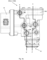
- Fig. 4a shows an external view of a trailer control valve or trailer brake control module 300a or 300b in accordance with an embodiment of the present invention.
- trailer brake control module 300a or 300b consists of the following ports: the primary control port (P42), a parking brake control port (P43), the pressure supply port (P11), the trailer control pressure port (P22), a trailer supply pressure port (P21), and a pressure relief port (P3) at housing 406 of trailer brake module 300a or 300b.
- the external view illustrates the spatial arrangement of ports P11, P21, P22, P42, P43, and P3 in accordance with an exemplary embodiment.
- 'W' in Fig. 4a shows the electronic connection point where wirings and other related components are enclosed.
- solenoid valves 304 and 306 of Figs. 3a and 3b are connected to the wirings provided within the section labeled as "W" in trailer brake control module 300a or 300b as shown in Fig. 4a .
- cross-sectional view displayed in Fig. 4b is from the plane A-A' whereas the cross-sectional view in Fig. 4c is from the plane B-B'.
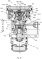
- Fig. 4b shows a cross-sectional view of a trailer control valve 300b in accordance with an embodiment of the present invention.
- trailer brake control module 300b further comprises a first pneumatic control chamber 402 to which primary control port P42 or pneumatic control pressure line 308.1 is connected.
- a first piston 404 moves linearly down along axis Y-Y' as shown in Fig. 4b .
- the downward direction in relation to axis Y-Y' is shown as 'D' in Fig. 4b .
- Relay piston 414 is configured to move in a fluid tight manner along axis Y-Y' within a housing 406 and is supported by relay spring 416.
- valve seat 310.1 of relay valve 310 is dislodged, thereby enabling a pressure connection between chamber marked as P11 and port P22.
- the direction of flow of air in case activating relay valve 310 is shown via arrow marks 'F' in Fig. 4b .
- predominance volume or additional volume within trailer brake control module 300b, as can be seen, it is provided coaxially with respect to relay valve 310 along axis Y-Y', but at the same time vertically above relay valve 310.
- Said predominance volume or additional volume AV is part of mechanically operated sub-unit 314 or predominance valve (PRV).
- PRV predominance valve
- the pressurized air On activating relay valve 310 by relay piston 414, the pressurized air enters chamber associated with P22 from P11 via the direction of flow shown as 'F'.
- the pressurized air enters predominance volume chamber 408.
- the connection between P22 and chamber 408 is not shown in the cross-section displayed in the present figure.
- a predominance valve piston 408.1 moves in downward direction along axis Y-Y'. After certain amount downward movement of piston 408.1, a plate valve 410 positioned concentrically with piston 408.1 hits an adjustment screw 412.
- adjustment screw 412 displaces or lifts plate valve 410 against a spring 408.2 located within chamber 408.
- plate valve 410 is not exactly circular in shape. The shape of plate valve 410 is only good enough to close a central bore 412.1 of adjustment screw 412. However, plate valve 410 is not in interference fit or flush with an inner diameter "D1" of piston 408.1 and there exists a gap between a lateral outer surface and inner diameter D1 of piston 408.1.
- the pressurized air from chamber 408 enters the additional volume or predominance volume AV.
- This volume is responsible for commensurate pressure reduction at port P22 and causes the change in pressure characteristics as shown in region 102 of Fig. 1 .
- the change in the pressure characteristics between ports P42 and P22 causes proportional change in the braking rate of the trailer or the towed vehicle for which the brake needs to be applied using trailer brake control module 300b.
- mechanically operated sub-unit (314) maintains the difference of the braking rate between the towing vehicle and the trailer within a permissible threshold range.
- mechanically operated sub-unit 314 is operated such that an initial pressure increase at trailer control pressure port P22 (shown at region 102 of Fig. 1 ) is accommodated by providing an additional volume AV within the trailer brake control module 300b.
- additional volume AV of predominance valve PRV is coaxially arranged, but vertically above relay valve 310 within trailer brake control module 300b.
- the wording "vertically above” can be understood in the present context with the help of disclosure in Fig. 4b along with arrow mark "U” denoting upward direction or what it means to be above in relation to relay valve 310.
- trailer brake control module 300b provides predominance valve PRV in addition to or alternative to the electronically controlled sub-unit of trailer brake control module 300a to enable maintaining the braking rate difference between the trailer and the towing vehicle.
- predominance valve PRV of trailer brake control module 300b is configured to operate independently from the electronically controlled sub-unit of trailer brake control module 300a while at the same time not disabling or disturbing the capability of the electronically controlled sub-unit to perform e.g., coupling force control (CFC) i.e., to keep the braking rate difference between the trailer and the towing vehicle within a threshold range.
- CFC coupling force control
- first control piston 404 separates first pneumatic control chamber 402 and additional volume (AV i.e., part of predominance valve PRV), and moreover first control piston 404 integrally comprises a fluid flow path 404.2 indirectly connecting trailer control pressure port P22 and additional volume (AV) through the above-explained mechanism.
- AV additional volume
- Fig. 4c shows a cross-sectional view of trailer control valve or trailer brake control module 300a or 300b in accordance with an embodiment of the present invention.
- trailer brake control module 300a or 300b displays the section of module as cut at plane B-B' of Fig. 4a .
- Fig. 4c The primary purpose of Fig. 4c is to show the spatial arrangement of ports P42, P11 and P21 along with the flow path 'F' of the pressurized fluid from port p11 towards P21. Furthermore, the structure and working of metering valve 302 as shown and explained also in conjunction with Figs. 3a and 3b is explained with the assistance of cross-sectional view of valve 302.
- valve 302 lies in the direct fluid path between ports P11 and P21.
- Valve 302 includes a linear piston 422 that can linearly reciprocate within a cylindrical chamber 426.
- Piston 422 is held a predetermined position using spring 302.3.
- Piston 422 is configured to operate in two positions as also explained before i.e., first and second positions.
- metering valve 302 In the first position, metering valve 302 connects pressure supply port P11 and trailer supply pressure port P21 through a throttled flow orifice 428, and wherein in the second position, metering valve 302 connects pressure supply port P11 and trailer supply pressure port P21 in an invariable and open manner such that the whole of the pneumatic pressure received at pressure supply port P11 is transmitted to trailer supply pressure port P21.
- Fig. 4c the displayed position is in the second position as shown in Figs. 3a and 3b as well. The pressurized fluid or air from P11 is directly sent without any metering to P21.
- a silencer 420 is provided at bottom portion of housing 406 that is configured to reduce the noise generated during the operation of trailer brake control module 300a or 300b. Silencer 420 is positioned at pressure relief port P3 of trailer brake control module 300a or 300b.
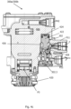
- Fig. 5 shows a cross-sectional view of a trailer brake control module 300c in accordance with another embodiment of the present invention.
- Fig. 5 shows arrangement of predominance valve PRV or mechanically operated sub-unit 314, which is positioned perpendicular to axix Y-Y' of trailer brake control module 300c. Furthermore, it is also realizable that predominance valve PRV is located vertically above a relay valve 516 of trailer brake module 300c. In order to show what is meant by "vertically above” - an arrow mark with reference “U” is shown in Fig. 5 . The general function of trailer brake control module 300b is explained herewith.
- First pneumatic control chamber 402 receives control pressure from port P42 (not shown in fig. 5 , but can be found in schematic representation of fig. 3a ).
- First relay piston 514 as shown in Fig. 5 , includes a stopper 520 inserted in a groove 522. Due to this downward movement of first relay piston 514, a second relay piston 524, which is functionally coupled to first relay piston 514 via stopper 520 also moves in the downward direction "D".
- second relay piston 524 includes an axial extension 526 which impinges on a top surface 526 of a valve seat 530 to move said valve seat 530 in downwards direction against a resisting force of a spring 530 within relay valve 516, thereby removing a closed contact at a contact zone 528 between valve seat 530 and a lateral extension 532 of a supply pressure receiving chamber 518. Due to this downward movement of valve seat 530, supply pressure receiving chamber 518, connected to port P11 (not shown in Fig. 5 , but refer to the schematic illustration in Fig. 3a or 3b ), now establishes a fluid connection with a control port pressure chamber V22. As shown in Fig. 5 , control port pressure chamber V22 is connected to port P22 on one side shown purely for illustrative reasons and is connected to predominance valve PRV on the other side.
- the pressurized air received at chamber V22 reaches an inlet 534 of predominance valve PRV, which is normally closed by a valve cap 510. If the pressure of the air reaching inlet 534 is higher than a threshold pressure that can overcome the resisting force of a spring 512 of predominance valve PRV, valve cap 510 is lifted and a fluid connection is established between chamber V22 and additional volume "AV" as shown in Fig. 5 with arrow mark "F” - a symbolic representation of fluid flow direction.
- “F” in Fig. 5 shows how the pressurized air starting from supply pressure receiving chamber 518 to V22 to inlet 534 to additional volume AV while at the same time reaching trailer control pressure port P22.
- valve 300c includes all the elements displayed in valve 300a in Fig. 3a and complies with the schematic layout displayed in Fig. 3b .
- vehicle 600 includes a pneumatic brake system 606, which in turn comprises trailer brake control module 300a or 300b or 300c of any one of the above-mentioned embodiments, and an electronic control unit 608 connected to trailer brake control module 300a or 300b or 300c to perform brake functions with or without driver brake demand.
- a pneumatic brake system 606 which in turn comprises trailer brake control module 300a or 300b or 300c of any one of the above-mentioned embodiments, and an electronic control unit 608 connected to trailer brake control module 300a or 300b or 300c to perform brake functions with or without driver brake demand.
- pneumatic brake system 606 of the present embodiment wherein electronic control unit 608 controls the electronically operated sub-unit (W, 304, 306) of trailer brake control module 300a such that braking rate (z) rebalancing unit achieves the maintenance of the difference of the braking rate between towing vehicle 602 and towed vehicle 604 within said permissible threshold range.
- electronic control unit 608 controls the electronically operated sub-unit (W, 304, 306) of trailer brake control module 300a such that braking rate (z) rebalancing unit achieves the maintenance of the difference of the braking rate between towing vehicle 602 and towed vehicle 604 within said permissible threshold range.
- This is achieved by obtaining the requisite pressure characteristics as illustrated above at ports P22 and P42 e.g., by electronically implemented operating technique through first and second solenoid valves 304 and 306.
Landscapes
- Engineering & Computer Science (AREA)
- Transportation (AREA)
- Mechanical Engineering (AREA)
- Physics & Mathematics (AREA)
- Fluid Mechanics (AREA)
- Regulating Braking Force (AREA)
- Valves And Accessory Devices For Braking Systems (AREA)
- Braking Systems And Boosters (AREA)
Claims (15)
- Anhängerbremssteuermodul (300a; 300b; 300c) für ein Zugfahrzeug (502), das das Bremsen eines gezogenen Fahrzeugs oder Anhängers (504) ermöglicht, umfassendeinen Druckversorgungsanschluss (P11);einen Anhängersteuerdruckanschluss (P22);einen Primärsteueranschluss (P42) zum direkten oder indirekten Erhalten eines Steuerbremsdrucks zum Betreiben des Anhängerbremssteuermoduls (300a; 300b; 300c), wobei der Primärsteueranschluss (P42) den Steuerbremsdruck von einem pneumatisch betriebenen Druckmedium erhält;eine Pneumatiksteuerdruckleitung (308.1), die einen alternativen Steuerbremsdruck zum Betreiben des Anhängerbremssteuermoduls (300a; 300b; 300c) bereitstellt, wobei die Pneumatiksteuerdruckleitung (308.1) den alternativen Steuerbremsdruck von einem elektronisch betriebenen Druckmedium erhält; undwobei ein Relaisventil (310; 516) aktiviert wird, unter Verwendung von entwederdem Steuerbremsdruck, der an dem Primärsteueranschluss (P42) erhalten wird, oderdem alternativen Steuerbremsdruck aus der Pneumatiksteuerdruckleitung (308.1),wobei beim Aktivieren des Relaisventils (310) der Pneumatikdruck, der an dem Druckversorgungsanschluss (P11) erhalten wird mit dem Anhängersteuerdruckanschluss (P22) verbunden wird,dadurch gekennzeichnet, dass das Anhängerbremssteuermodul (300a; 300b; 300c) zusätzlich mit einer Einheit zum Ausgleichen der Bremsrate (z) ausgestattet ist, sodass der Unterschied der Bremsrate zwischen dem Zugfahrzeug und dem Anhänger innerhalb eines zulässigen Schwellenbereichs gehalten wird.
- Anhängerbremssteuermodul (300a; 300b; 300c) nach Anspruch 1, wobei das Anhängerbremssteuermodul (300a; 300b; 300c) aus den folgenden Anschlüssen besteht:
dem Primärsteueranschluss (P42), einem Feststellbremsensteueranschluss (P43), dem Druckversorgungsanschluss (P11), dem Anhängersteuerdruckanschluss (P22), einem Anhängerversorgungsdruckanschluss (P21) und einem Druckentlastungsanschluss (P3) innerhalb eines Gehäuses (406) des Anhängerbremsmoduls (300b; 300c). - Anhängerbremssteuermodul (300a; 300b; 300c) nach Anspruch 1 oder 2, wobei das Anhängerbremssteuermodul (300a; 300b; 300c) ferner ein Doppelrückschlag- oder Select-High-Ventil (308) zum Zuführen von einem des Steuerbremsdrucks und des alternativen Steuerbremsdrucks in Abhängigkeit von der Stärke jedes der Bremsdrücke umfasst, wobei der Bremsdruck, der die höhere Stärke aufweist, dem Relaisventil (310) zugeführt wird.
- Anhängerbremssteuermodul (300a; 300b; 300c) nach Anspruch 1, wobei die Einheit zum Ausgleichen der Bremsrate eine mechanisch betätigte Teileinheit (314 oder PRV) einschließt, die entweder im Verhältnis zu einer Mittelachse (Y-Y') des Anhängerbremssteuermoduls (300a; 300b; 300c) koaxial positioniert ist, oder senkrecht zu der Mittelachse (Y-Y') positioniert ist, wobei die mechanisch betätigte Teileinheit (314 oder PRV) mindestens vertikal über dem Relaisventil (310; 516) ist.
- Anhängerbremssteuermodul (300a; 300b; 300c) nach Anspruch 1, wobei das Anhängerbremssteuermodul (300a; 300b; 300c) ferner ein pneumatisch gesteuertes Dosierventil (302) umfasst, das den Druckversorgungsanschluss (P11) und einen Anhängerversorgungsdruckanschluss (P21) verbindet, wobei das Dosierventil (302) insbesondere in einer ersten und einer zweiten Position arbeitet, wobei das Dosierventil (302) in der ersten Position den Druckversorgungsanschluss (P11) und den Anhängerversorgungsdruckanschluss (P21) durch eine gedrosselte Durchflussöffnung verbindet, und wobei das Dosierventil (302) in der zweiten Position den Druckversorgungsanschluss (P11) und den Anhängerversorgungsdruckanschluss (P21) in einer unveränderlichen und offenen Weise derart verbindet, dass der gesamte Pneumatikdruck, der an dem Druckversorgungsanschluss (P11) empfangen wird, an den Anhängerversorgungsdruckanschluss (P21) übertragen wird.
- Anhängerbremssteuermodul (300a; 300b; 300c) nach Anspruch 5, wobei das pneumatisch gesteuerte Dosierventil (302) in der zweiten Position mit Hilfe des mindestens teilweise bereits bestehenden Drucks in dem Anhängerversorgungsdruckanschluss (P21) und einer Feder (302.3) gehalten wird.
- Anhängerbremssteuermodul (300a; 300b; 300c) nach einem der vorstehenden Ansprüche, ferner umfassend ein erstes elektronisch gesteuertes Magnetventil (304), dessen Einlass (304.1) mit dem Druckversorgungsanschluss (P11) verbunden ist und dessen Auslass (304.2) mit dem Relaisventil (310) selektiv verbunden ist, wobei der Auslass (304.2) den alternativen Steuerbremsdruck zuführt.
- Anhängerbremssteuermodul (300a; 300b; 300c) nach den Ansprüchen 3 und 7, wobei der Auslass (304.2), der den alternativen Steuerbremsdruck führt, mit einem ersten Einlass (308.1) des Doppelrückschlag- oder Select-High-Ventils (308) verbunden ist, wobei das Doppelrückschlag- oder Select-High-Ventil (308) die selektive Verbindung des Auslasses (304.2) mit dem Relaisventil (310) ermöglicht, wenn der Druck, der an dem Auslass (304.2) zugeführt wird, höher als der Druck an dem Primärsteueranschluss (P42) ist.
- Anhängerbremssteuermodul (300a; 300b; 300c) nach einem der obigen Ansprüche, wobei die Größe des Drucks, der an dem Primärsteueranschluss (P42) empfangen wird, proportional zu der Bremsanforderung des Fahrers ist.
- Anhängerbremssteuermodul (300a; 300b; 300c) nach einem der obigen Ansprüche, wobei der Druck an dem Anhängerbremssteueranschluss (P22) unter Verwendung eines auf Pulsweitenmodulation (PWM) basierenden Drucksensors gemessen wird.
- Anhängerbremssteuermodul (300a; 300b; 300c) nach einem der obigen Ansprüche, wobei das Anhängerbremssteuermodul (300a; 300b; 300c) ferner eine erste Pneumatiksteuerkammer (402) umfasst, mit der der Primärsteueranschluss (P42) verbunden ist.
- Anhängerbremssteuermodul (300b; 300c) nach den Ansprüchen 10 und 11, wobei das Anhängerbremssteuermodul (300b; 300c) ferner einen ersten Steuerkolben (404) umfasst, der die erste Pneumatiksteuerkammer (402) und das zusätzliche Volumen (AV) trennt, und wobei der erste Steuerkolben (404) einen Fluiddurchflusspfad (404.2) integral umfasst, der den Anhängersteuerdruckanschluss (P22) und das zusätzliche Volumen (AV) indirekt verbindet.
- Pneumatikbremssystem (606), umfassend das Anhängerbremssteuermodul (300a; 300b; 300c) nach einem der oben genannten Ansprüche und eine elektronische Steuereinheit (608), die mit dem Anhängerbremssteuermodul (300a; 300b; 300c) verbunden ist, um Bremsfunktionen mit oder ohne Bremsanforderung des Fahrers durchzuführen.
- Pneumatikbremssystem (606) nach Anspruch 13, wobei die elektronische Steuereinheit (608) das Anhängerbremssteuermodul (300a; 300b; 300c) derart steuert, dass die Einheit zum Ausgleichen der Bremsrate (z) es schafft, den Unterschied der Bremsrate zwischen dem Zugfahrzeug (602) und dem gezogenen Fahrzeug (604) innerhalb des zulässigen Schwellenbereichs zu halten.
- Nutzfahrzeug oder ein autonomes Fahrzeug (600), umfassend das Pneumatikbremssystem nach Anspruch 14.
Applications Claiming Priority (1)
| Application Number | Priority Date | Filing Date | Title |
|---|---|---|---|
| PCT/EP2020/079556 WO2022083855A1 (en) | 2020-10-21 | 2020-10-21 | A trailer brake control module |
Publications (2)
| Publication Number | Publication Date |
|---|---|
| EP4232329A1 EP4232329A1 (de) | 2023-08-30 |
| EP4232329B1 true EP4232329B1 (de) | 2025-02-26 |
Family
ID=73037934
Family Applications (1)
| Application Number | Title | Priority Date | Filing Date |
|---|---|---|---|
| EP20799635.6A Active EP4232329B1 (de) | 2020-10-21 | 2020-10-21 | Bremssystemmodul für einen anhänger |
Country Status (4)
| Country | Link |
|---|---|
| US (1) | US12409826B2 (de) |
| EP (1) | EP4232329B1 (de) |
| CN (1) | CN116601060B (de) |
| WO (1) | WO2022083855A1 (de) |
Citations (6)
| Publication number | Priority date | Publication date | Assignee | Title |
|---|---|---|---|---|
| DE3431674A1 (de) | 1984-08-29 | 1986-03-13 | Robert Bosch Gmbh, 7000 Stuttgart | Anhaengersteuerventil |
| US4768840A (en) | 1987-04-27 | 1988-09-06 | Eaton Corporation | Brake control system and method |
| DE3901270A1 (de) | 1989-01-18 | 1990-07-19 | Bosch Gmbh Robert | Druckluftbremseinrichtung fuer kraftfahrzeuge |
| EP3533673A1 (de) | 2018-03-03 | 2019-09-04 | WABCO GmbH | Verfahren zur bremssteuerung eines fahrzeugzuges sowie derart betreibbarer fahrzeugzug |
| US20200047730A1 (en) | 2017-03-21 | 2020-02-13 | Wabco Gmbh | Integrated trailer control module with external electro-pneumatic parking brake unit |
| DE102018122193A1 (de) | 2018-09-12 | 2020-03-12 | Wabco Gmbh | Relaisventilmodul zur Verwendung als Achsmodulator und Anhängersteuermodul |
Family Cites Families (16)
| Publication number | Priority date | Publication date | Assignee | Title |
|---|---|---|---|---|
| IT1087801B (it) | 1977-10-28 | 1985-06-04 | Magneti Marelli Spa | Procedimento e relativo dispositivo per la frenatura pneumatica di predominanza di veicoli rimorchiati in genere |
| US4804234A (en) * | 1987-04-27 | 1989-02-14 | Eaton Corporation | Tractor-trailer brake control system |
| US4818035A (en) * | 1987-04-27 | 1989-04-04 | Eaton Corporation | Tractor-trailer brake control system |
| JP2007182106A (ja) * | 2006-01-05 | 2007-07-19 | Hitachi Ltd | ブレーキ制御装置およびその制御方法 |
| DE102006036748A1 (de) * | 2006-08-05 | 2008-02-07 | Wabco Gmbh | Elektrisch gesteuerte Bremsanlage |
| DE102014002614A1 (de) * | 2014-02-27 | 2015-08-27 | Wabco Gmbh | Bremsmodul für ein hydraulisch gebremstes Zugfahrzeug, welches mit einem pneumatisch gebremsten Anhängefahrzeug koppelbar ist. |
| CN104044571B (zh) * | 2014-07-02 | 2016-08-24 | 江苏大学 | 一种汽车列车联合制动系统及方法 |
| DE102015015922A1 (de) * | 2015-12-09 | 2017-06-14 | Wabco Gmbh | Verfahren zum Einstellen von Bremsdrücken an pneumatisch betätigten Radbremsen eines Fahrzeugs, Bremsanlage zur Durchführung des Verfahrens sowie Fahrzeug |
| DE102017002716A1 (de) | 2017-03-21 | 2018-09-27 | Wabco Gmbh | Elektronisch steuerbares Bremssystem sowie Verfahren zum Steuern des elektronisch steuerbaren Bremssystems |
| DE102017006356A1 (de) | 2017-03-21 | 2018-09-27 | Wabco Gmbh | Elektro-Pneumatische Handbremse (EPH) mit integriertem TCV (Europäische Ansteuerung) |
| DE102017005979A1 (de) | 2017-03-21 | 2018-09-27 | Wabco Gmbh | Elektro-Pneumatische Handbremse (EPH) mit integrierten TCV (skandinavische Ansteuerung |
| DE102018123750A1 (de) | 2018-09-14 | 2020-03-19 | Wabco Gmbh | Elektropneumatische Anhängersteuerventileinheit für Nordamerika |
| US10780871B2 (en) | 2018-09-26 | 2020-09-22 | Bendix Commercial Vehicle Systems Llc | Apparatus and method for controlling pneumatic fluid to a trailer |
| DE102018127813A1 (de) | 2018-11-07 | 2020-05-07 | Wabco Gmbh | Verfahren zur Funktionsüberprüfung eines druckmittelbetriebenen elektronischen Bremssystems eines Fahrzeugs |
| DE102019100869A1 (de) * | 2019-01-15 | 2020-07-16 | Wabco Gmbh | Ventilanordnung eines hydraulisch gebremsten Zugfahrzeugs zur Steuerung des Bremsdruckes eines pneumatisch gebremsten Anhängerfahrzeugs |
| IT201900005228A1 (it) * | 2019-04-05 | 2020-10-05 | Cnh Ind Italia Spa | Valvola di sicurezza migliorata per circuito di frenata idraulico |
-
2020
- 2020-10-21 WO PCT/EP2020/079556 patent/WO2022083855A1/en not_active Ceased
- 2020-10-21 CN CN202080105085.3A patent/CN116601060B/zh active Active
- 2020-10-21 US US18/032,575 patent/US12409826B2/en active Active
- 2020-10-21 EP EP20799635.6A patent/EP4232329B1/de active Active
Patent Citations (6)
| Publication number | Priority date | Publication date | Assignee | Title |
|---|---|---|---|---|
| DE3431674A1 (de) | 1984-08-29 | 1986-03-13 | Robert Bosch Gmbh, 7000 Stuttgart | Anhaengersteuerventil |
| US4768840A (en) | 1987-04-27 | 1988-09-06 | Eaton Corporation | Brake control system and method |
| DE3901270A1 (de) | 1989-01-18 | 1990-07-19 | Bosch Gmbh Robert | Druckluftbremseinrichtung fuer kraftfahrzeuge |
| US20200047730A1 (en) | 2017-03-21 | 2020-02-13 | Wabco Gmbh | Integrated trailer control module with external electro-pneumatic parking brake unit |
| EP3533673A1 (de) | 2018-03-03 | 2019-09-04 | WABCO GmbH | Verfahren zur bremssteuerung eines fahrzeugzuges sowie derart betreibbarer fahrzeugzug |
| DE102018122193A1 (de) | 2018-09-12 | 2020-03-12 | Wabco Gmbh | Relaisventilmodul zur Verwendung als Achsmodulator und Anhängersteuermodul |
Also Published As
| Publication number | Publication date |
|---|---|
| CN116601060B (zh) | 2025-12-09 |
| CN116601060A (zh) | 2023-08-15 |
| US12409826B2 (en) | 2025-09-09 |
| US20230398973A1 (en) | 2023-12-14 |
| WO2022083855A1 (en) | 2022-04-28 |
| EP4232329A1 (de) | 2023-08-30 |
Similar Documents
| Publication | Publication Date | Title |
|---|---|---|
| US5443306A (en) | Electrohydraulic brake control system | |
| US8282173B2 (en) | Electropneumatic parking brake modulator | |
| CN106458195B (zh) | 电-气驻车制动控制装置 | |
| CN108290563B (zh) | 具有附加控制回路的车辆电子气动式驻车制动装置 | |
| EP1509415B1 (de) | Integrierte steuereinheit für eine aktive rollregelung eines kraftfahrzeugaufhängungssystems | |
| US5042883A (en) | Trailer braking system for a towing vehicle | |
| CN100422008C (zh) | 横向动稳性控制系统 | |
| CN101331042B (zh) | 电空制动控制装置 | |
| US4585278A (en) | Brake system for vehicle combinations | |
| US11479225B2 (en) | Heavy duty vehicle redundant braking system | |
| JP2019514770A (ja) | 商用車の電子制御可能なエアブレーキシステム及びエアブレーキシステムを電子制御するための方法 | |
| EP2750945B1 (de) | Bremssystem für ein fahrzeug | |
| JPH06156259A (ja) | ブレーキシステム | |
| CN101312864A (zh) | 电气动制动控制装置 | |
| EP0837806B1 (de) | Bremsanlage für anhänger und ein ventil zur anwendung darin | |
| GB2161228A (en) | Hydraulic brake system | |
| CN112533805B (zh) | 具有关断阀的电气动的停驻制动设施以及用于对受电子控制的气动制动系统进行控制的方法 | |
| TR201818985T4 (tr) | Bir çekici aracın fren düzeneği ve fren düzenekleri grubu. | |
| US6644758B1 (en) | Automotive braking system actuated by a pressure fluid | |
| EP4232329B1 (de) | Bremssystemmodul für einen anhänger | |
| JPH04300765A (ja) | 2回路ブレーキ装置 | |
| US8191975B2 (en) | Single channel roll stability system | |
| US20210129810A1 (en) | Trailer detection and control module | |
| JPH03125657A (ja) | 自動車のためのブレーキ装置 | |
| IE54915B1 (en) | Improvements in anti-skid brake control systems |
Legal Events
| Date | Code | Title | Description |
|---|---|---|---|
| STAA | Information on the status of an ep patent application or granted ep patent |
Free format text: STATUS: UNKNOWN |
|
| STAA | Information on the status of an ep patent application or granted ep patent |
Free format text: STATUS: THE INTERNATIONAL PUBLICATION HAS BEEN MADE |
|
| PUAI | Public reference made under article 153(3) epc to a published international application that has entered the european phase |
Free format text: ORIGINAL CODE: 0009012 |
|
| STAA | Information on the status of an ep patent application or granted ep patent |
Free format text: STATUS: REQUEST FOR EXAMINATION WAS MADE |
|
| 17P | Request for examination filed |
Effective date: 20230522 |
|
| AK | Designated contracting states |
Kind code of ref document: A1 Designated state(s): AL AT BE BG CH CY CZ DE DK EE ES FI FR GB GR HR HU IE IS IT LI LT LU LV MC MK MT NL NO PL PT RO RS SE SI SK SM TR |
|
| DAV | Request for validation of the european patent (deleted) | ||
| DAX | Request for extension of the european patent (deleted) | ||
| GRAP | Despatch of communication of intention to grant a patent |
Free format text: ORIGINAL CODE: EPIDOSNIGR1 |
|
| STAA | Information on the status of an ep patent application or granted ep patent |
Free format text: STATUS: GRANT OF PATENT IS INTENDED |
|
| INTG | Intention to grant announced |
Effective date: 20241112 |
|
| RIN1 | Information on inventor provided before grant (corrected) |
Inventor name: TOMA, LESZEK Inventor name: SWIATEK, PAWEL Inventor name: RIEDIGER-JANISCH, KARL-HEINZ Inventor name: OTREMBA, ROBERT Inventor name: DRELICH, LUKASZ Inventor name: COUPPEE, ULRICH |
|
| GRAS | Grant fee paid |
Free format text: ORIGINAL CODE: EPIDOSNIGR3 |
|
| GRAA | (expected) grant |
Free format text: ORIGINAL CODE: 0009210 |
|
| STAA | Information on the status of an ep patent application or granted ep patent |
Free format text: STATUS: THE PATENT HAS BEEN GRANTED |
|
| AK | Designated contracting states |
Kind code of ref document: B1 Designated state(s): AL AT BE BG CH CY CZ DE DK EE ES FI FR GB GR HR HU IE IS IT LI LT LU LV MC MK MT NL NO PL PT RO RS SE SI SK SM TR |
|
| REG | Reference to a national code |
Ref country code: GB Ref legal event code: FG4D |
|
| REG | Reference to a national code |
Ref country code: CH Ref legal event code: EP |
|
| REG | Reference to a national code |
Ref country code: DE Ref legal event code: R096 Ref document number: 602020046855 Country of ref document: DE |
|
| REG | Reference to a national code |
Ref country code: IE Ref legal event code: FG4D |
|
| REG | Reference to a national code |
Ref country code: SE Ref legal event code: TRGR |
|
| REG | Reference to a national code |
Ref country code: NL Ref legal event code: MP Effective date: 20250226 |
|
| PG25 | Lapsed in a contracting state [announced via postgrant information from national office to epo] |
Ref country code: RS Free format text: LAPSE BECAUSE OF FAILURE TO SUBMIT A TRANSLATION OF THE DESCRIPTION OR TO PAY THE FEE WITHIN THE PRESCRIBED TIME-LIMIT Effective date: 20250526 |
|
| PG25 | Lapsed in a contracting state [announced via postgrant information from national office to epo] |
Ref country code: FI Free format text: LAPSE BECAUSE OF FAILURE TO SUBMIT A TRANSLATION OF THE DESCRIPTION OR TO PAY THE FEE WITHIN THE PRESCRIBED TIME-LIMIT Effective date: 20250226 |
|
| PG25 | Lapsed in a contracting state [announced via postgrant information from national office to epo] |
Ref country code: PL Free format text: LAPSE BECAUSE OF FAILURE TO SUBMIT A TRANSLATION OF THE DESCRIPTION OR TO PAY THE FEE WITHIN THE PRESCRIBED TIME-LIMIT Effective date: 20250226 |
|
| PG25 | Lapsed in a contracting state [announced via postgrant information from national office to epo] |
Ref country code: ES Free format text: LAPSE BECAUSE OF FAILURE TO SUBMIT A TRANSLATION OF THE DESCRIPTION OR TO PAY THE FEE WITHIN THE PRESCRIBED TIME-LIMIT Effective date: 20250226 |
|
| REG | Reference to a national code |
Ref country code: LT Ref legal event code: MG9D |
|
| PG25 | Lapsed in a contracting state [announced via postgrant information from national office to epo] |
Ref country code: NO Free format text: LAPSE BECAUSE OF FAILURE TO SUBMIT A TRANSLATION OF THE DESCRIPTION OR TO PAY THE FEE WITHIN THE PRESCRIBED TIME-LIMIT Effective date: 20250526 Ref country code: IS Free format text: LAPSE BECAUSE OF FAILURE TO SUBMIT A TRANSLATION OF THE DESCRIPTION OR TO PAY THE FEE WITHIN THE PRESCRIBED TIME-LIMIT Effective date: 20250626 |
|
| PG25 | Lapsed in a contracting state [announced via postgrant information from national office to epo] |
Ref country code: NL Free format text: LAPSE BECAUSE OF FAILURE TO SUBMIT A TRANSLATION OF THE DESCRIPTION OR TO PAY THE FEE WITHIN THE PRESCRIBED TIME-LIMIT Effective date: 20250226 |
|
| PG25 | Lapsed in a contracting state [announced via postgrant information from national office to epo] |
Ref country code: HR Free format text: LAPSE BECAUSE OF FAILURE TO SUBMIT A TRANSLATION OF THE DESCRIPTION OR TO PAY THE FEE WITHIN THE PRESCRIBED TIME-LIMIT Effective date: 20250226 |
|
| PG25 | Lapsed in a contracting state [announced via postgrant information from national office to epo] |
Ref country code: LV Free format text: LAPSE BECAUSE OF FAILURE TO SUBMIT A TRANSLATION OF THE DESCRIPTION OR TO PAY THE FEE WITHIN THE PRESCRIBED TIME-LIMIT Effective date: 20250226 Ref country code: PT Free format text: LAPSE BECAUSE OF FAILURE TO SUBMIT A TRANSLATION OF THE DESCRIPTION OR TO PAY THE FEE WITHIN THE PRESCRIBED TIME-LIMIT Effective date: 20250626 |
|
| PG25 | Lapsed in a contracting state [announced via postgrant information from national office to epo] |
Ref country code: GR Free format text: LAPSE BECAUSE OF FAILURE TO SUBMIT A TRANSLATION OF THE DESCRIPTION OR TO PAY THE FEE WITHIN THE PRESCRIBED TIME-LIMIT Effective date: 20250527 Ref country code: BG Free format text: LAPSE BECAUSE OF FAILURE TO SUBMIT A TRANSLATION OF THE DESCRIPTION OR TO PAY THE FEE WITHIN THE PRESCRIBED TIME-LIMIT Effective date: 20250226 |
|
| REG | Reference to a national code |
Ref country code: AT Ref legal event code: MK05 Ref document number: 1770371 Country of ref document: AT Kind code of ref document: T Effective date: 20250226 |
|
| PG25 | Lapsed in a contracting state [announced via postgrant information from national office to epo] |
Ref country code: SM Free format text: LAPSE BECAUSE OF FAILURE TO SUBMIT A TRANSLATION OF THE DESCRIPTION OR TO PAY THE FEE WITHIN THE PRESCRIBED TIME-LIMIT Effective date: 20250226 |
|
| PG25 | Lapsed in a contracting state [announced via postgrant information from national office to epo] |
Ref country code: DK Free format text: LAPSE BECAUSE OF FAILURE TO SUBMIT A TRANSLATION OF THE DESCRIPTION OR TO PAY THE FEE WITHIN THE PRESCRIBED TIME-LIMIT Effective date: 20250226 |
|
| PG25 | Lapsed in a contracting state [announced via postgrant information from national office to epo] |
Ref country code: IT Free format text: LAPSE BECAUSE OF FAILURE TO SUBMIT A TRANSLATION OF THE DESCRIPTION OR TO PAY THE FEE WITHIN THE PRESCRIBED TIME-LIMIT Effective date: 20250226 |
|
| PG25 | Lapsed in a contracting state [announced via postgrant information from national office to epo] |
Ref country code: AT Free format text: LAPSE BECAUSE OF FAILURE TO SUBMIT A TRANSLATION OF THE DESCRIPTION OR TO PAY THE FEE WITHIN THE PRESCRIBED TIME-LIMIT Effective date: 20250226 |
|
| PGFP | Annual fee paid to national office [announced via postgrant information from national office to epo] |
Ref country code: FR Payment date: 20250908 Year of fee payment: 6 |
|
| PGFP | Annual fee paid to national office [announced via postgrant information from national office to epo] |
Ref country code: SE Payment date: 20250910 Year of fee payment: 6 |
|
| PG25 | Lapsed in a contracting state [announced via postgrant information from national office to epo] |
Ref country code: CZ Free format text: LAPSE BECAUSE OF FAILURE TO SUBMIT A TRANSLATION OF THE DESCRIPTION OR TO PAY THE FEE WITHIN THE PRESCRIBED TIME-LIMIT Effective date: 20250226 Ref country code: EE Free format text: LAPSE BECAUSE OF FAILURE TO SUBMIT A TRANSLATION OF THE DESCRIPTION OR TO PAY THE FEE WITHIN THE PRESCRIBED TIME-LIMIT Effective date: 20250226 |
|
| PG25 | Lapsed in a contracting state [announced via postgrant information from national office to epo] |
Ref country code: RO Free format text: LAPSE BECAUSE OF FAILURE TO SUBMIT A TRANSLATION OF THE DESCRIPTION OR TO PAY THE FEE WITHIN THE PRESCRIBED TIME-LIMIT Effective date: 20250226 |
|
| PG25 | Lapsed in a contracting state [announced via postgrant information from national office to epo] |
Ref country code: SK Free format text: LAPSE BECAUSE OF FAILURE TO SUBMIT A TRANSLATION OF THE DESCRIPTION OR TO PAY THE FEE WITHIN THE PRESCRIBED TIME-LIMIT Effective date: 20250226 |
|
| REG | Reference to a national code |
Ref country code: DE Ref legal event code: R026 Ref document number: 602020046855 Country of ref document: DE |
|
| PLBI | Opposition filed |
Free format text: ORIGINAL CODE: 0009260 |
|
| PLAX | Notice of opposition and request to file observation + time limit sent |
Free format text: ORIGINAL CODE: EPIDOSNOBS2 |