EP4232214B1 - Nachverfolgung von paketen in einer einrichtung in echtzeit - Google Patents
Nachverfolgung von paketen in einer einrichtung in echtzeit Download PDFInfo
- Publication number
- EP4232214B1 EP4232214B1 EP21811557.4A EP21811557A EP4232214B1 EP 4232214 B1 EP4232214 B1 EP 4232214B1 EP 21811557 A EP21811557 A EP 21811557A EP 4232214 B1 EP4232214 B1 EP 4232214B1
- Authority
- EP
- European Patent Office
- Prior art keywords
- parcel
- locations
- location
- facility
- workspace
- Prior art date
- Legal status (The legal status is an assumption and is not a legal conclusion. Google has not performed a legal analysis and makes no representation as to the accuracy of the status listed.)
- Active
Links
Images










Classifications
-
- B—PERFORMING OPERATIONS; TRANSPORTING
- B07—SEPARATING SOLIDS FROM SOLIDS; SORTING
- B07C—POSTAL SORTING; SORTING INDIVIDUAL ARTICLES, OR BULK MATERIAL FIT TO BE SORTED PIECE-MEAL, e.g. BY PICKING
- B07C7/00—Sorting by hand only e.g. of mail
- B07C7/005—Computer assisted manual sorting, e.g. for mail
-
- B—PERFORMING OPERATIONS; TRANSPORTING
- B07—SEPARATING SOLIDS FROM SOLIDS; SORTING
- B07C—POSTAL SORTING; SORTING INDIVIDUAL ARTICLES, OR BULK MATERIAL FIT TO BE SORTED PIECE-MEAL, e.g. BY PICKING
- B07C3/00—Sorting according to destination
- B07C3/18—Devices or arrangements for indicating destination, e.g. by code marks
-
- B—PERFORMING OPERATIONS; TRANSPORTING
- B07—SEPARATING SOLIDS FROM SOLIDS; SORTING
- B07C—POSTAL SORTING; SORTING INDIVIDUAL ARTICLES, OR BULK MATERIAL FIT TO BE SORTED PIECE-MEAL, e.g. BY PICKING
- B07C3/00—Sorting according to destination
-
- B—PERFORMING OPERATIONS; TRANSPORTING
- B07—SEPARATING SOLIDS FROM SOLIDS; SORTING
- B07C—POSTAL SORTING; SORTING INDIVIDUAL ARTICLES, OR BULK MATERIAL FIT TO BE SORTED PIECE-MEAL, e.g. BY PICKING
- B07C3/00—Sorting according to destination
- B07C3/003—Destination control; Electro-mechanical or electro- magnetic delay memories
- B07C3/006—Electric or electronic control circuits, e.g. delay lines
-
- B—PERFORMING OPERATIONS; TRANSPORTING
- B07—SEPARATING SOLIDS FROM SOLIDS; SORTING
- B07C—POSTAL SORTING; SORTING INDIVIDUAL ARTICLES, OR BULK MATERIAL FIT TO BE SORTED PIECE-MEAL, e.g. BY PICKING
- B07C3/00—Sorting according to destination
- B07C3/02—Apparatus characterised by the means used for distribution
- B07C3/08—Apparatus characterised by the means used for distribution using arrangements of conveyors
-
- B—PERFORMING OPERATIONS; TRANSPORTING
- B07—SEPARATING SOLIDS FROM SOLIDS; SORTING
- B07C—POSTAL SORTING; SORTING INDIVIDUAL ARTICLES, OR BULK MATERIAL FIT TO BE SORTED PIECE-MEAL, e.g. BY PICKING
- B07C3/00—Sorting according to destination
- B07C3/10—Apparatus characterised by the means used for detection ofthe destination
-
- G—PHYSICS
- G06—COMPUTING OR CALCULATING; COUNTING
- G06Q—INFORMATION AND COMMUNICATION TECHNOLOGY [ICT] SPECIALLY ADAPTED FOR ADMINISTRATIVE, COMMERCIAL, FINANCIAL, MANAGERIAL OR SUPERVISORY PURPOSES; SYSTEMS OR METHODS SPECIALLY ADAPTED FOR ADMINISTRATIVE, COMMERCIAL, FINANCIAL, MANAGERIAL OR SUPERVISORY PURPOSES, NOT OTHERWISE PROVIDED FOR
- G06Q10/00—Administration; Management
- G06Q10/08—Logistics, e.g. warehousing, loading or distribution; Inventory or stock management
- G06Q10/083—Shipping
- G06Q10/0833—Tracking
-
- G—PHYSICS
- G06—COMPUTING OR CALCULATING; COUNTING
- G06Q—INFORMATION AND COMMUNICATION TECHNOLOGY [ICT] SPECIALLY ADAPTED FOR ADMINISTRATIVE, COMMERCIAL, FINANCIAL, MANAGERIAL OR SUPERVISORY PURPOSES; SYSTEMS OR METHODS SPECIALLY ADAPTED FOR ADMINISTRATIVE, COMMERCIAL, FINANCIAL, MANAGERIAL OR SUPERVISORY PURPOSES, NOT OTHERWISE PROVIDED FOR
- G06Q50/00—Information and communication technology [ICT] specially adapted for implementation of business processes of specific business sectors, e.g. utilities or tourism
- G06Q50/60—Business processes related to postal services
Definitions
- Sorting facilities are utilized in logistics networks to sort parcels received from different locations into common destinations. As the number of parcel deliveries continues to increase, sorting facilities have consequently grown in physical size and complexity of operations within the facilities. Parcels being sorted may take various routes within a facility based on different factors, including the type and size of parcel, the unloading area in which the parcel arrives, and the loading area to which a parcel must go to reach the next destination in its route. Often, the parcels are transported through a facility on various conveyor apparatuses over periods of time with minimal to no human intervention, and, when parcels are moved or transitioned by an employee, the operation is very quick due to the high volume of parcels being processed.
- Existing technologies scan parcels as they are being unloaded into a facility and as they are being loaded into a carrier for transportation into the next destination but do not track a parcel as it is moved between these two points within a facility. As such, existing technologies have difficulty accurately tracking the location of parcels as they are being transported through a facility. When an error occurs, such as a misload error, the error is often not detected until well after the error occurs and likely not until the parcel is finished being sorted within the facility.
- WO-A-2014/205273 discloses a a computerized system and a method for tracking parcel locations.
- a graphical user interface is generated based on locations of parcels determined from parcel tracking data.
- a configuration file mapping readers with sensors to particular workspace locations within a facility is accessed, and parcel tracking data in the form of read events is received.
- the read events identify a parcel, the reader and, in exemplary aspects, time information.
- Locations of parcels may be determined based on the parcel tracking data and utilizing the configuration file.
- the locations may form a path, or a sequence of locations.
- the parcel tracking data is captured in real time as a parcel is transported through a facility and the locations may be determined from the parcel tracking data in real time.
- a graphical user interface comprising a visual representation of the facility with each workspace location is generated with location indicators for one or more parcels.
- the location indicators may be positioned to correspond to the locations determined from parcel tracking data.
- path errors may be determined from the parcel tracking data and indicated to a user via a graphical user interface.
- a path error which may result from a misload or missort, may occur when the path determined for a parcel does not match the expected path for that parcel.
- an error indicator may be included on a generated graphical user interface to indicate a location, such as the current location, and parcel associated with the error.
- a slowdown error is detected and indicated through the graphical user interface.
- a slowdown may be detected by comparing a threshold period of time for a subpath between two locations (which may be stored in the configuration file) to the time that it takes a parcel to actually move between the two locations as determined from the time information on read events from the two locations.
- the graphical user interface indicates volume(s) of parcels (e.g.. total parcel count for a particular workspace location and/or the facility as a whole) based on determined locations.
- the read events are attributed to employee(s) of the facility, and the graphical user interface indicates employee performance based on the attributed read events.
- Employees may be assigned to a reader, and read events captured by the reader during the assigned time are attributed to the associated employee.
- the read events may be utilized to determine measures of productivity and/or accuracy, which may be utilized in generating the graphical user interface.
- various functions may be carried out by a processor executing instructions stored in memory.
- the methods may also be embodied as computer-useable instructions stored on computer storage media.
- the methods may be provided by a stand-alone application, a service or hosted service (stand-alone or in combination with another hosted service), or a plug-in to another product, to name a few.
- aspects of the present disclosure relate to technology for improving tracking of parcels and operations within a facility, such as a sorting facility, through improved graphical user interfaces.
- sorting facilities are utilized in logistics networks to sort parcels received from different locations into common destinations. These facilities have increasingly grown in physical size and complexity of operations within the facilities. Additionally, parcels are often transported through a facility on various conveyor apparatuses with periods of time with minimal to no human intervention, and, when parcels are moved or transitioned by an employee, the operation is typically very quick due to the high volume of parcels being processed.
- embodiments of the present disclosure utilize read events captured by readers positioned through a facility to track parcel transportation through the facility.
- Readers with sensors which may comprise radio-frequency identification (RFID) devices, may be mapped to particular workspace locations within a facility.
- Readers may be coupled to or integrated with static physical structures within the facility and/or into wearable devices that may be worn by employees.
- RFID radio-frequency identification
- the readers may capture parcel information and time information.
- the mapping of the readers to the workspace locations which may be referred to here as a configuration file, may be utilized to identify the locations of the parcels.
- a sequence of workspace locations comprising a path may be determined based on a plurality of read events for a parcel.
- the configuration may indicate valid connections between two workspace locations such that determining the path may be based on identifying workspace locations having valid connections.
- the path may be determined as the most likely path by identifying valid connections between two detected locations and utilizing an edit distance algorithm determined utilizing historical parcel tracking data to identify the most likely path.
- a number of visualizations may be generated as a graphical user interface and provided to a user, via a user device, to facility tracking of parcel flow and, in some instances, operations within the facility.
- the graphical user interface generated in accordance with embodiments of this disclosure may provide specific, relevant, and update information about facility operations, such as identifying a particular parcel location to a particular locations within the facility, without requiring a user to scan through unnecessary imaging or other electronic data on a graphical user interface to identify a parcel location as is the case with conventional technologies.
- the graphical user interface may comprises a visual representation of the facility with each workspace location, such as a virtual map, and include location indicators for one or more parcels.
- the location indicators within the facility representation may be positioned to correspond to the locations determined from parcel tracking data. In some instances, each determined location for a parcel is indicated, and in other instances, only the most recently determined location for a parcel is shown.
- the parcel tracking data is received in real time as a parcel is being transported and, as such, the graphical user interface may be updated in real time to provide the current location information.
- real time includes any time frame of sufficiently short duration as to provide reasonable response time for information processing as described.
- real time includes what is commonly termed “near real time,” generally any time frame of sufficiently short duration as to provide reasonable response time for on-demand information processing as described (e.g., within a portion of a second or within a few seconds). These terms, while difficult to precisely define, are well understood by those skilled in the art. Updating a graphical user interface with parcel tracking location in real time as it is being moved through a facility, rather after it has moved through the facility, improves upon existing technologies in which a graphical user interface is not providing up-to-date information about facility operations or may not be include an electronic notification of an error until long after an error occurs.
- path errors may be determined from the parcel tracking data and indicated to a user via a graphical user interface.
- a path error which may result from a misload or missort, may occur when the path determined for a parcel does not match the expected path for that parcel.
- the expected path is determined based on sorting instructions for the parcel.
- an error notification may be generated on a graphical user interface.
- instructions for correcting the error may be determined and, once the path is determined to be on the expected path, a previous path error notification may be removed.
- a slowdown error is detected and indicated through the graphical user interface.
- the configuration file may indicate a threshold time period for traversing a subpath between two workspace locations.
- the threshold time period may be determined based on historical parcel tracking data. Utilizing time information from read events for successive locations, a duration of time it took to move between the locations is determined and compared to the threshold time period. If the determined duration exceeds or meets or exceeds the threshold period, a slowdown is detected.
- a slowdown may be indicated on a visual representation (e.g., map) of the facility within the detected location and/or may be included within an error notification.
- the graphical user interface indicates volume(s) of parcels based on determined locations. For example, a volume of parcels that have been at each workspace location may be determined by aggregated unique parcels with read events from the workspace location that is included in the generated path. The graphical user interface may indicate a total parcel count for each workspace location for a period of time or may show changes in parcel counts over time. As new parcel tracking data is received, the graphical user interface may be updated with new parcel counts.
- the read events are attributed to employee(s) of the facility, and the graphical user interface indicates employee performance based on the attributed read events.
- Employees may be assigned to a reader, and read events captured by the reader during the assigned time are attributed to the associated employee.
- the read events may be utilized to determine measures of productivity and/or accuracy.
- a productivity indicator within the graphical user interface may indicate productivity of an employee and may be a measure of the parcel count for the given time period. For example, total parcel count may be determined by aggregated unique parcels with read events attributed to a particular employee. Where errors are detected from read events attributed to an employee, the error may also be attributed to the employee.
- accuracy may be determined based on the accurate (non-error) read events out of the total read events attributed to an employee, and a graphical user interface may be generated to indicate an employee's accuracy. Further, an employee's accuracy and/or productivity indicators may be updated as additional read events are captured as described herein.
- FIG. 1 a block diagram is provided showing an example operating environment 100 in which some embodiments of the present disclosure may be employed. It should be understood that this arrangement and other arrangements described herein are set forth only as examples. Other arrangements and elements (e.g., machines, interfaces, functions, orders, and groupings of functions) can be used in addition to or instead of those shown, and some elements may be omitted altogether for the sake of clarity. Further, many of the elements described herein are functional entities that may be implemented as discrete or distributed components or in conjunction with other components, and in any suitable combination and location. Various functions described herein as being performed by one or more entities may be carried out by hardware, firmware, and/or software. For instance, some functions may be carried out by a processor executing instructions stored in memory.
- example operating environment 100 includes one or more computing devices, such as user device 102; a number of data sources, such as data source 104; a number of servers, such as server 106; a number of readers, such as reader 108; and network 110.
- environment 100 shown in FIG. 1 is an example of one suitable operating environment.
- Each of the components shown in FIG. 1 may be implemented via any type of computing device, such as computing device 1400 described in connection to FIG. 14 , for example.
- These components may communicate with each other via network 110, which may include, without limitation, one or more local area networks (LANs) and/or wide area networks (WANs).
- network 110 comprises the Internet and/or a cellular network, amongst any of a variety of possible public and/or private networks.
- Each component in environment 100 may comprise a single device or multiple devices cooperating in a distributed environment.
- server 106 may be provided via multiple devices arranged in a distributed environment that collectively provide the functionality described herein. Additionally, other components not shown may also be included within the distributed environment.
- User device 102 may be a client user device on the client-side of operating environment 100, while server 106 may be on the server-side of operating environment 100.
- Server 106 may comprise server-side software designed to work in conjunction with client-side software on user device 102 so as to implement any combination of the features and functionalities discussed in the present disclosure.
- This division of operating environment 100 is provided to illustrate one example of a suitable environment, and there is no requirement for each implementation that any combination of server 106 and user device 102 remain as separate entities.
- User device 102 may comprise any type of computing device capable of use by a user.
- user device 102 may be the type of computing device described in relation to FIG. 14 herein.
- a user device may be embodied as a personal computer (PC), a laptop computer, a mobile or mobile device, a smartphone, a Delivery Information Acquisition Device (DIAD), a smart speaker, a tablet computer, a smart watch, a wearable computer, a personal digital assistant (PDA) device, a workstation, or any combination of these delineated devices, or any other suitable computer device.
- PC personal computer
- laptop computer a mobile or mobile device
- smartphone a Delivery Information Acquisition Device
- DIAD Delivery Information Acquisition Device
- smart speaker a smart speaker
- tablet computer a tablet computer
- smart watch a smart watch
- wearable computer a wearable computer
- PDA personal digital assistant
- Data source 104 may comprise one or more data bases and/or data systems configured to make data available to any of the various constituents of operating environment 100, or system 200 described in connection to FIG. 2 .
- Data source 104 may be discrete from user device 102 and server 106 or may be incorporated and/or integrated into at least one of those components.
- data source 104 comprise one or more sensors integrated into or associated with user device 102, server 106, reader 108, and/or one or more other components, such as a parcel described further with respect to FIG. 3 .
- Operating environment 100 can be utilized to implement one or more of the components of system 200, described in FIG. 2 . Operating environment 100 also can be utilized for implementing aspects of methods 1100 and 1200, described in in FIGS. 11 and 12 , respectively and for generating graphical user interfaces 500, 600. 700. 800. 900, and 950 of FIGS. 5 , 6A-6F , 7 , 8 , and 9A-9B , respectively.
- system 200 represents only one example of a suitable computing system architecture. Other arrangements and elements can be used in addition to or instead of those shown, and some elements may be omitted altogether for the sake of clarity. Further, many of the elements described herein are functional entities that, as with operating environment 100, may be implemented as discrete or distributed components or in conjunction with other components, and in any suitable combination and location.
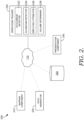
- Example system 200 includes network 110, which is described in connection to FIG. 1 and which communicatively couples components of system 200, including mapping component 210, path generator 220, operations tracker 230, presentation component 240, and data store 250.
- components of system 200 including mapping component 210, path generator 220, operations tracker 230, presentation component 240, and data store 250.
- mapping component 210 e.g., mapping component 210
- path generator 220 e.g., a set of compiled computer instructions or functions, program modules, computer software services, or an arrangement of processes carried out on one or more computer systems, such as computing device 1400 described in connection to FIG. 14 , for example.
- the functions performed by components of system 200 are associated with one or more computerized facility operations applications, services or routines that mange operations at a facility, such as sorting operations at a sorting facility.
- Such applications, services, or routines may operate on one or more user devices (such as user device 102), servers (such as server 106), may be distributed across one or more user devices and servers, or be implemented in the cloud.
- these components of system 200 may be distributed across a network, including one or more servers (such as server 106) and client devices (such as user device 102), in the cloud, and/or may reside on a user device, such as user device 102.
- functionality is described herein with regards to specific components shown in example system 200, it is contemplated that, in some embodiments, functionality of these components can be shared or distributed across other components.
- Mapping component 210 may generally be configured to facilitate the creation and maintenance of a mapping of sensors within a geographical environment, such as a facility.
- embodiments of this invention may include a plurality of sensors configured to track parcels being transported through a facility, such as a sorting facility.
- FIG. 3 a schematic diagram of an environment 300 is provided to illustrate how one or more parcels may interact with various sensor components within a facility.
- Environment 300 may be a sorting facility as described herein.
- Environment 300 may include a plurality of conveyor apparatuses, such as conveyor apparatus 310A and conveyor apparatus 310B, which may be collectively or generally referred to as conveyor apparatus(es) 310 unless otherwise noted).
- Each conveyor apparatus 310 may be responsible for shifting parcels, such as parcels 320A, 320B, and 320C. which may be collectively or generally referred to as parcel(s) 320 unless otherwise noted, from one position to another in environment 300.
- Conveyor apparatuses 310 within environment 300 may be directly or indirectly coupled to one another such that a parcel being moved by one conveyor apparatus (e.g., 310A) may be subsequently moved by another conveyor apparatus (e.g., 310B).
- the term "conveyor apparatus” may include any suitable assembly that includes a conveyor belt (continuous medium that carries parcels from one location to another) and/or one or more rollers or idlers that either rotate the belt or rotate (without a belt) such that parcels are moved.
- a conveyor belt continuous medium that carries parcels from one location to another
- rollers or idlers that either rotate the belt or rotate (without a belt) such that parcels are moved.
- Environment 300 further includes a plurality of sensors, such as readers 330A, 330B, and 330C, which may be collectively or generally referred to as reader(s) 330 unless otherwise noted, that are positioned to "read" data from parcels being moved along a conveyor apparatus 310.
- a reader 330 determines information about a parcel from a tag affixed to a parcel, such as tag 322A affixed to parcel 320A.
- a reader 330 may be integrated into a conveyor apparatus 310, such as reader 330A integrated into conveyor apparatus 310A.
- a reader 330 may be integrated into other structures, such as reader 330B that is configured to read tags on parcels on conveyor 310B but may be affixed to a separate structure within environment 300.
- readers 330A and 330B are depicted as being relatively static in their position in that readers 330A and 330B are each installed on a physical structure, other readers, such as reader 330C may be integrated into a portable and/or wearable device.
- reader 330C is part of a wearable device worn by an employee that may be responsible for physically moving parcels, coordinating the movement of parcels, or monitoring the movement of parcels.
- each reader 330 may include a sensor that is configured to read tags or other identifying information on a parcel 320 that is within a threshold geographical range and/or signal strength.
- reader 330A may be positioned so that it can read tag 322 on parcel 320A as parcel 320A is moved along conveyor apparatus 310A.
- Reader 330A and tag 322A represent example components for this discussion, but it is understood that each of readers 330B and 330C and tags 322B and 322C may operate in a similar manner unless otherwise noted.
- a reader 330 may read tags 322 for multiple parcels 320.
- reader 330A may, at different points in time, read tags 322A and 322C to obtain information on parcels 320A and 320C, respectively.
- a tag 322 on a parcel 320 may be read by multiple readers 330 as the parcel 320 is transported through environment.
- tag 322C on parcel 320C may be read by readers 330A and 330C when a parcel 320 is within a threshold distance of each respective reader.
- Embodiments of readers 330 (such as reader 330A) and tags 322 (such as tag 322A) in environment 300 may be radio-frequency identification (RFID) devices, near-field communication (NFC) devices, or any other suitable combination of reader and/or tag devices equipped that communicate, via either one-way or two-way communication, when in a threshold geographical range and/or signal strength.
- RFID radio-frequency identification
- NFC near-field communication
- tag 322A affixed to parcel 320A may include a radio transponder to receive signals from and transmit signals to a reader 330A
- reader 330A may include a receiver or, in some embodiments, a transponder to receive and transmit signals.
- Readers 330 and tags 322 may communicate via active, passive, or semi-passive communication.
- a tag 322 may include an active RFID tag with at least one input interface for connecting with sensors located in a reader 330.
- Another embodiment of a tag 322 may be a passive RFID tag that is interrogated by an interrogator signal from a reader 330 before transmitting signals to the reader 330 in response.
- a tag 322 and a reader 330 are not limited to RFID, NFC, or similar technologies but may broadly include other embodiments where any data is read from any suitable medium.
- a tag 322 may comprise or include a paper or other medium that includes a barcode, QR code, data matrix code, smart code, or other code or computer-readable indicia of identifiers.
- any suitable associated machine reader can be used to read the code of identifiers, such as an electronic scanner (e.g., a bar code scanner) or device with an optical or infrared sensor.
- reader 330 may represent an electronic scanner, QR code reader, or any variety of suitable readers.
- a tag 322 may provide (actively or passively) identifying information about a parcel 320 to which the tag 322 is coupled, such as a parcel identification number. Additional identifying information may be provided, such as destination, type, and size of a parcel 320. For example, FIG. 3 depicts tag 322A including a parcel ID number, destination, size, and type of parcel for parcel 320A.
- a reader 330 may utilize RFID or NFC technology to receive signals with some identifying information from a tag 332 but may also include an optical sensor for determining other information about a parcel 320.
- a tag 322 includes an intemal clock and includes a time when sending the signal to a reader 330.
- reader 330 may have an internal clock to associate a time of signal receipt with the identifying information received from tag 322. Further, an indication of signal strength received from a tag 322 may be determined and associated with the signal. For instance, signal strength may be stronger when the signal is received by a reader 330 that is closer to a tag 322, such as a signal from tag 322A to reader 330A in FIG. 3 . Additionally, if an optical sensor is utilized, a reader 330 may receive an indication of the position of a tag 322 based on the view of the tag 322 from the optical sensor.
- reader 330 may be communicatively coupled to one or more user devices, such as user device 102 and/or one or more servers 106, either of which may be executing functions of components of computing system 200 described herein.
- a reader 330 may be communicatively coupled to a data store, such as data store 250 of FIG. 2 , to store information that will be utilized by one or more other components of computing system 200.
- the information provided by a reader 3330 including the information from a tag 322, may be utilized to create a mapping of a facility (e.g., environment 300), track parcels, and/or track operations within the facility.
- a reader 330 may also be communicatively coupled to one or more other components responsible for transporting parcels within facility. For example, information from a reader 330 may be utilized to adjust operations for one or more conveyor apparatuses 310 as well as loading/unloading apparatuses and/or storage units within a facility.
- each parcel could take within a sorting facility based on different factors, such as the location at which the parcel is unloaded, the next shipping destination, parcel type, parcel size, which conveyor apparatuses are operating, and/or the existence and location of any blockages on a conveyor apparatus, for example.
- the path of each parcel may be tracked utilizing information from sensors, such as readers 330 in FIG. 3 , and a mapping of the sensors within the facility.
- Mapping component 210 in system 200 may create a mapping, which may also be referred to herein as a configuration file, assigning sensors to workspaces within the facility.
- a "workspace" may refer to a discrete geographical location with the facility that may be utilized in sorting parcels.
- a workspace may be a physical structure or at least part of a physical structure within the facility. Generally, each workspace is within at least part of the range of the sensor such that each workspace indicates a particular geographical area in which the sensor can read tags on parcels.
- a workspace may represent an entire conveyor apparatus or a portion of a conveyor apparatus.
- a workspace may also represent a loading or unloading dock, a shaft or chute, a platform, a storage container, a holding area, or a transition area.
- reader 330A may be mapped to a section of conveyor apparatus 310A; reader 330B may be mapped to a section of conveyor apparatus 310B; and reader 330C may be mapped to a transition area or juncture between the end of conveyor apparatus 310A and another conveyor apparatus or package cart.
- the configuration file representing the mapping may include a list of sensors within a sorting facility or an area to be monitored within the sorting facility.
- the sensors in the configuration file may correspond to wearable devices, such as reader 330C, or readers on fixed physical locations, such as readers 330A and 330B.
- a workspace is assigned and, in exemplary embodiments, additional information identifying properties of the sensor and/or location is assigned.
- the configuration file may indicate a type of sensor, which may be an operation corresponding to a workspace. Examples of types of sensors may include unload, primary in, primary out, metro, DA area, wearable, package car, high value, sure post, SLAW and/or small sort.
- the configuration file may indicate whether the sensor is a start node or an end node.
- a start node represents a location that is the start of a valid parcel path (e.g., where a path is unloaded into the facility), and an end node represents a location that is the end of a valid parcel path (e.g., where a parcel is deposited to be transported away from the sorting facility).
- sensors that do not represent a start node or an end node represent an intermediate location that a parcel may go through between a start node and an end node when traveling through the facility.
- Each workspace location in a configuration file may be represented by both a row and a column with a location adjacency matrix.
- Each cell within a location adjacency matrix may include either a "1'' to indicate that there is a valid connection between the two locations corresponding to the row and column or a "0'' to indicate there is not a valid connection between the two locations.
- Location adjacency matrix 400 may also indicate directional relationships between the locations such that the particular order for sensor reads with valid connections are identified.
- a row indicates a prior location and a column indicates a subsequent location such that a cell at the intersection of a row and column indicates whether there is a valid connection from the workspace of the row to the workspace of the column.
- a valid path for a parcel within location adjacency matrix 400 may be from location 1 to location 2 to location 3. in that order.
- location adjacency matrix 400 indicates a valid connection at cell 402 when going from location 1 and location 2 but an invalid connection at cell 404 when going from location 2 to location 1.
- mapping component 210 may receive input from a user indicating information for the configuration file, including the location adjacency matrix. The initial mapping and adjacency information may be validated using data of parcels moving through the facility. As such, in some embodiments, mapping component 210 receives reference parcel tracking data that includes a plurality of scan for parcels moving through the facility. The reference parcel tracking data may be received from storage, such as data store 250, or directly from sensors, such as readers 108 in FIG. 1 . The reference parcel tracking data may be compared to the configuration file to identify potential errors in the configuration file.
- the reference parcel tracking data may be utilized to check for missing expected location properties, for missing values recorded for location properties, whether every location is either a start node or validly follows at least one other location, whether every location is either an end node or validly precedes at least one other location, and whether every location in the reference parcel tracking data exists in the configuration file.
- mapping component 210 may determine whether any location in the reference parcel tracking data appears for the start of a path for a parcel but is not identified as a valid start node in the configuration file, whether any location in the reference parcel tracking data appears for the end of a path for a parcel but is not identified as a valid end node in the configuration file, and whether every transition in the reference parcel tracking data is valid according to the configuration file.
- Any error which may represent a mismatch between the reference parcel tracking data and what is expected from the configuration file, may be flagged.
- the error is flagged for manual review by a user, and the user may determine whether to update the configuration file to be consistent with the reference parcel tracking data.
- the updated configuration file may be saved to storage, such as data store 250.
- location adjacency information may be automatically determined from reference parcel tracking data. For example, valid connections may be determined by applying one or more machine learning algorithms to the reference parcel tracking data. In some embodiments, identifying locations as start nodes and stop nodes may also be performed automatically.
- updating information in the configuration file may be based on a relocation or reconfiguration of a sensor. For example, based on a comparison of the configuration file and the reference parcel tracking data, a missing read from a sensor may be detected where the reference parcel tracking data does not include a read that is expected from the valid connections in the configuration file. Additionally, a bleeding read from a sensor may be detected where the reference parcel tracking data includes reads of the same parcel from two sensors within a pre-determined time window, indicating that one sensor is reading parcels in a workspace location assigned to another sensor. In response to the detected missing reads and bleeding reads, one or more sensor locations and configurations may be adjusted to reduce the likelihood of future errors, and the configuration file may be updated to reflect the changes to the sensor.
- the configuration file may be utilized to identify paths of parcels being transported through the facility based on new parcel tracking data from sensors.
- Path generator 220 in FIG. 2 may generally be configured to generate paths of a parcel as it moves through the facility based on parcel tracking data from a plurality of sensors. As a parcel is moved through the facility, multiple sensors (e.g., readers 330) may read a tag (e.g., 322) attached to the parcel and the information from those reads (referred to as parcel tracking data) may be utilized to determine locations of the parcel within the facility, including determining likely transitions from one location to another.
- path generator 220 may aggregate the parcel's parcel tracking data provided by multiple sensors and determine a sequence of workspace locations matching each read event (e.g., a scan of a tag by a sensor) in the parcel tracking data utilizing the configuration file.
- each read event e.g., a scan of a tag by a sensor
- the parcel tracking data is cleaned before being used to generate parcel paths.
- Cleaning may include, for each read event in the parcel tracking data, normalizing read properties to enable comparison of strings, data, and timestamps, replace invalid signal strengths with full strength values, normalize location values to distinguish wearable sensors from static sensors as indicated by the sensor type in the configuration file, remove all read events that are exact duplicates, and remove read events without certain information, such as a parcel ID, time stamp, or sensor identifier.
- cleaning may include additional functions, such as removing read events for parcels with parcel IDs that do not match a valid format, remove scans for parcels with a total number of read events exceeding a threshold amount, and remove read events for packages that are flagged as having left the facility.
- the functions that are performed during cleaning may be user-specified functions.
- path generator 220 may determine a chronological sequence of read events based on the time stamps of each read event and determine a chronological sequence of the workspace locations corresponding to the sensors associated with the read events. For example, if parcel tracking data has read events associated with the same parcel ID with time stamps of 10:42:10 a.m., 10:45:50 a.m., and 10:49:50 a.m. from sensors assigned to workspace locations A. B, and C, respectively, path generator may determine that the path for the particular parcel goes from A to B to C.
- generating a path for a parcel may include determining a most likely location from multiple locations that are associated with read events for the same parcel.
- parcel tracking data is received from sensors for a plurality of parcels.
- generating a path may include first sorting the read events occurring to a common parcel ID and then by time stamp. For each unique parcel ID, the time stamps for corresponding read events are utilized to determine potential locations within a predetermined window of time. For each read event, the amount of time since the previous read event with the same parcel ID is calculated and compared to a predetermined window of time, such as five seconds.
- the read event may be considered "in window".
- satisfying the predetermined window of time comprises not exceeding the predetermined window of time.
- a read event may defined as "in window” even if it is out of the predetermined window (i.e., exceeds the predetermined window) when the previous location and the location of the new sensor event are the same, indicating that the parcel has not moved.
- a read event that does not satisfy the predetermined window of time may be considered to be "not in window”. If a read event is "in window”, it may be consolidated with other read events for that window of time, and a read event that is "not in window” may be added to the subsequent window of time.
- path generator 220 may determine the most likely location for the parcel for that window of time. Where the read events are from the same sensor, the location of the parcel is determined to be the workspace location assigned to that sensor. However, there may be instances in which multiple sensors are providing read event data for the same parcel ID within the same window of time. In exemplary embodiments, path generator 220 applies one or more heuristic rules to determine which read event (and, thus, which sensor) should be utilized in determining the workspace location for the window of time. In some embodiments, path generator 220 may determine the most likely location by determining the read event that occurs first within the window of time and determining the workspace location assigned the sensor providing that read event.
- path generator 220 may determine the most likely location by determining the read event that has the highest signal strength value out of all the read events within the window of time for a particular parcel and determining the workspace location assigned to the sensor that provided that read event with the highest signal strength value. Still, in other embodiments, path generator 220 may select the most likely location to be the most commonly occurring location, where the most commonly occurring location may be a location that appears most frequently in reference tracking data, a location that appears most frequently in for tracking data for all parcels within that facility for a given time frame, or a location that appears most often for the particular parcel being tracked within that window of time. In another embodiment, path generator 220 may select the most likely location of a parcel for a given window of time to be the most recent location.
- path generator 220 may combine the determined locations to create a raw path for the parcel.
- the raw path may represent an initial determination of the chronological sequence of workspace locations in which a parcel moved through within the facility.
- Path generator 220 may amend the raw path by inserting new locations and/or deleting existing locations in the raw path. The amendments may be made in response to detecting errors (e.g., invalid start/end nodes or illegal transitions) in the raw path utilizing the configuration file. For example, for the first location within the raw path, which represents the first location chronologically, path generator 220 may determine whether the location is identified as a valid start node in the configuration file. If the first location is not a valid start node, path generator 220 may determine that either the first location is incorrect or another location should be added to the beginning of the raw path. A similar determination may be made with respect to the whether the last location within the raw path is identified as a valid end node in the configuration file.
- errors e.g., invalid start/end nodes or illegal transitions
- path generator 220 may identify an illegal transition by determining that a pair of successive locations in the raw path do not form a valid transition identified in the configuration file. For example, if the raw path includes a sequence of locations A, E, F, G, and I, and the configuration file identifies locations B and C as the only next valid locations after location A, then location E may be determined to represent an invalid location, indicating that either location E should be changed or one or more additional locations should be inserted between locations A and E.
- path generator 220 may determine possible alternative paths by adding and/or deleting locations so that the path for a parcel ID includes a valid start node, valid transitions, and, in some aspects, valid end nodes. This process may result in multiple valid alternative paths being identified, and path generator 220 may apply one or more algorithms to automatically determine the most likely path. For instance, in exemplary aspects, path generator 220 may utilize an edit distance algorithm to automatically determine the most likely path. When applying edit distance, the total number of amendments required to change the raw path to an alternative path is determined.
- amendments to a possible path are weighted in by the likelihood of occurrence, which may be determined based on historical parcel tracking data, where amendments resulting in transitions that occur more frequently in the historical data may be weighted in favor of a more likely path (e.g., weighted less for a lower edit distance).
- the possible amended path with the lowest edit distance is selected as the path for the parcel.
- path generator 220 determines the likely path that a parcel took through a facility. Further, in exemplary embodiments, path generator 220 determines the path that a parcel takes in real time or near real time such that paths for parcels may be determined while the parcels are still being transported through the facility. In embodiments in which paths are determined in real time or near real time, the determined path may be only a partial path reflecting the path that the parcel has taken thus far as indicated by the parcel tracking data that has been received. In some embodiments, path generator 220 receives parcel tracking data continuously. In some embodiments, path generator 220 receives the parcel tracking data in regular intervals, such as every minute. Paths determined for a parcel may be updated as additional tracking data is received with read events for that parcel.
- Newly received parcel tracking data for a parcel may not only indicate new locations but may be utilized to revise locations previously determined within the path. Because path generator 220 may determine partial paths, in some embodiments, path generator 220 does not determine valid end nodes as the parcel may not have reached a valid end node within the facility yet. In some embodiments, path generator 220 only determines if there is a valid end node in the parcel tracking data for a parcel where time elapsed since either the last read event or the first read event for the parcel exceeds a predetermined threshold amount of time, indicating that the parcel likely has left the facility.
- Embodiments of system 200 may further comprise operations tracker 230 that is generally configured to utilize paths generated for one or more parcels to track operations within a sorting facility. As shown in FIG. 2 , embodiments of operations tracker 230 may further include path error detector 232, slowdown detector 234, employee attributor 236, and volume determiner 238. Operations tracker 230 or any of the subcomponents may be implemented on the same computing device, as mapping component 210 and/or path generator 220 or may be implemented on a separate computing device, such as a separate server, such that these functionalities may be performed in a distributed architecture.
- Path error detector 232 may generally be configured to detect an error in the path a parcel is taking or has taken through the facility.
- a path error occurs when a parcel's path, as determined by path generator 220, does not match the path expected to be taken by the parcel based on how the parcel was to be sorted.
- a path error may be due to a misload of the parcel when transportation has started or a missort of the parcel during transportation and, as such, may be referred to herein as a missort or a misload.
- the path error occurs because of a misprint of loading instructions for the parcel or an employee placing the parcel on the wrong bed or conveyor apparatus.
- a graphical user interface component is generated in response to a path error being detected by path error detector 232 as described below with respect to presentation component 240 as well as FIGS. 5 , 6A-6F , and 10 .
- path error detector 232 may also determine a next workspace location to which the parcel should be transported in order to put the parcel on the expected path. This next location may be the location within the expected path that is nearest the current location of the parcel. Further, in some aspects, only some of the locations along a path may allow for automatic or human intervention to correct a parcel's path.
- Slowdown detector 234 is generally responsible for determining when the rate of parcel transportation has slowed down within a the facility or a particular area of the facility. A slowdown, for instance, may occur due to high parcel volume, obstructed path, and/or faulty or broken equipment. As a result, at least some parcels may not be transported through the facility as quickly as expected. Slowdown detector 234 may utilize time information from read events to determine the length of time it took a parcel to move between workspace locations within a parcel's determined path. For instance, path generator 220 may determine that a parcel has traveled between location A and location B based on a read event taken at 10:42 am by a reader mapped to location A and a read event taken at 10:50 am by a reader mapped to location B. Based on this information, it may be determined that it took the parcel eight minutes to move from location A to location B.
- Slowdown detector 234 may determine the presence of a slowdown by comparing the length of time it takes a parcel to move between two locations to a predetermined threshold length of time.
- the predetermined threshold length of time may be specific to the two locations being considered for the parcel (e.g., there may be a threshold time specific to traversing between locations A and B and another threshold time specific to traversing between locations B and C).
- the threshold length of time between two particular locations may be based on historical parcel tracking data.
- the threshold length of time to traverse two locations may be a set deviation from the average length of time (e.g., one standard deviation, two standard deviations, etc.) it took parcels to move between those two locations in the historical parcel tracking data.
- slowdown detector 234 may determine that a slowdown has occurred when the length of time it takes for a parcel to be transported between two locations satisfies the predetermined threshold length of time.
- the predetermined threshold length of time may be satisfied when the determined length of time of the parcel being tracked is greater than or equal to the threshold length of time or, in other aspects, when the determined length of time is greater than the threshold length of time.
- slowdown detector 234 may detect slowdowns by comparing the length of time it takes the parcel to complete each subpath with the respective threshold length of time. In response to detecting a slowdown, a signal may be sent to one or more user devices to provide an alert of the slowdown so that it may be remedied.
- the alert may be provided in the form of a graphical user interface component generated in response to the slowdown being detected by slowdown detector 234 as described below with respect to presentation component 240 and FIG. 6C .
- an employee's parcel count is 200 during a relevant time period and the error count is 20, it may be determined that the number of parcels the employee sorted without errors is 180 and the accuracy measurement may be 90%. In this example, an error rate may be 10% for that employee.
- employee attributor 236 may further predict a likelihood of a particular employee causing a path error, such as a misload or missort.
- the error may be predicted utilizing one or more machine learning models.
- a logistic regression model is employed to predict a probability of an error.
- Employee attributor 236 may utilize the machine learning model to predict an error based on the employee's historical accuracy information, such as error count and accuracy measurement.
- the error prediction output by employee attributor 236 may be a quantitative probability (e.g., 60% likelihood of an error for a particular employee) or a categorical probability (e.g., high, medium, or low likelihoods of an error for a particular employee).
- Additional contextual information may be utilized, such as the workspace location, day of the week, the time, the time elapsed since the beginning of the shift, to predict an error for an employee. For instance, an employee may be more likely to make an error at the end of a shift or when it is late at night.
- the machine learning model may be trained utilizing data of a reference population or data for a specific employee. As such, the machine learning model may predict a probability of an error for an employee not only based on a generalized higher likelihood of errors occurring at the end of a shift but based on historical data for that particular employee showing more errors occurring at the end of the employee's shifts.
- the specific features utilized to train and run the machine learning model may be selected utilizing Least Absolute Shrinkage and Selection Operator (LASSO) technique.
- LASSO Least Absolute Shrinkage and Selection Operator
- the employee attributor 236 may utilize a logistic regression LASSO model.
- Volume determiner 238 may determine parcel volume for a workspace location, a path or subpath, and/or an entire facility. To determine parcel volume for a workspace location, volume determiner 238 may determine the count of unique parcel IDs associated with paths (which may be generated by path generator 220) that contain the workspace location for a given period of time. Similarly, to determine parcel volume for a path or subpath, volume determiner 238 may determine the count of unique parcel IDs associated with the path or subpath, where a path or a subpath is defined by a sequence of locations. For instance, to determine a volume for subpath between location A and location B. the count of unique parcel IDs associated with a path containing the sequence of location A followed by location B would be determined by volume determiner 238.
- System 200 may further include presentation component 240 that is generally responsible for presenting one or more outputs of components of system 200, such as a parcel path determined by path generator 220 or a facility operation determined by operations tracker 230, to a user.
- path generator 220 and/or operations tracker 230 may operate in conjunction with or may be implemented as one part of presentation component 240.
- Presentation component 240 may comprise one or more applications or services on a user device, across multiple user devices, or in the cloud. For example, in one embodiment, presentation component 240 manages the presentation of communications, such as notifications and alerts, to a user across multiple user devices associated with that user.
- presentation component 240 may determine on which user device(s) to present the content, as well as the context of the presentation, such as how to present (including in what format and how much content, which can be dependent on the user device or context), when to present, or other such aspects of presentation.
- presentation component 240 generates user interface (UI) features associated with or used to facilitate presenting to the user aspects of path generator 220 and operations tracker 230.
- UI user interface
- Such features can include UI elements (such as icons or indicators, graphics buttons, sliders, menus, audio prompts, alerts, alarms, vibrations, pop-up windows, notification-bar or status-bar items, in-app notifications, or other similar features for interfacing with a user), queries, and prompts.
- UI elements such as icons or indicators, graphics buttons, sliders, menus, audio prompts, alerts, alarms, vibrations, pop-up windows, notification-bar or status-bar items, in-app notifications, or other similar features for interfacing with a user
- queries, and prompts may be combined to create a user interface, such as a graphical user interface, for tracking paths of parcels within a facility, operation errors, such as loading errors or an error resulting in a slowdown, volume of parcels within the facility, and/or employee productivity.
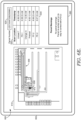
- FIG. 5 depicts an example graphical user interface (GUI) 500 for tracking the path of a parcel within a sorting facility.
- GUI 500 may be generated by an embodiment of presentation component 240.
- GUI 500 may be displayed on a user device 502, which may be an embodiment of user device 102 in FIG. 1 .
- GUI 500 may be provided on user device 502 as part of a parcel tracking application running on user device 502 or on a remote server accessed by user device 502.
- GUI 500 may include UI elements that indicate previous or current locations of a parcel.
- a parcel identifier 520 includes text identifying the specific parcel for which a location is being tracked.
- one of the features of GUI 500 may provide a schematic mapping of a parcel's track throughout the facility.
- GUI 500 includes parcel map 510 that schematically represents a layout of a sorting facility and identifies positions of the parcel identified by parcel identifier 520 within a facility.
- parcel map 510 may depict one or more workspace locations at which a parcel may be found.
- parcel map 510 depicts a plurality of loading stations 540, a plurality of conveyor apparatuses 550, and a plurality of unloading stations 560. Additional workspace locations may be depicted depending on the layout of the specific sorting facility.
- Each workspace location within parcel map 510 may be mapped to one or more readers within a configuration file created by an embodiment of mapping component 210 of FIG. 2 .
- Parcel map 510 may further include one or more parcel location indicators that indicate a specific location (i.e., workspace location) of the parcel within the sorting facility. Additionally, determinations of the locations of the parcel represented in parcel map 510 may be done by an embodiment of path generator 220 of FIG. 2 . In this way, parcel location indicators may be based on reads of the parcel as the parcel travels through the sorting facility that is represented in parcel map 510. Parcel map 510 has a location indicator 572 at unloading station 562. a location indicator 574 at a portion of conveyor 552 corresponding to PD-2A.
- Parcel map 510 may further include one or more direction indicators, such as arrow 554, that indicate a direction in which the parcel is traveling along the path.
- Graphical user interface 500 may include a location table 530 that includes descriptors for the locations at which a parcel was tracked in the facility and times corresponding to those locations. These times may be the times of read events from readers mapped to the identified workspace locations. As illustrated, each location in location table 530 corresponds to one of the location indicator(e.g., location indicator 572) in parcel map 510.
- one or more elements of GUI 500 are user interface elements that a user may interact with to modify GUI 500.
- parcel identifier 520 may have functionality of a drop down menu and/or search bar that allows a user to search for or select another parcel.
- parcel map 510 and location table 530 may be updated to reflect locations of the other parcel.
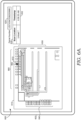
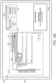
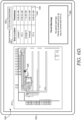
- FIGS. 6A-6F depict a series of screenshots of an example graphical user interface (GUI) 600 that may be presented to a user to track a parcel as the parcel is moved throughout the facility.
- GUI 600 may be generated by an embodiment of presentation component 240 and utilizing one or more of the other components of system 200, such as path generator 220 and operations tracker 230. Further, GUI 600 may be displayed on a user device 602, which may be an embodiment of user device 102 in FIG. 1 .
- GUI 600 may be provided on user device 602 as part of a parcel tracking application running on user device 602 or on a remote server accessed by user device 602.
- GUI 600 depicted in FIGS. 6A-6F may include UI elements that indicate one or more locations of a parcel.
- GUI 600 may include a parcel identifier 620 with a descriptor identifying the specific parcel for which a location is being tracked.
- GUI 600 may further include parcel map 610 that schematically represents a layout of a facility and identifies positions of the parcel identified by parcel identifier 620 within the facility.
- parcel map 610 may depict one or more workspace locations at which a parcel may be found. For instance, parcel map 610 depicts a plurality of loading stations 640, a plurality of conveyor apparatuses 650, and a plurality of unloading stations 660. Additional workspace locations may be depicted depending on the layout of the specific sorting facility. Each workspace location within parcel map 610 may be mapped to one or more readers within a configuration file created by an embodiment of mapping component 210 of FIG. 2 .
- GUI 600 may also include location table 630 that includes descriptors for the locations at which a parcel was tracked in the facility and times corresponding to those locations. These times may be the times of read events from readers mapped to the identified workspace locations. As illustrated, each location in location table 630 may correspond to a location indicator, such as location indicator 672 discussed below, in parcel map 610.
- GUI 600 may be updated in real time or as the parcel is being moved through the facility.
- screenshots in FIGS. 6A-6F are provided to illustrate examples of updates to GUI 600 as a parcel is moved through facility; however, it is contemplated that there may be other updates to GUI that are not specifically depicted in a separate screenshot here but that may be presented to on a user device.
- parcel map 610 includes a location identifier 672 indicating a parcel's was last located at unload station 662.
- Location table 630 may also include row 632 with text identifying the workspace location corresponding to location identifier 672 and the time stamp of the read event corresponding to location identifier 672.
- location identifier 672 is moved from unload station 662 to workspace location 652, which may be referred to as PD-1, and a new row 634 is added to location table 630 to add the new location and time stamp corresponding to workspace location 652.
- graphical user interface 600 further includes a warning status 680 identifying an error with the parcel location.
- Warning status 680 may be generated or, in some instances, updated in response to a determination of this error by an embodiment of path error detector 232 of FIG. 2 .
- warning status 680 indicates that there is a parcel missort, that the parcel was seen at PD-1, and that the correct workspace location is PD-2.
- location identifier 672 is moved from workspace location 652 to workspace location 654, which may be referred to as Orange In, and a new row 636 is added to location table 630 to add the new workspace location and time stamp corresponding to workspace location 654.
- GUI 600 still includes warning status 680 that is updated to indicate the previous parcel missort is continued but now identifies the more recent workspace location. Warning status 680 is also updated to add a parcel slowdown warning. The parcel slowdown may be determined based on the times between successive reads for a parcel as described in conjunction with slowdown detector 234 in FIG. 2 .
- location identifier 672 is now positioned at workspace location 656, which may be referred to as PF-2, and new rows 638 and 642 have been added to location table 630 to include two new locations and corresponding timestamps.
- GUI 600 may have been updated with row 638 and a corresponding position of location indicator 672 on parcel map 610 prior to the update shown in FIG. 6D .
- GUI 600 still includes warning status 680, which is updated to indicate that previous missort has been fixed as the parcel is in the correct location now and that there are no warnings.
- location identifier 672 is moved from workspace location 656 to workspace location 658, which may be referred to as PE-2. and a new row 644 is added to location table 630 to add the new location and time stamp corresponding to workspace location 658.
- warning status 680 still indicates that the previous missort has been fixed.
- location identifier 672 is positioned at workspace location 641, which may be referred to as Outbound 3, and new rows 646 and 648 have been added to location table 630 to include two new locations and corresponding timestamps.
- the parcel moved PE-2, to PE-3, to Outbound 3 and parcel map 610 indicates that the last detected location of parcel is workspace location 641 corresponding to Outbound 3.
- GUI 600 may have been updated with row 646 and a corresponding position of location indicator 672 on parcel map 610 prior to the update shown in FIG. 6F .
- warning status 680 states that the parcel was left in the building. This determination may be made based on the time between successive read events for the parcel by a reader at workspace Outbound 3 exceeding a threshold time.
- visual representations of a parcel's location may be provided to a user in real time as the parcel is moved through a facility. Additionally, errors and resolutions to errors may be presented to the user in real time.
- the location indicator 672 moves to new positions within parcel map 610 as new locations of the parcel are determined from more recent parcel tracking data. It is contemplated that parcel map 610 may include indicators of previously determined locations as new locations are determined similar to GUI 500 of FIG. 5 .
- FIGS. 7 and 8 depict example embodiments of graphical user interfaces with elements indicating volumes of parcels.
- the graphical user interfaces (GUIs) 700 and 800 of FIGS. 7 and 8 may each be generated by an embodiment of presentation component 240. Additionally, parcel volumes utilized to generate GUIs 700 and 800 may be determined utilizing embodiments of volume determiner 238 of system 200. Further, GUIs 700 and 800 may each be displayed on a user device, such as user device 702 and 802, respectively, each of which may be an embodiment of user device 102 in FIG. 1 . GUIs 700 and 800 may be provided on user device 702 and 802 respectively as part of a parcel tracking application running on the respective user devices or on a remote server accessed by such devices.
- GUI 700 is depicted comprising a graph 710 that represents volumes of parcels across various paths and subpaths for a period of time.
- the y-axis of graph 710 identifies workspace locations within a facility that a parcel may be coming from, and the x-axis of graph 710 identifies workspace locations within a facility that a parcel may be going to.
- graph 710 indicates a volume of parcels that took that path between the two locations.
- the indication may be text written in a cell within the grid created by graph 710 as shown in FIG. 7 . Additionally or alternatively, the indication may be a color such that different colors or shades indicate different volumes.
- the parcel counts for each path are assigned a color or shade according to a gradient, which may be represented as a gradient legend tool 720 in GUI 700.
- a gradient legend tool 720 in GUI 700.
- both text and varying shades are used to indicate the volume of parcels.
- cell 730 within graph 710 represents a path from "DAIN" location to "SMALLSSORT2" location, and cell 730 includes the number "3" and is a dark shade of gray.
- Cell 740 represents the path from "Unload 9" location to "Preload” location, includes the number “711” and is a lighter shade of gray, indicating that the path from "Unload 9" to "Preload” has a higher volume of parcels within the relevant time period compared to the path from "DAIN" to "SMALLSORT2". Shades of gray are utilized for purposes of FIG. 7 , but it will be appreciated that GUI 700 may utilized different colors to indicate different levels of parcel volume.
- Parcel volumes utilized in generating GUI 700 may be determined from parcel tracking data by an embodiment of volume determiner 238 described in conjunction with FIG. 2 .
- the volume of parcels depicted through UI elements of GUI 700 may be determined for a particular period of time.
- the relevant time period is one day
- GUI 700 includes a drop down menu 750 for selecting a date.
- a user may select other dates to be presented with similar graphs representing volumes for the other dates.
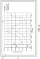
- FIG. 8 illustrates a GUI 800 that depicts parcel volume over time.
- GUI 800 includes a line graph 805 with date represented by the x-axis and parcel count represented by the y-axis.
- the parcel counts may be separated according to type of sensor.
- line 810 represents the parcel count from antennas:
- line 820 represents the parcel count from sensors on small sort devices;
- line 830 represents the parcel count from wearable sensors.
- the relevant volume represented by GUI 800 may be for an entire sorting facility or an area within the facility. As such, GUI 800 may be generated to provide a visual representation of productivity within a facility or area within a facility over time.
- Parcel volumes utilized in generating GUI 800 may be determined for each date from parcel tracking data by an embodiment of volume determiner 238 described in conjunction with FIG. 2 . While GUI 800 illustrates how parcel volume may vary across different days of the week, the visual representation of parcel volume over time in GUI 800 may help identify unusual or unexpected changes in parcel volume.
- FIGS. 9A and 9B each depict an example GUIs that indicate employee performance within a sorting facility.
- the GUIs 900 and 950 of FIGS. 9A and 9B may each be generated by an embodiment of presentation component 240. Additionally, employee parcel and error counts utilized to generate the GUIs 900 and 950 may be determined in accordance with embodiments of one or more subcomponents of operations tracker 230, such as path error detector 232 and employee attributor 236. Further, GUIs 900 and 950 may each be displayed on a user device 902, which may be an embodiment of user device 102 in FIG. 1 . GUIs 900 and 950 may be provided on user device 902 as part of a parcel tracking application running on user device 902 or on a remote server accessed by user device 902.
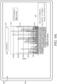
- FIG. 9A illustrates an example GUI 900 that includes graph 910 indicating productivity and accuracy across multiple employees.
- graph 910 includes an x-axis representing employees (using employee identifiers such as employee ID numbers for example), and a y-axis representing parcel counts.
- graph 910 includes a productivity indicator and an accuracy indicator for a particular time period.
- the relevant time period is a one day
- GUI 900 may include a specific period selector, such as drop down menu 916, for a user to select the specific date for the one-day period. As such, a user may view productivity and accuracy for other dates.
- the indicators in graph 910 are in the form of bars such that each employee ID has a productivity bar 912 and an accuracy bar 914.
- Productivity bars 912 each represent a count of parcels that the given employee sorted during the selected time period.
- each read event may provide information identifying the reader participating in the read event and the date and time of the read event, and an employee assigned to the identified reader at the time of the date and time of the read event may be determined. In this way, each read event may be attributed to a particular employee.
- the parcel count indicated by the productivity bar 912 may be determined by aggregating all read events attributed to an employee within the relevant time period and, in some embodiments, removing a read event that is a duplicate parcel ID such that the parcel count only includes read events for unique parcels.
- Accuracy bars 914 each represent a count of parcels that the given employee missorted during the selected time period. As explained above with respect to employee attributor 236, for each read event from which an error is detected, the error may be attributed to the employee assigned to the relevant reader during the time and date of the detected error.
- the parcel count indicated by the accuracy bar 914 may be determined by aggregating all errors resulting from read events attributed to an employee within the relevant time period. In some embodiments, aggregating the errors includes removing a read event that is a duplicate parcel ID such that the parcel count for an accuracy bar 914 only includes unique errors.
- FIG. 9A shows productivity bars 912 and accuracy bars 914 for the same employees overlaying one another on graph 910.
- an accuracy bar 914 may overlay an productivity bar 912 to provide a visual indication of an approximate percentage of parcels resulting in errors out of the total parcels for each employee.
- productivity bars 912 and accuracy bars 914 for the same employees are presented in a stacked arrangement or in a side-by-side arrangement.
- example GUI 900 may also include a hover box 918 with information about a particular employee when a cursor is placed over a portion of graph 910 representing that employee, such as the employee ID number, a productivity bar 912, or an accuracy bar 914.
- hover box 918 may include an employee identifier, such as an employee ID number, one or more accuracy indicators, and relevant notes or messages.
- hover box 918 in graphical user interface 900 includes an employee ID number, a numerical average accuracy, and a message.
- the average accuracy may be computed from accuracy measurements determined for each day over a period of time, such as the period of the employee's employment, the period of the employee's assignment in the current sorting position, or a period of time unrelated to the specific employee, such as three months.
- the message in example hover box 918 displays a probability of misload by the employee. In some embodiments, this type of message of probability of misload is provided only when the probability satisfies a threshold probability, such as 30%. In other embodiments, this type of message is provided for all employees regardless of accuracy.
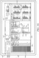
- FIG. 9B illustrates an example GUI 950 that includes graph 960 that indicates productivity and accuracy for an employee across a period of time.
- graph 960 includes an x-axis representing time and a y-axis representing parcel count.
- Graph 960 includes a productivity indicator over time and an accuracy indicator over time.
- the embodiment of graph 960 depicted in FIG. 9B includes productivity line 962 and accuracy line 964.
- Productivity line 962 indicates a total parcel count at various time points represented by graph 910 for a particular employee
- accuracy line 964 indicates a parcel count with errors, such as misloads, attributed to the employee at various time points represented by graph 910.
- the total parcel count and the parcel count with errors for an employee may be determined as described with respect to FIG. 9A .
- Productivity line 962 and accuracy line 964 may be displayed simultaneously to provide an indication of an approximate accuracy percentage by providing a visual comparison of productivity and accuracy.
- GUI 950 is updated in real time or near real time as more parcel tracking data is acquired from readers. As such, GUI 950 may provide a current snap shot of productivity and accuracy while the employee is still working.
- GUI 950 depicted in FIG. 9B is provided in response to selection of an employee within GUI 900 depicted in FIG. 9A .
- GUI 950 may be presented to display a more granular breakdown of the selected employee's productivity and accuracy within the day.
- GUIs 900 and 950 may be provided sequentially or, alternatively, may be provided in combination with each other such that both graphs 910 and 960 are displayed concurrently.
- FIG. 10 depicts an example graphical user interface in the form of a dashboard 1000 indicating various aspects of tracking parcels and operations through a sorting facility.
- Dashboard 1000 may be generated by an embodiment of presentation component 240 of FIG. 2 . Additionally, dashboard 1000 may be created using output of one or more other components of system 200, such as path generator 220 and operations tracker 230. Further, dashboard 1000 may be displayed on a user device 1002, which may be an embodiment of user device 102 in FIG. 1 . Dashboard 1000 may be provided on user device 1002 as part of a parcel tracking application running on user device 1002 or on a remote server accessed by user device 1002.
- Dashboard 1000 may provide visual representations of the flow of parcels through a facility and specific workspace locations in the facility in real time or near real-time.
- Dashboard 1000 includes one or more descriptors relating to the facility and the time.
- dashboard 1000 includes a date descriptor 1004 and a time descriptor 1006 to identify the current date and time, respectively.
- Dashboard 1000 further includes a current flow descriptor 1008 with text identifying the current flow of parcels through the facility, which is 63,980 parcels (or pieces) per hour (PPH).
- PPH 63,980 parcels (or pieces) per hour
- flow is provided as PPH, but it is contemplated that other metrics, such as a parcels per minute or parcel count, may similarly be utilized in dashboard 1000.
- Dashboard 1000 further includes a plurality of UI elements representing expected or actual volumes or flow of parcels through one or more specific portions of the facility.
- dashboard 1000 includes an expected parcel display area 1020 that generally indicates parcels expected to be received by the facility, workspace flow display area 1030 that generally shows the flow or volume of parcels in particular areas within the facility, and a destination tracker display area 1040 generally shows volumes of parcels being loaded for the next destination out of the facility.
- each box within expected parcel display area 1020 may represent a plurality of parcels to allow more parcels to be represented simultaneously in expected parcel display area 1020 and presented to a user. For instance, each box within expected parcel display area 1020 may represent up to 50 parcels.
- workspace flow display area 1030 indicates flows of parcels through each workspace location.
- the workspace locations may be grouped together by workspace type.
- Primary Out flow display area 1031 indicates a flow of parcels for a larger workspace location referred to as Primary Out, as well as a breakdown of specific parcel flows for workspace locations 1033 that form Primary Out.
- Primary Out flow display area 1031 includes a textual descriptor 1037 for the flow of parcels through Primary Out and a bar indicator 1034 that visually represents the of flow of parcels through Primary Out relative to other workspace locations.
- each smaller workspace location e.g., 1033
- each smaller workspace location which may each correspond to a reader, includes a textual descriptor (e.g., 1036) and a bar indicator (e.g., 1035).
- Parcels counted for the flows through workspaces in workspace flow display area 1030 may previously have been accounted for in expected parcel display area 1020.
- expected volumes may be determined from parcel manifests and/or from destination information identified at initial scans of parcels being loaded in the facility.
- the actual parcels that have been loaded may be determined by read events from sensors associated with the workspace locations (e.g., trailers/cars) for the particular destination.
- dashboard 1000 provides flow and volume information in real time or near real time.
- the information provided in dashboard 1000 may be regularly, periodically, or continuously updated.
- dashboard 1000 may be updated every minute with new data received from readers, such as reader 108 described in connection with FIG. 1 .
- dashboard user interface 1000 enables a user to receive up to date information about the facility, quickly identify errors, and manage current or future operations as deemed appropriate based on the current or trends in parcel flow.
- FIGS. 11-13 each depict flow diagrams of example methods performed in accordance with embodiments of this disclosure.
- Each block or step of the disclosed methods comprises a computing process that may be performed using any combination of hardware, firmware, and/or software.
- various functions may be carried out by a processor executing instructions stored in a memory.
- the methods may also be embodied as computer-usable instructions stored on computer storage media.
- the methods may be provided by a stand-alone application, a service or a hosted service (stand-alone or in combination with another hosted service), or a plug-in to another product, to name a few.
- the methods of FIGS. 11-13 described below may be performed by one or more computing devices, such as a smartphone or other user device, a server, or a distributed computing platform, such as in the cloud environment. These methods may be performed by one or more components of system 200 of FIG. 2 .
- FIG. 11 depicts a flow diagram illustrating an example method 1100 for generating a graphical user interface for tracking operations within a facility utilizing read events captured as parcels are transported through the facility.
- a configuration file for the facility is accessed.
- the configuration file may assign readers within the facility to particular workspace locations with the facility. For example, each reader within the facility, which may include static readers and/or wearable readers, may be mapped to a workspace location forming part or an entire physical structure or area within the facility.
- the configuration file may be accessed at step 1102 by embodiments of path generator 220 and/or operations tracker 230 of FIG. 2 . Additionally, the configuration file may be created and maintained by an embodiment of mapping component 210 of FIG. 2 .
- the parcel tracking data includes read events for parcels being transported through the facility. Each read event indicates a reader that captured the read event and a time the read event occurred. Read events may also identify the parcel such as by a parcel identification number, for example. Parcel tracking data may be received by embodiments of path generator 220 and/or operations tracker 230 of FIG. 2 and may be received directly from readers or from a data store, such as storage 250 of FIG. 2 . In exemplary aspects, parcel tracking data is received in real time either continuously or periodically, such as every minute.
- one or more locations for each parcel being tracked is determined utilizing the configuration file and the parcel tracking data.
- Each determined location is a workspace location at which that the parcel has been located during transportation of the parcel through the facility.
- Locations for each parcel may be determined by an embodiment of path generator 220 as described in greater detail with respect to FIG. 2 .
- a path comprising a sequence of locations at which a parcel was detected may be determined.
- the path includes at least three locations, including a start node for parcel transportation, an end node for parcel transportation, and at least one workspace location between the start node and the end node.
- the path is determined as the most likely path by identifying valid connections between subpaths (paths between two detected locations) within read events for a particular parcel.
- the configuration file may indicate valid connections between different combinations of readers.
- an edit distance algorithm is applied to detect the most likely path from the read events, and the algorithm may be weighted in favor of subpaths that are more frequently occurring within historical parcel tracking data for that facility.
- a graphical user interface is generated and caused to be presented on a user device.
- Step 1108 may be performed by an embodiment of operations tracker 230 and, in some embodiments, in conjunction with presentation component 240.
- the graphical user interface is generated based on the one or more locations determined for at least one parcel.
- GUIs 500, 600 700, 800, 900, 950, and 1000 are example graphical user interface elements that may be generated and presented in accordance with step 1108. Further, the graphical user interface generated at step 1108 may be the same or similar to the graphical user interface generated in accordance with methods 1200 and 1300 described below.
- the graphical user interface comprises a visual representation of each workspace location within the facility, such as a map, and indicates the one or more locations determined for at least one parcel.
- the map may indicate a current location, as shown in example GUI 600, or may indicate all of the determined locations for a parcel, such as shown in example GUI 500.
- the graphical user interface may be updated with new or different determined locations for one or more parcels.
- the graphical user interface represents volumes of parcels based on determined locations.
- method 1100 may include determining a volume of parcels that have been at each workspace location based on the one or more determined locations for each parcel, and the graphical user interface may include a visual representation of parcel volume(s) for a particular time period.
- the graphical user interface may indicate a total parcel count for each workspace location or may show changes in parcel counts over time.
- Example graphic user interfaces may be embodiments of GUI 700, 800, and 1000. As new parcel tracking data is received, the graphical user interface may be updated with new parcel counts.
- the error detected and indicated through the graphical user interface is a slowdown.
- the configuration file may indicate a threshold time period for traversing a subpath between two locations.
- the threshold time period may be determined based on historical parcel tracking data.
- Method 1100 may include determining a time it takes a parcel to move between two workspace locations forming a subpath based on the time information in read events and determining whether the determined time (e.g., exceeds or meets or exceeds) the threshold time period for that subpath. If so, the graphical user interface may indicate a transport slow down at that particular subpath.
- one or more locations at least one parcel being tracked is determined utilizing the configuration file and the parcel tracking data.
- Each determined location is a workspace location at which that the parcel has been during transportation of the parcel through the facility. Locations for each parcel may be determined by an embodiment of path generator 220 as described in greater detail with respect to FIG. 2 . Further, embodiments of step 1206 may be performed as described with respect to step 1106 of method 1100.
- a graphical user interface is generated and caused to be presented on a user device based on the one or more locations determined for the at least one parcel.
- the graphical user interface is generated to include one or more interface elements representing the one or more locations determined for the at least one parcel.
- the graphical user interface comprises a visual representation of each workspace location within the facility, such as a map, and indicates the one or more locations determined for at least one parcel.
- the graphical user interface may be updated (which may be in real time) with new or different determined locations for one or more parcels.
- path errors representing inconsistencies between an expected path and determined locations and/or transport slow down errors may be determined and included in the graphical user interface.
- Example graphical user interfaces provided in accordance with some embodiments of method 1200 are depicted in FIGS. 5 , 6A-6F . and 10 .
- Step 1208 may be performed as described with some embodiments of step 1108 of method 1100 described in conjunction with FIG. 11 .
- FIG. 13 depicts a flow diagram illustrating an example method 1300 for generating a graphical user interface for tracking employee performance utilizing read events captured as parcels are transported through a facility.
- a configuration file mapping readers within a facility to workspace locations is accessed.
- parcel tracking data comprising read events for parcels being transported through the facility is received where each read event indicates a reader that captured the read event and a time the read event occurred.
- step 1302 and step 1304 are performed as described with respect to step 1102 and 1104 of method 1100.
- an expected path for the parcel is determined based on sorting instructions for the parcel.
- the sorting instructions may be determined from an initial read event, which may occur when the parcel is unloaded into the facility.
- one or more errors may be determined based on inconsistencies between the expected path for at least one parcel and the one or more locations determined based on the parcel tracking data at step 1306.
- Step 1308 and 1306 may be performed by an embodiment of path error detector 232 of FIG. 2 .
- Method 1300 may further include attributing the one or more errors being attributed to an employee associated with a reader capturing scans for the at least one parcel.
- an employee assigned to a reader such as a wearable reader device, may be attributed an error when the read event captured by the assigned reader identifies a location that is inconsistent with the expected path. Attributing an error to an employee may be performed by an embodiment of employee attributor 238 of FIG. 2 .
- a graphical user interface is generated and caused to be presented on a user device based on the one or more errors attributed to the employee.
- graphical user interface indicates a productivity metric indicating the productivity for the employee for a time period.
- productivity may be measured as a total parcel read event count and may be determined by aggregating read events with unique parcel identification numbers from the reader assigned to the employee.
- the graphical user interface may include an accuracy metric of the employee over time based on the one or more errors attributed to the employee.
- productivity may be a measure of accurate read events relative to total read events, or productivity.
- an accuracy metric may be a percentage of the employee's non-error read events, which may be computed as the difference between the total read events attributed to the employee and the errors attributed to the employee, out of the employee's total read events.
- some embodiments of the graphical user interface indicate a predicted likelihood of the employee committee a future error, which may be determined by one or more machine leaming models and, in some aspects, the employee's historical errors as described with respect to employee attributor 238.
- Example graphical user interfaces provided in accordance with some embodiments of method 1300 are depicted in FIGS. 9A and 9B . Step 1312 may be performed as described with some embodiments of step 1108 of method 1100 described in conjunction with FIG. 11 .
- FIG. 14 is merely illustrative of an exemplary computing device that can be used in connection with one or more embodiments of the present disclosure. Distinction is not made between such categories as “workstation,” “server,” “laptop,” or “handheld device,” as all are contemplated within the scope of FIG. 14 and with reference to “computing device.”
- RAM Random-access memory
- ROM Read-only memory
- EEPROM electrically erasable programmable read-only memory
- flash memory or other memory technology
- CD-ROM Compact Disc Read-Only Memory
- DVDs digital versatile disks
- Computer storage media does not comprise signals per se.
- Communication media typically embodies computer-readable instructions, data structures, program modules, or other data in a modulated data signal such as a carrier wave or other transport mechanism and includes any information delivery media.
- Memory 1412 includes computer storage media in the form of volatile and/or nonvolatile memory.
- the memory may be removable, non-removable, or a combination thereof.
- Exemplary hardware devices include for example solid-state memory, hard drives, and optical-disc drives.
- Computing device 1400 includes one or more processor(s) 1414 that reads data from various devices such as memory 1412 or I/O components 1420.
- Presentation component(s) 1416 presents data indications to a user or other device.
- Exemplary presentation component(s) 1416 may include a display device, a speaker, a printing component, a vibrating component, and the like.
- the I/O port(s) 1418 allow computing device 1400 to be logically coupled to other devices, including I/O components 1420, some of which may be built in.
- I/O components 1420 include a microphone, a joystick, a game pad, a satellite dish, a scanner, a printer, or a wireless device.
- the I/O components 1420 may provide a natural user interface (NUI) that processes air gestures, voice, or other physiological inputs generated by a user. In some instances, inputs may be transmitted to an appropriate network element for further processing.
- NUI natural user interface
- An NUI may implement any combination of speech recognition, touch and stylus recognition, facial recognition, biometric recognition, gesture recognition (both on screen and adjacent to the screen), air gestures, head and eye tracking, and touch recognition associated with displays on the computing device 1400.
- the computing device 1400 may be equipped with depth cameras, such as stereoscopic camera systems, infrared camera systems. RGB camera systems, and combinations of these, for gesture detection and recognition. Additionally, the computing device 1400 may be equipped with accelerometers or gyroscopes that enable detection of motion. The output of the accelerometers or gyroscopes may be provided to the display of the computing device 1400 to render immersive augmented reality or virtual reality.
- computing device 1400 may include one or more radio(s) 1424 (or similar wireless communication components).
- the radio(s) 1424 transmits and receives radio or wireless communications.
- the computing device 1400 may be a wireless terminal adapted to receive communications and media over various wireless networks.
- Computing device 1400 may communicate via wireless protocols, such as code division multiple access (“CDMA"), global system for mobiles (“GSM”), time division multiple access (“TDMA”), or other wireless means, to communicate with other devices.
- CDMA code division multiple access
- GSM global system for mobiles
- TDMA time division multiple access
- the radio communications may be a short-range connection, a long-range connection, or a combination of both.
- short and “long” types of connections do not refer to the spatial relation between two devices.
- connection types are generally referring to short range and long range as different categories, or types, of connections (i.e., a primary connection and a secondary connection).
- a short-range connection may include, by way of example and not limitation, a Wi-Fi ® connection to a device (e.g., mobile hotspot) that provides access to a wireless communications network, such as a Wireless Local Area Network (WLAN) connection using the 802.11 protocol; a Bluetooth connection to another computing device is another example of a short-range connection; or a near-field communication.
- a long-range connection may include a connection using, by way of example and not limitation, one or more of CDMA, General Packet Radio Service (GPRS), GSM, TDMA, and 802.16 protocols.
- GPRS General Packet Radio Service
Landscapes
- Engineering & Computer Science (AREA)
- General Engineering & Computer Science (AREA)
- Control Of Conveyors (AREA)
- Management, Administration, Business Operations System, And Electronic Commerce (AREA)
- Radar Systems Or Details Thereof (AREA)
- Image Analysis (AREA)
- Alarm Systems (AREA)
- Time Recorders, Dirve Recorders, Access Control (AREA)
- Sorting Of Articles (AREA)
Claims (15)
- Computerimplementiertes Verfahren, das Folgendes umfasst: Zugreifen auf eine Konfigurationsdatei für eine Einrichtung, die eine Vielzahl von Arbeitsbereichsstandorten und eine Vielzahl von Lesegeräten (108; 330) aufweist, die jeweils einen Sensor aufweisen, wobei die Konfigurationsdatei jedes Lesegerät in der Vielzahl von Lesegeräten (108; 330) einem Arbeitsbereichsstandort in der Einrichtung zuordnet; Empfangen von Paketnachverfolgungsdaten, die Leseereignisse für eine Vielzahl von Paketen (320), die durch die Einrichtung transportiert werden, umfassen, wobei jedes Leseereignis ein Lesegerät in der Vielzahl von Lesegeräten (108; 330), welches das Leseereignis und einen Zeitpunkt, zu dem das Leseereignisses aufgetreten ist, erfasst hat, anzeigt; Verwenden der Konfigurationsdatei und der Paketnachverfolgungsdaten, Bestimmen eines oder mehrerer Standorte für jedes Paket in der Vielzahl von Paketen, wobei jeder des einen oder der mehreren Standorte ein Arbeitsbereichsstandort ist, an dem dass sich das Paket während des Transports des Pakets durch die Einrichtung befunden hat; und Veranlassen einer Darstellung einer grafischen Benutzerschnittstelle auf einer Benutzervorrichtung basierend auf dem einen oder den mehreren Standorten, die für mindestens ein Paket bestimmt wurden.
- Computerimplementiertes Verfahren nach Anspruch 1, wobei die Vielzahl von Arbeitsbereichsstandorten einen oder mehrere Startknoten für einen Pakettransport und einen oder mehrere Endknoten für einen Pakettransport umfasst, wobei der eine oder die mehreren Standorte, die für das mindestens eine Paket bestimmt wurden, einen Startknoten, einen Endknoten und mindestens einen Arbeitsbereichsstandort zwischen dem einen Startknoten und dem einen Endknoten beinhalten.
- Computerimplementiertes Verfahren nach Anspruch 1, wobei die Vielzahl von Lesegeräten ein oder mehrere Lesegeräte, die mit einer statischen physikalischen Struktur gekoppelt sind, und ein oder mehrere Lesegeräte, die mit einer am Körper tragbaren Vorrichtung gekoppelt sind, umfasst.
- Computerimplementiertes Verfahren nach Anspruch 1, wobei jeder Arbeitsbereichsstandort mindestens einem Teil einer physikalischen Struktur entspricht.
- Computerimplementiertes Verfahren nach Anspruch 1, wobei die grafische Benutzerschnittstelle eine visuelle Darstellung jedes Arbeitsbereichsstandorts in der Einrichtung umfasst und den einen oder die mehreren Standorte, die für das mindestens eine Paket bestimmt wurden, anzeigt.
- Computerimplementiertes Verfahren nach Anspruch 1, das ferner Folgendes umfasst: basierend auf dem einen oder den mehreren Standorten, die für jedes Paket bestimmt wurden, Bestimmen eines Volumens an Paketen, die sich in einem Zeitraum an jedem Standort befunden haben, wobei die grafische Benutzerschnittstelle eine oder mehrere visuelle Darstellungen des Volumens an Paketen für jeden Standort in dem Zeitraum umfasst.
- Computerimplementiertes Verfahren nach Anspruch 1, wobei das Bestimmen des einen oder der mehreren Standorte für jedes Paket Bestimmen eines Pfads für jedes Paket umfasst, wobei der Pfad für ein konkretes Paket eine Abfolge von Arbeitsbereichsstandorten, durch die das konkrete Paket transportiert wurde, umfasst.
- Computerimplementiertes Verfahren nach Anspruch 7, wobei die Konfigurationsdatei anzeigt, ob eine gültige Verbindung zwischen zwei Arbeitsbereichsstandorten, die durch zwei Lesegeräte dargestellt werden, besteht; wobei die gültige Verbindung einen direkten physikalischen Pfad zwischen den zwei Arbeitsbereichsstandorten ohne dazwischenliegende Arbeitsbereichsstandorte darstellt; und wobei das Bestimmen des Pfads für ein konkretes Paket Bestimmen gültiger Verbindungen zwischen zwei Arbeitsbereichsstandorten in Paketnachverfolgungsdaten für das konkrete Paket umfasst.
- Computerimplementiertes Verfahren nach Anspruch 7, das ferner, basierend auf neuen Paketnachverfolgungsdaten, Aktualisieren der grafischen Benutzerschnittstelle in Echtzeit umfasst, um einen aktualisierten Pfad für das mindestens eine Paket, das in der grafischen Benutzerschnittstelle dargestellt ist, anzuzeigen.
- Computerimplementiertes Verfahren nach Anspruch 7, wobei der Pfad für jedes Paket einen oder mehrere Teilpfade zwischen zwei Arbeitsbereichsstandorten umfasst und wobei die Konfigurationsdatei ferner für jeden des einen oder der mehreren Teilpfade einen Schwellenwertzeitraum anzeigt, um den konkreten Teilpfad abzuschließen, basierend auf historischen Paketnachverfolgungsdaten.
- Computerimplementiertes Verfahren nach Anspruch 10, das ferner Bestimmen, dass die Zeit, in der das mindestens eine Paket den konkreten Teilpfad abschließt, den Schwellenwertzeitraum für den Teilpfad überschreitet, umfasst und wobei die grafische Benutzerschnittstelle eine Transportverlangsamung auf dem konkreten Teilpfad anzeigt.
- Computerimplementiertes Verfahren nach Anspruch 1, das ferner Folgendes umfasst: Bestimmen von Sortieranweisungen für das mindestens eine Paket, wobei die Sortieranweisungen einen erwarteten Pfad für das mindestens eine Paket anzeigen; und Bestimmen, dass der eine oder die mehreren Standorte für das mindestens eine Paket nicht mit dem erwarteten Pfad übereinstimmen, wobei die grafische Benutzerschnittstelle einen Fehler für das mindestens eine Paket anzeigt, wobei es sich bei dem Fehler um einen Sortierfehler oder einen Ladefehler handelt.
- Rechnergestütztes System zum Nachverfolgen von Paketstandorten in einer Einrichtung, wobei das rechnergestützte System Folgendes umfasst: eine Vielzahl von Lesegeräten (108; 330) in der Einrichtung, wobei jedes Lesegerät einen Sensor aufweist, der dazu konfiguriert ist, Leseereignisse für eine Vielzahl von Paketen zu erfassen, die durch eine Vielzahl von Arbeitsbereichen in der Einrichtung transportiert werden; einen oder mehrere Prozessoren, die kommunikativ mit der Vielzahl von Lesegeräten gekoppelt sind, wobei der eine oder die mehreren Prozessoren dazu konfiguriert sind, computerverwendbare Anweisungen auszuführen, die auf einem oder mehreren Computerspeichermedien gespeichert sind, um Vorgänge durchzuführen, die Folgendes umfassen: Zugreifen auf eine Konfigurationsdatei für die Einrichtung, wobei die Konfigurationsdatei jedes Lesegerät in der Vielzahl von Lesegeräten (108; 330) einem Arbeitsbereichsstandort in der Vielzahl von Arbeitsbereichsstandorten zuordnet; Empfangen von Paketnachverfolgungsdaten, welche die Leseereignisse umfassen, wobei jedes Leseereignis ein Lesegerät in der Vielzahl von Lesegeräten (108; 330), welches das Leseereignis und einen Zeitpunkt, zu dem das Leseereignis aufgetreten ist, erfasst hat, anzeigt; Verwenden der Konfigurationsdatei und der Paketnachverfolgungsdaten, Bestimmen eines oder mehrerer Standorte für mindestens ein Paket, wobei jeder des einen oder der mehreren Standorte ein Arbeitsbereichsstandort ist, an dem dass sich das Paket während des Transports des Pakets durch die Einrichtung befunden hat; und Veranlassen einer Darstellung einer grafischen Benutzerschnittstelle auf einer Benutzervorrichtung basierend auf dem einen oder den mehreren Standorten, die für das mindestens ein Paket bestimmt wurden, wobei die grafische Benutzerschnittstelle erzeugt wird, um ein oder mehrere Schnittstellenelemente aufzuweisen, die den einen oder die mehreren Standorte, die für das mindestes eine Paket bestimmt wurden, darstellen.
- Rechnergestütztes System nach Anspruch 13, wobei die grafische Benutzerschnittstelle eine Karte der Einrichtung umfasst, auf welcher der eine oder die mehreren Standorte, die für das mindestens eine Paket bestimmt wurden, angezeigt werden, wobei optional der eine oder die mehreren Standorte, die für das mindestens eine Paket bestimmt wurden, eine Abfolge von Standorten umfassen und wobei die Karte die Abfolge von Standorten anzeigt.
- Rechnergestütztes System nach Anspruch 13, wobei der eine oder die mehreren Standorte, die für das mindestens eine Paket bestimmt wurden, eine Abfolge von Standorten umfassen und wobei die Vorgänge ferner Folgendes umfassen: Bestimmen von Sortieranweisungen für das mindestens eine Paket, wobei die Sortieranweisungen einen erwarteten Pfad für das mindestens eine Paket anzeigen; und Bestimmen, dass die Abfolge von Standorten, die für das mindestens eine Paket bestimmt wurden, nicht mit dem erwarteten Pfad übereinstimmt, wobei die grafische Benutzerschnittstelle basierend eins Bestimmen, dass die Abfolge von Standorten nicht mit dem erwarteten Pfad übereinstimmt, erzeugt wird, um einen Fehler beim Transport des mindestens einen Pakets in der Einrichtung anzuzeigen.
Priority Applications (1)
| Application Number | Priority Date | Filing Date | Title |
|---|---|---|---|
| EP25173345.7A EP4566727A3 (de) | 2020-10-23 | 2021-10-13 | Echtzeitverfolgung von paketen in einer anlage |
Applications Claiming Priority (2)
| Application Number | Priority Date | Filing Date | Title |
|---|---|---|---|
| US17/078,518 US11752522B2 (en) | 2020-10-23 | 2020-10-23 | Real-time tracking of parcels in a facility |
| PCT/US2021/054732 WO2022086771A1 (en) | 2020-10-23 | 2021-10-13 | Real-time tracking of parcels in a facility |
Related Child Applications (2)
| Application Number | Title | Priority Date | Filing Date |
|---|---|---|---|
| EP25173345.7A Division-Into EP4566727A3 (de) | 2020-10-23 | 2021-10-13 | Echtzeitverfolgung von paketen in einer anlage |
| EP25173345.7A Division EP4566727A3 (de) | 2020-10-23 | 2021-10-13 | Echtzeitverfolgung von paketen in einer anlage |
Publications (2)
| Publication Number | Publication Date |
|---|---|
| EP4232214A1 EP4232214A1 (de) | 2023-08-30 |
| EP4232214B1 true EP4232214B1 (de) | 2025-06-25 |
Family
ID=78725606
Family Applications (2)
| Application Number | Title | Priority Date | Filing Date |
|---|---|---|---|
| EP25173345.7A Pending EP4566727A3 (de) | 2020-10-23 | 2021-10-13 | Echtzeitverfolgung von paketen in einer anlage |
| EP21811557.4A Active EP4232214B1 (de) | 2020-10-23 | 2021-10-13 | Nachverfolgung von paketen in einer einrichtung in echtzeit |
Family Applications Before (1)
| Application Number | Title | Priority Date | Filing Date |
|---|---|---|---|
| EP25173345.7A Pending EP4566727A3 (de) | 2020-10-23 | 2021-10-13 | Echtzeitverfolgung von paketen in einer anlage |
Country Status (5)
| Country | Link |
|---|---|
| US (3) | US11752522B2 (de) |
| EP (2) | EP4566727A3 (de) |
| CN (1) | CN116419805B (de) |
| CA (1) | CA3196293A1 (de) |
| WO (1) | WO2022086771A1 (de) |
Families Citing this family (7)
| Publication number | Priority date | Publication date | Assignee | Title |
|---|---|---|---|---|
| US11752522B2 (en) | 2020-10-23 | 2023-09-12 | United Parcel Service Of America, Inc. | Real-time tracking of parcels in a facility |
| US11354765B2 (en) | 2020-10-30 | 2022-06-07 | United Parcel Service Of America, Inc. | Computer applications that determine a parcel position error |
| US11724895B1 (en) * | 2021-09-23 | 2023-08-15 | Amazon Technologies, Inc. | Directed palletization using lights |
| US20230245538A1 (en) * | 2022-01-31 | 2023-08-03 | Quadient Technologies France | Automated parcel delivery room |
| US12511606B2 (en) | 2022-12-28 | 2025-12-30 | United Parcel Service Of America, Inc. | Wearable reader device technology for guiding a user to load an asset in an assigned logistics vehicle |
| CN116447474B (zh) * | 2023-03-28 | 2026-01-06 | 江西衍光科技有限公司 | 一种用于条码快速指示的装置 |
| CN117840046B (zh) * | 2024-03-07 | 2024-05-10 | 民航机场成都电子工程设计有限责任公司 | 基于窗口修正的自动分拣方法 |
Family Cites Families (22)
| Publication number | Priority date | Publication date | Assignee | Title |
|---|---|---|---|---|
| SE523165C2 (sv) * | 2001-03-20 | 2004-03-30 | Leif Nyfelt | Förfarande vid övervakning av en individs rörelser i och kring byggnader, rum och liknande |
| US6633232B2 (en) * | 2001-05-14 | 2003-10-14 | Koninklijke Philips Electronics N.V. | Method and apparatus for routing persons through one or more destinations based on a least-cost criterion |
| US7119687B2 (en) * | 2003-12-03 | 2006-10-10 | Siemens Technology-To-Business Center, Llc | System for tracking object locations using self-tracking tags |
| US20050154685A1 (en) * | 2004-01-08 | 2005-07-14 | United Parcel Service Of America, Inc. | Methods and systems providing the capability to track intra-organizational packages |
| US7752089B2 (en) * | 2007-03-02 | 2010-07-06 | The Curators Of The University Of Missouri | Adaptive inventory management system |
| US20090012892A1 (en) * | 2007-07-06 | 2009-01-08 | Lucio Biase | Financial product futures and system and method for trading such futures |
| US9514340B2 (en) * | 2007-07-27 | 2016-12-06 | Lucomm Technologies, Inc. | Systems and methods for object localization and path identification based on RFID sensing |
| US8665067B2 (en) * | 2007-07-27 | 2014-03-04 | Lucomm Technologies, Inc. | Systems and methods for object localization and path identification based on RFID sensing |
| US8489232B2 (en) * | 2008-09-30 | 2013-07-16 | Amazon Technologies, Inc. | Systems and methods for receiving shipment parcels |
| US8514071B2 (en) * | 2010-07-28 | 2013-08-20 | Versus Technology, Inc. | Real-time method and system for locating a mobile object or person in a tracking environment |
| US9443218B2 (en) * | 2013-03-15 | 2016-09-13 | Wal-Mart Stores, Inc. | Merchandise event monitoring via wireless tracking |
| CA3002450C (en) | 2013-06-19 | 2020-12-15 | United States Postal Service | System and method for providing real-time tracking of items in a distribution network |
| US9336506B2 (en) * | 2014-05-02 | 2016-05-10 | Google Inc. | Machine-readable delivery platform for automated package delivery |
| US10832204B2 (en) * | 2015-05-15 | 2020-11-10 | Overhaul Group, Inc. | Tracking system and method for monitoring and ensuring security of shipments |
| DE202015103841U1 (de) * | 2015-07-21 | 2015-12-03 | Daniel Kropp | Warendepot zum Handling und/oder Vertrieb von Waren |
| US9734368B1 (en) * | 2016-06-17 | 2017-08-15 | Amazon Technologies, Inc. | Determining a location based on radio frequency identification (RFID) read events |
| DE102017110861B4 (de) * | 2017-05-18 | 2025-01-30 | Ssi Schäfer Automation Gmbh | Vorrichtung und Verfahren zum Steuern eines Materialflusses an einem Materialfluss-Knotenpunkt |
| CA3020737C (en) * | 2017-10-16 | 2022-05-24 | Flex Ltd. | Method for power efficient mobile device communication |
| US10495764B2 (en) * | 2018-01-30 | 2019-12-03 | Bastian Solutions, Llc | Asset tracking system |
| CN110569929A (zh) * | 2019-07-30 | 2019-12-13 | 南京理工大学 | 基于rfid的物流货物无线追踪方法及系统 |
| EP3786864A1 (de) * | 2019-08-27 | 2021-03-03 | Siemens Healthcare GmbH | Kombinierte innen- und aussenverfolgung mithilfe von maschinellem lernen |
| US11752522B2 (en) | 2020-10-23 | 2023-09-12 | United Parcel Service Of America, Inc. | Real-time tracking of parcels in a facility |
-
2020
- 2020-10-23 US US17/078,518 patent/US11752522B2/en active Active
-
2021
- 2021-10-13 EP EP25173345.7A patent/EP4566727A3/de active Pending
- 2021-10-13 CA CA3196293A patent/CA3196293A1/en active Pending
- 2021-10-13 CN CN202180072553.6A patent/CN116419805B/zh active Active
- 2021-10-13 WO PCT/US2021/054732 patent/WO2022086771A1/en not_active Ceased
- 2021-10-13 EP EP21811557.4A patent/EP4232214B1/de active Active
-
2023
- 2023-07-27 US US18/227,090 patent/US12134111B2/en active Active
-
2024
- 2024-09-27 US US18/900,206 patent/US20250018432A1/en active Pending
Also Published As
| Publication number | Publication date |
|---|---|
| US20250018432A1 (en) | 2025-01-16 |
| US12134111B2 (en) | 2024-11-05 |
| CA3196293A1 (en) | 2022-04-28 |
| WO2022086771A1 (en) | 2022-04-28 |
| US20230364650A1 (en) | 2023-11-16 |
| US20220126326A1 (en) | 2022-04-28 |
| CN116419805A (zh) | 2023-07-11 |
| US11752522B2 (en) | 2023-09-12 |
| EP4566727A3 (de) | 2025-09-10 |
| CN116419805B (zh) | 2026-02-03 |
| EP4566727A2 (de) | 2025-06-11 |
| EP4232214A1 (de) | 2023-08-30 |
Similar Documents
| Publication | Publication Date | Title |
|---|---|---|
| EP4232214B1 (de) | Nachverfolgung von paketen in einer einrichtung in echtzeit | |
| US11783276B2 (en) | Concepts for monitoring shipments | |
| CA3083715C (en) | Automatically predicting shipper behavior using machine learning models | |
| CA2958961C (en) | Concepts for monitoring shipments | |
| US10281555B2 (en) | Concepts for identifying an asset sort location | |
| US12346844B2 (en) | Using randomness compensating factors to improve forecast accuracy | |
| US20180314991A1 (en) | Route optimization methods and devices | |
| US20190347613A1 (en) | Logistics management device, logistics management method, and program | |
| EP3786864A1 (de) | Kombinierte innen- und aussenverfolgung mithilfe von maschinellem lernen | |
| US20220366367A1 (en) | Accurate tracking of item delivery using a confidence event recorder | |
| CN106056341A (zh) | 一种精确化仓库信息管理系统 | |
| CN101657697A (zh) | 对点地址产生参考地理编码的系统、方法和计算机程序产品 | |
| US12475427B2 (en) | Computer applications that determine a parcel position error | |
| US11257176B1 (en) | Dynamic user interface of a sorting management system | |
| Huang et al. | Transportation service quality improvement through closed sequential pattern mining approach |
Legal Events
| Date | Code | Title | Description |
|---|---|---|---|
| STAA | Information on the status of an ep patent application or granted ep patent |
Free format text: STATUS: UNKNOWN |
|
| STAA | Information on the status of an ep patent application or granted ep patent |
Free format text: STATUS: THE INTERNATIONAL PUBLICATION HAS BEEN MADE |
|
| PUAI | Public reference made under article 153(3) epc to a published international application that has entered the european phase |
Free format text: ORIGINAL CODE: 0009012 |
|
| STAA | Information on the status of an ep patent application or granted ep patent |
Free format text: STATUS: REQUEST FOR EXAMINATION WAS MADE |
|
| 17P | Request for examination filed |
Effective date: 20230331 |
|
| AK | Designated contracting states |
Kind code of ref document: A1 Designated state(s): AL AT BE BG CH CY CZ DE DK EE ES FI FR GB GR HR HU IE IS IT LI LT LU LV MC MK MT NL NO PL PT RO RS SE SI SK SM TR |
|
| DAV | Request for validation of the european patent (deleted) | ||
| DAX | Request for extension of the european patent (deleted) | ||
| GRAP | Despatch of communication of intention to grant a patent |
Free format text: ORIGINAL CODE: EPIDOSNIGR1 |
|
| STAA | Information on the status of an ep patent application or granted ep patent |
Free format text: STATUS: GRANT OF PATENT IS INTENDED |
|
| INTG | Intention to grant announced |
Effective date: 20250221 |
|
| RIN1 | Information on inventor provided before grant (corrected) |
Inventor name: BRITTON, MATTHEW Inventor name: SKORB, LAUREN Inventor name: WU, DAVID Inventor name: MAJOR, TIMOTHY Inventor name: FREEMAN, MALLORY |
|
| GRAS | Grant fee paid |
Free format text: ORIGINAL CODE: EPIDOSNIGR3 |
|
| GRAA | (expected) grant |
Free format text: ORIGINAL CODE: 0009210 |
|
| STAA | Information on the status of an ep patent application or granted ep patent |
Free format text: STATUS: THE PATENT HAS BEEN GRANTED |
|
| P01 | Opt-out of the competence of the unified patent court (upc) registered |
Free format text: CASE NUMBER: APP_19361/2025 Effective date: 20250423 |
|
| AK | Designated contracting states |
Kind code of ref document: B1 Designated state(s): AL AT BE BG CH CY CZ DE DK EE ES FI FR GB GR HR HU IE IS IT LI LT LU LV MC MK MT NL NO PL PT RO RS SE SI SK SM TR |
|
| REG | Reference to a national code |
Ref country code: GB Ref legal event code: FG4D |
|
| REG | Reference to a national code |
Ref country code: CH Ref legal event code: EP |
|
| REG | Reference to a national code |
Ref country code: DE Ref legal event code: R096 Ref document number: 602021032999 Country of ref document: DE |
|
| REG | Reference to a national code |
Ref country code: CH Ref legal event code: EP |
|
| REG | Reference to a national code |
Ref country code: IE Ref legal event code: FG4D |
|
| PG25 | Lapsed in a contracting state [announced via postgrant information from national office to epo] |
Ref country code: FI Free format text: LAPSE BECAUSE OF FAILURE TO SUBMIT A TRANSLATION OF THE DESCRIPTION OR TO PAY THE FEE WITHIN THE PRESCRIBED TIME-LIMIT Effective date: 20250625 |
|
| REG | Reference to a national code |
Ref country code: LT Ref legal event code: MG9D |
|
| PG25 | Lapsed in a contracting state [announced via postgrant information from national office to epo] |
Ref country code: NO Free format text: LAPSE BECAUSE OF FAILURE TO SUBMIT A TRANSLATION OF THE DESCRIPTION OR TO PAY THE FEE WITHIN THE PRESCRIBED TIME-LIMIT Effective date: 20250925 Ref country code: GR Free format text: LAPSE BECAUSE OF FAILURE TO SUBMIT A TRANSLATION OF THE DESCRIPTION OR TO PAY THE FEE WITHIN THE PRESCRIBED TIME-LIMIT Effective date: 20250926 |
|
| PG25 | Lapsed in a contracting state [announced via postgrant information from national office to epo] |
Ref country code: BG Free format text: LAPSE BECAUSE OF FAILURE TO SUBMIT A TRANSLATION OF THE DESCRIPTION OR TO PAY THE FEE WITHIN THE PRESCRIBED TIME-LIMIT Effective date: 20250625 |
|
| PGFP | Annual fee paid to national office [announced via postgrant information from national office to epo] |
Ref country code: GB Payment date: 20250904 Year of fee payment: 5 |
|
| PG25 | Lapsed in a contracting state [announced via postgrant information from national office to epo] |
Ref country code: HR Free format text: LAPSE BECAUSE OF FAILURE TO SUBMIT A TRANSLATION OF THE DESCRIPTION OR TO PAY THE FEE WITHIN THE PRESCRIBED TIME-LIMIT Effective date: 20250625 |
|
| PGFP | Annual fee paid to national office [announced via postgrant information from national office to epo] |
Ref country code: FR Payment date: 20250908 Year of fee payment: 5 |
|
| PG25 | Lapsed in a contracting state [announced via postgrant information from national office to epo] |
Ref country code: RS Free format text: LAPSE BECAUSE OF FAILURE TO SUBMIT A TRANSLATION OF THE DESCRIPTION OR TO PAY THE FEE WITHIN THE PRESCRIBED TIME-LIMIT Effective date: 20250925 |
|
| PG25 | Lapsed in a contracting state [announced via postgrant information from national office to epo] |
Ref country code: LV Free format text: LAPSE BECAUSE OF FAILURE TO SUBMIT A TRANSLATION OF THE DESCRIPTION OR TO PAY THE FEE WITHIN THE PRESCRIBED TIME-LIMIT Effective date: 20250625 |
|
| REG | Reference to a national code |
Ref country code: NL Ref legal event code: MP Effective date: 20250625 |
|
| PG25 | Lapsed in a contracting state [announced via postgrant information from national office to epo] |
Ref country code: NL Free format text: LAPSE BECAUSE OF FAILURE TO SUBMIT A TRANSLATION OF THE DESCRIPTION OR TO PAY THE FEE WITHIN THE PRESCRIBED TIME-LIMIT Effective date: 20250625 |
|
| PG25 | Lapsed in a contracting state [announced via postgrant information from national office to epo] |
Ref country code: PT Free format text: LAPSE BECAUSE OF FAILURE TO SUBMIT A TRANSLATION OF THE DESCRIPTION OR TO PAY THE FEE WITHIN THE PRESCRIBED TIME-LIMIT Effective date: 20251027 |
|
| REG | Reference to a national code |
Ref country code: AT Ref legal event code: MK05 Ref document number: 1805957 Country of ref document: AT Kind code of ref document: T Effective date: 20250625 |
|
| PG25 | Lapsed in a contracting state [announced via postgrant information from national office to epo] |
Ref country code: IS Free format text: LAPSE BECAUSE OF FAILURE TO SUBMIT A TRANSLATION OF THE DESCRIPTION OR TO PAY THE FEE WITHIN THE PRESCRIBED TIME-LIMIT Effective date: 20251025 |
|
| PGFP | Annual fee paid to national office [announced via postgrant information from national office to epo] |
Ref country code: DE Payment date: 20250902 Year of fee payment: 5 |
|
| PG25 | Lapsed in a contracting state [announced via postgrant information from national office to epo] |
Ref country code: AT Free format text: LAPSE BECAUSE OF FAILURE TO SUBMIT A TRANSLATION OF THE DESCRIPTION OR TO PAY THE FEE WITHIN THE PRESCRIBED TIME-LIMIT Effective date: 20250625 Ref country code: SM Free format text: LAPSE BECAUSE OF FAILURE TO SUBMIT A TRANSLATION OF THE DESCRIPTION OR TO PAY THE FEE WITHIN THE PRESCRIBED TIME-LIMIT Effective date: 20250625 |
|
| PG25 | Lapsed in a contracting state [announced via postgrant information from national office to epo] |
Ref country code: CZ Free format text: LAPSE BECAUSE OF FAILURE TO SUBMIT A TRANSLATION OF THE DESCRIPTION OR TO PAY THE FEE WITHIN THE PRESCRIBED TIME-LIMIT Effective date: 20250625 |
|
| PG25 | Lapsed in a contracting state [announced via postgrant information from national office to epo] |
Ref country code: PL Free format text: LAPSE BECAUSE OF FAILURE TO SUBMIT A TRANSLATION OF THE DESCRIPTION OR TO PAY THE FEE WITHIN THE PRESCRIBED TIME-LIMIT Effective date: 20250625 |
|
| PG25 | Lapsed in a contracting state [announced via postgrant information from national office to epo] |
Ref country code: EE Free format text: LAPSE BECAUSE OF FAILURE TO SUBMIT A TRANSLATION OF THE DESCRIPTION OR TO PAY THE FEE WITHIN THE PRESCRIBED TIME-LIMIT Effective date: 20250625 |
|
| PG25 | Lapsed in a contracting state [announced via postgrant information from national office to epo] |
Ref country code: SK Free format text: LAPSE BECAUSE OF FAILURE TO SUBMIT A TRANSLATION OF THE DESCRIPTION OR TO PAY THE FEE WITHIN THE PRESCRIBED TIME-LIMIT Effective date: 20250625 |
|
| PG25 | Lapsed in a contracting state [announced via postgrant information from national office to epo] |
Ref country code: ES Free format text: LAPSE BECAUSE OF FAILURE TO SUBMIT A TRANSLATION OF THE DESCRIPTION OR TO PAY THE FEE WITHIN THE PRESCRIBED TIME-LIMIT Effective date: 20250625 |
|
| PG25 | Lapsed in a contracting state [announced via postgrant information from national office to epo] |
Ref country code: RO Free format text: LAPSE BECAUSE OF FAILURE TO SUBMIT A TRANSLATION OF THE DESCRIPTION OR TO PAY THE FEE WITHIN THE PRESCRIBED TIME-LIMIT Effective date: 20250625 |
|
| PG25 | Lapsed in a contracting state [announced via postgrant information from national office to epo] |
Ref country code: DK Free format text: LAPSE BECAUSE OF FAILURE TO SUBMIT A TRANSLATION OF THE DESCRIPTION OR TO PAY THE FEE WITHIN THE PRESCRIBED TIME-LIMIT Effective date: 20250625 |
|
| PG25 | Lapsed in a contracting state [announced via postgrant information from national office to epo] |
Ref country code: IT Free format text: LAPSE BECAUSE OF FAILURE TO SUBMIT A TRANSLATION OF THE DESCRIPTION OR TO PAY THE FEE WITHIN THE PRESCRIBED TIME-LIMIT Effective date: 20250625 |
|
| PLBE | No opposition filed within time limit |
Free format text: ORIGINAL CODE: 0009261 |
|
| STAA | Information on the status of an ep patent application or granted ep patent |
Free format text: STATUS: NO OPPOSITION FILED WITHIN TIME LIMIT |