EP4231663A1 - Dispositif électronique d'entrée audio et son procédé de fonctionnement - Google Patents
Dispositif électronique d'entrée audio et son procédé de fonctionnement Download PDFInfo
- Publication number
- EP4231663A1 EP4231663A1 EP21930486.2A EP21930486A EP4231663A1 EP 4231663 A1 EP4231663 A1 EP 4231663A1 EP 21930486 A EP21930486 A EP 21930486A EP 4231663 A1 EP4231663 A1 EP 4231663A1
- Authority
- EP
- European Patent Office
- Prior art keywords
- audio signal
- microphone
- electronic device
- time period
- processor
- Prior art date
- Legal status (The legal status is an assumption and is not a legal conclusion. Google has not performed a legal analysis and makes no representation as to the accuracy of the status listed.)
- Pending
Links
Images


Classifications
-
- H—ELECTRICITY
- H04—ELECTRIC COMMUNICATION TECHNIQUE
- H04R—LOUDSPEAKERS, MICROPHONES, GRAMOPHONE PICK-UPS OR LIKE ACOUSTIC ELECTROMECHANICAL TRANSDUCERS; ELECTRIC HEARING AIDS; PUBLIC ADDRESS SYSTEMS
- H04R3/00—Circuits for transducers
- H04R3/005—Circuits for transducers for combining the signals of two or more microphones
-
- G—PHYSICS
- G06—COMPUTING OR CALCULATING; COUNTING
- G06F—ELECTRIC DIGITAL DATA PROCESSING
- G06F3/00—Input arrangements for transferring data to be processed into a form capable of being handled by the computer; Output arrangements for transferring data from processing unit to output unit, e.g. interface arrangements
- G06F3/16—Sound input; Sound output
- G06F3/162—Interface to dedicated audio devices, e.g. audio drivers, interface to CODECs
-
- G—PHYSICS
- G10—MUSICAL INSTRUMENTS; ACOUSTICS
- G10L—SPEECH ANALYSIS TECHNIQUES OR SPEECH SYNTHESIS; SPEECH RECOGNITION; SPEECH OR VOICE PROCESSING TECHNIQUES; SPEECH OR AUDIO CODING OR DECODING
- G10L19/00—Speech or audio signals analysis-synthesis techniques for redundancy reduction, e.g. in vocoders; Coding or decoding of speech or audio signals, using source filter models or psychoacoustic analysis
- G10L19/008—Multichannel audio signal coding or decoding using interchannel correlation to reduce redundancy, e.g. joint-stereo, intensity-coding or matrixing
-
- G—PHYSICS
- G10—MUSICAL INSTRUMENTS; ACOUSTICS
- G10L—SPEECH ANALYSIS TECHNIQUES OR SPEECH SYNTHESIS; SPEECH RECOGNITION; SPEECH OR VOICE PROCESSING TECHNIQUES; SPEECH OR AUDIO CODING OR DECODING
- G10L21/00—Speech or voice signal processing techniques to produce another audible or non-audible signal, e.g. visual or tactile, in order to modify its quality or its intelligibility
- G10L21/04—Time compression or expansion
- G10L21/055—Time compression or expansion for synchronising with other signals, e.g. video signals
-
- H—ELECTRICITY
- H04—ELECTRIC COMMUNICATION TECHNIQUE
- H04R—LOUDSPEAKERS, MICROPHONES, GRAMOPHONE PICK-UPS OR LIKE ACOUSTIC ELECTROMECHANICAL TRANSDUCERS; ELECTRIC HEARING AIDS; PUBLIC ADDRESS SYSTEMS
- H04R3/00—Circuits for transducers
-
- H—ELECTRICITY
- H04—ELECTRIC COMMUNICATION TECHNIQUE
- H04R—LOUDSPEAKERS, MICROPHONES, GRAMOPHONE PICK-UPS OR LIKE ACOUSTIC ELECTROMECHANICAL TRANSDUCERS; ELECTRIC HEARING AIDS; PUBLIC ADDRESS SYSTEMS
- H04R3/00—Circuits for transducers
- H04R3/04—Circuits for transducers for correcting frequency response
-
- H—ELECTRICITY
- H04—ELECTRIC COMMUNICATION TECHNIQUE
- H04R—LOUDSPEAKERS, MICROPHONES, GRAMOPHONE PICK-UPS OR LIKE ACOUSTIC ELECTROMECHANICAL TRANSDUCERS; ELECTRIC HEARING AIDS; PUBLIC ADDRESS SYSTEMS
- H04R3/00—Circuits for transducers
- H04R3/12—Circuits for transducers for distributing signals to two or more loudspeakers
-
- H—ELECTRICITY
- H04—ELECTRIC COMMUNICATION TECHNIQUE
- H04R—LOUDSPEAKERS, MICROPHONES, GRAMOPHONE PICK-UPS OR LIKE ACOUSTIC ELECTROMECHANICAL TRANSDUCERS; ELECTRIC HEARING AIDS; PUBLIC ADDRESS SYSTEMS
- H04R5/00—Stereophonic arrangements
- H04R5/04—Circuit arrangements, e.g. for selective connection of amplifier inputs/outputs to loudspeakers, for loudspeaker detection, or for adaptation of settings to personal preferences or hearing impairments
-
- H—ELECTRICITY
- H04—ELECTRIC COMMUNICATION TECHNIQUE
- H04R—LOUDSPEAKERS, MICROPHONES, GRAMOPHONE PICK-UPS OR LIKE ACOUSTIC ELECTROMECHANICAL TRANSDUCERS; ELECTRIC HEARING AIDS; PUBLIC ADDRESS SYSTEMS
- H04R2420/00—Details of connection covered by H04R, not provided for in its groups
- H04R2420/01—Input selection or mixing for amplifiers or loudspeakers
-
- H—ELECTRICITY
- H04—ELECTRIC COMMUNICATION TECHNIQUE
- H04R—LOUDSPEAKERS, MICROPHONES, GRAMOPHONE PICK-UPS OR LIKE ACOUSTIC ELECTROMECHANICAL TRANSDUCERS; ELECTRIC HEARING AIDS; PUBLIC ADDRESS SYSTEMS
- H04R2430/00—Signal processing covered by H04R, not provided for in its groups
- H04R2430/01—Aspects of volume control, not necessarily automatic, in sound systems
-
- H—ELECTRICITY
- H04—ELECTRIC COMMUNICATION TECHNIQUE
- H04R—LOUDSPEAKERS, MICROPHONES, GRAMOPHONE PICK-UPS OR LIKE ACOUSTIC ELECTROMECHANICAL TRANSDUCERS; ELECTRIC HEARING AIDS; PUBLIC ADDRESS SYSTEMS
- H04R29/00—Monitoring arrangements; Testing arrangements
- H04R29/004—Monitoring arrangements; Testing arrangements for microphones
- H04R29/005—Microphone arrays
Definitions
- Certain embodiments of the instant disclosure relate to an electronic device for audio input and a method for operating the same.
- Camera applications are used to capture a imagery, such as video, still images, or animations, using a camera installed in a portable electronic device.
- the electronic device may execute the camera application to capture a video, and provide a variety of related functions when capturing the video.
- the electronic device may capture audio signals through a microphone while capturing the video.
- the captured multimedia video as captured through the camera and the microphone, may be utilized in or with a variety of other functions or applications, such as video conferencing, video calls, video production, or video editing.
- the electronic device may select either an external microphone or an internal microphone as the audio input device to use for recording (e.g., a recording device).
- a recording device e.g., a recording device.
- the selection of a recording device is executed prior to the initiation of video capture. In most cases, the recording device is not changed while capture is in progress.
- a potential problem arises with disruptions in the connection to the electronic device.
- a wired external microphone may suffer an unexpected disconnection of the cable connection during video recording.
- a wireless external microphone may experience disconnection due to a network problem.
- an external microphone may be connected during video capture with the internal microphone, and unexpectedly the electronic device may force a switch in active recording device. When the recording device is so forcibly switched, even though the video capture is uninterrupted, audio capture may be disrupted resulting in recording of silence while the switch is executed internally by the electronic device. This results in an discrepancy between the video signal and the audio signal, which may be undesirable to users.
- an electronic device may include an internal microphone, a communication module, and at least one processor operatively connected with the internal microphone and the communication module, wherein the at least one processor is configured to: receive, through the communication module, a first audio signal input through an external microphone included in an external electronic device communicatively connected to the electronic device, activate the internal microphone in response to detecting a device switch event switching from the external microphone to the internal microphone while receiving the first audio signal, receive a second audio signal input through the internal microphone, synchronize and mix the first audio signal and the second audio signal during a designated first time period, and deactivate the external microphone upon lapse of the designated first time period.
- a method of operation in an electronic device may include: receiving, through a communication module, a first audio signal input through an external microphone included in an external electronic device communicatively coupled to the electronic device, activating an internal microphone in response to detecting a device switch event switching from the external microphone to the internal microphone while receiving the first audio signal, receiving a second audio signal input through the internal microphone, synchronizing and mixing, via at least one processor, the first audio signal and the second audio signal during a designated first time period, and deactivating the external microphone upon detecting lapse of the designated time period.
- first and second may be used to describe various components, but the components should not be limited by the terms. The terms are used only to distinguish one component from another. For example, a first component may be denoted a second component, and vice versa without departing from the present disclosure.
- a terminal is described, but the terminal may also be referred to as an electronic device, mobile station, mobile equipment (ME), user equipment (UE), user terminal (UT), subscriber station (SS), wireless device, handheld device, or access terminal (AT).
- the UE may be, e.g., a device having communication functionality, such as a mobile phone, a personal digital assistant (PDA), a smart phone, a wireless modem, or a laptop computer.
- PDA personal digital assistant
- smart phone a wireless modem
- laptop computer e.g., a laptop computer.
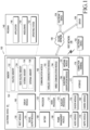
- FIG. 1 is a block diagram illustrating an electronic device 101 in a network environment 100 according to various embodiments.
- FIG. 1 is a block diagram illustrating an electronic device 101 in a network environment 100 according to various embodiments.
- the electronic device 101 in the network environment 100 may communicate with at least one of an electronic device 102 via a first network 198 (e.g., a short-range wireless communication network), or an electronic device 104 or a server 108 via a second network 199 (e.g., a long-range wireless communication network).
- the electronic device 101 may communicate with the electronic device 104 via the server 108.
- the electronic device 101 may include a processor 120, memory 130, an input module 150, a sound output module 155, a display module 160, an audio module 170, a sensor module 176, an interface 177, a connecting terminal 178, a haptic module 179, a camera module 180, a power management module 188, a battery 189, a communication module 190, a subscriber identification module (SIM) 196, or an antenna module 197.
- at least one (e.g., the connecting terminal 178) of the components may be omitted from the electronic device 101, or one or more other components may be added in the electronic device 101.
- some (e.g., the sensor module 176, the camera module 180, or the antenna module 197) of the components may be integrated into a single component (e.g., the display module 160).
- the processor 120 may execute, for example, software (e.g., a program 140) to control at least one other component (e.g., a hardware or software component) of the electronic device 101 coupled with the processor 120, and may perform various data processing or computation.
- the processor 120 may store a command or data received from another component (e.g., the sensor module 176 or the communication module 190) in volatile memory 132, process the command or the data stored in the volatile memory 132, and store resulting data in non-volatile memory 134.
- the processor 120 may include a main processor 121 (e.g., a central processing unit (CPU) or an application processor (AP)), or an auxiliary processor 123 (e.g., a graphics processing unit (GPU), a neural processing unit (NPU), an image signal processor (ISP), a sensor hub processor, or a communication processor (CP)) that is operable independently from, or in conjunction with, the main processor 121.
- a main processor 121 e.g., a central processing unit (CPU) or an application processor (AP)
- auxiliary processor 123 e.g., a graphics processing unit (GPU), a neural processing unit (NPU), an image signal processor (ISP), a sensor hub processor, or a communication processor (CP)
- the main processor 121 may be configured to use lower power than the main processor 121 or to be specified for a designated function.
- the auxiliary processor 123 may be implemented as separate from, or as part of the main processor 121.
- the auxiliary processor 123 may control at least some of functions or states related to at least one component (e.g., the display module 160, the sensor module 176, or the communication module 190) among the components of the electronic device 101, instead of the main processor 121 while the main processor 121 is in an inactive (e.g., sleep) state, or together with the main processor 121 while the main processor 121 is in an active state (e.g., executing an application).
- the auxiliary processor 123 e.g., an image signal processor or a communication processor
- the auxiliary processor 123 may include a hardware structure specified for artificial intelligence model processing.
- the artificial intelligence model may be generated via machine learning. Such learning may be performed, e.g., by the electronic device 101 where the artificial intelligence is performed or via a separate server (e.g., the server 108). Learning algorithms may include, but are not limited to, e.g., supervised learning, unsupervised learning, semi-supervised learning, or reinforcement learning.
- the artificial intelligence model may include a plurality of artificial neural network layers.
- the artificial neural network may be a deep neural network (DNN), a convolutional neural network (CNN), a recurrent neural network (RNN), a restricted Boltzmann machine (RBM), a deep belief network (DBN), a bidirectional recurrent deep neural network (BRDNN), deep Q-network or a combination of two or more thereof but is not limited thereto.
- the artificial intelligence model may, additionally or alternatively, include a software structure other than the hardware structure.
- the memory 130 may store various data used by at least one component (e.g., the processor 120 or the sensor module 176) of the electronic device 101.
- the various data may include, for example, software (e.g., the program 140) and input data or output data for a command related thereto.
- the memory 130 may include the volatile memory 132 or the non-volatile memory 134.
- the program 140 may be stored in the memory 130 as software, and may include, for example, an operating system (OS) 142, middleware 144, or an application 146.
- OS operating system
- middleware middleware
- application application
- the input module 150 may receive a command or data to be used by other component (e.g., the processor 120) of the electronic device 101, from an external environment (e.g., a user) of the electronic device 101.
- the input module 150 may include, for example, a microphone, a mouse, a keyboard, keys (e.g., buttons), or a digital pen (e.g., a stylus pen).
- the sound output module 155 may output sound signals to the outside of the electronic device 101.
- the sound output module 155 may include, for example, a speaker or a receiver.
- the speaker may be used for general purposes, such as playing multimedia or playing record.
- the receiver may be used for receiving incoming calls. According to an embodiment, the receiver may be implemented as separate from, or as part of the speaker.
- the display module 160 may visually provide information to the outside (e.g., a user) of the electronic device 101.
- the display 160 may include, for example, a display, a hologram device, or a projector and control circuitry to control a corresponding one of the display, hologram device, and projector.
- the display 160 may include a touch sensor configured to detect a touch, or a pressure sensor configured to measure the intensity of a force generated by the touch.
- the audio module 170 may convert a sound into an electrical signal and vice versa. According to an embodiment, the audio module 170 may obtain the sound via the input module 150, or output the sound via the sound output module 155 or a headphone of an external electronic device (e.g., an electronic device 102) directly (e.g., wiredly) or wirelessly coupled with the electronic device 101.
- an external electronic device e.g., an electronic device 102
- directly e.g., wiredly
- wirelessly e.g., wirelessly
- the sensor module 176 may detect an operational state (e.g., power or temperature) of the electronic device 101 or an environmental state (e.g., a state of a user) external to the electronic device 101, and then generate an electrical signal or data value corresponding to the detected state.
- the sensor module 176 may include, for example, a gesture sensor, a gyro sensor, an atmospheric pressure sensor, a magnetic sensor, an acceleration sensor, a grip sensor, a proximity sensor, a color sensor, an infrared (IR) sensor, a biometric sensor, a temperature sensor, a humidity sensor, or an illuminance sensor.
- the interface 177 may support one or more specified protocols to be used for the electronic device 101 to be coupled with the external electronic device (e.g., the electronic device 102) directly (e.g., wiredly) or wirelessly.
- the interface 177 may include, for example, a high definition multimedia interface (HDMI), a universal serial bus (USB) interface, a secure digital (SD) card interface, or an audio interface.
- HDMI high definition multimedia interface
- USB universal serial bus
- SD secure digital
- a connecting terminal 178 may include a connector via which the electronic device 101 may be physically connected with the external electronic device (e.g., the electronic device 102).
- the connecting terminal 178 may include, for example, a HDMI connector, a USB connector, a SD card connector, or an audio connector (e.g., a headphone connector).
- the haptic module 179 may convert an electrical signal into a mechanical stimulus (e.g., a vibration or motion) or electrical stimulus which may be recognized by a user via his tactile sensation or kinesthetic sensation.
- the haptic module 179 may include, for example, a motor, a piezoelectric element, or an electric stimulator.
- the camera module 180 may capture a still image or moving images.
- the camera module 180 may include one or more lenses, image sensors, image signal processors, or flashes.
- the power management module 188 may manage power supplied to the electronic device 101.
- the power management module 188 may be implemented as at least part of, for example, a power management integrated circuit (PMIC).
- PMIC power management integrated circuit
- the battery 189 may supply power to at least one component of the electronic device 101.
- the battery 189 may include, for example, a primary cell which is not rechargeable, a secondary cell which is rechargeable, or a fuel cell.
- the communication module 190 may support establishing a direct (e.g., wired) communication channel or a wireless communication channel between the electronic device 101 and the external electronic device (e.g., the electronic device 102, the electronic device 104, or the server 108) and performing communication via the established communication channel.
- the communication module 190 may include one or more communication processors that are operable independently from the processor 120 (e.g., the application processor (AP)) and supports a direct (e.g., wired) communication or a wireless communication.
- AP application processor
- the communication module 190 may include a wireless communication module 192 (e.g., a cellular communication module, a short-range wireless communication module, or a global navigation satellite system (GNSS) communication module) or a wired communication module 194 (e.g., a local area network (LAN) communication module or a power line communication (PLC) module).
- a wireless communication module 192 e.g., a cellular communication module, a short-range wireless communication module, or a global navigation satellite system (GNSS) communication module
- GNSS global navigation satellite system
- wired communication module 194 e.g., a local area network (LAN) communication module or a power line communication (PLC) module.
- LAN local area network
- PLC power line communication
- a corresponding one of these communication modules may communicate with the external electronic device 104 via a first network 198 (e.g., a short-range communication network, such as BluetoothTM, wireless-fidelity (Wi-Fi) direct, or infrared data association (IrDA)) or a second network 199 (e.g., a long-range communication network, such as a legacy cellular network, a 5G network, a next-generation communication network, the Internet, or a computer network (e.g., local area network (LAN) or wide area network (WAN)).
- a short-range communication network such as BluetoothTM, wireless-fidelity (Wi-Fi) direct, or infrared data association (IrDA)
- a second network 199 e.g., a long-range communication network, such as a legacy cellular network, a 5G network, a next-generation communication network, the Internet, or a computer network (e.g., local area network (LAN) or wide area network (WAN)).
- LAN local
- the wireless communication module 192 may identify or authenticate the electronic device 101 in a communication network, such as the first network 198 or the second network 199, using subscriber information (e.g., international mobile subscriber identity (IMSI)) stored in the subscriber identification module 196.
- subscriber information e.g., international mobile subscriber identity (IMSI)
- the wireless communication module 192 may support a 5G network, after a 4G network, and next-generation communication technology, e.g., new radio (NR) access technology.
- the NR access technology may support enhanced mobile broadband (eMBB), massive machine type communications (mMTC), or ultra-reliable and low-latency communications (URLLC).
- eMBB enhanced mobile broadband
- mMTC massive machine type communications
- URLLC ultra-reliable and low-latency communications
- the wireless communication module 192 may support a high-frequency band (e.g., the mmWave band) to achieve, e.g., a high data transmission rate.
- the wireless communication module 192 may support various technologies for securing performance on a high-frequency band, such as, e.g., beamforming, massive multiple-input and multiple-output (massive MIMO), full dimensional MIMO (FD-MIMO), array antenna, analog beamforming, or large scale antenna.
- the wireless communication module 192 may support various requirements specified in the electronic device 101, an external electronic device (e.g., the electronic device 104), or a network system (e.g., the second network 199).
- the wireless communication module 192 may support a peak data rate (e.g., 20Gbps or more) for implementing eMBB, loss coverage (e.g., 164dB or less) for implementing mMTC, or U-plane latency (e.g., 0.5ms or less for each of downlink (DL) and uplink (UL), or a round trip of 1ms or less) for implementing URLLC.
- a peak data rate e.g., 20Gbps or more
- loss coverage e.g., 164dB or less
- U-plane latency e.g., 0.5ms or less for each of downlink (DL) and uplink (UL), or a round trip of 1ms or less
- the antenna module 197 may transmit or receive a signal or power to or from other outside devices (e.g., the external electronic device).
- the antenna module 197 may include one antenna including a radiator formed of a conductor or conductive pattern formed on a substrate (e.g., a printed circuit board (PCB)).
- the antenna module 197 may include a plurality of antennas (e.g., an antenna array). In this case, at least one antenna appropriate for a communication scheme used in a communication network, such as the first network 198 or the second network 199, may be selected from the plurality of antennas by, e.g., the communication module 190.
- the signal or the power may then be transmitted or received between the communication module 190 and the external electronic device via the selected at least one antenna.
- other parts e.g., radio frequency integrated circuit (RFIC)
- RFIC radio frequency integrated circuit
- the antenna module 197 may form a mmWave antenna module.
- the mmWave antenna module may include a printed circuit board, a RFIC disposed on a first surface (e.g., the bottom surface) of the printed circuit board, or adjacent to the first surface and capable of supporting a designated high-frequency band (e.g., the mmWave band), and a plurality of antennas (e.g., array antennas) disposed on a second surface (e.g., the top or a side surface) of the printed circuit board, or adjacent to the second surface and capable of transmitting or receiving signals of the designated high-frequency band.
- a RFIC disposed on a first surface (e.g., the bottom surface) of the printed circuit board, or adjacent to the first surface and capable of supporting a designated high-frequency band (e.g., the mmWave band)
- a plurality of antennas e.g., array antennas
- At least some of the above-described components may be coupled mutually and communicate signals (e.g., commands or data) therebetween via an inter-peripheral communication scheme (e.g., a bus, general purpose input and output (GPIO), serial peripheral interface (SP1), or mobile industry processor interface (MIPI)).
- an inter-peripheral communication scheme e.g., a bus, general purpose input and output (GPIO), serial peripheral interface (SP1), or mobile industry processor interface (MIPI)
- commands or data may be transmitted or received between the electronic device 101 and the external electronic device 104 via the server 108 coupled with the second network 199.
- the external electronic devices 102 or 104 each may be a device of the same or a different type from the electronic device 101.
- all or some of operations to be executed at the electronic device 101 may be executed at one or more of the external electronic devices 102, 104, or 108. For example, if the electronic device 101 should perform a function or a service automatically, or in response to a request from a user or another device, the electronic device 101, instead of, or in addition to, executing the function or the service, may request the one or more external electronic devices to perform at least part of the function or the service.
- the one or more external electronic devices receiving the request may perform the at least part of the function or the service requested, or an additional function or an additional service related to the request, and transfer an outcome of the performing to the electronic device 101.
- the electronic device 101 may provide the outcome, with or without further processing of the outcome, as at least part of a reply to the request.
- a cloud computing, distributed computing, mobile edge computing (MEC), or client-server computing technology may be used, for example.
- the electronic device 101 may provide ultra-low-latency services using, e.g., distributed computing or mobile edge computing.
- the external electronic device 104 may include an internet-of things (IoT) device.
- the server 108 may be an intelligent server using machine learning and/or a neural network.
- the external electronic device 104 or the server 108 may be included in the second network 199.
- the electronic device 101 may be applied to intelligent services (e.g., smart home, smart city, smart car, or health-care) based on 5G communication technology or IoT-related technology.
- the electronic device may be one of various types of electronic devices.
- the electronic devices may include, for example, a portable communication device (e.g., a smart phone), a computer device, a portable multimedia device, a portable medical device, a camera, a wearable device, or a home appliance.
- a portable communication device e.g., a smart phone
- a computer device e.g., a laptop, a desktop, a smart phone
- portable multimedia device e.g., a portable multimedia device
- portable medical device e.g., a portable medical device
- camera e.g., a camera
- a wearable device e.g., a portable medical device
- a home appliance e.g., a smart bracelet
- the electronic devices are not limited to those described above.
- each of such phrases as “A or B,” “at least one of A and B,” “at least one of A or B,” “A, B, or C,” “at least one of A, B, and C,” and “at least one of A, B, or C,” may include all possible combinations of the items enumerated together in a corresponding one of the phrases.
- such terms as “1st” and “2nd,” or “first” and “second” may be used to simply distinguish a corresponding component from another, and does not limit the components in other aspect (e.g., importance or order).
- an element e.g., a first element
- the element may be coupled with the other element directly (e.g., wiredly), wirelessly, or via a third element.
- module may include a unit implemented in hardware, software, or firmware, and may interchangeably be used with other terms, for example, “logic,” “logic block,” “part,” or “circuitry”.
- a module may be a single integral component, or a minimum unit or part thereof, adapted to perform one or more functions.
- the module may be implemented in a form of an application-specific integrated circuit (ASIC).
- ASIC application-specific integrated circuit
- Certain embodiments as set forth herein may be implemented as software (e.g., the program 140) including one or more instructions that are stored in a storage medium (e.g., internal memory 136 or external memory 138) that is readable by a machine (e.g., the electronic device 101).
- a processor e.g., the processor 120
- the machine e.g., the electronic device 101
- the one or more instructions may include a code generated by a complier or a code executable by an interpreter.
- the machine-readable storage medium may be provided in the form of a non-transitory storage medium.
- non-transitory simply means that the storage medium is a tangible device, and does not include a signal (e.g., an electromagnetic wave), but this term does not differentiate between where data is semi-permanently stored in the storage medium and where the data is temporarily stored in the storage medium.
- a method according to certain embodiments of the disclosure may be included and provided in a computer program product.
- the computer program products may be traded as commodities between sellers and buyers.
- the computer program product may be distributed in the form of a machine-readable storage medium (e.g., compact disc read only memory (CD-ROM)), or be distributed (e.g., downloaded or uploaded) online via an application store (e.g., PlayStore TM ), or between two user devices (e.g., smart phones) directly. If distributed online, at least part of the computer program product may be temporarily generated or at least temporarily stored in the machine-readable storage medium, such as memory of the manufacturer's server, a server of the application store, or a relay server.
- CD-ROM compact disc read only memory
- an application store e.g., PlayStore TM
- two user devices e.g., smart phones
- each component e.g., a module or a program of the above-described components may include a single entity or multiple entities. Some of the plurality of entities may be separately disposed in different components. According to certain embodiments, one or more of the above-described components may be omitted, or one or more other components may be added. Alternatively or additionally, a plurality of components (e.g., modules or programs) may be integrated into a single component. In such a case, according to certain embodiments, the integrated component may still perform one or more functions of each of the plurality of components in the same or similar manner as they are performed by a corresponding one of the plurality of components before the integration.
- operations performed by the module, the program, or another component may be carried out sequentially, in parallel, repeatedly, or heuristically, or one or more of the operations may be executed in a different order or omitted, or one or more other operations may be added.
- FIG. 2 is a view illustrating an example configuration of an electronic device according to an embodiment.
- an electronic device 101 may include a display module 160 visually exposed to the outside on a first surface (e.g., a front surface) 210 of a housing and a camera module 180 disposed on a second surface 250 of the housing (e.g., at least one front camera 201 disposed in a portion of the first surface 210 and at least one rear camera 203 disposed on the second surface 250).
- the electronic device 101 may include an internal microphone 205 disposed on a third surface of the housing (e.g., a lower side surface with respect to the x axis).
- the internal microphone 205 may include one or more microphone elements.
- the internal microphone 205 may include three microphone elements each capable of receiving three-channel audio data.
- the processor 120 according to an embodiment may be electrically connected with the memory 130, the display module 160, the camera module 180, and the internal microphone 205.
- the processor 120 of the electronic device 101 may activate the camera module 180.
- the processor 120 may identify a video recording request, e.g., such as an input selection of an execution icon (e.g., an object, a graphic element, a menu, a button, or a shortcut image) representing the recording application displayed on the home screen (not shown) of the display module 160, depression of a designated button input, or detection a designated gesture, after which the recording application is executed.
- an execution icon e.g., an object, a graphic element, a menu, a button, or a shortcut image
- the processor 120 of the electronic device 101 may control the camera module 180 to activate at least one camera 201 or 203 to initiate video recording and control the display module 160 to display a video recording screen.
- the processor 120 may activate at least one internal microphone 205 included in the input module 150 to receive an audio signal corresponding to the sound introduced from the user, the subject, or surroundings of the subject upon video recording.
- the processor 120 may establish a communication connection over wireless communication, with an external electronic device (e.g., the external electronic device 102) including at least one external microphone 220 (e.g., a Bluetooth (BT) mic), and transmit a request to the external electronic device 102 to activate the external microphone 220 through the communication connection.
- the wireless communication may be, e.g., communication by Bluetooth (BT), Bluetooth low energy (BLE), or Wi-Fi.
- the processor 120 may directly control the wireless communication module 192 to activate the external microphone 220 or may control the wireless communication module 192 through the audio module 170 to activate the external microphone 220.
- the external microphone 220 may be a wired microphone (e.g., a USB external microphone) that communicates with the processor 120 through the connecting terminal 178.
- the processor 120 may activate the external microphone 220 through the connecting terminal 178 or may instruct the audio module 170 to activate the external microphone 220 through the connecting terminal 178 and receive an audio signal from the subject or surroundings of the subject through the external microphone 220.
- the audio signal may be received through at least one of the internal microphone 205 and the external microphone 220, transferred to the processor 120 through the audio module 170, and then synchronized and merged with the video signal collected through the camera 201 or 203 by the recording application running on the processor 120.
- a recording device for obtaining an audio signal corresponding to the sound introduced from an external environment may be implemented using the following combinations:
- the recording device may be unexpectedly switched from the external microphone 220 to the internal microphone 205, due to an interruption in communication connection between the electronic device 101 and the external microphone 220 or other issues.
- the processor 120 may recognize that the connection state between the electronic device 101 and the external microphone 220 is disrupted, and determine to switch the recording device. For example, the user may recognize that the quality of the audio signal input through the external microphone 220 is poor, and generate an input requesting a switch from the recording device to the electronic device 101.
- the recording device may be switched from the internal microphone 205 to the external microphone 220 upon new detection of a communication connection between the electronic device 101 and the external microphone 220 (or for other reasons).
- the processor 120 may determine to switch the active recording device.
- the user may recognize that the quality of the audio signal input through the internal microphone 205 is poor and generate an input requesting a switch from the recording device to the electronic device 101.
- the video signal may be continuously recorded through the camera 201 or 203 without interruption.
- recording of the audio signal may be interrupted during the switch by the electronic device 101.
- the processor 120 may insert silent audio data (e.g., silence data) into the audio signal recorded during the time in which the recording device is being switched.
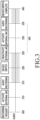
- FIG. 3 is a timing diagram illustrating the processing of audio signals including the insertion of silence data during a switch in the active recording device. Although operations performed when the recording device is switched from the external microphone 220 to the internal microphone 205 are described as an example, the opposite case may also be operated in a similar manner.
- the processor 120 may detect input of a recording request (e.g., a request for executing the camera application) by, e.g., a user input or another means (e.g., detecting the expiration of a timer or a recording event).
- the processor 120 may execute the recording application while activating at least one camera and at least one microphone (MIC) included in the camera module 180.
- the processor 120 may activate the external microphone 220 at a time 310.
- the external microphone 220 may initiate collection of audio signals, and the processor 120 may merge the collected audio signal with the video signal collected through the camera and store the combination as a multimedia video in memory.
- the processor 120 may detect device re-routing for switching the recording device.
- the recording device switch may be detected by the processor 120, e.g., upon a malfunction of the external microphone 220, or disruption in communicative connection with the external microphone 220 (which may include, e.g., disconnection).
- the processor 120 may determine to switch the recording device according to detection of a user input requesting switching of the recording device.
- the processor 120 may deactivate the external microphone 220 to process the recording device switch. As the external microphone 220 is deactivated, the audio signal may not be received any longer by the electronic device 101.
- the processor 120 may activate the internal microphone 205, and the internal microphone 205 may initiate processing for activation and, at a time 335, begin recording of an audio signal.
- the processor 120 may merge and record the audio signal collected by the internal microphone 205 and the video signal.
- the processor 120 may identify that the audio signal is normally collected by the internal microphone 205 and determine that the recording device switch has been completed.
- the processor 120 may not receive any audio signals, so that the processor 120 may insert silence data during the time period 345.
- the processor 120 may insert the silence data between the audio signal before the time 325 and the audio signal before the time 335.
- the audio signal including the silence data may be merged with the video signal in the period by the recording application executed on the processor 120.
- the processor 120 may set a frame count for video and audio (hereinafter, referred to as video/audio) data including the video signal and the audio signal.
- the vehicle may set a frame count that is increased by one for each frame in the video/audio data input during video recording, identify a first frame count at the time 325, which is before the recording device switch, and a second frame count at the time 335, which is after the recording device switch, and insert silence data to the video/audio data between the first frame count and the second frame count.
- the processor 120 may record the time stamp at the time 325 when the external microphone 220 is deactivated, record the time stamp at the time 335 when the audio signal recording begins by the internal microphone 205, and measure the time between the times 325 and 335 using the time stamps.
- the processor 120 may generate the audio signal to which as much silence data as measured has been inserted and merge the silence data-containing audio signal with the video signal.
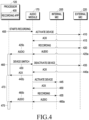
- FIG. 4 is a signal flow diagram illustrating processing of audio signals due to insertion of silence data.
- the processor 120 may transfer a recording start signal to the audio module 170 when the recording application 400 is executed.
- the audio module 170 may be implemented using an audio framework software module included in the processor 120, and the recording start signal may be transferred from the recording application 400 to the audio framework software module.
- the audio module 170 may transmit a device activation signal to the external microphone 220 and, in operation 415, the audio module 170 may receive a response (ACK) signal indicating that the external microphone 220 has been successfully activated in response to the device activation signal.
- ACK response
- the audio module 170 may detect connection of the external microphone 220 through the wireless communication module 192 or the connecting terminal 178 and transmit the device activation signal to the external microphone 220.
- the processor 120 may detect connection of the external microphone 220 through the wireless communication module 192 or connecting terminal 178 and include information, for instructing the audio module 170 to transmit the device activation signal to the external microphone 220, in the recording start signal.
- the audio module 170 may detect non-connection of the external microphone 220 through the wireless communication module 192 or the connecting terminal 178, and transmit the device activation signal to the internal microphone 205.
- the processor 120 may detect non-connection of the external microphone 220 through the wireless communication module 192 or the connecting terminal 178 and include information, for instructing the audio module 170 to transmit the device activation signal to the internal microphone 205, in the recording start signal.
- the audio module 170 may transmit a recording signal to the external microphone 220, in operation 425a, receive the audio signal including the audio data collected by the external microphone 220, and in operation 425b, transmit the audio signal to the processor 120.
- the processor 120 may record the audio signal.
- the processor 120 may merge the audio signal with the video signal received through the camera and store it or output it on the screen.
- the processor 120 may determine to switch the recording device and transmit a device switch signal to the audio module 170.
- the recording device switch may be determined when the processor 120, for example, detects a poor communication state of the external microphone 220 through the wireless communication module 192 or the connecting terminal 178 (e.g., when a signal strength is below a predetermined threshold).
- the recording device switch may be determined as the processor 120 receives a user input requesting to switch the microphone.
- the audio module 170 may transmit a device deactivation signal to the external microphone 220 and, in operation 440a, receive a response signal indicating that device deactivation has been completed.
- the audio module 170 may transmit the device activation signal to the internal microphone 205 and, in operation 450, receive a response signal indicating that the internal microphone 205 has been successfully activated.
- the audio module 170 may transmit a recording signal to the internal microphone 205, in operation 460a, receive the audio signal including the audio data collected by the internal microphone 205, and in operation 460b, transmit the audio signal to the processor 120.
- the audio module 170 may transfer, to the processor 120, a signal indicating that the external microphone 220 has been deactivated in operation 440b.
- the processor 120 may generate an audio signal including silence data from the time of operation 440b in which the deactivation of the external microphone 220 is recognized to the time of operation 460b in which the audio signal collected through the internal microphone 205 is received. The generated audio signal may be used to be merged with the video signal.
- the processor 120 may stop generation of the silence data-containing audio signal and merge the audio signal collected through the internal microphone 205 with the video signal.
- FIG. 5 is a timing diagram illustrating processing of audio signals when a recording device is switched according to an embodiment. Although operations performed when the recording device is switched from the external microphone 220 to the internal microphone 205 are described, the opposite case may also be operated in a similar manner.
- the processor 120 of the electronic device 101 may detect a recording request by, e.g., a user input or another means. In response to the recording request, the processor 120 may execute the recording application while activating at least one camera and at least one microphone included in the camera module 180. In an embodiment, according to detection of connection of the external microphone 220 to the electronic device 101, the processor 120 may activate the external microphone 220 at a time 510. At a time 515, the external microphone 220 may begin receive of an audio signal, and the processor 120 may merge the received audio signal with the video signal received through the camera and record it to memory.
- the processor 120 may detect device re-routing for switching the recording device.
- the recording device switch may be detected by the processor 120, e.g., due to a malfunction of the external microphone 220, or a connection failure between the electronic device 101 and the external microphone 220, etc.
- the processor 120 may determine to switch the recording device according to detection of a user input to request for switching the recording device.
- the processor 120 may activate the internal microphone 205 to process the recording device switch.
- the external microphone 220 however is still active here (as per 530).
- the audio signal from the still-active external microphone 220 and the audio signal from the activated internal microphone 205 may both be received by the electronic device 101.
- the processor 120 may begin mixing the audio signal from the internal microphone 205 and the audio signal from the internal microphone 205. At a time 535, until activation of the internal microphone 205 is normally completed, the processor 120 may continue to perform mixing processing on the audio signals. Thereafter, at a time 540, the processor 120 may deactivate the external microphone 220, thereby completing the switching process. Then, the mixing process may be finished.
- the processor 120 may mix the audio signal from the internal microphone 205 and the audio signal from the external microphone 220 from the time 525 when the internal microphone 205 is activated to the time 540 when the external microphone 220 is deactivated and record the mixed audio signals. As such, the processor 120 may maintain the input of the audio signal while the recording device switch is performed, preventing audio loss in recording.
- FIG. 6 is a block diagram illustrating a configuration of an electronic device 101 that processes audio signals when a recording device is switched according to certain embodiments.
- an electronic device 101 may include a processor 120 and an input module 150 including at least one internal microphone 205.
- the electronic device 101 may establish a wired communication-based or wireless communication-based communication connection with an external electronic device 102 including at least one external microphone 220 and may communication a control signal (e.g., an activation signal or a deactivation signal) for the external microphone 220 through the communication connection or receive a first audio signal from the external microphone 220.
- a control signal e.g., an activation signal or a deactivation signal
- the processor 120 may include a device switch requesting unit 605, a device managing unit 610, a sync (synchronizing) processing unit 615, a switch processing unit 620, a channel mixing unit 625, and a device state determining unit 630.
- the device switch requesting unit 605 may be included in a recording application executed by the processor 120.
- the device managing unit 610, the sync processing unit 615, the switch processing unit 620, the channel mixing unit 625, and the device state determining unit 630 may be included in audio framework implemented by the processor 120.
- at least one of the device managing unit 610, the sync processing unit 615, the switch processing unit 620, the channel mixing unit 625, and the device state determining unit 630 may be included in the audio module 170.
- the external microphone 220 may be active, and the internal microphone 205 may be inactive.
- the first audio signal collected by the external microphone 220 may be input to the device managing unit 610 of the processor 120. If the device switch requesting unit 605 determines to switch the recording device and notifies the device managing unit 610 of it, the device managing unit 610 may transmit an activation signal to the internal microphone 205. In response to the activation signal, the internal microphone 205 may be activated, and the second audio signal collected by the internal microphone 205 may start to be input to the device managing unit 610 of the processor 120. In an embodiment, the internal microphone 205 and the external microphone 220 both may be active.
- the device managing unit 610 may select and output the first audio signal from the external microphone 220, of the active internal microphone 205 and the active external microphone 220. If notified of the recording device switch, the device managing unit 610 may output both the first audio signal from the external microphone 220 and the second audio signal from the internal microphone 205.
- the first and second audio signals may be synchronized.
- the sync processing unit 615 may synchronize them by compensating for the time difference between the second audio signal input from the internal microphone 205 and the first audio signal input from the external microphone 220.
- the sync processing unit 615 may synchronize the first audio signal and the second audio signal by delaying the second audio signal input from the internal microphone 205 by a designated delay value.
- the device state determining unit 630 may receive, from the device managing unit 610, a signal indicating that the internal microphone 205 is active and transfer the signal to the switch processing unit 620. In response to reception of the signal, the switch processing unit 620 cross-fades the first audio signal and the delayed second audio signal transferred from the sync processing unit 615. In an embodiment, the switch processing unit 620 may correct at least one of the first audio signal and the second audio signal to reduce the volume differential between the first audio signal of the external microphone 220 and the delayed second audio signal of the internal microphone 205 using root means square (RMS) dynamic range control (DRC) so as to smoothly process the switch from the external microphone 220 to the internal microphone 205.
- RMS root means square
- DRC dynamic range control
- the switch processing unit 620 may cross-fade the first audio signal and the delayed second audio signal during a designated time period (e.g., a designated number of, one or more, frames).
- the cross-fading may include an operation of gradually increasing the volume of the delayed second audio signal through fade-in processing and an operation of gradually decreasing the volume of the first audio signal through fade-out processing during the designated time period.
- the length of the designated time period may be previously determined by the manufacturer of the electronic device 101 or may be determined by measurement in the processor 120.
- the channel mixing unit 625 may mix the fade-in-processed second audio signal and the fade-out-processed first audio signal, generating mixed audio signals.
- the mixed audio signals may be recorded or merged with the video signal recorded by the camera.
- the internal microphone 205 Before the recording device switch, the internal microphone 205 may be active, and the external microphone 220 may be inactive. While a third audio signal obtained by the internal microphone 205 is received, the device switch requesting unit 605 may determine to switch the recording device and notify the device managing unit 610 of it. In response to the notification, the device managing unit 610 may transmit an activation signal to the external microphone 220. In response to the activation signal, the external microphone 220 may be activated, and the fourth audio signal collected by the external microphone 220 may start to be input to the device managing unit 610 of the processor 120.
- the sync processing unit 615 may synchronize them by compensating for the time difference between the third audio signal input from the internal microphone 205 and the fourth audio signal input from the external microphone 220. In an embodiment, the sync processing unit 615 may delay the third audio signal by a designated delay value.
- the switch processing unit 620 may cross-fade the delayed third audio signal and the fourth audio signal transferred from the sync processing unit 615 during a designated time period.
- the delayed third audio signal may be fade-out-processed
- the fourth audio signal may be fade-in-processed.
- the channel mixing unit 625 may mix the fade-in-processed second audio signal and the fade-out-processed first audio signal, generating mixed audio signals.
- the mixed audio signals may be recorded or merged with the video signal recorded by the camera. If the designated time period terminates, the device managing unit 610 may transmit a deactivation signal to the internal microphone 205.
- an electronic device 101 may include an internal microphone 205, a communication module 190, and at least one processor 120 operatively connected with the internal microphone and the communication module.
- the at least one processor may be configured to receive, through the communication module, a first audio signal input through an external microphone 220 included in an external electronic device 102 communicatively connected to the electronic device, activate the internal microphone in response detecting a device switch event switching from the external microphone to the internal microphone while receiving the first audio signal, receive a second audio signal input through the internal microphone, synchronize and mix the first audio signal and the second audio signal during a designated first time period, and deactivate the external microphone upon detecting lapse of the designated first time period.
- the at least one processor may be configured to delay the second audio signal by a designated delay value, wherein mixing the first audio signal and the delayed second audio signal includes applying cross-fading during the designated first time period.
- the at least one processor may be configured to correct at least one of the first audio signal and the delayed second audio signal to at least reduce a volume differential between the first audio signal and the delayed second audio signal before mixing the first audio signal and the delayed second audio signal.
- correcting at least one of the delayed second audio signal and the first audio signal further includes using root mean square (RMS) dynamic range compression (DRC).
- RMS root mean square
- DRC dynamic range compression
- the at least one processor may be configured to merge the mixed first and second audio signals with a first video signal corresponding to the designated first time period.
- the at least one processor may be configured to store a third audio signal received through the external microphone in a recovery buffer, activate the internal microphone in response to detection of disconnection of the external electronic device from the electronic device, after detecting the disconnection, retrieve the third audio signal from the recovery buffer, mix a fourth audio signal input through the internal microphone with the third audio signal obtained from the recovery buffer during a designated second time period, and merge the mixed fourth and third audio signals with a second video signal corresponding to the second time period.
- the at least one processor may be configured to delay the fourth audio signal by a designated delay value, correct at least one of the third audio signal and the delayed fourth audio signal to at least reduce a volume differential between the third audio signal and the delayed fourth audio signal, mix the corrected third audio signal and fourth audio signal through cross-fading during the second time period, and terminate output of the third audio signal from the recovery buffer upon lapse of the designated second time period.
- the at least one processor may be configured to obtain a fifth audio signal received through the internal microphone, transmit a signal to the external electronic device to activate the external microphone while obtaining the fifth audio signal, obtain a sixth audio signal received through the external microphone, synchronize the fifth audio signal and the sixth audio signal, mix the synchronized fifth audio signal and sixth audio signal during a designated second time period, and deactivate the internal microphone upon lapse of the designated second time period.
- the at least one processor may be configured to delay the fifth audio signal by a designated delay value, correct at least one of the delayed fifth audio signal and the sixth audio signal to at least reduce a volume differential between the delayed fifth audio signal and the sixth audio signal, and mix the corrected fifth audio signal and sixth audio signal using at least cross-fading during the second time period.
- the at least one processor may be configured to store a seventh audio signal received through the internal microphone in a recovery buffer, transmit a signal to the external electronic device to activate the external microphone, retrieve the seventh audio signal from the recovery buffer, correct at least one of an eighth audio signal input through the external microphone and the seventh audio signal obtained from the recovery buffer to at least reduce a volume differential between the eighth audio signal and the seventh audio signal, mix the corrected seventh audio signal and eighth audio signal using at least cross-fading during a designated third time period, merge the mixed seventh and eighth audio signals with a second video signal corresponding to the third time period, and terminate output of the seventh audio signal from the recovery buffer upon lapse of the designated third time period.
- FIG. 7 is a flowchart illustrating a procedure 700 for processing audio signals when a recording device is switched according to certain embodiments.
- the processor 120 may record the audio signal input via an activated first microphone.
- the first microphone may be either the internal microphone 205 included in the electronic device 101 or the external microphone 220 included in the external electronic device 102.
- the processor 120 may determine to switch the recording device from the first microphone to a second microphone.
- the second microphone may be a microphone different from the first microphone, which may be included in the electronic device 101 or connected to the electronic device 101.
- the first microphone is the internal microphone 205
- the second microphone may be the external microphone 220.
- the first microphone may be the internal microphone 205.
- the processor 120 may activate the second microphone.
- the processor 120 may mix the first audio signal received from the first microphone with the second audio signal received from the second microphone during a designated time period.
- the first audio signal may be processed with a fade-out effect before mixing
- the second audio signal may be processed to include a fade-in before mixing.
- the processor 120 may stepwise decrease the volume of the first audio signal, and stepwise increase the volume of the second audio signal. The fade-out-processed first audio signal and the fade-in-processed second audio signal may thus be mixed.
- the processor 120 may execute the recording application including a video and, when a video signal is received through the camera during the designated time period, merge the mixed audio signals with the video signal.
- the processor 120 may deactivate the first microphone, completing the switch.
- FIG. 8 is a flowchart illustrating an operation 720 of mixing audio signals according to certain embodiments.
- the processor 120 may receive the first audio signal and the second audio signal, and delay either the first audio signal or the second audio signal (e.g., the second audio signal from the internal microphone 205), by a designated delay value. In an embodiment, the processor 120 may delay the second audio signal by the delay value, on a frame by frame basis.
- the processor 120 may correct the delayed second audio signal and the first audio signal to reduce a volume differential between the delayed second audio signal and the first audio signal.
- the processor 120 may use an RMS DRC scheme for correction.
- the RMS DRC scheme may detect a first RMS value indicating the volume of the first audio signal, and a second RMS value indicating the volume of the delayed second audio signal.
- the processor 120 may compare the first RMS and the second RMS. For example, when the first RMS is larger, the processor 120 may reduce the volume of the first audio signal to be equal, or at least similar, to the volume of the delayed second audio signal using a DRC scheme. Conversely, when the second RMS is larger, the processor 120 may reduce the volume of the delayed second audio signal to be equal, or at least similar, to the volume of the first audio signal using the DRC scheme.
- the processor 120 may process the corrected first audio signal to incorporate a fade-out effect, and process the corrected second audio signal to incorporate a fade-in effect.
- the fade-out-processing may include an operation of stepwise reducing the volume of the corrected first audio signal during the designated time period.
- the fade-in-processing may include an operation of stepwise increasing the volume of the corrected second audio signal during the designated time period.
- the processor 120 may mix the fade-out-processed first audio signal and the fade-in-processed second audio signal during the designated time period.
- the mixed audio signals may be merged with the corresponding video signal and be then stored or output.
- FIG. 9 is a block diagram illustrating an implementation example of a processor 120 for processing a recording device switch according to certain embodiments.
- a processor 120 may include a recording application 400 and an audio processing module 910.
- the audio processing module 910 may be implemented as audio framework software implemented as an audio hardware abstraction layer (HAL).
- the audio processing module 910 may be implemented as the audio module 170 instead of being included in the processor 120.
- the external microphone 220 may be connected to the processor 120 through an audio interface 925.
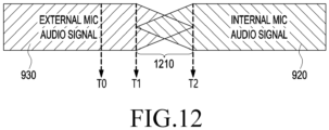
- the first audio signal 930 from the external microphone 220 may include one-channel audio data and be transferred through the audio interface 925 to the audio processing module 910.
- the internal microphone 205 may be connected to the processor 120 through an audio interface 915.
- the second audio signal 920 from the internal microphone 220 may include three-channel audio data and be transferred through the audio interface 915 to the audio processing module 910.
- the audio processing module 910 may receive at least one of the first audio signal 930 from the external microphone 220 and the second audio signal 920 from the internal microphone 205.
- the audio processing module 910 may include a device managing module 935, which manages connections with the external microphone 220 and the internal microphone 205, and manages each device state, and a recording synthesizing module 940, which processes and mixes the audio signals.
- a device managing module 935 which manages connections with the external microphone 220 and the internal microphone 205, and manages each device state
- a recording synthesizing module 940 which processes and mixes the audio signals.
- a device switch from the external microphone 220 to the internal microphone 205 is described.
- the recording application 400 may detect a device switch event to switch audio recording devices, and transfer the device switch event to the device managing module 935.
- the processor 120 may receive a request for switching the recording device by the user and generate a device switch event through the recording application 400.
- the processor 120 may determine that a recording device switch is to be executed due to an issue with connection with the external microphone 220, or other issues (described elsewhere in the disclosure), and generate a device switch event through the recording application 400.
- the device managing module 935 may activate the internal microphone 205 in response to the device switch event.
- the external microphone 220 and the internal microphone 205 both are activated, and the first audio signal 930 from the external microphone 220 and the second audio signal 920 from the internal microphone 205 are both input to the recording synthesizing module 940 through the device managing module 935.
- the recording synthesizing module 940 may mix the first audio signal 930 and the second audio signal 920 during a designated time period, and transfer the mixed audio signals through a pulse code modulation (PCM) node 985 to the recording application 400.
- PCM pulse code modulation
- the recording application 400 may merge the mixed audio signals with the video signal, which is input through a camera (not shown) and which corresponds to the designated time period, and record the same to memory.
- the recording synthesizing module 940 may include a delay buffer 945, a switching module 955, and a mixer 975.
- the recording synthesizing module 940 may further include a channel mixer 950 and a state module 980.
- the delay buffer 945 may delay either the first audio signal 930 or the second audio signal 920 input through the device managing module 935 by a designated delay value.
- the delay buffer 945 may delay the first audio signal 930 from the external microphone 220 by a designated delay value and output a delayed first audio signal.
- the delay value may correspond to the input time difference between the external microphone 220 and the internal microphone 205 and may be measured by the processor 120 or previously determined by the manufacturer.
- the delayed first audio signal output from the delay buffer 945 may include three-channel data and may be converted into an audio signal including two-channel audio by the channel mixer 950.
- the audio signal from the channel mixer 950 is input to the switching module 955.
- the switching module 955 may include a DRC module 965 and a cross-fading module 970 and, optionally, may further include a recovery buffer 960.
- the recovery buffer 960 may store the audio signal, which is input from the channel mixer 950, and/or the audio signal, which is input via the delay buffer 945, by each designated length.
- Each audio signal stored in the recovery buffer 960 may be used to mix with another audio signal when an actual audio signal is not normally received due to a failure in each microphone or disconnection.
- the purpose of the recovery buffer 960 is described below in detail.
- the DRC module 965 may receive the audio signal corresponding to the internal microphone 205 and the audio signal corresponding to the external microphone 220, which are input through the recovery buffer 960, and perform an RMS DRC operation by referencing device information about the internal microphone 205 and the external microphone 220 received from the state module 980 to thereby correct the volume difference between the audio signals and output the corrected first audio signal and the corrected second audio signal.
- the device information may include information about the volumes of the internal microphone 205 and the external microphone 220.
- the cross-fading module 970 may receive the corrected first audio signal and the corrected second audio signal from the DRC module 965 and cross-fade the corrected first audio signal and the corrected second audio signal during a designated time period.
- the cross-fading may include fade-out-processing of the corrected first audio signal corresponding to the external microphone 220, and fade-in-processing of the corrected second audio signal corresponding to the internal microphone 205.
- the mixer 975 may mix the fade-out-processed first audio signal and the fade-in-processed second audio signal received from the cross-fading module 970.
- the mixed audio signals may include two-channel audio data.
- the mixed audio signals may be transferred to the recording application 400 through the PCM node 985 and then stored.
- the recording application 400 may merge the mixed audio signals with the corresponding video signal and store it.
- the device managing module 935 may deactivate the external microphone 220 and transfer a signal indicating that the external microphone 220 is inactive to the switching module 955, terminating the audio mixing operation for recording device switch processing. Thereafter, the second audio signal from the internal microphone 205 may be input through the audio processing module 910 to the recording application 400.
- a device switch from the internal microphone 205 to the external microphone 220 is described.
- the recording application 400 may detect a device switch event to switch audio recording devices, and transfer the device switch event to the device managing module 935.
- the processor 120 may receive a request for switching the recording device by the user and generate a device switch event through the recording application 400.
- the processor 120 may detect connection of the external microphone 220 to the electronic device 101 and generate a device switch event through the recording application 400.
- the device managing module 935 may activate the external microphone 220 in response to the device switch event.
- the external microphone 220 and the internal microphone 205 both are activated, and the second audio signal from the external microphone 220 and the first audio signal from the internal microphone 205 are input to the recording synthesizing module 940 through the device managing module 935.
- the recording synthesizing module 940 may mix the first audio signal and the second audio signal during a designated time period and transfer the mixed audio signals through a pulse code modulation (PCM) node 985 to the recording application 400.
- PCM pulse code modulation
- the recording application 400 may merge the mixed audio signals with the video signal, which is input through a camera (not shown) and corresponds to the designated time period, and record it.
- the device managing module 935 may deactivate the internal microphone 205 and transfer a signal indicating that the internal microphone 205 is inactive to the switching module 955, terminating the audio mixing operation for recording device switch processing.
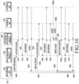
- FIG. 10 is a signal flow diagram illustrating a mixing process of audio signals when a recording device is switched according to certain embodiments.
- a processor 120 may include a recording application 400, a device managing module 935, and a recording synthesizing module 940.
- the recording application 400 of the processor 120 may transfer a recording start signal to the device managing module 935.
- the recording start signal may be generated as the recording application 400 is executed.
- the recording start signal may be generated as the recording application 400 detects that recording should be initiated.
- the device managing module 935 may transmit a device activation signal to the external microphone 220 and, in operation 1015, the audio module 170 may receive a response (ACK) signal indicating that the external microphone 220 has been successfully activated in response to the device activation signal.
- the device managing module 935 may detect connection of the external microphone 220 through the wireless communication module 192 or the connecting terminal 178 and transmit the device activation signal to the external microphone 220.
- the device activation signal may be transferred to the recording synthesizing module 940 and, in operation 1015, the recording synthesizing module 940 may transmit a response signal to the device managing module 935.
- the recording synthesizing module 940 may recognize that the external microphone 220 is activated.
- the device managing module 935 may detect non-connection of the external microphone 220 through the wireless communication module 192 or the connecting terminal 178 and transmit the device activation signal to the internal microphone 205 and the recording synthesizing module 940.
- the device managing module 935 may transmit the recording signal to the external microphone 220 and the recording synthesizing module 940.
- the recording synthesizing module 940 may prepare for processing for the audio signal received from the external microphone 220.
- the audio signal including the audio data collected by the external microphone 220 may go through appropriate processing by the recording synthesizing module 940, and may then be transferred to the recording application 400.
- the recording application 400 may record the audio signal or merge it with a corresponding video signal and store it.
- the recording application 400 may determine to switch the recording device and transmit a device switch signal to the device managing module 935.
- the recording device switch may be determined as the recording application 400 detects a poor communication state of the external microphone 220 through the wireless communication module 192 or the connecting terminal 178.
- the recording device switch may be determined as the recording application 400 receives a user input for requesting to switch the microphone.
- the device managing module 935 may transmit a device activation signal to the internal microphone 205 and, in operation 1040, receive a response signal indicating that the internal microphone 205 has been successfully activated.
- the device activation signal may be transferred to the recording synthesizing module 940.
- the recording synthesizing module 940 may recognize that the internal microphone 205 is activated and transmit a response signal to the device managing module 935.
- the device managing module 935 may transmit the recording signal to the internal microphone 205 and the recording synthesizing module 940.
- the recording synthesizing module 940 may prepare for processing of the audio signal received from the internal microphone 205.
- the device managing module 935 may transmit the recording signal to the external microphone 220 and the recording synthesizing module 940.
- the first audio signal including the audio data collected by the external microphone 220 may be received by the recording synthesizing module 940 and, in operation 1055b, the second audio signal including the audio data collected by the internal microphone 205 may be received by the recording synthesizing module 940.
- the recording synthesizing module 940 may mix the first audio signal and the second audio signal applying the synchronization, volume correction, and cross-fade mixing processes according to operation 805 of FIG. 8 .
- the mixed audio signals may be transmitted from the recording synthesizing module 940 to the recording application 400.
- the recording application 400 may merge the audio signal from the external microphone 220 with the video signal during the time period 1085 from the time when the audio signal starts to be received from the external microphone 220 in operation 1025, to the time when the mixed audio signals are received in operation 1065. During a designated time period 1090 after the mixed audio signals begin to be received in operation 1065, the recording application 400 may merge the mixed audio signals, including the first audio signal from the external microphone 220 and the second audio signal from the internal microphone 205, with the video signal.
- the device managing module 935 may transmit a device deactivation signal to the external microphone 220 and the recording synthesizing module 940.
- the device deactivation signal may be transmitted after a designated time period after activating the internal microphone 205 in operation 1035. The designated time period may be determined considering the time period 1090 during which the first audio signal and the second audio signal are mixed and the time to activate the internal microphone 205.
- a response signal indicating that the external microphone 220 has been deactivated may be received by the recording synthesizing module 940 and the device managing module 935.
- the device managing module 935 may transmit a response signal indicating that the external microphone 220 has been deactivated to the recording application 400.
- the device managing module 935 may transmit a recording signal to the internal microphone 205 and the recording synthesizing module 940 and, in operation 1080, the audio signal collected by the internal microphone 205 may be transferred through the recording synthesizing module 940 to the recording application 400.
- the recording application 400 may merge the audio signal from the internal microphone 205 with the video signal.
- FIG. 11 is a view illustrating synchronization processing for audio signals of an internal microphone and an external microphone, according to an embodiment.
- the first audio signal 930 input by the external microphone 220 may include one-channel audio data
- the second audio signal 920 input by the internal microphone 205 may include three-channel audio data.
- the first audio signal 930 may be delayed by a predetermined time 1120 from the second audio signal 920 and input to the electronic device 101.
- the predetermined time 1120 may be 80ms, which may be a value measured by the processor 120 or determined by the manufacturer of the electronic device 101.
- the processor 120 may store the second audio signal 920 in the delay buffer 945 before the mixing processing (e.g., the input of the switching module 955) and delay it by a predetermined value, e.g., 80ms (1120), and then output it, thereby synchronizing it with the first audio signal 930.
- a predetermined value e.g. 80ms (1120
- FIG. 12 is a view illustrating a cross-fade mixing process for audio signals of an internal microphone and an external microphone, according to an embodiment.
- the processor 120 may detect a device switch event. In response to the device switch event, at time T1, the processor 120 may activate the internal microphone 205 and start to receive the second audio signal 920 from the activated internal microphone 205. During a designated time period 1210 from time T1, the processor 120 may perform DRC processing (e.g., 965) and fade-out-processing (e.g., 970) on the first audio signal 930.
- DRC processing e.g., 965
- fade-out-processing e.g., 970
- the processor 120 may perform delay processing (e.g., 945), DRC processing (e.g., 965), and fade-in-processing (e.g., 970) on the second audio signal 920.
- delay processing e.g., 945
- DRC processing e.g., 965
- fade-in-processing e.g., 970
- the processor 120 may deactivate the external microphone 220, so that the input of the second audio signal 930 and the fade-out-processing of the first audio signal 930 may be stopped and, after time T2, the audio signal from the internal microphone 205 may be exclusively input.
- FIG. 13 is a flowchart illustrating a procedure for processing audio signals when a recording device is disconnected according to certain embodiments.
- the processor 120 may record the first audio signal input through the active first microphone while simultaneously buffering the first audio signal.
- the first microphone may be either the internal microphone 205 included in the electronic device 101 or the external microphone 220 included in the external electronic device 102.
- the first audio signal may be stored in a recovery buffer (e.g., 960) included in the electronic device 101.
- the recovery buffer 960 may buffer the first audio signal by each designated length while the first audio signal is input.
- the recovery buffer 960 may be configured to store the first audio signal, at least, by the length utilized for mixing processing described below.
- the processor 120 may determine that an operation stop is detected due to operational failure in the first microphone or disconnection of the same.
- the first microphone may be the external microphone 220 included in the external electronic device 102, and the processor 120 may determine whether connection with the external microphone 220 is disrupted through the wireless communication module 192 or the connecting terminal 178.
- the first microphone may be the internal microphone 205 included in the electronic device 101, and the processor 120 may determine that the operation of the internal microphone 205 has become abnormal, based on a user input or internal determination.
- the processor 120 may activate the second microphone.
- the second microphone may be different from the first microphone, which may be included in the electronic device 101 or connected to the electronic device 101.
- the processor 120 may output the first audio signal stored in the recovery buffer 960 and, in operation 1325, mix the first audio signal read from the recovery buffer 960 and the second audio signal input from the second microphone during a designated time period.
- the recovery buffer 960 may store the first audio signal, at least, by the same length as the designated time period.
- the first audio signal and the second audio signal may be synchronized before mixing.
- the synchronizing may include an operation of delaying at least one of the first audio signal and the second audio signal by a predetermined delay value.
- the first audio signal may be fade-out-processed before mixing
- the second audio signal may be fade-in-processed before mixing.
- the processor 120 may stepwise decrease the volume of the first audio signal and stepwise increase the volume of the second audio signal.
- the fade-out-processed first audio signal and the fade-in-processed second audio signal may be mixed.
- the mixed audio signals may be merged with the video signal input through the camera and recorded.
- the processor 120 may determine whether the designated time period has lapsed (i.e., is terminated). During the designated time period, the processor 120 may perform the mixing of operation 1325. If the designated time period is terminated, the processor 120 may terminate the mixing and exclusively record the second audio signal in operation 1335.
- the first audio signal 930 may be stored in the recovery buffer 960 of the recording synthesizing module 940 by each predetermined length.
- the recording application 400 may detect that the external microphone 220 stops operating due to a user input, disconnection, or other causes and transfer a device switch event to the device managing module 935.
- the device managing module 935 may activate the internal microphone 205 in response to the device switch event.
- the second audio signal 920 from the active internal microphone 205 is input through the device managing module 935 to the recording synthesizing module 940.
- the second audio signal is delayed by a predetermined delay value by the delay buffer 945 in the recording synthesizing module 940 and then, as desired, is converted to include two-channel audio data by the channel mixer 950 and is then input to the switching module 955.
- the device managing module 935 may notify the switching module 955 that the operation of the external microphone 220 has stopped through the state module 980.
- the switching module 955 may read the first audio signal 930 stored in the recovery buffer 960, and the first audio signal 930, together with the second audio signal delayed through the delay buffer 945, is transferred to the DRC module 965.
- the DRC module 965 may receive the first audio signal 930, which is read from the recovery buffer 960 and corresponds to the external microphone 220, and the second audio signal, which is input from the delay buffer 945 and corresponds to the internal microphone 205, and perform an RMS DRC operation on the first audio signal 930 and the delayed second audio signal to thereby correct the volume difference between the audio signals and output the corrected first audio signal and the corrected second audio signal.
- the cross-fading module 970 may receive the corrected first audio signal and the corrected second audio signal from the DRC module 965 and cross-fade the corrected first audio signal and the corrected second audio signal during a designated time period.
- the cross-fading may include fade-out-processing of the corrected first audio signal corresponding to the external microphone 220 and fade-in-processing of the corrected second audio signal corresponding to the internal microphone 205.
- the mixer 975 may mix the fade-out-processed first audio signal and the fade-in-processed second audio signal received from the cross-fading module 970.
- the mixed audio signals may include two-channel audio data.
- the mixed audio signals may be transferred to the recording application 400 through the PCM node 985 and then stored.
- the recording application 400 may merge the mixed audio signals with the corresponding video signal and store it.
- the device managing module 935 may transfer a signal indicating that the device switch has been completed to the switching module 955, terminating the audio signal output from the recovery buffer 960 and the audio mixing operation for recording device switch processing.
- a method of operation in an electronic device may include receiving, through a communication module, a first audio signal input through an external microphone included in an external electronic device communicatively coupled to the electronic device, activating an internal microphone in response detecting a device switch event switching from the external microphone to the internal microphone while receiving the first audio signal, receiving a second audio signal input through the internal microphone, synchronizing and mixing, via at least one processor, the first audio signal and the second audio signal during a designated first time period, and deactivating the external microphone if the designated time period terminates.
- the mixing may further include delaying the second audio signal by a designated delay value and cross-fading the first audio signal and the delayed second audio signal during the designated first time period.
- the method may further include correcting the first audio signal and the delayed second audio signal to at least reduce a volume differential between the first audio signal and the delayed second audio signal prior to mixing the first audio signal and the delayed second audio signal.
- correcting the first audio signal and the delayed second audio signal may further include applying root mean square (RMS) dynamic range compression (DRC).
- RMS root mean square
- DRC dynamic range compression
- the method may further include merging the mixed first and second audio signals with a first video signal corresponding to the designated first time period.
- the method may further include storing a third audio signal received through the external microphone in a recovery buffer, activating the internal microphone in response detecting of disconnection of the external electronic device from the electronic device, retrieving the third audio signal from the recovery buffer, mixing a fourth audio signal input through the internal microphone with the third audio signal retrieved from the recovery buffer during a designated second time period, and merging the mixed fourth and third audio signals with a second video signal corresponding to the second time period.
- the mixing may include delaying the fourth audio signal by a designated delay value, correcting at least one of the third audio signal and the delayed fourth audio signal to at least reduce a volume differential between the third audio signal and the delayed fourth audio signal, mixing the corrected third audio signal and fourth audio signal using at least cross-fading during the second time period, and terminating output of the third audio signal from the recovery buffer upon detecting lapse of the designated second time period.
- the method may further include receiving a fifth audio signal input through the internal microphone, transmitting a signal to the external electronic deivce to activate the external microphone while receiving the fifth audio signal, receiving a sixth audio signal input through the external microphone, synchronizing the fifth audio signal and the sixth audio signal, mixing the synchronized fifth audio signal and sixth audio signal during a designated second time period, and deactivating the internal microphone upon detecting lapse of the designated second time period.
- the mixing may include delaying the fifth audio signal by a designated delay value, correcting at least one of the delayed fifth audio signal and the sixth audio signal to at least reduce a volume differential between the delayed fifth audio signal and the sixth audio signal, and mixing the corrected fifth audio signal and sixth audio signal using at least cross-fading during the second time period.
- the method may further include storing a seventh audio signal received through the internal microphone in a recovery buffer, transmitting a signal to the external electronic device to activate the external microphone, retrieving the seventh audio signal from the recovery buffer, correcting at least one of an eighth audio signal received through the external microphone and the seventh audio signal retrieved from the recovery buffer to at least reduce a volume differential between the eighth audio signal and the seventh audio signal, mixing the corrected seventh audio signal and eighth audio signal using at least cross-fading during a designated third time period, merging the mixed seventh and eighth audio signals with a second video signal corresponding to the third time period, and terminating output of the seventh audio signal from the recovery buffer upon detecting lapse of the designated third time period.
Landscapes
- Engineering & Computer Science (AREA)
- Physics & Mathematics (AREA)
- Acoustics & Sound (AREA)
- Signal Processing (AREA)
- Health & Medical Sciences (AREA)
- General Health & Medical Sciences (AREA)
- Human Computer Interaction (AREA)
- Audiology, Speech & Language Pathology (AREA)
- Otolaryngology (AREA)
- Multimedia (AREA)
- Theoretical Computer Science (AREA)
- Computational Linguistics (AREA)
- General Engineering & Computer Science (AREA)
- General Physics & Mathematics (AREA)
- Mathematical Physics (AREA)
- Quality & Reliability (AREA)
- Telephone Function (AREA)
Applications Claiming Priority (2)
| Application Number | Priority Date | Filing Date | Title |
|---|---|---|---|
| KR1020210032791A KR20220128127A (ko) | 2021-03-12 | 2021-03-12 | 오디오 입력을 위한 전자 장치 및 그 동작 방법 |
| PCT/KR2021/019245 WO2022191386A1 (fr) | 2021-03-12 | 2021-12-17 | Dispositif électronique d'entrée audio et son procédé de fonctionnement |
Publications (2)
| Publication Number | Publication Date |
|---|---|
| EP4231663A1 true EP4231663A1 (fr) | 2023-08-23 |
| EP4231663A4 EP4231663A4 (fr) | 2024-05-08 |
Family
ID=83194250
Family Applications (1)
| Application Number | Title | Priority Date | Filing Date |
|---|---|---|---|
| EP21930486.2A Pending EP4231663A4 (fr) | 2021-03-12 | 2021-12-17 | Dispositif électronique d'entrée audio et son procédé de fonctionnement |
Country Status (2)
| Country | Link |
|---|---|
| US (1) | US11997460B2 (fr) |
| EP (1) | EP4231663A4 (fr) |
Family Cites Families (23)
| Publication number | Priority date | Publication date | Assignee | Title |
|---|---|---|---|---|
| KR940001633Y1 (ko) | 1991-08-12 | 1994-03-21 | 삼성전자 주식회사 | 음성 모드 선택 및 더빙회로 |
| KR100548389B1 (ko) | 2003-08-14 | 2006-02-02 | 엘지전자 주식회사 | 이동통신 단말기의 자동 마이크 선택 장치 및 방법 |
| US20100074449A1 (en) * | 2006-11-07 | 2010-03-25 | Kazumasa Tabata | Recorder and recording method |
| US8411880B2 (en) * | 2008-01-29 | 2013-04-02 | Qualcomm Incorporated | Sound quality by intelligently selecting between signals from a plurality of microphones |
| US9113240B2 (en) | 2008-03-18 | 2015-08-18 | Qualcomm Incorporated | Speech enhancement using multiple microphones on multiple devices |
| US8638951B2 (en) | 2010-07-15 | 2014-01-28 | Motorola Mobility Llc | Electronic apparatus for generating modified wideband audio signals based on two or more wideband microphone signals |
| EP2638694A4 (fr) * | 2010-11-12 | 2017-05-03 | Nokia Technologies Oy | Appareil de traitement audio |
| US9408011B2 (en) * | 2011-12-19 | 2016-08-02 | Qualcomm Incorporated | Automated user/sensor location recognition to customize audio performance in a distributed multi-sensor environment |
| WO2014073704A1 (fr) | 2012-11-12 | 2014-05-15 | ヤマハ株式会社 | Système de traitement de signal et procédé de traitement de signal |
| KR101529714B1 (ko) | 2014-06-30 | 2015-06-17 | 주식회사 텔레칩스 | 이종오디오 방송수신 장치에서 os 레벨의 심리스 링크를 위한 오디오 버퍼 운용 방법 및 이를 위한 컴퓨터로 판독가능한 기록매체 |
| US10506404B2 (en) * | 2015-04-16 | 2019-12-10 | Motorola Mobility Llc | Voice call management in a modular smartphone |
| KR102317526B1 (ko) * | 2015-06-25 | 2021-10-26 | 엘지전자 주식회사 | 헤드셋 및 그 제어 방법 |
| US10694304B2 (en) * | 2015-06-26 | 2020-06-23 | Intel Corporation | Phase response mismatch correction for multiple microphones |
| US9478234B1 (en) | 2015-07-13 | 2016-10-25 | Knowles Electronics, Llc | Microphone apparatus and method with catch-up buffer |
| US10013996B2 (en) | 2015-09-18 | 2018-07-03 | Qualcomm Incorporated | Collaborative audio processing |
| KR20170062853A (ko) | 2015-11-30 | 2017-06-08 | 삼성전자주식회사 | 전자 장치 및 그의 동작 방법 |
| KR20170106862A (ko) | 2016-03-14 | 2017-09-22 | 삼성전자주식회사 | 데이터 동기화 방법 및 이를 구현하는 전자 장치 및 시스템 |
| US10825480B2 (en) * | 2017-05-31 | 2020-11-03 | Apple Inc. | Automatic processing of double-system recording |
| KR102391525B1 (ko) * | 2017-10-24 | 2022-04-28 | 삼성전자주식회사 | 오디오 신호를 처리하기 위한 방법 및 이를 지원하는 전자 장치 |
| KR20190056060A (ko) | 2017-11-16 | 2019-05-24 | 삼성전자주식회사 | 전자 장치 및 제어 방법 |
| KR102443651B1 (ko) | 2017-11-16 | 2022-09-15 | 삼성전자주식회사 | 전자 장치, 외부 전자 장치 및 이를 포함하는 음향 시스템 |
| KR102570480B1 (ko) | 2019-01-04 | 2023-08-25 | 삼성전자주식회사 | 오디오 신호 처리 방법 및 이를 지원하는 전자 장치 |
| US10743107B1 (en) * | 2019-04-30 | 2020-08-11 | Microsoft Technology Licensing, Llc | Synchronization of audio signals from distributed devices |
-
2021
- 2021-12-17 EP EP21930486.2A patent/EP4231663A4/fr active Pending
-
2022
- 2022-01-04 US US17/568,171 patent/US11997460B2/en active Active
Also Published As
| Publication number | Publication date |
|---|---|
| US20220295178A1 (en) | 2022-09-15 |
| US11997460B2 (en) | 2024-05-28 |
| EP4231663A4 (fr) | 2024-05-08 |
Similar Documents
| Publication | Publication Date | Title |
|---|---|---|
| US20240056720A1 (en) | Method for outputting audio signal, and electronic device for performing same | |
| US20230020913A1 (en) | Electronic device displaying widget and method for controlling the same | |
| KR20210017030A (ko) | 전력 소모를 줄이기 위한 전자 장치 및 그의 동작 방법 | |
| US12471161B2 (en) | Electronic device that carries out communication and operation method therefor | |
| US11853637B2 (en) | Electronic device for synchronizing output time point of content output by external devices and method of operating same | |
| US12047444B2 (en) | Electronic device and method for recording audio data acquired from multiple devices | |
| EP4262236A1 (fr) | Dispositif électronique permettant de traiter des données audio, et procédé de fonctionnement associé | |
| KR102912036B1 (ko) | 다중 장치 간 통신 방법 및 이를 위한 전자 장치 | |
| US12474880B2 (en) | Electronic device for controlling external display device, and operation method thereof | |
| US11997460B2 (en) | Electronic device for audio input and method for operating the same | |
| US20240231855A1 (en) | Method and electronic device for using data of external electronic device | |
| KR20220107896A (ko) | 통신을 수행하는 전자 장치 및 그 동작 방법 | |
| KR20220102492A (ko) | 오디오 데이터를 처리하기 위한 오디오 장치 및 그의 동작 방법 | |
| KR20220128127A (ko) | 오디오 입력을 위한 전자 장치 및 그 동작 방법 | |
| EP4369693B1 (fr) | Procédé et appareil pour commander de multiples dispositifs | |
| US12108420B2 (en) | Electronic device for direct communication with external electronic device and operating method thereof | |
| KR102807101B1 (ko) | 비디오 데이터와 오디오 데이터의 동기화를 수행하는 전자 장치 및 그 제어 방법 | |
| US12481471B2 (en) | Electronic device for sharing screen with external device and method for controlling the same | |
| US12495108B2 (en) | Electronic device and method for providing user interface during call | |
| EP4346321A1 (fr) | Dispositif électronique, procédé et support de stockage non transitoire lisible par ordinateur pour effectuer un processus de publicité synchronisé avec un processus de publicité dans un autre dispositif électronique | |
| US12621884B2 (en) | Method and apparatus for controlling plurality of devices | |
| US20240049317A1 (en) | Electronic device, method, and non-transitory computer readable storage medium for audio streaming in wireless environment | |
| US20260128923A1 (en) | Electronic device, method, and non-transitory computer-readable storage medium for controlling output of audio in wireless environment | |
| KR20240022940A (ko) | 다른 전자 장치의 어드버타이징 프로세스와 동기화된 어드버타이징 프로세스를 수행하는 전자 장치, 방법, 및 비일시적 컴퓨터 판독가능 저장 매체 | |
| KR20240019486A (ko) | 무선 환경 내에서의 오디오 스트리밍을 위한 전자 장치, 방법, 및 비일시적 컴퓨터 판독가능 저장 매체 |
Legal Events
| Date | Code | Title | Description |
|---|---|---|---|
| STAA | Information on the status of an ep patent application or granted ep patent |
Free format text: STATUS: THE INTERNATIONAL PUBLICATION HAS BEEN MADE |
|
| PUAI | Public reference made under article 153(3) epc to a published international application that has entered the european phase |
Free format text: ORIGINAL CODE: 0009012 |
|
| STAA | Information on the status of an ep patent application or granted ep patent |
Free format text: STATUS: REQUEST FOR EXAMINATION WAS MADE |
|
| 17P | Request for examination filed |
Effective date: 20230516 |
|
| AK | Designated contracting states |
Kind code of ref document: A1 Designated state(s): AL AT BE BG CH CY CZ DE DK EE ES FI FR GB GR HR HU IE IS IT LI LT LU LV MC MK MT NL NO PL PT RO RS SE SI SK SM TR |
|
| A4 | Supplementary search report drawn up and despatched |
Effective date: 20240408 |
|
| RIC1 | Information provided on ipc code assigned before grant |
Ipc: H04R 5/04 20060101ALI20240402BHEP Ipc: G06F 3/16 20060101ALI20240402BHEP Ipc: G10L 21/055 20130101ALI20240402BHEP Ipc: G10L 19/008 20130101ALI20240402BHEP Ipc: H04R 3/00 20060101AFI20240402BHEP |
|
| DAV | Request for validation of the european patent (deleted) | ||
| DAX | Request for extension of the european patent (deleted) | ||
| STAA | Information on the status of an ep patent application or granted ep patent |
Free format text: STATUS: EXAMINATION IS IN PROGRESS |
|
| 17Q | First examination report despatched |
Effective date: 20251216 |