EP4231619A1 - Telephone relay device, teleconference server, teleconference system, telephone relay method, audio call relay method, and program - Google Patents
Telephone relay device, teleconference server, teleconference system, telephone relay method, audio call relay method, and program Download PDFInfo
- Publication number
- EP4231619A1 EP4231619A1 EP21894394.2A EP21894394A EP4231619A1 EP 4231619 A1 EP4231619 A1 EP 4231619A1 EP 21894394 A EP21894394 A EP 21894394A EP 4231619 A1 EP4231619 A1 EP 4231619A1
- Authority
- EP
- European Patent Office
- Prior art keywords
- teleconference
- telephone
- terminal
- call
- server
- Prior art date
- Legal status (The legal status is an assumption and is not a legal conclusion. Google has not performed a legal analysis and makes no representation as to the accuracy of the status listed.)
- Granted
Links
Images



Classifications
-
- H—ELECTRICITY
- H04—ELECTRIC COMMUNICATION TECHNIQUE
- H04M—TELEPHONIC COMMUNICATION
- H04M3/00—Automatic or semi-automatic exchanges
- H04M3/42—Systems providing special services or facilities to subscribers
- H04M3/56—Arrangements for connecting several subscribers to a common circuit, i.e. affording conference facilities
- H04M3/563—User guidance or feature selection
- H04M3/566—User guidance or feature selection relating to a participants right to speak
-
- H—ELECTRICITY
- H04—ELECTRIC COMMUNICATION TECHNIQUE
- H04M—TELEPHONIC COMMUNICATION
- H04M3/00—Automatic or semi-automatic exchanges
- H04M3/42—Systems providing special services or facilities to subscribers
- H04M3/56—Arrangements for connecting several subscribers to a common circuit, i.e. affording conference facilities
- H04M3/568—Arrangements for connecting several subscribers to a common circuit, i.e. affording conference facilities audio processing specific to telephonic conferencing, e.g. spatial distribution, mixing of participants
-
- H—ELECTRICITY
- H04—ELECTRIC COMMUNICATION TECHNIQUE
- H04M—TELEPHONIC COMMUNICATION
- H04M7/00—Arrangements for interconnection between switching centres
- H04M7/0024—Services and arrangements where telephone services are combined with data services
- H04M7/0057—Services where the data services network provides a telephone service in addition or as an alternative, e.g. for backup purposes, to the telephone service provided by the telephone services network
-
- H—ELECTRICITY
- H04—ELECTRIC COMMUNICATION TECHNIQUE
- H04M—TELEPHONIC COMMUNICATION
- H04M2203/00—Aspects of automatic or semi-automatic exchanges
- H04M2203/50—Aspects of automatic or semi-automatic exchanges related to audio conference
- H04M2203/5009—Adding a party to an existing conference
-
- H—ELECTRICITY
- H04—ELECTRIC COMMUNICATION TECHNIQUE
- H04M—TELEPHONIC COMMUNICATION
- H04M3/00—Automatic or semi-automatic exchanges
- H04M3/22—Arrangements for supervision, monitoring or testing
- H04M3/2236—Quality of speech transmission monitoring
Definitions
- the present disclosure relates to a telephone relay device, a teleconference server, a teleconference system, a telephone relay method, an audio call relay method, and a program.
- IP Internet Protocol
- Patent Literature 1 discloses that an information processing apparatus monitors communication environment and causes a server apparatus to change signal transmission conditions of video and audio according to the communication environment, by focusing on processing of the information processing apparatus to be used by participants in a conference.
- Patent Literature 1 Japanese Unexamined Patent Application Publication No. 2017-151889
- an object of the present disclosure is to provide a telephone relay device, a teleconference server, a teleconference system, a telephone relay method, an audio call relay method, and a program that are able to avoid hindrance to progress of the teleconference.
- a telephone relay device is communicably connected to a teleconference server that relays an audio call between communication terminals participating in a teleconference via an Internet Protocol (IP) network.
- the telephone relay device includes a participation request unit, a call making unit, and a call relay unit.
- the participation request unit requests the teleconference server to permit participation in the teleconference in response to receiving an audio quality reduction notification indicating that audio quality of the audio call between the communication terminals becomes less than a predetermined level, from the teleconference server.
- the call making unit makes a call to a telephone terminal associated with the communication terminal in response to being permitted to participate in the teleconference.
- the call relay unit relays an audio call of the teleconference between the telephone terminal and the teleconference server.
- a teleconference server includes a server-side relay unit, a notification unit, and a participation processing unit.
- the server-side relay unit relays an audio call between communication terminals participating in a teleconference via an IP network.
- the notification unit transmits an audio quality reduction notification to a telephone relay device when audio quality of the audio call between the communication terminals becomes less than a predetermined level.
- the participation processing unit permits participation in the teleconference in response to receiving a request for permission to participate in the teleconference from the telephone relay device.
- the server-side relay unit transmits and receives audio call data of the teleconference to and from a telephone terminal associated with the communication terminal via the telephone relay device participating in the teleconference.
- a teleconference system includes the above-described telephone relay device and the above-described teleconference server.
- a telephone relay method is a telephone relay method for a telephone relay device communicably connected to a teleconference server that relays an audio call between communication terminals participating in a teleconference via an IP network.
- the telephone relay method includes: requesting the teleconference server to permit participation in the teleconference in response to receiving an audio quality reduction notification indicating that audio quality of the audio call between the communication terminals becomes less than a predetermined level, from the teleconference server; making a call to a telephone terminal associated with the communication terminal in response to being permitted to participate in the teleconference; and relaying an audio call of the teleconference between the telephone terminal and the teleconference server in response to receiving a response to the call from the telephone terminal.
- a program according to an aspect of the present disclosure is a program for causing a computer to execute the above-described telephone relay method.
- An audio call relay method is an audio call relay method for a teleconference server that relays an audio call between communication terminals participating in a teleconference via an IP network.
- the audio call relay method includes: transmitting an audio quality reduction notification to a telephone relay device when audio quality of the audio call between the communication terminals becomes less than a predetermined level; permitting participation in the teleconference in response to receiving a request for permission to participate in the teleconference from the telephone relay device; and transmitting and receiving audio call data of the teleconference to and from a telephone terminal associated with the communication terminal via the telephone relay device participating in the teleconference.
- a program according to an aspect of the present disclosure is a program for causing a computer to execute the above-described audio call relay method.
- a telephone relay device it is possible to provide a telephone relay device, a teleconference server, a teleconference system, a telephone relay method, an audio call relay method, and a program that are capable of avoiding hindrance to progress of a teleconference because a telephone relay device participates in a teleconference and relays an audio call by a telephone terminal in a case where audio quality is reduced.
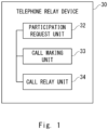
- Fig. 1 is a block diagram illustrating a configuration of a telephone relay device 30 according to a first example embodiment.
- the telephone relay device 30 is a computer device that relays an audio call of a teleconference.
- the telephone relay device 30 is communicably connected to the teleconference server.
- the teleconference server is a computer device that relays an audio call between communication terminals participating in a teleconference via an Internet Protocol (IP) network, via an IP network.
- IP Internet Protocol
- the telephone relay device 30 includes a participation request unit 32, a call making unit 33, and a call relay unit 34.
- the participation request unit 32 requests the teleconference server to permit participation in the teleconference.
- the audio quality reduction notification is a notification indicating that audio quality of the audio call between the communication terminals via the IP network becomes less than a predetermined level.
- the call making unit 33 makes a call to a telephone terminal associated with the communication terminal in response to permission of the telephone relay device 30 to participate in the teleconference. Namely, the call making unit 33 calls the telephone terminal.
- the call relay unit 34 relays the audio call of the teleconference between the telephone terminal and the teleconference server in response to receiving a response to the call from the called telephone terminal.
- the telephone relay device 30 participates in the teleconference, automatically establishes a connection of the audio call by the telephone terminal, and relays the audio call. Therefore, the telephone relay device 30 may avoid hindering the progress of the teleconference and continue the teleconference. On the other hand, since a user only needs to respond to the call, a burden on the user is reduced.
- Fig. 2 is a schematic configuration diagram of a teleconference system 1 to which a telephone relay device according to a second example embodiment can be applied.
- the teleconference system 1 is a computer system that provides a teleconference service to a user of a communication terminal.
- the teleconference system 1 includes a teleconference server 10, a communication terminal 20, an in-house telephone terminal 22, and a private branch exchange (PBX) 30a as an example of the telephone relay device 30.
- PBX private branch exchange
- the teleconference system 1 includes a plurality of communication terminals 20.
- the teleconference system 1 may include a plurality of in-house telephone terminals 22.
- the teleconference server 10 is a computer device such as a server computer that relays data communication between the communication terminals 20 participating in a teleconference.
- the teleconference server 10 is connected to the Internet 2 as an example of an IP network and to a Public Switched Telephone Network (PSTN) as an example of a telephone line.
- PSTN Public Switched Telephone Network
- the teleconference server 10 transmits these data to another communication terminal 20 participating in the teleconference via the Internet 2.
- the teleconference server 10 receives the audio call data from the in-house telephone terminal 22 usable by a user of the communication terminal 20 via a PSTN 3.
- the communication terminal 20 is a personal computer, a notebook computer, a tablet terminal, or other computer devices that can input and output data, which is used by a participant (user) of the teleconference.
- the communication terminal 20 is connected to the Internet 2 via a switching hub 5 and a router 4.
- the communication terminal 20 transmits audio call data generated in response to user's audio being picked up to the teleconference server 10 via the Internet 2, and receives audio call data of another communication terminal 20 participating in the teleconference from the teleconference server 10. Further, the communication terminal 20 transmits other media data such as image data to the teleconference server 10 and receives the other media data from the teleconference server 10 via the Internet 2.
- the in-house telephone terminal 22 is an in-house telephone terminal usable by a user of the communication terminal 20.
- the in-house telephone terminal 22 may be a fixed telephone or a mobile telephone.
- the in-house telephone terminal 22 is a telephone terminal under the control of the so-called PBX 30a, which is connected to the PBX 30a via an in-house line.
- PBX 30a which is connected to the PBX 30a via an in-house line.
- the PBX 30a is a private branch exchange associated with a communication terminal.
- the PBX 30a is connected to the PSTN 3 and the in-house line.
- the PBX 30a is connected to the Internet 2 via the switching hub 5 and the router 4.
- the PBX 30a is configured to participate in the teleconference and call the in-house telephone terminal 22 in response to receiving an audio quality reduction notification from the teleconference server 10.
- the PBX 30a relays an audio call between the teleconference server 10 and the in-house telephone terminal 22.
- the teleconference server 10 receives audio call data from another communication terminal 20 or another in-house telephone terminal 22 participating in the teleconference, and transmits the audio call data to the in-house telephone terminal 22.
- the user of the communication terminal 20 can continue the audio call by using the in-house telephone terminal 22.
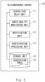
- Fig. 3 is a block diagram illustrating a configuration of the teleconference server 10 according to the second example embodiment.
- the teleconference server 10 includes a server-side relay unit 11, an audio quality monitoring unit 12, a notification unit 13, a participation processing unit 14, and a storage unit 15.
- the server-side relay unit 11 performs processing of relaying an audio call between the communication terminals 20 participating in the teleconference via the Internet 2. Further, the server-side relay unit 11 transmits and receives audio call data of the teleconference to and from the in-house telephone terminal 22 associated with the communication terminal 20 by using the PSTN 3 via the PBX 30a participating in the teleconference. Namely, the server-side relay unit 11 continues to relay the audio call between the communication terminals 20 by using the PSTN 3 or by using the PSTN 3 and the Internet 2.
- the audio quality monitoring unit 12 monitors the audio quality of the audio call between the communication terminals 20 via the Internet 2 for each user participating in the teleconference, i.e., for each communication terminal 20.
- the audio quality monitoring unit 12 may evaluate the audio quality by communication delay, jitter, packet loss, or the like.
- the notification unit 13 transmits an audio quality reduction notification to the PBX 30a via the Internet 2.
- the case where the audio quality becomes less than the predetermined level may be, for example, a case where the communication delay, the jitter, or the packet loss is equal to or greater than a predetermined threshold, or a case where an index determined based on the communication delay, the jitter, and the packet loss is less than a predetermined threshold.
- the audio quality reduction notification includes identification information (ID) of the user of the communication terminal 20 whose audio quality is reduced, an ID and a password of a teleconference in which the user participates.
- the ID of the teleconference may be a dial-in number. This allows the PBX 30a to easily request permission to participate in the teleconference.
- the participation processing unit 14 performs processing of permitting participation in the teleconference in response to receiving a request for permission to participate in the teleconference from the PBX 30a.
- the participation processing unit 14 notifies the PBX 30a of an ID of the in-house telephone terminal 22 associated with a target user in response to the permission of participation to the PBX 30a.
- the storage unit 15 is a storage medium that stores an association table 16 to be described later.
- Fig. 4 is a diagram illustrating an example of a data structure of the association table 16 according to the second example embodiment.
- the association table 16 associates the ID of the communication terminal 20, the ID of the in-house telephone terminal 22, and an ID of the PBX 30a with each other.
- the ID of the communication terminal 20 may be an IP address or a Media Access Control (MAC) address.
- the ID of the in-house telephone terminal 22 may be a telephone number or an extension number.
- the ID of the PBX 30a may be an IP address or a MAC address.
- the association table 16 may associate an ID of the user with the ID of the in-house telephone terminal 22 and the ID of the PBX 30a in place of or in addition to the ID of the communication terminal 20.
- the association table 16 may store the ID and the password of the teleconference in association with the ID of the communication terminal 20.
- the teleconference server 10 can easily and quickly notify the PBX 30a of the communication terminal 20 whose audio quality has reduced, and can also notify the ID of the in-house telephone terminal 22.
- Fig. 5 is a block diagram illustrating a configuration of the PBX 30a according to the second example embodiment.
- the PBX 30a includes an IP communication unit 31, a participation request unit 32, a call making unit 33, and a call relay unit 34.
- the IP communication unit 31 communicates with the teleconference server 10 via the Internet 2. Specifically, the IP communication unit 31 receives the audio quality reduction notification from the teleconference server 10.
- the participation request unit 32 requests the teleconference server 10 to permit participation in the teleconference by using the ID and the password of the teleconference included in the audio quality reduction notification.
- the call making unit 33 makes a call to the in-house telephone terminal 22 through the use of the in-house line, by using the ID of the in-house telephone terminal 22 associated with the communication terminal 20, which is notified in response to being permitted to participate in the teleconference.
- the call relay unit 34 In response to the response from the in-house telephone terminal 22, the call relay unit 34 relays the audio call of the teleconference between the in-house telephone terminal 22 and the teleconference server 10 via the in-house line and the PSTN 3.
- the PBX 30a relays an audio call by using a telephone line different from the Internet 2, it is possible to avoid mixing with other media data and prevent reduction of audio quality.
- call charges can be borne by an organization (company).
- Fig. 6 is a sequence diagram illustrating an example of a processing procedure of the teleconference system 1 according to the second example embodiment.
- a user of the communication terminal 20 participates in a teleconference from a teleconference application of the communication terminal 20, and performs an audio call and other data communication.
- the server-side relay unit 11 of the teleconference server 10 relays the audio call of the communication terminal 20 to the communication terminal 20 to be used by another participant via the Internet 2 (step S 10).
- the audio quality monitoring unit 12 of the teleconference server 10 detects reduction in audio quality (step S11).
- the notification unit 13 of the teleconference server 10 refers to the association table 16 of the storage unit 15, identifies the PBX 30a associated with the ID of the communication terminal 20 to be targeted, and transmits an audio quality reduction notification to the PBX 30a via the Internet 2 (step S13).
- the audio quality reduction notification includes a dial-in number and a password of the teleconference.
- the participation request unit 32 dials the teleconference and requests the teleconference server 10 to permit participation in the teleconference by using the password (step S14).
- the participation processing unit 14 of the teleconference server 10 permits the PBX 30a to participate in the teleconference, and transmits a participation permission notification to the PBX 30a via the PSTN 3 (step S15). As a result, the PBX 30a is in a state of having participated in the teleconference.
- the participation processing unit 14 transmits a participation preparation notification indicating that participation in the teleconference is permitted to the PBX 30a, to the communication terminal 20 (step S16). As a result, the user of the communication terminal 20 can quickly switch to an audio call by the in-house telephone terminal 22.
- the participation processing unit 14 refers to the association table 16 of the storage unit 15, specifies the telephone number of the in-house telephone terminal 22 associated with the ID of the communication terminal 20, and notifies the PBX 30a of the telephone number via the Internet 2 (step S17). This step may be performed in parallel with step S15.
- the call making unit 33 of the PBX 30a makes a call to the in-house telephone terminal 22 via the in-house line by using the telephone number of the in-house telephone terminal 22 (step S18).
- the call making unit 33 may notify the in-house telephone terminal 22 to disconnect the audio call between the communication terminal 20 and the teleconference server 10. As a result, duplication of the audio can be avoided, and the audio call can be switched smoothly.
- the in-house telephone terminal 22 responds to an incoming call by user operation (step S19).
- the call relay unit 34 of the PBX 30a which has received the response, connects a call path between the teleconference server 10 and the in-house telephone terminal 22 (step S20). As a result, the call relay unit 34 starts to relay the audio call between the teleconference server 10 and the in-house telephone terminal 22 via the in-house line and the PSTN 3 (step S21).
- the user disconnects the audio call between the communication terminal 20 and the teleconference server 10 by user operation (step S22). As a result, switching of the audio call is completed, and duplication of the audio is avoided.
- the server-side relay unit of the teleconference server 10 may automatically disconnect the audio call to and from the communication terminal 20 associated with the in-house telephone terminal 22.
- the audio call can be smoothly switched while reducing the burden on the user.
- the participation processing unit 14 of the teleconference server 10 notifies the PBX 30a of the telephone number of the in-house telephone terminal 22 in step S17, the ID of the communication terminal 20 or the ID of the user may be notified instead.
- the PBX 30a which has received the notification, stores, in a storage unit (not illustrated), a table that associates the ID of the communication terminal 20 or the ID of the user with the telephone number of the telephone terminal that can be used by the user, and may identify the telephone number of the telephone terminal that makes a call by using the table.
- the ID of the in-house telephone terminal may be omitted from the association table 16 of the teleconference server 10.
- the teleconference system 1 switches the audio call to a telephone line with stable audio quality when an IP network state in which a communication delay or a loss occurs during the teleconference is established. Therefore, it is possible to avoid hindering the progress of the teleconference and to continue the teleconference.
- the third example embodiment is characterized in that the PBX 30a relays an audio call between the teleconference server 10 and the in-house telephone terminal 22 via the Internet 2 instead of the PSTN 3.
- Fig. 7 is a schematic configuration diagram of a teleconference system 1b according to the third example embodiment.
- the teleconference system 1b is different from the teleconference system 1 in that the PBX 30a is connected to the Internet 2 via a switching hub 6 different from the switching hub 5 and a router 4, instead of the PSTN 3.
- data (audio call data) with the switching hub 6 is preferentially passed by preferential control or the like, or domains of audio call data and data (other media data) with the switching hub 5 are divided and processed. Therefore, it is possible to avoid reduction in audio quality.
- step S14 in Fig. 6 the IP communication unit 31 of the PBX 30a requests the teleconference server 10 to permit participation in the teleconference via the Internet 2.
- the participation processing unit 14 of the teleconference server 10 transmits a participation permission notification to the PBX 30a via the Internet 2.
- the call relay unit 34 relays an audio call between the teleconference server 10 and the in-house telephone terminal 22 via an in-house line and the Internet 2.
- the fourth example embodiment is characterized in telephone relay processing in a case where a user of the communication terminal 20 can use a plurality of telephone terminals of different types.
- Fig. 8 is a schematic configuration diagram of a teleconference system 1c according to the fourth example embodiment.
- the teleconference system 1c has basically the same configuration and function as the teleconference system 1, but is different from the teleconference system 1 in that it includes a mobile telephone terminal 24 and a PBX 30c instead of the PBX 30a.
- the mobile telephone terminal 24 is a telephone terminal that can be used by a user of the communication terminal 20 in addition to the in-house telephone terminal 22.
- the mobile telephone terminal 24 is a mobile telephone, a smartphone, or the like that can be connected to the PSTN 3.
- the user of the communication terminal 20 selects either the in-house telephone terminal 22 or the mobile telephone terminal 24 and continues the audio call.
- the PBX 30c has basically the same configuration and function as the PBX 30a, but is different from the PBX 30a in that the call making unit 33 acquires terminal type information of the telephone terminal selected by the user from the teleconference server and determines a line to be used for the call to the telephone terminal, based on the terminal type information.
- the line to be used for the call is, for example, an external line or an internal line.
- Fig. 9 is a diagram illustrating an example of a data structure of the association table 16 according to the fourth example embodiment.
- the association table 16 according to the fourth example embodiment associates the ID of the communication terminal 20, the ID of the telephone terminal, the terminal type, and the ID of the PBX 30c with each other.
- the terminal type is information indicating the type of the telephone terminal, and is, for example, an in-house telephone or a mobile telephone.
- the ID of the telephone terminal is an ID of the in-house telephone terminal 22 or the mobile telephone terminal 24, and for example, when the terminal type is an in-house telephone, the extension number may be indicated, and when the terminal type is a mobile telephone, the mobile telephone number may be indicated.
- the communication terminal 20 having an ID of "UE002" is associated with two telephone terminals having different terminal types, i.e., the in-house telephone terminal 22 and the mobile telephone terminal 24.
- the ID of the communication terminal 20 may be associated with a plurality of telephone terminals of the same terminal type.
- Fig. 10 is a sequence diagram illustrating an example of a processing procedure of the teleconference system 1c according to the fourth example embodiment.
- the same steps as those in Fig. 6 are denoted by the same symbols, and the description thereof will be omitted.
- the teleconference system 1c executes the processing of steps S10 to S16.
- the participation processing unit 14 of the teleconference server 10 refers to the association table 16 of the storage unit 15, and requests the communication terminal 20 to select a telephone terminal to be used when there are a plurality of telephone terminals associated with the target communication terminal 20 (step S30).
- the communication terminal 20 which has received the selection request, selects a telephone terminal to be used by user operation, and notifies the teleconference server 10 of the selected telephone terminal (step S31).
- the in-house telephone terminal 22 When the in-house telephone terminal 22 is selected, the same processing as in steps S17 to S22 in Fig. 6 may be executed. In this example, it is assumed that the mobile telephone terminal 24 is selected.
- the participation processing unit 14 of the teleconference server 10 refers to the association table 16 of the storage unit 15, acquires information of the selected telephone terminal, and transmits the information of the telephone terminal to the PBX 30c via the Internet 2 (step S32).
- the information of the telephone terminal includes terminal type information of the telephone terminal.
- the information of the telephone terminal includes that the terminal type is a mobile telephone and a mobile telephone number of the mobile telephone terminal 24. This allows the PBX 30c to smoothly determine the line.
- the call making unit 33 of the PBX 30c determines to make a call using an external line, i.e., PSTN 3, from the terminal type information, uses the telephone number of the mobile telephone terminal 24, and makes a call to the mobile telephone terminal 24 by using the PSTN 3 (step S33).
- PSTN 3 an external line
- the mobile telephone terminal 24 responds to the call by user operation (step S34).
- the call relay unit 34 of the PBX 30c which has received the response, connects a call path between the teleconference server 10 and the mobile telephone terminal 24 (step S35). As a result, the call relay unit 34 starts to relay the audio call between the teleconference server 10 and the mobile telephone terminal 24 via the PSTN 3 (step S36).
- Fig. 11 is a diagram illustrating an example of display of the communication terminal 20 according to the fourth example embodiment.
- a display unit (not illustrated) of the communication terminal 20 receives a participation preparation notification and a terminal selection request from the teleconference server 10, and displays a screen as illustrated in the figure.
- a display screen of a teleconference application in which a pop-up display for prompting switching of a terminal to be used for an audio call is displayed is illustrated in the figure.
- the selected telephone terminal is called from the PBX 30c.
- the audio output of the communication terminal 20 may be muted or the audio call may be disconnected in response to the user selecting the telephone terminal of the switching destination.
- the teleconference system 1c can deal with various telephone terminals while achieving the same effects as those of the second example embodiment.
- the call charge can be borne by an organization. For example, even when a user participates in a teleconference at a personal mobile terminal from outside his/her company by telework or the like, the call charge can be borne by the company.
- present disclosure has been explained as a hardware configuration in the above-described example embodiments, the present disclosure is not limited thereto.
- the present disclosure can also achieve various processing related to the telephone relay method by causing a processor to execute a computer program.
- Fig. 12 is a hardware configuration diagram of a computer 900 according to the first to fourth example embodiments.
- the computer 900 includes a processor 100, a Read Only Memory 101 (ROM), a Random Access Memory 102 (RAM), and an Interface unit 103 (IF).
- the processor 100, the ROM 101, the RAM 102, and the interface unit 103 are connected to each other via a data bus or the like.
- the processor 100 has a function as an arithmetic device that performs control processing, arithmetic processing, and the like.
- the processor 100 may be a Central Processing Unit (CPU), a Graphics Processing Unit (GPU), a field-programmable gate array (FPGA), a digital signal processor (DSP), or an application specific integrated circuit (ASIC), and combinations thereof.
- the ROM 101 has a function for storing a control program, an arithmetic program, and the like that are executed by the processor 100.
- the RAM 102 has a function for temporarily storing processing data and the like.
- the interface unit 103 inputs and outputs a signal to and from the outside via a wire or wirelessly.
- the interface unit 103 receives an operation of inputting data by the user, and displays information to the user.
- the interface unit 103 of the teleconference server 10 communicates with the interface unit 103 of the communication terminal 20 and the interface unit 103 of the PBX 30a.
- the program when loaded into a computer, includes an instruction group (or software code) to cause a computer to perform one or more of the functions described in the example embodiments.
- the program may be stored in a non-transitory computer-readable medium or a tangible storage medium.
- computer-readable media or tangible storage media include random-access memory (RAM), read-only memory (ROM), flash memory, solid-state drive (SSD) or other memory techniques, CD-ROM, digital versatile disc (DVD), Blu-ray (registered trademark) disk or other optical disk storage, magnetic cassettes, magnetic tape, magnetic disk storage, or other magnetic storage devices.
- the program may be transmitted on a transitory computer readable medium or a communication medium.
- transitory computer-readable media or communication media include electrical, optical, acoustic, or other forms of propagated signals.
- the computer 900 includes a computer system including a personal computer, a word processor, and the like.
- the present invention is not limited thereto, and the computer may be constituted by a server of a local area network (LAN), a host of computer (personal computer) communication, a computer system connected to the Internet, or the like.
- LAN local area network
- personal computer personal computer
- a telephone relay device being communicably connected to a teleconference server configured to relay an audio call between communication terminals participating in a teleconference via an Internet Protocol (IP) network, the telephone relay device including:
- the telephone relay device according to Supplementary note 1, wherein the call relay unit relays the audio call between the telephone terminal and the teleconference server via a telephone line.
- the telephone relay device according to Supplementary note 1 or 2, wherein the telephone relay device is a private branch exchange associated with the communication terminal.
- the telephone relay device according to any one of Supplementary notes 1 to 3, wherein the call making unit acquires terminal type information of the telephone terminal from the teleconference server, and determines a line to be used for the call to the telephone terminal, based on the terminal type information.
- the telephone relay device according to any one of Supplementary notes 1 to 4, wherein the call making unit requests the telephone terminal to disconnect the audio call between the communication terminal and the teleconference server.
- a teleconference server including:
- the teleconference server according to Supplementary note 6, wherein the server-side relay unit disconnects the audio call with the communication terminal associated with the telephone terminal when the server-side relay unit starts transmitting and receiving the audio call data with the telephone terminal.
- the teleconference server according to Supplementary note 6 or 7, wherein the participation processing unit transmits, to the communication terminal, a participation preparation notification indicating that participation in the teleconference is permitted to the telephone relay device.
- the teleconference server wherein, when there are a plurality of telephone terminals associated with the communication terminal, the participation processing unit requests the communication terminal to select a telephone terminal to be used, and transmits information of the selected telephone terminal to the telephone relay device.
- the teleconference server according to Supplementary note 9, wherein the information of the telephone terminal includes terminal type information of the telephone terminal.
- the teleconference server according to any one of Supplementary notes 6 to 10, further including an audio quality monitoring unit configured to monitor audio quality of the audio call between the communication terminals.
- a teleconference system including:
- a telephone relay method for a telephone relay device being communicably connected to a teleconference server configured to relay an audio call between communication terminals participating in a teleconference via an Internet Protocol (IP) network
- IP Internet Protocol
- the telephone relay method further including relaying the audio call between the telephone terminal and the teleconference server via a telephone line.
- the telephone relay method according to any one of Supplementary notes 13 to 15, further including requesting the telephone terminal to disconnect the audio call between the communication terminal and the teleconference server.
- An audio call relay method for a teleconference server configured to relay an audio call between communication terminals participating in a teleconference via an Internet Protocol (IP) network
- the audio call relay method including:
- the audio call relay method further including disconnecting the audio call with the communication terminal associated with the telephone terminal when audio call data are started to be transmitted and received to and from the telephone terminal.
- the audio call relay method according to Supplementary note 18 or 19, further including transmitting, to the communication terminal, a participation preparation notification indicating that participation in the teleconference is permitted to the telephone relay device.
- the audio call relay method further including: when there are a plurality of telephone terminals associated with the communication terminal, requesting the communication terminal to select a telephone terminal to be used; and transmitting information of the selected telephone terminal to the telephone relay device.
- the telephone relay device, the teleconference server, and the teleconference system according to the present example embodiments can be used, for example, in order to relay an audio call of a teleconference.
Landscapes
- Engineering & Computer Science (AREA)
- Multimedia (AREA)
- Signal Processing (AREA)
- Computer Vision & Pattern Recognition (AREA)
- General Engineering & Computer Science (AREA)
- Telephonic Communication Services (AREA)
- Data Exchanges In Wide-Area Networks (AREA)
Abstract
Description
- The present disclosure relates to a telephone relay device, a teleconference server, a teleconference system, a telephone relay method, an audio call relay method, and a program.
- In a teleconference system to be operated on the web, data communication delays and missing may occur depending on communication conditions of Internet Protocol (IP) networks. In this case, a trouble may occur in an audio call, and progress of a teleconference may be hindered. In order to avoid such a situation, it has been proposed to participate in a teleconference from a telephone terminal.
- However, in order to participate in a teleconference from a telephone terminal, a procedure such as a speaker dialing a telephone number of the teleconference from the telephone terminal and inputting a password of the teleconference is required. Further, since the speaker often does not notice that audio quality is reduced, the above-described procedure is performed while waiting for another conference participant who notices interruption or delay of the audio to communicate to the speaker. Therefore, there is a problem that the conference is interrupted in the meantime.
- Therefore,
Patent Literature 1 discloses that an information processing apparatus monitors communication environment and causes a server apparatus to change signal transmission conditions of video and audio according to the communication environment, by focusing on processing of the information processing apparatus to be used by participants in a conference. - [Patent Literature 1]
Japanese Unexamined Patent Application Publication No. 2017-151889 - However, in the information processing apparatus described in
Patent Literature 1 described above, since audio data having a low audio quality level is received when a communication state is reduced, there is a possibility that progress of a teleconference is hindered by that. - In view of the above-described problem, an object of the present disclosure is to provide a telephone relay device, a teleconference server, a teleconference system, a telephone relay method, an audio call relay method, and a program that are able to avoid hindrance to progress of the teleconference.
- A telephone relay device according to an aspect of the present disclosure is communicably connected to a teleconference server that relays an audio call between communication terminals participating in a teleconference via an Internet Protocol (IP) network. The telephone relay device includes a participation request unit, a call making unit, and a call relay unit. The participation request unit requests the teleconference server to permit participation in the teleconference in response to receiving an audio quality reduction notification indicating that audio quality of the audio call between the communication terminals becomes less than a predetermined level, from the teleconference server. The call making unit makes a call to a telephone terminal associated with the communication terminal in response to being permitted to participate in the teleconference. In response to receiving a response to the call from the telephone terminal, the call relay unit relays an audio call of the teleconference between the telephone terminal and the teleconference server.
- A teleconference server according to an aspect of the present disclosure includes a server-side relay unit, a notification unit, and a participation processing unit. The server-side relay unit relays an audio call between communication terminals participating in a teleconference via an IP network. The notification unit transmits an audio quality reduction notification to a telephone relay device when audio quality of the audio call between the communication terminals becomes less than a predetermined level. The participation processing unit permits participation in the teleconference in response to receiving a request for permission to participate in the teleconference from the telephone relay device. The server-side relay unit transmits and receives audio call data of the teleconference to and from a telephone terminal associated with the communication terminal via the telephone relay device participating in the teleconference.
- A teleconference system according to an aspect of the present disclosure includes the above-described telephone relay device and the above-described teleconference server.
- A telephone relay method according to an aspect of the present disclosure is a telephone relay method for a telephone relay device communicably connected to a teleconference server that relays an audio call between communication terminals participating in a teleconference via an IP network. The telephone relay method includes: requesting the teleconference server to permit participation in the teleconference in response to receiving an audio quality reduction notification indicating that audio quality of the audio call between the communication terminals becomes less than a predetermined level, from the teleconference server; making a call to a telephone terminal associated with the communication terminal in response to being permitted to participate in the teleconference; and relaying an audio call of the teleconference between the telephone terminal and the teleconference server in response to receiving a response to the call from the telephone terminal.
- A program according to an aspect of the present disclosure is a program for causing a computer to execute the above-described telephone relay method.
- An audio call relay method according to an aspect of the present disclosure is an audio call relay method for a teleconference server that relays an audio call between communication terminals participating in a teleconference via an IP network. The audio call relay method includes: transmitting an audio quality reduction notification to a telephone relay device when audio quality of the audio call between the communication terminals becomes less than a predetermined level; permitting participation in the teleconference in response to receiving a request for permission to participate in the teleconference from the telephone relay device; and transmitting and receiving audio call data of the teleconference to and from a telephone terminal associated with the communication terminal via the telephone relay device participating in the teleconference.
- A program according to an aspect of the present disclosure is a program for causing a computer to execute the above-described audio call relay method.
- According to the present disclosure, it is possible to provide a telephone relay device, a teleconference server, a teleconference system, a telephone relay method, an audio call relay method, and a program that are capable of avoiding hindrance to progress of a teleconference because a telephone relay device participates in a teleconference and relays an audio call by a telephone terminal in a case where audio quality is reduced.
-
-
Fig. 1 is a block diagram illustrating a configuration of a telephone relay device according to a first example embodiment; -
Fig. 2 is a schematic configuration diagram of a teleconference system to which the telephone relay device according to a second example embodiment can be applied; -
Fig. 3 is a block diagram illustrating a configuration of a teleconference server according to the second example embodiment; -
Fig. 4 is a diagram illustrating an example of a data structure of an association table according to the second example embodiment; -
Fig. 5 is a block diagram illustrating a configuration of a PBX according to the second example embodiment; -
Fig. 6 is a sequence diagram illustrating an example of a processing procedure of a teleconference system according to the second example embodiment; -
Fig. 7 is a schematic configuration diagram of a teleconference system according to a third example embodiment; -
Fig. 8 is a schematic configuration diagram of a teleconference system according to a fourth example embodiment; -
Fig. 9 is a diagram illustrating an example of a data structure of an association table according to the fourth example embodiment; -
Fig. 10 is a sequence diagram illustrating an example of a processing procedure of the teleconference system according to the fourth example embodiment; -
Fig. 11 is a diagram illustrating an example of a display of a communication terminal according to the fourth example embodiment; and -
Fig. 12 is a hardware configuration diagram of a computer according to the first to fourth example embodiments. - Hereinafter, the present disclosure will be described through example embodiments, but the invention according to claims is not limited to the following example embodiments. Further, not all of configurations to be described in the example embodiments are essential as a means for solving the problem. For clarity of explanation, the following description and the drawings are omitted and simplified as appropriate. In the drawings, the same elements are denoted by the same reference numerals.
- First, a first example embodiment of the present disclosure will be described by using
Fig. 1. Fig. 1 is a block diagram illustrating a configuration of atelephone relay device 30 according to a first example embodiment. Thetelephone relay device 30 is a computer device that relays an audio call of a teleconference. Thetelephone relay device 30 is communicably connected to the teleconference server. Herein, the teleconference server is a computer device that relays an audio call between communication terminals participating in a teleconference via an Internet Protocol (IP) network, via an IP network. - The
telephone relay device 30 includes aparticipation request unit 32, acall making unit 33, and acall relay unit 34. - In response to receiving an audio quality reduction notification from the teleconference server, the
participation request unit 32 requests the teleconference server to permit participation in the teleconference. The audio quality reduction notification is a notification indicating that audio quality of the audio call between the communication terminals via the IP network becomes less than a predetermined level. - The
call making unit 33 makes a call to a telephone terminal associated with the communication terminal in response to permission of thetelephone relay device 30 to participate in the teleconference. Namely, thecall making unit 33 calls the telephone terminal. - The
call relay unit 34 relays the audio call of the teleconference between the telephone terminal and the teleconference server in response to receiving a response to the call from the called telephone terminal. - As described above, according to the first example embodiment, in a case where an IP network state occurs in which a communication delay or a loss occurs during a teleconference, the
telephone relay device 30 participates in the teleconference, automatically establishes a connection of the audio call by the telephone terminal, and relays the audio call. Therefore, thetelephone relay device 30 may avoid hindering the progress of the teleconference and continue the teleconference. On the other hand, since a user only needs to respond to the call, a burden on the user is reduced. - Next, a second example embodiment of the present disclosure will be described by using
Figs. 2 to 6 . -
Fig. 2 is a schematic configuration diagram of ateleconference system 1 to which a telephone relay device according to a second example embodiment can be applied. Theteleconference system 1 is a computer system that provides a teleconference service to a user of a communication terminal. Theteleconference system 1 includes ateleconference server 10, acommunication terminal 20, an in-house telephone terminal 22, and a private branch exchange (PBX) 30a as an example of thetelephone relay device 30. Although onecommunication terminal 20 is illustrated in this figure for clarity of explanation, it is assumed that theteleconference system 1 includes a plurality ofcommunication terminals 20. In addition, although one in-house telephone terminal 22 is illustrated in the figure, theteleconference system 1 may include a plurality of in-house telephone terminals 22. - The
teleconference server 10 is a computer device such as a server computer that relays data communication between thecommunication terminals 20 participating in a teleconference. Theteleconference server 10 is connected to the Internet 2 as an example of an IP network and to a Public Switched Telephone Network (PSTN) as an example of a telephone line. In response to receiving audio data (audio call data) of thecommunication terminal 20 and other media data via the Internet 2, theteleconference server 10 transmits these data to anothercommunication terminal 20 participating in the teleconference via the Internet 2. - When audio quality of the audio call becomes less than a predetermined level, the
teleconference server 10 receives the audio call data from the in-house telephone terminal 22 usable by a user of thecommunication terminal 20 via aPSTN 3. - The
communication terminal 20 is a personal computer, a notebook computer, a tablet terminal, or other computer devices that can input and output data, which is used by a participant (user) of the teleconference. In this figure, thecommunication terminal 20 is connected to the Internet 2 via a switching hub 5 and a router 4. Thecommunication terminal 20 transmits audio call data generated in response to user's audio being picked up to theteleconference server 10 via the Internet 2, and receives audio call data of anothercommunication terminal 20 participating in the teleconference from theteleconference server 10. Further, thecommunication terminal 20 transmits other media data such as image data to theteleconference server 10 and receives the other media data from theteleconference server 10 via the Internet 2. - Therefore, in the network, traffic of audio call data and other media data is mixed, and thus, there is a problem that the audio quality of audio call is likely to be reduced.
- The in-
house telephone terminal 22 is an in-house telephone terminal usable by a user of thecommunication terminal 20. The in-house telephone terminal 22 may be a fixed telephone or a mobile telephone. The in-house telephone terminal 22 is a telephone terminal under the control of the so-calledPBX 30a, which is connected to thePBX 30a via an in-house line. When audio quality of an audio call by thecommunication terminal 20 is reduced, the user of thecommunication terminal 20 continues the audio call by using the in-house telephone terminal 22. - The
PBX 30a is a private branch exchange associated with a communication terminal. ThePBX 30a is connected to thePSTN 3 and the in-house line. ThePBX 30a is connected to the Internet 2 via the switching hub 5 and the router 4. ThePBX 30a is configured to participate in the teleconference and call the in-house telephone terminal 22 in response to receiving an audio quality reduction notification from theteleconference server 10. ThePBX 30a relays an audio call between theteleconference server 10 and the in-house telephone terminal 22. - As a result, the
teleconference server 10 receives audio call data from anothercommunication terminal 20 or another in-house telephone terminal 22 participating in the teleconference, and transmits the audio call data to the in-house telephone terminal 22. Thus, even when the audio quality of the audio call by thecommunication terminal 20 becomes low, the user of thecommunication terminal 20 can continue the audio call by using the in-house telephone terminal 22. -
Fig. 3 is a block diagram illustrating a configuration of theteleconference server 10 according to the second example embodiment. Theteleconference server 10 includes a server-side relay unit 11, an audioquality monitoring unit 12, anotification unit 13, aparticipation processing unit 14, and astorage unit 15. - The server-
side relay unit 11 performs processing of relaying an audio call between thecommunication terminals 20 participating in the teleconference via the Internet 2. Further, the server-side relay unit 11 transmits and receives audio call data of the teleconference to and from the in-house telephone terminal 22 associated with thecommunication terminal 20 by using thePSTN 3 via thePBX 30a participating in the teleconference. Namely, the server-side relay unit 11 continues to relay the audio call between thecommunication terminals 20 by using thePSTN 3 or by using thePSTN 3 and the Internet 2. - The audio
quality monitoring unit 12 monitors the audio quality of the audio call between thecommunication terminals 20 via the Internet 2 for each user participating in the teleconference, i.e., for eachcommunication terminal 20. The audioquality monitoring unit 12 may evaluate the audio quality by communication delay, jitter, packet loss, or the like. - When the audio quality evaluated by the audio
quality monitoring unit 12 becomes less than a predetermined level, thenotification unit 13 transmits an audio quality reduction notification to thePBX 30a via the Internet 2. The case where the audio quality becomes less than the predetermined level may be, for example, a case where the communication delay, the jitter, or the packet loss is equal to or greater than a predetermined threshold, or a case where an index determined based on the communication delay, the jitter, and the packet loss is less than a predetermined threshold. The audio quality reduction notification includes identification information (ID) of the user of thecommunication terminal 20 whose audio quality is reduced, an ID and a password of a teleconference in which the user participates. The ID of the teleconference may be a dial-in number. This allows thePBX 30a to easily request permission to participate in the teleconference. - The
participation processing unit 14 performs processing of permitting participation in the teleconference in response to receiving a request for permission to participate in the teleconference from thePBX 30a. Theparticipation processing unit 14 notifies thePBX 30a of an ID of the in-house telephone terminal 22 associated with a target user in response to the permission of participation to thePBX 30a. - The
storage unit 15 is a storage medium that stores an association table 16 to be described later. -
Fig. 4 is a diagram illustrating an example of a data structure of the association table 16 according to the second example embodiment. The association table 16 associates the ID of thecommunication terminal 20, the ID of the in-house telephone terminal 22, and an ID of thePBX 30a with each other. - The ID of the
communication terminal 20 may be an IP address or a Media Access Control (MAC) address. The ID of the in-house telephone terminal 22 may be a telephone number or an extension number. The ID of thePBX 30a may be an IP address or a MAC address. - The association table 16 may associate an ID of the user with the ID of the in-
house telephone terminal 22 and the ID of thePBX 30a in place of or in addition to the ID of thecommunication terminal 20. In addition, the association table 16 may store the ID and the password of the teleconference in association with the ID of thecommunication terminal 20. - By using the association table 16, the
teleconference server 10 can easily and quickly notify thePBX 30a of thecommunication terminal 20 whose audio quality has reduced, and can also notify the ID of the in-house telephone terminal 22. -
Fig. 5 is a block diagram illustrating a configuration of thePBX 30a according to the second example embodiment. ThePBX 30a includes anIP communication unit 31, aparticipation request unit 32, acall making unit 33, and acall relay unit 34. - The
IP communication unit 31 communicates with theteleconference server 10 via the Internet 2. Specifically, theIP communication unit 31 receives the audio quality reduction notification from theteleconference server 10. - The
participation request unit 32 requests theteleconference server 10 to permit participation in the teleconference by using the ID and the password of the teleconference included in the audio quality reduction notification. - The
call making unit 33 makes a call to the in-house telephone terminal 22 through the use of the in-house line, by using the ID of the in-house telephone terminal 22 associated with thecommunication terminal 20, which is notified in response to being permitted to participate in the teleconference. - In response to the response from the in-
house telephone terminal 22, thecall relay unit 34 relays the audio call of the teleconference between the in-house telephone terminal 22 and theteleconference server 10 via the in-house line and thePSTN 3. - As described above, since the
PBX 30a relays an audio call by using a telephone line different from the Internet 2, it is possible to avoid mixing with other media data and prevent reduction of audio quality. In addition, since the user continues the audio call via thePBX 30a, call charges can be borne by an organization (company). -
Fig. 6 is a sequence diagram illustrating an example of a processing procedure of theteleconference system 1 according to the second example embodiment. - First, a user of the
communication terminal 20 participates in a teleconference from a teleconference application of thecommunication terminal 20, and performs an audio call and other data communication. At this time, the server-side relay unit 11 of theteleconference server 10 relays the audio call of thecommunication terminal 20 to thecommunication terminal 20 to be used by another participant via the Internet 2 (step S 10). Then, it is assumed that the audioquality monitoring unit 12 of theteleconference server 10 detects reduction in audio quality (step S11). Thenotification unit 13 of theteleconference server 10 refers to the association table 16 of thestorage unit 15, identifies thePBX 30a associated with the ID of thecommunication terminal 20 to be targeted, and transmits an audio quality reduction notification to thePBX 30a via the Internet 2 (step S13). The audio quality reduction notification includes a dial-in number and a password of the teleconference. - In response to receiving the audio quality reduction notification by the
IP communication unit 31 of thePBX 30a, theparticipation request unit 32 dials the teleconference and requests theteleconference server 10 to permit participation in the teleconference by using the password (step S14). - The
participation processing unit 14 of theteleconference server 10 permits thePBX 30a to participate in the teleconference, and transmits a participation permission notification to thePBX 30a via the PSTN 3 (step S15). As a result, thePBX 30a is in a state of having participated in the teleconference. Theparticipation processing unit 14 transmits a participation preparation notification indicating that participation in the teleconference is permitted to thePBX 30a, to the communication terminal 20 (step S16). As a result, the user of thecommunication terminal 20 can quickly switch to an audio call by the in-house telephone terminal 22. Further, theparticipation processing unit 14 refers to the association table 16 of thestorage unit 15, specifies the telephone number of the in-house telephone terminal 22 associated with the ID of thecommunication terminal 20, and notifies thePBX 30a of the telephone number via the Internet 2 (step S17). This step may be performed in parallel with step S15. - Then, the
call making unit 33 of thePBX 30a makes a call to the in-house telephone terminal 22 via the in-house line by using the telephone number of the in-house telephone terminal 22 (step S18). At this time, thecall making unit 33 may notify the in-house telephone terminal 22 to disconnect the audio call between thecommunication terminal 20 and theteleconference server 10. As a result, duplication of the audio can be avoided, and the audio call can be switched smoothly. - The in-
house telephone terminal 22 responds to an incoming call by user operation (step S19). - The
call relay unit 34 of thePBX 30a, which has received the response, connects a call path between theteleconference server 10 and the in-house telephone terminal 22 (step S20). As a result, thecall relay unit 34 starts to relay the audio call between theteleconference server 10 and the in-house telephone terminal 22 via the in-house line and the PSTN 3 (step S21). - On the other hand, in response to the response to the incoming call, the user disconnects the audio call between the
communication terminal 20 and theteleconference server 10 by user operation (step S22). As a result, switching of the audio call is completed, and duplication of the audio is avoided. - In a case where the server-side relay unit of the
teleconference server 10 starts to transmit and receive audio call data to and from the in-house telephone terminal 22, the server-side relay unit may automatically disconnect the audio call to and from thecommunication terminal 20 associated with the in-house telephone terminal 22. As a result, the audio call can be smoothly switched while reducing the burden on the user. - In addition, although the
participation processing unit 14 of theteleconference server 10 notifies thePBX 30a of the telephone number of the in-house telephone terminal 22 in step S17, the ID of thecommunication terminal 20 or the ID of the user may be notified instead. ThePBX 30a, which has received the notification, stores, in a storage unit (not illustrated), a table that associates the ID of thecommunication terminal 20 or the ID of the user with the telephone number of the telephone terminal that can be used by the user, and may identify the telephone number of the telephone terminal that makes a call by using the table. In this case, the ID of the in-house telephone terminal may be omitted from the association table 16 of theteleconference server 10. - As described above, according to the second example embodiment, the
teleconference system 1 switches the audio call to a telephone line with stable audio quality when an IP network state in which a communication delay or a loss occurs during the teleconference is established. Therefore, it is possible to avoid hindering the progress of the teleconference and to continue the teleconference. - Next, a third example embodiment of the present disclosure will be described by using
Fig. 7 . The third example embodiment is characterized in that thePBX 30a relays an audio call between theteleconference server 10 and the in-house telephone terminal 22 via the Internet 2 instead of thePSTN 3. -
Fig. 7 is a schematic configuration diagram of ateleconference system 1b according to the third example embodiment. Theteleconference system 1b is different from theteleconference system 1 in that thePBX 30a is connected to the Internet 2 via aswitching hub 6 different from the switching hub 5 and a router 4, instead of thePSTN 3. In the router 4, data (audio call data) with theswitching hub 6 is preferentially passed by preferential control or the like, or domains of audio call data and data (other media data) with the switching hub 5 are divided and processed. Therefore, it is possible to avoid reduction in audio quality. - Therefore, instead of step S14 in
Fig. 6 , theIP communication unit 31 of thePBX 30a requests theteleconference server 10 to permit participation in the teleconference via the Internet 2. Instead of step S15 inFig. 6 , theparticipation processing unit 14 of theteleconference server 10 transmits a participation permission notification to thePBX 30a via the Internet 2. Instead of step S21 inFig. 6 , thecall relay unit 34 relays an audio call between theteleconference server 10 and the in-house telephone terminal 22 via an in-house line and the Internet 2. - As described above, also in the third example embodiment, the same effects as those of the second example embodiment are acquired.
- Next, a fourth example embodiment of the present disclosure will be explained by using
Figs. 8 to 11 . The fourth example embodiment is characterized in telephone relay processing in a case where a user of thecommunication terminal 20 can use a plurality of telephone terminals of different types. -
Fig. 8 is a schematic configuration diagram of ateleconference system 1c according to the fourth example embodiment. Theteleconference system 1c has basically the same configuration and function as theteleconference system 1, but is different from theteleconference system 1 in that it includes amobile telephone terminal 24 and aPBX 30c instead of thePBX 30a. - The
mobile telephone terminal 24 is a telephone terminal that can be used by a user of thecommunication terminal 20 in addition to the in-house telephone terminal 22. Themobile telephone terminal 24 is a mobile telephone, a smartphone, or the like that can be connected to thePSTN 3. When the audio quality of the audio call by thecommunication terminal 20 is reduced, the user of thecommunication terminal 20 selects either the in-house telephone terminal 22 or themobile telephone terminal 24 and continues the audio call. - The
PBX 30c has basically the same configuration and function as thePBX 30a, but is different from thePBX 30a in that thecall making unit 33 acquires terminal type information of the telephone terminal selected by the user from the teleconference server and determines a line to be used for the call to the telephone terminal, based on the terminal type information. The line to be used for the call is, for example, an external line or an internal line. -
Fig. 9 is a diagram illustrating an example of a data structure of the association table 16 according to the fourth example embodiment. The association table 16 according to the fourth example embodiment associates the ID of thecommunication terminal 20, the ID of the telephone terminal, the terminal type, and the ID of thePBX 30c with each other. The terminal type is information indicating the type of the telephone terminal, and is, for example, an in-house telephone or a mobile telephone. The ID of the telephone terminal is an ID of the in-house telephone terminal 22 or themobile telephone terminal 24, and for example, when the terminal type is an in-house telephone, the extension number may be indicated, and when the terminal type is a mobile telephone, the mobile telephone number may be indicated. In this figure, thecommunication terminal 20 having an ID of "UE002" is associated with two telephone terminals having different terminal types, i.e., the in-house telephone terminal 22 and themobile telephone terminal 24. The ID of thecommunication terminal 20 may be associated with a plurality of telephone terminals of the same terminal type. -
Fig. 10 is a sequence diagram illustrating an example of a processing procedure of theteleconference system 1c according to the fourth example embodiment. The same steps as those inFig. 6 are denoted by the same symbols, and the description thereof will be omitted. - First, the
teleconference system 1c executes the processing of steps S10 to S16. - Then, the
participation processing unit 14 of theteleconference server 10 refers to the association table 16 of thestorage unit 15, and requests thecommunication terminal 20 to select a telephone terminal to be used when there are a plurality of telephone terminals associated with the target communication terminal 20 (step S30). - The
communication terminal 20, which has received the selection request, selects a telephone terminal to be used by user operation, and notifies theteleconference server 10 of the selected telephone terminal (step S31). When the in-house telephone terminal 22 is selected, the same processing as in steps S17 to S22 inFig. 6 may be executed. In this example, it is assumed that themobile telephone terminal 24 is selected. - The
participation processing unit 14 of theteleconference server 10 refers to the association table 16 of thestorage unit 15, acquires information of the selected telephone terminal, and transmits the information of the telephone terminal to thePBX 30c via the Internet 2 (step S32). The information of the telephone terminal includes terminal type information of the telephone terminal. In the present example, the information of the telephone terminal includes that the terminal type is a mobile telephone and a mobile telephone number of themobile telephone terminal 24. This allows thePBX 30c to smoothly determine the line. - Then, the
call making unit 33 of thePBX 30c determines to make a call using an external line, i.e.,PSTN 3, from the terminal type information, uses the telephone number of themobile telephone terminal 24, and makes a call to themobile telephone terminal 24 by using the PSTN 3 (step S33). - The
mobile telephone terminal 24 responds to the call by user operation (step S34). - The
call relay unit 34 of thePBX 30c, which has received the response, connects a call path between theteleconference server 10 and the mobile telephone terminal 24 (step S35). As a result, thecall relay unit 34 starts to relay the audio call between theteleconference server 10 and themobile telephone terminal 24 via the PSTN 3 (step S36). -
Fig. 11 is a diagram illustrating an example of display of thecommunication terminal 20 according to the fourth example embodiment. A display unit (not illustrated) of thecommunication terminal 20 receives a participation preparation notification and a terminal selection request from theteleconference server 10, and displays a screen as illustrated in the figure. - For example, a display screen of a teleconference application (Web conference application) in which a pop-up display for prompting switching of a terminal to be used for an audio call is displayed is illustrated in the figure. When the user selects a telephone terminal of a switching destination among the displayed telephone terminals, the selected telephone terminal is called from the
PBX 30c. Note that the audio output of thecommunication terminal 20 may be muted or the audio call may be disconnected in response to the user selecting the telephone terminal of the switching destination. - As described above, according to the fourth example embodiment, the
teleconference system 1c can deal with various telephone terminals while achieving the same effects as those of the second example embodiment. In addition, since the user continues the audio call via thePBX 30c, even when an external line is used, the call charge can be borne by an organization. For example, even when a user participates in a teleconference at a personal mobile terminal from outside his/her company by telework or the like, the call charge can be borne by the company. - Note that the present disclosure is not limited to the above-described example embodiments, and can be appropriately modified without departing from the spirit thereof.
- Although the present disclosure has been explained as a hardware configuration in the above-described example embodiments, the present disclosure is not limited thereto. The present disclosure can also achieve various processing related to the telephone relay method by causing a processor to execute a computer program.
-
Fig. 12 is a hardware configuration diagram of acomputer 900 according to the first to fourth example embodiments. - The
computer 900 includes aprocessor 100, a Read Only Memory 101 (ROM), a Random Access Memory 102 (RAM), and an Interface unit 103 (IF). Theprocessor 100, theROM 101, theRAM 102, and theinterface unit 103 are connected to each other via a data bus or the like. - The
processor 100 has a function as an arithmetic device that performs control processing, arithmetic processing, and the like. Theprocessor 100 may be a Central Processing Unit (CPU), a Graphics Processing Unit (GPU), a field-programmable gate array (FPGA), a digital signal processor (DSP), or an application specific integrated circuit (ASIC), and combinations thereof. TheROM 101 has a function for storing a control program, an arithmetic program, and the like that are executed by theprocessor 100. TheRAM 102 has a function for temporarily storing processing data and the like. Theinterface unit 103 inputs and outputs a signal to and from the outside via a wire or wirelessly. In addition, theinterface unit 103 receives an operation of inputting data by the user, and displays information to the user. For example, theinterface unit 103 of theteleconference server 10 communicates with theinterface unit 103 of thecommunication terminal 20 and theinterface unit 103 of thePBX 30a. - In the examples described above, the program, when loaded into a computer, includes an instruction group (or software code) to cause a computer to perform one or more of the functions described in the example embodiments. The program may be stored in a non-transitory computer-readable medium or a tangible storage medium. By way of example, and not limitation, computer-readable media or tangible storage media include random-access memory (RAM), read-only memory (ROM), flash memory, solid-state drive (SSD) or other memory techniques, CD-ROM, digital versatile disc (DVD), Blu-ray (registered trademark) disk or other optical disk storage, magnetic cassettes, magnetic tape, magnetic disk storage, or other magnetic storage devices. The program may be transmitted on a transitory computer readable medium or a communication medium. By way of example, and not limitation, transitory computer-readable media or communication media include electrical, optical, acoustic, or other forms of propagated signals.
- In the above-described example embodiments, the
computer 900 includes a computer system including a personal computer, a word processor, and the like. However, the present invention is not limited thereto, and the computer may be constituted by a server of a local area network (LAN), a host of computer (personal computer) communication, a computer system connected to the Internet, or the like. In addition, it is also possible to distribute functions among devices on a network and configure a computer over the entire network. - Some or all of the above-described example embodiments may be described as the following supplementary notes, but are not limited thereto.
- A telephone relay device being communicably connected to a teleconference server configured to relay an audio call between communication terminals participating in a teleconference via an Internet Protocol (IP) network, the telephone relay device including:
- a participation request unit configured to request the teleconference server to permit participation in the teleconference in response to receiving an audio quality reduction notification indicating that audio quality of the audio call between the communication terminals becomes less than a predetermined level, from the teleconference server;
- a call making unit configured to make a call to a telephone terminal associated with the communication terminal in response to being permitted to participate in the teleconference; and
- a call relay unit configured to relay an audio call of the teleconference between the telephone terminal and the teleconference server in response to receiving a response to the call from the telephone terminal.
- The telephone relay device according to
Supplementary note 1, wherein the call relay unit relays the audio call between the telephone terminal and the teleconference server via a telephone line. - The telephone relay device according to
Supplementary note 1 or 2, wherein the telephone relay device is a private branch exchange associated with the communication terminal. - The telephone relay device according to any one of
Supplementary notes 1 to 3, wherein the call making unit acquires terminal type information of the telephone terminal from the teleconference server, and determines a line to be used for the call to the telephone terminal, based on the terminal type information. - The telephone relay device according to any one of
Supplementary notes 1 to 4, wherein the call making unit requests the telephone terminal to disconnect the audio call between the communication terminal and the teleconference server. - A teleconference server including:
- a server-side relay unit configured to relay an audio call between communication terminals participating in a teleconference via an Internet Protocol (IP) network;
- a notification unit configured to transmit an audio quality reduction notification to a telephone relay device when audio quality of the audio call between the communication terminals becomes less than a predetermined level; and
- a participation processing unit configured to permit participation in the teleconference in response to receiving a request for permission to participate in the teleconference from the telephone relay device,
- wherein the server-side relay unit transmits and receives audio call data of the teleconference to and from a telephone terminal associated with the communication terminal via the telephone relay device participating in the teleconference.
- The teleconference server according to
Supplementary note 6, wherein the server-side relay unit disconnects the audio call with the communication terminal associated with the telephone terminal when the server-side relay unit starts transmitting and receiving the audio call data with the telephone terminal. - The teleconference server according to
Supplementary note 6 or 7, wherein the participation processing unit transmits, to the communication terminal, a participation preparation notification indicating that participation in the teleconference is permitted to the telephone relay device. - The teleconference server according to Supplementary note 8, wherein, when there are a plurality of telephone terminals associated with the communication terminal, the participation processing unit requests the communication terminal to select a telephone terminal to be used, and transmits information of the selected telephone terminal to the telephone relay device.
- The teleconference server according to Supplementary note 9, wherein the information of the telephone terminal includes terminal type information of the telephone terminal.
- The teleconference server according to any one of
Supplementary notes 6 to 10, further including an audio quality monitoring unit configured to monitor audio quality of the audio call between the communication terminals. - A teleconference system including:
- the telephone relay device according to any one of
Supplementary notes 1 to 5; and - the teleconference server according to any one of
Supplementary notes 6 to 11. - A telephone relay method for a telephone relay device being communicably connected to a teleconference server configured to relay an audio call between communication terminals participating in a teleconference via an Internet Protocol (IP) network, the telephone relay method including:
- requesting the teleconference server to permit participation in the teleconference in response to receiving an audio quality reduction notification indicating that audio quality of the audio call between the communication terminals becomes less than a predetermined level from the teleconference server;
- making a call to a telephone terminal associated with the communication terminal in response to being permitted to participate in the teleconference; and
- relaying an audio call of the teleconference between the telephone terminal and the teleconference server in response to receiving a response to the call from the telephone terminal.
- The telephone relay method according to
Supplementary note 13, further including relaying the audio call between the telephone terminal and the teleconference server via a telephone line. - The telephone relay method according to
Supplementary note - acquiring terminal type information of the telephone terminal from the teleconference server; and
- determining a line to be used for the call to the telephone terminal, based on the terminal type information.
- The telephone relay method according to any one of
Supplementary notes 13 to 15, further including requesting the telephone terminal to disconnect the audio call between the communication terminal and the teleconference server. - A program for causing a computer to execute the telephone relay method according to any one of
Supplementary notes 13 to 16. - An audio call relay method for a teleconference server configured to relay an audio call between communication terminals participating in a teleconference via an Internet Protocol (IP) network, the audio call relay method including:
- transmitting an audio quality reduction notification to a telephone relay device when audio quality of the audio call between the communication terminals becomes less than a predetermined level;
- permitting participation in the teleconference in response to receiving a request for permission to participate in the teleconference from the telephone relay device;
- transmitting and receiving audio call data of the teleconference to and from a telephone terminal associated with the communication terminal via the telephone relay device participating in the teleconference.
- The audio call relay method according to
Supplementary note 18, further including disconnecting the audio call with the communication terminal associated with the telephone terminal when audio call data are started to be transmitted and received to and from the telephone terminal. - The audio call relay method according to
Supplementary note - The audio call relay method according to
Supplementary note 20, further including:
when there are a plurality of telephone terminals associated with the communication terminal, requesting the communication terminal to select a telephone terminal to be used; and transmitting information of the selected telephone terminal to the telephone relay device. - The audio call relay method according to
Supplementary note 21, wherein the information of the telephone terminal includes terminal type information of the telephone terminal. - A program for causing a computer to execute the audio call relay method according to any one of
Supplementary notes 18 to 22. - Although the present invention has been explained with reference to the example embodiments, the present invention is not limited to the above. Various modifications that can be understood by a person skilled in the art within the scope of the invention can be made to the configuration and details of the present invention.
- This application is based upon and claims the benefit of priority from
Japanese Patent Application No. 2020-193385, filed on November 20, 2020 - The telephone relay device, the teleconference server, and the teleconference system according to the present example embodiments can be used, for example, in order to relay an audio call of a teleconference.
-
- 1, 1b,
- 1c TELECONFERENCE SYSTEM
- 2
- INTERNET
- 3
- PSTN
- 4
- ROUTER
- 5, 6
- SWITCHING HUB
- 10
- TELECONFERENCE SERVER
- 11
- SERVER-SIDE RELAY UNIT
- 12
- AUDIO QUALITY MONITORING UNIT
- 13
- NOTIFICATION UNIT
- 14
- PARTICIPATION PROCESSING UNIT
- 15
- STORAGE UNIT
- 16
- ASSOCIATION TABLE
- 20
- COMMUNICATION TERMINAL
- 22
- IN-HOUSE TELEPHONE TERMINAL
- 24
- MOBILE TELEPHONE TERMINAL
- 30
- TELEPHONE RELAY DEVICE
- 30a, 30c
- PBX
- 31
- IP COMMUNICATION UNIT
- 32
- PARTICIPATION REQUEST UNIT
- 33
- CALL MAKING UNIT
- 34
- CALL RELAY UNIT
- 100
- PROCESSOR
- 101
- ROM
- 102
- RAM
- 103
- INTERFACE UNIT (IF)
- 900
- COMPUTER
Claims (23)
- A telephone relay device being communicably connected to a teleconference server configured to relay an audio call between communication terminals participating in a teleconference via an Internet Protocol (IP) network, the telephone relay device comprising:a participation request unit configured to request the teleconference server to permit participation in the teleconference in response to receiving an audio quality reduction notification indicating that audio quality of the audio call between the communication terminals becomes less than a predetermined level, from the teleconference server;a call making unit configured to make a call to a telephone terminal associated with the communication terminal in response to being permitted to participate in the teleconference; anda call relay unit configured to relay an audio call of the teleconference between the telephone terminal and the teleconference server in response to receiving a response to the call from the telephone terminal.
- The telephone relay device according to Claim 1, wherein the call relay unit relays the audio call between the telephone terminal and the teleconference server via a telephone line.
- The telephone relay device according to Claim 1 or 2, wherein the telephone relay device is a private branch exchange associated with the communication terminal.
- The telephone relay device according to any one of Claims 1 to 3, wherein the call making unit acquires terminal type information of the telephone terminal from the teleconference server, and determines a line to be used for the call to the telephone terminal, based on the terminal type information.
- The telephone relay device according to any one of Claims 1 to 4, wherein the call making unit requests the telephone terminal to disconnect the audio call between the communication terminal and the teleconference server.
- A teleconference server comprising:a server-side relay unit configured to relay an audio call between communication terminals participating in a teleconference via an Internet Protocol (IP) network;a notification unit configured to transmit an audio quality reduction notification to a telephone relay device when audio quality of the audio call between the communication terminals becomes less than a predetermined level; anda participation processing unit configured to permit participation in the teleconference in response to receiving a request for permission to participate in the teleconference from the telephone relay device,wherein the server-side relay unit transmits and receives audio call data of the teleconference to and from a telephone terminal associated with the communication terminal via the telephone relay device participating in the teleconference.
- The teleconference server according to Claim 6, wherein the server-side relay unit disconnects the audio call with the communication terminal associated with the telephone terminal when the server-side relay unit starts transmitting and receiving the audio call data with the telephone terminal.
- The teleconference server according to Claim 6 or 7, wherein the participation processing unit transmits, to the communication terminal, a participation preparation notification indicating that participation in the teleconference is permitted to the telephone relay device.
- The teleconference server according to Claim 8, wherein, when there are a plurality of telephone terminals associated with the communication terminal, the participation processing unit requests the communication terminal to select a telephone terminal to be used, and transmits information of the selected telephone terminal to the telephone relay device.
- The teleconference server according to Claim 9, wherein the information of the telephone terminal includes terminal type information of the telephone terminal.
- The teleconference server according to any one of Claims 6 to 10, further comprising an audio quality monitoring unit configured to monitor audio quality of the audio call between the communication terminals.
- A teleconference system comprising:the telephone relay device according to any one of Claims 1 to 5; andthe teleconference server according to any one of Claims 6 to 11.
- A telephone relay method for a telephone relay device being communicably connected to a teleconference server configured to relay an audio call between communication terminals participating in a teleconference via an Internet Protocol (IP) network, the telephone relay method comprising:requesting the teleconference server to permit participation in the teleconference in response to receiving an audio quality reduction notification indicating that audio quality of the audio call between the communication terminals becomes less than a predetermined level, from the teleconference server;making a call to a telephone terminal associated with the communication terminal in response to being permitted to participate in the teleconference; andrelaying an audio call of the teleconference between the telephone terminal and the teleconference server in response to receiving a response to the call from the telephone terminal.
- The telephone relay method according to Claim 13, further comprising relaying the audio call between the telephone terminal and the teleconference server via a telephone line.
- The telephone relay method according to Claim 13 or 14, further comprising:acquiring terminal type information of the telephone terminal from the teleconference server; anddetermining a line to be used for the call to the telephone terminal, based on the terminal type information.
- The telephone relay method according to any one of Claims 13 to 15, further comprising requesting the telephone terminal to disconnect the audio call between the communication terminal and the teleconference server.
- A program for causing a computer to execute the telephone relay method according to any one of Claims 13 to 16.
- An audio call relay method for a teleconference server configured to relay an audio call between communication terminals participating in a teleconference via an Internet Protocol (IP) network, the audio call relay method comprising:transmitting an audio quality reduction notification to a telephone relay device when audio quality of the audio call between the communication terminals becomes less than a predetermined level;permitting participation in the teleconference in response to receiving a request for permission to participate in the teleconference from the telephone relay device; andtransmitting and receiving audio call data of the teleconference to and from a telephone terminal associated with the communication terminal via the telephone relay device participating in the teleconference.
- The audio call relay method according to Claim 18, further comprising disconnecting the audio call with the communication terminal associated with the telephone terminal when audio call data are started to be transmitted and received to and from the telephone terminal.
- The audio call relay method according to Claim 18 or 19, further comprising transmitting, to the communication terminal, a participation preparation notification indicating that participation in the teleconference is permitted to the telephone relay device.
- The audio call relay method according to Claim 20, further comprising, when there are a plurality of telephone terminals associated with the communication terminal, requesting the communication terminal to select a telephone terminal to be used, and transmitting information of the selected telephone terminal to the telephone relay device.
- The audio call relay method according to Claim 21, wherein the information of the telephone terminal includes terminal type information of the telephone terminal.
- A program for causing a computer to execute the audio call relay method according to any one of Claims 18 to 22.
Applications Claiming Priority (2)
| Application Number | Priority Date | Filing Date | Title |
|---|---|---|---|
| JP2020193385A JP7020714B1 (en) | 2020-11-20 | 2020-11-20 | Telephone relay device, remote conference server, remote conference system, telephone relay method and program |
| PCT/JP2021/038279 WO2022107520A1 (en) | 2020-11-20 | 2021-10-15 | Telephone relay device, teleconference server, teleconference system, telephone relay method, audio call relay method, and program |
Publications (4)
| Publication Number | Publication Date |
|---|---|
| EP4231619A1 true EP4231619A1 (en) | 2023-08-23 |
| EP4231619A4 EP4231619A4 (en) | 2024-04-24 |
| EP4231619C0 EP4231619C0 (en) | 2025-04-09 |
| EP4231619B1 EP4231619B1 (en) | 2025-04-09 |
Family
ID=80948510
Family Applications (1)
| Application Number | Title | Priority Date | Filing Date |
|---|---|---|---|
| EP21894394.2A Active EP4231619B1 (en) | 2020-11-20 | 2021-10-15 | Telephone relay device, teleconference server, teleconference system, telephone relay method, audio call relay method, and program |
Country Status (7)
| Country | Link |
|---|---|
| US (1) | US12328415B2 (en) |
| EP (1) | EP4231619B1 (en) |
| JP (1) | JP7020714B1 (en) |
| CN (1) | CN116601940B (en) |
| AU (1) | AU2021383084A1 (en) |
| CA (1) | CA3202715A1 (en) |
| WO (1) | WO2022107520A1 (en) |
Families Citing this family (2)
| Publication number | Priority date | Publication date | Assignee | Title |
|---|---|---|---|---|
| JP7765743B2 (en) * | 2022-03-31 | 2025-11-07 | サクサ株式会社 | Web conference system, email monitoring device and telephone control device |
| JP7765747B2 (en) * | 2022-04-05 | 2025-11-07 | サクサ株式会社 | Web conference system, network monitoring device and telephone control device |
Family Cites Families (20)
| Publication number | Priority date | Publication date | Assignee | Title |
|---|---|---|---|---|
| JP2000354071A (en) * | 1999-06-14 | 2000-12-19 | Matsushita Electric Ind Co Ltd | IP network voice communication device with backup function |
| US6771760B1 (en) * | 1999-09-20 | 2004-08-03 | International Business Machines Corporation | Callback imitation as incoming calls |
| JP3642515B2 (en) | 2001-09-14 | 2005-04-27 | 松下電器産業株式会社 | Network connection device, communication system, communication method, communication program, and recording medium |
| US20060023061A1 (en) * | 2004-07-27 | 2006-02-02 | Vaszary Mark K | Teleconference audio quality monitoring |
| US9635315B2 (en) * | 2006-08-07 | 2017-04-25 | Oovoo Llc | Video conferencing over IP networks |
| JP4993707B2 (en) * | 2007-03-30 | 2012-08-08 | Necインフロンティア株式会社 | Conference system and conference telephone line setting method |
| US20080260132A1 (en) * | 2007-04-20 | 2008-10-23 | Browan Communications, Inc. | Low bandwidth but high capacity telephone conference system |
| JP5110045B2 (en) * | 2009-06-24 | 2012-12-26 | 日本電気株式会社 | Telephone relay device, telephone relay method, and program |
| CN102143349A (en) * | 2011-03-22 | 2011-08-03 | 宋健 | Video session implementation method based on audio/video signal transmission through independent channels respectively |
| CN202004895U (en) * | 2011-04-29 | 2011-10-05 | 珠海市东耀企业有限公司 | Video telephone conference system |
| CN103718532A (en) * | 2013-03-26 | 2014-04-09 | 华为技术有限公司 | A data transmission method, device and terminal equipment |
| US9692886B2 (en) * | 2014-09-11 | 2017-06-27 | T-Mobile Usa, Inc. | Teleconferencing system using synthetic identifiers |
| US10009397B2 (en) * | 2014-10-13 | 2018-06-26 | Blue Jeans Network, Inc. | Optimizing teleconferencing using transparent relays |
| CN104580769A (en) * | 2015-01-16 | 2015-04-29 | 四川联友电讯技术有限公司 | Instant telephone conference system and method capable of effectively avoiding information distortion |
| TWI604715B (en) * | 2015-05-28 | 2017-11-01 | 仁寶電腦工業股份有限公司 | Method and system for adjusting volume of conference call |
| JP2017151889A (en) | 2016-02-26 | 2017-08-31 | キヤノンマーケティングジャパン株式会社 | Information processing device and server device used in web conference system, control method for those, and program |
| US9843606B1 (en) * | 2017-01-13 | 2017-12-12 | Ringcentral, Inc. | Systems and methods for conferencing |
| JP7285431B2 (en) | 2019-05-30 | 2023-06-02 | 住友金属鉱山株式会社 | Vacuum deposition apparatus and vacuum deposition method |
| US10999431B1 (en) * | 2020-02-28 | 2021-05-04 | Mezmo Corporation | System and method for switching call agents in telecommunications relay service |
| US11297186B2 (en) * | 2020-03-11 | 2022-04-05 | Sorenson Ip Holdings, Llc | System, apparatus and method for media communication between parties |
-
2020
- 2020-11-20 JP JP2020193385A patent/JP7020714B1/en active Active
-
2021
- 2021-10-15 AU AU2021383084A patent/AU2021383084A1/en active Pending
- 2021-10-15 US US18/036,616 patent/US12328415B2/en active Active
- 2021-10-15 CN CN202180078109.5A patent/CN116601940B/en active Active
- 2021-10-15 CA CA3202715A patent/CA3202715A1/en active Pending
- 2021-10-15 EP EP21894394.2A patent/EP4231619B1/en active Active
- 2021-10-15 WO PCT/JP2021/038279 patent/WO2022107520A1/en not_active Ceased
Also Published As
| Publication number | Publication date |
|---|---|
| JP2022082054A (en) | 2022-06-01 |
| AU2021383084A1 (en) | 2023-06-08 |
| JP7020714B1 (en) | 2022-02-16 |
| CN116601940A (en) | 2023-08-15 |
| EP4231619A4 (en) | 2024-04-24 |
| WO2022107520A1 (en) | 2022-05-27 |
| CN116601940B (en) | 2025-10-31 |
| EP4231619C0 (en) | 2025-04-09 |
| US12328415B2 (en) | 2025-06-10 |
| US20230421700A1 (en) | 2023-12-28 |
| EP4231619B1 (en) | 2025-04-09 |
| CA3202715A1 (en) | 2022-05-27 |
Similar Documents
| Publication | Publication Date | Title |
|---|---|---|
| CA2913181C (en) | Method and apparatus for transferring active communication session streams between devices | |
| US10805455B2 (en) | Call management between multiple user devices | |
| US10154539B2 (en) | System and method for sharing cellular network for call routing | |
| EP4231619B1 (en) | Telephone relay device, teleconference server, teleconference system, telephone relay method, audio call relay method, and program | |
| EP3541054A1 (en) | Call recording system, call recording method, and call recording program | |
| EP4142271B1 (en) | Relay device, communication system, relaying method, and program | |
| JP2020149432A (en) | Communication terminals, communication systems, communication methods and programs | |
| US9326112B2 (en) | Sending user device status information | |
| US9444944B2 (en) | Systems and methods for connecting telephony communications | |
| US9179482B2 (en) | Systems and methods for rapid setup of telephony communications | |
| US10623448B2 (en) | Audio data transfer device and audio data transfer method | |
| US9198091B2 (en) | Systems and methods for rapid setup of telephony communications | |
| JP2010124232A (en) | Conference system and conference method | |
| US20170372701A1 (en) | Method and Apparatus for Converting Voice into Text in Multiparty Call | |
| US20160248817A1 (en) | Systems and methods for setting up a telephony communication | |
| US20140269676A1 (en) | Systems and methods for rapid setup of telephony communications | |
| JP2020191567A (en) | Communication terminal, communication system, communication method, and program | |
| CA2905915A1 (en) | Systems and methods for rapid setup of telephony communications | |
| JP2008017129A (en) | Call center system | |
| JP2011101135A (en) | Transfer order setting device, calling transfer system, method and program |
Legal Events
| Date | Code | Title | Description |
|---|---|---|---|
| STAA | Information on the status of an ep patent application or granted ep patent |
Free format text: STATUS: THE INTERNATIONAL PUBLICATION HAS BEEN MADE |
|
| PUAI | Public reference made under article 153(3) epc to a published international application that has entered the european phase |
Free format text: ORIGINAL CODE: 0009012 |
|
| STAA | Information on the status of an ep patent application or granted ep patent |
Free format text: STATUS: REQUEST FOR EXAMINATION WAS MADE |
|
| 17P | Request for examination filed |
Effective date: 20230517 |
|
| AK | Designated contracting states |
Kind code of ref document: A1 Designated state(s): AL AT BE BG CH CY CZ DE DK EE ES FI FR GB GR HR HU IE IS IT LI LT LU LV MC MK MT NL NO PL PT RO RS SE SI SK SM TR |
|
| DAV | Request for validation of the european patent (deleted) | ||
| DAX | Request for extension of the european patent (deleted) | ||
| STAA | Information on the status of an ep patent application or granted ep patent |
Free format text: STATUS: EXAMINATION IS IN PROGRESS |
|
| A4 | Supplementary search report drawn up and despatched |
Effective date: 20240327 |
|
| RIC1 | Information provided on ipc code assigned before grant |
Ipc: H04M 3/22 20060101ALN20240321BHEP Ipc: H04M 3/56 20060101AFI20240321BHEP |
|
| 17Q | First examination report despatched |
Effective date: 20240408 |
|
| GRAP | Despatch of communication of intention to grant a patent |
Free format text: ORIGINAL CODE: EPIDOSNIGR1 |
|
| STAA | Information on the status of an ep patent application or granted ep patent |
Free format text: STATUS: GRANT OF PATENT IS INTENDED |
|
| RIC1 | Information provided on ipc code assigned before grant |
Ipc: H04M 3/22 20060101ALN20241127BHEP Ipc: H04M 3/56 20060101AFI20241127BHEP |
|
| INTG | Intention to grant announced |
Effective date: 20241216 |
|
| RIC1 | Information provided on ipc code assigned before grant |
Ipc: H04M 3/22 20060101ALN20241209BHEP Ipc: H04M 3/56 20060101AFI20241209BHEP |
|
| GRAS | Grant fee paid |
Free format text: ORIGINAL CODE: EPIDOSNIGR3 |
|
| GRAA | (expected) grant |
Free format text: ORIGINAL CODE: 0009210 |
|
| STAA | Information on the status of an ep patent application or granted ep patent |
Free format text: STATUS: THE PATENT HAS BEEN GRANTED |
|
| AK | Designated contracting states |
Kind code of ref document: B1 Designated state(s): AL AT BE BG CH CY CZ DE DK EE ES FI FR GB GR HR HU IE IS IT LI LT LU LV MC MK MT NL NO PL PT RO RS SE SI SK SM TR |
|
| REG | Reference to a national code |
Ref country code: GB Ref legal event code: FG4D |
|
| REG | Reference to a national code |
Ref country code: CH Ref legal event code: EP |
|
| REG | Reference to a national code |
Ref country code: IE Ref legal event code: FG4D |
|
| U01 | Request for unitary effect filed |
Effective date: 20250409 |
|
| U07 | Unitary effect registered |
Designated state(s): AT BE BG DE DK EE FI FR IT LT LU LV MT NL PT RO SE SI Effective date: 20250415 |
|
| PG25 | Lapsed in a contracting state [announced via postgrant information from national office to epo] |
Ref country code: ES Free format text: LAPSE BECAUSE OF FAILURE TO SUBMIT A TRANSLATION OF THE DESCRIPTION OR TO PAY THE FEE WITHIN THE PRESCRIBED TIME-LIMIT Effective date: 20250409 |
|
| PG25 | Lapsed in a contracting state [announced via postgrant information from national office to epo] |
Ref country code: NO Free format text: LAPSE BECAUSE OF FAILURE TO SUBMIT A TRANSLATION OF THE DESCRIPTION OR TO PAY THE FEE WITHIN THE PRESCRIBED TIME-LIMIT Effective date: 20250709 Ref country code: GR Free format text: LAPSE BECAUSE OF FAILURE TO SUBMIT A TRANSLATION OF THE DESCRIPTION OR TO PAY THE FEE WITHIN THE PRESCRIBED TIME-LIMIT Effective date: 20250710 |
|
| PG25 | Lapsed in a contracting state [announced via postgrant information from national office to epo] |
Ref country code: PL Free format text: LAPSE BECAUSE OF FAILURE TO SUBMIT A TRANSLATION OF THE DESCRIPTION OR TO PAY THE FEE WITHIN THE PRESCRIBED TIME-LIMIT Effective date: 20250409 |
|
| PG25 | Lapsed in a contracting state [announced via postgrant information from national office to epo] |
Ref country code: HR Free format text: LAPSE BECAUSE OF FAILURE TO SUBMIT A TRANSLATION OF THE DESCRIPTION OR TO PAY THE FEE WITHIN THE PRESCRIBED TIME-LIMIT Effective date: 20250409 |
|
| PG25 | Lapsed in a contracting state [announced via postgrant information from national office to epo] |
Ref country code: RS Free format text: LAPSE BECAUSE OF FAILURE TO SUBMIT A TRANSLATION OF THE DESCRIPTION OR TO PAY THE FEE WITHIN THE PRESCRIBED TIME-LIMIT Effective date: 20250709 |
|
| PG25 | Lapsed in a contracting state [announced via postgrant information from national office to epo] |
Ref country code: IS Free format text: LAPSE BECAUSE OF FAILURE TO SUBMIT A TRANSLATION OF THE DESCRIPTION OR TO PAY THE FEE WITHIN THE PRESCRIBED TIME-LIMIT Effective date: 20250809 |
|
| U20 | Renewal fee for the european patent with unitary effect paid |
Year of fee payment: 5 Effective date: 20251028 |
|
| PGFP | Annual fee paid to national office [announced via postgrant information from national office to epo] |
Ref country code: GB Payment date: 20251022 Year of fee payment: 5 |
|
| PG25 | Lapsed in a contracting state [announced via postgrant information from national office to epo] |
Ref country code: SM Free format text: LAPSE BECAUSE OF FAILURE TO SUBMIT A TRANSLATION OF THE DESCRIPTION OR TO PAY THE FEE WITHIN THE PRESCRIBED TIME-LIMIT Effective date: 20250409 |
|
| PG25 | Lapsed in a contracting state [announced via postgrant information from national office to epo] |
Ref country code: CZ Free format text: LAPSE BECAUSE OF FAILURE TO SUBMIT A TRANSLATION OF THE DESCRIPTION OR TO PAY THE FEE WITHIN THE PRESCRIBED TIME-LIMIT Effective date: 20250409 |
|
| PG25 | Lapsed in a contracting state [announced via postgrant information from national office to epo] |
Ref country code: SK Free format text: LAPSE BECAUSE OF FAILURE TO SUBMIT A TRANSLATION OF THE DESCRIPTION OR TO PAY THE FEE WITHIN THE PRESCRIBED TIME-LIMIT Effective date: 20250409 |
|
| PLBE | No opposition filed within time limit |
Free format text: ORIGINAL CODE: 0009261 |
|
| STAA | Information on the status of an ep patent application or granted ep patent |
Free format text: STATUS: NO OPPOSITION FILED WITHIN TIME LIMIT |
|
| REG | Reference to a national code |
Ref country code: CH Ref legal event code: L10 Free format text: ST27 STATUS EVENT CODE: U-0-0-L10-L00 (AS PROVIDED BY THE NATIONAL OFFICE) Effective date: 20260218 |
|
| 26N | No opposition filed |
Effective date: 20260112 |
|
| REG | Reference to a national code |
Ref country code: CH Ref legal event code: H13 Free format text: ST27 STATUS EVENT CODE: U-0-0-H10-H13 (AS PROVIDED BY THE NATIONAL OFFICE) Effective date: 20260527 |
|
| PG25 | Lapsed in a contracting state [announced via postgrant information from national office to epo] |
Ref country code: MC Free format text: LAPSE BECAUSE OF FAILURE TO SUBMIT A TRANSLATION OF THE DESCRIPTION OR TO PAY THE FEE WITHIN THE PRESCRIBED TIME-LIMIT Effective date: 20250409 |
|
| PG25 | Lapsed in a contracting state [announced via postgrant information from national office to epo] |
Ref country code: CH Free format text: LAPSE BECAUSE OF NON-PAYMENT OF DUE FEES Effective date: 20251031 |