EP4231485A1 - Device for managing battery, and battery system - Google Patents
Device for managing battery, and battery system Download PDFInfo
- Publication number
- EP4231485A1 EP4231485A1 EP22846113.3A EP22846113A EP4231485A1 EP 4231485 A1 EP4231485 A1 EP 4231485A1 EP 22846113 A EP22846113 A EP 22846113A EP 4231485 A1 EP4231485 A1 EP 4231485A1
- Authority
- EP
- European Patent Office
- Prior art keywords
- battery
- controller
- switching unit
- battery module
- voltage
- Prior art date
- Legal status (The legal status is an assumption and is not a legal conclusion. Google has not performed a legal analysis and makes no representation as to the accuracy of the status listed.)
- Granted
Links
Images




Classifications
-
- H—ELECTRICITY
- H02—GENERATION; CONVERSION OR DISTRIBUTION OF ELECTRIC POWER
- H02J—ELECTRIC POWER NETWORKS; CIRCUIT ARRANGEMENTS OR SYSTEMS FOR SUPPLYING OR DISTRIBUTING ELECTRIC POWER; SYSTEMS FOR STORING ELECTRIC ENERGY
- H02J7/00—Circuit arrangements for charging or discharging batteries or for supplying loads from batteries
- H02J7/90—Regulation of charging or discharging current or voltage
- H02J7/96—Regulation of charging or discharging current or voltage in response to battery voltage
-
- H—ELECTRICITY
- H01—ELECTRIC ELEMENTS
- H01M—PROCESSES OR MEANS, e.g. BATTERIES, FOR THE DIRECT CONVERSION OF CHEMICAL ENERGY INTO ELECTRICAL ENERGY
- H01M10/00—Secondary cells; Manufacture thereof
- H01M10/42—Methods or arrangements for servicing or maintenance of secondary cells or secondary half-cells
- H01M10/425—Structural combination with electronic components, e.g. electronic circuits integrated to the outside of the casing
- H01M10/4264—Structural combination with electronic components, e.g. electronic circuits integrated to the outside of the casing with capacitors
-
- H—ELECTRICITY
- H01—ELECTRIC ELEMENTS
- H01M—PROCESSES OR MEANS, e.g. BATTERIES, FOR THE DIRECT CONVERSION OF CHEMICAL ENERGY INTO ELECTRICAL ENERGY
- H01M10/00—Secondary cells; Manufacture thereof
- H01M10/42—Methods or arrangements for servicing or maintenance of secondary cells or secondary half-cells
- H01M10/48—Accumulators combined with arrangements for measuring, testing or indicating the condition of cells, e.g. the level or density of the electrolyte
-
- H—ELECTRICITY
- H02—GENERATION; CONVERSION OR DISTRIBUTION OF ELECTRIC POWER
- H02J—ELECTRIC POWER NETWORKS; CIRCUIT ARRANGEMENTS OR SYSTEMS FOR SUPPLYING OR DISTRIBUTING ELECTRIC POWER; SYSTEMS FOR STORING ELECTRIC ENERGY
- H02J7/00—Circuit arrangements for charging or discharging batteries or for supplying loads from batteries
- H02J7/34—Parallel operation in networks using both storage and other DC sources, e.g. providing buffering
- H02J7/345—Parallel operation in networks using both storage and other DC sources, e.g. providing buffering using capacitors as storage or buffering devices
-
- H—ELECTRICITY
- H02—GENERATION; CONVERSION OR DISTRIBUTION OF ELECTRIC POWER
- H02J—ELECTRIC POWER NETWORKS; CIRCUIT ARRANGEMENTS OR SYSTEMS FOR SUPPLYING OR DISTRIBUTING ELECTRIC POWER; SYSTEMS FOR STORING ELECTRIC ENERGY
- H02J7/00—Circuit arrangements for charging or discharging batteries or for supplying loads from batteries
- H02J7/80—Circuit arrangements for charging or discharging batteries or for supplying loads from batteries including monitoring or indicating arrangements
-
- H—ELECTRICITY
- H01—ELECTRIC ELEMENTS
- H01M—PROCESSES OR MEANS, e.g. BATTERIES, FOR THE DIRECT CONVERSION OF CHEMICAL ENERGY INTO ELECTRICAL ENERGY
- H01M10/00—Secondary cells; Manufacture thereof
- H01M10/42—Methods or arrangements for servicing or maintenance of secondary cells or secondary half-cells
- H01M10/44—Methods for charging or discharging
-
- H—ELECTRICITY
- H01—ELECTRIC ELEMENTS
- H01M—PROCESSES OR MEANS, e.g. BATTERIES, FOR THE DIRECT CONVERSION OF CHEMICAL ENERGY INTO ELECTRICAL ENERGY
- H01M10/00—Secondary cells; Manufacture thereof
- H01M10/42—Methods or arrangements for servicing or maintenance of secondary cells or secondary half-cells
- H01M10/425—Structural combination with electronic components, e.g. electronic circuits integrated to the outside of the casing
- H01M2010/4271—Battery management systems including electronic circuits, e.g. control of current or voltage to keep battery in healthy state, cell balancing
-
- H—ELECTRICITY
- H02—GENERATION; CONVERSION OR DISTRIBUTION OF ELECTRIC POWER
- H02J—ELECTRIC POWER NETWORKS; CIRCUIT ARRANGEMENTS OR SYSTEMS FOR SUPPLYING OR DISTRIBUTING ELECTRIC POWER; SYSTEMS FOR STORING ELECTRIC ENERGY
- H02J2207/00—Details of circuit arrangements for charging or discharging batteries or supplying loads from batteries
- H02J2207/10—Control circuit supply, e.g. means for supplying power to the control circuit
-
- H—ELECTRICITY
- H02—GENERATION; CONVERSION OR DISTRIBUTION OF ELECTRIC POWER
- H02J—ELECTRIC POWER NETWORKS; CIRCUIT ARRANGEMENTS OR SYSTEMS FOR SUPPLYING OR DISTRIBUTING ELECTRIC POWER; SYSTEMS FOR STORING ELECTRIC ENERGY
- H02J2207/00—Details of circuit arrangements for charging or discharging batteries or supplying loads from batteries
- H02J2207/50—Charging of capacitors, supercapacitors, ultra-capacitors or double layer capacitors
-
- H—ELECTRICITY
- H02—GENERATION; CONVERSION OR DISTRIBUTION OF ELECTRIC POWER
- H02J—ELECTRIC POWER NETWORKS; CIRCUIT ARRANGEMENTS OR SYSTEMS FOR SUPPLYING OR DISTRIBUTING ELECTRIC POWER; SYSTEMS FOR STORING ELECTRIC ENERGY
- H02J7/00—Circuit arrangements for charging or discharging batteries or for supplying loads from batteries
- H02J7/50—Circuit arrangements for charging or discharging batteries or for supplying loads from batteries acting upon multiple batteries simultaneously or sequentially
-
- Y—GENERAL TAGGING OF NEW TECHNOLOGICAL DEVELOPMENTS; GENERAL TAGGING OF CROSS-SECTIONAL TECHNOLOGIES SPANNING OVER SEVERAL SECTIONS OF THE IPC; TECHNICAL SUBJECTS COVERED BY FORMER USPC CROSS-REFERENCE ART COLLECTIONS [XRACs] AND DIGESTS
- Y02—TECHNOLOGIES OR APPLICATIONS FOR MITIGATION OR ADAPTATION AGAINST CLIMATE CHANGE
- Y02E—REDUCTION OF GREENHOUSE GAS [GHG] EMISSIONS, RELATED TO ENERGY GENERATION, TRANSMISSION OR DISTRIBUTION
- Y02E60/00—Enabling technologies; Technologies with a potential or indirect contribution to GHG emissions mitigation
- Y02E60/10—Energy storage using batteries
Definitions
- Embodiments disclosed herein relate to a battery management apparatus and a battery system.
- a secondary battery is generally used as a battery pack including a battery module where a plurality of battery cells are connected to one another in series and/or in parallel.
- Battery packs may be managed and controlled by a battery management system (BMS) in terms of their states and operations.
- BMS battery management system
- a monitoring integrated circuit To simply perform a function of measuring a voltage of each battery cell among various functions of the BMS, a monitoring integrated circuit (IC) is used. A voltage of each battery cell is input through a sensing line such that the monitoring IC may periodically measure the voltage of the battery cell.
- a current for driving the monitoring IC is supplied from a battery module, and a big error occurs in measuring voltages of battery cells at opposite ends due to the current and an internal resistor of the battery module. Due to such an error, the voltages of the battery cells at the opposite ends of the battery module are measured lower than those of other battery cells, and a separate voltage measuring apparatus is required to correct the error.
- Embodiments disclosed herein aim to provide a battery management apparatus and a battery system capable of increasing accuracy and improving reliability in measuring a voltage of a battery cell by temporally separating a sensing line and a driving current line, which are shared for a battery module, from each other.
- a battery management apparatus includes a switching unit configured to control electrical connection with a battery module and a controller configured to measure a voltage of a battery cell included in the battery module and to control a driving current transferred from the battery module by controlling on/off of the switching unit when the voltage of the battery cell is measured.
- the battery module and the controller may be electrically connected to each other to transfer the driving current through an internal resistor of the battery module.
- the controller may be further configured to turn off the switching unit when the voltage of the battery cell is measured.
- the internal resistor of the battery module may be an internal resistor of battery cells provided at opposite ends among a plurality of battery cells included in the battery module.
- the controller may be further configured to generate a control signal for turning off the switching unit when the voltage of the battery cell is measured.
- the switching unit may be provided inside the controller.
- the driving current may be a driving current of the controller.
- the battery management apparatus may further include a power supply unit configured to supply the driving current to the controller.
- the power supply unit may be further configured to supply stored power to the controller when the switching unit is turned off by the controller.
- the power supply unit may include at least one capacitor.
- the capacitor of the power supply unit may be charged by being supplied with power from the battery module when the switching unit is in an on state.
- a battery system includes a battery module including a plurality of battery cells, an electricity storage unit connected to the battery module to store a voltage of each battery cell, a switching unit provided between the battery module and a controller to control electrical connection between the battery module and the controller, and a controller configured to measure the voltage of the battery cell based on the voltage stored in the electricity storage unit and to control a driving current transferred from the battery module by controlling on/off of the switching unit when the voltage of the battery cell is measured.
- the electricity storage unit may include a plurality of capacitors provided to correspond to the battery cells, respectively.
- the battery module and the controller may be electrically connected to each other to transfer the driving current through an internal resistor of the battery module.
- the controller may be further configured to turn off the switching unit when the voltage of the battery cell is measured.
- the battery system may further include a power supply unit connected to the controller to supply the driving current to the controller when the switching unit is turned off.
- the power supply unit may be further configured to supply stored power to the controller when the switching unit is turned off by the controller.
- the power supply unit may include at least one capacitor.
- a battery management apparatus and a battery system may increase accuracy and improve reliability in measuring a voltage of a battery cell by temporally separating a sensing line and a driving current line, which are shared for a battery module, from each other.
- first, second, or the like may modify various components regardless of importance, and do not limit the components.
- a first component may be named as a second component without departing from the right scope of an embodiment disclosed herein, and similarly, the second component may be named as the first component.
- FIG. 1 is a block diagram showing configurations of a battery management apparatus and a battery system including the same, according to an embodiment disclosed herein.
- a battery system 10 may include a battery management apparatus 100, a battery module 210, and an electricity storage unit 220.
- the battery management apparatus 100 may include a switching unit 110, a controller 120, and a power supply unit 130.
- the switching unit 110 may be provided to control a driving current applied from the battery module 210.
- the driving current may be a current for driving the controller 120. That is, the switching unit 110 may be provided between the battery module 210 and the controller 120 to control electrical connection between the battery module 210 and the controller 120. In this case, when the switching unit 210 is turned on, the battery module 210 and the controller 120 may be electrically connected to each other such that a driving current may be transferred to the controller 120 through an internal resistor of the battery module 210.
- the switching unit 110 may include at least one switch, and may be provided at one end of the battery module 210. For example, the switching unit 110 may be provided outside or inside the controller 120.
- the controller 120 may measure a voltage of each battery cell based on a voltage stored in the electricity storage unit 220. When a voltage of each battery cell is measured, the controller 120 may control the driving current transferred from the battery module 210 by controlling on/off of the switching unit 110. When the voltage of the battery cell is measured, the controller 120 may turn off the switching unit 110 such that the driving current does not flow from the battery module 210.
- the controller 120 may control the driving current by controlling on/off of the switching unit 110.
- the controller 120 may turn off the switching unit 110 such that the driving current does not flow to the internal resistor of the battery module.
- the internal resistor of the battery module 210 may be an internal resistor of battery cells provided at opposite ends among a plurality of battery cells included in the battery module 210.
- the controller 120 may generate a control signal for turning off the switching unit 110.
- the generated control signal may be transferred to the switching unit 110 to control an operation of the switching unit 110.
- the controller 120 may include a monitoring integrated circuit (IC) provided in the battery management apparatus 50.
- the power supply unit 130 may supply the driving current to the controller 120.
- the power supply unit 130 may supply previously stored power to the controller 120.
- the power supply unit 130 may include a capacitor that may be charged by being supplied with power from the battery module 210 when the switching unit 110 is in an on state.
- the power supply unit 130 may be charged with power being supplied from the battery module 210, and when the switching unit 110 is turned off, the power supply unit 130 may provide the driving current to the controller 120 based on the charged power.
- the battery module 210 may include a plurality of battery cells.
- the battery module 210 may include the plurality of battery cells and an internal resistor.
- the electricity storage unit 220 may be connected to the battery module 210 to store a voltage of each battery cell.
- the electricity storage unit 220 may include a plurality of capacitors provided to correspond to respective battery cells.
- the controller 120 may detect a voltage of each battery cell by measuring a voltage stored in the electricity storage unit 220.
- the battery management apparatus 100 may increase accuracy and improve reliability in measuring a voltage of a battery cell by temporally separating a sensing line and a driving current line (see FIG. 3 ), which are shared for a battery module, from each other. This will be described in more detail below.
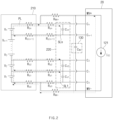
- FIG. 2 is a view of a general battery management apparatus.
- voltages Vi - V n of respective battery cells may be applied to capacitors C V1 - C Vn through sensing lines SL1 - SLn.
- a controller 120 e.g., the monitoring IC
- a voltage of a battery cell may be measured using voltages of the capacitors C V1 - Cvn.
- R MV of FIG. 2 may be a parasitic resistor of a driving current line PL
- R p may be a parasitic resistor of a sensing line SL.
- a driving current Ice of the controller 20 may be supplied from the battery module 210 and may flow through a path of the driving current line PL. While it is shown in FIG. 2 that the driving current source Ice 121 exists inside the controller 20, the driving current I CC 121 may be actually a current applied from the battery module 210.
- sensing lines SL1 - SLn may be separated from the driving current line PL outside the battery module 210 in the general battery management apparatus as shown in FIG. 2 (that is, R pn and R MV+ , R p0 and R MV- ), the sensing lines SL1 - SLn may not be separated from the driving current line PL inside the battery module 210.
- the current of the sensing lines SL1 - SLn and the driving current line PL flows in internal resistors R b0 and R bn located at opposite ends of the battery module 210 in FIG. 2 , and such a driving current has a high voltage value, resulting in voltage drops in R b0 and R bn .
- a significantly smaller voltage than V 1 and V n may be applied to C V1 and Cvn, such that voltages of battery cells located at the opposite ends of the battery module 210 may be measured lower than those of other battery cells at all times.
- FIG. 3 is a view of a battery management apparatus according to an embodiment disclosed herein.
- the battery management apparatus 100 may generate a switch control signal when the controller 120 generates a voltage measurement command for a battery cell.
- the controller 120 may turn off the switching unit 110 to control the driving current not to flow to the internal resistors R b0 and R bn of the battery module 120.
- the capacitors C V1 - C Vn of FIG. 3 have relatively small capacitances, and thus may be fixed to the voltages V 1 - V n of corresponding battery cells shortly after the switching unit 110 is turned off.
- the controller 120 may perform voltage measurement for each battery cell, and may accurately measure an actual voltage of a battery cell without an error caused by the internal resistors R b0 and R bn of the battery cells.
- the driving current of the controller 120 may be supplied from the power supply unit 130 C MV .
- the power supply unit 130 C MV may perform a function of preventing oscillation of a voltage of the battery module 210.
- the switching unit 110 may be turned on by a switch control signal of the controller 120 and the power supply unit 130 may start charging from the battery module 210.
- FIG. 4 is a view of a battery management apparatus according to another embodiment disclosed herein.
- the battery management apparatus 100 may internalize the switching unit 110 in the controller 120.
- the switching unit 110 is included in the controller 120, such that it is not necessary to transmit an additional switch control signal to the outside of the controller 120, and thus the controller 120 may have a function that is substantially the same as the battery management apparatus 100 without changing an external circuit of the controller 120.
- FIG. 4 a basic control operation of the battery management apparatus 100 shown in FIG. 4 is substantially the same as that of the battery management apparatus 100 of FIG. 3 , and thus a detailed description thereof will be omitted.
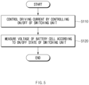
- FIG. 5 is a flowchart illustrating a control method of a battery management apparatus according to an embodiment disclosed herein.
- the control method of the battery management apparatus 100 may be a method of controlling a battery management apparatus including the switching unit 110 provided to control a driving current applied from a battery module and the controller 120 for controlling the driving current by controlling on/off of the switching unit 110.
- the driving current may be a current for driving the controller 120.
- the switching unit 110 may include at least one switch, and may be provided at one end of the battery module.
- the switching unit 110 may be provided outside or inside the controller 120.
- the battery management apparatus 100 may control the driving current by controlling on/off of the switching unit 110, in operation S110.
- the voltage of the battery cell may be measured according to an on/off state of the switching unit 110, in operation S120.
- the controller 120 may turn off the switching unit 110 such that the driving current does not flow to the internal resistor of the battery module.
- the internal resistor of the battery module may be an internal resistor of battery cells provided at opposite ends among a plurality of battery cells included in the battery module.
- the controller 120 may generate a control signal for turning off the switching unit 110.
- the generated control signal may be transferred to the switching unit 110 to control an operation of the switching unit 110.
- the control method of the battery management apparatus 100 may further include an operation of supplying the driving current to the controller 120 through the power supply unit 130.
- the power supply unit 130 may supply previously stored power to the controller 120.
- the power supply unit 130 may include a capacitor that may be charged by being supplied with power from the battery module when the switching unit 110 is in an on state.
- the power supply unit 130 may be charged with power being supplied from the battery module, and when the switching unit 110 is turned off, the power supply unit 130 may supply, to the controller 120, the charged power that serves as the driving current.
- a battery management method may increase accuracy and improve reliability in measuring a voltage of a battery cell by temporally separating a sensing line and a driving current line, which are shared for a battery module, from each other.
- FIG. 6 is a block diagram showing a hardware configuration of a computing system for performing a control method of a battery management apparatus, according to an embodiment disclosed herein.
- a computing system 1000 may include a microcontroller unit (MCU) 1010, a memory 1020, an input/output interface (I/F) 1030, and a communication I/F 1040.
- MCU microcontroller unit
- I/F input/output interface
- the MCU 1010 may be a processor that executes various programs (e.g., a battery cell voltage measurement program, a switching control program, etc.) stored in the memory 1020, processes various data including voltage, internal resistance, etc., of a battery cell through these programs, and performs the above-described functions of the battery management apparatus 100 shown in FIG. 1 .
- programs e.g., a battery cell voltage measurement program, a switching control program, etc.
- the memory 1020 may store various programs regarding voltage measurement, switching control, etc., of the battery cell. Moreover, the memory 1020 may store various data such as a voltage, an internal resistance, etc., of the battery cell.
- the memory 1020 may be provided in plural, depending on a need.
- the memory 1020 may be volatile memory or non-volatile memory.
- RAM random access memory
- DRAM dynamic RAM
- SRAM static RAM
- ROM read only memory
- PROM programmable ROM
- EAROM electrically alterable ROM
- EPROM erasable PROM
- EEPROM electrically erasable PROM
- flash memory etc.
- the above-listed examples of the memory 1020 are merely examples and are not limited thereto.
- the input/output I/F 1030 may provide an interface for transmitting and receiving data by connecting an input device (not shown) such as a keyboard, a mouse, a touch panel, etc., and an output device such as a display (not shown), etc., to the MCU 1010.
- an input device such as a keyboard, a mouse, a touch panel, etc.
- an output device such as a display (not shown), etc.
- the communication I/F 1040 which is a component capable of transmitting and receiving various data to and from a server, may be various devices capable of supporting wired or wireless communication. For example, a program for voltage measurement and switching control for a battery cell, various data, etc., may be transmitted and received to and from a separately provided external server through the communication I/F 1040.
- a computer program according to an embodiment disclosed herein may be recorded in the memory 1020 and processed by the MCU 1010, thus being implemented as a module that performs functions shown in FIG. 1 .
Landscapes
- Engineering & Computer Science (AREA)
- Power Engineering (AREA)
- Manufacturing & Machinery (AREA)
- Chemical & Material Sciences (AREA)
- Chemical Kinetics & Catalysis (AREA)
- Electrochemistry (AREA)
- General Chemical & Material Sciences (AREA)
- Microelectronics & Electronic Packaging (AREA)
- Charge And Discharge Circuits For Batteries Or The Like (AREA)
- Secondary Cells (AREA)
- Measurement Of Current Or Voltage (AREA)
- Tests Of Electric Status Of Batteries (AREA)
Abstract
Description
- This application claims priority to and the benefit of
Korean Patent Application No. 10-2021-0094503 filed in the Korean Intellectual Property Office on July 19, 2021 - Embodiments disclosed herein relate to a battery management apparatus and a battery system.
- A secondary battery is generally used as a battery pack including a battery module where a plurality of battery cells are connected to one another in series and/or in parallel. Battery packs may be managed and controlled by a battery management system (BMS) in terms of their states and operations.
- With the increasing demand for such battery packs, the importance of the BMS for managing a battery is growing. To simply perform a function of measuring a voltage of each battery cell among various functions of the BMS, a monitoring integrated circuit (IC) is used. A voltage of each battery cell is input through a sensing line such that the monitoring IC may periodically measure the voltage of the battery cell.
- In this case, a current for driving the monitoring IC is supplied from a battery module, and a big error occurs in measuring voltages of battery cells at opposite ends due to the current and an internal resistor of the battery module. Due to such an error, the voltages of the battery cells at the opposite ends of the battery module are measured lower than those of other battery cells, and a separate voltage measuring apparatus is required to correct the error.
- Embodiments disclosed herein aim to provide a battery management apparatus and a battery system capable of increasing accuracy and improving reliability in measuring a voltage of a battery cell by temporally separating a sensing line and a driving current line, which are shared for a battery module, from each other.
- Technical problems of the embodiments disclosed herein are not limited to the above-described technical problems, and other unmentioned technical problems would be clearly understood by one of ordinary skill in the art from the following description.
- A battery management apparatus according to an embodiment disclosed herein includes a switching unit configured to control electrical connection with a battery module and a controller configured to measure a voltage of a battery cell included in the battery module and to control a driving current transferred from the battery module by controlling on/off of the switching unit when the voltage of the battery cell is measured.
- According to an embodiment, when the switching unit is turned on, the battery module and the controller may be electrically connected to each other to transfer the driving current through an internal resistor of the battery module.
- According to an embodiment, the controller may be further configured to turn off the switching unit when the voltage of the battery cell is measured.
- According to an embodiment, the internal resistor of the battery module may be an internal resistor of battery cells provided at opposite ends among a plurality of battery cells included in the battery module.
- According to an embodiment, the controller may be further configured to generate a control signal for turning off the switching unit when the voltage of the battery cell is measured.
- According to an embodiment, the switching unit may be provided inside the controller.
- According to an embodiment, the driving current may be a driving current of the controller.
- According to an embodiment, the battery management apparatus may further include a power supply unit configured to supply the driving current to the controller.
- According to an embodiment, the power supply unit may be further configured to supply stored power to the controller when the switching unit is turned off by the controller.
- According to an embodiment, the power supply unit may include at least one capacitor.
- According to an embodiment, the capacitor of the power supply unit may be charged by being supplied with power from the battery module when the switching unit is in an on state.
- A battery system according to an embodiment disclosed herein includes a battery module including a plurality of battery cells, an electricity storage unit connected to the battery module to store a voltage of each battery cell, a switching unit provided between the battery module and a controller to control electrical connection between the battery module and the controller, and a controller configured to measure the voltage of the battery cell based on the voltage stored in the electricity storage unit and to control a driving current transferred from the battery module by controlling on/off of the switching unit when the voltage of the battery cell is measured.
- According to an embodiment, the electricity storage unit may include a plurality of capacitors provided to correspond to the battery cells, respectively.
- According to an embodiment, when the switching unit is turned on, the battery module and the controller may be electrically connected to each other to transfer the driving current through an internal resistor of the battery module.
- According to an embodiment, the controller may be further configured to turn off the switching unit when the voltage of the battery cell is measured.
- According to an embodiment, the battery system may further include a power supply unit connected to the controller to supply the driving current to the controller when the switching unit is turned off.
- According to an embodiment, the power supply unit may be further configured to supply stored power to the controller when the switching unit is turned off by the controller.
- According to an embodiment, the power supply unit may include at least one capacitor.
- A battery management apparatus and a battery system according to an embodiment disclosed herein may increase accuracy and improve reliability in measuring a voltage of a battery cell by temporally separating a sensing line and a driving current line, which are shared for a battery module, from each other.
-
-
FIG. 1 is a block diagram showing configurations of a battery management apparatus and a battery system including the same, according to an embodiment disclosed herein. -
FIG. 2 is a view of a conventional battery management apparatus. -
FIG. 3 is a view of a battery management apparatus according to an embodiment disclosed herein. -
FIG. 4 is a view of a battery management apparatus according to another embodiment disclosed herein. -
FIG. 5 is a flowchart illustrating a control method of a battery management apparatus according to an embodiment disclosed herein. -
FIG. 6 is a block diagram showing a hardware configuration of a computing system for performing a control method of a battery management apparatus, according to an embodiment disclosed herein. - Hereinafter, various embodiments disclosed herein will be described in detail with reference to the accompanying drawings. In this document, identical reference numerals will be used for identical components in the drawings, and the identical components will not be redundantly described.
- For various embodiments disclosed herein, specific structural or functional descriptions are only exemplified for the purpose of describing the embodiments, and various embodiments disclosed herein may be implemented in various forms, and should not be construed as being limited to the embodiments described herein.
- As used in various embodiments, the terms "1st, "2nd", "first", "second", or the like may modify various components regardless of importance, and do not limit the components. For example, a first component may be named as a second component without departing from the right scope of an embodiment disclosed herein, and similarly, the second component may be named as the first component.
- Terms used in the present document are used for only describing a specific exemplary embodiment of the disclosure and may not have an intention to limit the scope of other exemplary embodiments of the disclosure. It is to be understood that the singular forms include plural references unless the context clearly dictates otherwise.
- All terms including technical and scientific terms used herein have the same meaning as commonly understood by one of ordinary skill in the art to which the embodiments disclosed herein belong. It will be further understood that terms, such as those defined in commonly used dictionaries, should be interpreted as having a meaning that is consistent with their meaning in the context of the relevant art and will not be interpreted in an idealized or overly formal sense unless expressly so defined herein. In some cases, the terms defined herein may be interpreted to exclude embodiments disclosed herein.
-
FIG. 1 is a block diagram showing configurations of a battery management apparatus and a battery system including the same, according to an embodiment disclosed herein. - Referring to
FIG. 1 , abattery system 10 according to an embodiment disclosed herein may include abattery management apparatus 100, abattery module 210, and anelectricity storage unit 220. Thebattery management apparatus 100 according to an embodiment disclosed herein may include aswitching unit 110, acontroller 120, and apower supply unit 130. - The
switching unit 110 may be provided to control a driving current applied from thebattery module 210. Herein, the driving current may be a current for driving thecontroller 120. That is, theswitching unit 110 may be provided between thebattery module 210 and thecontroller 120 to control electrical connection between thebattery module 210 and thecontroller 120. In this case, when theswitching unit 210 is turned on, thebattery module 210 and thecontroller 120 may be electrically connected to each other such that a driving current may be transferred to thecontroller 120 through an internal resistor of thebattery module 210. Moreover, theswitching unit 110 may include at least one switch, and may be provided at one end of thebattery module 210. For example, theswitching unit 110 may be provided outside or inside thecontroller 120. - The
controller 120 may measure a voltage of each battery cell based on a voltage stored in theelectricity storage unit 220. When a voltage of each battery cell is measured, thecontroller 120 may control the driving current transferred from thebattery module 210 by controlling on/off of theswitching unit 110. When the voltage of the battery cell is measured, thecontroller 120 may turn off theswitching unit 110 such that the driving current does not flow from thebattery module 210. - That is, when the voltage of the battery cell included in the
battery module 210 is measured, thecontroller 120 may control the driving current by controlling on/off of theswitching unit 110. When the voltage of the battery cell is measured, thecontroller 120 may turn off theswitching unit 110 such that the driving current does not flow to the internal resistor of the battery module. For example, the internal resistor of thebattery module 210 may be an internal resistor of battery cells provided at opposite ends among a plurality of battery cells included in thebattery module 210. - When the voltage of the battery cell is measured, the
controller 120 may generate a control signal for turning off theswitching unit 110. The generated control signal may be transferred to theswitching unit 110 to control an operation of theswitching unit 110. For example, thecontroller 120 may include a monitoring integrated circuit (IC) provided in the battery management apparatus 50. - The
power supply unit 130 may supply the driving current to thecontroller 120. For example, when theswitching unit 110 is turned off by thecontroller 120, thepower supply unit 130 may supply previously stored power to thecontroller 120. For instance, thepower supply unit 130 may include a capacitor that may be charged by being supplied with power from thebattery module 210 when theswitching unit 110 is in an on state. - That is, when the
switching unit 110 is in the on state, thepower supply unit 130 may be charged with power being supplied from thebattery module 210, and when theswitching unit 110 is turned off, thepower supply unit 130 may provide the driving current to thecontroller 120 based on the charged power. - The
battery module 210 may include a plurality of battery cells. In this case, thebattery module 210 may include the plurality of battery cells and an internal resistor. - The
electricity storage unit 220 may be connected to thebattery module 210 to store a voltage of each battery cell. For example, theelectricity storage unit 220 may include a plurality of capacitors provided to correspond to respective battery cells. Thus, thecontroller 120 may detect a voltage of each battery cell by measuring a voltage stored in theelectricity storage unit 220. - As such, the
battery management apparatus 100 according to an embodiment disclosed herein may increase accuracy and improve reliability in measuring a voltage of a battery cell by temporally separating a sensing line and a driving current line (seeFIG. 3 ), which are shared for a battery module, from each other. This will be described in more detail below. -
FIG. 2 is a view of a general battery management apparatus. - Referring to
FIG. 2 , for the general battery management apparatus, voltages Vi - Vn of respective battery cells may be applied to capacitors CV1 - CVn through sensing lines SL1 - SLn. In this case, in a controller 120 (e.g., the monitoring IC), a voltage of a battery cell may be measured using voltages of the capacitors CV1 - Cvn. RMV ofFIG. 2 may be a parasitic resistor of a driving current line PL, and Rp may be a parasitic resistor of a sensing line SL. - Meanwhile, a driving current Ice of the controller 20 may be supplied from the
battery module 210 and may flow through a path of the driving current line PL. While it is shown inFIG. 2 that the drivingcurrent source Ice 121 exists inside the controller 20, the drivingcurrent I CC 121 may be actually a current applied from thebattery module 210. - While the sensing lines SL1 - SLn may be separated from the driving current line PL outside the
battery module 210 in the general battery management apparatus as shown inFIG. 2 (that is, Rpn and RMV+, Rp0 and RMV-), the sensing lines SL1 - SLn may not be separated from the driving current line PL inside thebattery module 210. - As such, the current of the sensing lines SL1 - SLn and the driving current line PL flows in internal resistors Rb0 and Rbn located at opposite ends of the
battery module 210 inFIG. 2 , and such a driving current has a high voltage value, resulting in voltage drops in Rb0 and Rbn. Thus, a significantly smaller voltage than V1 and Vn may be applied to CV1 and Cvn, such that voltages of battery cells located at the opposite ends of thebattery module 210 may be measured lower than those of other battery cells at all times. -
FIG. 3 is a view of a battery management apparatus according to an embodiment disclosed herein. - Referring to
FIG. 3 , thebattery management apparatus 100 according to an embodiment disclosed herein may generate a switch control signal when thecontroller 120 generates a voltage measurement command for a battery cell. Thus, thecontroller 120 may turn off theswitching unit 110 to control the driving current not to flow to the internal resistors Rb0 and Rbn of thebattery module 120. - The capacitors CV1 - CVn of
FIG. 3 have relatively small capacitances, and thus may be fixed to the voltages V1 - Vn of corresponding battery cells shortly after theswitching unit 110 is turned off. Thecontroller 120 may perform voltage measurement for each battery cell, and may accurately measure an actual voltage of a battery cell without an error caused by the internal resistors Rb0 and Rbn of the battery cells. - Meanwhile, when the
controller 120 measures a voltage of each battery cell (that is, theswitching unit 110 is in an off state), the driving current of thecontroller 120 may be supplied from thepower supply unit 130 CMV. The power supply unit 130 CMV may perform a function of preventing oscillation of a voltage of thebattery module 210. - When the
controller 120 has completed voltage measurement for a battery cell, theswitching unit 110 may be turned on by a switch control signal of thecontroller 120 and thepower supply unit 130 may start charging from thebattery module 210. -
FIG. 4 is a view of a battery management apparatus according to another embodiment disclosed herein. - Referring to
FIG. 4 , thebattery management apparatus 100 according to an embodiment disclosed herein may internalize theswitching unit 110 in thecontroller 120. In this case, theswitching unit 110 is included in thecontroller 120, such that it is not necessary to transmit an additional switch control signal to the outside of thecontroller 120, and thus thecontroller 120 may have a function that is substantially the same as thebattery management apparatus 100 without changing an external circuit of thecontroller 120. - Meanwhile, a basic control operation of the
battery management apparatus 100 shown inFIG. 4 is substantially the same as that of thebattery management apparatus 100 ofFIG. 3 , and thus a detailed description thereof will be omitted. -
FIG. 5 is a flowchart illustrating a control method of a battery management apparatus according to an embodiment disclosed herein. - The control method of the
battery management apparatus 100 according to an embodiment disclosed herein inFIG. 5 may be a method of controlling a battery management apparatus including theswitching unit 110 provided to control a driving current applied from a battery module and thecontroller 120 for controlling the driving current by controlling on/off of theswitching unit 110. Herein, the driving current may be a current for driving thecontroller 120. Moreover, theswitching unit 110 may include at least one switch, and may be provided at one end of the battery module. For example, theswitching unit 110 may be provided outside or inside thecontroller 120. - Referring to
FIG. 5 , thebattery management apparatus 100 according to an embodiment disclosed herein may control the driving current by controlling on/off of theswitching unit 110, in operation S110. The voltage of the battery cell may be measured according to an on/off state of theswitching unit 110, in operation S120. - More specifically, in the control method of the
battery management apparatus 100 according to an embodiment disclosed herein, when the voltage of the battery cell is measured through thecontroller 120, thecontroller 120 may turn off theswitching unit 110 such that the driving current does not flow to the internal resistor of the battery module. For example, the internal resistor of the battery module may be an internal resistor of battery cells provided at opposite ends among a plurality of battery cells included in the battery module. - When the voltage of the battery cell is measured in operation S120, the
controller 120 may generate a control signal for turning off theswitching unit 110. The generated control signal may be transferred to theswitching unit 110 to control an operation of theswitching unit 110. - Although not shown in
FIG. 5 , the control method of thebattery management apparatus 100 according to an embodiment disclosed herein may further include an operation of supplying the driving current to thecontroller 120 through thepower supply unit 130. For example, when theswitching unit 110 is turned off by thecontroller 120, thepower supply unit 130 may supply previously stored power to thecontroller 120. In this case, thepower supply unit 130 may include a capacitor that may be charged by being supplied with power from the battery module when theswitching unit 110 is in an on state. - That is, when the
switching unit 110 is in the on state, thepower supply unit 130 may be charged with power being supplied from the battery module, and when theswitching unit 110 is turned off, thepower supply unit 130 may supply, to thecontroller 120, the charged power that serves as the driving current. - As such, a battery management method according to an embodiment disclosed herein may increase accuracy and improve reliability in measuring a voltage of a battery cell by temporally separating a sensing line and a driving current line, which are shared for a battery module, from each other.
-
FIG. 6 is a block diagram showing a hardware configuration of a computing system for performing a control method of a battery management apparatus, according to an embodiment disclosed herein. - Referring to
FIG. 6 , acomputing system 1000 according to an embodiment disclosed herein may include a microcontroller unit (MCU) 1010, amemory 1020, an input/output interface (I/F) 1030, and a communication I/F 1040. - The
MCU 1010 may be a processor that executes various programs (e.g., a battery cell voltage measurement program, a switching control program, etc.) stored in thememory 1020, processes various data including voltage, internal resistance, etc., of a battery cell through these programs, and performs the above-described functions of thebattery management apparatus 100 shown inFIG. 1 . - The
memory 1020 may store various programs regarding voltage measurement, switching control, etc., of the battery cell. Moreover, thememory 1020 may store various data such as a voltage, an internal resistance, etc., of the battery cell. - The
memory 1020 may be provided in plural, depending on a need. Thememory 1020 may be volatile memory or non-volatile memory. For thememory 1020 as the volatile memory, random access memory (RAM), dynamic RAM (DRAM), static RAM (SRAM), etc., may be used. For thememory 1020 as the nonvolatile memory, read only memory (ROM), programmable ROM (PROM), electrically alterable ROM (EAROM), erasable PROM (EPROM), electrically erasable PROM (EEPROM), flash memory, etc., may be used. The above-listed examples of thememory 1020 are merely examples and are not limited thereto. - The input/output I/
F 1030 may provide an interface for transmitting and receiving data by connecting an input device (not shown) such as a keyboard, a mouse, a touch panel, etc., and an output device such as a display (not shown), etc., to theMCU 1010. - The communication I/
F 1040, which is a component capable of transmitting and receiving various data to and from a server, may be various devices capable of supporting wired or wireless communication. For example, a program for voltage measurement and switching control for a battery cell, various data, etc., may be transmitted and received to and from a separately provided external server through the communication I/F 1040. - As such, a computer program according to an embodiment disclosed herein may be recorded in the
memory 1020 and processed by theMCU 1010, thus being implemented as a module that performs functions shown inFIG. 1 . - Even though all components constituting an embodiment disclosed herein have been described above as being combined into one or operating in combination, the embodiments disclosed herein are not necessarily limited to the embodiments. That is, within the object scope of the embodiments disclosed herein, all the components may operate by being selectively combined into one or more.
- Moreover, terms such as "include", "constitute" or "have" described above may mean that the corresponding component may be inherent unless otherwise stated, and thus should be construed as further including other components rather than excluding other components. All terms including technical or scientific terms have the same meanings as those generally understood by those of ordinary skill in the art to which the embodiments disclosed herein pertain, unless defined otherwise. The terms used generally like terms defined in dictionaries should be interpreted as having meanings that are the same as the contextual meanings of the relevant technology and should not be interpreted as having ideal or excessively formal meanings unless they are clearly defined in the present document.
- The above description is merely illustrative of the technical idea of the present disclosure, and various modifications and variations will be possible without departing from the essential characteristics of embodiments of the present disclosure by those of ordinary skill in the art to which the embodiments disclosed herein pertains. Therefore, the embodiments disclosed herein are intended for description rather than limitation of the technical spirit of the embodiments disclosed herein and the scope of the technical spirit of the present disclosure is not limited by these embodiments disclosed herein. The protection scope of the technical spirit disclosed herein should be interpreted by the following claims, and all technical spirits within the same range should be understood to be included in the range of the present document.
Claims (18)
- A battery management apparatus comprising:a switching unit configured to control electrical connection with a battery module; anda controller configured to measure a voltage of a battery cell included in the battery module and to control a driving current transferred from the battery module by controlling on/off of the switching unit when the voltage of the battery cell is measured.
- The battery management apparatus of claim 1, wherein when the switching unit is turned on, the battery module and the controller are electrically connected to each other to transfer the driving current through an internal resistor of the battery module.
- The battery management apparatus of claim 1, wherein the controller is further configured to turn off the switching unit when the voltage of the battery cell is measured.
- The battery management apparatus of claim 1, wherein the internal resistor of the battery module is an internal resistor of battery cells provided at opposite ends among a plurality of battery cells included in the battery module.
- The battery management apparatus of claim 1, wherein the controller is further configured to generate a control signal to turn off the switching unit when the voltage of the battery cell is measured.
- The battery management apparatus of claim 1, wherein the switching unit is provided inside the controller.
- The battery management apparatus of claim 1, wherein the driving current is a driving current of the controller.
- The battery management apparatus of claim 1, further comprising a power supply unit configured to supply the driving current to the controller.
- The battery management apparatus of claim 8, wherein the power supply unit is further configured to supply stored power to the controller when the switching unit is turned off by the controller.
- The battery management apparatus of claim 8, wherein the power supply unit comprises at least one capacitor.
- The battery management apparatus of claim 10, wherein the capacitor of the power supply unit is configured to charge by being supplied with power from the battery module when the switching unit is in an on state.
- A battery system comprising:a battery module comprising a plurality of battery cells;an electricity storage unit connected to the battery module to store a voltage of each battery cell;a switching unit provided between the battery module and a controller to control electrical connection between the battery module and the controller; anda controller configured to measure the voltage of the battery cell based on the voltage stored in the electricity storage unit and to control a driving current transferred from the battery module by controlling on/off of the switching unit when the voltage of the battery cell is measured.
- The battery system of claim 12, wherein the electricity storage unit comprises a plurality of capacitors provided to correspond to the battery cells, respectively.
- The battery system of claim 12, wherein when the switching unit is turned on, the battery module and the controller are electrically connected to each other to transfer the driving current through an internal resistor of the battery module.
- The battery system of claim 1, wherein the controller is further configured to turn off the switching unit when the voltage of the battery cell is measured.
- The battery system of claim 12, further comprising a power supply unit connected to the controller to supply the driving current to the controller when the switching unit is turned off.
- The battery system of claim 16, wherein the power supply unit is further configured to supply stored power to the controller when the switching unit is turned off by the controller.
- The battery system of claim 16, wherein the power supply unit comprises at least one capacitor.
Applications Claiming Priority (2)
| Application Number | Priority Date | Filing Date | Title |
|---|---|---|---|
| KR1020210094503A KR102884063B1 (en) | 2021-07-19 | 2021-07-19 | Battery management apparatus and battery system |
| PCT/KR2022/010028 WO2023003241A1 (en) | 2021-07-19 | 2022-07-11 | Device for managing battery, and battery system |
Publications (3)
| Publication Number | Publication Date |
|---|---|
| EP4231485A1 true EP4231485A1 (en) | 2023-08-23 |
| EP4231485A4 EP4231485A4 (en) | 2024-07-03 |
| EP4231485B1 EP4231485B1 (en) | 2026-04-15 |
Family
ID=84980275
Family Applications (1)
| Application Number | Title | Priority Date | Filing Date |
|---|---|---|---|
| EP22846113.3A Active EP4231485B1 (en) | 2021-07-19 | 2022-07-11 | Device for managing battery, and battery system |
Country Status (6)
| Country | Link |
|---|---|
| US (1) | US20240097475A1 (en) |
| EP (1) | EP4231485B1 (en) |
| JP (1) | JP7635478B2 (en) |
| KR (1) | KR102884063B1 (en) |
| CN (1) | CN116547885A (en) |
| WO (1) | WO2023003241A1 (en) |
Family Cites Families (22)
| Publication number | Priority date | Publication date | Assignee | Title |
|---|---|---|---|---|
| JP2840415B2 (en) * | 1990-09-13 | 1998-12-24 | キヤノン株式会社 | Charging device |
| US5677077A (en) * | 1996-02-22 | 1997-10-14 | Compaq Computer Corporation | Sensor circuit for providing maximum and minimum cell voltages of a battery |
| JP2007276654A (en) * | 2006-04-07 | 2007-10-25 | Shin Kobe Electric Mach Co Ltd | Battery state detection system and automobile |
| JP2007333474A (en) * | 2006-06-13 | 2007-12-27 | Nissan Motor Co Ltd | Open voltage detection device and open voltage detection method |
| JP4388094B2 (en) * | 2007-03-28 | 2009-12-24 | 株式会社東芝 | Battery pack protection device and battery pack device |
| KR101107999B1 (en) * | 2007-10-16 | 2012-01-25 | 한국과학기술원 | Battery Operating System Combines Voltage Sensor and Charge Uniformity |
| JP2010117256A (en) * | 2008-11-13 | 2010-05-27 | Toshiba Toko Meter Systems Co Ltd | Battery lifetime prediction apparatus |
| JP2011176987A (en) * | 2010-02-25 | 2011-09-08 | Hitachi Kokusai Electric Inc | Power supply apparatus |
| JP6103798B2 (en) * | 2010-12-22 | 2017-03-29 | ミツミ電機株式会社 | Flying capacitor type voltage detection circuit and integrated circuit for battery protection |
| JP6019830B2 (en) * | 2012-07-05 | 2016-11-02 | 株式会社豊田自動織機 | CHARGE CONTROL DEVICE, BATTERY PACK, AND CHARGE CONTROL METHOD |
| JP2014219239A (en) * | 2013-05-06 | 2014-11-20 | 株式会社デンソー | Voltage measurement device |
| KR101647694B1 (en) * | 2014-12-15 | 2016-08-23 | 현대오트론 주식회사 | Apparatus for measuring voltage and method thereof |
| KR101871267B1 (en) * | 2016-01-27 | 2018-06-27 | 엘지전자 주식회사 | Battery charging device and cleaner including the same |
| US10104745B2 (en) * | 2016-03-18 | 2018-10-16 | General Electric Company | Power handling system and method |
| CN107546786B (en) * | 2016-06-27 | 2023-12-29 | 深圳市华思旭科技有限公司 | Power supply device and power supply method |
| KR101991910B1 (en) * | 2016-11-16 | 2019-06-21 | 주식회사 엘지화학 | Apparatus and method for measuring isolation resistance of battery |
| KR102256601B1 (en) * | 2017-11-07 | 2021-06-02 | 주식회사 엘지에너지솔루션 | BMS Wake-up Apparatus, BMS and Battery pack including the same |
| JP7207074B2 (en) * | 2019-03-27 | 2023-01-18 | 株式会社Gsユアサ | BATTERY MANAGEMENT DEVICE, POWER STORAGE DEVICE, BATTERY MANAGEMENT METHOD, AND COMPUTER PROGRAM |
| DE102019129170A1 (en) * | 2019-10-29 | 2021-04-29 | Volkswagen Aktiengesellschaft | Control arrangement for a high-voltage battery and method for operating a control arrangement |
| WO2021111822A1 (en) * | 2019-12-04 | 2021-06-10 | 株式会社デンソー | Battery monitoring device |
| TWI780392B (en) * | 2019-12-31 | 2022-10-11 | 位速科技股份有限公司 | energy storage system |
| US20230006454A1 (en) * | 2020-01-02 | 2023-01-05 | K2 Energy Solutions, Inc. | Very Low Power Standby Circuit Such As For A Battery Management System |
-
2021
- 2021-07-19 KR KR1020210094503A patent/KR102884063B1/en active Active
-
2022
- 2022-07-11 CN CN202280007525.0A patent/CN116547885A/en active Pending
- 2022-07-11 EP EP22846113.3A patent/EP4231485B1/en active Active
- 2022-07-11 WO PCT/KR2022/010028 patent/WO2023003241A1/en not_active Ceased
- 2022-07-11 JP JP2023534080A patent/JP7635478B2/en active Active
- 2022-07-11 US US18/039,596 patent/US20240097475A1/en active Pending
Also Published As
| Publication number | Publication date |
|---|---|
| JP2023554607A (en) | 2023-12-28 |
| EP4231485B1 (en) | 2026-04-15 |
| WO2023003241A1 (en) | 2023-01-26 |
| EP4231485A4 (en) | 2024-07-03 |
| JP7635478B2 (en) | 2025-02-26 |
| CN116547885A (en) | 2023-08-04 |
| KR102884063B1 (en) | 2025-11-07 |
| KR20230013577A (en) | 2023-01-26 |
| US20240097475A1 (en) | 2024-03-21 |
Similar Documents
| Publication | Publication Date | Title |
|---|---|---|
| US20150032394A1 (en) | Power management system | |
| US10309841B2 (en) | Temperature detecting apparatus | |
| US20240175937A1 (en) | Battery management apparatus and method | |
| EP3002599B1 (en) | Method for correcting voltage sensor included in battery rack | |
| JP2012242135A (en) | Residual capacity calculation method, pre-shipment adjustment method of packed battery, residual capacity calculation device, and packed battery | |
| KR20150131977A (en) | Battery remaining power predicting device and battery pack | |
| CN115332648A (en) | Battery management system and battery system | |
| US10416744B2 (en) | Data processing apparatus, structure and power generation apparatus including the same | |
| CN113270649B (en) | Battery control device, battery control method, storage medium, and vehicle | |
| EP4231485A1 (en) | Device for managing battery, and battery system | |
| KR102044808B1 (en) | Battery control system and driving method of the same | |
| US11476696B2 (en) | Charge and discharge control apparatus and electronic device | |
| EP4246160A1 (en) | Battery management device and method | |
| EP4653892A1 (en) | Battery diagnosis device and battery diagnosis method | |
| US11448703B2 (en) | Device and method for estimating SOC via open-circuit voltage of battery | |
| KR101556033B1 (en) | Method of correcting measuring voltage error for charger and discharger | |
| EP4567447A1 (en) | Battery management apparatus and operation method therefor | |
| US20180173292A1 (en) | Battery pack and method for controlling discharge from secondary battery | |
| EP4325232A1 (en) | Battery management device and operating method therefor | |
| US20240421369A1 (en) | Battery pack and operating method thereof | |
| EP4624960A1 (en) | Battery lifespan estimation device and method | |
| US20240154185A1 (en) | Battery management apparatus and operating method thereof | |
| US20250298451A1 (en) | Power supply management circuit, memory system, and power supply management method |
Legal Events
| Date | Code | Title | Description |
|---|---|---|---|
| STAA | Information on the status of an ep patent application or granted ep patent |
Free format text: STATUS: THE INTERNATIONAL PUBLICATION HAS BEEN MADE |
|
| PUAI | Public reference made under article 153(3) epc to a published international application that has entered the european phase |
Free format text: ORIGINAL CODE: 0009012 |
|
| STAA | Information on the status of an ep patent application or granted ep patent |
Free format text: STATUS: REQUEST FOR EXAMINATION WAS MADE |
|
| 17P | Request for examination filed |
Effective date: 20230516 |
|
| AK | Designated contracting states |
Kind code of ref document: A1 Designated state(s): AL AT BE BG CH CY CZ DE DK EE ES FI FR GB GR HR HU IE IS IT LI LT LU LV MC MK MT NL NO PL PT RO RS SE SI SK SM TR |
|
| A4 | Supplementary search report drawn up and despatched |
Effective date: 20240603 |
|
| RIC1 | Information provided on ipc code assigned before grant |
Ipc: H01M 10/42 20060101ALI20240527BHEP Ipc: G01R 31/36 20200101ALI20240527BHEP Ipc: H02J 7/34 20060101ALI20240527BHEP Ipc: H02J 7/00 20060101AFI20240527BHEP |
|
| DAV | Request for validation of the european patent (deleted) | ||
| DAX | Request for extension of the european patent (deleted) | ||
| STAA | Information on the status of an ep patent application or granted ep patent |
Free format text: STATUS: EXAMINATION IS IN PROGRESS |
|
| 17Q | First examination report despatched |
Effective date: 20250512 |
|
| GRAP | Despatch of communication of intention to grant a patent |
Free format text: ORIGINAL CODE: EPIDOSNIGR1 |
|
| STAA | Information on the status of an ep patent application or granted ep patent |
Free format text: STATUS: GRANT OF PATENT IS INTENDED |
|
| INTG | Intention to grant announced |
Effective date: 20251218 |
|
| GRAS | Grant fee paid |
Free format text: ORIGINAL CODE: EPIDOSNIGR3 |
|
| GRAA | (expected) grant |
Free format text: ORIGINAL CODE: 0009210 |
|
| STAA | Information on the status of an ep patent application or granted ep patent |
Free format text: STATUS: THE PATENT HAS BEEN GRANTED |
|
| P01 | Opt-out of the competence of the unified patent court (upc) registered |
Free format text: CASE NUMBER: UPC_APP_0005728_4231485/2026 Effective date: 20260217 |
|
| AK | Designated contracting states |
Kind code of ref document: B1 Designated state(s): AL AT BE BG CH CY CZ DE DK EE ES FI FR GB GR HR HU IE IS IT LI LT LU LV MC MK MT NL NO PL PT RO RS SE SI SK SM TR |
|
| REG | Reference to a national code |
Ref country code: CH Ref legal event code: F10 Free format text: ST27 STATUS EVENT CODE: U-0-0-F10-F00 (AS PROVIDED BY THE NATIONAL OFFICE) Effective date: 20260415 |