EP4231472B1 - Datenausrichtungsverfahren, differenzialschutz und differenzialschutzsystem - Google Patents
Datenausrichtungsverfahren, differenzialschutz und differenzialschutzsystem Download PDFInfo
- Publication number
- EP4231472B1 EP4231472B1 EP23305083.0A EP23305083A EP4231472B1 EP 4231472 B1 EP4231472 B1 EP 4231472B1 EP 23305083 A EP23305083 A EP 23305083A EP 4231472 B1 EP4231472 B1 EP 4231472B1
- Authority
- EP
- European Patent Office
- Prior art keywords
- time
- differential
- protector
- differential protector
- time node
- Prior art date
- Legal status (The legal status is an assumption and is not a legal conclusion. Google has not performed a legal analysis and makes no representation as to the accuracy of the status listed.)
- Active
Links
Images

Classifications
-
- G—PHYSICS
- G06—COMPUTING OR CALCULATING; COUNTING
- G06F—ELECTRIC DIGITAL DATA PROCESSING
- G06F1/00—Details not covered by groups G06F3/00 - G06F13/00 and G06F21/00
- G06F1/04—Generating or distributing clock signals or signals derived directly therefrom
- G06F1/12—Synchronisation of different clock signals provided by a plurality of clock generators
-
- H—ELECTRICITY
- H02—GENERATION; CONVERSION OR DISTRIBUTION OF ELECTRIC POWER
- H02H—EMERGENCY PROTECTIVE CIRCUIT ARRANGEMENTS
- H02H3/00—Emergency protective circuit arrangements for automatic disconnection directly responsive to an undesired change from normal electric working condition with or without subsequent reconnection ; integrated protection
- H02H3/26—Emergency protective circuit arrangements for automatic disconnection directly responsive to an undesired change from normal electric working condition with or without subsequent reconnection ; integrated protection responsive to difference between voltages or between currents; responsive to phase angle between voltages or between currents
- H02H3/28—Emergency protective circuit arrangements for automatic disconnection directly responsive to an undesired change from normal electric working condition with or without subsequent reconnection ; integrated protection responsive to difference between voltages or between currents; responsive to phase angle between voltages or between currents involving comparison of the voltage or current values at two spaced portions of a single system, e.g. at opposite ends of one line, at input and output of apparatus
-
- H—ELECTRICITY
- H02—GENERATION; CONVERSION OR DISTRIBUTION OF ELECTRIC POWER
- H02H—EMERGENCY PROTECTIVE CIRCUIT ARRANGEMENTS
- H02H1/00—Details of emergency protective circuit arrangements
- H02H1/0061—Details of emergency protective circuit arrangements concerning transmission of signals
-
- H—ELECTRICITY
- H02—GENERATION; CONVERSION OR DISTRIBUTION OF ELECTRIC POWER
- H02H—EMERGENCY PROTECTIVE CIRCUIT ARRANGEMENTS
- H02H7/00—Emergency protective circuit arrangements specially adapted for specific types of electric machines or apparatus or for sectionalised protection of cable or line systems, and effecting automatic switching in the event of an undesired change from normal working conditions
- H02H7/26—Sectionalised protection of cable or line systems, e.g. for disconnecting a section on which a short-circuit, earth fault, or arc discharge has occured
- H02H7/261—Sectionalised protection of cable or line systems, e.g. for disconnecting a section on which a short-circuit, earth fault, or arc discharge has occured involving signal transmission between at least two stations
- H02H7/263—Sectionalised protection of cable or line systems, e.g. for disconnecting a section on which a short-circuit, earth fault, or arc discharge has occured involving signal transmission between at least two stations involving transmissions of measured values
-
- H—ELECTRICITY
- H02—GENERATION; CONVERSION OR DISTRIBUTION OF ELECTRIC POWER
- H02H—EMERGENCY PROTECTIVE CIRCUIT ARRANGEMENTS
- H02H7/00—Emergency protective circuit arrangements specially adapted for specific types of electric machines or apparatus or for sectionalised protection of cable or line systems, and effecting automatic switching in the event of an undesired change from normal working conditions
- H02H7/26—Sectionalised protection of cable or line systems, e.g. for disconnecting a section on which a short-circuit, earth fault, or arc discharge has occured
- H02H7/261—Sectionalised protection of cable or line systems, e.g. for disconnecting a section on which a short-circuit, earth fault, or arc discharge has occured involving signal transmission between at least two stations
Definitions
- Embodiments of the present disclosure relates to a data alignment method for a differential protector, a differential protector, and a differential protection system.
- differential protection is often used to realize protection of devices as well as power lines.
- a differential protector needs to obtain current sample data from each end (two or more ends) of a differential protection area, and these current sample values must be aligned in time.
- the differential protector receives current information directly from a current transformer, and thus the differential protector obtains the current information in a negligible amount of time.
- current values collected by the current transformer are first transmitted to the merging unit, which then transmits them to the differential protector via a network communication method such as a process bus.
- the delay caused by the merging unit is uncertain and the differential protector takes additional time to try to obtain the delay of the merging unit connected to other differential protectors, resulting in longer response times for subsequent operations. If both the merging unit and the differential protector are time-synchronized with each other, the delay caused by the merging unit can be eliminated by calculation. However, if the time synchronization of the differential protector is broken, the delay caused by the merging unit combined with the uncertainty of the time information makes it difficult to realize correct differential protection in this case.
- the present invention provides a data alignment method, a differential protector, and a differential protection system, which can solve the technical problem that it is difficult to realize differential protection correctly when differential protectors lose time synchronization.
- the present invention provides a data alignment method for a first differential protector, comprising: obtaining, at a first time node tA, first sampled current data from a first sampling device; transmitting a first message to a second differential protector after a first transmission processing delay ta, the first message comprising the first sampled current data; receiving, at a first moment tA*, a second message from the second differential protector, the second message comprising second sampled current data and its sampling time stamp, first time information of the second differential protector related to a difference in time of reception tc from receipt of the first message to a second time node, and second time information of the second differential protector related to a second transmission processing delay td from the second time node to transmission of the second message, the second time node being a time point when a second sampling device obtains the second sampled current data; when the first differential protector is in time synchronization with the second differential protector, determining a third time node at which the first differential protector obtains third sampled current data corresponding to the sampling time
- the method when the first differential protector is in time synchronization with the second differential protector, the method further comprises: calculating and storing the time calculation deviation tmem whenever a time synchronization signal is received or calculating and storing the time calculation deviation tmem whenever the sampled current data from the first sampling device is received.
- the second message further indicates that the second differential protector loses time synchronization or regains time synchronization.
- the first sampling device is a first merging unit
- the second sampling device is a second merging unit
- the first merging unit and the second merging unit obtain sampled current values from different locations of the same power line respectively.
- the first differential protector and the second differential protector use satellite timing to maintain time synchronization.
- At least one embodiment of the present disclosure provides a differential protector comprising a processor and a memory having program codes stored thereon, the program codes, when executed by the processor, perform the data alignment method as described in any one of the above embodiments.
- the present invention also provides a differential protection system for a power line, comprising: a first sampling device and a second sampling device configured to obtain sampled current values from different locations at the power line, respectively; a first differential protector, connected to the first sampling device, and configured to receive first sampled current data transmitted by the first sampling device; and a second differential protector, connected to the second sampling device, and configured to receive second sampled current data transmitted by the second sampling device, wherein the first differential protector and the second differential protector are each the differential protector as described in the above embodiments.
- Words such as “connected” or “linked” are not limited to physical or mechanical connections, but may include electrical connections, whether direct or indirect.
- the terms “up”, “down”, “left”, “right”, etc. are used only to indicate relative position relationships, and when the absolute position of the object being described changes, the relative position relationship may also change accordingly.
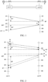
- FIG. 1 illustrates a timing schematic diagram of a differential protection scheme and a data alignment scheme without transmission processing delay of current data.
- a and B are noted as the two ends of the power line.
- Differential protector A and differential protector B are used at end A and end B respectively.
- Both differential protector A and differential protector B can directly use current mutual inductance to sense the current in the power line, so that there is almost no delay between the time when the differential protector A and the differential protector B obtain current data and the time of real current.
- the differential protector A and the differential protector B transmit data to each other through a communication link. In the absence of time synchronization between the differential protector A and the differential protector B, data alignment can be realized by eliminating communication delays, i.e., asynchronous alignment.
- a time node tAn and a time node tBn are the moments when the current is sampled from the power line by the differential protector A and the differential protector B, and in the scheme of FIG. 1 , it is considered that sampling of the current and transmission of sampled current data occur at the same moment, that is, there is no transmission processing delay in the circuit data.
- Communication delay can be determined by an average value of communication time.
- the differential protector A transmits message 1 to the differential protector B at time node tA1, and the message 1 includes the current data sampled at time point tA1.
- the differential protector B transmits message 2 to the differential protector A at time node tB3, and the message 2 includes the current data sampled at time point tB3.
- tp1 is a transmission delay from the differential protector A to the differential protector B (which may also be referred to as propagation delay, communication delay, etc.)
- tp2 is a transmission delay from the differential protector B to the differential protector A.
- tc is a duration between a moment tB* at which differential protector B receives the message 1 and the time node tB3, and tA* is a moment at which differential protector A receives the message 2.
- Message 2 may also include tc.
- the tB3 * can be considered as an estimated value of a time point at which the differential protector A collects the current data that needs to be aligned with the current data sampled by the differential protector at time point tB3. Therefore, the current data collected at a time node of the time nodes tAn that is closest to tB3* is the current data aligned with the current data collected at time point tB3.
- the differential protector does not obtain current values of the power line directly from the current mutual inductance, instead, a sampling device, such as a merging unit, samples and preliminarily processes current values collected by a current transformer, and then the sampling device transmits processed sampled current data to the differential protector through the process bus.
- a sampling device such as a merging unit
- the sampling device transmits processed sampled current data to the differential protector through the process bus.
- the presence of the sampling device causes a delay from conducting sampling to receiving the sampled data by the differential protector, which may include a delay from the sampling to obtaining the sampled current data by the sampling device and a network transmission delay for transmitting the sampled current data to the differential protector over the network.
- the delay may exceed an allowable error range and may be time varying. Therefore, the asynchronous alignment method in FIG. 1 is not applicable to scenarios where the process bus is used.
- a differential protection scheme for synchronous alignment can be used.
- differential protectors A and B and their sampling devices are time-synchronized by the same satellite positioning system, so that current data sampled at the same time node in different differential protectors can be determined based on the same time stamp.
- the differential protection scheme for synchronous alignment must ensure that time synchronization is not lost, and data alignment cannot be realized once time synchronization is lost.
- the time synchronization is lost, only asynchronous alignment can be used, and the asynchronous alignment scheme in FIG. 1 does not realize good data alignment for situations where there are delays in obtaining of current data and/or in transmission processing (e.g., scenarios using the process bus).
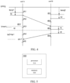
- FIG. 2 illustrates a timing schematic diagram of a data alignment scheme with transmission processing delay of current data.
- the differential protectors and sampling devices at the ends A and B can be physically synchronized by, for example, a GPS satellite positioning system, a satellite positioning module for example can generate a Pulse Per Second (PPS) signal at regular intervals for time alignment. Therefore, current sampling moments at both end A and end B can be based on the PPS signal. For example, both end A and end B can sequentially label the current data sampled between the two PPS signals. The same labeled current data indicates the current data collected at the same time. In the case of time synchronization, alignment can be performed according to the label of the current data.
- PPS Pulse Per Second
- differential protector A and differential protector B can use the scheme of FIG. 1 to realize data alignment, but there are errors in the alignment due to delays in the transmission processing of the data.
- differential protector A receives the current data at time node tA1 and transmits message 1 to the differential protector B after a delay ta.
- the differential protector B receives the message 1 at moment tB*.
- the differential protector B needs to wait for the time node tB3 for the next obtaining of the sampled data, and there is a time duration tc between them.
- the differential protector B Similar to the differential protector A, the differential protector B has a transmission processing delay td from obtaining the sampled data to actually transmitting the message.
- the differential protector B actually transmits the message 2 at moment tB3 *, and the differential protector A receives the message 2 at moment tA*. If the estimated value of tB3* and its corresponding current data at end A are still calculated according to the asynchronous alignment method of FIG. 1 , there will be deviations.
- the embodiments of the present disclosure provide a data alignment method, a differential protector, and a differential protection system which can correctly perform differential protection when the differential protectors lose time synchronization.
- FIG. 3 illustrates a flowchart of a data alignment method for a first differential protector provided in accordance with at least one embodiment of the present disclosure.
- the data alignment method includes the following steps:
- FIG. 4 illustrates a timing schematic diagram of a data alignment method provided in at least one embodiment of the present disclosure.
- the method in FIG. 3 will be described below with reference to the timing schematic diagram of the data alignment method in FIG. 4 .
- the first message is noted as message 1
- the second message is noted as message 2
- the first differential protector is noted as differential protector A
- the second differential protector is noted as differential protector B.
- the differential protector involved in the present disclosure may be, for example, a relay. It is understood that although only two differential protectors are shown in FIG. 4 , there may be cases where more than or equal to three differential protectors communicate with each other and perform the data alignment method as in FIG. 3 . However, in the case where more than three differential protectors communicate with each other, any two differential protectors perform the data alignment method with each other in the same manner as described in connection with FIG. 4 and will not be described herein.
- the differential protector A and the differential protector B and their first and second sampling devices may use satellite timing to maintain time synchronization, such as GPS, BeiDou, Galileo and other satellites. Satellites can transmit PPS signals to the differential protector A and the differential protector B to realize time synchronization. Time synchronization can also be realized by any other periodic time synchronization signal with fixed duration.
- maintaining time synchronization between the differential protector A and the differential protector B includes maintaining time synchronization between the first sampling device and the second sampling device.
- the differential protector A and the differential protector B lose time synchronization
- the first sampling device and the second sampling device also lose time synchronization, thus it is impossible to ensure that the first sampling device and the second sampling device sample the current at the same moment, and it is impossible to know the time corresponding to the current actually sampled by the sampling device.
- both the differential protector A and the differential protector B are synchronized using the PPS signal of GPS
- tAn is a time node when the differential protector A receives sampled current data transmitted by the first sampling device
- tBn is a time node when the differential protector B receives the sampled current data transmitted by the second sampling device
- n is a positive integer.
- the first sampling device may be a first merging unit MU1 and the second sampling device may be a second merging unit MU2, or the sampling device may also include a merging unit and a current transformer.
- the first sampled current data is recorded as sampled current data 1
- the second sampled current data is recorded as sampled current data 2.
- the first merging unit and the second merging unit obtain sampled currents from different locations on the same power line, process the sampled currents and transmit them to the differential protector A and the differential protector B, respectively, via the process bus.
- tacq1 is a delay from the time the first sampling device samples the first sampled current to the time the differential protector A obtains the first sampled current data
- tacq2 is a time delay for the differential protector B to receive another sampled current data sampled at the same moment as the first sampled current data. For example, 1PPS in FIG.
- the differential protector A receives the sampled current data of the current 1
- the differential protector B receives the sampled current data of the current 1.
- the values of the tacq1 and tacq2 may be equal to 0, i.e., the data alignment method involved in the present disclosure is applicable to situations where sampling devices are all merging units, and situations where sampling devices include a combination of merging units and current transformers.
- time node the time point when the differential protectors receive the sampled current data
- misment the time point when messages are transmitted and received between the differential protectors
- Each delay should be understood as a period of time, and the time difference is also referred to as a period of time. It should also be understood that all the time nodes in FIG. 4 and the moments at which messages are received are only schematic, and that the message 1 transmitted at time node tA1 is not necessarily received between tB2 and tB3.
- the length between time nodes, the moments for transmitting and receiving messages, as well as the transmission processing delay, the reception delay and the transmission delay are all adaptive to the actual application.
- the specific notations "tB3" and “tA3" used herein are only examples but not limitations.
- the differential protector A obtains, at time node tA1, sampled current data 1 from MU1.
- the sampled current data 1 may carry a sampling time stamp of MU1 for the sampled current data 1, which reflects a sampling time of the sampled current data 1, for example, indicating the sequence number of the sampled current data 1 among the sampled data since the MU1 generates the PPS signal from its satellite positioning module.
- the differential protector A transmits the message 1 to the differential protector B after the transmission processing delay ta, the message 1 comprises the sampled current data 1.
- the message 1 may also carry the identification of the time node tA1 and the transmission processing delay ta.
- the message 2 also carries the identification of the time node tA1, so that the differential protector A, after receiving the message 2, may determine the time node tA1 corresponding to the moment tA1*.
- the differential protector A receives, at the moment tA1*, the message 2 from the differential protector B, the message 2 comprises the sampled current data 2 and its sampling time stamp, the first time information of the differential protector B related to the difference in time of reception tc from receipt of the message 1 to the time node tB3, and the second time information of the differential protector B related to the transmission processing delay td from the time node tB3 to transmission of the message 2, the time node tB3 is the time point when the MU2 obtains the sampled current data 2.
- the sampling time stamp of the sampled current data 2 reflects the sampling time of the sampled current data 1, for example, indicating the sequence number of the sampled current data 2 among the sampled data since the MU2 generates the PPS signal from its satellite positioning module.
- the first time information may include the time node tB3 and the moment when the message 1 is received by the differential protector B, or may include the time difference tc between them.
- the second time information may include the transmission processing delay td.
- steps S301-S303 will be performed regardless of whether the differential protector A and the differential protector B maintain time synchronization or lose time synchronization.
- the differential protector A is always aware of its connection status with the GPS, and after receiving the message 2, the differential protector A may know whether the differential protector B is still in time synchronization.
- the message 2 also indicates that the differential protector B loses time synchronization or regains time synchronization.
- the message 2 carries a flag of whether the differential protector B maintains in time synchronization with the GPS.
- the differential protector A continues to perform steps S304 to S306.
- the differential protector A determines a time node at which it obtains sampled current data 3 corresponding to the sampling time stamp of the sampled current data 2 from MU1 according to the sampling time stamp.
- the sampling time stamp indicates that the sampled current data 2 is the third sampling result from the current PPS signal
- the differential protector A determines that the third sampling result from the current PPS signal is obtained at the time node tA3
- the differential protector A determines that the time node tA3 is the time node corresponding to the time node tB3, and the data obtained at the time node tA3 is aligned with the data obtained at the time node tB3.
- a first calculated value tB3' of the time node tB3 for the differential protector B to obtain the sampled current data 2 from MU2 is calculated according to the time node tA1, the moment tA1*, the transmission processing delay ta, the difference in time of reception tc, and the transmission processing delay td.
- a first calculated value (shown as tB3' in the figure) is then calculated using the moment tA1*, the transmission processing delay td and the transmission delay tp.
- the first calculated value tB3' tA1* - td - tp.
- the tmem comprehensively considers tacq1, tacq2, tp1 and tp2 so that the data alignment can be accurately realized in case of loss of time synchronization.
- the differential protector A Upon determining the loss of time synchronization, the differential protector A proceeds to steps S307 and S308. It is noted that whenever any one of all differential protectors in communication connection loses time synchronization, the rest of the differential protectors will enter the state of loss of time synchronization.
- the differential protector A calculates a second calculated value tB3" of the time node tB3 according to the time node tA1, the moment tA1*, transmission processing delay ta, the difference in time of reception tc, and transmission processing delay td.
- tB3" tA1* - td - tp.
- the calculated value tp of the transmission delay may be pre-stored or calculated during the performing of step S307 in a manner described in connection with step S305 and will not be repeated herein.
- the differential protector A determines the third time node tA3 according to the second calculated value tB3" of the time node tB3 and the stored time calculation deviation tmem.
- the third time node is the required alignment of the second time node in the differential protector A
- the third time node is the time node the second time node needs to be aligned with in the differential protector A. Therefore, the estimated value of the third time node depends on the information related to the second time node.
- the time node closest to the estimated value tA3' of the third time node among a plurality of time nodes tAn at which the differential protector A receives the sampled current data from MU1 is then used as the third time node.
- the delay compensation is calculated and recorded in advance when the differential protector maintains time synchronization with the satellite, so that when the synchronization is lost, the delay compensation obtained in advance can be used to maintain the differential protector for normal differential protection.
- the differential protector A calculates and stores the time calculation deviation tmem whenever the time synchronization signal is received. i.e., the differential protector continuously updates the time calculation deviation tmem while maintaining time synchronization so that the stored time calculation deviation tmem is always up-to-date and most consistent with the sampling delay variation of the sampling device when time synchronization is lost, so as to further reduce errors.
- the differential protector A can perform the data alignment method described above.
- the data alignment method can also be performed by the differential protector B.
- FIG. 5 illustrates a schematic diagram of a differential protector provided by embodiments of the present disclosure.
- the differential protector 500 includes a processor 510 and a memory 520 on which program codes are stored, and the program codes, when executed by the processor 510, perform the data alignment method as in the above-described embodiment.
- the manner in which the processor 510 performs the data alignment method is described in the above embodiment and will not be expanded herein.
- the differential protector 500 can be applied to differential protection where the differential protectors lose time synchronization and there is a large delay or uncertain dealy in obtaining current data.
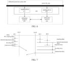
- FIG. 6 illustrates a schematic diagram of a differential protection system for power lines provided by embodiments of the present disclosure.
- a differential protection system 600 is used to protect power line 610.
- the differential protection system 600 may include sampling devices 621 and 622, a differential protector 631, and a differential protector 632.
- the sampling devices 621 and 622 are connected to the power line 610.
- the sampling devices 621 and 622 are configured to obtain sampled currents from the power line 610 and to process the sampled currents.
- the differential protector 630 is connected to the sampling device 621 and is configured to receive first sampled current data transmitted by the sampling device 621.
- the differential protector 632 is connected to the sampling device 622 and is configured to receive second sampled current data transmitted by the sampling device 622.
- the differential protector 631 and the differential protector 632 may both be the differential protectors in the above embodiment.
- the sampling devices 621 and 622 may be merging units.
- Both differential protectors 631 and 632 may perform the data alignment method described in the method embodiment above, thereby enabling compensation of delays caused by the sampling devices and effective alignment of the sampled current data and normal protection of the power line from misoperation when time synchronization is lost.
- the above embodiment of the present disclosure illustrates the data alignment method when there is a delay in the obtaining and processing of current data by taking the merging unit and the process bus as examples.
- Various delay situations in the process bus scenario are further described below.
- FIG. 7 is a timing schematic diagram of a process bus scenario provided in at least one embodiment of the present disclosure.
- current sampling is performed by merging units MU1, MU2, and MU3.
- MU1, MU2, and MU3 sample currents from power lines at different locations.
- MU1, MU2, and MU3 use PPS from GPS to realize synchronized sampling.
- the power lines at different locations can be different locations of a power line or different power lines.
- the differential protector A is used at end A and the differential protector B is used at end B.
- MU1 is connected to the differential protector A through network
- MU2 and MU3 are connected to the differential protector B through network.
- the differential protector B receives data from MU2 and MU3, and the differential protector B will firstly perform data alignment on the data from MU2 and MU3.
- the differential protector A and the differential protector B obtain the sampled current data from MU1 and MU2 (represented by MU2 for MU2 and MU3), respectively.
- the differential protector A there are MU1 sampling delay, network transmission delay, decoding delay for the differential protector A to decode data transmitted from MU1, and transmission delay due to transmission of data by the differential protector A from the time MU1 performs current sampling to the time the differential protector A transmits the sampled current data from that sampling to the differential protector B.
- differential protector B there are MU sampling delays for MU2 and MU3, network transmission delay, alignment delay, decoding delay for the differential protector B to decode data transmitted from MU2, and transmission delay due to transmission of data by the differential protector B.
- the sampling delays of MU1, MU2 and MU3 and the network transmission delays are not controllable by the differential protector A and the differential protector B, while the decoding delays and the transmission delays are relatively stable and can be regarded as fixed values for the differential protector A and the differential protector B.
- the alignment delay is due to the presence of more than one MU at end B. Multiple MUs need to firstly combine multiple sampled currents into one sampled current, e.g., by vector summation.
- embodiments of the present disclosure include a computer program product comprising a computer program, the computer program comprises program codes for performing the method of the above-described process.
Landscapes
- Engineering & Computer Science (AREA)
- Power Engineering (AREA)
- Physics & Mathematics (AREA)
- Theoretical Computer Science (AREA)
- Electromagnetism (AREA)
- General Engineering & Computer Science (AREA)
- General Physics & Mathematics (AREA)
- Emergency Protection Circuit Devices (AREA)
Claims (10)
- Datenausrichtungsverfahren für eine erste Differentialschutzeinrichtung (630), umfassend:Erhalten von ersten abgetasteten Stromdaten von einer ersten Abtastvorrichtung (621) an einem ersten Zeitknoten tA;Übertragen einer ersten Nachricht an eine zweite Differentialschutzeinrichtung (630) nach einer ersten Übertragungsverarbeitungsverzögerung ta, wobei die erste Nachricht die ersten abgetasteten Stromdaten umfasst;Empfangen einer zweiten Nachricht von der zweiten Differentialschutzeinrichtung zu einem ersten Zeitpunkt tA*, wobei die zweite Nachricht zweite abgetastete Stromdaten und ihren Abtastzeitstempel, erste Zeitinformationen der zweiten Differentialschutzeinrichtung in Bezug auf eine Differenz der Empfangszeit tc vom Empfang der ersten Nachricht bis zu einem zweiten Zeitknoten und zweite Zeitinformationen der zweiten Differentialschutzeinrichtung in Bezug auf eine zweite Übertragungsverarbeitungsverzögerung td vom zweiten Zeitknoten bis zur Übertragung der zweiten Nachricht umfasst, wobei der zweite Zeitknoten ein Zeitpunkt ist, zu dem eine zweite Abtastvorrichtung (622) die zweiten abgetasteten Stromdaten erhält;wobei das Verfahren gekennzeichnet ist durch die Schritte:wenn die erste Differentialschutzeinrichtung in Zeitsynchronisation mit der zweiten Differentialschutzeinrichtung ist,Bestimmen eines dritten Zeitknotens, an dem die erste Differentialschutzeinrichtung dritte abgetastete Stromdaten erhält, die dem Abtastzeitstempel der zweiten abgetasteten Stromdaten von der ersten Abtastvorrichtung entsprechen, gemäß dem Abtastzeitstempel, undBerechnen eines ersten berechneten Werts des zweiten Zeitknotens, an dem die zweite Differentialschutzeinrichtung die zweiten abgetasteten Stromdaten von der zweiten Abtastvorrichtung erhält, gemäß dem ersten Zeitknoten tA, dem ersten Zeitpunkt tA*, der ersten Übertragungsverarbeitungsverzögerung ta, der Differenz der Empfangszeit tc und der zweiten Übertragungsverarbeitungsverzögerung td, und Berechnen und Speichern einer Zeitberechnungsabweichung tmem zwischen dem dritten Zeitknoten und dem ersten berechneten Wert des zweiten Zeitknotens;wenn die erste Differentialschutzeinrichtung die Zeitsynchronisation mit der zweiten Differentialschutzeinrichtung verliert,Berechnen eines zweiten berechneten Werts des zweiten Zeitknotens gemäß dem ersten Zeitknoten tA, dem ersten Zeitpunkt tA*, der ersten Übertragungsverarbeitungsverzögerung ta, der Differenz der Empfangszeit tc und der zweiten Übertragungsverarbeitungsverzögerung td, undBestimmen des dritten Zeitknotens gemäß dem zweiten berechneten Wert des zweiten Zeitknotens und der gespeicherten Zeitberechnungsabweichung tmem.
- Datenausrichtungsverfahren nach Anspruch 1, wobei das Berechnen des ersten berechneten Werts des zweiten Zeitknotens, an dem die zweite Differentialschutzeinrichtung die zweiten abgetasteten Stromdaten von der zweiten Abtastvorrichtung erhält, umfasst:Berechnen eines berechneten Werts tp einer Übertragungsverzögerung der Datenübertragung zwischen der ersten Differentialschutzeinrichtung und der zweiten Differentialschutzeinrichtung unter Verwendung des ersten Zeitknotens tA, des ersten Zeitpunkts tA*, der ersten Übertragungsverarbeitungsverzögerung ta, der Differenz der Empfangszeit tc und der zweiten Übertragungsverarbeitungsverzögerung td; undBerechnen des ersten berechneten Werts unter Verwendung des ersten Zeitpunkts tA*, der zweiten Übertragungsverarbeitungsverzögerung td und des berechneten Werts tp der Übertragungsverzögerung; wobei der berechnete Wert tp der Übertragungsverzögerung unter Verwendung der folgenden Formel berechnet wird:


- Datenausrichtungsverfahren nach Anspruch 1, wobei das Berechnen des zweiten berechneten Werts des zweiten Zeitknotens gemäß dem ersten Zeitknoten tA, dem ersten Zeitpunkt tA*, der ersten Übertragungsverarbeitungsverzögerung ta, der Differenz der Empfangszeit tc und der zweiten Übertragungsverarbeitungsverzögerung td umfasst:Berechnen eines berechneten Werts tp einer Übertragungsverzögerung der Datenübertragung zwischen der ersten Differentialschutzeinrichtung und der zweiten Differentialschutzeinrichtung unter Verwendung der folgenden Formel:
 Berechnen des zweiten berechneten Werts tB" unter Verwendung der folgenden Formel:
- Datenausrichtungsverfahren nach einem der Ansprüche 1 bis 3, wobei das Bestimmen des dritten Zeitknotens gemäß dem zweiten berechneten Wert des zweiten Zeitknotens und der gespeicherten Zeitberechnungsabweichung tmem umfasst:Berechnen eines geschätzten Werts des dritten Zeitknotens aus der Summe des zweiten berechneten Werts und der Zeitberechnungsabweichung tmem und Nehmen, als den dritten Zeitknoten, eines Zeitknotens, der dem geschätzten Wert des dritten Zeitknotens am nächsten ist, unter einer Vielzahl von Zeitknoten, an denen die erste Differentialschutzeinrichtung abgetastete Stromdaten von der ersten Abtastvorrichtung erhält;wobei der geschätzte Wert tA' des dritten Zeitknotens unter Verwendung der folgenden Formel berechnet wird:

- Datenausrichtungsverfahren nach einem der Ansprüche 1 bis 3, wobei, wenn die erste Differentialschutzeinrichtung in Zeitsynchronisation mit der zweiten Differentialschutzeinrichtung ist, das Verfahren ferner umfasst:
Berechnen und Speichern der Zeitberechnungsabweichung tmem, wann immer ein Zeitsynchronisationssignal empfangen wird, oder Berechnen und Speichern der Zeitberechnungsabweichung tmem, wann immer die abgetasteten Stromdaten von der ersten Abtastvorrichtung empfangen werden. - Datenausrichtungsverfahren nach einem der Ansprüche 1 bis 3, wobei die zweite Nachricht ferner anzeigt, dass die zweite Differentialschutzeinrichtung die Zeitsynchronisation verliert oder die Zeitsynchronisation wiedergewinnt.
- Datenausrichtungsverfahren nach einem der Ansprüche 1 bis 3, wobei die erste Abtastvorrichtung eine erste Zusammenführungseinheit ist und die zweite Abtastvorrichtung eine zweite Zusammenführungseinheit ist, wobei die erste Zusammenführungseinheit und die zweite Zusammenführungseinheit jeweils abgetastete Stromwerte von verschiedenen Orten derselben Stromleitung erhalten.
- Datenausrichtungsverfahren nach einem der Ansprüche 1 bis 3, wobei die erste Differentialschutzeinrichtung und die zweite Differentialschutzeinrichtung die Satellitenzeitsteuerung verwenden, um die Zeitsynchronisation aufrechtzuerhalten.
- Differentialschutzeinrichtung, umfassend einen Prozessor und einen Speicher mit darauf gespeicherten Programmcodes, wobei die Programmcodes, wenn sie von dem Prozessor ausgeführt werden, das Datenausrichtungsverfahren nach einem der Ansprüche 1 bis 8 durchführen.
- Differentialschutzsystem für eine Stromleitung, umfassend:eine erste Abtastvorrichtung und eine zweite Abtastvorrichtung, die konfiguriert sind, um jeweils abgetastete Stromwerte von verschiedenen Orten an der Stromleitung zu erhalten;eine erste Differentialschutzeinrichtung, die mit der ersten Abtastvorrichtung verbunden ist und konfiguriert ist, um erste abgetastete Stromdaten zu empfangen, die von der ersten Abtastvorrichtung übertragen werden; undeine zweite Differentialschutzeinrichtung, die mit der zweiten Abtastvorrichtung verbunden ist und konfiguriert ist, um zweite abgetastete Stromdaten zu empfangen, die von der zweiten Abtastvorrichtung übertragen werden,wobei die erste Differentialschutzeinrichtung und die zweite Differentialschutzeinrichtung jeweils die Differentialschutzeinrichtung nach Anspruch 9 sind.
Applications Claiming Priority (1)
| Application Number | Priority Date | Filing Date | Title |
|---|---|---|---|
| CN202210113635.7A CN116560456A (zh) | 2022-01-30 | 2022-01-30 | 数据对齐方法、差动保护器以及差动保护系统 |
Publications (4)
| Publication Number | Publication Date |
|---|---|
| EP4231472A2 EP4231472A2 (de) | 2023-08-23 |
| EP4231472A3 EP4231472A3 (de) | 2023-09-13 |
| EP4231472C0 EP4231472C0 (de) | 2025-01-15 |
| EP4231472B1 true EP4231472B1 (de) | 2025-01-15 |
Family
ID=85278423
Family Applications (1)
| Application Number | Title | Priority Date | Filing Date |
|---|---|---|---|
| EP23305083.0A Active EP4231472B1 (de) | 2022-01-30 | 2023-01-24 | Datenausrichtungsverfahren, differenzialschutz und differenzialschutzsystem |
Country Status (3)
| Country | Link |
|---|---|
| US (1) | US12062903B2 (de) |
| EP (1) | EP4231472B1 (de) |
| CN (1) | CN116560456A (de) |
Families Citing this family (2)
| Publication number | Priority date | Publication date | Assignee | Title |
|---|---|---|---|---|
| CN116866157B (zh) * | 2023-09-05 | 2023-11-14 | 珠海菲森电力科技有限公司 | 一种基于5g纵联差动保护的数据传输方法 |
| CN119994805A (zh) * | 2023-11-10 | 2025-05-13 | 施耐德电气工业公司 | 用于差动保护装置的采样同步方法、差动保护装置和系统 |
Family Cites Families (9)
| Publication number | Priority date | Publication date | Assignee | Title |
|---|---|---|---|---|
| GB8509422D0 (en) * | 1985-04-12 | 1985-05-15 | Gen Electric Co Plc | Relays |
| WO2009000304A1 (de) * | 2007-06-27 | 2008-12-31 | Siemens Aktiengesellschaft | Verfahren zum erhöhen der empfindlichkeit eines differentialschutzsystems |
| WO2009012809A1 (en) * | 2007-07-23 | 2009-01-29 | Abb Technology Ag | Method and protection device for a power network accounting for route switching in a telecommunication network |
| JP2010279235A (ja) * | 2009-06-01 | 2010-12-09 | Mitsubishi Electric Corp | 電流差動リレー |
| US8154836B2 (en) * | 2009-09-17 | 2012-04-10 | Schweitzer Engineering Laboratories, Inc. | Line current differential protection upon loss of an external time reference |
| WO2015063815A1 (ja) * | 2013-10-31 | 2015-05-07 | 三菱電機株式会社 | 信号処理装置 |
| US9602271B2 (en) * | 2015-06-01 | 2017-03-21 | Globalfoundries Inc. | Sub-nanosecond distributed clock synchronization using alignment marker in ethernet IEEE 1588 protocol |
| CN112421566B (zh) * | 2020-11-10 | 2022-06-17 | 北京博阳慧源电力科技有限公司 | 一种基于以太网精密时间协议的纵联差动保护方法 |
| US11949222B2 (en) * | 2021-01-26 | 2024-04-02 | Schweitzer Engineering Laboratories, Inc. | Sample time offset alignment of electric power system samples independent of a common time source |
-
2022
- 2022-01-30 CN CN202210113635.7A patent/CN116560456A/zh active Pending
-
2023
- 2023-01-23 US US18/099,999 patent/US12062903B2/en active Active
- 2023-01-24 EP EP23305083.0A patent/EP4231472B1/de active Active
Also Published As
| Publication number | Publication date |
|---|---|
| EP4231472A3 (de) | 2023-09-13 |
| US12062903B2 (en) | 2024-08-13 |
| EP4231472C0 (de) | 2025-01-15 |
| US20230246438A1 (en) | 2023-08-03 |
| EP4231472A2 (de) | 2023-08-23 |
| CN116560456A (zh) | 2023-08-08 |
Similar Documents
| Publication | Publication Date | Title |
|---|---|---|
| EP4231472B1 (de) | Datenausrichtungsverfahren, differenzialschutz und differenzialschutzsystem | |
| EP2728693B1 (de) | Stromdifferenzialschutz | |
| US8953645B2 (en) | Communication system, communication apparatus and time synchronization method | |
| EP3016306B1 (de) | Verfahren und vorrichtung zur bereitstellung von zeitsynchronisierung von fahrzeuginternem netzwerk mittels redundantem grandmaster | |
| US20100138187A1 (en) | Estimating a time offset between stationary clocks | |
| US10901372B2 (en) | Time synchronization device, time synchronization system, and time synchronization method | |
| EP2320602B1 (de) | Vorrichtung zur festlegung einer laufzeit | |
| US20010023464A1 (en) | Time synchronization of units in a system | |
| JP2010041899A (ja) | 保護リレーシステム | |
| EP2458772A2 (de) | Verfahren und System zur Netzwerksynchronisierung durch Benutzung bestehender Netzwerkkabel | |
| US6940935B2 (en) | System and method for aligning data between local and remote sources thereof | |
| CN106850397A (zh) | 物联网中消息传递方法和装置 | |
| CN113835079B (zh) | 一种车载激光雷达系统、数据处理方法、装置及存储介质 | |
| KR20080110670A (ko) | 보호 릴레이 장치, 보호 릴레이 장치의 제어 방법 및 제어 프로그램을 기록한 기록 매체 | |
| JP2001324584A (ja) | 時刻同期装置、時刻同期システム及び時刻同期装置の制御方法 | |
| EP3876442A2 (de) | Zeitsynchronisierung von verteiltem netzwerk | |
| EP3637640B1 (de) | Zeitsynchronisationsverfahren und -vorrichtung | |
| JP2692907B2 (ja) | サンプリング時刻同期方式 | |
| JP5844022B1 (ja) | プロセスバス適用保護システム | |
| EP4199384A1 (de) | Verfahren und vorrichtung zur bestimmung eines taktfrequenzversatzes | |
| JPH10191473A (ja) | 監視制御システム | |
| CN116566530B (zh) | 差动保护装置的对时方法、差动保护装置和差动保护系统 | |
| JP2006309513A (ja) | 電話端末、電話端末管理装置及び電話通信システム | |
| KR20180054103A (ko) | 비정상 동작 상황을 개선한 gps를 이용하는 장치의 utc 시간 동기 방법 | |
| CN113676280B (zh) | 一种基于Modbus协议的多设备时钟同步方法 |
Legal Events
| Date | Code | Title | Description |
|---|---|---|---|
| PUAI | Public reference made under article 153(3) epc to a published international application that has entered the european phase |
Free format text: ORIGINAL CODE: 0009012 |
|
| STAA | Information on the status of an ep patent application or granted ep patent |
Free format text: STATUS: THE APPLICATION HAS BEEN PUBLISHED |
|
| PUAL | Search report despatched |
Free format text: ORIGINAL CODE: 0009013 |
|
| AK | Designated contracting states |
Kind code of ref document: A2 Designated state(s): AL AT BE BG CH CY CZ DE DK EE ES FI FR GB GR HR HU IE IS IT LI LT LU LV MC ME MK MT NL NO PL PT RO RS SE SI SK SM TR |
|
| AK | Designated contracting states |
Kind code of ref document: A3 Designated state(s): AL AT BE BG CH CY CZ DE DK EE ES FI FR GB GR HR HU IE IS IT LI LT LU LV MC ME MK MT NL NO PL PT RO RS SE SI SK SM TR |
|
| RIC1 | Information provided on ipc code assigned before grant |
Ipc: H02H 7/26 20060101ALI20230804BHEP Ipc: H02H 1/00 20060101ALI20230804BHEP Ipc: H02H 3/28 20060101AFI20230804BHEP |
|
| STAA | Information on the status of an ep patent application or granted ep patent |
Free format text: STATUS: REQUEST FOR EXAMINATION WAS MADE |
|
| 17P | Request for examination filed |
Effective date: 20240223 |
|
| RBV | Designated contracting states (corrected) |
Designated state(s): AL AT BE BG CH CY CZ DE DK EE ES FI FR GB GR HR HU IE IS IT LI LT LU LV MC ME MK MT NL NO PL PT RO RS SE SI SK SM TR |
|
| GRAP | Despatch of communication of intention to grant a patent |
Free format text: ORIGINAL CODE: EPIDOSNIGR1 |
|
| STAA | Information on the status of an ep patent application or granted ep patent |
Free format text: STATUS: GRANT OF PATENT IS INTENDED |
|
| INTG | Intention to grant announced |
Effective date: 20240820 |
|
| GRAS | Grant fee paid |
Free format text: ORIGINAL CODE: EPIDOSNIGR3 |
|
| GRAA | (expected) grant |
Free format text: ORIGINAL CODE: 0009210 |
|
| STAA | Information on the status of an ep patent application or granted ep patent |
Free format text: STATUS: THE PATENT HAS BEEN GRANTED |
|
| AK | Designated contracting states |
Kind code of ref document: B1 Designated state(s): AL AT BE BG CH CY CZ DE DK EE ES FI FR GB GR HR HU IE IS IT LI LT LU LV MC ME MK MT NL NO PL PT RO RS SE SI SK SM TR |
|
| REG | Reference to a national code |
Ref country code: CH Ref legal event code: EP Ref country code: GB Ref legal event code: FG4D |
|
| REG | Reference to a national code |
Ref country code: DE Ref legal event code: R096 Ref document number: 602023001693 Country of ref document: DE |
|
| REG | Reference to a national code |
Ref country code: IE Ref legal event code: FG4D |
|
| U01 | Request for unitary effect filed |
Effective date: 20250115 |
|
| U07 | Unitary effect registered |
Designated state(s): AT BE BG DE DK EE FI FR IT LT LU LV MT NL PT RO SE SI Effective date: 20250121 |
|
| U20 | Renewal fee for the european patent with unitary effect paid |
Year of fee payment: 3 Effective date: 20250127 |
|
| PG25 | Lapsed in a contracting state [announced via postgrant information from national office to epo] |
Ref country code: RS Free format text: LAPSE BECAUSE OF FAILURE TO SUBMIT A TRANSLATION OF THE DESCRIPTION OR TO PAY THE FEE WITHIN THE PRESCRIBED TIME-LIMIT Effective date: 20250415 |
|
| PG25 | Lapsed in a contracting state [announced via postgrant information from national office to epo] |
Ref country code: PL Free format text: LAPSE BECAUSE OF FAILURE TO SUBMIT A TRANSLATION OF THE DESCRIPTION OR TO PAY THE FEE WITHIN THE PRESCRIBED TIME-LIMIT Effective date: 20250115 |
|
| PG25 | Lapsed in a contracting state [announced via postgrant information from national office to epo] |
Ref country code: ES Free format text: LAPSE BECAUSE OF FAILURE TO SUBMIT A TRANSLATION OF THE DESCRIPTION OR TO PAY THE FEE WITHIN THE PRESCRIBED TIME-LIMIT Effective date: 20250115 |
|
| PG25 | Lapsed in a contracting state [announced via postgrant information from national office to epo] |
Ref country code: NO Free format text: LAPSE BECAUSE OF FAILURE TO SUBMIT A TRANSLATION OF THE DESCRIPTION OR TO PAY THE FEE WITHIN THE PRESCRIBED TIME-LIMIT Effective date: 20250415 Ref country code: IS Free format text: LAPSE BECAUSE OF FAILURE TO SUBMIT A TRANSLATION OF THE DESCRIPTION OR TO PAY THE FEE WITHIN THE PRESCRIBED TIME-LIMIT Effective date: 20250515 |
|
| PG25 | Lapsed in a contracting state [announced via postgrant information from national office to epo] |
Ref country code: HR Free format text: LAPSE BECAUSE OF FAILURE TO SUBMIT A TRANSLATION OF THE DESCRIPTION OR TO PAY THE FEE WITHIN THE PRESCRIBED TIME-LIMIT Effective date: 20250115 |
|
| PG25 | Lapsed in a contracting state [announced via postgrant information from national office to epo] |
Ref country code: GR Free format text: LAPSE BECAUSE OF FAILURE TO SUBMIT A TRANSLATION OF THE DESCRIPTION OR TO PAY THE FEE WITHIN THE PRESCRIBED TIME-LIMIT Effective date: 20250416 |
|
| PG25 | Lapsed in a contracting state [announced via postgrant information from national office to epo] |
Ref country code: SM Free format text: LAPSE BECAUSE OF FAILURE TO SUBMIT A TRANSLATION OF THE DESCRIPTION OR TO PAY THE FEE WITHIN THE PRESCRIBED TIME-LIMIT Effective date: 20250115 |
|
| PG25 | Lapsed in a contracting state [announced via postgrant information from national office to epo] |
Ref country code: MC Free format text: LAPSE BECAUSE OF FAILURE TO SUBMIT A TRANSLATION OF THE DESCRIPTION OR TO PAY THE FEE WITHIN THE PRESCRIBED TIME-LIMIT Effective date: 20250115 |
|
| PG25 | Lapsed in a contracting state [announced via postgrant information from national office to epo] |
Ref country code: CZ Free format text: LAPSE BECAUSE OF FAILURE TO SUBMIT A TRANSLATION OF THE DESCRIPTION OR TO PAY THE FEE WITHIN THE PRESCRIBED TIME-LIMIT Effective date: 20250115 |
|
| PG25 | Lapsed in a contracting state [announced via postgrant information from national office to epo] |
Ref country code: SK Free format text: LAPSE BECAUSE OF FAILURE TO SUBMIT A TRANSLATION OF THE DESCRIPTION OR TO PAY THE FEE WITHIN THE PRESCRIBED TIME-LIMIT Effective date: 20250115 |
|
| PLBE | No opposition filed within time limit |
Free format text: ORIGINAL CODE: 0009261 |
|
| STAA | Information on the status of an ep patent application or granted ep patent |
Free format text: STATUS: NO OPPOSITION FILED WITHIN TIME LIMIT |
|
| 26N | No opposition filed |
Effective date: 20251016 |
|
| PG25 | Lapsed in a contracting state [announced via postgrant information from national office to epo] |
Ref country code: IE Free format text: LAPSE BECAUSE OF NON-PAYMENT OF DUE FEES Effective date: 20250124 |
|
| U20 | Renewal fee for the european patent with unitary effect paid |
Year of fee payment: 4 Effective date: 20260126 |