EP4231410A1 - Battery management system and power supply device - Google Patents
Battery management system and power supply device Download PDFInfo
- Publication number
- EP4231410A1 EP4231410A1 EP22785676.2A EP22785676A EP4231410A1 EP 4231410 A1 EP4231410 A1 EP 4231410A1 EP 22785676 A EP22785676 A EP 22785676A EP 4231410 A1 EP4231410 A1 EP 4231410A1
- Authority
- EP
- European Patent Office
- Prior art keywords
- battery management
- management module
- code data
- channel
- battery
- Prior art date
- Legal status (The legal status is an assumption and is not a legal conclusion. Google has not performed a legal analysis and makes no representation as to the accuracy of the status listed.)
- Granted
Links
Images


Classifications
-
- G—PHYSICS
- G01—MEASURING; TESTING
- G01R—MEASURING ELECTRIC VARIABLES; MEASURING MAGNETIC VARIABLES
- G01R31/00—Arrangements for testing electric properties; Arrangements for locating electric faults; Arrangements for electrical testing characterised by what is being tested not provided for elsewhere
- G01R31/36—Arrangements for testing, measuring or monitoring the electrical condition of accumulators or electric batteries, e.g. capacity or state of charge [SoC]
- G01R31/396—Acquisition or processing of data for testing or for monitoring individual cells or groups of cells within a battery
-
- B—PERFORMING OPERATIONS; TRANSPORTING
- B60—VEHICLES IN GENERAL
- B60L—PROPULSION OF ELECTRICALLY-PROPELLED VEHICLES; SUPPLYING ELECTRIC POWER FOR AUXILIARY EQUIPMENT OF ELECTRICALLY-PROPELLED VEHICLES; ELECTRODYNAMIC BRAKE SYSTEMS FOR VEHICLES IN GENERAL; MAGNETIC SUSPENSION OR LEVITATION FOR VEHICLES; MONITORING OPERATING VARIABLES OF ELECTRICALLY-PROPELLED VEHICLES; ELECTRIC SAFETY DEVICES FOR ELECTRICALLY-PROPELLED VEHICLES
- B60L3/00—Electric devices on electrically-propelled vehicles for safety purposes; Monitoring operating variables, e.g. speed, deceleration or energy consumption
- B60L3/0023—Detecting, eliminating, remedying or compensating for drive train abnormalities, e.g. failures within the drive train
- B60L3/0084—Detecting, eliminating, remedying or compensating for drive train abnormalities, e.g. failures within the drive train relating to control modules
-
- G—PHYSICS
- G06—COMPUTING OR CALCULATING; COUNTING
- G06F—ELECTRIC DIGITAL DATA PROCESSING
- G06F11/00—Error detection; Error correction; Monitoring
- G06F11/30—Monitoring
- G06F11/3065—Monitoring arrangements determined by the means or processing involved in reporting the monitored data
- G06F11/3072—Monitoring arrangements determined by the means or processing involved in reporting the monitored data where the reporting involves data filtering, e.g. pattern matching, time or event triggered, adaptive or policy-based reporting
- G06F11/3075—Monitoring arrangements determined by the means or processing involved in reporting the monitored data where the reporting involves data filtering, e.g. pattern matching, time or event triggered, adaptive or policy-based reporting the data filtering being achieved in order to maintain consistency among the monitored data, e.g. ensuring that the monitored data belong to the same timeframe, to the same system or component
-
- B—PERFORMING OPERATIONS; TRANSPORTING
- B60—VEHICLES IN GENERAL
- B60L—PROPULSION OF ELECTRICALLY-PROPELLED VEHICLES; SUPPLYING ELECTRIC POWER FOR AUXILIARY EQUIPMENT OF ELECTRICALLY-PROPELLED VEHICLES; ELECTRODYNAMIC BRAKE SYSTEMS FOR VEHICLES IN GENERAL; MAGNETIC SUSPENSION OR LEVITATION FOR VEHICLES; MONITORING OPERATING VARIABLES OF ELECTRICALLY-PROPELLED VEHICLES; ELECTRIC SAFETY DEVICES FOR ELECTRICALLY-PROPELLED VEHICLES
- B60L3/00—Electric devices on electrically-propelled vehicles for safety purposes; Monitoring operating variables, e.g. speed, deceleration or energy consumption
- B60L3/0092—Electric devices on electrically-propelled vehicles for safety purposes; Monitoring operating variables, e.g. speed, deceleration or energy consumption with use of redundant elements for safety purposes
-
- B—PERFORMING OPERATIONS; TRANSPORTING
- B60—VEHICLES IN GENERAL
- B60L—PROPULSION OF ELECTRICALLY-PROPELLED VEHICLES; SUPPLYING ELECTRIC POWER FOR AUXILIARY EQUIPMENT OF ELECTRICALLY-PROPELLED VEHICLES; ELECTRODYNAMIC BRAKE SYSTEMS FOR VEHICLES IN GENERAL; MAGNETIC SUSPENSION OR LEVITATION FOR VEHICLES; MONITORING OPERATING VARIABLES OF ELECTRICALLY-PROPELLED VEHICLES; ELECTRIC SAFETY DEVICES FOR ELECTRICALLY-PROPELLED VEHICLES
- B60L50/00—Electric propulsion with power supplied within the vehicle
- B60L50/50—Electric propulsion with power supplied within the vehicle using propulsion power supplied by batteries or fuel cells
- B60L50/60—Electric propulsion with power supplied within the vehicle using propulsion power supplied by batteries or fuel cells using power supplied by batteries
-
- B—PERFORMING OPERATIONS; TRANSPORTING
- B60—VEHICLES IN GENERAL
- B60L—PROPULSION OF ELECTRICALLY-PROPELLED VEHICLES; SUPPLYING ELECTRIC POWER FOR AUXILIARY EQUIPMENT OF ELECTRICALLY-PROPELLED VEHICLES; ELECTRODYNAMIC BRAKE SYSTEMS FOR VEHICLES IN GENERAL; MAGNETIC SUSPENSION OR LEVITATION FOR VEHICLES; MONITORING OPERATING VARIABLES OF ELECTRICALLY-PROPELLED VEHICLES; ELECTRIC SAFETY DEVICES FOR ELECTRICALLY-PROPELLED VEHICLES
- B60L58/00—Methods or circuit arrangements for monitoring or controlling batteries or fuel cells, specially adapted for electric vehicles
- B60L58/10—Methods or circuit arrangements for monitoring or controlling batteries or fuel cells, specially adapted for electric vehicles for monitoring or controlling batteries
-
- B—PERFORMING OPERATIONS; TRANSPORTING
- B60—VEHICLES IN GENERAL
- B60L—PROPULSION OF ELECTRICALLY-PROPELLED VEHICLES; SUPPLYING ELECTRIC POWER FOR AUXILIARY EQUIPMENT OF ELECTRICALLY-PROPELLED VEHICLES; ELECTRODYNAMIC BRAKE SYSTEMS FOR VEHICLES IN GENERAL; MAGNETIC SUSPENSION OR LEVITATION FOR VEHICLES; MONITORING OPERATING VARIABLES OF ELECTRICALLY-PROPELLED VEHICLES; ELECTRIC SAFETY DEVICES FOR ELECTRICALLY-PROPELLED VEHICLES
- B60L58/00—Methods or circuit arrangements for monitoring or controlling batteries or fuel cells, specially adapted for electric vehicles
- B60L58/10—Methods or circuit arrangements for monitoring or controlling batteries or fuel cells, specially adapted for electric vehicles for monitoring or controlling batteries
- B60L58/18—Methods or circuit arrangements for monitoring or controlling batteries or fuel cells, specially adapted for electric vehicles for monitoring or controlling batteries of two or more battery modules
-
- B—PERFORMING OPERATIONS; TRANSPORTING
- B60—VEHICLES IN GENERAL
- B60L—PROPULSION OF ELECTRICALLY-PROPELLED VEHICLES; SUPPLYING ELECTRIC POWER FOR AUXILIARY EQUIPMENT OF ELECTRICALLY-PROPELLED VEHICLES; ELECTRODYNAMIC BRAKE SYSTEMS FOR VEHICLES IN GENERAL; MAGNETIC SUSPENSION OR LEVITATION FOR VEHICLES; MONITORING OPERATING VARIABLES OF ELECTRICALLY-PROPELLED VEHICLES; ELECTRIC SAFETY DEVICES FOR ELECTRICALLY-PROPELLED VEHICLES
- B60L58/00—Methods or circuit arrangements for monitoring or controlling batteries or fuel cells, specially adapted for electric vehicles
- B60L58/10—Methods or circuit arrangements for monitoring or controlling batteries or fuel cells, specially adapted for electric vehicles for monitoring or controlling batteries
- B60L58/18—Methods or circuit arrangements for monitoring or controlling batteries or fuel cells, specially adapted for electric vehicles for monitoring or controlling batteries of two or more battery modules
- B60L58/21—Methods or circuit arrangements for monitoring or controlling batteries or fuel cells, specially adapted for electric vehicles for monitoring or controlling batteries of two or more battery modules having the same nominal voltage
-
- G—PHYSICS
- G01—MEASURING; TESTING
- G01R—MEASURING ELECTRIC VARIABLES; MEASURING MAGNETIC VARIABLES
- G01R31/00—Arrangements for testing electric properties; Arrangements for locating electric faults; Arrangements for electrical testing characterised by what is being tested not provided for elsewhere
- G01R31/36—Arrangements for testing, measuring or monitoring the electrical condition of accumulators or electric batteries, e.g. capacity or state of charge [SoC]
- G01R31/367—Software therefor, e.g. for battery testing using modelling or look-up tables
-
- G—PHYSICS
- G06—COMPUTING OR CALCULATING; COUNTING
- G06F—ELECTRIC DIGITAL DATA PROCESSING
- G06F11/00—Error detection; Error correction; Monitoring
- G06F11/30—Monitoring
- G06F11/32—Monitoring with visual or acoustical indication of the functioning of the machine
- G06F11/324—Display of status information
- G06F11/327—Alarm or error message display
-
- G—PHYSICS
- G06—COMPUTING OR CALCULATING; COUNTING
- G06F—ELECTRIC DIGITAL DATA PROCESSING
- G06F21/00—Security arrangements for protecting computers, components thereof, programs or data against unauthorised activity
- G06F21/30—Authentication, i.e. establishing the identity or authorisation of security principals
- G06F21/45—Structures or tools for the administration of authentication
-
- G—PHYSICS
- G06—COMPUTING OR CALCULATING; COUNTING
- G06F—ELECTRIC DIGITAL DATA PROCESSING
- G06F8/00—Arrangements for software engineering
- G06F8/30—Creation or generation of source code
- G06F8/31—Programming languages or programming paradigms
-
- H—ELECTRICITY
- H01—ELECTRIC ELEMENTS
- H01M—PROCESSES OR MEANS, e.g. BATTERIES, FOR THE DIRECT CONVERSION OF CHEMICAL ENERGY INTO ELECTRICAL ENERGY
- H01M10/00—Secondary cells; Manufacture thereof
- H01M10/42—Methods or arrangements for servicing or maintenance of secondary cells or secondary half-cells
-
- H—ELECTRICITY
- H01—ELECTRIC ELEMENTS
- H01M—PROCESSES OR MEANS, e.g. BATTERIES, FOR THE DIRECT CONVERSION OF CHEMICAL ENERGY INTO ELECTRICAL ENERGY
- H01M10/00—Secondary cells; Manufacture thereof
- H01M10/42—Methods or arrangements for servicing or maintenance of secondary cells or secondary half-cells
- H01M10/425—Structural combination with electronic components, e.g. electronic circuits integrated to the outside of the casing
-
- H—ELECTRICITY
- H01—ELECTRIC ELEMENTS
- H01M—PROCESSES OR MEANS, e.g. BATTERIES, FOR THE DIRECT CONVERSION OF CHEMICAL ENERGY INTO ELECTRICAL ENERGY
- H01M10/00—Secondary cells; Manufacture thereof
- H01M10/42—Methods or arrangements for servicing or maintenance of secondary cells or secondary half-cells
- H01M10/48—Accumulators combined with arrangements for measuring, testing or indicating the condition of cells, e.g. the level or density of the electrolyte
- H01M10/482—Accumulators combined with arrangements for measuring, testing or indicating the condition of cells, e.g. the level or density of the electrolyte for several batteries or cells simultaneously or sequentially
-
- H—ELECTRICITY
- H02—GENERATION; CONVERSION OR DISTRIBUTION OF ELECTRIC POWER
- H02J—ELECTRIC POWER NETWORKS; CIRCUIT ARRANGEMENTS OR SYSTEMS FOR SUPPLYING OR DISTRIBUTING ELECTRIC POWER; SYSTEMS FOR STORING ELECTRIC ENERGY
- H02J7/00—Circuit arrangements for charging or discharging batteries or for supplying loads from batteries
-
- H—ELECTRICITY
- H02—GENERATION; CONVERSION OR DISTRIBUTION OF ELECTRIC POWER
- H02J—ELECTRIC POWER NETWORKS; CIRCUIT ARRANGEMENTS OR SYSTEMS FOR SUPPLYING OR DISTRIBUTING ELECTRIC POWER; SYSTEMS FOR STORING ELECTRIC ENERGY
- H02J7/00—Circuit arrangements for charging or discharging batteries or for supplying loads from batteries
- H02J7/34—Parallel operation in networks using both storage and other DC sources, e.g. providing buffering
-
- H—ELECTRICITY
- H02—GENERATION; CONVERSION OR DISTRIBUTION OF ELECTRIC POWER
- H02J—ELECTRIC POWER NETWORKS; CIRCUIT ARRANGEMENTS OR SYSTEMS FOR SUPPLYING OR DISTRIBUTING ELECTRIC POWER; SYSTEMS FOR STORING ELECTRIC ENERGY
- H02J7/00—Circuit arrangements for charging or discharging batteries or for supplying loads from batteries
- H02J7/40—Circuit arrangements for charging or discharging batteries or for supplying loads from batteries characterised by the exchange of charge or discharge related data
- H02J7/47—Arrangements for checking compatibility or authentication between one component, e.g. a battery or a battery charger, and another component, e.g. a power source
-
- H—ELECTRICITY
- H02—GENERATION; CONVERSION OR DISTRIBUTION OF ELECTRIC POWER
- H02J—ELECTRIC POWER NETWORKS; CIRCUIT ARRANGEMENTS OR SYSTEMS FOR SUPPLYING OR DISTRIBUTING ELECTRIC POWER; SYSTEMS FOR STORING ELECTRIC ENERGY
- H02J7/00—Circuit arrangements for charging or discharging batteries or for supplying loads from batteries
- H02J7/50—Circuit arrangements for charging or discharging batteries or for supplying loads from batteries acting upon multiple batteries simultaneously or sequentially
-
- H—ELECTRICITY
- H01—ELECTRIC ELEMENTS
- H01M—PROCESSES OR MEANS, e.g. BATTERIES, FOR THE DIRECT CONVERSION OF CHEMICAL ENERGY INTO ELECTRICAL ENERGY
- H01M10/00—Secondary cells; Manufacture thereof
- H01M10/42—Methods or arrangements for servicing or maintenance of secondary cells or secondary half-cells
- H01M10/425—Structural combination with electronic components, e.g. electronic circuits integrated to the outside of the casing
- H01M2010/4271—Battery management systems including electronic circuits, e.g. control of current or voltage to keep battery in healthy state, cell balancing
-
- H—ELECTRICITY
- H01—ELECTRIC ELEMENTS
- H01M—PROCESSES OR MEANS, e.g. BATTERIES, FOR THE DIRECT CONVERSION OF CHEMICAL ENERGY INTO ELECTRICAL ENERGY
- H01M10/00—Secondary cells; Manufacture thereof
- H01M10/42—Methods or arrangements for servicing or maintenance of secondary cells or secondary half-cells
- H01M10/425—Structural combination with electronic components, e.g. electronic circuits integrated to the outside of the casing
- H01M2010/4278—Systems for data transfer from batteries, e.g. transfer of battery parameters to a controller, data transferred between battery controller and main controller
-
- H—ELECTRICITY
- H04—ELECTRIC COMMUNICATION TECHNIQUE
- H04L—TRANSMISSION OF DIGITAL INFORMATION, e.g. TELEGRAPHIC COMMUNICATION
- H04L12/00—Data switching networks
- H04L12/28—Data switching networks characterised by path configuration, e.g. LAN [Local Area Networks] or WAN [Wide Area Networks]
- H04L12/40—Bus networks
- H04L2012/40208—Bus networks characterized by the use of a particular bus standard
- H04L2012/40215—Controller Area Network CAN
-
- Y—GENERAL TAGGING OF NEW TECHNOLOGICAL DEVELOPMENTS; GENERAL TAGGING OF CROSS-SECTIONAL TECHNOLOGIES SPANNING OVER SEVERAL SECTIONS OF THE IPC; TECHNICAL SUBJECTS COVERED BY FORMER USPC CROSS-REFERENCE ART COLLECTIONS [XRACs] AND DIGESTS
- Y02—TECHNOLOGIES OR APPLICATIONS FOR MITIGATION OR ADAPTATION AGAINST CLIMATE CHANGE
- Y02E—REDUCTION OF GREENHOUSE GAS [GHG] EMISSIONS, RELATED TO ENERGY GENERATION, TRANSMISSION OR DISTRIBUTION
- Y02E60/00—Enabling technologies; Technologies with a potential or indirect contribution to GHG emissions mitigation
- Y02E60/10—Energy storage using batteries
Definitions
- This application relates to the field of battery technologies, and in particular, to a battery management system and a power supply device.
- a battery management system (Battery Management System, BMS) mainly manages secondary batteries, with an aim to improve utilization of batteries and prevent battery over-charging and over-discharging, thus extending service life and monitoring states of the batteries.
- BMS Battery Management System
- a master control unit transmits a coding signal to a slave control unit. After receiving the coding signal, the slave control unit performs coding and transmits a current code and a coding signal to a next slave control unit. After all slave control units finish coding, a coding complete flag and a current code count are returned to the master control unit. If failure occurs in any slave control unit during the coding, all subsequent slave control units are unable to continue coding, resulting in low management reliability.
- a battery management system includes:
- the code detection circuit is disposed in the second battery management module, the first battery management module determines code data based on voltage of at least one sampling channel in the plurality of sampling channels, and then the first battery management module performs identity authentication based on the code data of the second battery management module and obtains an authentication result.
- the code detection circuit is disposed in the second battery management module, and code data is determined based on voltage of the sampling channel in the code detection circuit, so that failure in any battery management module does not affect code data collection by other battery management modules, thus achieving a high management reliability.
- the first battery management module is further configured to detect, based on a predefined range, whether the code data of the second battery management module is correct, and output fault prompt information when incorrect code data is detected. Fault prompt information is outputted when incorrect code data is detected, facilitating timely troubleshooting.
- the first battery management module is further configured to determine whether a quantity of received code data is consistent with a preset value, and output fault prompt information when the quantity of the received code data is inconsistent with the preset value. Fault prompt information is outputted when the quantity of the received code data is inconsistent with the preset value, further facilitating timely troubleshooting.
- the sampling channels of the code detection circuit include a setting channel and an adjustment channel, where the setting channel is configured to be connected to a power terminal or grounded, and the adjustment channel is configured to be connected to the setting channel through a harness or be connected to the setting channel through a voltage divider resistor.
- the setting channel of the code detection circuit is connected to the power terminal or grounded, the adjustment channel is connected to the setting channel through the harness or voltage divider resistor, and the voltages of the channels are set in such a way that voltages of some channels are fixed and voltages of the remaining channels are adjustable, so that code information of the battery management modules is adjustable.
- the second battery management module further includes a battery management unit (Battery Management Unit, BMU for short) low-voltage connector, where the BMU low-voltage connector is connected to a corresponding sampling channel of the code detection circuit.
- BMU Battery Management Unit
- the BMU low-voltage connector is connected to the corresponding sampling channel of the code detection circuit, facilitating voltage setting for channels with voltage unconfigured.
- the BMU low-voltage connector is further connected to an external low-voltage connector.
- the channel with voltage unconfigured is connected to the channel with voltage configured through the external low-voltage connector to perform code configuration for the battery management modules. This can also reduce sizes of the battery management modules.
- the first battery management module and the second battery management module perform serial communication.
- the first battery management module and the second battery management module perform serial communication, facilitating code data transmission and collection between the battery management modules.
- the first battery management module and the second battery management module perform serial communication through a controller area network (Controller Area Network, CAN for short) interface, allowing for real-time data communication.
- controller area network Controller Area Network, CAN for short
- a power supply device includes a battery pack and the foregoing battery management system.
- a code detection circuit is disposed in a second battery management module, a first battery management module determines code data based on voltage of at least one sampling channel in a plurality of sampling channels, and then the first battery management module performs identity authentication based on the code data of the second battery management module and obtains an authentication result.
- the code detection circuit is disposed in the second battery management module, and code data is determined based on voltage of the sampling channel in the code detection circuit, so that failure in any battery management module does not affect code data collection by other battery management modules, thus achieving a high management reliability.
- all the battery packs are connected in parallel to supply power to an external load. All the battery packs are connected in parallel to supply power to an external load. High-voltage power can be supplied to the external load.
- a battery management method where the method is applied to the foregoing battery management system, and the method includes: determining, by a first battery management module, code data based on voltage of at least one sampling channel in a plurality of sampling channels, and performing identity authentication on a second battery management module based on the code data.
- a code detection circuit is disposed in the second battery management module, and the first battery management module determines code data based on voltage of the sampling channel in the code detection circuit, so that failure in any battery management module does not affect code data collection by other battery management modules, thus achieving a high management reliability.
- the method further includes: detecting, by the first battery management module based on a predefined range, whether the code data of the second battery management module is correct, and outputting fault prompt information when incorrect code data is detected. Fault prompt information is outputted when incorrect code data is detected, facilitating timely troubleshooting.
- the method further includes: determining, by the first battery management module, whether a quantity of received code data is consistent with a preset value, and outputting fault prompt information when the quantity of the received code data is inconsistent with the preset value. Fault prompt information is outputted when the quantity of the received code data is inconsistent with the preset value, further facilitating timely troubleshooting.
- a battery management apparatus where the apparatus is applied to the foregoing battery management system, and the apparatus includes: a determining unit, configured to determine code data based on voltage of at least one sampling channel in a plurality of sampling channels; and an authentication unit, configured to perform identity authentication on a second battery management module based on the code data.
- a code detection circuit is disposed in the second battery management module, and the battery management apparatus determines code data based on voltage of the sampling channel in the code detection circuit, so that failure in any battery management module does not affect code data collection by other battery management modules, thus achieving a high management reliability.
- the apparatus further includes:
- the apparatus further includes:
- connection should be understood as “electrical connection”, “communication connection”, and the like.
- a master control unit transmits a coding signal to a slave control unit. After receiving the coding signal, the slave control unit performs coding and transmits a current code and a coding signal to a next slave control unit. After all slave control units finish coding, a coding complete flag and a current code count are returned to the master control unit.
- Serial coding is time-consuming when there are a large number of slave control units. If failure occurs in any slave control unit during the coding, the subsequent slave control units are unable to continue coding.
- a master-slave BMS architecture has been developing rapidly.
- one master BMS performs main control and external interaction
- one slave BMS is configured for each battery pack or each branch in the system for data collection and monitoring, and is also in real-time communication with the master BMS.
- Such architecture allows a system with a plurality of battery packs as well as each cell to be more controllable.
- this solution aims at providing a simple and rapid BMS hardwired code detection and identification solution for a system with a plurality of battery boxes.
- a BMS can obtain identities of all battery boxes in an extremely short time (within 100 milliseconds (ms)) after being woken up, and diagnose the connection status of each battery box.
- a fixed harness connection corresponds to a unique identity code. That means, once a code is known, a corresponding battery box can be immediately and accurately located, facilitating troubleshooting and maintenance of battery boxes.
- identification can also be provided: carrier types, including aircraft, vehicles, ships, and energy storage; and carrier sub-types, for example, a project may involve vehicles of S/M/L types simultaneously.
- a battery management system is provided.
- a battery may be configured to supply power for vehicle-mounted devices or other devices.
- the following is described by using batteries supplying power for vehicle-mounted devices as an example.
- a battery management system includes a first battery management module and a second battery management module, and the second battery management module is in communication connection with the first battery management module.
- the second battery management module includes a code detection circuit, and the code detection circuit includes a plurality of sampling channels.
- the first battery management module is configured to determine code data based on voltage of at least one sampling channel in the plurality of sampling channels, and perform identity authentication on the second battery management module based on the code data.
- Both the first battery management module and the second battery management module may be battery management systems (BMS).
- the first battery management module serves as a master BMS to perform code detection and identity authentication on the second battery management module.
- the second battery management module may be provided in a quantity of one or more.
- the first battery management module may also be provided with a code detection circuit containing a plurality of sampling channels to identify code data of the first battery management module.
- the following descriptions are based on an example that the first battery management module and the second battery management module are BMSs and are both provided with a code detection circuit.
- each battery box is correspondingly configured with a battery pack and a BMS.
- the battery pack may include one or more batteries connected in series, and the BMS is used to manage charging/discharging of the battery pack.
- the battery pack and the BMS are provided in plurality.
- the battery pack may include Battery Pack 1, Battery Pack 2, ..., and Battery Pack N
- the BMS may include BMS 1, BMS 2, ..., and BMS N.
- the battery packs are connected in parallel to supply power to an external load. Taking a vehicle-mounted power supply as an example, the battery packs are connected in series, then connected to a high-voltage circuit of the vehicle, and output high-voltage power to the vehicle.
- All the battery packs are connected in parallel to supply power to an external load. High-voltage power can be supplied to the external load.
- Different BMSs may be connected in series or in a hybrid mode of serial and parallel connection.
- the BMSs are in serial communication.
- the serial communication between the BMSs facilitates transmission and collection of code data between the BMSs.
- the BMSs perform serial communication through a CAN interface, allowing for real-time data communication.
- all BMSs are further connected to a vehicle control unit (Vehicle Control Unit) for communication.
- Vehicle Control Unit Vehicle Control Unit
- the BMS for each battery box obtains voltage of some or all of the sampling channels in the coding detector circuit, and determines an identity of the battery box based on voltage combinations of the sampling channels.
- the voltage of each sampling channel in the detection circuit may be set by connecting the sampling channel to a power terminal, a grounding terminal, or a voltage divider resistor.
- the voltages of all the channels may be set by separately connecting each sampling channel to the power terminal or grounding terminal in the circuit, or by connecting some sampling channels to the grounding terminal or grounding terminal and connecting the remaining sampling channels to the already-set channels.
- the sampling channels of the code detection circuit include a setting channel and an adjustment channel, where the setting channel is configured to be connected to a power terminal or grounded, and the adjustment channel is configured to be connected to the setting channel through a harness or be connected to the setting channel through a voltage divider resistor.
- the setting channel of the code detection circuit is connected to the power terminal or grounded, the adjustment channel is connected to the setting channel through a harness or voltage divider resistor, and the voltages of the channels are set in such a way that voltages of some channels are fixed and voltages of the remaining channels are adjustable, so that code information of the battery management modules is adjustable.
- the second battery management module further includes a BMU low-voltage connector (BMU LV connector), and the BMU low-voltage connector is connected to a corresponding sampling channel of the code detection circuit.
- the sampling channels include Channel 1, Channel 2, Channel 3, Channel 4, ..., and Channel N.
- Channel 1 and Channel 5 may be set as setting channels, and the remaining channels may be used as adjustment channels.
- the Channel 1 is connected to the power terminal, and specifically, to a 12-volt (V) voltage, and the Channel 5 is grounded.
- the BMU low-voltage connector is connected to the corresponding sampling channel of the code detection circuit, facilitating voltage setting for channels with voltage unconfigured.
- the BMU low-voltage connector is further connected to an external low-voltage connector.
- the channel with voltage unconfigured is connected to the channel with voltage configured through the external low-voltage connector to perform code configuration for the battery management modules. This can also reduce sizes of the battery management modules.
- the external low-voltage connector is a vehicle low-voltage connector (Vehicle LV connector).
- the remaining sampling channels are separately connected to Channel 1 or Channel 5 by using the vehicle low-voltage connector. Sampling results of the channels may only be 12V high level or 0V low level, and the results are digitalized as 1 for high level or 0 for low level.
- the BMS obtains a corresponding voltage from each sampling channel, then the BMS processes the obtained voltage into a digital signal, and thus all the channels can be combined into a unique digital arrangement which gives a unique code identity to a battery box. If the BMS obtains voltage from one sampling channel, one digit obtained by processing is used as code data; and if the BMS obtains voltages from a plurality of sampling channels, a plurality of digits obtained by processing are permutated and combined as code data.
- the master BMS After obtaining the code data of all BMSs, the master BMS performs identity authentication based on the code data to obtain identity information of the corresponding battery box. To be specific, the master BMS may analyze the code data to obtain information such as battery box identities, carrier classes, and carrier types as an authentication result. Finally, the master BMS can further output the obtained authentication result to a vehicle control unit.
- the first battery management module is further configured to detect, based on a predefined range, whether the code data of the second battery management module is correct, and output fault prompt information when incorrect code data is detected. Fault prompt information is outputted when incorrect code data is detected, facilitating timely troubleshooting. Because an identity code of a battery box that is set through combinations of a plurality of channels has been planned in advance, if the code is not within the defined range, a corresponding fault prompt may be reported. For example, fault prompt information is sent to the vehicle control unit to remind that hardware needs to be checked and maintained.
- the first battery management module is further configured to determine whether a quantity of received code data is consistent with a preset value, and output fault prompt information when the quantity of the received code data is inconsistent with the preset value. Fault prompt information is outputted when the quantity of the received code data is inconsistent with the preset value, further facilitating timely troubleshooting.
- the specified battery box quantity may be inputted when the vehicle is not operating.
- the master BMS may compare the battery box quantity obtained in real time with the preset value. If they are inconsistent, the master BMS may output fault prompt information to the vehicle control unit, reminding, through a fault alarm, to check the battery boxes and communication of the vehicle.
- the code detection circuit is disposed in the second battery management module, the first battery management module determines code data based on voltage of at least one sampling channel in the plurality of sampling channels, and then the first battery management module performs identity authentication based on the code data of the second battery management module and obtains an authentication result.
- the code detection circuit is disposed in the second battery management module, and code data is determined based on voltage of the sampling channel in the code detection circuit, so that failure in any battery management module does not affect code data collection by other battery management modules, thus achieving a high management reliability.
- a power supply device including a battery pack and the foregoing battery management system. All battery packs are connected in parallel to supply power to an external load. All the battery packs are connected in parallel to supply power to the external load. High-voltage power can be supplied to the external load.
- the battery management system includes a first battery management module and a second battery management module, and the second battery management module is in communication connection with the first battery management module.
- the second battery management module includes a code detection circuit, and the code detection circuit includes a plurality of sampling channels.
- the first battery management module is configured to determine code data based on voltage of at least one sampling channel in the plurality of sampling channels, and perform identity authentication on the second battery management module based on the code data.
- the sampling channels of the code detection circuit include a setting channel and an adjustment channel, where the setting channel is configured to be connected to a power terminal or grounded, and the adjustment channel is configured to be connected to the setting channel through a harness, or be connected to the setting channel through a voltage divider resistor.
- the setting channel of the code detection circuit is connected to the power terminal or grounded, the adjustment channel is connected to the setting channel through a harness or voltage divider resistor, and the voltages of the channels are set in such a way that voltages of some channels are fixed and voltages of the remaining channels are adjustable, so that code information of the battery management modules is adjustable.
- the second battery management module further includes a BMU low-voltage connector, and the BMU low-voltage connector is connected to a corresponding sampling channel of the code detection circuit.
- the BMU low-voltage connector is connected to the corresponding sampling channel of the code detection circuit, facilitating voltage setting for channels with voltage unconfigured.
- the BMU low-voltage connector is further connected to an external low-voltage connector.
- the channel with voltage unconfigured is connected to the channel with voltage configured through the external low-voltage connector to perform code configuration for the battery management modules. This can also reduce sizes of the battery management modules.
- the first battery management module is further configured to detect, based on a predefined range, whether the code data of the second battery management module is correct, and output fault prompt information when incorrect code data is detected. Fault prompt information is outputted when incorrect code data is detected, facilitating timely troubleshooting.
- the first battery management module is further configured to determine whether a quantity of received code data is consistent with a preset value, and output fault prompt information when the quantity of the received code data is inconsistent with the preset value. Fault prompt information is outputted when the quantity of the received code data is inconsistent with the preset value, further facilitating timely troubleshooting.
- the code detection circuit is disposed in the second battery management module, the first battery management module determines code data based on voltage of at least one sampling channel in the plurality of sampling channels, and then the first battery management module performs identity authentication based on the code data of the second battery management module and obtains an authentication result.
- the code detection circuit is disposed in the second battery management module, and code data is determined based on voltage of the sampling channel in the code detection circuit, so that failure in any battery management module does not affect code data collection by other battery management modules, thus achieving a high management reliability.
- the BMS performs voltage sampling through a harness to perform coding and diagnosis on each battery box.
- a unique identity code of each battery box comes from the unique combination of sampled values obtained from a plurality of sampling channels.
- a fixed harness arrangement provides a fixed sampling result, so that a code of a battery box is also fixed. No matter whether the battery boxes are connected in series or parallel, disconnection or communication failure of any battery box will not affect use of the remaining battery boxes.
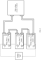
- FIG. 1 shows a simple connection between multi-branch (master/slave) battery boxes and the vehicle.
- the battery packs are connected in parallel to provide high voltage and perform serial communication through a CAN interface.
- a battery box coding scheme used in this application is that a BMS in each battery box is provided with a code detection circuit.
- Such circuit includes N sampling channels, a preset pull-up power channel, a preset pull-down grounding channel, and a voltage divider resistor that can be additionally added to each channel.
- FIG. 2 shows a simplified internal circuit scheme.
- the BMS is directly designed with a built-in 12V pull-up power supply in a sampling circuit corresponding to fixed Channel 2, and therefore voltage that can be collected from such sampling Channel 2 has been fixed as 12V (without considering any loss and accuracy).
- the BMS is designed with a built-in pull-down grounding point in the sampling circuit corresponding to Channel 5, and therefore the voltage of Channel 5 has been fixed as 0V
- different channels are connected directly through an external harness or connected through a voltage divider resistor. In this way, the BMS can collect a corresponding voltage from each sampling channel. Then the BMS processes the collected voltage into a digital signal, and the digits collected from all channels can be combined into a unique digital arrangement which gives the battery box a unique code identity.
- External harnesses are used to help define and distinguish between the unique code identities of the battery boxes, so that one battery pack corresponds to one BMS, thereby facilitating production management and after-sales services.
- disconnection of any battery box will not affect communication or functionality.
- FIG. 3 shows a simplified matching design of external harnesses.
- the sampling result of each channel can only be 12V high level or 0V low level. Therefore, the result is digitalized as 1 for high level and 0 for low level.
- the meanings of the channels are defined according to different requirements, for example:
- Channels 5-8 represent battery box codes
- Channel 5 has been fixed as 0 according to the solution shown in FIG. 1 .
- Channels 6-8 may still be 0 or 1.
- these four channels may be arranged based on combinations of the digits 0/1 as follows and each combination can be defined as a unique identity of a battery box:
- this solution allows use of totally consistent battery boxes that are offered unique identities simply by using different harnesses, thereby facilitating production management and after-sales services.
- This solution can also be used jointly with the vehicle to detect battery box codes. If the detection result is abnormal, a failure alarm is reported, thereby achieving a fool-proofing effect.
- the identity code of the battery box that is specified through multi-channel combination may be planned in advance. Therefore, if the code is not within a defined range, corresponding failure is reported to remind that hardware needs to be checked and maintained.
- the UDS inputs a specified battery box quantity when the vehicle is not operating, then the master BMS can compare a battery box quantity collected in real time with the preset value. If they are inconsistent, a fault alarm is reported to remind the vehicle to check the battery boxes and communication.
- a battery management method is further provided.
- the method is applied to the battery management system in the foregoing embodiment.
- the method includes: determining, by a first battery management module, code data based on voltage of at least one sampling channel in a plurality of sampling channels, and performing identity authentication on a second battery management module based on the code data.
- the method further includes: detecting, by the first battery management module based on a predefined range, whether the code data of the second battery management module is correct, and outputting fault prompt information when incorrect code data is detected.
- the method further includes: determining, by the first battery management module, whether a quantity of received code data is consistent with a preset value, and outputting fault prompt information when the quantity of the received code data is inconsistent with the preset value.
- a battery management apparatus is further provided, where the apparatus is applied to the battery management system described in the foregoing embodiments.
- the apparatus includes:
- the apparatus further includes:
- the apparatus further includes:
Landscapes
- Engineering & Computer Science (AREA)
- Power Engineering (AREA)
- Theoretical Computer Science (AREA)
- General Physics & Mathematics (AREA)
- Physics & Mathematics (AREA)
- Mechanical Engineering (AREA)
- Life Sciences & Earth Sciences (AREA)
- Sustainable Development (AREA)
- Sustainable Energy (AREA)
- Transportation (AREA)
- General Engineering & Computer Science (AREA)
- General Chemical & Material Sciences (AREA)
- Electrochemistry (AREA)
- Chemical Kinetics & Catalysis (AREA)
- Chemical & Material Sciences (AREA)
- Manufacturing & Machinery (AREA)
- Software Systems (AREA)
- Quality & Reliability (AREA)
- Computer Security & Cryptography (AREA)
- Microelectronics & Electronic Packaging (AREA)
- Computer Vision & Pattern Recognition (AREA)
- Computer Hardware Design (AREA)
- Computing Systems (AREA)
- Secondary Cells (AREA)
- Remote Monitoring And Control Of Power-Distribution Networks (AREA)
- Charge And Discharge Circuits For Batteries Or The Like (AREA)
Abstract
Description
- This application refers to
Chinese Patent Application No. 202111598891.1, filed on December 24, 2021 - This application relates to the field of battery technologies, and in particular, to a battery management system and a power supply device.
- As a tie between batteries and users, a battery management system (Battery Management System, BMS) mainly manages secondary batteries, with an aim to improve utilization of batteries and prevent battery over-charging and over-discharging, thus extending service life and monitoring states of the batteries. To implement identification between a plurality of BMSs, a conventional method is to use a software-based serial coding scheme. A master control unit transmits a coding signal to a slave control unit. After receiving the coding signal, the slave control unit performs coding and transmits a current code and a coding signal to a next slave control unit. After all slave control units finish coding, a coding complete flag and a current code count are returned to the master control unit. If failure occurs in any slave control unit during the coding, all subsequent slave control units are unable to continue coding, resulting in low management reliability.
- In view of this, it is necessary to provide a battery management system and a power supply device that can improve management reliability.
- A battery management system includes:
- a first battery management module; and
- a second battery management module in communication connection with the first battery management module;
- where the second battery management module includes a code detection circuit, and the code detection circuit includes a plurality of sampling channels; and
- the first battery management module is configured to determine code data based on voltage of at least one sampling channel in the plurality of sampling channels, and perform identity authentication on the second battery management module based on the code data.
- In the foregoing battery management system, the code detection circuit is disposed in the second battery management module, the first battery management module determines code data based on voltage of at least one sampling channel in the plurality of sampling channels, and then the first battery management module performs identity authentication based on the code data of the second battery management module and obtains an authentication result. The code detection circuit is disposed in the second battery management module, and code data is determined based on voltage of the sampling channel in the code detection circuit, so that failure in any battery management module does not affect code data collection by other battery management modules, thus achieving a high management reliability.
- In one of the embodiments, the first battery management module is further configured to detect, based on a predefined range, whether the code data of the second battery management module is correct, and output fault prompt information when incorrect code data is detected. Fault prompt information is outputted when incorrect code data is detected, facilitating timely troubleshooting.
- In one of the embodiments, the first battery management module is further configured to determine whether a quantity of received code data is consistent with a preset value, and output fault prompt information when the quantity of the received code data is inconsistent with the preset value. Fault prompt information is outputted when the quantity of the received code data is inconsistent with the preset value, further facilitating timely troubleshooting.
- In one of the embodiments, the sampling channels of the code detection circuit include a setting channel and an adjustment channel, where the setting channel is configured to be connected to a power terminal or grounded, and the adjustment channel is configured to be connected to the setting channel through a harness or be connected to the setting channel through a voltage divider resistor. The setting channel of the code detection circuit is connected to the power terminal or grounded, the adjustment channel is connected to the setting channel through the harness or voltage divider resistor, and the voltages of the channels are set in such a way that voltages of some channels are fixed and voltages of the remaining channels are adjustable, so that code information of the battery management modules is adjustable.
- In one of the embodiments, the second battery management module further includes a battery management unit (Battery Management Unit, BMU for short) low-voltage connector, where the BMU low-voltage connector is connected to a corresponding sampling channel of the code detection circuit. The BMU low-voltage connector is connected to the corresponding sampling channel of the code detection circuit, facilitating voltage setting for channels with voltage unconfigured.
- In one of the embodiments, the BMU low-voltage connector is further connected to an external low-voltage connector. In the code detection circuit, the channel with voltage unconfigured is connected to the channel with voltage configured through the external low-voltage connector to perform code configuration for the battery management modules. This can also reduce sizes of the battery management modules.
- In one of the embodiments, the first battery management module and the second battery management module perform serial communication. The first battery management module and the second battery management module perform serial communication, facilitating code data transmission and collection between the battery management modules.
- In one of the embodiments, the first battery management module and the second battery management module perform serial communication through a controller area network (Controller Area Network, CAN for short) interface, allowing for real-time data communication.
- A power supply device includes a battery pack and the foregoing battery management system.
- For the foregoing power supply device, a code detection circuit is disposed in a second battery management module, a first battery management module determines code data based on voltage of at least one sampling channel in a plurality of sampling channels, and then the first battery management module performs identity authentication based on the code data of the second battery management module and obtains an authentication result. The code detection circuit is disposed in the second battery management module, and code data is determined based on voltage of the sampling channel in the code detection circuit, so that failure in any battery management module does not affect code data collection by other battery management modules, thus achieving a high management reliability.
- In one of the embodiments, all the battery packs are connected in parallel to supply power to an external load. All the battery packs are connected in parallel to supply power to an external load. High-voltage power can be supplied to the external load.
- A battery management method, where the method is applied to the foregoing battery management system, and the method includes:
determining, by a first battery management module, code data based on voltage of at least one sampling channel in a plurality of sampling channels, and performing identity authentication on a second battery management module based on the code data. A code detection circuit is disposed in the second battery management module, and the first battery management module determines code data based on voltage of the sampling channel in the code detection circuit, so that failure in any battery management module does not affect code data collection by other battery management modules, thus achieving a high management reliability. - In one of the embodiments, the method further includes:
detecting, by the first battery management module based on a predefined range, whether the code data of the second battery management module is correct, and outputting fault prompt information when incorrect code data is detected. Fault prompt information is outputted when incorrect code data is detected, facilitating timely troubleshooting. - In one of the embodiments, the method further includes:
determining, by the first battery management module, whether a quantity of received code data is consistent with a preset value, and outputting fault prompt information when the quantity of the received code data is inconsistent with the preset value. Fault prompt information is outputted when the quantity of the received code data is inconsistent with the preset value, further facilitating timely troubleshooting. - A battery management apparatus, where the apparatus is applied to the foregoing battery management system, and the apparatus includes: a determining unit, configured to determine code data based on voltage of at least one sampling channel in a plurality of sampling channels; and
an authentication unit, configured to perform identity authentication on a second battery management module based on the code data. - For the foregoing battery management apparatus, a code detection circuit is disposed in the second battery management module, and the battery management apparatus determines code data based on voltage of the sampling channel in the code detection circuit, so that failure in any battery management module does not affect code data collection by other battery management modules, thus achieving a high management reliability.
- In one of the embodiments, the apparatus further includes:
- a detection unit, configured to detect, based on a predefined range, whether the code data of the second battery management module is correct; and
- a first prompt unit, configured to output fault prompt information when the detection unit has detected incorrect code data. Fault prompt information is outputted when incorrect code data is detected, facilitating timely troubleshooting.
- In one of the embodiments, the apparatus further includes:
- a judgment unit, configured to determine whether a quantity of received code data is consistent with a preset value; and
- a second prompt unit, configured to output fault prompt information when the judgment unit detects that the quantity of the received code data is inconsistent with the preset value. Fault prompt information is outputted when the quantity of the received code data is inconsistent with the preset value, further facilitating timely troubleshooting.
-
-
FIG. 1 is a schematic connection diagram of a battery management system according to an embodiment; -
FIG. 2 is a schematic sampling diagram of a BMS containing an internal power supply and a GND according to an embodiment; and -
FIG. 3 is a schematic sampling diagram of a BMS connected to a corresponding external harness according to an embodiment. - To make the objectives, technical solutions, and advantages of this application clearer and more comprehensible, the following further describes this application in detail with reference to the accompanying drawings and embodiments. It should be understood that the specific embodiments described herein are merely used to explain this application but are not intended to limit this application.
- Unless otherwise defined, all technical and scientific terms used herein shall have the same meanings as commonly understood by those skilled in the art to which this application belongs. The terms used herein in the specification of this application are only used to describe specific embodiments, and are not intended to limit this application.
- It should be noted that when a component is deemed as being "connected to" another component, it may be directly connected to the another component, or may be connected to the another component with a component in between. In the following embodiments, if there are electric signals or data transmission among connected circuits, modules, and units, "connection" should be understood as "electrical connection", "communication connection", and the like.
- As used herein, unless otherwise clearly stated in the context, singular forms "a", "an", and "the" can also include plural forms. It should also be noted that, the term "include/contain" or "have" is used to clearly indicate existence of the feature, integer, step, operation, assembly, component, or groups thereof, but does not exclude existence or addition of one or more other features, integers, steps, operations, assemblies, components, or groups thereof. Terms used in this specification include a combination of one or more of the listed items.
- As described in Background, a conventional software-based serial coding scheme is used. A master control unit transmits a coding signal to a slave control unit. After receiving the coding signal, the slave control unit performs coding and transmits a current code and a coding signal to a next slave control unit. After all slave control units finish coding, a coding complete flag and a current code count are returned to the master control unit. Serial coding is time-consuming when there are a large number of slave control units. If failure occurs in any slave control unit during the coding, the subsequent slave control units are unable to continue coding.
- Currently, a major competitiveness for electric vehicles is their endurance mileages. In order to achieve higher mileages, an increasing number of battery boxes have been provided for electric vehicles. In addition to electric vehicles, electric ships, energy storage systems, and the like are all pursuing more battery boxes to obtain more electricity. As a result, the number of cells is increased sharply, putting the BMU, SPI, and CAN-Bus at risk of being overloaded. Only one BMU can no longer satisfy information processing requirements of a plurality of battery boxes.
- Therefore, a master-slave BMS architecture has been developing rapidly. To be specific, in a system, one master BMS performs main control and external interaction, and one slave BMS is configured for each battery pack or each branch in the system for data collection and monitoring, and is also in real-time communication with the master BMS. Such architecture allows a system with a plurality of battery packs as well as each cell to be more controllable.
- For such master-slave architecture, identification of a plurality of BMSs is the most important. If the BMSs cannot be identified, a specific faulty battery pack cannot be accurately located. In addition, without identification and related detection, battery packs are at risk of being disconnected unexpectedly, being a default, or even being redundant. Based on this, this solution aims at providing a simple and rapid BMS hardwired code detection and identification solution for a system with a plurality of battery boxes. In the system with a plurality of battery boxes, through different harness connections, a BMS can obtain identities of all battery boxes in an extremely short time (within 100 milliseconds (ms)) after being woken up, and diagnose the connection status of each battery box. Absence or connection failure of any battery box has zero impact on identification and diagnosis of the remaining battery boxes. A fixed harness connection corresponds to a unique identity code. That means, once a code is known, a corresponding battery box can be immediately and accurately located, facilitating troubleshooting and maintenance of battery boxes. In addition to identification of battery boxes, the following identification can also be provided: carrier types, including aircraft, vehicles, ships, and energy storage; and carrier sub-types, for example, a project may involve vehicles of S/M/L types simultaneously.
- In an embodiment, a battery management system is provided. A battery may be configured to supply power for vehicle-mounted devices or other devices. For ease of understanding, the following is described by using batteries supplying power for vehicle-mounted devices as an example. As shown in
FIG. 1 , a battery management system includes a first battery management module and a second battery management module, and the second battery management module is in communication connection with the first battery management module. The second battery management module includes a code detection circuit, and the code detection circuit includes a plurality of sampling channels. The first battery management module is configured to determine code data based on voltage of at least one sampling channel in the plurality of sampling channels, and perform identity authentication on the second battery management module based on the code data. - Both the first battery management module and the second battery management module may be battery management systems (BMS). The first battery management module serves as a master BMS to perform code detection and identity authentication on the second battery management module. The second battery management module may be provided in a quantity of one or more. In addition, the first battery management module may also be provided with a code detection circuit containing a plurality of sampling channels to identify code data of the first battery management module. For ease of understanding, the following descriptions are based on an example that the first battery management module and the second battery management module are BMSs and are both provided with a code detection circuit.
- In a system with a plurality of battery boxes, each battery box is correspondingly configured with a battery pack and a BMS. The battery pack may include one or more batteries connected in series, and the BMS is used to manage charging/discharging of the battery pack. The battery pack and the BMS are provided in plurality. For example, as shown in
FIG. 1 , the battery pack may includeBattery Pack 1,Battery Pack 2, ..., and Battery Pack N, and the BMS may includeBMS 1,BMS 2, ..., and BMS N. The battery packs are connected in parallel to supply power to an external load. Taking a vehicle-mounted power supply as an example, the battery packs are connected in series, then connected to a high-voltage circuit of the vehicle, and output high-voltage power to the vehicle. All the battery packs are connected in parallel to supply power to an external load. High-voltage power can be supplied to the external load. Different BMSs may be connected in series or in a hybrid mode of serial and parallel connection. In this embodiment, the BMSs are in serial communication. The serial communication between the BMSs facilitates transmission and collection of code data between the BMSs. Further, in an embodiment, the BMSs perform serial communication through a CAN interface, allowing for real-time data communication. Moreover, after being connected in series through a CAN interface, all BMSs are further connected to a vehicle control unit (Vehicle Control Unit) for communication. - Specifically, after being woken up, the BMS for each battery box obtains voltage of some or all of the sampling channels in the coding detector circuit, and determines an identity of the battery box based on voltage combinations of the sampling channels. The voltage of each sampling channel in the detection circuit may be set by connecting the sampling channel to a power terminal, a grounding terminal, or a voltage divider resistor. For example, the voltages of all the channels may be set by separately connecting each sampling channel to the power terminal or grounding terminal in the circuit, or by connecting some sampling channels to the grounding terminal or grounding terminal and connecting the remaining sampling channels to the already-set channels.
- In an embodiment, the sampling channels of the code detection circuit include a setting channel and an adjustment channel, where the setting channel is configured to be connected to a power terminal or grounded, and the adjustment channel is configured to be connected to the setting channel through a harness or be connected to the setting channel through a voltage divider resistor. The setting channel of the code detection circuit is connected to the power terminal or grounded, the adjustment channel is connected to the setting channel through a harness or voltage divider resistor, and the voltages of the channels are set in such a way that voltages of some channels are fixed and voltages of the remaining channels are adjustable, so that code information of the battery management modules is adjustable.
- Further, in an embodiment, as shown in
FIG. 2 , the second battery management module further includes a BMU low-voltage connector (BMU LV connector), and the BMU low-voltage connector is connected to a corresponding sampling channel of the code detection circuit. Specifically, the sampling channels includeChannel 1,Channel 2,Channel 3,Channel 4, ..., andChannel N. Channel 1 andChannel 5 may be set as setting channels, and the remaining channels may be used as adjustment channels. TheChannel 1 is connected to the power terminal, and specifically, to a 12-volt (V) voltage, and theChannel 5 is grounded. The BMU low-voltage connector is connected to the corresponding sampling channel of the code detection circuit, facilitating voltage setting for channels with voltage unconfigured. - In addition, in an embodiment, the BMU low-voltage connector is further connected to an external low-voltage connector. In the code detection circuit, the channel with voltage unconfigured is connected to the channel with voltage configured through the external low-voltage connector to perform code configuration for the battery management modules. This can also reduce sizes of the battery management modules. As shown in
FIG. 3 , using a vehicle-mounted power supply as an example, the external low-voltage connector is a vehicle low-voltage connector (Vehicle LV connector). The remaining sampling channels are separately connected toChannel 1 orChannel 5 by using the vehicle low-voltage connector. Sampling results of the channels may only be 12V high level or 0V low level, and the results are digitalized as 1 for high level or 0 for low level. In this way, the BMS obtains a corresponding voltage from each sampling channel, then the BMS processes the obtained voltage into a digital signal, and thus all the channels can be combined into a unique digital arrangement which gives a unique code identity to a battery box. If the BMS obtains voltage from one sampling channel, one digit obtained by processing is used as code data; and if the BMS obtains voltages from a plurality of sampling channels, a plurality of digits obtained by processing are permutated and combined as code data. - After obtaining the code data of all BMSs, the master BMS performs identity authentication based on the code data to obtain identity information of the corresponding battery box. To be specific, the master BMS may analyze the code data to obtain information such as battery box identities, carrier classes, and carrier types as an authentication result. Finally, the master BMS can further output the obtained authentication result to a vehicle control unit.
- In an embodiment, the first battery management module is further configured to detect, based on a predefined range, whether the code data of the second battery management module is correct, and output fault prompt information when incorrect code data is detected. Fault prompt information is outputted when incorrect code data is detected, facilitating timely troubleshooting. Because an identity code of a battery box that is set through combinations of a plurality of channels has been planned in advance, if the code is not within the defined range, a corresponding fault prompt may be reported. For example, fault prompt information is sent to the vehicle control unit to remind that hardware needs to be checked and maintained.
- Further, in an embodiment, the first battery management module is further configured to determine whether a quantity of received code data is consistent with a preset value, and output fault prompt information when the quantity of the received code data is inconsistent with the preset value. Fault prompt information is outputted when the quantity of the received code data is inconsistent with the preset value, further facilitating timely troubleshooting. Specifically, with cooperation of the vehicle, for example, through unified diagnostic services (Unified Diagnostic Services, UDS for short), the specified battery box quantity may be inputted when the vehicle is not operating. Then the master BMS may compare the battery box quantity obtained in real time with the preset value. If they are inconsistent, the master BMS may output fault prompt information to the vehicle control unit, reminding, through a fault alarm, to check the battery boxes and communication of the vehicle.
- In the foregoing battery management system, the code detection circuit is disposed in the second battery management module, the first battery management module determines code data based on voltage of at least one sampling channel in the plurality of sampling channels, and then the first battery management module performs identity authentication based on the code data of the second battery management module and obtains an authentication result. The code detection circuit is disposed in the second battery management module, and code data is determined based on voltage of the sampling channel in the code detection circuit, so that failure in any battery management module does not affect code data collection by other battery management modules, thus achieving a high management reliability.
- In an embodiment, a power supply device is further provided, including a battery pack and the foregoing battery management system. All battery packs are connected in parallel to supply power to an external load. All the battery packs are connected in parallel to supply power to the external load. High-voltage power can be supplied to the external load.
- Specifically, the battery management system includes a first battery management module and a second battery management module, and the second battery management module is in communication connection with the first battery management module. The second battery management module includes a code detection circuit, and the code detection circuit includes a plurality of sampling channels. The first battery management module is configured to determine code data based on voltage of at least one sampling channel in the plurality of sampling channels, and perform identity authentication on the second battery management module based on the code data.
- In an embodiment, the sampling channels of the code detection circuit include a setting channel and an adjustment channel, where the setting channel is configured to be connected to a power terminal or grounded, and the adjustment channel is configured to be connected to the setting channel through a harness, or be connected to the setting channel through a voltage divider resistor. The setting channel of the code detection circuit is connected to the power terminal or grounded, the adjustment channel is connected to the setting channel through a harness or voltage divider resistor, and the voltages of the channels are set in such a way that voltages of some channels are fixed and voltages of the remaining channels are adjustable, so that code information of the battery management modules is adjustable.
- Further, in an embodiment, the second battery management module further includes a BMU low-voltage connector, and the BMU low-voltage connector is connected to a corresponding sampling channel of the code detection circuit. The BMU low-voltage connector is connected to the corresponding sampling channel of the code detection circuit, facilitating voltage setting for channels with voltage unconfigured.
- In addition, in an embodiment, the BMU low-voltage connector is further connected to an external low-voltage connector. In the code detection circuit, the channel with voltage unconfigured is connected to the channel with voltage configured through the external low-voltage connector to perform code configuration for the battery management modules. This can also reduce sizes of the battery management modules.
- In an embodiment, the first battery management module is further configured to detect, based on a predefined range, whether the code data of the second battery management module is correct, and output fault prompt information when incorrect code data is detected. Fault prompt information is outputted when incorrect code data is detected, facilitating timely troubleshooting.
- Further, in an embodiment, the first battery management module is further configured to determine whether a quantity of received code data is consistent with a preset value, and output fault prompt information when the quantity of the received code data is inconsistent with the preset value. Fault prompt information is outputted when the quantity of the received code data is inconsistent with the preset value, further facilitating timely troubleshooting.
- For the foregoing power supply device, the code detection circuit is disposed in the second battery management module, the first battery management module determines code data based on voltage of at least one sampling channel in the plurality of sampling channels, and then the first battery management module performs identity authentication based on the code data of the second battery management module and obtains an authentication result. The code detection circuit is disposed in the second battery management module, and code data is determined based on voltage of the sampling channel in the code detection circuit, so that failure in any battery management module does not affect code data collection by other battery management modules, thus achieving a high management reliability.
- For better understanding of the foregoing battery management system and power supply device, the following provides detail with reference to specific embodiments.
- In the BMS code detection and identification solution according to this application, the BMS performs voltage sampling through a harness to perform coding and diagnosis on each battery box. A unique identity code of each battery box comes from the unique combination of sampled values obtained from a plurality of sampling channels. A fixed harness arrangement provides a fixed sampling result, so that a code of a battery box is also fixed. No matter whether the battery boxes are connected in series or parallel, disconnection or communication failure of any battery box will not affect use of the remaining battery boxes.
- Specifically,
FIG. 1 shows a simple connection between multi-branch (master/slave) battery boxes and the vehicle. The battery packs are connected in parallel to provide high voltage and perform serial communication through a CAN interface. Based on the foregoing architecture, a battery box coding scheme used in this application is that a BMS in each battery box is provided with a code detection circuit. Such circuit includes N sampling channels, a preset pull-up power channel, a preset pull-down grounding channel, and a voltage divider resistor that can be additionally added to each channel. -
FIG. 2 shows a simplified internal circuit scheme. The BMS is directly designed with a built-in 12V pull-up power supply in a sampling circuit corresponding to fixedChannel 2, and therefore voltage that can be collected fromsuch sampling Channel 2 has been fixed as 12V (without considering any loss and accuracy). Similarly, the BMS is designed with a built-in pull-down grounding point in the sampling circuit corresponding toChannel 5, and therefore the voltage ofChannel 5 has been fixed as 0V Next, different channels are connected directly through an external harness or connected through a voltage divider resistor. In this way, the BMS can collect a corresponding voltage from each sampling channel. Then the BMS processes the collected voltage into a digital signal, and the digits collected from all channels can be combined into a unique digital arrangement which gives the battery box a unique code identity. - External harnesses are used to help define and distinguish between the unique code identities of the battery boxes, so that one battery pack corresponds to one BMS, thereby facilitating production management and after-sales services. In the solution based on such architecture, disconnection of any battery box will not affect communication or functionality.
-
FIG. 3 shows a simplified matching design of external harnesses. According to the solution inFIG. 3 , without considering voltage drop, power loss, and the like, the sampling result of each channel can only be 12V high level or 0V low level. Therefore, the result is digitalized as 1 for high level and 0 for low level. The meanings of the channels are defined according to different requirements, for example: - 1. Channel 1: Carrier - 0: Car; 1: Ship
- 2. Channel 2: Type - 0: BEV; 1: PHEV
- 3. Channel 3: Type - 0: Car; 1: Bus
- 4. Channel 4: Car/ship specification - 0: S; 1: M
- 5. Multi-channel combination: Identity code -
Battery box 1/2/3... - For example, assuming that Channels 5-8 represent battery box codes,
Channel 5 has been fixed as 0 according to the solution shown inFIG. 1 . Channels 6-8 may still be 0 or 1. Then these four channels may be arranged based on combinations of the digits 0/1 as follows and each combination can be defined as a unique identity of a battery box: - 0000 -
Battery box 1 - 0001 -
Battery box 2 - 0011 -
Battery box 3 - 0100 -
Battery box 4 - 0101 -
Battery box 5 - 0110 -
Battery box 6 - 0111 -
Battery box 7 - Therefore, this solution allows use of totally consistent battery boxes that are offered unique identities simply by using different harnesses, thereby facilitating production management and after-sales services. This solution can also be used jointly with the vehicle to detect battery box codes. If the detection result is abnormal, a failure alarm is reported, thereby achieving a fool-proofing effect.
- Based on the above solution, the identity code of the battery box that is specified through multi-channel combination may be planned in advance. Therefore, if the code is not within a defined range, corresponding failure is reported to remind that hardware needs to be checked and maintained.
- Additionally, with cooperation of the vehicle, for example, the UDS inputs a specified battery box quantity when the vehicle is not operating, then the master BMS can compare a battery box quantity collected in real time with the preset value. If they are inconsistent, a fault alarm is reported to remind the vehicle to check the battery boxes and communication.
- There are only two possibilities for each channel in the foregoing solution. To reduce the number of channels by increasing the possibility of each channel, a resistor may be added on the harness side or the BMS side. In this way, voltage division implemented through different resistor combinations can increase gradients of voltage obtained from each channel, beyond the limitation of only 0 or 1.
- In an embodiment, a battery management method is further provided. The method is applied to the battery management system in the foregoing embodiment. The method includes:
determining, by a first battery management module, code data based on voltage of at least one sampling channel in a plurality of sampling channels, and performing identity authentication on a second battery management module based on the code data. - Further, in an embodiment, the method further includes:
detecting, by the first battery management module based on a predefined range, whether the code data of the second battery management module is correct, and outputting fault prompt information when incorrect code data is detected. - Further, in an embodiment, the method further includes:
determining, by the first battery management module, whether a quantity of received code data is consistent with a preset value, and outputting fault prompt information when the quantity of the received code data is inconsistent with the preset value. - For specific limitations on the battery management method, reference may be made to relevant content of the foregoing battery management system embodiments of this application. Details are not described herein again.
- In an embodiment, a battery management apparatus is further provided, where the apparatus is applied to the battery management system described in the foregoing embodiments. The apparatus includes:
- a determining unit, configured to determine code data based on voltage of at least one sampling channel in a plurality of sampling channels; and
- an authentication unit, configured to perform identity authentication on a second battery management module based on the code data.
- Further, in an embodiment, the apparatus further includes:
- a detection unit, configured to detect, based on a predefined range, whether the code data of the second battery management module is correct; and
- a first prompt unit, configured to output fault prompt information when the detection unit has detected incorrect code data.
- Further, in an embodiment, the apparatus further includes:
- a judgment unit, configured to determine whether a quantity of received code data is consistent with a preset value; and
- a second prompt unit, configured to output fault prompt information when the judgment unit detects that the quantity of the received code data is inconsistent with the preset value.
- For specific limitations on the battery management apparatus, reference may be made to relevant content of the foregoing battery management system embodiments of this application. Details are not described herein again.
- Technical features in the foregoing embodiments may be combined in any way. For brevity of description, possible combinations of the technical features in the foregoing embodiments are not described all. However, as long as there is no contradiction among combinations of these technical features, all the combinations should be considered within a range recorded in this specification.
- The foregoing embodiments only represent several implementations of this application, and descriptions thereof are specific and detailed, but should not be construed as a limitation on the scope of this patent. It should be noted that those of ordinary skill in the art may further make several modifications and improvements without departing from the concept of this application, and these modifications and improvements also fall within the protection scope of this application. Therefore, the protection scope of this application should be subject to the appended claims.
Claims (16)
- A battery management system, comprising:a first battery management module; anda second battery management module in communication connection with the first battery management module; whereinthe second battery management module comprises a code detection circuit, and the code detection circuit comprises a plurality of sampling channels; andthe first battery management module is configured to determine code data based on voltage of at least one sampling channel in the plurality of sampling channels, and perform identity authentication on the second battery management module based on the code data.
- The battery management system according to claim 1, wherein the first battery management module is further configured to detect, based on a predefined range, whether the code data of the second battery management module is correct, and output fault prompt information when incorrect code data is detected.
- The battery management system according to claim 1, wherein the first battery management module is further configured to determine whether a quantity of received code data is consistent with a preset value, and output fault prompt information when the quantity of the received code data is inconsistent with the preset value.
- The battery management system according to any one of claims 1 to 3, wherein the sampling channels of the code detection circuit comprise a setting channel and an adjustment channel, wherein the setting channel is configured to be connected to a power terminal or grounded, and the adjustment channel is configured to be connected to the setting channel through a harness, or be connected to the setting channel through a voltage divider resistor.
- The battery management system according to any one of claims 1 to 3, wherein the second battery management module further comprises a BMU low-voltage connector, wherein the BMU low-voltage connector is connected to a corresponding sampling channel of the code detection circuit.
- The battery management system according to claim 5, wherein the BMU low-voltage connector is further connected to an external low-voltage connector.
- The battery management system according to any one of claims 1 to 6, wherein the first battery management module and the second battery management module perform serial communication.
- The battery management system according to claim 7, wherein the first battery management module and the second battery management module perform serial communication through a CAN interface.
- A power supply device, comprising battery packs and the battery management system according to any one of claims 1 to 8.
- The power supply device according to claim 9, wherein all the battery packs are connected in parallel to supply power to an external load.
- A battery management method, wherein the method is applied to the battery management system according to any one of claims 1 to 8, and the method comprises:
determining, by a first battery management module, code data based on voltage of at least one sampling channel in a plurality of sampling channels, and performing identity authentication on a second battery management module based on the code data. - The method according to claim 11, wherein the method further comprises:
detecting, by the first battery management module based on a predefined range, whether the code data of the second battery management module is correct, and outputting fault prompt information when incorrect code data is detected. - The method according to claim 11, wherein the method further comprises:
determining, by the first battery management module, whether a quantity of received code data is consistent with a preset value, and outputting fault prompt information when the quantity of the received code data is inconsistent with the preset value. - A battery management apparatus, wherein the apparatus is applied to the battery management system according to any one of claims 1 to 8, and the apparatus comprises:a determining unit, configured to determine code data based on voltage of at least one sampling channel in a plurality of sampling channels; andan authentication unit, configured to perform identity authentication on a second battery management module based on the code data.
- The apparatus according to claim 14, wherein the apparatus further comprises:a detection unit, configured to detect, based on a predefined range, whether the code data of the second battery management module is correct; anda first prompt unit, configured to output fault prompt information when the detection unit has detected incorrect code data.
- The apparatus according to claim 14, wherein the apparatus further comprises:a judgment unit, configured to determine whether a quantity of received code data is consistent with a preset value; anda second prompt unit, configured to output fault prompt information when the judgment unit detects that the quantity of the received code data is inconsistent with the preset value.
Applications Claiming Priority (2)
| Application Number | Priority Date | Filing Date | Title |
|---|---|---|---|
| CN202111598891.1A CN115811103B (en) | 2021-12-24 | 2021-12-24 | Battery management system and power supply device |
| PCT/CN2022/094473 WO2023115804A1 (en) | 2021-12-24 | 2022-05-23 | Battery management system and power supply device |
Publications (3)
| Publication Number | Publication Date |
|---|---|
| EP4231410A1 true EP4231410A1 (en) | 2023-08-23 |
| EP4231410A4 EP4231410A4 (en) | 2024-01-17 |
| EP4231410B1 EP4231410B1 (en) | 2025-04-02 |
Family
ID=84389288
Family Applications (1)
| Application Number | Title | Priority Date | Filing Date |
|---|---|---|---|
| EP22785676.2A Active EP4231410B1 (en) | 2021-12-24 | 2022-05-23 | Battery management system and power supply device |
Country Status (9)
| Country | Link |
|---|---|
| US (1) | US12399229B2 (en) |
| EP (1) | EP4231410B1 (en) |
| JP (1) | JP7561204B2 (en) |
| KR (1) | KR20230098500A (en) |
| CN (1) | CN115811103B (en) |
| DK (1) | DK4231410T3 (en) |
| ES (1) | ES3033927T3 (en) |
| HU (1) | HUE071521T2 (en) |
| WO (1) | WO2023115804A1 (en) |
Cited By (1)
| Publication number | Priority date | Publication date | Assignee | Title |
|---|---|---|---|---|
| EP4641876A1 (en) * | 2024-04-26 | 2025-10-29 | Volvo Truck Corporation | Secured modification of battery pack parameters |
Families Citing this family (8)
| Publication number | Priority date | Publication date | Assignee | Title |
|---|---|---|---|---|
| CN116488309B (en) * | 2023-06-21 | 2024-02-27 | 深圳市华芯控股有限公司 | Switch signal series transmission and failure compensation circuit and device |
| CN117261595B (en) * | 2023-08-21 | 2025-03-07 | 东风商用车有限公司 | Battery module electrical position automatic identification system and method based on resistance voltage division |
| CN120056800A (en) * | 2023-11-29 | 2025-05-30 | 宁德时代新能源科技股份有限公司 | Battery replacing system and coding method |
| WO2025165673A1 (en) * | 2024-01-30 | 2025-08-07 | Sensata Technologies, Inc. | Parallel and/or series hybrid pack modes in battery management system |
| CN118051441B (en) * | 2024-04-03 | 2024-11-05 | 百思科新能源技术(青岛)有限公司 | Battery management unit software architecture and automatic code generation method |
| CN118249392B (en) * | 2024-05-28 | 2024-07-26 | 惠州市盛微电子有限公司 | Standardized flow battery management system |
| CN119299047A (en) * | 2024-09-13 | 2025-01-10 | 杭州利沃得电源有限公司 | Automatic coding system, method and device for energy storage battery clustering |
| CN119493068B (en) * | 2024-12-18 | 2026-03-13 | 广东汇天航空航天科技有限公司 | Battery management system testing system, methods and flying car |
Family Cites Families (21)
| Publication number | Priority date | Publication date | Assignee | Title |
|---|---|---|---|---|
| CN1979992A (en) * | 2005-12-07 | 2007-06-13 | 比亚迪股份有限公司 | Charge-discharge protection circuit of secondary cell group |
| JP5466586B2 (en) * | 2009-10-05 | 2014-04-09 | プライムアースEvエナジー株式会社 | Battery management device |
| US9070908B2 (en) * | 2011-03-11 | 2015-06-30 | Samsung Sdi Co., Ltd. | Battery system, controlling method of the same, and energy storage system including the battery system |
| US9774193B2 (en) * | 2011-10-26 | 2017-09-26 | Eetrex, Inc. | Battery cell charge balancing |
| CN102514498B (en) * | 2011-11-23 | 2014-11-12 | 湖南南车时代电动汽车股份有限公司 | Identification method and device of battery management system sub-module |
| US9478981B2 (en) * | 2012-09-26 | 2016-10-25 | Samsung Sdi Co., Ltd. | Battery system having identifiers and energy storage system including the same |
| DE102014102366B4 (en) * | 2013-02-25 | 2021-03-04 | Rp-Technik Gmbh | Energy supply device with battery monitoring and battery monitoring process |
| JP6260192B2 (en) * | 2013-10-21 | 2018-01-17 | 三菱自動車工業株式会社 | battery pack |
| JP6467816B2 (en) * | 2014-08-21 | 2019-02-13 | 株式会社村田製作所 | Power storage system |
| CN105843763A (en) * | 2016-03-23 | 2016-08-10 | 上海航天测控通信研究所 | CAN bus dynamic configuration device and method |
| CN106657427B (en) * | 2016-08-12 | 2022-07-22 | 上海火亮新能源科技有限公司 | Battery module address distribution system and method |
| KR102005394B1 (en) * | 2017-03-16 | 2019-10-01 | 주식회사 엘지화학 | A method of automatically setting the communication terminal resistance of an energy storage device(ESS) |
| CN106931717B (en) * | 2017-03-21 | 2019-09-27 | 合肥美的电冰箱有限公司 | Gear shifting device and refrigeration device |
| CN206579487U (en) * | 2017-03-21 | 2017-10-24 | 北京新能源汽车股份有限公司 | A battery management system, battery pack and electric vehicle |
| US10589630B2 (en) * | 2017-10-13 | 2020-03-17 | Ford Global Technologies, Llc | Electrified vehicle drivetrain monitoring system |
| CN109004292A (en) * | 2018-06-05 | 2018-12-14 | 安徽锐能科技有限公司 | A kind of battery management system with automatic addressing unit |
| JP7031504B2 (en) * | 2018-06-11 | 2022-03-08 | 株式会社デンソー | Battery system |
| US11890487B2 (en) * | 2018-09-27 | 2024-02-06 | Yona Peled | Method and apparatus for multi-channel simultaneously high power magnetic coil driver |
| JP6935793B2 (en) * | 2018-12-04 | 2021-09-15 | 株式会社デンソー | Battery system |
| CN112578699A (en) * | 2019-09-27 | 2021-03-30 | 大陆汽车电子(连云港)有限公司 | Interface assembly for coupling a controller and a wiring harness |
| FR3121284B1 (en) * | 2021-03-25 | 2024-08-16 | St@Rtec Dev | IMMERSION COOLED BATTERY WITH WIRELESS COMMUNICATION SYSTEM |
-
2021
- 2021-12-24 CN CN202111598891.1A patent/CN115811103B/en active Active
-
2022
- 2022-05-23 EP EP22785676.2A patent/EP4231410B1/en active Active
- 2022-05-23 KR KR1020227034000A patent/KR20230098500A/en active Pending
- 2022-05-23 JP JP2022557161A patent/JP7561204B2/en active Active
- 2022-05-23 HU HUE22785676A patent/HUE071521T2/en unknown
- 2022-05-23 ES ES22785676T patent/ES3033927T3/en active Active
- 2022-05-23 DK DK22785676.2T patent/DK4231410T3/en active
- 2022-05-23 WO PCT/CN2022/094473 patent/WO2023115804A1/en not_active Ceased
- 2022-10-17 US US17/967,842 patent/US12399229B2/en active Active
Cited By (1)
| Publication number | Priority date | Publication date | Assignee | Title |
|---|---|---|---|---|
| EP4641876A1 (en) * | 2024-04-26 | 2025-10-29 | Volvo Truck Corporation | Secured modification of battery pack parameters |
Also Published As
| Publication number | Publication date |
|---|---|
| DK4231410T3 (en) | 2025-06-30 |
| JP7561204B2 (en) | 2024-10-03 |
| US12399229B2 (en) | 2025-08-26 |
| EP4231410B1 (en) | 2025-04-02 |
| JP2024505763A (en) | 2024-02-08 |
| KR20230098500A (en) | 2023-07-04 |
| CN115811103B (en) | 2024-05-10 |
| HUE071521T2 (en) | 2025-09-28 |
| EP4231410A4 (en) | 2024-01-17 |
| CN115811103A (en) | 2023-03-17 |
| US20230204683A1 (en) | 2023-06-29 |
| ES3033927T3 (en) | 2025-08-11 |
| WO2023115804A1 (en) | 2023-06-29 |
Similar Documents
| Publication | Publication Date | Title |
|---|---|---|
| EP4231410B1 (en) | Battery management system and power supply device | |
| US9529053B2 (en) | Battery management system and method for determining the charge state battery cells, battery and motor vehicle comprising a battery management system | |
| DE102011079126B4 (en) | Battery management system, battery, motor vehicle with battery management system and method for monitoring a battery | |
| US9187000B2 (en) | Battery pack and electrically driven automobile | |
| JP5647210B2 (en) | Integrated circuit for battery cell | |
| US11031640B2 (en) | Battery pack, battery monitoring device, and vehicle | |
| CN111605437B (en) | Battery management system and battery management method | |
| CN109302852A (en) | Manage devices and power systems | |
| CN105226759A (en) | Synchronous sampling method and sampling system of battery management system | |
| WO2022136434A2 (en) | Method and equipment for monitoring a failure in a high-voltage circuit of a vehicle, and high-voltage circuit system | |
| DE102022115443B4 (en) | In-vehicle system and junction box | |
| CN110605964B (en) | A high-voltage interlock detection method and system | |
| CN206374571U (en) | Electric vehicle and its battery management system | |
| US9985321B2 (en) | Battery system | |
| KR20250085417A (en) | Device and method of detecting pe open for electric vehicle charging controller | |
| EP4417455A1 (en) | Multichannel insulation monitoring device for an evse, and method | |
| CN114927744A (en) | Battery system, battery pack, automobile and control method of battery system | |
| CN120559497B (en) | Diagnostic method for voltage sampling, battery management system, battery device and equipment | |
| CN215850764U (en) | Detection circuit for accurately positioning high-voltage interlocking fault plug-in | |
| EP4583359A1 (en) | Method and apparatus for setting battery pack identifier | |
| CN219892233U (en) | Health management and intelligent maintenance system equipment for storage battery pack | |
| CN222850728U (en) | Sampling circuits, energy storage devices and electric equipment | |
| CN213734664U (en) | Battery voltage and temperature monitoring system | |
| DE102010030747A1 (en) | battery system | |
| CN209981415U (en) | Modular Mounted BMS System |
Legal Events
| Date | Code | Title | Description |
|---|---|---|---|
| STAA | Information on the status of an ep patent application or granted ep patent |
Free format text: STATUS: UNKNOWN |
|
| STAA | Information on the status of an ep patent application or granted ep patent |
Free format text: STATUS: THE INTERNATIONAL PUBLICATION HAS BEEN MADE |
|
| PUAI | Public reference made under article 153(3) epc to a published international application that has entered the european phase |
Free format text: ORIGINAL CODE: 0009012 |
|
| STAA | Information on the status of an ep patent application or granted ep patent |
Free format text: STATUS: REQUEST FOR EXAMINATION WAS MADE |
|
| 17P | Request for examination filed |
Effective date: 20221031 |
|
| AK | Designated contracting states |
Kind code of ref document: A1 Designated state(s): AL AT BE BG CH CY CZ DE DK EE ES FI FR GB GR HR HU IE IS IT LI LT LU LV MC MK MT NL NO PL PT RO RS SE SI SK SM TR |
|
| A4 | Supplementary search report drawn up and despatched |
Effective date: 20231215 |
|
| RIC1 | Information provided on ipc code assigned before grant |
Ipc: H02J 7/34 20060101ALI20231211BHEP Ipc: H02J 7/00 20060101ALI20231211BHEP Ipc: H01M 10/48 20060101ALI20231211BHEP Ipc: B60L 58/21 20190101ALI20231211BHEP Ipc: B60L 3/00 20190101ALI20231211BHEP Ipc: B60L 58/18 20190101ALI20231211BHEP Ipc: H01M 10/42 20060101AFI20231211BHEP |
|
| RAP1 | Party data changed (applicant data changed or rights of an application transferred) |
Owner name: CONTEMPORARY AMPEREX TECHNOLOGY(HONG KONG) LIMITED |
|
| GRAP | Despatch of communication of intention to grant a patent |
Free format text: ORIGINAL CODE: EPIDOSNIGR1 |
|
| STAA | Information on the status of an ep patent application or granted ep patent |
Free format text: STATUS: GRANT OF PATENT IS INTENDED |
|
| RIC1 | Information provided on ipc code assigned before grant |
Ipc: H02J 7/34 20060101ALI20241217BHEP Ipc: H02J 7/00 20060101ALI20241217BHEP Ipc: H01M 10/48 20060101ALI20241217BHEP Ipc: B60L 58/21 20190101ALI20241217BHEP Ipc: B60L 3/00 20190101ALI20241217BHEP Ipc: B60L 58/18 20190101ALI20241217BHEP Ipc: H01M 10/42 20060101AFI20241217BHEP |
|
| INTG | Intention to grant announced |
Effective date: 20250107 |
|
| GRAS | Grant fee paid |
Free format text: ORIGINAL CODE: EPIDOSNIGR3 |
|
| GRAA | (expected) grant |
Free format text: ORIGINAL CODE: 0009210 |
|
| STAA | Information on the status of an ep patent application or granted ep patent |
Free format text: STATUS: THE PATENT HAS BEEN GRANTED |
|
| AK | Designated contracting states |
Kind code of ref document: B1 Designated state(s): AL AT BE BG CH CY CZ DE DK EE ES FI FR GB GR HR HU IE IS IT LI LT LU LV MC MK MT NL NO PL PT RO RS SE SI SK SM TR |
|
| DAV | Request for validation of the european patent (deleted) | ||
| DAX | Request for extension of the european patent (deleted) | ||
| REG | Reference to a national code |
Ref country code: GB Ref legal event code: FG4D |
|
| REG | Reference to a national code |
Ref country code: CH Ref legal event code: EP |
|
| REG | Reference to a national code |
Ref country code: DE Ref legal event code: R096 Ref document number: 602022012688 Country of ref document: DE |
|
| REG | Reference to a national code |
Ref country code: IE Ref legal event code: FG4D |
|
| P01 | Opt-out of the competence of the unified patent court (upc) registered |
Free format text: CASE NUMBER: APP_19241/2025 Effective date: 20250422 |
|
| REG | Reference to a national code |
Ref country code: DK Ref legal event code: T3 Effective date: 20250625 |
|
| PGFP | Annual fee paid to national office [announced via postgrant information from national office to epo] |
Ref country code: AT Payment date: 20250721 Year of fee payment: 4 |
|
| REG | Reference to a national code |
Ref country code: NL Ref legal event code: MP Effective date: 20250402 |
|
| REG | Reference to a national code |
Ref country code: ES Ref legal event code: FG2A Ref document number: 3033927 Country of ref document: ES Kind code of ref document: T3 Effective date: 20250811 |
|
| PG25 | Lapsed in a contracting state [announced via postgrant information from national office to epo] |
Ref country code: NL Free format text: LAPSE BECAUSE OF FAILURE TO SUBMIT A TRANSLATION OF THE DESCRIPTION OR TO PAY THE FEE WITHIN THE PRESCRIBED TIME-LIMIT Effective date: 20250402 |
|
| REG | Reference to a national code |
Ref country code: AT Ref legal event code: MK05 Ref document number: 1782228 Country of ref document: AT Kind code of ref document: T Effective date: 20250402 |
|
| REG | Reference to a national code |
Ref country code: HU Ref legal event code: AG4A Ref document number: E071521 Country of ref document: HU |
|
| PG25 | Lapsed in a contracting state [announced via postgrant information from national office to epo] |
Ref country code: FI Free format text: LAPSE BECAUSE OF FAILURE TO SUBMIT A TRANSLATION OF THE DESCRIPTION OR TO PAY THE FEE WITHIN THE PRESCRIBED TIME-LIMIT Effective date: 20250402 Ref country code: PT Free format text: LAPSE BECAUSE OF FAILURE TO SUBMIT A TRANSLATION OF THE DESCRIPTION OR TO PAY THE FEE WITHIN THE PRESCRIBED TIME-LIMIT Effective date: 20250804 |
|
| REG | Reference to a national code |
Ref country code: LT Ref legal event code: MG9D |
|
| PG25 | Lapsed in a contracting state [announced via postgrant information from national office to epo] |
Ref country code: GR Free format text: LAPSE BECAUSE OF FAILURE TO SUBMIT A TRANSLATION OF THE DESCRIPTION OR TO PAY THE FEE WITHIN THE PRESCRIBED TIME-LIMIT Effective date: 20250703 |
|
| PG25 | Lapsed in a contracting state [announced via postgrant information from national office to epo] |
Ref country code: PL Free format text: LAPSE BECAUSE OF FAILURE TO SUBMIT A TRANSLATION OF THE DESCRIPTION OR TO PAY THE FEE WITHIN THE PRESCRIBED TIME-LIMIT Effective date: 20250402 |
|
| PG25 | Lapsed in a contracting state [announced via postgrant information from national office to epo] |
Ref country code: BG Free format text: LAPSE BECAUSE OF FAILURE TO SUBMIT A TRANSLATION OF THE DESCRIPTION OR TO PAY THE FEE WITHIN THE PRESCRIBED TIME-LIMIT Effective date: 20250402 |
|
| PG25 | Lapsed in a contracting state [announced via postgrant information from national office to epo] |
Ref country code: HR Free format text: LAPSE BECAUSE OF FAILURE TO SUBMIT A TRANSLATION OF THE DESCRIPTION OR TO PAY THE FEE WITHIN THE PRESCRIBED TIME-LIMIT Effective date: 20250402 Ref country code: AT Free format text: LAPSE BECAUSE OF FAILURE TO SUBMIT A TRANSLATION OF THE DESCRIPTION OR TO PAY THE FEE WITHIN THE PRESCRIBED TIME-LIMIT Effective date: 20250402 |
|
| PG25 | Lapsed in a contracting state [announced via postgrant information from national office to epo] |
Ref country code: RS Free format text: LAPSE BECAUSE OF FAILURE TO SUBMIT A TRANSLATION OF THE DESCRIPTION OR TO PAY THE FEE WITHIN THE PRESCRIBED TIME-LIMIT Effective date: 20250702 |
|
| PG25 | Lapsed in a contracting state [announced via postgrant information from national office to epo] |
Ref country code: IS Free format text: LAPSE BECAUSE OF FAILURE TO SUBMIT A TRANSLATION OF THE DESCRIPTION OR TO PAY THE FEE WITHIN THE PRESCRIBED TIME-LIMIT Effective date: 20250802 |
|
| PG25 | Lapsed in a contracting state [announced via postgrant information from national office to epo] |
Ref country code: LV Free format text: LAPSE BECAUSE OF FAILURE TO SUBMIT A TRANSLATION OF THE DESCRIPTION OR TO PAY THE FEE WITHIN THE PRESCRIBED TIME-LIMIT Effective date: 20250402 |
|
| REG | Reference to a national code |
Ref country code: CH Ref legal event code: H13 Free format text: ST27 STATUS EVENT CODE: U-0-0-H10-H13 (AS PROVIDED BY THE NATIONAL OFFICE) Effective date: 20251223 |
|
| REG | Reference to a national code |
Ref country code: DE Ref legal event code: R097 Ref document number: 602022012688 Country of ref document: DE |
|
| PG25 | Lapsed in a contracting state [announced via postgrant information from national office to epo] |
Ref country code: SM Free format text: LAPSE BECAUSE OF FAILURE TO SUBMIT A TRANSLATION OF THE DESCRIPTION OR TO PAY THE FEE WITHIN THE PRESCRIBED TIME-LIMIT Effective date: 20250402 |
|
| PG25 | Lapsed in a contracting state [announced via postgrant information from national office to epo] |
Ref country code: LU Free format text: LAPSE BECAUSE OF NON-PAYMENT OF DUE FEES Effective date: 20250523 |
|
| PG25 | Lapsed in a contracting state [announced via postgrant information from national office to epo] |
Ref country code: CH Free format text: LAPSE BECAUSE OF NON-PAYMENT OF DUE FEES Effective date: 20250531 |
|
| PG25 | Lapsed in a contracting state [announced via postgrant information from national office to epo] |
Ref country code: CZ Free format text: LAPSE BECAUSE OF FAILURE TO SUBMIT A TRANSLATION OF THE DESCRIPTION OR TO PAY THE FEE WITHIN THE PRESCRIBED TIME-LIMIT Effective date: 20250402 |
|
| PG25 | Lapsed in a contracting state [announced via postgrant information from national office to epo] |
Ref country code: EE Free format text: LAPSE BECAUSE OF FAILURE TO SUBMIT A TRANSLATION OF THE DESCRIPTION OR TO PAY THE FEE WITHIN THE PRESCRIBED TIME-LIMIT Effective date: 20250402 |
|
| PG25 | Lapsed in a contracting state [announced via postgrant information from national office to epo] |
Ref country code: SK Free format text: LAPSE BECAUSE OF FAILURE TO SUBMIT A TRANSLATION OF THE DESCRIPTION OR TO PAY THE FEE WITHIN THE PRESCRIBED TIME-LIMIT Effective date: 20250402 |
|
| REG | Reference to a national code |
Ref country code: BE Ref legal event code: MM Effective date: 20250531 |
|
| PG25 | Lapsed in a contracting state [announced via postgrant information from national office to epo] |
Ref country code: MC Free format text: LAPSE BECAUSE OF FAILURE TO SUBMIT A TRANSLATION OF THE DESCRIPTION OR TO PAY THE FEE WITHIN THE PRESCRIBED TIME-LIMIT Effective date: 20250402 |
|
| PLBE | No opposition filed within time limit |
Free format text: ORIGINAL CODE: 0009261 |
|
| STAA | Information on the status of an ep patent application or granted ep patent |
Free format text: STATUS: NO OPPOSITION FILED WITHIN TIME LIMIT |
|
| REG | Reference to a national code |
Ref country code: CH Ref legal event code: L10 Free format text: ST27 STATUS EVENT CODE: U-0-0-L10-L00 (AS PROVIDED BY THE NATIONAL OFFICE) Effective date: 20260211 |
|
| PG25 | Lapsed in a contracting state [announced via postgrant information from national office to epo] |
Ref country code: RO Free format text: LAPSE BECAUSE OF FAILURE TO SUBMIT A TRANSLATION OF THE DESCRIPTION OR TO PAY THE FEE WITHIN THE PRESCRIBED TIME-LIMIT Effective date: 20250402 |
|
| 26N | No opposition filed |
Effective date: 20260105 |
|
| PGFP | Annual fee paid to national office [announced via postgrant information from national office to epo] |
Ref country code: GB Payment date: 20260331 Year of fee payment: 5 |
|
| PG25 | Lapsed in a contracting state [announced via postgrant information from national office to epo] |
Ref country code: IE Free format text: LAPSE BECAUSE OF NON-PAYMENT OF DUE FEES Effective date: 20250523 |
|
| PG25 | Lapsed in a contracting state [announced via postgrant information from national office to epo] |
Ref country code: BE Free format text: LAPSE BECAUSE OF NON-PAYMENT OF DUE FEES Effective date: 20250531 |
|
| PGFP | Annual fee paid to national office [announced via postgrant information from national office to epo] |
Ref country code: HU Payment date: 20260520 Year of fee payment: 5 |
|
| PG25 | Lapsed in a contracting state [announced via postgrant information from national office to epo] |
Ref country code: LT Free format text: LAPSE BECAUSE OF FAILURE TO SUBMIT A TRANSLATION OF THE DESCRIPTION OR TO PAY THE FEE WITHIN THE PRESCRIBED TIME-LIMIT Effective date: 20250402 |
|
| PGFP | Annual fee paid to national office [announced via postgrant information from national office to epo] |
Ref country code: ES Payment date: 20260601 Year of fee payment: 5 |
|
| PGFP | Annual fee paid to national office [announced via postgrant information from national office to epo] |
Ref country code: DK Payment date: 20260518 Year of fee payment: 5 |
|
| PGFP | Annual fee paid to national office [announced via postgrant information from national office to epo] |
Ref country code: IT Payment date: 20260527 Year of fee payment: 5 |
|
| PGFP | Annual fee paid to national office [announced via postgrant information from national office to epo] |
Ref country code: DE Payment date: 20260522 Year of fee payment: 5 |
|
| PGFP | Annual fee paid to national office [announced via postgrant information from national office to epo] |
Ref country code: NO Payment date: 20260520 Year of fee payment: 5 |
|
| PGFP | Annual fee paid to national office [announced via postgrant information from national office to epo] |
Ref country code: FR Payment date: 20260525 Year of fee payment: 5 |
|
| PG25 | Lapsed in a contracting state [announced via postgrant information from national office to epo] |
Ref country code: CY Free format text: LAPSE BECAUSE OF FAILURE TO SUBMIT A TRANSLATION OF THE DESCRIPTION OR TO PAY THE FEE WITHIN THE PRESCRIBED TIME-LIMIT Effective date: 20250402 Ref country code: SE Free format text: LAPSE BECAUSE OF FAILURE TO SUBMIT A TRANSLATION OF THE DESCRIPTION OR TO PAY THE FEE WITHIN THE PRESCRIBED TIME-LIMIT Effective date: 20250402 |