EP4231403A2 - Secondary battery - Google Patents
Secondary battery Download PDFInfo
- Publication number
- EP4231403A2 EP4231403A2 EP23174763.5A EP23174763A EP4231403A2 EP 4231403 A2 EP4231403 A2 EP 4231403A2 EP 23174763 A EP23174763 A EP 23174763A EP 4231403 A2 EP4231403 A2 EP 4231403A2
- Authority
- EP
- European Patent Office
- Prior art keywords
- region
- electrode lead
- step region
- transition region
- secondary battery
- Prior art date
- Legal status (The legal status is an assumption and is not a legal conclusion. Google has not performed a legal analysis and makes no representation as to the accuracy of the status listed.)
- Pending
Links
- 230000007704 transition Effects 0.000 claims abstract description 89
- 210000000746 body region Anatomy 0.000 claims abstract description 47
- 238000007789 sealing Methods 0.000 claims abstract description 41
- 238000004806 packaging method and process Methods 0.000 claims abstract description 33
- 239000010410 layer Substances 0.000 claims description 48
- 239000012785 packaging film Substances 0.000 claims description 38
- 229920006280 packaging film Polymers 0.000 claims description 38
- 229910052751 metal Inorganic materials 0.000 claims description 18
- 239000002184 metal Substances 0.000 claims description 18
- 239000011241 protective layer Substances 0.000 claims description 9
- 238000004804 winding Methods 0.000 claims description 3
- 238000007906 compression Methods 0.000 description 22
- 230000006835 compression Effects 0.000 description 18
- 230000006872 improvement Effects 0.000 description 12
- 238000010586 diagram Methods 0.000 description 8
- 238000000034 method Methods 0.000 description 8
- 230000008569 process Effects 0.000 description 8
- 239000000084 colloidal system Substances 0.000 description 7
- 239000000463 material Substances 0.000 description 6
- PXHVJJICTQNCMI-UHFFFAOYSA-N Nickel Chemical compound [Ni] PXHVJJICTQNCMI-UHFFFAOYSA-N 0.000 description 4
- 229910052782 aluminium Inorganic materials 0.000 description 4
- XAGFODPZIPBFFR-UHFFFAOYSA-N aluminium Chemical compound [Al] XAGFODPZIPBFFR-UHFFFAOYSA-N 0.000 description 4
- 238000007599 discharging Methods 0.000 description 3
- 239000011888 foil Substances 0.000 description 3
- 238000000465 moulding Methods 0.000 description 3
- RYGMFSIKBFXOCR-UHFFFAOYSA-N Copper Chemical compound [Cu] RYGMFSIKBFXOCR-UHFFFAOYSA-N 0.000 description 2
- 239000004743 Polypropylene Substances 0.000 description 2
- 229910000831 Steel Inorganic materials 0.000 description 2
- 230000009471 action Effects 0.000 description 2
- 239000000853 adhesive Substances 0.000 description 2
- 230000001070 adhesive effect Effects 0.000 description 2
- 239000011230 binding agent Substances 0.000 description 2
- 230000004927 fusion Effects 0.000 description 2
- 239000007773 negative electrode material Substances 0.000 description 2
- 229910052759 nickel Inorganic materials 0.000 description 2
- 229920006255 plastic film Polymers 0.000 description 2
- 239000002985 plastic film Substances 0.000 description 2
- -1 polypropylene Polymers 0.000 description 2
- 229920001155 polypropylene Polymers 0.000 description 2
- 239000007774 positive electrode material Substances 0.000 description 2
- 239000010959 steel Substances 0.000 description 2
- OKTJSMMVPCPJKN-UHFFFAOYSA-N Carbon Chemical compound [C] OKTJSMMVPCPJKN-UHFFFAOYSA-N 0.000 description 1
- 239000004677 Nylon Substances 0.000 description 1
- 239000002202 Polyethylene glycol Substances 0.000 description 1
- 230000009286 beneficial effect Effects 0.000 description 1
- 229910052802 copper Inorganic materials 0.000 description 1
- 239000010949 copper Substances 0.000 description 1
- 239000011889 copper foil Substances 0.000 description 1
- QHGJSLXSVXVKHZ-UHFFFAOYSA-N dilithium;dioxido(dioxo)manganese Chemical compound [Li+].[Li+].[O-][Mn]([O-])(=O)=O QHGJSLXSVXVKHZ-UHFFFAOYSA-N 0.000 description 1
- 239000003792 electrolyte Substances 0.000 description 1
- 239000010439 graphite Substances 0.000 description 1
- 229910002804 graphite Inorganic materials 0.000 description 1
- GELKBWJHTRAYNV-UHFFFAOYSA-K lithium iron phosphate Chemical compound [Li+].[Fe+2].[O-]P([O-])([O-])=O GELKBWJHTRAYNV-UHFFFAOYSA-K 0.000 description 1
- 229920001778 nylon Polymers 0.000 description 1
- 229920001223 polyethylene glycol Polymers 0.000 description 1
- 229910052710 silicon Inorganic materials 0.000 description 1
- 239000010703 silicon Substances 0.000 description 1
- KKEYFWRCBNTPAC-UHFFFAOYSA-L terephthalate(2-) Chemical compound [O-]C(=O)C1=CC=C(C([O-])=O)C=C1 KKEYFWRCBNTPAC-UHFFFAOYSA-L 0.000 description 1
- 230000037303 wrinkles Effects 0.000 description 1
Images


Classifications
-
- H—ELECTRICITY
- H01—ELECTRIC ELEMENTS
- H01M—PROCESSES OR MEANS, e.g. BATTERIES, FOR THE DIRECT CONVERSION OF CHEMICAL ENERGY INTO ELECTRICAL ENERGY
- H01M10/00—Secondary cells; Manufacture thereof
- H01M10/04—Construction or manufacture in general
-
- H—ELECTRICITY
- H01—ELECTRIC ELEMENTS
- H01M—PROCESSES OR MEANS, e.g. BATTERIES, FOR THE DIRECT CONVERSION OF CHEMICAL ENERGY INTO ELECTRICAL ENERGY
- H01M50/00—Constructional details or processes of manufacture of the non-active parts of electrochemical cells other than fuel cells, e.g. hybrid cells
- H01M50/50—Current conducting connections for cells or batteries
- H01M50/531—Electrode connections inside a battery casing
- H01M50/533—Electrode connections inside a battery casing characterised by the shape of the leads or tabs
-
- H—ELECTRICITY
- H01—ELECTRIC ELEMENTS
- H01M—PROCESSES OR MEANS, e.g. BATTERIES, FOR THE DIRECT CONVERSION OF CHEMICAL ENERGY INTO ELECTRICAL ENERGY
- H01M50/00—Constructional details or processes of manufacture of the non-active parts of electrochemical cells other than fuel cells, e.g. hybrid cells
- H01M50/10—Primary casings; Jackets or wrappings
- H01M50/102—Primary casings; Jackets or wrappings characterised by their shape or physical structure
- H01M50/105—Pouches or flexible bags
-
- B—PERFORMING OPERATIONS; TRANSPORTING
- B29—WORKING OF PLASTICS; WORKING OF SUBSTANCES IN A PLASTIC STATE IN GENERAL
- B29C—SHAPING OR JOINING OF PLASTICS; SHAPING OF MATERIAL IN A PLASTIC STATE, NOT OTHERWISE PROVIDED FOR; AFTER-TREATMENT OF THE SHAPED PRODUCTS, e.g. REPAIRING
- B29C65/00—Joining or sealing of preformed parts, e.g. welding of plastics materials; Apparatus therefor
- B29C65/02—Joining or sealing of preformed parts, e.g. welding of plastics materials; Apparatus therefor by heating, with or without pressure
-
- B—PERFORMING OPERATIONS; TRANSPORTING
- B29—WORKING OF PLASTICS; WORKING OF SUBSTANCES IN A PLASTIC STATE IN GENERAL
- B29C—SHAPING OR JOINING OF PLASTICS; SHAPING OF MATERIAL IN A PLASTIC STATE, NOT OTHERWISE PROVIDED FOR; AFTER-TREATMENT OF THE SHAPED PRODUCTS, e.g. REPAIRING
- B29C66/00—General aspects of processes or apparatus for joining preformed parts
- B29C66/01—General aspects dealing with the joint area or with the area to be joined
- B29C66/05—Particular design of joint configurations
- B29C66/10—Particular design of joint configurations particular design of the joint cross-sections
- B29C66/11—Joint cross-sections comprising a single joint-segment, i.e. one of the parts to be joined comprising a single joint-segment in the joint cross-section
- B29C66/112—Single lapped joints
- B29C66/1122—Single lap to lap joints, i.e. overlap joints
-
- B—PERFORMING OPERATIONS; TRANSPORTING
- B29—WORKING OF PLASTICS; WORKING OF SUBSTANCES IN A PLASTIC STATE IN GENERAL
- B29C—SHAPING OR JOINING OF PLASTICS; SHAPING OF MATERIAL IN A PLASTIC STATE, NOT OTHERWISE PROVIDED FOR; AFTER-TREATMENT OF THE SHAPED PRODUCTS, e.g. REPAIRING
- B29C66/00—General aspects of processes or apparatus for joining preformed parts
- B29C66/01—General aspects dealing with the joint area or with the area to be joined
- B29C66/32—Measures for keeping the burr form under control; Avoiding burr formation; Shaping the burr
- B29C66/322—Providing cavities in the joined article to collect the burr
-
- B—PERFORMING OPERATIONS; TRANSPORTING
- B29—WORKING OF PLASTICS; WORKING OF SUBSTANCES IN A PLASTIC STATE IN GENERAL
- B29C—SHAPING OR JOINING OF PLASTICS; SHAPING OF MATERIAL IN A PLASTIC STATE, NOT OTHERWISE PROVIDED FOR; AFTER-TREATMENT OF THE SHAPED PRODUCTS, e.g. REPAIRING
- B29C66/00—General aspects of processes or apparatus for joining preformed parts
- B29C66/40—General aspects of joining substantially flat articles, e.g. plates, sheets or web-like materials; Making flat seams in tubular or hollow articles; Joining single elements to substantially flat surfaces
- B29C66/41—Joining substantially flat articles ; Making flat seams in tubular or hollow articles
- B29C66/43—Joining a relatively small portion of the surface of said articles
- B29C66/433—Casing-in, i.e. enclosing an element between two sheets by an outlined seam
-
- B—PERFORMING OPERATIONS; TRANSPORTING
- B29—WORKING OF PLASTICS; WORKING OF SUBSTANCES IN A PLASTIC STATE IN GENERAL
- B29C—SHAPING OR JOINING OF PLASTICS; SHAPING OF MATERIAL IN A PLASTIC STATE, NOT OTHERWISE PROVIDED FOR; AFTER-TREATMENT OF THE SHAPED PRODUCTS, e.g. REPAIRING
- B29C66/00—General aspects of processes or apparatus for joining preformed parts
- B29C66/70—General aspects of processes or apparatus for joining preformed parts characterised by the composition, physical properties or the structure of the material of the parts to be joined; Joining with non-plastics material
- B29C66/72—General aspects of processes or apparatus for joining preformed parts characterised by the composition, physical properties or the structure of the material of the parts to be joined; Joining with non-plastics material characterised by the structure of the material of the parts to be joined
- B29C66/723—General aspects of processes or apparatus for joining preformed parts characterised by the composition, physical properties or the structure of the material of the parts to be joined; Joining with non-plastics material characterised by the structure of the material of the parts to be joined being multi-layered
- B29C66/7232—General aspects of processes or apparatus for joining preformed parts characterised by the composition, physical properties or the structure of the material of the parts to be joined; Joining with non-plastics material characterised by the structure of the material of the parts to be joined being multi-layered comprising a non-plastics layer
- B29C66/72321—General aspects of processes or apparatus for joining preformed parts characterised by the composition, physical properties or the structure of the material of the parts to be joined; Joining with non-plastics material characterised by the structure of the material of the parts to be joined being multi-layered comprising a non-plastics layer consisting of metals or their alloys
-
- B—PERFORMING OPERATIONS; TRANSPORTING
- B29—WORKING OF PLASTICS; WORKING OF SUBSTANCES IN A PLASTIC STATE IN GENERAL
- B29C—SHAPING OR JOINING OF PLASTICS; SHAPING OF MATERIAL IN A PLASTIC STATE, NOT OTHERWISE PROVIDED FOR; AFTER-TREATMENT OF THE SHAPED PRODUCTS, e.g. REPAIRING
- B29C66/00—General aspects of processes or apparatus for joining preformed parts
- B29C66/80—General aspects of machine operations or constructions and parts thereof
- B29C66/81—General aspects of the pressing elements, i.e. the elements applying pressure on the parts to be joined in the area to be joined, e.g. the welding jaws or clamps
- B29C66/814—General aspects of the pressing elements, i.e. the elements applying pressure on the parts to be joined in the area to be joined, e.g. the welding jaws or clamps characterised by the design of the pressing elements, e.g. of the welding jaws or clamps
- B29C66/8141—General aspects of the pressing elements, i.e. the elements applying pressure on the parts to be joined in the area to be joined, e.g. the welding jaws or clamps characterised by the design of the pressing elements, e.g. of the welding jaws or clamps characterised by the surface geometry of the part of the pressing elements, e.g. welding jaws or clamps, coming into contact with the parts to be joined
- B29C66/81431—General aspects of the pressing elements, i.e. the elements applying pressure on the parts to be joined in the area to be joined, e.g. the welding jaws or clamps characterised by the design of the pressing elements, e.g. of the welding jaws or clamps characterised by the surface geometry of the part of the pressing elements, e.g. welding jaws or clamps, coming into contact with the parts to be joined comprising a single cavity, e.g. a groove
-
- B—PERFORMING OPERATIONS; TRANSPORTING
- B29—WORKING OF PLASTICS; WORKING OF SUBSTANCES IN A PLASTIC STATE IN GENERAL
- B29C—SHAPING OR JOINING OF PLASTICS; SHAPING OF MATERIAL IN A PLASTIC STATE, NOT OTHERWISE PROVIDED FOR; AFTER-TREATMENT OF THE SHAPED PRODUCTS, e.g. REPAIRING
- B29C66/00—General aspects of processes or apparatus for joining preformed parts
- B29C66/80—General aspects of machine operations or constructions and parts thereof
- B29C66/83—General aspects of machine operations or constructions and parts thereof characterised by the movement of the joining or pressing tools
- B29C66/832—Reciprocating joining or pressing tools
- B29C66/8322—Joining or pressing tools reciprocating along one axis
- B29C66/83221—Joining or pressing tools reciprocating along one axis cooperating reciprocating tools, each tool reciprocating along one axis
-
- H—ELECTRICITY
- H01—ELECTRIC ELEMENTS
- H01M—PROCESSES OR MEANS, e.g. BATTERIES, FOR THE DIRECT CONVERSION OF CHEMICAL ENERGY INTO ELECTRICAL ENERGY
- H01M50/00—Constructional details or processes of manufacture of the non-active parts of electrochemical cells other than fuel cells, e.g. hybrid cells
- H01M50/10—Primary casings; Jackets or wrappings
- H01M50/116—Primary casings; Jackets or wrappings characterised by the material
- H01M50/117—Inorganic material
- H01M50/119—Metals
-
- H—ELECTRICITY
- H01—ELECTRIC ELEMENTS
- H01M—PROCESSES OR MEANS, e.g. BATTERIES, FOR THE DIRECT CONVERSION OF CHEMICAL ENERGY INTO ELECTRICAL ENERGY
- H01M50/00—Constructional details or processes of manufacture of the non-active parts of electrochemical cells other than fuel cells, e.g. hybrid cells
- H01M50/10—Primary casings; Jackets or wrappings
- H01M50/116—Primary casings; Jackets or wrappings characterised by the material
- H01M50/121—Organic material
-
- H—ELECTRICITY
- H01—ELECTRIC ELEMENTS
- H01M—PROCESSES OR MEANS, e.g. BATTERIES, FOR THE DIRECT CONVERSION OF CHEMICAL ENERGY INTO ELECTRICAL ENERGY
- H01M50/00—Constructional details or processes of manufacture of the non-active parts of electrochemical cells other than fuel cells, e.g. hybrid cells
- H01M50/10—Primary casings; Jackets or wrappings
- H01M50/116—Primary casings; Jackets or wrappings characterised by the material
- H01M50/124—Primary casings; Jackets or wrappings characterised by the material having a layered structure
- H01M50/126—Primary casings; Jackets or wrappings characterised by the material having a layered structure comprising three or more layers
- H01M50/129—Primary casings; Jackets or wrappings characterised by the material having a layered structure comprising three or more layers with two or more layers of only organic material
-
- H—ELECTRICITY
- H01—ELECTRIC ELEMENTS
- H01M—PROCESSES OR MEANS, e.g. BATTERIES, FOR THE DIRECT CONVERSION OF CHEMICAL ENERGY INTO ELECTRICAL ENERGY
- H01M50/00—Constructional details or processes of manufacture of the non-active parts of electrochemical cells other than fuel cells, e.g. hybrid cells
- H01M50/10—Primary casings; Jackets or wrappings
- H01M50/172—Arrangements of electric connectors penetrating the casing
- H01M50/174—Arrangements of electric connectors penetrating the casing adapted for the shape of the cells
- H01M50/178—Arrangements of electric connectors penetrating the casing adapted for the shape of the cells for pouch or flexible bag cells
-
- H—ELECTRICITY
- H01—ELECTRIC ELEMENTS
- H01M—PROCESSES OR MEANS, e.g. BATTERIES, FOR THE DIRECT CONVERSION OF CHEMICAL ENERGY INTO ELECTRICAL ENERGY
- H01M50/00—Constructional details or processes of manufacture of the non-active parts of electrochemical cells other than fuel cells, e.g. hybrid cells
- H01M50/10—Primary casings; Jackets or wrappings
- H01M50/183—Sealing members
- H01M50/184—Sealing members characterised by their shape or structure
-
- B—PERFORMING OPERATIONS; TRANSPORTING
- B29—WORKING OF PLASTICS; WORKING OF SUBSTANCES IN A PLASTIC STATE IN GENERAL
- B29C—SHAPING OR JOINING OF PLASTICS; SHAPING OF MATERIAL IN A PLASTIC STATE, NOT OTHERWISE PROVIDED FOR; AFTER-TREATMENT OF THE SHAPED PRODUCTS, e.g. REPAIRING
- B29C66/00—General aspects of processes or apparatus for joining preformed parts
- B29C66/70—General aspects of processes or apparatus for joining preformed parts characterised by the composition, physical properties or the structure of the material of the parts to be joined; Joining with non-plastics material
- B29C66/71—General aspects of processes or apparatus for joining preformed parts characterised by the composition, physical properties or the structure of the material of the parts to be joined; Joining with non-plastics material characterised by the composition of the plastics material of the parts to be joined
-
- B—PERFORMING OPERATIONS; TRANSPORTING
- B29—WORKING OF PLASTICS; WORKING OF SUBSTANCES IN A PLASTIC STATE IN GENERAL
- B29C—SHAPING OR JOINING OF PLASTICS; SHAPING OF MATERIAL IN A PLASTIC STATE, NOT OTHERWISE PROVIDED FOR; AFTER-TREATMENT OF THE SHAPED PRODUCTS, e.g. REPAIRING
- B29C66/00—General aspects of processes or apparatus for joining preformed parts
- B29C66/70—General aspects of processes or apparatus for joining preformed parts characterised by the composition, physical properties or the structure of the material of the parts to be joined; Joining with non-plastics material
- B29C66/73—General aspects of processes or apparatus for joining preformed parts characterised by the composition, physical properties or the structure of the material of the parts to be joined; Joining with non-plastics material characterised by the intensive physical properties of the material of the parts to be joined, by the optical properties of the material of the parts to be joined, by the extensive physical properties of the parts to be joined, by the state of the material of the parts to be joined or by the material of the parts to be joined being a thermoplastic or a thermoset
- B29C66/735—General aspects of processes or apparatus for joining preformed parts characterised by the composition, physical properties or the structure of the material of the parts to be joined; Joining with non-plastics material characterised by the intensive physical properties of the material of the parts to be joined, by the optical properties of the material of the parts to be joined, by the extensive physical properties of the parts to be joined, by the state of the material of the parts to be joined or by the material of the parts to be joined being a thermoplastic or a thermoset characterised by the extensive physical properties of the parts to be joined
- B29C66/7352—Thickness, e.g. very thin
-
- B—PERFORMING OPERATIONS; TRANSPORTING
- B29—WORKING OF PLASTICS; WORKING OF SUBSTANCES IN A PLASTIC STATE IN GENERAL
- B29C—SHAPING OR JOINING OF PLASTICS; SHAPING OF MATERIAL IN A PLASTIC STATE, NOT OTHERWISE PROVIDED FOR; AFTER-TREATMENT OF THE SHAPED PRODUCTS, e.g. REPAIRING
- B29C66/00—General aspects of processes or apparatus for joining preformed parts
- B29C66/80—General aspects of machine operations or constructions and parts thereof
- B29C66/81—General aspects of the pressing elements, i.e. the elements applying pressure on the parts to be joined in the area to be joined, e.g. the welding jaws or clamps
- B29C66/814—General aspects of the pressing elements, i.e. the elements applying pressure on the parts to be joined in the area to be joined, e.g. the welding jaws or clamps characterised by the design of the pressing elements, e.g. of the welding jaws or clamps
- B29C66/8141—General aspects of the pressing elements, i.e. the elements applying pressure on the parts to be joined in the area to be joined, e.g. the welding jaws or clamps characterised by the design of the pressing elements, e.g. of the welding jaws or clamps characterised by the surface geometry of the part of the pressing elements, e.g. welding jaws or clamps, coming into contact with the parts to be joined
- B29C66/81411—General aspects of the pressing elements, i.e. the elements applying pressure on the parts to be joined in the area to be joined, e.g. the welding jaws or clamps characterised by the design of the pressing elements, e.g. of the welding jaws or clamps characterised by the surface geometry of the part of the pressing elements, e.g. welding jaws or clamps, coming into contact with the parts to be joined characterised by its cross-section, e.g. transversal or longitudinal, being non-flat
- B29C66/81425—General aspects of the pressing elements, i.e. the elements applying pressure on the parts to be joined in the area to be joined, e.g. the welding jaws or clamps characterised by the design of the pressing elements, e.g. of the welding jaws or clamps characterised by the surface geometry of the part of the pressing elements, e.g. welding jaws or clamps, coming into contact with the parts to be joined characterised by its cross-section, e.g. transversal or longitudinal, being non-flat being stepped, e.g. comprising a shoulder
-
- B—PERFORMING OPERATIONS; TRANSPORTING
- B29—WORKING OF PLASTICS; WORKING OF SUBSTANCES IN A PLASTIC STATE IN GENERAL
- B29K—INDEXING SCHEME ASSOCIATED WITH SUBCLASSES B29B, B29C OR B29D, RELATING TO MOULDING MATERIALS OR TO MATERIALS FOR MOULDS, REINFORCEMENTS, FILLERS OR PREFORMED PARTS, e.g. INSERTS
- B29K2705/00—Use of metals, their alloys or their compounds, for preformed parts, e.g. for inserts
- B29K2705/02—Aluminium
-
- B—PERFORMING OPERATIONS; TRANSPORTING
- B29—WORKING OF PLASTICS; WORKING OF SUBSTANCES IN A PLASTIC STATE IN GENERAL
- B29K—INDEXING SCHEME ASSOCIATED WITH SUBCLASSES B29B, B29C OR B29D, RELATING TO MOULDING MATERIALS OR TO MATERIALS FOR MOULDS, REINFORCEMENTS, FILLERS OR PREFORMED PARTS, e.g. INSERTS
- B29K2705/00—Use of metals, their alloys or their compounds, for preformed parts, e.g. for inserts
- B29K2705/08—Transition metals
- B29K2705/12—Iron
-
- B—PERFORMING OPERATIONS; TRANSPORTING
- B29—WORKING OF PLASTICS; WORKING OF SUBSTANCES IN A PLASTIC STATE IN GENERAL
- B29L—INDEXING SCHEME ASSOCIATED WITH SUBCLASS B29C, RELATING TO PARTICULAR ARTICLES
- B29L2031/00—Other particular articles
- B29L2031/34—Electrical apparatus, e.g. sparking plugs or parts thereof
- B29L2031/3468—Batteries, accumulators or fuel cells
-
- Y—GENERAL TAGGING OF NEW TECHNOLOGICAL DEVELOPMENTS; GENERAL TAGGING OF CROSS-SECTIONAL TECHNOLOGIES SPANNING OVER SEVERAL SECTIONS OF THE IPC; TECHNICAL SUBJECTS COVERED BY FORMER USPC CROSS-REFERENCE ART COLLECTIONS [XRACs] AND DIGESTS
- Y02—TECHNOLOGIES OR APPLICATIONS FOR MITIGATION OR ADAPTATION AGAINST CLIMATE CHANGE
- Y02E—REDUCTION OF GREENHOUSE GAS [GHG] EMISSIONS, RELATED TO ENERGY GENERATION, TRANSMISSION OR DISTRIBUTION
- Y02E60/00—Enabling technologies; Technologies with a potential or indirect contribution to GHG emissions mitigation
- Y02E60/10—Energy storage using batteries
-
- Y—GENERAL TAGGING OF NEW TECHNOLOGICAL DEVELOPMENTS; GENERAL TAGGING OF CROSS-SECTIONAL TECHNOLOGIES SPANNING OVER SEVERAL SECTIONS OF THE IPC; TECHNICAL SUBJECTS COVERED BY FORMER USPC CROSS-REFERENCE ART COLLECTIONS [XRACs] AND DIGESTS
- Y02—TECHNOLOGIES OR APPLICATIONS FOR MITIGATION OR ADAPTATION AGAINST CLIMATE CHANGE
- Y02P—CLIMATE CHANGE MITIGATION TECHNOLOGIES IN THE PRODUCTION OR PROCESSING OF GOODS
- Y02P70/00—Climate change mitigation technologies in the production process for final industrial or consumer products
- Y02P70/50—Manufacturing or production processes characterised by the final manufactured product
Definitions
- an included angle between an outer surface of the first transition region and the outer surface of the first step region is 100° ⁇ 170°.
- the packaging bag includes two packaging films, the electrode assembly is located between the two packaging films, and the two packaging films are connected at edges to form the sealing portion.
- Each packaging film includes a protective layer, a metal layer and a connecting layer, the connecting layer is disposed on a surface of the metal layer facing the electrode assembly, and the protective layer is disposed on a surface of the metal layer away from the electrode assembly.
- connecting layers of the two packaging films are fused into one body; and in the first step region, the connecting layer of each packaging film is fused to the first part.
- the packaging bag 2 includes two packaging films 22, and the two packaging films 22 are arranged up and down in the thickness direction Z. With reference to FIG. 6 , at least one packaging film 22 is stamped to form a concave chamber, and the electrode assembly 1 is located between the two packaging films 22 and housed in the concave chamber.
- the first transition region 214 connects the main body region 211 and the first step region 212, the first transition region 214 has two outer surfaces disposed oppositely in the thickness direction Z, and the two outer surfaces are inclined toward a direction close to the first step region 212 relative to the main body region 211.
- the outer surface of the first transition region 214 connects an outer surface of the main body region 211 and the outer surface of the first step region 212.
- the outer surface of the first transition region 214 may extend from an end part of the outer surface of the first step region 212, and is inclined toward a direction close to the outer surface of the main body region 211 relative to the outer surface of the first step region 212.
- spacing between the two outer surfaces of the first transition region 214 is L. In a direction in which the main body region 211 points to the electrode lead 3, a value of L gradually increases.
Landscapes
- Chemical & Material Sciences (AREA)
- Chemical Kinetics & Catalysis (AREA)
- Electrochemistry (AREA)
- General Chemical & Material Sciences (AREA)
- Engineering & Computer Science (AREA)
- Mechanical Engineering (AREA)
- Inorganic Chemistry (AREA)
- Manufacturing & Machinery (AREA)
- Sealing Battery Cases Or Jackets (AREA)
- Connection Of Batteries Or Terminals (AREA)
- Secondary Cells (AREA)
Abstract
Description
- The present application relates to the field of batteries, and in particular, to a secondary battery.
- With the rapid development of portable electronic devices, requirements for battery energy density are getting higher and higher. In a secondary battery, a packaging bag made of an aluminum plastic film or a steel plastic film may be used to replace a metal housing to reduce weight of the battery and increase energy density.
- An electrode assembly of the secondary battery is housed in the packaging bag, and edges of the packaging bag may be connected in a sealing manner by thermal compression to form a sealing portion. Certainly, to achieve charging and discharging of the electrode assembly, the secondary battery further includes an electrode lead and an insulating member, the electrode lead is connected to the electrode assembly and extends to an outside of the packaging bag, and the insulating member surrounds an outer side of the electrode lead and isolates the electrode lead from the sealing portion. However, a region of the sealing portion close to an edge of the insulating member has a difference in height to form a step. In the thermal compression, the sealing portion wrinkles and is damaged easily at the step, which affects sealing performance of the packaging bag.
- In view of the problem in the background, an objective of the present application is to provide a secondary battery, which can reduce a risk of puncturing a packaging bag, improve sealing performance of the packaging bag, and improve safety performance.
- To achieve the foregoing objective, the present application provides a secondary battery including an electrode assembly, a packaging bag, an electrode lead and an insulating member. The electrode assembly is housed in the packaging bag, an edge of the packaging bag has a sealing portion, and the electrode lead is connected to the electrode assembly and passes through the sealing portion. The sealing portion includes a main body region, a first step region and a first transition region, the first step region is located on two sides of the electrode lead in a thickness direction, the main body region and the first transition region are located on a same side of the first step region in a width direction, and the first transition region is connected between the first step region and the main body region. The insulating member surrounds an outer side of the electrode lead and isolates the sealing portion from the electrode lead; the insulating member includes a first part, and in the thickness direction, the first part is located between the electrode lead and the first step region and covers the electrode lead from two sides. A sum of thicknesses of the first step region, the first part and the electrode lead is H1, a thickness of the main body region is H2, and H1 > H2. A minimum distance between the electrode lead and an outer surface of the first transition region is D1, a minimum distance between the electrode lead and an outer surface of the first step region is D2, and D1 ≥ D2.
- As an improvement of the secondary battery of the present application, the first transition region connects the main body region and the first step region, the first transition region has two outer surfaces disposed oppositely in the thickness direction, and the two outer surfaces are inclined toward a direction close to the first step region relative to the main body region.
- As an improvement of the secondary battery of the present application, an included angle between an outer surface of the first transition region and the outer surface of the first step region is 100°~170°.
- As an improvement of the secondary battery of the present application, the electrode lead includes a base portion and an edge portion, the edge portion is connected to the base portion and located on one side of the base portion close to the first transition region in the width direction. In a direction away from the base portion, a thickness of the edge portion gradually reduces.
- As an improvement of the secondary battery of the present application, the edge portion has a first surface facing the first step region, and the base portion has a second surface facing the first step region. The first surface is connected to the second surface, and an included angle between the two is greater than or equal to 120°.
- As an improvement of the secondary battery of the present application, a minimum thickness of the edge portion is greater than 100 µm.
- As an improvement of the secondary battery of the present application, in the width direction, a ratio of a size of the edge portion to a size of the base portion is 0.1-0.4.
- As an improvement of the secondary battery of the present application, in the width direction, the first step region is beyond the electrode lead. The insulating member further includes a second part, the second part is connection to the first part, and a part of the first step region beyond the electrode lead covers the second part from two sides.
- As an improvement of the secondary battery of the present application, the sealing portion includes a second step region, and the second step region connects the main body region and the first transition region. The insulating member further includes a third part and a fourth part, the third part extends from an end of the second part away from the electrode lead, and the fourth part extends from an end of the third part away from the second part. In the thickness direction, the first transition region covers the third part from two sides, and the second step region covers the fourth part from two sides. A sum of thicknesses of the second step region and the fourth part is H4, and H2 < H4 < H1.
- As an improvement of the secondary battery of the present application, a minimum thickness of the edge portion is H5, and H5 < H4.
- As an improvement of the secondary battery of the present application, in a direction in which the second part points to the fourth part, a thickness of the third part gradually reduces.
- As an improvement of the secondary battery of the present application, a value of D2 is greater than 150 µm.
- As an improvement of the secondary battery of the present application, the packaging bag includes two packaging films, the electrode assembly is located between the two packaging films, and the two packaging films are connected at edges to form the sealing portion. Each packaging film includes a protective layer, a metal layer and a connecting layer, the connecting layer is disposed on a surface of the metal layer facing the electrode assembly, and the protective layer is disposed on a surface of the metal layer away from the electrode assembly. In the main body region, connecting layers of the two packaging films are fused into one body; and in the first step region, the connecting layer of each packaging film is fused to the first part.
- The beneficial effects of the present application are as follows: since there is a difference in height between a main body region and a first step region, in a process of thermal compression, a first transition region is stretched, which results in that its strength becomes smaller. Therefore, in the present application, preferably, Di ≥ D2, thereby reducing a risk of puncturing the first transition region by an end part of an electrode lead, improving sealing performance of a packaging bag, and improving safety performance.
-
-
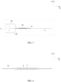
FIG. 1 is a schematic diagram of a secondary battery provided in a first embodiment of the present application; -
FIG. 2 is a sectional view of a secondary battery provided in a first embodiment of the present application; -
FIG. 3 is an enlarged view of a block part ofFIG. 2 ; -
FIG. 4 is another sectional view of the secondary battery ofFIG. 1 ; -
FIG. 5 is an enlarged view of a block part ofFIG. 4 ; -
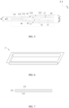
FIG. 6 is a schematic diagram of a packaging film of a packaging bag of a secondary battery provided in a first embodiment of the present application; -
FIG. 7 is a sectional view of the packaging film ofFIG. 6 . -
FIG. 8 is a schematic diagram of a secondary battery provided in a first embodiment of the present application before molding; -
FIG. 9 is an enlarged view of a block part ofFIG. 8 ; -
FIG. 10 is a schematic diagram of a secondary battery provided in a first embodiment of the present application in a molding process; -
FIG. 11 is another schematic diagram of a secondary battery provided in a first embodiment of the present application in a molding process; -
FIG. 12 is a schematic diagram of an electrode lead of a secondary battery provided in a first embodiment of the present application; -
FIG. 13 is a schematic diagram of a secondary battery provided in a second embodiment of the present application; and -
FIG. 14 is a schematic diagram of a secondary battery provided in a third embodiment of the present application. -
- 1 electrode assembly
- 2 packaging bag
- 21 sealing portion
- 211 main body region
- 212 first step region
- 213 second step region
- 214 first transition region
- 215 second transition region
- 22 packaging film
- 221 protective layer
- 222 metal layer
- 223 connecting layer
- 21 sealing portion
- 3 electrode lead
- 31 base portion
- 32 edge portion
- 4 insulating member
- 41 first part
- 42 second part
- 43 third part
- 44 fourth part
- 5 encapsulating device
- 51 first encapsulating surface
- 52 second encapsulating surface
- 53 third encapsulating surface
- 6 colloid
- X length direction
- Y width direction
- Z thickness direction
- To make the objectives, technical solutions, and advantages of the present application clearer and more comprehensible, the present application will be further described below in detail with reference to the accompanying drawings and embodiments. It should be understood that the specific embodiments described herein are merely used to explain the present application, but are not intended to limit the present application.
- In the description of the present application, unless otherwise specified and limited explicitly, the terms "first", "second", "third" and "fourth" are merely intended for a purpose of description, and shall not be understood as an indication or implication of relative importance. The term "a plurality of" refers to more than two (including two). Unless otherwise specified or illustrated, the term "connection" should be understood broadly, for example, the "connection" may either be a fixed connection, or a detachable connection, or an integrated connection, or an electrical connection, or a signal connection; and the "connection" may either be a direct connection, or an indirect connection through an intermediary. Those of ordinary skill in the art may appreciate the specific meanings of the foregoing terms in the present application according to specific conditions.
- In the description of the specification, it should be understood that the terms representing directions such as "up" and "down" described in the embodiments of the present application are described from the angles shown in the accompanying drawings, and should not be understood as limitation on the embodiments of the present application. The present application will be further described below in detail through the specific embodiments with reference to the accompanying drawings.
- With reference to
FIG. 1 and FIG. 2 , in a first embodiment, a secondary battery provided in the present application includes an electrode assembly 1, apackaging bag 2, anelectrode lead 3 and an insulatingmember 4. - The electrode assembly 1 is a core member of the secondary battery for achieving charging and discharging functions. The electrode assembly 1 includes a positive electrode sheet, a negative electrode sheet and a diaphragm, and the diaphragm isolates the positive electrode sheet from the negative electrode sheet. The positive electrode sheet includes a positive electrode current collector and a positive active material layer coated on a surface of the positive electrode current collector, the positive electrode current collector may be aluminum foil, and the positive active material layer includes a ternary material, lithium manganate or lithium iron phosphate. The negative electrode sheet includes a negative electrode current collector and a negative active material layer coated on a surface of the negative electrode current collector, the negative electrode current collector may be copper foil, and the negative active material layer includes graphite or silicon.
- The electrode assembly 1 may be in a winding structure. Specifically, there is one positive electrode sheet and one negative electrode sheet, and the positive electrode sheet and the negative electrode sheet are in banded structures. The positive electrode sheet, the diaphragm and the negative electrode sheet are stacked in sequence and wound more than two turns to form the electrode assembly 1. When the electrode assembly 1 is produced, the electrode assembly 1 may be wound into a hollow cylindrical structure first, and then flattened into a flat shape after the winding.
- Alternatively, the electrode assembly 1 may also be in a laminated structure. Specifically, the positive electrode sheet is set in plurality, the negative electrode sheet is set in plurality, the plurality of positive electrode sheets and the plurality of negative electrode sheets are stacked alternately in a thickness direction Z, and the diaphragm isolates the positive electrode sheet from the negative electrode sheet.
- The
packaging bag 2 includes twopackaging films 22, and the twopackaging films 22 are arranged up and down in the thickness direction Z. With reference toFIG. 6 , at least onepackaging film 22 is stamped to form a concave chamber, and the electrode assembly 1 is located between the twopackaging films 22 and housed in the concave chamber. - With reference to
FIG. 7 , eachpackaging film 22 includes aprotective layer 221, ametal layer 222 and a connectinglayer 223, and theprotective layer 221 and the connectinglayer 223 are respectively disposed on two sides of themetal layer 222. Specifically, theprotective layer 221 may be fixed to a surface of themetal layer 222 away from the electrode assembly 1 through a binder, and the connectinglayer 223 may be fixed to a surface of themetal layer 222 close to the electrode assembly 1 through the binder. A thickness of thepackaging film 22 may be 0.1 mm-0.3 mm. - A material of the
protective layer 221 may be nylon or polyethylene glycol terephthalate, a material of themetal layer 222 may be aluminum foil or steel foil, and a material of the connectinglayer 223 may be polypropylene. - The two
packaging films 22 are connected at edges to form a sealingportion 21. Specifically, by thermal compression, connectinglayers 223 of the twopackaging films 22 are directly or indirectly connected together, thereby forming a sealedpackaging bag 2. - The
electrode lead 3 is connected to the electrode assembly 1, passes through the sealingportion 21 and extends to an outside of thepackaging bag 2. Specifically, there may be two electrode leads 3, oneelectrode lead 3 is connected to the positive electrode current collector of the positive electrode sheet, and theother electrode lead 3 is connected to the negative electrode current collector of the negative electrode sheet. The two electrode leads 3 connect the electrode assembly 1 and other members outside thepackaging bag 2, and then charging and discharging of the electrode assembly 1 are achieved. A material of theelectrode lead 3 may be aluminum, nickel or copper plated with nickel. - The two electrode leads 3 may respectively extend from two ends of the
packaging bag 2 in a length direction X, or extend from the same end of thepackaging bag 2 in the length direction X. - There may be two insulating
members 4. The twoinsulating members 4 respectively isolate the two electrode leads 3 from the sealingportion 21. Each insulatingmember 4 surrounds an outer side of acorresponding electrode lead 3. A part of the insulatingmember 4 is clamped between the twopackaging films 22, thereby isolating theelectrode lead 3 from thepackaging films 22 and reducing a risk of contact of theelectrode lead 3 with themetal layer 222. A material of the insulatingmember 4 may be polypropylene. - Since a part of the insulating
member 4 is clamped between the twopackaging films 22, when thermal compression is performed on the twopackaging films 22, the connectinglayers 223 of the twopackaging films 22 are fused to the insulatingmember 4. - Specifically, with reference to
FIG. 4 andFIG. 5 , the sealingportion 21 includes amain body region 211, sfirst step region 212 and afirst transition region 214. Thefirst step region 212 is located on two sides of theelectrode lead 3 in the thickness direction Z, themain body region 211 and thefirst transition region 214 are located on a same side of thefirst step region 212 in a width direction Y, and thefirst transition region 214 is connected between thefirst step region 212 and themain body region 211. - The insulating
member 4 includes afirst part 41, and in the thickness direction Z, thefirst part 41 is located between theelectrode lead 3 and thefirst step region 212 and covers theelectrode lead 3 from two sides. Thefirst step region 212 is divided into upper and lower layers, and thefirst part 41 is located between the two layers of thefirst step region 212. - In the
first step region 212, the connectinglayer 223 of eachpackaging film 222 is fused to thefirst part 41. In the thickness direction Z, a sum of thicknesses of thefirst step region 212, thefirst part 41 and theelectrode lead 3 is H1. H1 is generally a constant value. Certainly, due to a thermal compression process, H1 may fluctuate within a certain range, for example, by plus or minus 0.01 mm. - In the
main body region 211, the connectinglayers 223 of the twopackaging films 22 are directly fused into one body. In the thickness direction Z, a thickness of themain body region 211 is H2. H2 is generally a constant value. Certainly, due to the thermal compression process, the thickness H2 of themain body region 211 may fluctuate within a certain range, for example, by plus or minus 0.01 mm. A value of H2 may be 0.2 mm-0.4 mm. - In the
main body region 211, the twopackaging films 22 are directly fused together; and in thefirst step region 212, the twopackaging films 22 and the first part of the insulatingmember 4 are fused together. Therefore, the value of H2 is less than a value of H1, and there is a difference in height between themain body region 211 and thefirst step region 212. Thefirst transition region 214 connected between themain body region 211 and thefirst step region 212 may play a role of transition. - To achieve fusion of the
main body region 211 and fusion of thefirst step region 212, anencapsulating device 5 having stepped encapsulating surfaces is usually used. Specifically, with reference toFIG. 8 and FIG. 9 , the encapsulatingdevice 5 includes afirst encapsulating surface 51 and asecond encapsulating surface 52, and thesecond encapsulating surface 52 is recessed relative to the first encapsulatingsurface 51. In the thermal compression, the first encapsulatingsurface 51 acts on themain body region 211, and thesecond encapsulating surface 52 acts on thefirst step region 212. - With reference to
FIG. 10 and FIG. 11 , in the process of thermal compression, thefirst part 41 and the connectinglayer 223 located in thefirst step region 212 are heated to melt and generate anadhesive colloid 6, part of the colloid 6 flows to a gap of thefirst transition region 214 under the action of pressure, and thecolloid 6 fills the gap and bonds the connectinglayer 223 located in thefirst transition region 214 together, thereby achieving sealing. - However, in the process of thermal compression, stress concentration occurs easily at an end part of the
electrode lead 3, and at the same time, thefirst part 41 is compressed thinly. If thefirst part 41 is too thin, stress at the end part of theelectrode lead 3 easily punctures thefirst part 41, even the sealingportion 21, which results in that an electrolyte corrodes themetal layer 222 in the sealingportion 21, thereby reducing sealing performance of thepackaging bag 2. In addition, when theelectrode lead 3 is in contact with themetal layer 222 of the sealingportion 21, a risk of a short circuit is easily caused. - With reference to
FIG. 5 , a minimum distance between theelectrode lead 3 and an outer surface of thefirst step region 212 is D2. Theelectrode lead 3 is generally a thin sheet parallel to the length direction X, and thus in a plane perpendicular to the length direction X, a distance between theelectrode lead 3 and the outer surface of thefirst step region 212 is minimum. Since thefirst step region 212 is generally a thin sheet perpendicular to the thickness direction Z, D2 is generally the minimum distance between theelectrode lead 3 and the outer surface of thefirst step region 212 in the thickness direction Z. The smaller a value of D2 is, and the easier thefirst step region 212 is to be punctured by theelectrode lead 3. The value of D2 may be changed by controlling a compression rate of thefirst part 41 in the thermal compression. Therefore, according to the embodiment of the present application, the value of D2 can satisfy a certain range according to needs, for example, be greater than 150 µm, to avoid puncturing thefirst step region 212 by theelectrode lead 3. - A minimum distance between the
electrode lead 3 and an outer surface of thefirst transition region 214 is Di. Similarly, theelectrode lead 3 is generally a thin sheet parallel to the length direction X, and thus in the plane perpendicular to the length direction X, a distance between theelectrode lead 3 and the outer surface of thefirst transition region 214 is minimum. Since thefirst transition region 214 is located on one side of thefirst step region 212 in the width direction Y, a distance between an end port of theelectrode lead 3 in the width direction Y and the outer surface of thefirst transition region 214 is minimum. Similarly, the smaller a value of Di is, and the easier the first transition region is to be punctured by theelectrode lead 3. - However, since there is the difference in height between the
main body region 211 and thefirst step region 212, in the process of thermal compression, thefirst transition region 214 is inclined toward a direction close to themain body region 211 and the electrode leads 3; and at the same time, thefirst transition region 214 is stretched. After thefirst transition region 214 is stretched, its thickness and strength both become smaller. If the value of Di is smaller than the value of D2, thefirst transition region 214 is easily punctured by the end part of theelectrode lead 3, thereby reducing the sealing performance of thepackaging bag 2 and causing a risk of a short circuit. Therefore, according to the embodiment of the present application, preferably, Di ≥ D2, to reduce a risk of puncturing thepackaging bag 2 and improve safety performance. - The
first transition region 214 connects themain body region 211 and thefirst step region 212, thefirst transition region 214 has two outer surfaces disposed oppositely in the thickness direction Z, and the two outer surfaces are inclined toward a direction close to thefirst step region 212 relative to themain body region 211. The outer surface of thefirst transition region 214 connects an outer surface of themain body region 211 and the outer surface of thefirst step region 212. The outer surface of thefirst transition region 214 may extend from an end part of the outer surface of thefirst step region 212, and is inclined toward a direction close to the outer surface of themain body region 211 relative to the outer surface of thefirst step region 212. In the thickness direction Z, spacing between the two outer surfaces of thefirst transition region 214 is L. In a direction in which themain body region 211 points to theelectrode lead 3, a value of L gradually increases. - With reference to
FIG. 5 , an included angle α between an outer surface of thefirst transition region 214 and the outer surface of thefirst step region 212 is 100°~170°. The smaller a value of α is, and the closer a distance between thefirst transition region 214 and the end part of theelectrode lead 3 is. That is, the less the value of Di may be, and the higher a risk of puncturing thefirst transition region 214 by theelectrode lead 3 is. Therefore, preferably, the value of α is not less than 100°. When the values of H1 and H2 are constant, the greater the value of α is, the more gentle the outer surface of thefirst transition region 214 is, and correspondingly, the larger a size of thefirst transition region 214 in the width direction Y is. Since a size of the secondary battery in the width direction Y is limited, the larger space occupied by thefirst transition region 214 in the width direction Y is, and the smaller space that other members (such as the electrode lead 3) can use is. Therefore, to avoid occupying too much space by thefirst transition region 214, the value of α is not greater than 170°. - With reference to
FIG. 5 andFIG. 12 , theelectrode lead 3 includes abase portion 31 and anedge portion 32, theedge portion 32 is connected to thebase portion 31 and located on one side of thebase portion 31 close to thefirst transition region 214 in the width direction Y, Compared with thebase portion 31, theedge portion 32 is closer to thefirst transition region 214. Further, a distance between one end of theedge portion 32 away from thebase portion 31 and thefirst transition region 214 is minimum. - The value of Di is determined by spacing between the
edge portion 32 and thefirst transition region 214 in the width direction Y and spacing between theedge portion 32 and thefirst transition region 214 in the thickness direction Z. To increase the value of D1, according to the embodiment of the present application, a thickness of theedge portion 32 is reduced. In addition, to reduce stress at a connection of theedge portion 32 and thebase portion 32 and achieve smooth transition, preferably, in a direction away from thebase portion 31, the thickness of theedge portion 32 gradually reduces. - The
edge portion 32 has a first surface facing thefirst step region 212, and the first surface is connected to thefirst part 41. Since the thickness of theedge portion 32 gradually reduces, the first surface is inclined relative to a reference plane perpendicular to the thickness direction Z. There are two first surfaces, and the two first surfaces face each other in the thickness direction Z. - The
base portion 31 has a second surface facing thefirst step region 212, and the second surface is connected to thefirst part 41. The second surface is a plane generally perpendicular to the thickness direction Z. There are two second surfaces, and the two second surfaces face each other in the thickness direction Z. - Preferably, with reference to
FIG. 12 , the first surface is connected to the second surface, and an included angle β between the two is greater than or equal to 120°. An edge is formed at a connection of the first surface and the second surface, and stress concentration occurs easily at the edge. If a value of β is too small, the edge is shaper, and a risk of puncturing thefirst part 41 and thefirst step region 212 in the thermal compression is higher. Therefore, to reduce the risk of puncturing thefirst part 41 and thefirst step region 212, β is preferably greater than 120°. - With reference to
FIG. 12 , an area of a section of theelectrode lead 3 perpendicular to the length direction X determines a current flow capacity of theelectrode lead 3. If the thickness of theedge portion 32 is too small, it will result in an insufficient current flow capacity of theelectrode lead 3. Meanwhile, when the thickness of theedge portion 32 is too small, strength of theelectrode lead 3 will be relatively small, and theelectrode lead 3 easily deforms. Therefore, to ensure a current flow area and the strength of theelectrode lead 3, a minimum thickness H5 of theedge portion 32 is greater than 100 µm. - In the width direction Y, a ratio of a size of the
edge portion 32 to a size of thebase portion 31 is 0.1-0.4. The thickness of theedge portion 32 is small, and a current flow capacity and strength of theedge portion 32 are both smaller than that of thebase portion 31. If the ratio is greater than 0.4, the size of theedge portion 32 is larger, which will results in an insufficient overall current flow area and weak strength of theelectrode lead 3. When the thickness of thebase portion 31 and the minimum thickness of theedge portion 32 are constant, the smaller the size of theedge portion 32 in the width direction Y is, and the greater the value of β is. Therefore, if the ratio is less than 0.1, it will result in a too great value of β, and the risk of puncturing thefirst part 41 and thefirst step region 212 is higher. Therefore, preferably, in the width direction Y, the ratio of the size of theedge portion 32 to the size of thebase portion 31 is 0.1-0.4. - In the width direction Y, a size of the
first step region 212 is greater than a size of theelectrode lead 3. Preferably, thefirst step region 212 is beyond theelectrode lead 3 in the width direction Y. In other words, one end of thefirst step region 212 close to themain body region 211 in the width direction Y is beyond theelectrode lead 3, and one end of thefirst step region 212 away from themain body region 211 in the width direction Y is also beyond theelectrode lead 3. - In the embodiment of the present application, by increasing the size of the
first step region 212 in the width direction Y, a distance between thefirst transition region 214 and theedge portion 32 in the width direction Y can be increased, thereby increasing the value of Di and reducing a safety risk. - The insulating
member 4 further includes asecond part 42, thesecond part 42 is connection to thefirst part 41, and a part of thefirst step region 212 beyond theelectrode lead 3 covers thesecond part 42 from two sides. Thefirst part 41 is divided into upper and lower layers by theelectrode lead 3, and thesecond part 42 connects the two layers of thefirst part 41 together. A sum of thicknesses of thesecond part 42 and thefirst step region 212 is H3. Before the thermal compression, values of H3 and H1 are generally the same, but theelectrode lead 3 is made of metal and is not easily compressed, and thus the value of H3 may be slightly less than the value of H1 after the thermal compression. - The sealing
portion 21 includes asecond step region 213, and thesecond step region 213 connects themain body region 211 and thefirst transition region 214. In the width direction Y, thesecond step region 213 is located between themain body region 211 and thefirst transition region 214. The insulatingmember 4 further includes athird part 43 and afourth part 44, thethird part 43 extends from an end of thesecond part 42 away from theelectrode lead 3, and thefourth part 44 extends from an end of thethird part 43 away from thesecond part 42. in the thickness direction Z, thefirst transition region 214 covers thethird part 43 from two sides, and thesecond step region 213 covers thefourth part 44 from two sides. - In the
first transition region 214, the connectinglayers 223 of the twopackaging films 22 are fused to thethird part 43; and in thesecond step region 213, the connectinglayers 223 of the twopackaging films 22 are fused to thefourth part 44. - A sum of thicknesses of the
second step region 213 and thefourth part 44 is H4, and H2 < H4 < H1. H4 is generally a constant value. Certainly, due to the thermal compression process, H1 may fluctuate within a certain range, for example, by plus or minus 0.01 mm. A value of H4 may be 0.3 mm-0.9 mm. - In the
first step region 212, thefirst part 41 and theelectrode lead 3 are disposed between the twopackaging films 22, and thus H2 and H1 have a greater difference value. In the thermal compression, a degree of stretching thefirst transition region 214 is great, which results in damage to themetal layer 222 located in thefirst transition region 214 and affects sealing performance. To reduce the degree of stretching thefirst transition region 214, according to the embodiment of the present application, thesecond step region 213 is preferably provided. Thesecond step region 213 can play a role of transition, and a difference in height between thesecond step region 213 and themain body area 211 and a difference in height between thesecond step region 213 and thefirst step region 212 are reduced, thereby reducing the degree of stretching thefirst transition region 214, reducing stress concentration, and improving the sealing performance. - When the value of H1 is constant, the value of α can be increased by increasing the value of H4, thereby increasing the value of Di. Similarly, the value of Di can also be increased by reducing the value of H5. That is, both the value of H4 and the value of H5 have a direct influence on the value of D1. The applicant comprehensively considers H4 and H5, and preferably, H5 < H4. In this case, it can be ensured that the
edge portion 32 and thefirst transition region 214 are spaced by a sufficient distance in the vertical direction Z, and the value of Di is increased, thereby improving the sealing performance. - Since the
first transition region 214 is disposed obliquely, to ensure that thethird part 43 can be attached to thefirst transition region 214 and avoid that thethird part 43 blocks deformation of thefirst transition region 214 in the thermal compression process, thethird part 43 needs to have an inclined surface. In other words, in a direction in which thesecond part 42 points to thefourth part 44, a thickness of thethird part 43 gradually reduces. A minimum thickness of thethird part 43 is equal to a thickness of thefourth part 44, and a maximum thickness of thethird part 43 is equal to a thickness of thesecond part 42. - To thermally compress the
second step region 213, the encapsulatingdevice 5 further includes athird encapsulating surface 53. Thethird encapsulating surface 53 is located between the first encapsulatingsurface 51 and thesecond encapsulating surface 52; and relative to the first encapsulatingsurface 51, a degree of recessing of thethird encapsulating surface 53 is smaller than a degree of recessing of thesecond encapsulating surface 52. - Preferably, the sealing
portion 21 further includes asecond transition region 215, and thesecond transition region 215 is connected between themain body region 211 and thesecond step region 213. With reference toFIG. 10 , due to process errors, in the thermal compression, there may be a certain distance between themain body region 211 and thefourth part 44, which results in that thesecond transition region 215 is unable to be attached to thefourth part 44. In this case, in thesecond transition region 215, a gap is left between the twopackaging films 22. In addition, in the thermal compression, thesecond transition region 215 is in an inclined state and is not subject to the pressure of thethird encapsulating surface 53. Therefore, in thesecond transition region 215, the connectinglayers 223 of the twopackaging films 22 are unable to be directly fused together. - With reference to
FIG. 11 , in the process of thermal compression, thefourth part 44 and the connectinglayer 223 located in thesecond step region 213 are heated to melt and generate anadhesive colloid 6, part of the colloid 6 flows to a gap of thesecond transition region 215 under the action of pressure, and thecolloid 6 fills the gap and bonds the connectinglayer 223 located in thesecond transition region 215 together, thereby achieving sealing. - Other embodiments of the secondary battery provided in the embodiment of the present application will be described below. To simplify the description, only differences between the other embodiments and the first embodiment will be mainly introduced below, and the parts not described can be understood with reference to the first embodiment.
- With reference to 13, in a second embodiment, the
second step region 213 may be omitted. According to the embodiment of the present application, the value of Di can be increased by increasing the size of thefirst step region 212 in the width direction Y and providing thesecond part 42. The increase of the value of D1 can reduce the risk of puncturing thepackaging bag 2 and improve safety performance. - With reference to
FIG. 14 , in a third embodiment, the size of theelectrode lead 3 in the width direction Y may be equal to or greater than the size of thefirst step region 212. In this case, thesecond part 42 is omitted. According to the embodiment of the present application, the value of Di is increased by reducing the thickness of theedge portion 32, thereby reducing the risk of puncturing thepackaging bag 2 and improving safety performance. Certainly, compared with embodiment one, to make the value of Di meet requirements, theedge portion 32 in the third embodiment needs to have a smaller thickness.
Claims (11)
- Secondary battery, comprising an electrode assembly (1), a packaging bag (2), an electrode lead (3) and an insulating member (4);wherein the electrode assembly (1) is housed in the packaging bag (2), an edge of the packaging bag (2) has a sealing portion (21), and the electrode lead (3) is connected to the electrode assembly (1) and passes through the sealing portion (21);the sealing portion (21) comprises a main body region (211), a first step region (212) and a first transition region (214), the first step region (212) is located on two sides of the electrode lead (3) in a thickness direction (Z), the main body region (211) and the first transition region (214) are located on a same side of the first step region (212) in a width direction (Y), and the first transition region (214) is connected between the first step region (212) and the main body region (211);the insulating member (4) surrounds an outer side of the electrode lead (3) and isolates the sealing portion (21) from the electrode lead (3); the insulating member (4) comprises a first part (41), and in the thickness direction (Z), the first part (41) is located between the electrode lead (3) and the first step region (212) and covers the electrode lead (3) from two sides;a sum of thicknesses of the first step region (212), the first part (41) and the electrode lead (3) is H1, a thickness of the main body region (211) is H2, and H1 > H2; anda minimum distance between the electrode lead (3) and an outer surface of the first transition region (214) is Di and a distance between an end port of the electrode lead (3) in the width direction (Y) and the outer surface of the first transition region (214) is minimum, a minimum distance between the electrode lead (3) and an outer surface of the first step region (212) is D2, and D1 ≥ D2;wherein the first transition region (214) connects the main body region (211) and the first step region (212), the first transition region (214) has two outer surfaces disposed oppositely in the thickness direction (Z), the two outer surfaces are inclined toward a direction close to the first step region (212) relative to the main body region (211) and the outer surfaces of the first transition region (214) extend from an end part of the outer surfaces of the first step region (212), and are inclined toward a direction close to the outer surfaces of the main body region (211) relative to the outer surfaces of the first step region (212);wherein an included angle between an outer surface of the first transition region (214) and the outer surface of the first step region (212) is 100°~170°;wherein the electrode lead (3) comprises a base portion (31) and an edge portion (32), the edge portion (32) is connected to the base portion (31) and located on one side of the base portion (31) close to the first transition region (214) in the width direction (Y); andin a direction away from the base portion (31), a thickness of the edge portion (32) gradually reduces;and wherein in the width direction (Y), the first step region (212) is beyond the electrode lead (3); and the insulating member (4) further comprises a second part (42), the second part (42) is connection to the first part (41), and a part of the first step region (212) beyond the electrode lead (3) covers the second part (42) from two sides;wherein in the plane perpendicular to a length direction (X), a distance between the electrode lead (3) and the outer surface of the first transition region (214) is minimum; and wherein since the first transition region (214) is located on one side of the first step region (212) in the width direction (Y), a distance between an end port of the electrode lead (3) in the width direction (Y) and the outer surface of the first transition region (214) is minimum.
- Secondary battery according to claim 1, wherein the edge portion (32) has a first surface facing the first step region (212), the base portion (31) has a second surface facing the first step region (212), the first surface is connected to the second surface, and an included angle between the two is greater than or equal to 120°.
- Secondary battery according to claim 1 or 2, wherein a minimum thickness of the edge portion (32) is greater than 100 µm.
- Secondary battery according to claim 1, wherein in the width direction (Y), a ratio of a size of the edge portion (32) to a size of the base portion (31) is 0.1-0.4.
- Secondary battery according to claim 1, wherein the sealing portion (21) comprises a second step region (213), and the second step region (213) connects the main body region (211) and the first transition region (214);the insulating member (4) further comprises a third part (43) and a fourth part (44), the third part (43) extends from an end of the second part (42) away from the electrode lead (3), and the fourth part (44) extends from an end of the third part (43) away from the second part (42);in the thickness direction, the first transition region (214) covers the third part (43) from two sides, and the second step region (213) covers the fourth part (44) from two sides; anda sum of thicknesses of the second step region (213) and the fourth part (44) is H4, and H2 < H4 < H1.
- Secondary battery according to claim 5, wherein a minimum thickness of the edge portion (32) is H5, and H5 < H4.
- Secondary battery according to claim 5, wherein in a direction in which the second part (42) points to the fourth part (44), a thickness of the third part (43) gradually reduces.
- Secondary battery according to claim 1, wherein a value of D2 is greater than 150 µm.
- Secondary battery according to any one of claims 1-8, whereinthe packaging bag (2) comprises two packaging films (22), the electrode assembly (1) is located between the two packaging films (22), and the two packaging films (22) are connected at edges to form the sealing portion (21);each packaging film (22) comprises a protective layer (221), a metal layer (222) and a connecting layer (223), the connecting layer (223) is disposed on a surface of the metal layer (222) facing the electrode assembly (1), and the protective layer (221) is disposed on a surface of the metal layer (222) away from the electrode assembly (1);in the main body region (211), connecting layers (223) of the two packaging films (22) are welded into one body; and in the first step region (212), the connecting layer (223) of each packaging film (222) is welded to the first part (41).
- Secondary battery according to any one of claims 1 -9, wherein the electrode assembly (1) is in a winding structure or in a laminated structure.
- Secondary battery according to claim 9, wherein a thickness of the packaging film 22 is 0.1 mm-0.3 mm.
Applications Claiming Priority (3)
| Application Number | Priority Date | Filing Date | Title |
|---|---|---|---|
| CN201910413559.XA CN110190316B (en) | 2019-05-17 | 2019-05-17 | Secondary battery |
| EP20809904.4A EP3800690B1 (en) | 2019-05-17 | 2020-04-11 | Secondary battery |
| PCT/CN2020/084343 WO2020233276A1 (en) | 2019-05-17 | 2020-04-11 | Secondary battery |
Related Parent Applications (2)
| Application Number | Title | Priority Date | Filing Date |
|---|---|---|---|
| EP20809904.4A Division-Into EP3800690B1 (en) | 2019-05-17 | 2020-04-11 | Secondary battery |
| EP20809904.4A Division EP3800690B1 (en) | 2019-05-17 | 2020-04-11 | Secondary battery |
Publications (2)
| Publication Number | Publication Date |
|---|---|
| EP4231403A2 true EP4231403A2 (en) | 2023-08-23 |
| EP4231403A3 EP4231403A3 (en) | 2024-05-29 |
Family
ID=67716686
Family Applications (2)
| Application Number | Title | Priority Date | Filing Date |
|---|---|---|---|
| EP20809904.4A Active EP3800690B1 (en) | 2019-05-17 | 2020-04-11 | Secondary battery |
| EP23174763.5A Pending EP4231403A3 (en) | 2019-05-17 | 2020-04-11 | Secondary battery |
Family Applications Before (1)
| Application Number | Title | Priority Date | Filing Date |
|---|---|---|---|
| EP20809904.4A Active EP3800690B1 (en) | 2019-05-17 | 2020-04-11 | Secondary battery |
Country Status (6)
| Country | Link |
|---|---|
| US (2) | US12021268B2 (en) |
| EP (2) | EP3800690B1 (en) |
| CN (2) | CN111952655B (en) |
| HU (1) | HUE062873T2 (en) |
| PL (1) | PL3800690T3 (en) |
| WO (1) | WO2020233276A1 (en) |
Families Citing this family (5)
| Publication number | Priority date | Publication date | Assignee | Title |
|---|---|---|---|---|
| CN111952655B (en) * | 2019-05-17 | 2024-01-26 | 宁德时代新能源科技股份有限公司 | Secondary battery |
| CN113422161A (en) * | 2021-06-09 | 2021-09-21 | 宁德新能源科技有限公司 | Electrochemical device and electronic device |
| CN113488726B (en) * | 2021-07-14 | 2024-06-04 | 宁德新能源科技有限公司 | Electrochemical device, battery pack, power consumption device and packaging device |
| CN113871808B (en) * | 2021-10-25 | 2024-03-26 | 珠海冠宇电池股份有限公司 | Soft package lithium ion battery and electronic device |
| CN118251664A (en) * | 2022-11-17 | 2024-06-25 | 宁德新能源科技有限公司 | Electrochemical device, electronic apparatus, and method for manufacturing electrochemical device |
Family Cites Families (25)
| Publication number | Priority date | Publication date | Assignee | Title |
|---|---|---|---|---|
| KR20050098318A (en) * | 2004-04-06 | 2005-10-12 | 삼성에스디아이 주식회사 | Electrodes assembly and secondary battery using the same |
| JP4736525B2 (en) * | 2005-05-02 | 2011-07-27 | ソニー株式会社 | Nonaqueous electrolyte secondary battery |
| KR101096894B1 (en) * | 2005-05-12 | 2011-12-21 | 에스케이이노베이션 주식회사 | Li secondary battery for improving bondability of tab to polymer film |
| KR20080006103A (en) * | 2006-07-11 | 2008-01-16 | 삼성에스디아이 주식회사 | Pouch type rechargeable battery |
| CN102208594B (en) * | 2010-03-30 | 2015-04-29 | 三星Sdi株式会社 | Secondary battery |
| JP5439317B2 (en) * | 2010-08-30 | 2014-03-12 | 日立ビークルエナジー株式会社 | Secondary battery |
| US8709645B2 (en) * | 2011-07-01 | 2014-04-29 | Apple Inc. | Battery pouch sheet edge insulation |
| JP5959878B2 (en) * | 2012-02-21 | 2016-08-02 | 藤森工業株式会社 | Nonaqueous battery storage container provided with electrode lead wire member |
| KR20140064406A (en) * | 2012-11-20 | 2014-05-28 | 주식회사 엘지화학 | Battery cell having folding grooves |
| JP6111476B2 (en) * | 2012-12-24 | 2017-04-12 | エルジー・ケム・リミテッド | Pouch-type secondary battery with seal margin for improved durability |
| JP2014026980A (en) * | 2013-09-17 | 2014-02-06 | Showa Denko Packaging Co Ltd | Electrochemical device |
| KR20160002176A (en) * | 2014-06-30 | 2016-01-07 | 주식회사 엘지화학 | Secondary battery |
| CN204464336U (en) * | 2015-02-13 | 2015-07-08 | 宁德新能源科技有限公司 | The end enclosure structure of flexible-packed battery |
| JP6606834B2 (en) * | 2015-03-05 | 2019-11-20 | 株式会社Gsユアサ | Storage element and lead terminal |
| JP6736264B2 (en) * | 2015-05-29 | 2020-08-05 | 株式会社東芝 | Secondary battery |
| KR101809208B1 (en) * | 2015-06-16 | 2017-12-14 | 주식회사 엘지화학 | Secondary battery and method for fabricating the same |
| KR101984265B1 (en) * | 2015-07-03 | 2019-05-30 | 주식회사 엘지화학 | Pouch type secondary battery and method of fabricating the same |
| KR20170117674A (en) * | 2016-04-14 | 2017-10-24 | 주식회사 엘지화학 | Battery Cell Comprising Electrode Lead Coated with Thin Film Layer for Sealing |
| WO2018049561A1 (en) * | 2016-09-13 | 2018-03-22 | 东莞新能源科技有限公司 | Battery |
| US10446803B2 (en) * | 2017-08-29 | 2019-10-15 | Robert Bosch Battery Systems Llc | Lead tab for battery terminal |
| CN109671983B (en) * | 2017-10-16 | 2024-06-07 | 东莞新能德科技有限公司 | Battery cell |
| CN208507818U (en) * | 2018-06-29 | 2019-02-15 | 宁德时代新能源科技股份有限公司 | Secondary cell and its pole piece |
| CN209709099U (en) * | 2019-05-17 | 2019-11-29 | 宁德时代新能源科技股份有限公司 | Secondary cell |
| CN111952655B (en) * | 2019-05-17 | 2024-01-26 | 宁德时代新能源科技股份有限公司 | Secondary battery |
| CN110190206B (en) * | 2019-05-17 | 2020-10-02 | 宁德时代新能源科技股份有限公司 | Secondary battery |
-
2019
- 2019-05-17 CN CN202010801316.6A patent/CN111952655B/en active Active
- 2019-05-17 CN CN201910413559.XA patent/CN110190316B/en active Active
-
2020
- 2020-04-11 HU HUE20809904A patent/HUE062873T2/en unknown
- 2020-04-11 PL PL20809904.4T patent/PL3800690T3/en unknown
- 2020-04-11 WO PCT/CN2020/084343 patent/WO2020233276A1/en unknown
- 2020-04-11 EP EP20809904.4A patent/EP3800690B1/en active Active
- 2020-04-11 EP EP23174763.5A patent/EP4231403A3/en active Pending
- 2020-12-31 US US17/139,687 patent/US12021268B2/en active Active
-
2024
- 2024-05-15 US US18/664,283 patent/US20240304957A1/en active Pending
Also Published As
| Publication number | Publication date |
|---|---|
| EP3800690B1 (en) | 2023-07-12 |
| US20240304957A1 (en) | 2024-09-12 |
| EP3800690A4 (en) | 2021-09-22 |
| EP3800690A1 (en) | 2021-04-07 |
| US12021268B2 (en) | 2024-06-25 |
| CN110190316B (en) | 2024-05-10 |
| CN111952655A (en) | 2020-11-17 |
| EP4231403A3 (en) | 2024-05-29 |
| WO2020233276A1 (en) | 2020-11-26 |
| CN110190316A (en) | 2019-08-30 |
| HUE062873T2 (en) | 2023-12-28 |
| PL3800690T3 (en) | 2023-11-27 |
| US20210126324A1 (en) | 2021-04-29 |
| CN111952655B (en) | 2024-01-26 |
Similar Documents
| Publication | Publication Date | Title |
|---|---|---|
| EP4231403A2 (en) | Secondary battery | |
| US20210135321A1 (en) | Secondary battery, apparatus and manufacturing method for secondary battery | |
| US6558438B1 (en) | Method for producing a pressurized package for a film packed battery | |
| TWI399878B (en) | Sheet type battery and manufacturing method thereof | |
| US11245145B2 (en) | Secondary battery | |
| KR101192090B1 (en) | Lithium Secondary Battery | |
| EP3736879A1 (en) | Battery pack and vehicle | |
| US20100173194A1 (en) | Electric energy storage device and manufactruing method thereof | |
| EP2899771A1 (en) | Pouch-type secondary battery having sealing margin for improved durability | |
| KR101072681B1 (en) | Laminate secondary battery | |
| CN110190319B (en) | Electrode assembly and secondary battery | |
| KR20220057520A (en) | secondary battery | |
| KR20220018569A (en) | secondary battery | |
| CN209709099U (en) | Secondary cell | |
| CN110190206B (en) | Secondary battery | |
| CN211578910U (en) | Pole piece structure of ultrathin battery and ultrathin battery | |
| JP2010232076A (en) | Sheet-like secondary battery and manufacturing method therefor | |
| CN115380397A (en) | Battery assembly, battery using same and electronic device | |
| CN209880672U (en) | Secondary battery | |
| JP2000215879A (en) | Polymer electrolyte battery | |
| US11552354B2 (en) | Secondary battery | |
| JP2020053160A (en) | Power storage module | |
| US20220384882A1 (en) | Outer package and battery | |
| US20230081338A1 (en) | Jig for evaluating buffer pad, and method of evaluating buffer pad using the same | |
| WO2023245350A1 (en) | Electrochemical device and electric device |
Legal Events
| Date | Code | Title | Description |
|---|---|---|---|
| PUAI | Public reference made under article 153(3) epc to a published international application that has entered the european phase |
Free format text: ORIGINAL CODE: 0009012 |
|
| STAA | Information on the status of an ep patent application or granted ep patent |
Free format text: STATUS: REQUEST FOR EXAMINATION WAS MADE |
|
| 17P | Request for examination filed |
Effective date: 20230523 |
|
| AC | Divisional application: reference to earlier application |
Ref document number: 3800690 Country of ref document: EP Kind code of ref document: P |
|
| AK | Designated contracting states |
Kind code of ref document: A2 Designated state(s): AL AT BE BG CH CY CZ DE DK EE ES FI FR GB GR HR HU IE IS IT LI LT LU LV MC MK MT NL NO PL PT RO RS SE SI SK SM TR |
|
| PUAL | Search report despatched |
Free format text: ORIGINAL CODE: 0009013 |
|
| AK | Designated contracting states |
Kind code of ref document: A3 Designated state(s): AL AT BE BG CH CY CZ DE DK EE ES FI FR GB GR HR HU IE IS IT LI LT LU LV MC MK MT NL NO PL PT RO RS SE SI SK SM TR |
|
| RIC1 | Information provided on ipc code assigned before grant |
Ipc: H01M 50/184 20210101ALI20240419BHEP Ipc: H01M 50/178 20210101ALI20240419BHEP Ipc: H01M 50/129 20210101ALI20240419BHEP Ipc: H01M 50/105 20210101ALI20240419BHEP Ipc: H01M 10/0587 20100101ALI20240419BHEP Ipc: H01M 10/0585 20100101ALI20240419BHEP Ipc: H01M 10/0525 20100101AFI20240419BHEP |