EP4231264B1 - Modifikation von triggerschwellen von rfid-vorrichtungen in einem elektronischen artikelüberwachungssystem - Google Patents
Modifikation von triggerschwellen von rfid-vorrichtungen in einem elektronischen artikelüberwachungssystem Download PDFInfo
- Publication number
- EP4231264B1 EP4231264B1 EP23169909.1A EP23169909A EP4231264B1 EP 4231264 B1 EP4231264 B1 EP 4231264B1 EP 23169909 A EP23169909 A EP 23169909A EP 4231264 B1 EP4231264 B1 EP 4231264B1
- Authority
- EP
- European Patent Office
- Prior art keywords
- rfid
- inventory
- piece
- infrastructure
- zone
- Prior art date
- Legal status (The legal status is an assumption and is not a legal conclusion. Google has not performed a legal analysis and makes no representation as to the accuracy of the status listed.)
- Active
Links
Images

Classifications
-
- G—PHYSICS
- G08—SIGNALLING
- G08B—SIGNALLING SYSTEMS, e.g. PERSONAL CALLING SYSTEMS; ORDER TELEGRAPHS; ALARM SYSTEMS
- G08B13/00—Burglar, theft or intruder alarms
- G08B13/22—Electrical actuation
- G08B13/24—Electrical actuation by interference with electromagnetic field distribution
- G08B13/2402—Electronic Article Surveillance [EAS], i.e. systems using tags for detecting removal of a tagged item from a secure area, e.g. tags for detecting shoplifting
- G08B13/2405—Electronic Article Surveillance [EAS], i.e. systems using tags for detecting removal of a tagged item from a secure area, e.g. tags for detecting shoplifting characterised by the tag technology used
- G08B13/2414—Electronic Article Surveillance [EAS], i.e. systems using tags for detecting removal of a tagged item from a secure area, e.g. tags for detecting shoplifting characterised by the tag technology used using inductive tags
- G08B13/2417—Electronic Article Surveillance [EAS], i.e. systems using tags for detecting removal of a tagged item from a secure area, e.g. tags for detecting shoplifting characterised by the tag technology used using inductive tags having a radio frequency identification chip
-
- G—PHYSICS
- G08—SIGNALLING
- G08B—SIGNALLING SYSTEMS, e.g. PERSONAL CALLING SYSTEMS; ORDER TELEGRAPHS; ALARM SYSTEMS
- G08B13/00—Burglar, theft or intruder alarms
- G08B13/22—Electrical actuation
- G08B13/24—Electrical actuation by interference with electromagnetic field distribution
- G08B13/2402—Electronic Article Surveillance [EAS], i.e. systems using tags for detecting removal of a tagged item from a secure area, e.g. tags for detecting shoplifting
- G08B13/2465—Aspects related to the EAS system, e.g. system components other than tags
- G08B13/2482—EAS methods, e.g. description of flow chart of the detection procedure
-
- G—PHYSICS
- G08—SIGNALLING
- G08B—SIGNALLING SYSTEMS, e.g. PERSONAL CALLING SYSTEMS; ORDER TELEGRAPHS; ALARM SYSTEMS
- G08B29/00—Checking or monitoring of signalling or alarm systems; Prevention or correction of operating errors, e.g. preventing unauthorised operation
- G08B29/18—Prevention or correction of operating errors
- G08B29/20—Calibration, including self-calibrating arrangements
- G08B29/24—Self-calibration, e.g. compensating for environmental drift or ageing of components
- G08B29/26—Self-calibration, e.g. compensating for environmental drift or ageing of components by updating and storing reference thresholds
Definitions
- the present subject matter relates to radio frequency identification (“RFID”) devices. More particularly, the present subject matter relates to controlling the trigger thresholds of RFID devices used in an electronic article surveillance (“EAS”) system.
- RFID radio frequency identification
- EAS electronic article surveillance
- RFID tags and labels (which may be collectively referred to herein as "RFID devices") have been employed to perform both of these functions.
- An EAS system employing RFID technology typically has two primary read zones, each of which includes an associated RFID reader.
- One of the read zones is an area in the store where the products are presented to the consumer (which may be referred to herein as "inventory zone"), while the other read zone is an area at the exit of the store where any RFID devices that have not been suitably deactivated may be detected (which may be referred to herein as a “detection zone”) to trigger some type of alarm, indicating that an attempt is being made to steal the product(s).
- the cashier either removes or deactivates the RFID device associated with it. If the RFID device is not removed or deactivated, an RFID reader or readers will read the device and cause an alarm or other alert to trigger in the detection zone.
- US 2012/0044074 discloses methods and apparatus for detecting proximity of an electronic article surveillance (EAS)
- the disclosed EAS system comprises an RFID tag reader and a distinct EAS tag reader.
- US 2018/0350218 discloses retail systems to detect suspicious movement patterns within a retail shopping facility including an array of RFID readers and an array of camera systems.
- US 2017/0063476 discloses systems and methos for RFID security tags coupled to inventory items, comprising concurrently reading the RFID security tags and locator tags.
- an electronic article surveillance system includes a first read zone including an associated RFID reader, with a piece of infrastructure at least partially positioned within the first read zone.
- An RFID guard device is secured with respect to the piece of infrastructure.
- a second read zone of the systems includes an associated RFID reader configured to detect an RFID inventory device associated with a piece of inventory removably associated with the piece of infrastructure at a trigger threshold.
- the system also includes a controller configured to, when the RFID guard device is detected by the RFID reader, initiate a response selected from the group consisting of modifying the trigger threshold, modifying an amount of power transmitted by the RFID reader associated with the second read zone, modifying a direction in which power is transmitted by the RFID reader associated with the second read zone, and transmitting a signal indicative of a need to move the piece of infrastructure away from the second read zone.
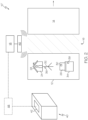
- Fig. 1 shows an EAS system 10 employing RFID technology according to an aspect of the present disclosure.
- the EAS system 10 of Fig. 1 has an inventory zone 12 and a detection zone 14, with a transition zone 16 separating the two read zones 12 and 14.
- the EAS system 10 further includes a controller 18, which is coupled to a first RFID reader 20 associated with the inventory zone 12 and a second RFID reader 22 associated with the detection zone 14.
- a plurality of pieces of inventory 24 and 26 are shown as being positioned within the inventory zone 12, with each piece of inventory 24, 26 having an associated RFID device 28, 30 (which may be referred to herein as an RFID inventory device).
- the pieces of inventory 24 and 26 may be differently configured, thereby differently affecting the performance of the associated RFID device 28, 30, as will be described in greater detail herein.
- the inventory zone 12 represents an area in the store where products are presented to the consumer
- the detection zone 14 represents an area at the exit of the store where any RFID inventory devices that have not been suitably deactivated may be detected to trigger some type of alarm, indicating that an attempt is being made to steal them.
- the cashier either removes or deactivates the RFID inventory device associated with it. If the RFID inventory device is not removed or deactivated, it will be detected in the detection zone 14, which causes an alarm or other alert to trigger and notify store personnel.
- each piece of inventory 24, 26 is shown in Fig. 1 as being removably associated with a piece of infrastructure 32, 34 configured to support and display the associated piece or pieces of inventory in the inventory zone 12.
- one of the pieces of infrastructure 32 is configured as a mannequin, while the other piece of infrastructure 34 is configured as a table, though it should be understood that pieces of infrastructure may be otherwise configured without departing from the scope of the present disclosure.
- each piece of infrastructure 32, 34 includes an associated RFID device 36, 38 (which may be referred to herein as an RFID guard device) that is secured with respect to the piece of infrastructure 32, 34 (e.g., by being affixed to the piece of infrastructure 32, 34).
- the RFID guard devices 36 and 38 are not configured to generate an alarm when they are detected in the detection zone 14, but may be used to reduce false alarms arising from the detection of an RFID inventory device in the detection zone 14, as will be described in greater detail.
- the EAS system 10 of Fig. 1 is shown as including an additional read zone 40, which is configured to receive pieces of inventory before they are moved into the inventory zone 12.
- This initial or preliminary read zone 40 is provided to determine the number of pieces of inventory in stock before the pieces of inventory are moved into the inventory zone 12 for display and consideration by customers.
- the initial or preliminary read zone 40 may be variously configured without departing from the scope of the present disclosure.
- the initial or preliminary read zone 40 is configured as an RFID read chamber, which includes an associated RFID reader 42 and is configured to receive a plurality of pieces of inventory and their associated RFID devices.
- An RFID read chamber may be relatively large (e.g., configured to accommodate a plurality of containers loaded on a pallet) or smaller (e.g., configured to accommodate a single container), depending on the needs and configuration of the store.
- the initial or preliminary read zone 40 (if provided) may be differently configured, such as being configured as an RFID-enabled gate through which inventory passes before reaching the inventory zone 12 or as a warehouse or storage area in which RFID inventory devices are detected or read by handheld RFID readers operated by store personnel, for example.
- Fig. 1 illustrates separate RFID readers 20 and 22 associated with the inventory zone 12 and the detection zone 14, it is within the scope of the present disclosure for a single RFID reader 46 to be associated with the two zones 12 and 14, as in the EAS system 10' shown in Fig. 2 .
- the inventory zone and/or the detection zone has a plurality of readers, e.g., 2, 3, 4, 5, or greater.
- the plurality of readers is controlled by a single controller.
- each of the readers is controlled by its own controller.
- the plurality of readers is controlled by more than one controller but the number of controllers is less than the number of readers, such that at least more than one reader is controlled by one controller.
- the transition zone 16 is ideally sized and configured such that RFID devices (especially RFID inventory devices) positioned in the inventory zone 12 are only detected by the RFID reader 20 associated with the inventory zone 12 and not by the RFID reader 22 associated with the detection zone 14 (or, in the case of the system 10' of Fig. 2 , only by a signal emitted by the RFID reader 18 into the inventory zone 12 and not into the detection zone 14).
- RFID devices especially RFID inventory devices
- the transition zone 16 is ideally sized and configured such that RFID devices (especially RFID inventory devices) positioned in the inventory zone 12 are only detected by the RFID reader 20 associated with the inventory zone 12 and not by the RFID reader 22 associated with the detection zone 14 (or, in the case of the system 10' of Fig. 2 , only by a signal emitted by the RFID reader 18 into the inventory zone 12 and not into the detection zone 14).
- RFID devices positioned in the detection zone 14 to be detected only in the detection zone 14 and not in the inventory zone 12. This may be achieved by providing a large transition zone 16, although such an approach reduces the
- the size of the transition zone 16 may be decreased by instead adjusting the level at which an RFID inventory device is detected in the detection zone 14 (which level may be referred to herein as the "trigger threshold"). While this aspect of the present disclosure is described in terms of adjustment of the trigger threshold of the detection zone 14 (to prevent false alarms when an RFID inventory device in the inventory zone 12 is detected in the detection zone 14), it should be understood that the trigger threshold of the inventory zone 12 may be similarly adjusted to prevent situations in which an RFID device in the detection zone 14 is detected in the inventory zone 12.
- an RFID inventory device may include a sensor that records a particular value that may be transmitted to the controller 18 of the EAS system 10, 10'.
- the controller 18 may determine whether to adjust the trigger threshold for the RFID inventory device in which the sensor is associated, which may include decreasing the trigger threshold (e.g., if the value indicates that the piece of inventory associated with the RFID inventory device is at risk of being stolen) or increasing the trigger threshold (e.g., if the value indicates that the piece of inventory associated with the RFID inventory device is not at risk of being stolen).
- the various RFID inventory devices may each be programmed with a unique identity to allow the controller 18 to assign an appropriate trigger threshold to the proper RFID inventory device.
- the sensor may be variously configured without departing from the scope of the present disclosure.
- the value of the sensor is a capacitance.
- Such a sensor may be particularly useful for an auto-tunable RFID device, which is configured to vary its capacitance in order to optimize performance of the RFID device. For example, when an auto-tunable RFID device is associated with a low loss material (e.g., a t-shirt or other light garment), the RFID device will tend to auto-tune to a relatively high capacitance to decrease performance peak into a desired RFID reader operating band.
- a low loss material e.g., a t-shirt or other light garment
- an auto-tunable RFID device when associated with or placed into the proximity of a high loss material (e.g., an item having a high water content, such as a human body), the RFID device will tend to auto-tune to a relatively low capacitance to increase performance peak.
- a relatively high capacitance will call for adjustment of the trigger threshold in one direction, while a relatively low capacitance will call for adjustment of the trigger threshold in the opposite direction. It may also be the case that the sensed capacitance is at a level that requires no adjustment to the trigger threshold.
- the senor may be configured as a dielectric sensor, in which case the value of the sensor is a dielectric permittivity.
- a dielectric sensor may be advantageous when an RFID device is not auto-tunable and instead has a performance that is only affected by external factors (e.g., the nature of the associated piece of inventory). Dielectric loading may be determined, in one example, by measuring a value associated with the RFID device, such as received signal strength, as the RFID reader changes frequency. When an RFID device is associated with a light dielectric, read performance will tend to increase with increasing read frequency, whereas read performance will tend to decrease with increasing read frequency for an RFID device associated with a heavy dielectric.
- the trigger threshold may be increased to prevent false alarms (without increasing the risk that the RFID device will not be properly detected). Conversely, when the sensor value indicates association of the RFID device with a heavy dielectric, the RFID device will have a lower performance, in which case the trigger threshold may be decreased to allow for proper detection of the RFID device without increasing the risk of false alarms. It may also be the case that the sensed dielectric permittivity is at a level that requires no adjustment to the trigger threshold.
- the sensed value may be a temperature.
- a piece of merchandise is typically held close to a person when it is being stolen, which tends to increase the sensed temperature. Accordingly, an increase in the temperature of an RFID inventory device indicates that there is an increased risk that an attempt is being made to steal the associated merchandise, in which case the controller 18 may act to decrease the trigger threshold to better ensure that the RFID inventory device is properly detected if it is moved into the detection zone 14 without being deactivated.
- the sensed value is a degree of movement.
- a product being stolen will be in motion towards the store exit (and towards the detection zone 14), whereas items on display in the inventory zone 12 are likely to be stationary. Accordingly, an increase in the degree of movement experienced by an RFID inventory device indicates that there is an increased risk that an attempt is being made to steal the associated merchandise, in which case the controller 18 may act to decrease the trigger threshold to better ensure that the RFID inventory device is properly detected if it is moved into the detection zone 14 without being deactivated.
- Exemplary motion detectors could be moving objects, such as beams or flaps, that either change a value such as a voltage on a port of the RFID chip of the RFID device, or similar devices that modulate the input impedance of the RFID chip and, therefore, impose a modulation on its response.
- Materials such as piezoelectric plastics, resistive materials that change when stretched or are compressed, or forms of parallel plate capacitors in which the plate separation is affected by motion may also be used.
- the trigger threshold upon sensing movement may generally be proper to decrease the trigger threshold upon sensing movement, that is not always the case.
- a particular RFID device is associated with a piece of inventory intended to be used to replenish the stock of merchandise in the inventory zone 12 at a time when the EAS system 10, 10' is active. This may be true of an RFID inventory device that has most recently been detected or read in the initial or preliminary read zone 40, as such an RFID inventory device has not yet been moved into the inventory zone 12 for display and consideration of the associated merchandise by customers.
- the trigger threshold for such an RFID inventory device may be set to a maximum (or at least elevated) level, as movement of such an RFID inventory device is not indicative of possible theft of the associated merchandise, but is instead indicative of the merchandise being moved into the inventory zone 12.
- the controller 18 may treat the RFID inventory device as described above, which may include subsequent movement of the RFID inventory device causing the controller 18 to decrease the trigger threshold to better prevent theft of the merchandise associated with the RFID inventory device.
- the trigger threshold may be adjusted based on the performance of an RFID inventory device in the initial or preliminary read zone 40.
- each RFID device will be read or detected a certain number of times (due to the RFID read chamber including a plurality of antennas configured to emit signals within the RFID read chamber), which may vary based on a number of factors, including the nature of the associated piece of inventory.
- the number of times that an RFID inventory device is read may be encoded into the RFID device or stored in a database that is accessible by the controller 18 of the EAS system 10, 10'.
- the controller 18 may adjust the trigger threshold for a particular RFID inventory device based on the number of times that it is read in the RFID read chamber.
- a low number of reads may indicate that an RFID device is associated with a difficult-to-read product (e.g., merchandise having a high water content), whereas a high number of reads may indicate that an RFID device is associated with an easy-to-read product (e.g., a light garment).
- the trigger threshold may be decreased to better ensure that the RFID inventory device is properly read (without increasing the risk of false alarms).
- the trigger threshold may be increased to decrease the risk of false alarms without increasing the risk that the RFID inventory device will not be properly read or detected.
- the trigger threshold may be adjusted upon the controller 18 determining that an RFID inventory device has been detected by the RFID reader associated with the read zone in which the RFID inventory device is positioned under predetermined conditions.
- an RFID inventory device may be read or detected in the inventory zone 12 at a time when there are no people (or at least no customers) in the inventory zone 12 (e.g., as determined by a camera or other means associated with the controller 18) or when there are no RFID inventory devices being moved between the inventory zone 12 and the detection zone 14.
- RFID inventory devices detected in the inventory zone 12 under these conditions can be considered as being associated with merchandise that is at a lower risk of being stolen (compared to RFID inventory devices detected in the inventory zone 12 while customers are present).
- the trigger thresholds of such RFID inventory devices may be increased by the controller 18 to better ensure that such RFID inventory devices do not cause false alarms.
- the trigger thresholds for the RFID inventory devices in the inventory zone 12 may be decreased by the controller 18, on account of the risk of theft increasing.
- any combination of capacitance, dielectric permittivity, temperature, and degree of movement may be used to adjust the trigger threshold.
- an RFID guard device 36, 38 is intended to be positioned and remain within the inventory zone 12, associated with a piece of infrastructure 32, 34 used to display and/or support one or more pieces of inventory 24, 26.
- an RFID guard device may be indicative of an attempt to steal the associated piece of infrastructure (possibly along with any pieces of inventory associated with the piece of infrastructure) or indicative of the piece of infrastructure being placed too close to the detection zone 14, which may result in a false alarm being caused by an RFID inventory device associated with a piece of inventory associated with the piece of infrastructure corresponding to the RFID guard device.
- any of a number of responses may be initiated by the system controller 18 to prevent or reduce the likelihood of a false alarm.
- the controller 18 modifies the trigger threshold of one or more RFID inventory devices associated with pieces of inventory associated with the piece of infrastructure corresponding to the RFID guard device (e.g., adjusting the trigger threshold of an RFID device secured to a shirt being worn by a mannequin in the inventory zone 12), which may include increasing the trigger threshold to reduce false alarms.
- Another possible response is modifying the amount of power transmitted by the RFID reader associated with the detection zone 14 and/or (if an antenna of the RFID reader is steerable) modifying the direction in which power is transmitted by the RFID reader to avoid detecting the RFID guard device.
- the controller 18 transmitting a signal indicative of a need for store personnel to move the piece of infrastructure associated with the RFID guard device (or the merchandise associated with the piece of infrastructure) away from the detection zone 14.
- the signal may be via a company network or via a light or other indicator associated with the piece of infrastructure to signify that there is a need to move the piece of infrastructure or associated merchandise to reduce the risk of false alarms.
- RFID guard devices can come in different sensitivity grades; for example, an "A” may be high sensitivity, and if such an RFID guard device is detected in the detection zone 14, the risk of an overread is relatively low. "B" types may have relatively low sensitivity, and, if detected in the detection zone 14, indicate that the possibility of an overread is significant, in which case a different response may be initiated by the controller 18 compared to the response that would be initiated if an "A" type of RFID guard device was detected. To prevent issues, the trigger threshold for the components of the EAS system 10, 10' configured to detect the RFID guard devices can be increased.
- an RFID guard device may have more than one identity associated it.
- An RFID device at its most basic, includes an RFID chip coupled to an antenna.
- a plurality of different RFID chips may be coupled to a common antenna, with each RFID chip having a different sensitivity (e.g., one "A” type of RFID chip having a high sensitivity, one "B” type of RFID chip having a lower sensitivity, and one "C” type of RFID chip having an even lower sensitivity).
- the system controller 18 can determine the risk of false alarms and take various actions based on the sensitivity or sensitivities of the detected chip or chips.
Landscapes
- Physics & Mathematics (AREA)
- Engineering & Computer Science (AREA)
- Computer Security & Cryptography (AREA)
- General Physics & Mathematics (AREA)
- Automation & Control Theory (AREA)
- Electromagnetism (AREA)
- Burglar Alarm Systems (AREA)
Claims (6)
- Elektronisches Artikelüberwachungssystem (10), umfassend:eine erste Lesezone (12) beinhaltend eine verbundene ersten RFID-Lesevorrichtung (20);ein Infrastrukturelement (32), das zumindest zum Teil innerhalb der ersten Lesezone (12) positioniert ist;eine in Bezug auf das Infrastrukturelement befestigte RFID-Schutzvorrichtung (36);eine zweite Lesezone (14), die eine verbundene zweite RFID-Lesevorrichtung (22) beinhaltet, die so konfiguriert ist, dass sie bei einem Auslöseschwellenwert eine RFID-Inventarvorrichtung (28) erkennt, die mit einem Inventarelement (24) verbunden ist, das abnehmbar mit dem Infrastrukturelement (32) verbunden ist; undeine Steuervorrichtung (18), die so konfiguriert ist, dass sie bei Erkennen der RFID-Schutzvorrichtung (36) durch eine der RFID-Lesevorrichtungen eine Reaktion einleitet, ausgewählt aus der Gruppe bestehend aus Ändern des Auslöseschwellenwerts, Ändern einer von der mit der zweiten Lesezone verbundenen RFID-Lesevorrichtung übertragenen Leistungsmenge, Ändern einer von der mit der zweiten Lesezone verbundenen RFID-Lesevorrichtung übertragenen Leistungsrichtung, Übertragen eines Signals, das eine Notwendigkeit zum Entfernen des Infrastrukturelements von der zweiten Lesezone anzeigt, und Kombinationen davon.
- Elektronisches Artikelüberwachungssystem (10) nach Anspruch 1, das ferner ein zweites Infrastrukturelement (34) und eine zweite RFID-Schutzvorrichtung (38) umfasst, die in Bezug auf das zweite Infrastrukturelement befestigt ist, wobeidie RFID-Schutzvorrichtungen (36, 38) unterschiedliche Empfindlichkeitsstufen aufweisen, unddie Steuervorrichtung (18) so konfiguriert ist, dass sie je nach Empfindlichkeitsstufe des von der RFID-Lesevorrichtung erkannten RFID-Schutzes eine andere Reaktion einleitet.
- Elektronisches Artikelüberwachungssystem (10) nach Anspruch 1 oder Anspruch 2, wobeidie RFID-Schutzvorrichtung (36) eine Vielzahl von RFID-Chips beinhaltet, die mit einer Antenne gekoppelt sind,die Vielzahl von RFID-Chips jeweils so konfiguriert ist, dass sie mit einer anderen, von der RFID-Lesevorrichtung übertragenen Leistung erkannt werden, unddie von der Steuervorrichtung (18) eingeleitete Antwort zumindest zum Teil darauf basiert, welcher RFID-Chip von der RFID-Lesevorrichtung erkannt wird.
- Elektronisches Artikelüberwachungssystem (10) nach einem der Ansprüche 1-3, wobei die erste und die zweite Lesezone mit derselben RFID-Lesevorrichtung (46) verbunden sind.
- Elektronisches Artikelüberwachungssystem nach einem der Ansprüche 1-3, wobei die erste und die zweite Lesezone mit separaten RFID-Lesevorrichtungen (20, 22) verbunden sind.
- Verfahren zum Steuern eines elektronischen Artikelüberwachungssystems (10), das eine erste Lesezone (12) beinhaltend eine verbundene erste RFID-Lesevorrichtung (20), eine zweite Lesezone (14) beinhaltend eine verbundene zweite RFID-Lesevorrichtung (22), ein Infrastrukturelement (32), das zumindest zum Teil innerhalb der ersten Lesezone (12) positioniert ist und eine verbundene RFID-Schutzvorrichtung (36) aufweist, die in Bezug auf das Infrastrukturelement befestigt ist, und eine RFID-Inventarvorrichtung (28), die mit einem Inventarelement (24) verbunden ist, das abnehmbar mit dem Infrastrukturelement (32) verbunden ist und so konfiguriert ist, dass es bei einem Auslöseschwellenwert von der zweiten RFID-Lesevorrichtung (22) erkannt wird, beinhaltet, wobei das Verfahren umfasst:
wenn die RFID-Schutzvorrichtung (36) von einer der RFID-Lesevorrichtungen erkannt wird, Einleiten einer Reaktion durch eine im elektronischen Artikelüberwachungssystem (10) umfassten Steuervorrichtung (18), ausgewählt aus der Gruppe bestehend aus Ändern des Auslöseschwellenwerts, Ändern einer von der mit der zweiten Lesezone verbundenen zweiten RFID-Lesevorrichtung übertragenen Leistungsmenge, Ändern einer von der mit der zweiten Lesezone verbundenen zweiten RFID-Lesevorrichtung übertragenen Leistungsrichtung, und Übertragen eines Signals, das eine Notwendigkeit zum Entfernen des Infrastrukturelements von der zweiten Lesezone anzeigt, und von Kombinationen davon.
Applications Claiming Priority (3)
| Application Number | Priority Date | Filing Date | Title |
|---|---|---|---|
| US202062970933P | 2020-02-06 | 2020-02-06 | |
| EP21709257.6A EP4100931A1 (de) | 2020-02-06 | 2021-02-05 | Modifikation von triggerschwellen von rfid-vorrichtungen in einem elektronischen artikelüberwachungssystem |
| PCT/US2021/016836 WO2021158926A1 (en) | 2020-02-06 | 2021-02-05 | Modification of trigger thresholds of rfid devices in an electronic article surveillance system |
Related Parent Applications (1)
| Application Number | Title | Priority Date | Filing Date |
|---|---|---|---|
| EP21709257.6A Division EP4100931A1 (de) | 2020-02-06 | 2021-02-05 | Modifikation von triggerschwellen von rfid-vorrichtungen in einem elektronischen artikelüberwachungssystem |
Publications (2)
| Publication Number | Publication Date |
|---|---|
| EP4231264A1 EP4231264A1 (de) | 2023-08-23 |
| EP4231264B1 true EP4231264B1 (de) | 2024-10-16 |
Family
ID=74845080
Family Applications (2)
| Application Number | Title | Priority Date | Filing Date |
|---|---|---|---|
| EP21709257.6A Pending EP4100931A1 (de) | 2020-02-06 | 2021-02-05 | Modifikation von triggerschwellen von rfid-vorrichtungen in einem elektronischen artikelüberwachungssystem |
| EP23169909.1A Active EP4231264B1 (de) | 2020-02-06 | 2021-02-05 | Modifikation von triggerschwellen von rfid-vorrichtungen in einem elektronischen artikelüberwachungssystem |
Family Applications Before (1)
| Application Number | Title | Priority Date | Filing Date |
|---|---|---|---|
| EP21709257.6A Pending EP4100931A1 (de) | 2020-02-06 | 2021-02-05 | Modifikation von triggerschwellen von rfid-vorrichtungen in einem elektronischen artikelüberwachungssystem |
Country Status (5)
| Country | Link |
|---|---|
| US (1) | US12525107B2 (de) |
| EP (2) | EP4100931A1 (de) |
| JP (2) | JP7573631B2 (de) |
| CN (1) | CN115668321A (de) |
| WO (1) | WO2021158926A1 (de) |
Families Citing this family (1)
| Publication number | Priority date | Publication date | Assignee | Title |
|---|---|---|---|---|
| US12380291B2 (en) | 2020-10-23 | 2025-08-05 | Avery Dennison Retail Information Services Llc | Systems containing multiple read zones and methods of use thereof |
Family Cites Families (32)
| Publication number | Priority date | Publication date | Assignee | Title |
|---|---|---|---|---|
| US5257009A (en) * | 1991-08-26 | 1993-10-26 | Sensormatic Electronics Corporation | Reradiating EAS tag with voltage dependent capacitance to provide tag activation and deactivation |
| US5767808A (en) | 1995-01-13 | 1998-06-16 | Minnesota Mining And Manufacturing Company | Microstrip patch antennas using very thin conductors |
| JP3454151B2 (ja) | 1998-05-28 | 2003-10-06 | 三菱マテリアル株式会社 | アンテナ装置 |
| US6424262B2 (en) | 1998-08-14 | 2002-07-23 | 3M Innovative Properties Company | Applications for radio frequency identification systems |
| EP1350233A4 (de) | 2000-12-15 | 2005-04-13 | Electrox Corp | Prozess zur herstellung neuartiger kostengünstiger hochfrequenzidentifikations einrichtungen |
| JP2005258793A (ja) | 2004-03-11 | 2005-09-22 | Ricoh Co Ltd | 個体情報管理装置、個体情報管理方法、その方法をコンピュータに実行させるプログラム |
| US7057562B2 (en) | 2004-03-11 | 2006-06-06 | Avery Dennison Corporation | RFID device with patterned antenna, and method of making |
| JP2007537552A (ja) | 2004-05-14 | 2007-12-20 | ウェーブゼロ, インコーポレイテッド | 無線周波数アンテナおよび識別タグ、ならびに無線周波数アンテナおよび無線周波数タグの製造方法 |
| EP1807590A1 (de) | 2004-11-02 | 2007-07-18 | Sensormatic Electronics Corporation | Rfid-nahfeld-mikrostreifenantenne |
| US7642915B2 (en) | 2005-01-18 | 2010-01-05 | Checkpoint Systems, Inc. | Multiple frequency detection system |
| TWI331304B (en) * | 2005-02-05 | 2010-10-01 | Compal Electronics Inc | Radio frequency identification security system and method |
| US7591422B2 (en) | 2005-02-10 | 2009-09-22 | Sensormatic Electronic Corporation | Techniques to reduce false alarms, invalid security deactivation, and internal theft |
| US7659820B2 (en) * | 2006-06-23 | 2010-02-09 | Sun Microsystems, Inc. | Removable data storage media tracking system |
| US9317798B2 (en) | 2007-08-29 | 2016-04-19 | Intelleflex Corporation | Inverted F antenna system and RFID device having same |
| US8094021B2 (en) * | 2008-06-16 | 2012-01-10 | Bank Of America Corporation | Monetary package security during transport through cash supply chain |
| US8264356B2 (en) | 2009-09-25 | 2012-09-11 | Sensomatic Electronics, LLC | EAS alarming tag with RFID features |
| US10229568B2 (en) * | 2009-11-26 | 2019-03-12 | Megabyte Limited | Anti-theft RFID system and method thereof |
| US20110291803A1 (en) * | 2010-05-27 | 2011-12-01 | Zeljko Bajic | Rfid security and mobility architecture |
| US8587432B2 (en) * | 2010-08-20 | 2013-11-19 | Symbol Technologies, Inc. | Electronic article surveillance systems, apparatus, and methods |
| US8519848B2 (en) * | 2010-12-22 | 2013-08-27 | Symbol Technologies, Inc. | RFID-based inventory monitoring systems and methods with self-adjusting operational parameters |
| KR200461991Y1 (ko) | 2011-12-22 | 2012-08-20 | 주식회사 이그잭스 | 별도의 루프부 시트와 다이폴부 시트로 이루어진 유에이치에프 알에프아이디 태그 |
| US8810402B2 (en) * | 2012-01-20 | 2014-08-19 | Alien Technology Corporation | Electronic article surveillance |
| US9158950B2 (en) * | 2013-03-14 | 2015-10-13 | Wal-Mart Stores, Inc. | Method and apparatus pertaining to use of multiple sessions with RFID tags |
| CA2907083A1 (en) | 2013-03-15 | 2014-09-25 | Wal-Mart Stores, Inc. | Merchandise event monitoring via wireless tracking |
| EP3070647A4 (de) | 2013-11-11 | 2017-07-19 | Nec Corporation | Fahrzeugverwaltungssystem und fahrzeugverwaltungsverfahren |
| US9722715B2 (en) | 2015-08-25 | 2017-08-01 | Tyco Fire & Security Gmbh | Systems and methods for determining a tag location |
| WO2018226550A1 (en) * | 2017-06-06 | 2018-12-13 | Walmart Apollo, Llc | Rfid tag tracking systems and methods in identifying suspicious activities |
| CN107944312B (zh) | 2017-11-10 | 2021-03-05 | 武汉万集信息技术有限公司 | 一种rfid读写器接收灵敏度检测方法和装置 |
| US10490044B2 (en) * | 2017-12-14 | 2019-11-26 | Symbol Technologies, Llc | Anti-fraud security tag removal |
| PL3537855T3 (pl) | 2018-03-08 | 2023-08-21 | MGI Digital Technology | Sposób wytwarzania niestandardowych bezczipowych urządzeń do identyfikacji radiowej („rfid”) |
| WO2019204191A1 (en) * | 2018-04-20 | 2019-10-24 | Walmart Apollo, Llc | Systems and methods of establishing rfid null zones in detecting products in a retail environment |
| EP3954053A1 (de) * | 2019-04-11 | 2022-02-16 | Nexite Ltd. | Drahtloses dual-modus-identifikationsetikett |
-
2021
- 2021-02-05 EP EP21709257.6A patent/EP4100931A1/de active Pending
- 2021-02-05 CN CN202180024329.XA patent/CN115668321A/zh active Pending
- 2021-02-05 US US17/760,062 patent/US12525107B2/en active Active
- 2021-02-05 EP EP23169909.1A patent/EP4231264B1/de active Active
- 2021-02-05 JP JP2022548169A patent/JP7573631B2/ja active Active
- 2021-02-05 WO PCT/US2021/016836 patent/WO2021158926A1/en not_active Ceased
-
2024
- 2024-10-15 JP JP2024179563A patent/JP7777648B2/ja active Active
Also Published As
| Publication number | Publication date |
|---|---|
| EP4100931A1 (de) | 2022-12-14 |
| CN115668321A (zh) | 2023-01-31 |
| JP2023513538A (ja) | 2023-03-31 |
| EP4231264A1 (de) | 2023-08-23 |
| JP7777648B2 (ja) | 2025-11-28 |
| US20220398909A1 (en) | 2022-12-15 |
| JP2025004236A (ja) | 2025-01-14 |
| WO2021158926A1 (en) | 2021-08-12 |
| US12525107B2 (en) | 2026-01-13 |
| JP7573631B2 (ja) | 2024-10-25 |
Similar Documents
| Publication | Publication Date | Title |
|---|---|---|
| US8810399B2 (en) | Detection of groups of RFID tags | |
| EP1849145B1 (de) | Verfahren zum verringern falscher alarme, falscher schutzabschaltungen und interner diebstähle | |
| CA2526412C (en) | Article identification and tracking using electronic shadows created by rfid tags | |
| US5990794A (en) | Apparatus for data communication and deactivation of electronic article surveillance tags | |
| CA2597286C (en) | Alarm investigation using rfid | |
| US6028518A (en) | System for verifying attachment of an EAS marker to an article after tagging | |
| JP7777648B2 (ja) | 電子物品監視システム | |
| KR0172100B1 (ko) | 전자식 제품 감시 시스템에 사용되는 제품에의 태그 부착 방법 및 여기에 사용되는 태그 또는 라벨 | |
| EP3701454B1 (de) | Prädiktive analyse von daten aus mehreren testszenarien zur verbesserung der lesegenauigkeit | |
| JP2025004044A (ja) | Rfid電子式物品監視システムにおける範囲識別 | |
| GB2332547A (en) | Radio tagging security systems | |
| US20070046469A1 (en) | Electronic Deactivation Device for RFID Surveillance and Storage | |
| NL1026690C2 (nl) | Elektronisch detectiesysteem voor het detecteren van antidiefstal- en/of identificatielabels. | |
| IL282896A (en) | A flexible point of sale and antitheft system | |
| HK1116282B (en) | Method and system of alarm investigation using rfid |
Legal Events
| Date | Code | Title | Description |
|---|---|---|---|
| PUAI | Public reference made under article 153(3) epc to a published international application that has entered the european phase |
Free format text: ORIGINAL CODE: 0009012 |
|
| STAA | Information on the status of an ep patent application or granted ep patent |
Free format text: STATUS: THE APPLICATION HAS BEEN PUBLISHED |
|
| AC | Divisional application: reference to earlier application |
Ref document number: 4100931 Country of ref document: EP Kind code of ref document: P |
|
| AK | Designated contracting states |
Kind code of ref document: A1 Designated state(s): AL AT BE BG CH CY CZ DE DK EE ES FI FR GB GR HR HU IE IS IT LI LT LU LV MC MK MT NL NO PL PT RO RS SE SI SK SM TR |
|
| STAA | Information on the status of an ep patent application or granted ep patent |
Free format text: STATUS: REQUEST FOR EXAMINATION WAS MADE |
|
| 17P | Request for examination filed |
Effective date: 20240216 |
|
| RBV | Designated contracting states (corrected) |
Designated state(s): AL AT BE BG CH CY CZ DE DK EE ES FI FR GB GR HR HU IE IS IT LI LT LU LV MC MK MT NL NO PL PT RO RS SE SI SK SM TR |
|
| GRAP | Despatch of communication of intention to grant a patent |
Free format text: ORIGINAL CODE: EPIDOSNIGR1 |
|
| STAA | Information on the status of an ep patent application or granted ep patent |
Free format text: STATUS: GRANT OF PATENT IS INTENDED |
|
| INTG | Intention to grant announced |
Effective date: 20240606 |
|
| GRAS | Grant fee paid |
Free format text: ORIGINAL CODE: EPIDOSNIGR3 |
|
| GRAA | (expected) grant |
Free format text: ORIGINAL CODE: 0009210 |
|
| STAA | Information on the status of an ep patent application or granted ep patent |
Free format text: STATUS: THE PATENT HAS BEEN GRANTED |
|
| P01 | Opt-out of the competence of the unified patent court (upc) registered |
Free format text: CASE NUMBER: APP_48509/2024 Effective date: 20240823 |
|
| AC | Divisional application: reference to earlier application |
Ref document number: 4100931 Country of ref document: EP Kind code of ref document: P |
|
| AK | Designated contracting states |
Kind code of ref document: B1 Designated state(s): AL AT BE BG CH CY CZ DE DK EE ES FI FR GB GR HR HU IE IS IT LI LT LU LV MC MK MT NL NO PL PT RO RS SE SI SK SM TR |
|
| REG | Reference to a national code |
Ref country code: GB Ref legal event code: FG4D |
|
| REG | Reference to a national code |
Ref country code: CH Ref legal event code: EP Ref country code: DE Ref legal event code: R096 Ref document number: 602021020508 Country of ref document: DE |
|
| REG | Reference to a national code |
Ref country code: IE Ref legal event code: FG4D |
|
| REG | Reference to a national code |
Ref country code: LT Ref legal event code: MG9D |
|
| REG | Reference to a national code |
Ref country code: NL Ref legal event code: MP Effective date: 20241016 |
|
| REG | Reference to a national code |
Ref country code: AT Ref legal event code: MK05 Ref document number: 1733579 Country of ref document: AT Kind code of ref document: T Effective date: 20241016 |
|
| PG25 | Lapsed in a contracting state [announced via postgrant information from national office to epo] |
Ref country code: NL Free format text: LAPSE BECAUSE OF FAILURE TO SUBMIT A TRANSLATION OF THE DESCRIPTION OR TO PAY THE FEE WITHIN THE PRESCRIBED TIME-LIMIT Effective date: 20241016 |
|
| PG25 | Lapsed in a contracting state [announced via postgrant information from national office to epo] |
Ref country code: NL Free format text: LAPSE BECAUSE OF FAILURE TO SUBMIT A TRANSLATION OF THE DESCRIPTION OR TO PAY THE FEE WITHIN THE PRESCRIBED TIME-LIMIT Effective date: 20241016 |
|
| PG25 | Lapsed in a contracting state [announced via postgrant information from national office to epo] |
Ref country code: IS Free format text: LAPSE BECAUSE OF FAILURE TO SUBMIT A TRANSLATION OF THE DESCRIPTION OR TO PAY THE FEE WITHIN THE PRESCRIBED TIME-LIMIT Effective date: 20250216 Ref country code: PT Free format text: LAPSE BECAUSE OF FAILURE TO SUBMIT A TRANSLATION OF THE DESCRIPTION OR TO PAY THE FEE WITHIN THE PRESCRIBED TIME-LIMIT Effective date: 20250217 Ref country code: HR Free format text: LAPSE BECAUSE OF FAILURE TO SUBMIT A TRANSLATION OF THE DESCRIPTION OR TO PAY THE FEE WITHIN THE PRESCRIBED TIME-LIMIT Effective date: 20241016 |
|
| PG25 | Lapsed in a contracting state [announced via postgrant information from national office to epo] |
Ref country code: FI Free format text: LAPSE BECAUSE OF FAILURE TO SUBMIT A TRANSLATION OF THE DESCRIPTION OR TO PAY THE FEE WITHIN THE PRESCRIBED TIME-LIMIT Effective date: 20241016 |
|
| PG25 | Lapsed in a contracting state [announced via postgrant information from national office to epo] |
Ref country code: BG Free format text: LAPSE BECAUSE OF FAILURE TO SUBMIT A TRANSLATION OF THE DESCRIPTION OR TO PAY THE FEE WITHIN THE PRESCRIBED TIME-LIMIT Effective date: 20241016 |
|
| PG25 | Lapsed in a contracting state [announced via postgrant information from national office to epo] |
Ref country code: ES Free format text: LAPSE BECAUSE OF FAILURE TO SUBMIT A TRANSLATION OF THE DESCRIPTION OR TO PAY THE FEE WITHIN THE PRESCRIBED TIME-LIMIT Effective date: 20241016 |
|
| PG25 | Lapsed in a contracting state [announced via postgrant information from national office to epo] |
Ref country code: NO Free format text: LAPSE BECAUSE OF FAILURE TO SUBMIT A TRANSLATION OF THE DESCRIPTION OR TO PAY THE FEE WITHIN THE PRESCRIBED TIME-LIMIT Effective date: 20250116 |
|
| PG25 | Lapsed in a contracting state [announced via postgrant information from national office to epo] |
Ref country code: LV Free format text: LAPSE BECAUSE OF FAILURE TO SUBMIT A TRANSLATION OF THE DESCRIPTION OR TO PAY THE FEE WITHIN THE PRESCRIBED TIME-LIMIT Effective date: 20241016 Ref country code: AT Free format text: LAPSE BECAUSE OF FAILURE TO SUBMIT A TRANSLATION OF THE DESCRIPTION OR TO PAY THE FEE WITHIN THE PRESCRIBED TIME-LIMIT Effective date: 20241016 Ref country code: GR Free format text: LAPSE BECAUSE OF FAILURE TO SUBMIT A TRANSLATION OF THE DESCRIPTION OR TO PAY THE FEE WITHIN THE PRESCRIBED TIME-LIMIT Effective date: 20250117 |
|
| PG25 | Lapsed in a contracting state [announced via postgrant information from national office to epo] |
Ref country code: PL Free format text: LAPSE BECAUSE OF FAILURE TO SUBMIT A TRANSLATION OF THE DESCRIPTION OR TO PAY THE FEE WITHIN THE PRESCRIBED TIME-LIMIT Effective date: 20241016 |
|
| PG25 | Lapsed in a contracting state [announced via postgrant information from national office to epo] |
Ref country code: RS Free format text: LAPSE BECAUSE OF FAILURE TO SUBMIT A TRANSLATION OF THE DESCRIPTION OR TO PAY THE FEE WITHIN THE PRESCRIBED TIME-LIMIT Effective date: 20250116 |
|
| PG25 | Lapsed in a contracting state [announced via postgrant information from national office to epo] |
Ref country code: SM Free format text: LAPSE BECAUSE OF FAILURE TO SUBMIT A TRANSLATION OF THE DESCRIPTION OR TO PAY THE FEE WITHIN THE PRESCRIBED TIME-LIMIT Effective date: 20241016 |
|
| PG25 | Lapsed in a contracting state [announced via postgrant information from national office to epo] |
Ref country code: DK Free format text: LAPSE BECAUSE OF FAILURE TO SUBMIT A TRANSLATION OF THE DESCRIPTION OR TO PAY THE FEE WITHIN THE PRESCRIBED TIME-LIMIT Effective date: 20241016 |
|
| REG | Reference to a national code |
Ref country code: DE Ref legal event code: R097 Ref document number: 602021020508 Country of ref document: DE |
|
| PG25 | Lapsed in a contracting state [announced via postgrant information from national office to epo] |
Ref country code: EE Free format text: LAPSE BECAUSE OF FAILURE TO SUBMIT A TRANSLATION OF THE DESCRIPTION OR TO PAY THE FEE WITHIN THE PRESCRIBED TIME-LIMIT Effective date: 20241016 |
|
| PG25 | Lapsed in a contracting state [announced via postgrant information from national office to epo] |
Ref country code: RO Free format text: LAPSE BECAUSE OF FAILURE TO SUBMIT A TRANSLATION OF THE DESCRIPTION OR TO PAY THE FEE WITHIN THE PRESCRIBED TIME-LIMIT Effective date: 20241016 |
|
| PG25 | Lapsed in a contracting state [announced via postgrant information from national office to epo] |
Ref country code: SK Free format text: LAPSE BECAUSE OF FAILURE TO SUBMIT A TRANSLATION OF THE DESCRIPTION OR TO PAY THE FEE WITHIN THE PRESCRIBED TIME-LIMIT Effective date: 20241016 |
|
| PG25 | Lapsed in a contracting state [announced via postgrant information from national office to epo] |
Ref country code: CZ Free format text: LAPSE BECAUSE OF FAILURE TO SUBMIT A TRANSLATION OF THE DESCRIPTION OR TO PAY THE FEE WITHIN THE PRESCRIBED TIME-LIMIT Effective date: 20241016 |
|
| PG25 | Lapsed in a contracting state [announced via postgrant information from national office to epo] |
Ref country code: IT Free format text: LAPSE BECAUSE OF FAILURE TO SUBMIT A TRANSLATION OF THE DESCRIPTION OR TO PAY THE FEE WITHIN THE PRESCRIBED TIME-LIMIT Effective date: 20241016 |
|
| PLBE | No opposition filed within time limit |
Free format text: ORIGINAL CODE: 0009261 |
|
| STAA | Information on the status of an ep patent application or granted ep patent |
Free format text: STATUS: NO OPPOSITION FILED WITHIN TIME LIMIT |
|
| PG25 | Lapsed in a contracting state [announced via postgrant information from national office to epo] |
Ref country code: SE Free format text: LAPSE BECAUSE OF FAILURE TO SUBMIT A TRANSLATION OF THE DESCRIPTION OR TO PAY THE FEE WITHIN THE PRESCRIBED TIME-LIMIT Effective date: 20241016 |
|
| PG25 | Lapsed in a contracting state [announced via postgrant information from national office to epo] |
Ref country code: MC Free format text: LAPSE BECAUSE OF FAILURE TO SUBMIT A TRANSLATION OF THE DESCRIPTION OR TO PAY THE FEE WITHIN THE PRESCRIBED TIME-LIMIT Effective date: 20241016 |
|
| 26N | No opposition filed |
Effective date: 20250717 |
|
| REG | Reference to a national code |
Ref country code: CH Ref legal event code: PL |
|
| PG25 | Lapsed in a contracting state [announced via postgrant information from national office to epo] |
Ref country code: LU Free format text: LAPSE BECAUSE OF NON-PAYMENT OF DUE FEES Effective date: 20250205 |
|
| PG25 | Lapsed in a contracting state [announced via postgrant information from national office to epo] |
Ref country code: CH Free format text: LAPSE BECAUSE OF NON-PAYMENT OF DUE FEES Effective date: 20250228 |
|
| REG | Reference to a national code |
Ref country code: BE Ref legal event code: MM Effective date: 20250228 |
|
| PG25 | Lapsed in a contracting state [announced via postgrant information from national office to epo] |
Ref country code: BE Free format text: LAPSE BECAUSE OF NON-PAYMENT OF DUE FEES Effective date: 20250228 |
|
| PG25 | Lapsed in a contracting state [announced via postgrant information from national office to epo] |
Ref country code: IE Free format text: LAPSE BECAUSE OF NON-PAYMENT OF DUE FEES Effective date: 20250205 |
|
| PGFP | Annual fee paid to national office [announced via postgrant information from national office to epo] |
Ref country code: GB Payment date: 20260113 Year of fee payment: 6 |
|
| PGFP | Annual fee paid to national office [announced via postgrant information from national office to epo] |
Ref country code: DE Payment date: 20260115 Year of fee payment: 6 |
|
| PGFP | Annual fee paid to national office [announced via postgrant information from national office to epo] |
Ref country code: FR Payment date: 20260109 Year of fee payment: 6 |