EP4230815B1 - Hidden water tank that improves disassembly and assembly of internal assemblies - Google Patents
Hidden water tank that improves disassembly and assembly of internal assemblies Download PDFInfo
- Publication number
- EP4230815B1 EP4230815B1 EP21881456.4A EP21881456A EP4230815B1 EP 4230815 B1 EP4230815 B1 EP 4230815B1 EP 21881456 A EP21881456 A EP 21881456A EP 4230815 B1 EP4230815 B1 EP 4230815B1
- Authority
- EP
- European Patent Office
- Prior art keywords
- water tank
- mounting seat
- mounting
- tank body
- assembly
- Prior art date
- Legal status (The legal status is an assumption and is not a legal conclusion. Google has not performed a legal analysis and makes no representation as to the accuracy of the status listed.)
- Active
Links
Images

Classifications
-
- E—FIXED CONSTRUCTIONS
- E03—WATER SUPPLY; SEWERAGE
- E03D—WATER-CLOSETS OR URINALS WITH FLUSHING DEVICES; FLUSHING VALVES THEREFOR
- E03D1/00—Water flushing devices with cisterns ; Setting up a range of flushing devices or water-closets; Combinations of several flushing devices
-
- E—FIXED CONSTRUCTIONS
- E03—WATER SUPPLY; SEWERAGE
- E03D—WATER-CLOSETS OR URINALS WITH FLUSHING DEVICES; FLUSHING VALVES THEREFOR
- E03D1/00—Water flushing devices with cisterns ; Setting up a range of flushing devices or water-closets; Combinations of several flushing devices
- E03D1/01—Shape or selection of material for flushing cisterns
- E03D1/012—Details of shape of cisterns, e.g. for connecting to wall, for supporting or connecting flushing-device actuators
- E03D1/0125—Details of shape of cisterns, e.g. for connecting to wall, for supporting or connecting flushing-device actuators of built-in cisterns
-
- E—FIXED CONSTRUCTIONS
- E03—WATER SUPPLY; SEWERAGE
- E03D—WATER-CLOSETS OR URINALS WITH FLUSHING DEVICES; FLUSHING VALVES THEREFOR
- E03D1/00—Water flushing devices with cisterns ; Setting up a range of flushing devices or water-closets; Combinations of several flushing devices
- E03D1/01—Shape or selection of material for flushing cisterns
- E03D1/012—Details of shape of cisterns, e.g. for connecting to wall, for supporting or connecting flushing-device actuators
Definitions
- Document EP0933481 B gives an example of a device for fastening an actuating element to a flush-mounted cistern, having at least one spacer bolt which engages in an opening of a holding element and has an external toothing which engages with an internal toothing of the said opening.
- a device for fastening an actuating element to a flush-mounted cistern having at least one spacer bolt which engages in an opening of a holding element and has an external toothing which engages with an internal toothing of the said opening.
- more sophisticated mechanisms for facilitating assembly and disassembly of internal assemblies are still needed.
- the present invention provides a hidden water tank for improving disassembly and assembly of internal assemblies to effectively solve the above problems.
- a hidden water tank for improving disassembly and assembly of internal assemblies, the hidden water tank comprising a water tank body provided with a mounting window, and at least one mounting seat positioned at an edge of the mounting window and used for assembling a connecting panel, wherein the mounting seat is movably connected and arranged on the water tank body, and by means of the movement of the mounting seat, the mounting seat can be switched between a first positioning state in which the mounting seat protrudes in a direction toward the center of the mounting window and a second positioning state in which the mounting seat retracts toward the edge of the mounting window.
- the hidden water tank of the invention is particular in that the arrangement of movable connection of the mounting seat is a hinged arrangement or a slidable connection.
- a plane where the mounting window is located is defined as a first plane
- an axial direction of a hinge shaft connecting the mounting seat and the water tank body is perpendicular to the first plane, and the mounting seat swings on a parallel plane parallel to the first plane and can be switched between the first positioning state and the second positioning state.
- the mounting seat is arranged on an inner wall surface of the water tank body.
- the inner wall surface of the water tank body is further provided with a stop portion in a protruding manner.
- a plane where the mounting window is located is defined as a first plane
- an axial direction of a hinge shaft connecting the mounting seat and the water tank body is parallel to the first plane
- the mounting seat swings on a perpendicular plane perpendicular to the first plane and can be switched between a first positioning state and a second positioning state.
- a fixed seat is fixedly connected to the inner wall surface of the water tank body, and the mounting seat is hinged to the fixed seat.
- the mounting seat is a slidable arrangement
- the inner wall surface of the water tank body is provided with a slide groove
- the mounting seat is slidably fitted to the slide groove in the inner wall surface of the water tank body.
- the mounting seat is provided with a mounting hole.
Landscapes
- Health & Medical Sciences (AREA)
- Life Sciences & Earth Sciences (AREA)
- Engineering & Computer Science (AREA)
- Hydrology & Water Resources (AREA)
- Public Health (AREA)
- Water Supply & Treatment (AREA)
- Sanitary Device For Flush Toilet (AREA)
- Air Humidification (AREA)
Description
- The present invention relates to the field of toilet fittings, in particular to a hidden water tank that improves disassembly and assembly of internal assemblies.
- In order to save an occupied space of a building, the overall volume of a water tank of a toilet tends to be smaller and smaller. As shown in a hidden water tank with a detergent storage box, which is disclosed in
Chinese utility model patent application no. 201820239651. X EP0933481 B gives an example of a device for fastening an actuating element to a flush-mounted cistern, having at least one spacer bolt which engages in an opening of a holding element and has an external toothing which engages with an internal toothing of the said opening. However, more sophisticated mechanisms for facilitating assembly and disassembly of internal assemblies are still needed. - To this end, the present invention provides a hidden water tank for improving disassembly and assembly of internal assemblies to effectively solve the above problems.
- In order to achieve the above objective, the present invention provides the following technical solution:
a hidden water tank for improving disassembly and assembly of internal assemblies, the hidden water tank comprising a water tank body provided with a mounting window, and at least one mounting seat positioned at an edge of the mounting window and used for assembling a connecting panel, wherein the mounting seat is movably connected and arranged on the water tank body, and by means of the movement of the mounting seat, the mounting seat can be switched between a first positioning state in which the mounting seat protrudes in a direction toward the center of the mounting window and a second positioning state in which the mounting seat retracts toward the edge of the mounting window. - The hidden water tank of the invention is particular in that the arrangement of movable connection of the mounting seat is a hinged arrangement or a slidable connection.
- When the mounting seat is a hinged arrangement, further preferably, a plane where the mounting window is located is defined as a first plane, an axial direction of a hinge shaft connecting the mounting seat and the water tank body is perpendicular to the first plane, and the mounting seat swings on a parallel plane parallel to the first plane and can be switched between the first positioning state and the second positioning state.
- Still more further preferably, the mounting seat is arranged on an inner wall surface of the water tank body.
- More further preferably, the inner wall surface of the water tank body is further provided with a stop portion in a protruding manner.
- Further preferably, a plane where the mounting window is located is defined as a first plane, an axial direction of a hinge shaft connecting the mounting seat and the water tank body is parallel to the first plane, and the mounting seat swings on a perpendicular plane perpendicular to the first plane and can be switched between a first positioning state and a second positioning state.
- More further preferably, a fixed seat is fixedly connected to the inner wall surface of the water tank body, and the mounting seat is hinged to the fixed seat.
- When the mounting seat is a slidable arrangement, further preferably, the inner wall surface of the water tank body is provided with a slide groove, and the mounting seat is slidably fitted to the slide groove in the inner wall surface of the water tank body.
- Further preferably, the mounting seat is provided with a mounting hole.
- With the technical solution of the present invention, the beneficial effects are as follows.
- The mounting window is enabled to have a larger mounting area by means of a second positioning state of retracting to the edge of the mounting window, and the mounting window can be assembled and connected to the connecting panel by means of a first positioning state of protruding in a direction toward the center of the mounting window. Without changing the size of original components (such as the size of the mounting window, the connecting panel, etc.), by means of a movably arranged mounting seat, the requirements of disassembling and assembling internal assemblies can be met, thereby effectively solving the problem that it is difficult to disassemble and assemble the internal assemblies in a small-sized water tank structure in the prior art, and achieving a simple structure and being easy to implement.
-
-
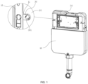
Fig. 1 is a schematic structural diagram of a hidden water tank of embodiment I in a first positioning state; -
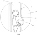
Fig. 2 is a partial schematic structural diagram of the hidden water tank of embodiment I in a second positioning state; -
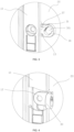
Fig. 3 is a partial schematic structural diagram of a hidden water tank of embodiment II in a first positioning state; -
Fig. 4 is a partial schematic structural diagram of the hidden water tank of embodiment II in a second positioning state; -
Fig. 5 is a partial schematic structural diagram of a hidden water tank of embodiment III in a first positioning state; and -
Fig. 6 is a partial schematic structural diagram of the hidden water tank of embodiment III in a second positioning state. - The present invention provides drawings to further illustrate the various embodiments. The drawings, which are part of the disclosure of the present invention, are mainly used to illustrate the embodiments and can explain the operation principle of the embodiments together with the relevant explanation in the description. With reference to these contents, a person of ordinary skill in the art should be able to understand the advantages of the present invention. Assemblies in the drawings are not drawn to scale, and like reference numerals are usually used to indicate like assemblies.
- The present invention will now be further described with reference to the drawings and particular embodiments.
- In the following embodiments, the term "outward" or "inward" is defined relative to the position of a mounting window, "outward" refers to a direction in which a water tank body faces the mounting window, and "inward" refers to a direction in which the mounting window faces the water tank body. The term "forward" refers to a direction in which an inner side wall of the water tank body faces an outer wall surface of the water tank body, and the term "backward" refers to a direction in which the outer wall surface of the water tank body faces the inner side wall of the water tank body. The terms "upward" and "downward" refer to a vertical direction of the water tank in an assembled state.
- Referring to
Figs. 1 and2 , this embodiment provides a hidden water tank that improves disassembly and assembly of internal assemblies, the hidden water tank comprising awater tank body 10 and amounting seat 30 for a connecting panel (not shown), wherein thewater tank body 10 is provided with amounting window 20, and a plane where themounting window 20 is located is defined as a first plane. Specifically, when the water tank is assembled, themounting window 20 is a vertical window, that is, the first plane is a vertical plane. Themounting seat 30 is movably arranged on thewater tank body 10, specifically, themounting seat 30 is hinged on thewater tank body 10, and more specifically, an axial direction of a hinge shaft (not shown) connecting themounting seat 30 and thewater tank body 10 is perpendicular to the first plane. Themounting seat 30 swings on a parallel plane (also being a vertical plane) parallel to the first plane and can be switched between a first positioning state (as shown inFig. 1 ) in which the mounting seat protrudes in a direction toward the center of themounting window 20 and a second positioning state (as shown inFig. 2 ) in which the mounting seat retracts toward an edge of the mounting window. - When it is necessary to assemble or disassemble an assembly such as a water inlet valve into or from the
water tank body 10, in the state ofFig. 1 , themounting seat 30 is toggled, so that themounting seat 30 swings downward to the second positioning state in which the mounting seat retracts to the edge of the mounting window, as shown inFig. 2 , thus the effective area of themounting window 20 for the access of the assembly can be increased. In this specific embodiment, themounting seat 30 can swing to be completely hidden in thewater tank body 10, which does not affect the access of the assembly at all. After the operation is completed, themounting seat 30 is toggled to swing upward, and themounting seat 30 is switched to the first positioning state in which the mounting seat protrudes in a direction toward the center of themounting window 20, thus realizing a normal fixed assembly with the connecting panel. Without changing the size of original components (such as the size of themounting window 20, the connecting panel, etc.), the problem that it is difficult to disassemble and assemble the internal assemblies in a small-sized water tank structure in the prior art can be effectively solved, and the structure is simple and easy to implement. - Further preferably, in this embodiment, the
mounting seat 30 is arranged on an inner wall surface of thewater tank body 10, thus it can give way to the mounting of the connecting panel, so that the connecting panel can be better attached to an outer wall surface of thewater tank body 10, and the assembly is more stable and simpler. Of course, in other embodiments, themounting seat 30 can also be arranged on the outer wall surface of thewater tank body 10, etc. When themounting seat 30 is arranged on the outer wall surface of thewater tank body 10, themounting seat 30 itself protrudes from the outer wall surface of thewater tank body 10. In order to allow the connecting panel to be attached to the outer wall surface of thewater tank body 10, a clearance groove can be arranged at a position of the connecting panel corresponding to themounting seat 30. When covered, themounting seat 30 is accommodated in the clearance groove, and other positions of the connecting panel can be well attached to the outer wall surface of thewater tank body 10. - Further preferably, in this embodiment, the inner wall surface of the
water tank body 10 is further provided with astop portion 11 in a protruding manner. When themounting seat 30 swings to be perpendicular to an outer edge of themounting window 20, it indicates that the mounting seat moves to a position for the connecting panel, and at this time, the mounting seat is stopped and limited by thestop portion 11 to realize positioning. That is, in this specific embodiment, themounting seat 30 swings in a lower semicircle (i.e., a lower half of a circle), and thestop portion 11 is located above themounting seat 30. When themounting seat 30 swings upward to a position for assembly, the mounting seat is stopped by thestop portion 11, which limits the mounting seat from continuing to swing upward, so that themounting seat 30 can be quickly positioned and the operation is simpler. Of course, in other embodiments, if themounting seat 30 swings in an upper semicircle (i.e., an upper half of a circle), thestop portion 11 is located below themounting seat 30 correspondingly. When themounting seat 30 swings downward to a position for assembly, the mounting seat is stopped by thestop portion 11, which limits the mounting seat from continuing to swing downward. Alternatively, there is no need for the limit of thestop portion 11, and so on. - Further, the movable arrangement of the
mounting seat 30 enables themounting seat 30 to realize a fine adjustment in its movable direction, so as to be better aligned with a mounting structure of the connecting panel. - Further preferably, in this embodiment, the
mounting seat 30 is provided with amounting hole 301, specifically a screw hole, and the mounting seat is fixedly assembled to the connecting panel by means of themounting hole 301. Specifically, the connecting panel is also provided with a mounting hole, and then a bolt is used to pass through the mounting hole in the connecting panel and the mountinghole 301 of the mountingseat 30 in sequence for screw connection and fixation. Of course, in other embodiments, the mounting structure on the mountingseat 30 can also be replaced by other structures, such as clamping grooves, hook and loop fasteners, etc., as long as it can be mounted to and match the structure on the connecting panel. - This embodiment provides a hidden water tank that improves disassembly and assembly of internal assemblies, the structure of which is substantially the same as the structure of embodiment I except in that referring to
Figs. 3 and 4 , in this embodiment, an axial direction of ahinge shaft 13 connecting the mountingseat 30 and thewater tank body 10 is parallel to the first plane, and the mountingseat 30 swings (i.e., swings back and forth) on a perpendicular plane perpendicular to the first plane to be switched between a first positioning state (as shown inFig. 3 ) and a second positioning state (as shown inFig. 4 ). - As in this specific embodiment, when it is necessary to assemble or disassemble an assembly such as a water inlet valve into or from the
water tank body 10, in the first positioning state shown inFig. 3 , the mountingseat 30 is toggled forward, so that the mountingseat 30 swings forward to be switched to the second positioning state in which the mounting seat retracts to the edge of the mounting window, as shown inFig. 4 , thus the effective area of the mountingwindow 30 for the access of the assembly can be increased and the operation is convenient. After the disassembly and assembly operations of the internal assemblies are completed, in the second positioning state shown inFig. 4 , the mountingseat 30 is toggled backward, so that the mountingseat 30 swings backward to the first positioning state in which the mounting seat protrudes in a direction toward the center of the mounting window, as shown inFig. 3 , thus realizing a normal fixed assembly of the connecting panel and the mountingseat 30. - More further preferably, in this embodiment, a fixed
seat 12 is fixedly connected to the inner wall surface of thewater tank body 10, and the mountingseat 30 is hinged to the fixedseat 12, that is, thewater tank body 10 is hinged to the mountingseat 30 by means of the fixedseat 12 arranged on the water tank body. With such an arrangement, when the mountingseat 30 is in the first positioning state, as shown inFig. 3 , the mounting seat does not interfere with the mounting of the connecting panel, so that the connecting panel can be well attached to the outer wall surface of thewater tank body 10. - More specifically, a U-shaped opening (not indicated) with an outward opening is formed at an outer end of the fixed
seat 12, ahinge projection 31 of the mountingseat 30 extends into the U-shaped opening, and a hinged assembly of the U-shaped opening and thehinge projection 31 is realized by means of thehinge shaft 13. That is, thehinge shaft 13 passes through thehinge projection 31, and two ends of the hinge shaft are fixed on two side walls of the U-shaped opening, so as to realize the hinged assembly of the mountingseat 30 and the fixedseat 12. Meanwhile, thehinge projection 31 of the mountingseat 30 also extends inward to a position where the hinge projection can overlap with the inner wall surface of thewater tank body 10. When the mountingseat 30 is toggled backward from the second positioning state shown inFig. 4 to the first positioning state shown inFig. 3 , thehinge projection 31 of the mountingseat 30 can abut against the inner wall surface of thewater tank body 10, thereby limiting the mountingseat 30 from continuing to turn backward, and realizing rapid positioning. Of course, in other embodiments, the configuration of the structure and position of the mountingseat 30 may not be limited to this. For example, the mountingseat 30 may also be directly hinged on a side wall of thewater tank body 10 surrounding the mountingwindow 20 or hinged on the outer wall surface of thewater tank body 10. - This embodiment provides a hidden water tank that improves disassembly and assembly of internal assemblies, the structure of which is substantially the same as the structure of embodiment I except in that referring to
Figs. 5 and 6 , in this embodiment, the mountingseat 30 is slidably arranged on thewater tank body 10, so that the mountingseat 30 can slide and protrude in a direction toward the center of the mountingwindow 20 by sliding relative to thewater tank body 10 to reach a first positioning state (as shown inFig. 5 ); and the mounting seat can slide and retract to the edge of the mountingwindow 20 to reach a second positioning state (as shown inFig. 6 ). Switching between the first positioning state and the second positioning state is realized. - When it is necessary to assemble or disassemble an assembly such as a water inlet valve into or from the
water tank body 10, in the first positioning state shown inFig. 5 , the mountingseat 30 is pressed, so that the mountingseat 30 slides and retracts to the edge of the mountingwindow 20 to reach the second positioning state shown inFig. 6 , thus the effective area of the mountingwindow 20 for the access of the assembly can be increased and the operation is convenient. After the disassembly and assembly operations of the internal assemblies are completed, the mountingseat 30 can be pulled out in a direction toward the center of the mountingwindow 20, which is simple to operate. - Further preferably, in this embodiment, the sliding direction of the mounting
seat 30 is arranged perpendicular to the side wall of the mountingwindow 20. Of course, in other embodiments, it can also be tilted at a certain angle, as long as the switching between the first positioning state and the second positioning state can be ensured. - Further preferably, the inner wall surface of the
water tank body 10 is provided with a slide groove (not shown), and the mountingseat 30 is slidably fitted to the slide groove in the inner wall surface of thewater tank body 10, thereby realizing a slidable assembly. Moreover, the mountingseat 30 is arranged on the inner wall surface of thewater tank body 10, which can give way to the mounting of the connecting panel, so that the connecting panel can be well attached to the outer wall surface of thewater tank body 10. Of course, in other embodiments, the slidable assembly structure and arrangement position of the mountingseat 30 are not limited to this. - Further, the movable arrangement of the mounting
seat 30 enables the mountingseat 30 to realize a fine adjustment in its movable direction, so as to be better aligned with a mounting structure of the connecting panel. - Specifically, two mounting
seats 30 are provided on thewater tank body 10, that is, the mounting seats are respectively arranged on outer edges of two opposite sides of the mountingwindow 20, such as left and right outer edges inFig. 1 , so as to realize the fixed assembly with the connecting panel. Of course, in other embodiments, the number of the mountingseats 30 is not limited to this, and more mounting seats, such as four mounting seats can be provided, that is, the mountingseats 30 are provided on upper, lower, left and right outer edges of the mountingwindow 20. One mounting seat can also be provided. When one mounting seat is provided, thewater tank body 10 can be provided with a structure different from the mountingseat 30, such as a slot. One end of the connecting panel is connected by an insertion fit with the slot, and the other end is mounted by a connection to the mountingseat 30.
Claims (7)
- A hidden water tank for improving disassembly and assembly of internal assemblies, the hidden water tank comprising a water tank body (10) provided with a mounting window (20), and at least one mounting seat (30) positioned at an edge of the mounting window (20) and used for assembling a connecting panel, whereinthe mounting seat (30) is movably connected and arranged on the water tank body (10), and by means of this arrangement of movable connectionof the mounting seat (30), the mounting seat (30) can be switched between a first positioning state in which the mounting seat (30) protrudes in a direction toward the center of the mounting window (20) and a second positioning state in which the mounting seat (30) retracts toward the edge of the mounting window (20),characterised in thatthe arrangement of movable connection of the mounting seat (30) is a hinged arrangement or a slidable arrangement.
- The hidden water tank for improving disassembly and assembly of internal assemblies according to claim 1, wherein the arrangement of movable connection of the mounting seat (30) is the hinged arrangement, characterized in that a plane where the mounting window (20) is located is defined as a first plane, whereby the hinged arrangement comprises a hinge shaft, wherein the axial direction of the hinge shaft connecting the mounting seat and the water tank body (10) is perpendicular to the first plane, and the mounting seat (30) swings on a parallel plane parallel to the first plane and can be switched between the first positioning state and the second positioning state.
- The hidden water tank for improving disassembly and assembly of internal assemblies according to claim 2, characterized in that the mounting seat (30) is arranged on an inner wall surface of the water tank body (10).
- The hidden water tank for improving disassembly and assembly of internal assemblies according to claim 3, characterized in that the inner wall surface of the water tank body (10) is further provided with a stop portion (11) in a protruding manner.
- The hidden water tank for improving disassembly and assembly of internal assemblies according to claim 1, wherein the arrangement of movable connection of the mounting seat (30) is the hinged arrangement, characterized in that a plane where the mounting window (20) is located is defined as a first plane, wherein the hinged arrangement comprises a hinge shaft, and the axial direction of the hinge shaft connecting the mounting seat (30) and the water tank body (10) is parallel to the first plane, and the mounting seat (30) swings on a perpendicular plane perpendicular to the first plane and can be switched between the first positioning state and the second positioning state.
- The hidden water tank that improves disassembly and assembly of internal assemblies according to claim 5, characterized in that a fixed seat is fixedly connected to an inner wall surface of the water tank body (10), and the mounting seat (30) is hinged to the fixed seat.
- The hidden water tank for improving disassembly and assembly of internal assemblies according to claim 1, wherein the arrangement of movable connection of the mounting seat (30) is the slidable arrangement, characterized in that an inner wall surface of the water tank body (10) is provided with a slide groove, and the mounting seat (30) is slidably fitted to the slide groove in the inner wall surface of the water tank body (10).
Applications Claiming Priority (2)
| Application Number | Priority Date | Filing Date | Title |
|---|---|---|---|
| CN202011121425.XA CN112112230A (en) | 2020-10-20 | 2020-10-20 | Hidden water tank capable of improving disassembly and assembly of internal components |
| PCT/CN2021/074982 WO2022083030A1 (en) | 2020-10-20 | 2021-02-03 | Hidden water tank that improves disassembly and assembly of internal assemblies |
Publications (3)
| Publication Number | Publication Date |
|---|---|
| EP4230815A1 EP4230815A1 (en) | 2023-08-23 |
| EP4230815A4 EP4230815A4 (en) | 2024-04-17 |
| EP4230815B1 true EP4230815B1 (en) | 2025-07-02 |
Family
ID=73794594
Family Applications (1)
| Application Number | Title | Priority Date | Filing Date |
|---|---|---|---|
| EP21881456.4A Active EP4230815B1 (en) | 2020-10-20 | 2021-02-03 | Hidden water tank that improves disassembly and assembly of internal assemblies |
Country Status (3)
| Country | Link |
|---|---|
| EP (1) | EP4230815B1 (en) |
| CN (1) | CN112112230A (en) |
| WO (1) | WO2022083030A1 (en) |
Families Citing this family (2)
| Publication number | Priority date | Publication date | Assignee | Title |
|---|---|---|---|---|
| CN112112230A (en) * | 2020-10-20 | 2020-12-22 | 厦门融技精密科技有限公司 | Hidden water tank capable of improving disassembly and assembly of internal components |
| WO2022260624A1 (en) * | 2021-06-09 | 2022-12-15 | Eczacibasi Yapi Gerecleri Sanayi Ve Ticaret Anonim Sirketi | Concealed flush tank system |
Family Cites Families (16)
| Publication number | Priority date | Publication date | Assignee | Title |
|---|---|---|---|---|
| DE1709501A1 (en) * | 1967-12-23 | 1975-11-27 | Gebert & Cie | FLUSH-MOUNTED CLEANER |
| DE4210682C2 (en) * | 1992-04-01 | 1997-12-18 | Schwab Sanitaer Plastic Gmbh | Quick fastening device |
| DE29822703U1 (en) * | 1998-01-28 | 1999-04-15 | PROSAN d.o.o., Ruše | Device for attaching an actuator to a concealed cistern |
| DE102008026843B4 (en) * | 2008-06-05 | 2014-11-06 | Sanitärtechnik Eisenberg GmbH | Actuating device for a sanitary object |
| DE202008010196U1 (en) * | 2008-07-30 | 2009-12-17 | Viega Gmbh & Co. Kg | Drain valve for a cistern |
| EP2336435B1 (en) * | 2009-12-09 | 2015-07-22 | Geberit International AG | Cistern with an odour extractor |
| CN202850152U (en) * | 2012-07-27 | 2013-04-03 | 广东联塑科技实业有限公司 | Hidden type water tank button panel |
| CN204849969U (en) * | 2015-06-18 | 2015-12-09 | 李小满 | Hide water tank panel slidable mounting subassembly |
| CN205369437U (en) * | 2016-01-21 | 2016-07-06 | 中山市保洁士卫浴有限公司 | Improve knead dough hidden flushing cistern of leg joint of fixed square frame |
| CN105544671B (en) * | 2016-01-21 | 2017-12-05 | 中山市保洁士卫浴有限公司 | A kind of attachment means of the side frame edge of concealed toilet cistern and front baffle |
| CN205329801U (en) * | 2016-01-29 | 2016-06-22 | 厦门瑞尔特卫浴科技股份有限公司 | Water tank control panel assembly's mounting structure |
| DE102016011937A1 (en) * | 2016-10-06 | 2018-04-12 | GROHEDAL Sanitärsysteme GmbH | Flush-mounted cistern with inspection shaft and holding frame with a form-fit fastening device for tool-free attachment |
| CN209221615U (en) * | 2018-10-25 | 2019-08-09 | 厦门瑞尔特卫浴科技股份有限公司 | A kind of concealed water tank with screen modules |
| CN211312730U (en) * | 2019-10-15 | 2020-08-21 | 厦门倍洁特建材有限公司 | Hidden water tank of adaptation intelligent closestool |
| CN213682369U (en) * | 2020-10-20 | 2021-07-13 | 厦门融技精密科技有限公司 | A hidden water tank that improves disassembly and assembly of internal components |
| CN112112230A (en) * | 2020-10-20 | 2020-12-22 | 厦门融技精密科技有限公司 | Hidden water tank capable of improving disassembly and assembly of internal components |
-
2020
- 2020-10-20 CN CN202011121425.XA patent/CN112112230A/en active Pending
-
2021
- 2021-02-03 WO PCT/CN2021/074982 patent/WO2022083030A1/en not_active Ceased
- 2021-02-03 EP EP21881456.4A patent/EP4230815B1/en active Active
Also Published As
| Publication number | Publication date |
|---|---|
| EP4230815A1 (en) | 2023-08-23 |
| CN112112230A (en) | 2020-12-22 |
| WO2022083030A1 (en) | 2022-04-28 |
| EP4230815A4 (en) | 2024-04-17 |
Similar Documents
| Publication | Publication Date | Title |
|---|---|---|
| WO2019134633A1 (en) | Drawer type circuit breaker | |
| EP4230815A1 (en) | Hidden water tank that improves disassembly and assembly of internal assemblies | |
| CN111328361B (en) | Flap fitting for furniture, side wall of a furniture body and furniture having a side wall | |
| RU2746288C1 (en) | Flap device and air conditioner | |
| WO2017219487A1 (en) | Synchronous drawer sliding rail system with noise reduction and spring-back functions | |
| WO2020253305A1 (en) | Slide rail and equipment cabinet | |
| US20060156513A1 (en) | Snap hinge for supporting closure elements | |
| JP2013534581A (en) | Hinge structure | |
| US20200071963A1 (en) | Door Locking Device for an Electric Household Appliance, in Particular a Dishwasher, and Electric Household Appliance Provided Therewith | |
| CN112049546B (en) | Structure of inverted type sliding window | |
| CN110056293A (en) | A kind of synchronous limit switching mechanism of furniture revolution sliding door | |
| CN108286861A (en) | Refrigerator | |
| WO2026067011A1 (en) | Multi-joint self-closing hinge and refrigerator | |
| CN213682369U (en) | A hidden water tank that improves disassembly and assembly of internal components | |
| CN218941569U (en) | Coupling mechanism, installation component and rack | |
| CN217760462U (en) | Opening and closing mechanism and bin locking device | |
| CN208445164U (en) | A kind of miniature electric power installs case of suspension type | |
| CN211879802U (en) | Interlocking structure and cabinet body | |
| CN2707913Y (en) | Simplified lock | |
| CN223323357U (en) | Pot body assembly and cooking utensil having the same | |
| CN217842904U (en) | Button structure and shower bath | |
| CN220929050U (en) | Hinge for inwardly opened and inwardly inverted window | |
| EP4621153A1 (en) | Connection device for a wall panel | |
| CN222966544U (en) | Double door nuclear power cabinet | |
| CN216907731U (en) | Quick assembly disassembly formula shower room structure |
Legal Events
| Date | Code | Title | Description |
|---|---|---|---|
| STAA | Information on the status of an ep patent application or granted ep patent |
Free format text: STATUS: THE INTERNATIONAL PUBLICATION HAS BEEN MADE |
|
| PUAI | Public reference made under article 153(3) epc to a published international application that has entered the european phase |
Free format text: ORIGINAL CODE: 0009012 |
|
| STAA | Information on the status of an ep patent application or granted ep patent |
Free format text: STATUS: REQUEST FOR EXAMINATION WAS MADE |
|
| 17P | Request for examination filed |
Effective date: 20230519 |
|
| AK | Designated contracting states |
Kind code of ref document: A1 Designated state(s): AL AT BE BG CH CY CZ DE DK EE ES FI FR GB GR HR HU IE IS IT LI LT LU LV MC MK MT NL NO PL PT RO RS SE SI SK SM TR |
|
| DAV | Request for validation of the european patent (deleted) | ||
| DAX | Request for extension of the european patent (deleted) | ||
| STAA | Information on the status of an ep patent application or granted ep patent |
Free format text: STATUS: EXAMINATION IS IN PROGRESS |
|
| A4 | Supplementary search report drawn up and despatched |
Effective date: 20240318 |
|
| RIC1 | Information provided on ipc code assigned before grant |
Ipc: E03D 1/012 20060101ALI20240312BHEP Ipc: E03D 1/00 20060101AFI20240312BHEP |
|
| 17Q | First examination report despatched |
Effective date: 20240402 |
|
| GRAP | Despatch of communication of intention to grant a patent |
Free format text: ORIGINAL CODE: EPIDOSNIGR1 |
|
| STAA | Information on the status of an ep patent application or granted ep patent |
Free format text: STATUS: GRANT OF PATENT IS INTENDED |
|
| INTG | Intention to grant announced |
Effective date: 20250331 |
|
| GRAS | Grant fee paid |
Free format text: ORIGINAL CODE: EPIDOSNIGR3 |
|
| GRAA | (expected) grant |
Free format text: ORIGINAL CODE: 0009210 |
|
| STAA | Information on the status of an ep patent application or granted ep patent |
Free format text: STATUS: THE PATENT HAS BEEN GRANTED |
|
| AK | Designated contracting states |
Kind code of ref document: B1 Designated state(s): AL AT BE BG CH CY CZ DE DK EE ES FI FR GB GR HR HU IE IS IT LI LT LU LV MC MK MT NL NO PL PT RO RS SE SI SK SM TR |
|
| REG | Reference to a national code |
Ref country code: GB Ref legal event code: FG4D |
|
| REG | Reference to a national code |
Ref country code: CH Ref legal event code: EP |
|
| REG | Reference to a national code |
Ref country code: DE Ref legal event code: R096 Ref document number: 602021033570 Country of ref document: DE |
|
| REG | Reference to a national code |
Ref country code: IE Ref legal event code: FG4D |
|
| REG | Reference to a national code |
Ref country code: NL Ref legal event code: MP Effective date: 20250702 |
|
| PG25 | Lapsed in a contracting state [announced via postgrant information from national office to epo] |
Ref country code: PT Free format text: LAPSE BECAUSE OF FAILURE TO SUBMIT A TRANSLATION OF THE DESCRIPTION OR TO PAY THE FEE WITHIN THE PRESCRIBED TIME-LIMIT Effective date: 20251103 |
|
| PG25 | Lapsed in a contracting state [announced via postgrant information from national office to epo] |
Ref country code: NL Free format text: LAPSE BECAUSE OF FAILURE TO SUBMIT A TRANSLATION OF THE DESCRIPTION OR TO PAY THE FEE WITHIN THE PRESCRIBED TIME-LIMIT Effective date: 20250702 |
|
| REG | Reference to a national code |
Ref country code: AT Ref legal event code: MK05 Ref document number: 1809396 Country of ref document: AT Kind code of ref document: T Effective date: 20250702 |
|
| PG25 | Lapsed in a contracting state [announced via postgrant information from national office to epo] |
Ref country code: IS Free format text: LAPSE BECAUSE OF FAILURE TO SUBMIT A TRANSLATION OF THE DESCRIPTION OR TO PAY THE FEE WITHIN THE PRESCRIBED TIME-LIMIT Effective date: 20251102 |
|
| PG25 | Lapsed in a contracting state [announced via postgrant information from national office to epo] |
Ref country code: NO Free format text: LAPSE BECAUSE OF FAILURE TO SUBMIT A TRANSLATION OF THE DESCRIPTION OR TO PAY THE FEE WITHIN THE PRESCRIBED TIME-LIMIT Effective date: 20251002 |
|
| REG | Reference to a national code |
Ref country code: LT Ref legal event code: MG9D |
|
| PG25 | Lapsed in a contracting state [announced via postgrant information from national office to epo] |
Ref country code: AT Free format text: LAPSE BECAUSE OF FAILURE TO SUBMIT A TRANSLATION OF THE DESCRIPTION OR TO PAY THE FEE WITHIN THE PRESCRIBED TIME-LIMIT Effective date: 20250702 |
|
| PG25 | Lapsed in a contracting state [announced via postgrant information from national office to epo] |
Ref country code: FI Free format text: LAPSE BECAUSE OF FAILURE TO SUBMIT A TRANSLATION OF THE DESCRIPTION OR TO PAY THE FEE WITHIN THE PRESCRIBED TIME-LIMIT Effective date: 20250702 |
|
| PG25 | Lapsed in a contracting state [announced via postgrant information from national office to epo] |
Ref country code: HR Free format text: LAPSE BECAUSE OF FAILURE TO SUBMIT A TRANSLATION OF THE DESCRIPTION OR TO PAY THE FEE WITHIN THE PRESCRIBED TIME-LIMIT Effective date: 20250702 |
|
| PG25 | Lapsed in a contracting state [announced via postgrant information from national office to epo] |
Ref country code: GR Free format text: LAPSE BECAUSE OF FAILURE TO SUBMIT A TRANSLATION OF THE DESCRIPTION OR TO PAY THE FEE WITHIN THE PRESCRIBED TIME-LIMIT Effective date: 20251003 |
|
| PG25 | Lapsed in a contracting state [announced via postgrant information from national office to epo] |
Ref country code: CZ Free format text: LAPSE BECAUSE OF FAILURE TO SUBMIT A TRANSLATION OF THE DESCRIPTION OR TO PAY THE FEE WITHIN THE PRESCRIBED TIME-LIMIT Effective date: 20250702 Ref country code: SE Free format text: LAPSE BECAUSE OF FAILURE TO SUBMIT A TRANSLATION OF THE DESCRIPTION OR TO PAY THE FEE WITHIN THE PRESCRIBED TIME-LIMIT Effective date: 20250702 |
|
| PG25 | Lapsed in a contracting state [announced via postgrant information from national office to epo] |
Ref country code: LV Free format text: LAPSE BECAUSE OF FAILURE TO SUBMIT A TRANSLATION OF THE DESCRIPTION OR TO PAY THE FEE WITHIN THE PRESCRIBED TIME-LIMIT Effective date: 20250702 |
|
| PG25 | Lapsed in a contracting state [announced via postgrant information from national office to epo] |
Ref country code: BG Free format text: LAPSE BECAUSE OF FAILURE TO SUBMIT A TRANSLATION OF THE DESCRIPTION OR TO PAY THE FEE WITHIN THE PRESCRIBED TIME-LIMIT Effective date: 20250702 Ref country code: PL Free format text: LAPSE BECAUSE OF FAILURE TO SUBMIT A TRANSLATION OF THE DESCRIPTION OR TO PAY THE FEE WITHIN THE PRESCRIBED TIME-LIMIT Effective date: 20250702 |
|
| PG25 | Lapsed in a contracting state [announced via postgrant information from national office to epo] |
Ref country code: RS Free format text: LAPSE BECAUSE OF FAILURE TO SUBMIT A TRANSLATION OF THE DESCRIPTION OR TO PAY THE FEE WITHIN THE PRESCRIBED TIME-LIMIT Effective date: 20251002 |
|
| PG25 | Lapsed in a contracting state [announced via postgrant information from national office to epo] |
Ref country code: ES Free format text: LAPSE BECAUSE OF FAILURE TO SUBMIT A TRANSLATION OF THE DESCRIPTION OR TO PAY THE FEE WITHIN THE PRESCRIBED TIME-LIMIT Effective date: 20250702 |
|
| PG25 | Lapsed in a contracting state [announced via postgrant information from national office to epo] |
Ref country code: SM Free format text: LAPSE BECAUSE OF FAILURE TO SUBMIT A TRANSLATION OF THE DESCRIPTION OR TO PAY THE FEE WITHIN THE PRESCRIBED TIME-LIMIT Effective date: 20250702 |
|
| PGFP | Annual fee paid to national office [announced via postgrant information from national office to epo] |
Ref country code: GB Payment date: 20260209 Year of fee payment: 6 |
|
| PG25 | Lapsed in a contracting state [announced via postgrant information from national office to epo] |
Ref country code: DK Free format text: LAPSE BECAUSE OF FAILURE TO SUBMIT A TRANSLATION OF THE DESCRIPTION OR TO PAY THE FEE WITHIN THE PRESCRIBED TIME-LIMIT Effective date: 20250702 |
|
| PGFP | Annual fee paid to national office [announced via postgrant information from national office to epo] |
Ref country code: DE Payment date: 20260217 Year of fee payment: 6 |
|
| PG25 | Lapsed in a contracting state [announced via postgrant information from national office to epo] |
Ref country code: IT Free format text: LAPSE BECAUSE OF FAILURE TO SUBMIT A TRANSLATION OF THE DESCRIPTION OR TO PAY THE FEE WITHIN THE PRESCRIBED TIME-LIMIT Effective date: 20250702 |
|
| PG25 | Lapsed in a contracting state [announced via postgrant information from national office to epo] |
Ref country code: SK Free format text: LAPSE BECAUSE OF FAILURE TO SUBMIT A TRANSLATION OF THE DESCRIPTION OR TO PAY THE FEE WITHIN THE PRESCRIBED TIME-LIMIT Effective date: 20250702 Ref country code: EE Free format text: LAPSE BECAUSE OF FAILURE TO SUBMIT A TRANSLATION OF THE DESCRIPTION OR TO PAY THE FEE WITHIN THE PRESCRIBED TIME-LIMIT Effective date: 20250702 |
|
| PLBE | No opposition filed within time limit |
Free format text: ORIGINAL CODE: 0009261 |
|
| STAA | Information on the status of an ep patent application or granted ep patent |
Free format text: STATUS: NO OPPOSITION FILED WITHIN TIME LIMIT |