EP4230489A1 - System and method for controlling a road vehicle - Google Patents
System and method for controlling a road vehicle Download PDFInfo
- Publication number
- EP4230489A1 EP4230489A1 EP23154707.6A EP23154707A EP4230489A1 EP 4230489 A1 EP4230489 A1 EP 4230489A1 EP 23154707 A EP23154707 A EP 23154707A EP 4230489 A1 EP4230489 A1 EP 4230489A1
- Authority
- EP
- European Patent Office
- Prior art keywords
- vehicle
- neutral
- brake
- hold
- controller
- Prior art date
- Legal status (The legal status is an assumption and is not a legal conclusion. Google has not performed a legal analysis and makes no representation as to the accuracy of the status listed.)
- Pending
Links
Images


Classifications
-
- B—PERFORMING OPERATIONS; TRANSPORTING
- B60—VEHICLES IN GENERAL
- B60W—CONJOINT CONTROL OF VEHICLE SUB-UNITS OF DIFFERENT TYPE OR DIFFERENT FUNCTION; CONTROL SYSTEMS SPECIALLY ADAPTED FOR HYBRID VEHICLES; ROAD VEHICLE DRIVE CONTROL SYSTEMS FOR PURPOSES NOT RELATED TO THE CONTROL OF A PARTICULAR SUB-UNIT
- B60W10/00—Conjoint control of vehicle sub-units of different type or different function
- B60W10/18—Conjoint control of vehicle sub-units of different type or different function including control of braking systems
- B60W10/184—Conjoint control of vehicle sub-units of different type or different function including control of braking systems with wheel brakes
-
- B—PERFORMING OPERATIONS; TRANSPORTING
- B60—VEHICLES IN GENERAL
- B60W—CONJOINT CONTROL OF VEHICLE SUB-UNITS OF DIFFERENT TYPE OR DIFFERENT FUNCTION; CONTROL SYSTEMS SPECIALLY ADAPTED FOR HYBRID VEHICLES; ROAD VEHICLE DRIVE CONTROL SYSTEMS FOR PURPOSES NOT RELATED TO THE CONTROL OF A PARTICULAR SUB-UNIT
- B60W10/00—Conjoint control of vehicle sub-units of different type or different function
- B60W10/10—Conjoint control of vehicle sub-units of different type or different function including control of change-speed gearings
- B60W10/11—Stepped gearings
-
- B—PERFORMING OPERATIONS; TRANSPORTING
- B60—VEHICLES IN GENERAL
- B60W—CONJOINT CONTROL OF VEHICLE SUB-UNITS OF DIFFERENT TYPE OR DIFFERENT FUNCTION; CONTROL SYSTEMS SPECIALLY ADAPTED FOR HYBRID VEHICLES; ROAD VEHICLE DRIVE CONTROL SYSTEMS FOR PURPOSES NOT RELATED TO THE CONTROL OF A PARTICULAR SUB-UNIT
- B60W10/00—Conjoint control of vehicle sub-units of different type or different function
- B60W10/18—Conjoint control of vehicle sub-units of different type or different function including control of braking systems
- B60W10/182—Conjoint control of vehicle sub-units of different type or different function including control of braking systems including control of parking brakes
-
- B—PERFORMING OPERATIONS; TRANSPORTING
- B60—VEHICLES IN GENERAL
- B60W—CONJOINT CONTROL OF VEHICLE SUB-UNITS OF DIFFERENT TYPE OR DIFFERENT FUNCTION; CONTROL SYSTEMS SPECIALLY ADAPTED FOR HYBRID VEHICLES; ROAD VEHICLE DRIVE CONTROL SYSTEMS FOR PURPOSES NOT RELATED TO THE CONTROL OF A PARTICULAR SUB-UNIT
- B60W30/00—Purposes of road vehicle drive control systems not related to the control of a particular sub-unit, e.g. of systems using conjoint control of vehicle sub-units, or advanced driver assistance systems for ensuring comfort, stability and safety or drive control systems for propelling or retarding the vehicle
- B60W30/08—Active safety systems predicting or avoiding probable or impending collision or attempting to minimise its consequences
- B60W30/095—Predicting travel path or likelihood of collision
- B60W30/0953—Predicting travel path or likelihood of collision the prediction being responsive to vehicle dynamic parameters
-
- B—PERFORMING OPERATIONS; TRANSPORTING
- B60—VEHICLES IN GENERAL
- B60W—CONJOINT CONTROL OF VEHICLE SUB-UNITS OF DIFFERENT TYPE OR DIFFERENT FUNCTION; CONTROL SYSTEMS SPECIALLY ADAPTED FOR HYBRID VEHICLES; ROAD VEHICLE DRIVE CONTROL SYSTEMS FOR PURPOSES NOT RELATED TO THE CONTROL OF A PARTICULAR SUB-UNIT
- B60W30/00—Purposes of road vehicle drive control systems not related to the control of a particular sub-unit, e.g. of systems using conjoint control of vehicle sub-units, or advanced driver assistance systems for ensuring comfort, stability and safety or drive control systems for propelling or retarding the vehicle
- B60W30/18—Propelling the vehicle
- B60W30/18009—Propelling the vehicle related to particular drive situations
- B60W30/18054—Propelling the vehicle related to particular drive situations at stand still, e.g. engine in idling state
-
- B—PERFORMING OPERATIONS; TRANSPORTING
- B60—VEHICLES IN GENERAL
- B60W—CONJOINT CONTROL OF VEHICLE SUB-UNITS OF DIFFERENT TYPE OR DIFFERENT FUNCTION; CONTROL SYSTEMS SPECIALLY ADAPTED FOR HYBRID VEHICLES; ROAD VEHICLE DRIVE CONTROL SYSTEMS FOR PURPOSES NOT RELATED TO THE CONTROL OF A PARTICULAR SUB-UNIT
- B60W30/00—Purposes of road vehicle drive control systems not related to the control of a particular sub-unit, e.g. of systems using conjoint control of vehicle sub-units, or advanced driver assistance systems for ensuring comfort, stability and safety or drive control systems for propelling or retarding the vehicle
- B60W30/18—Propelling the vehicle
- B60W30/18009—Propelling the vehicle related to particular drive situations
- B60W30/18109—Braking
- B60W30/18118—Hill holding
-
- B—PERFORMING OPERATIONS; TRANSPORTING
- B60—VEHICLES IN GENERAL
- B60T—VEHICLE BRAKE CONTROL SYSTEMS OR PARTS THEREOF; BRAKE CONTROL SYSTEMS OR PARTS THEREOF, IN GENERAL; ARRANGEMENT OF BRAKING ELEMENTS ON VEHICLES IN GENERAL; PORTABLE DEVICES FOR PREVENTING UNWANTED MOVEMENT OF VEHICLES; VEHICLE MODIFICATIONS TO FACILITATE COOLING OF BRAKES
- B60T2201/00—Particular use of vehicle brake systems; Special systems using also the brakes; Special software modules within the brake system controller
- B60T2201/06—Hill holder; Start aid systems on inclined road
-
- B—PERFORMING OPERATIONS; TRANSPORTING
- B60—VEHICLES IN GENERAL
- B60W—CONJOINT CONTROL OF VEHICLE SUB-UNITS OF DIFFERENT TYPE OR DIFFERENT FUNCTION; CONTROL SYSTEMS SPECIALLY ADAPTED FOR HYBRID VEHICLES; ROAD VEHICLE DRIVE CONTROL SYSTEMS FOR PURPOSES NOT RELATED TO THE CONTROL OF A PARTICULAR SUB-UNIT
- B60W2510/00—Input parameters relating to a particular sub-units
- B60W2510/10—Change speed gearings
- B60W2510/1005—Transmission ratio engaged
- B60W2510/101—Transmission neutral state
-
- B—PERFORMING OPERATIONS; TRANSPORTING
- B60—VEHICLES IN GENERAL
- B60W—CONJOINT CONTROL OF VEHICLE SUB-UNITS OF DIFFERENT TYPE OR DIFFERENT FUNCTION; CONTROL SYSTEMS SPECIALLY ADAPTED FOR HYBRID VEHICLES; ROAD VEHICLE DRIVE CONTROL SYSTEMS FOR PURPOSES NOT RELATED TO THE CONTROL OF A PARTICULAR SUB-UNIT
- B60W2520/00—Input parameters relating to overall vehicle dynamics
- B60W2520/04—Vehicle stop
-
- B—PERFORMING OPERATIONS; TRANSPORTING
- B60—VEHICLES IN GENERAL
- B60W—CONJOINT CONTROL OF VEHICLE SUB-UNITS OF DIFFERENT TYPE OR DIFFERENT FUNCTION; CONTROL SYSTEMS SPECIALLY ADAPTED FOR HYBRID VEHICLES; ROAD VEHICLE DRIVE CONTROL SYSTEMS FOR PURPOSES NOT RELATED TO THE CONTROL OF A PARTICULAR SUB-UNIT
- B60W2540/00—Input parameters relating to occupants
- B60W2540/10—Accelerator pedal position
-
- B—PERFORMING OPERATIONS; TRANSPORTING
- B60—VEHICLES IN GENERAL
- B60W—CONJOINT CONTROL OF VEHICLE SUB-UNITS OF DIFFERENT TYPE OR DIFFERENT FUNCTION; CONTROL SYSTEMS SPECIALLY ADAPTED FOR HYBRID VEHICLES; ROAD VEHICLE DRIVE CONTROL SYSTEMS FOR PURPOSES NOT RELATED TO THE CONTROL OF A PARTICULAR SUB-UNIT
- B60W2540/00—Input parameters relating to occupants
- B60W2540/12—Brake pedal position
-
- B—PERFORMING OPERATIONS; TRANSPORTING
- B60—VEHICLES IN GENERAL
- B60W—CONJOINT CONTROL OF VEHICLE SUB-UNITS OF DIFFERENT TYPE OR DIFFERENT FUNCTION; CONTROL SYSTEMS SPECIALLY ADAPTED FOR HYBRID VEHICLES; ROAD VEHICLE DRIVE CONTROL SYSTEMS FOR PURPOSES NOT RELATED TO THE CONTROL OF A PARTICULAR SUB-UNIT
- B60W2554/00—Input parameters relating to objects
- B60W2554/80—Spatial relation or speed relative to objects
- B60W2554/802—Longitudinal distance
-
- B—PERFORMING OPERATIONS; TRANSPORTING
- B60—VEHICLES IN GENERAL
- B60W—CONJOINT CONTROL OF VEHICLE SUB-UNITS OF DIFFERENT TYPE OR DIFFERENT FUNCTION; CONTROL SYSTEMS SPECIALLY ADAPTED FOR HYBRID VEHICLES; ROAD VEHICLE DRIVE CONTROL SYSTEMS FOR PURPOSES NOT RELATED TO THE CONTROL OF A PARTICULAR SUB-UNIT
- B60W2710/00—Output or target parameters relating to a particular sub-units
- B60W2710/06—Combustion engines, Gas turbines
- B60W2710/0644—Engine speed
- B60W2710/065—Idle condition
Definitions
- the present invention relates to systems and methods for controlling a road vehicle.
- Patent Document 1 JP 2017-48877 A discloses a system for controlling a road vehicle. This known system controls the vehicle braking system to keep the vehicle fully stopped even after the vehicle driver lifts his/her foot off the brake pedal while the vehicle is at a complete stop (brake hold) and puts an automatic gearbox into a neutral state while the vehicle is at a complete stop with the gearbox in DRIVE (neutral hold). This system predicts whether the driver steps on the accelerator pedal (gas pedal) to start the vehicle on the basis of the external environment around the vehicle and reinstates the gearbox out of a neutral state.
- DRIVE neutral hold
- the system can prevent startability from worsening while achieving a better fuel efficiency expected with neutral hold.
- JP 2017-48877 contains no description about an action taken to counteract a failure that the vehicle brake system cannot keep the vehicle fully stopped while the vehicle is at a complete stop.
- one approach is to terminate neutral hold and reinstate the gearbox out of a neural state. This approach, however, hampers the achievement of the improved fuel efficiency expected with neutral hold.
- Another approach is to keep neutral control continuing. This approach, however, causes a risk that the vehicle may roll forward.
- the known system cancels brake hold and neutral hold if the vehicle driver steps on the accelerator pedal inadvertently. This hampers the achievement of the improved fuel efficiency expected. Moreover, there is a risk that the vehicle may roll forward.
- One aspect of the invention provides a system for controlling a road vehicle, including: an automatic gearbox; a parking brake; a vehicle braking system, and a controller configured to control the vehicle braking system in accordance with a brake hold control logic to keep the vehicle fully stopped even after the vehicle driver lifts his/her foot off a brake pedal while the vehicle is at a complete stop in DRIVE, and put the gearbox into neutral in accordance with a neutral hold control logic while the vehicle is at a complete stop in DRIVE, the controller being configured to activate the parking brake, in order for neutral hold to continue, following determination that the vehicle braking system cannot work properly in accordance with the brake hold control logic, thus failing to keep the vehicle fully stopped while the vehicle is at a complete stop in DRIVE.
- the controller is configured to allow neutral hold to continue despite an accidental driver input via the accelerator pedal following determination that at least one of the target objects detected by means of at least one obstacle sensor is too close to and an obstacle to the vehicle while the vehicle is at a complete stop in DRIVE.
- the controller is configured to signal the driver to fix the vehicle braking system following determination that the vehicle braking system cannot work properly in accordance with the brake hold control logic, thus failing to keep the vehicle fully stopped while the vehicle is at a complete stop in DRIVE.
- Another aspect of the invention provides a method of controlling a road vehicle having a vehicle braking system, a parking brake, and an automatic gearbox, the method including: controlling the vehicle braking system in accordance with a brake hold control logic to keep the vehicle fully stopped while the vehicle is at a complete stop in DRIVE; putting the gearbox into neutral in accordance with a neutral hold control logic while the vehicle is at a complete stop in DRIVE, and activating the parking brake, in order for neutral hold to continue, following determination that the vehicle braking system cannot work properly in accordance with the neutral hold control logic, thus failing keep the vehicle fully stopped while the vehicle is at a complete stop in DRIVE.
- the method includes detecting one or more target objects in an environment ahead of and in the path of the vehicle, and allowing neutral hold to continue despite an accidental driver input via the accelerator pedal following determination that at least one of the target objects detected is too close to and an obstacle to the vehicle while the vehicle is at a complete stop in DRIVE.
- a system for controlling a road vehicle includes: an automatic gearbox; a parking brake; a vehicle braking system, and a controller configured to control the vehicle braking system in accordance with a brake hold control logic to keep the vehicle fully stopped even after the vehicle driver lifts his/her foot off a brake pedal while the vehicle is at a complete stop in DRIVE, and put the gearbox into neutral in accordance with a neutral hold control logic while the vehicle is at a complete stop in DRIVE.
- the controller is configured to activate the parking brake, in order for neutral hold to continue, following determination that the vehicle braking system cannot work properly in accordance with the brake hold control logic, thus failing to keep the vehicle fully stopped while the vehicle is at a complete stop in DRIVE. This system improves fuel efficiency and safety.
- FIG. 1 shows a system for controlling a vehicle 1 in accordance with the present invention.
- the vehicle 1 includes an engine 2, an automatic gearbox 3, a vehicle braking system 4, a parking brake 5, and a controller 10.
- the engine 2 has two or more cylinders.
- the engine 2 is a four-stroke internal combustion engine in which the piston in each cylinder completes four separate strokes (i.e., intake, compression, combustion, and exhaust) while turning the crankshaft.
- the automatic gearbox 3 has a power input shaft, not shown, connected to an external motive power source, typically the crankshaft of the internal combustion engine 2, changes gears (or speed ratios) between the power input shaft and a power output shaft, not shown.
- the automatic gearbox 3 has a ratio changing mechanism to adjust a speed ratio between the rotation of the power input shaft and the rotation of the power output shaft in a stepwise manner or a stepless manner.
- the ratio changing mechanism includes but not limited to a planetary geartrain, not shown, or a V-belt which runs between two variable-diameter pulleys, not shown.
- the automatic gearbox 3 has a forward clutch mechanism, not shown, located on the power input shaft.
- the forward clutch mechanism may be hydraulically operated and disengages to put the automatic gearbox 3 into a neutral state in which power transfer between the power input shaft and power output shaft is interrupted.
- a torque converter connects the engine 2 to the power input shaft of the automatic gearbox 3. With the forward clutch mechanism being disengaged, the automatic gearbox 3 is in a neutral state to apply no substantial load to the turbine of the torque converter, allowing the engine 2 to idle with good fuel efficiency.
- the vehicle braking system 4 transmits the pedal force to brakes by means of a confined hydraulic fluid through force transmission.
- the force applying to the brake pedal 22A is multiplied and transmitted to all the brakes.
- the vehicle braking system 4 includes a master cylinder.
- the master cylinder is connected by tubing to the wheel cylinder on each of the wheels.
- the hydraulic pressure in the braking system 4 is increased or held in response to a control signal from a controller 10, which will be described later. This is achieved by means of a hydraulic circuit and valves in the braking system 4.
- the parking brake 5 is engaged to ensure that a parked vehicle stays in place, especially on hills and other declines. When engaged, it locks the wheels in place and ensures that the vehicle does not roll away.
- the parking brake 5 is an electric parking brake that is actuated by an electric motor, not shown, and automatically engaged in response to a control signal from the controller 10 aside from the driver input.
- the controller 10 is a computer unit that includes a central processing unit (CPU), a random access memory (RAM), a read only memory (ROM), a flash memory for storing backup data, input ports, and output ports.
- CPU central processing unit
- RAM random access memory
- ROM read only memory
- flash memory for storing backup data, input ports, and output ports.
- the ROM of this computer unit stores a program or programs, on which the computer unit runs to achieve features the controller 10 is expected to have, together with various constants, maps and the like.
- the CPU executes the programs stored in the ROM using the RAM as a work area, and so the computer unit achieves features the controller 10 is expected to have.
- Various sensors including an accelerator pedal sensor 21, a brake pedal sensor 22, a selector position sensor 23, a vehicle speed sensor 24, and at least one obstacle sensor 25 are connected to the input ports of the controller 10 .
- the accelerator pedal sensor 21 detects the driver input via the accelerator pedal 21A and provides, as an input, a signal indicative of the result of detection to the controller 10 .
- the brake pedal sensor 22 detects the driver input via the brake pedal 22A and provides, as an input, a signal indicative of the result of detection to the controller 10.
- the selector position sensor 23 detects the selected position of the selector 23A manipulated by the driver and provides, as an input, a signal indicative of the selected position to the controller 10.
- the positions which may be selected by the selector 23A include park “PARK,” reverse “REVERSE, " neutral “NEUTRAL,” and drive “DRIVE. "
- the vehicle speed sensor 24 detects the speed of vehicle 1 and provides, as an input, a signal indicative of the detected vehicle speed to the controller 10.
- the at least one obstacle sensor 25 detects one or more target objects in an environment ahead of and in the path of the vehicle 1, and it provides, as an input, signals indicative of the detected one or more target objects to the controller 10.
- the obstacle sensor 25 has a camera and/or a radar, not shown, which are arranged for detecting, as target objects, other vehicles, pedestrians, and the like.
- controller 10 Connected to the output ports of the controller 10 are various targets subject to control which include the engine 2, automatic gearbox 3, vehicle braking system 4, and parking brake 5.
- the controller 10 includes a neutral hold control logic, a brake hold control logic, a cruise control logic, and an autobrake control logic.
- the vehicle 1 has a brake hold feature, a cruise control feature, and an autobrake feature.
- Brake Hold automatically holds the brakes for the driver while at a complete stop.
- the driver can lift his/her foot off the brake pedal 22A once fully stopped, and "Brake Hold” will keep the vehicle 1 fully stopped.
- the control unit 10 increases or maintains the hydraulic pressure within the wheel cylinders of the braking system 4 to keep the vehicle 1 fully stopped even after the driver lifts his/her foot off the brake pedal 22A.
- the driver can lift his/her foot off the brake pedal 22A when the vehicle comes to a complete stop without interrupting braking force to keep the vehicle 1 fully stopped until the driver presses the accelerator pedal 21A.
- Cruise control is a system that automatically controls the speed of the vehicle 1 by accelerating or slowing the vehicle 1 to maintain a steady speed set by the driver, and so the driver can lift his/her off the accelerator pedal 21A. If approaching a vehicle ahead having a speed lower than the speed set by the driver, the cruise control system adjusts the speed of the vehicle 1 to maintain a safe distance from the vehicle ahead. Using the information from the obstacle sensor 25, the controller 10 adjusts engine torque of the engine 2, gear in the automatic gearbox 3 and brake pressure, i.e., brake force, in the wheel cylinders of the braking system 4 to accelerate or decelerate or stop the vehicle 1 to maintain a safe distance from the vehicle ahead.
- brake pressure i.e., brake force
- the cruise control system in this example may be called adaptive cruise control (ACC) or cruise control with a follow-up feature.
- ACC adaptive cruise control
- cruise control with a follow-up feature This cruise control system is useful for long drives across highways and can reduce driver fatigue and improve comfort by allowing positioning changes more safely.
- Automatic braking is a part of cruise control, and it is a system that automatically controls hydraulic pressure in the braking system 4 to slow or stop the vehicle 1 even if the drive lifts his/her foot off brake pedal 22A.
- the controller 10 executes automatic braking while performing cruise control.
- Neutral Hold is a system that puts the automatic gearbox 3 in neutral while the vehicle 1 is at a complete stop with the automatic gearbox in DRIVE.
- the controller 10 puts the automatic gearbox 3 into neutral following determination that the selector 23A is in DRIVE, the vehicle 1 is at a complete stop, the brake pedal 22A is pressed, and the accelerator pedal 21A is not pressed.
- One advantage of neutral hold is good fuel efficiency to maintain a steady idling speed of the engine 2 while the vehicle 1 is at a complete stop because the torque converter coupled to the automatic gearbox 3 does not apply load to the engine 2.
- Brain Hold may fail to work properly during "Neutral Hold.”
- the vehicle braking system 4 does not work properly, in accordance with the brake hold logic, and fails to keep the vehicle 1 fully stopped.
- the cause of such a failure of "Brake Hold” is inadequate operation of a hydraulic pressure hold solenoid. Even in such a case, the vehicle braking system 4 will keep the vehicle 1 fully stopped if the driver steps on the brake pedal 22A. Deactivating "Neutral Hold” is one approach, but this approach proves to be inappropriate in achieving a better fuel economy expected with "Neutral Hold” and requires the driver to step on the brake pedal 22A to keep the vehicle 1 fully stopped.
- the controller 10 is configured to put the parking brake 5 on, in order for "Neutral Hold” to continue, following determination that the vehicle braking system 4 cannot work properly in accordance with a neutral hold control logic, thus failing to keep the vehicle 1 fully stopped.
- the controller 10 is configured to disable a torque command in response to a rapid increase in driver input via the accelerator pedal 21A, in order for neutral hold to continue, following determination that at least one of the target objects detected in a circumstance ahead of and in the path of the vehicle 1 by means of the at least one obstacle sensor 25 is too close to and an obstacle to the vehicle 1.
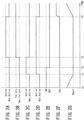
- FIG. 2A through FIG. 2G illustrate how "Brake Hold” and “Neutral Hold” operate while the vehicle 1 is at a complete stop in DRIVE if a failure of "Brake Hold” happens during "Neutral Hold.”
- FIG. 2A through FIG, 2G illustrate actions taken by the controller 10 if the vehicle braking system 4 does not work properly, in accordance with the brake hold control logic, and fails to keep the vehicle 1 fully stopped (a failure of "Brake Hold") during "Neutral Hold” while the vehicle is at a complete stop in DRIVE (or with the selector 23A being in DRIVE).
- FIG. 2A through FIG. 2G are example plots of the status of the parking brake 5, the failure status of the hydraulic pressure control, the status of "Brake Hold”, the status of "Neutral Hold”, the status of the brake pedal 22A, the status of accelerator (gas) pedal 21A, and vehicle speed, respectively.
- the horizontal axis represents time.
- FIG. 2A the parking brake 5 is activated (labelled “Active") or not activated (labelled “Not Active”).
- FIG. 2B the hydraulic pressure control in the vehicle braking system 4 works properly (labelled “Not Failure") or it does not work properly (labelled “Failure”).
- FIG. 2C “Brake Hold” is not activated (labelled “Not Active”) or activated (labelled “Active”).
- FIG. 2D “Neutral Hold” is not activated (labelled “Not Active”) or activated (labelled “Active”).
- FIG. 2E the status of the brake pedal 22A is ON while the brake pedal 22A is pressed beyond a threshold (labelled “ON”) or otherwise OFF (labelled “OFF”).
- FIG. 2F is an example plot of the accelerator pedal position.
- FIG. 2G is an example plot of the vehicle speed.
- the vehicle 1 comes to a holt in DRIVE (i.e., with its gearbox 3 in DRIVE), and so the vehicle speed is 0 km/h (see FG. 2G).
- the controller 10 activates "Brake Hold” (see “Active” in FIG, 2C ) and "Neutral Hold” (see “Active” in FIG. 2D ).
- the controller 10 controls the vehicle braking system 4 using a brake hold control logic to keep the vehicle 1 fully stopped and puts the gearbox 3 into neutral using a neutral hold control logic following determination that the vehicle 1 is at a complete stop in DRIVE.
- the controller 10 controls the vehicle braking system 4 to keep the vehicle 1 fully stopped, in order for "Neutral Hold” to continue, even after the driver lifts his/her foot off the brake pedal 22A.
- the controller 10 activates the parking brake 5 (see “Active” in FIG. 2A ), in order for "Neutral Hold” to continue, to keep the vehicle 1 fully stopped following determination that the vehicle braking system 4 cannot work properly in accordance with the brake hold control logic, thus failing to keep the vehicle 1 fully stopped.
- the controller 10 may determine whether the parking brake 5 can keep the vehicle 1 fully stopped before allowing "Neutral Hold” to continue.
- the controller 10 deactivates "Brake Hold” (see “Not Active” in FIG. 2C ) as the braking system 4 does not work properly in accordance with the brake hold control logic, thus failing to keep the vehicle 1 fully stopped.
- the controller 10 switches control from the braking system 4 to the parking brake 5 to take over the control of the parking brake 5 to create sufficient brake force for keeping the vehicle 1 fully stopped in order for "Neutral Hold" to continue.
- FIG. 3A through FIG. 3G and FIG. 4A through FIG. 4G it is described how "Neutral Hold" operates in response to a driving in which an obstacle is too close to and an obstacle to the vehicle 1. Such driving occurs during stop-and-go traffic. That is, FIG. 3A through FIG. 3G and FIG. 4A through FIG.
- 4G illustrate actions taken by the controller 10 during stop-and-go traffic in which the driver steps on the brake pedal 22A to approach an object, i.e., a vehicle ahead, so the vehicle 1 slows down in DRIVE to come to a halt with the object being too close to and an obstacle to the vehicle 1, "Brake Hold" is activated following determination that the vehicle 1 is at a complete stop in DRIVE, and then the driver steps on the accelerator pedal 21A to restart the vehicle 1.
- the vertical axis represents the status of approaching objects.
- the vertical axis represents "Brake Hold”.
- the vertical axis represents "Neutral Hold”.
- the vertical axis represents the status of determination whether or not accidental driver operation happens.
- the vertical axis represents the status of the brake pedal 22A.
- the vertical axis represents the accelerator pedal position.
- the vertical axis represents the vehicle speed.
- the horizontal axis represents time.
- the status of approaching objects is ON under the circumstance that at least one of target objects in an environment ahead of and in the path of the vehicle is too close to and an obstacle to the vehicle 1, otherwise it is OFF.
- "Brake Hold” is not activated (labelled “Not Active”) or activated (labelled “Active”).
- “Neutral Hold” is not activated (labelled “Not Active”) or activated (labelled “Active”).
- the status of determination whether or not accidental driver operation happens is ON when the driver inadvertently and rapidly steps on the accelerator pedal 21A under the circumstance that at least one of target objects in an environment ahead of and in the path of the vehicle is too close to and an obstacle to the vehicle 1, otherwise it is OFF.
- the status of the brake pedal 22A is ON when the vehicle driver presses the brake pedal 22 beyond a threshold (labelled "ON"), otherwise it is OFF (labelled "OFF").
- FIG. 3A through FIG. 3G illustrate how "Brake Hold” and "Neutral Hold” operate while the vehicle 1 is at a complete stop in DRIVE if, during "Neutral Hold", the driver inadvertently and rapidly steps on the accelerator pedal 21A under the circumstance that at least one of target objects in an environment ahead of and in the path of the vehicle is too close to and an obstacle to the vehicle 1.
- the driver steps on the brake pedal 22A (see “ON” in FIG. 3E ) with the accelerator pedal 21A released (see “0%” in FIG. 3F ), so the vehicle slows down (see FIG. 3G ).
- the controller 10 determines that at least one of target objects in an environment ahead of and in the path of the vehicle is too close to and an obstacle to the vehicle 1 and turns ON the status of approaching objects (see “ON” in FIG. 3A ).
- the controller 10 deactivates “Brake Hold” (see “Not Active” in FIG. 3B ) and “Neutral Hold” (see “Not Active” in FIG. 3C ).
- the accelerator pedal 21A is released, so the controller 10 turns OFF the status of determination whether or not accidental driver operation happens (see “OFF” in FIG. 3D ), thus determining that no accidental driver operation happens.
- the controller 10 activates "Brake Hold” (see “Active” in FIG, 3B ) and “Neutral Hold” (see “Active” in FIG. 3C ).
- the driver inadvertently and rapidly presses the accelerator pedal 21A (i.e., an accidental drive input via the accelerator pedal 21A) while the status of approaching object(s) is ON (see FIG. 3A ), i.e., under the circumstance that at least one of target objects in an environment ahead of and in the path of the vehicle is too close to and an obstacle to the vehicle 1, so the controller 10 determines that an accidental driver input via the accelerator pedal 21A happens and turns ON the status of determination whether or not accidental driver operation happens (see “ON” in FIG. 3D ). In accordance with the normal settings, the controller 10 deactivates "Brake Hold” (see “Not Active” in FIG.
- the controller 10 determines that the accidental driver input is over when the driver lifts his/her foot off the accelerator pedal 21A, so the controller 10 turns OFF the status of determination whether or not accidental driver operation happens.
- the controller 10 does not determine that at least one of target objects in an environment ahead of and in the path of the vehicle is too close to and an obstacle to the vehicle 1 and turns OFF the status of approaching objects (see "OFF" in FIG. 3A ). Such a status occurs when the vehicle ahead has started and left the vehicle 1.
- the controller 10 deactivates "Brake Hold”, but keeps “Neutral Hold” activated to interrupt power path to the drive wheels following determination that the accidental driver operation to press the accelerator pedal 21A happens, thus preventing the engine power from being delivered to the drive wheels.
- FIG. 4A through FIG. 4G illustrate how "Brake Hold” and “Neutral Hold” operate while the vehicle 1 is at a complete stop in DRIVE if the driver deliberately steps on the accelerator pedal 21A, without any accidental driver operation, under the circumstance that at least one of target objects in an environment ahead of and in the path of the vehicle is too close to and an obstacle to the vehicle 1. Such a driving occurs during stop-and-go traffic.
- the driver steps on the brake pedal 22A (see “ON” in FIG. 4E ) with the accelerator pedal 21A released (see “0%” in FIG. 4F ), so the vehicle slows down (see FIG. 4G ).
- the controller 10 determines that at least one of target objects in an environment ahead of and in the path of the vehicle is too close to and an obstacle to the vehicle 1, and turns ON the status of approaching objects (see FIG. 4A ).
- the controller 10 deactivates "Brake Hold” (see “Not Active” in FIG. 4B ) and “Neutral Hold” (see “Not Active” in FIG. 4C ).
- the accelerator pedal 21A is released, so the controller 10 turns OFF the status of determination whether or not accidental driver operation happens (see “OFF” in FIG. 4D ), thus determining that no accidental driver operation happens.
- the vehicle 1 comes to a holt in DRIVE (i.e., with its gearbox 3 in DRIVE), so the vehicle speed is 0 km/h (see FG. 4G).
- the controller 10 activates "Brake Hold” (see “Active” in FIG, 4B ) and “Neutral Hold” (see “Active” in FIG. 4C ).
- the controller 10 deactivates "Brake Hold". Because the driver does not inadvertently and rapidly press the accelerator pedal 21A at time t23, the controller 10 does not determine that accidental driver operation happens and keeps the status of determination whether or not accidental driver operation happens turned OFF (see “OFF” in FIG. 4D ), and it deactivates "Neutral Hold", too. Because both "Brake Hold” and “Neutral Hold” are deactivated in response to the deliberate driver operation to step on the accelerator pedal 21A, the vehicle 1 starts, and the vehicle speed increases (see FIG. 4G ).
- the controller 10 does not determine that at least one of target objects in an environment ahead of and in the path of the vehicle is too close to and an obstacle to the vehicle 1, and turns OFF the status of approaching objects (see “OFF” in FIG. 4A ).
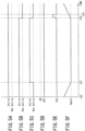
- FIG. 5A through FIG. 5F illustrate how "Neutral Hold” operates if a cruise control system featuring automatic braking keeps the vehicle 1 fully stopped while the vehicle is at a complete stop in DRIVE.
- FIG. 5A through FIG. 5F are example plots of the status of the cruise control, the status of the automatic braking, the status of "Neutral Hold", the status of the brake pedal, the accelerator pedal position, and the vehicle speed, respectively.
- the horizontal axis represents time.
- FIG. 5A the cruise control is activated (labelled “Active") or not activated (labelled “Not Active”).
- the automatic braking is not activated (labelled “Not Active”) or activated (labelled “Active”).
- FIG. 5C “Neutral Hold” is not activated (labelled “Not Active”) or activated (labelled “Active”).
- FIG. 5D the status of the brake pedal 22A is ON while the brake pedal 22A is pressed beyond a threshold (labelled “ON”) or otherwise OFF (labelled “OFF”).
- FIG. 5E is an example plot of the accelerator pedal position.
- FIG. 5F is an example plot of the vehicle speed.
- the cruise control is active (see “Active” in FIG. 5A ), allowing the driver to maintain the same speed without having to keep his/her foot on the accelerator pedal 21A or brake pedal 22A.
- the cruise control activates the automatic braking (see “Active” in FIG. 5B ) to slow the vehicle 1 down to follow another vehicle in front of the vehicle 1. In this situation, "Neutral Hold” is not activated (see “Not Active” in FIG. 5C ).
- the driver is allowed to lift his/her foot off the accelerator pedal 21A because the cruise control accelerates the vehicle 1 to maintain the speed set by the driver or slows the vehicle 1 down to match the speed that another vehicle ahead of the vehicle 1 is travelling to follow the vehicle at a specific distance.
- the controller 10 allows "Neutral Hold” to continue even under this circumstance that the automatic braking system works properly in accordance with a brake hold control logic to keep the vehicle 1 fully stopped while the vehicle 1 is at a complete stop. This prolongs the duration of "Neutral Hold,” thus improving the fuel efficiency.
- controller 10 is configured to activate the parking brake 5, in order for "Neutral Hold” to continue, following determination that the vehicle braking system 4 cannot work properly in accordance with a brake hold control logic, thus failing to keep the vehicle 1 fully stopped while the vehicle 1 is at a complete stop in DRIVE.
- the controller 10 is configured to allow "Neutral Hold” to continue even under the circumstance that the vehicle braking system 4 cannot work properly in accordance with a brake hold control logic, thus failing to keep the vehicle 1 fully stopped. This prolongs the duration of "Neutral Hold,” thus improving the fuel efficiency.
- controller 10 is configured to activate the braking brake 5 to keep the vehicle fully stopped even under the above-mentioned circumstance. This improves safety.
- the controller 10 is configured to signal the driver to fix the vehicle braking system 4 following determination that the vehicle braking system 4 cannot work properly in accordance with the brake hold control logic, thus failing to keep the vehicle 1 fully stopped while the vehicle 1 is at a complete stop in DRIVE.
- controller 10 is configured to allow neutral hold to continue despite an accidental driver input via the accelerator pedal 21A following determination that at least one of the target objects detected by means of at least one obstacle sensor 25 is too close to and an obstacle to the vehicle 1 while the vehicle (1) is at a complete stop in DRIVE.
- controller 10 is configured to reactivate "Brake Hold” following determination that the driver lifts his/her foot off the accelerator pedal 21A and steps on the brake pedal 22A upon recognition that the accidental driver input via the accelerator pedal 21A happened. This keeps the vehicle 1 fully stopped again, so improves safety.
Landscapes
- Engineering & Computer Science (AREA)
- Transportation (AREA)
- Mechanical Engineering (AREA)
- Chemical & Material Sciences (AREA)
- Combustion & Propulsion (AREA)
- Automation & Control Theory (AREA)
- Control Of Driving Devices And Active Controlling Of Vehicle (AREA)
- Regulating Braking Force (AREA)
- Control Of Transmission Device (AREA)
Abstract
A system for controlling a road vehicle is disclosed. The system includes a controller (10). The controller (10) controls the vehicle braking system (4) in accordance with a brake hold control logic to keep the vehicle (1) fully stopped even after the vehicle driver lifts his/her foot off the brake pedal (22A) while the vehicle is at a complete stop in DRIVE, and put the gearbox (3) into neutral in accordance with a neutral hold control logic while the vehicle is at a complete stop in DRIVE. The controller (10) activates the parking brake (5), in order for "Neutral Hold" to continue, following determination that the vehicle braking system (4) cannot work properly in accordance with the brake hold control logic, thus failing to keep the vehicle (1) fully stopped. The controller (10) allows "Neutral Hold" to continue despite an inadvertent and rapid increase in driver input via the accelerator pedal (21A) following determination that at least one of the target objects detected is too close to and an obstacle to the vehicle (1) while the vehicle (1) is at a complete stop.
Description
- The present invention relates to systems and methods for controlling a road vehicle.
-
JP 2017-48877 A - Because it reinstates the gearbox out of a neutral state before the driver starts the vehicle, the system can prevent startability from worsening while achieving a better fuel efficiency expected with neutral hold.
- [Patent Document 1]
JP 2017-48877 A - The system described in
JP 2017-48877 - In addition, the known system cancels brake hold and neutral hold if the vehicle driver steps on the accelerator pedal inadvertently. This hampers the achievement of the improved fuel efficiency expected. Moreover, there is a risk that the vehicle may roll forward.
- Thus, there exists a need for a system and method for controlling a vehicle to improve fuel efficiency and safety while the vehicle is at a complete stop.
- One aspect of the invention provides a system for controlling a road vehicle, including: an automatic gearbox; a parking brake; a vehicle braking system, and a controller configured to control the vehicle braking system in accordance with a brake hold control logic to keep the vehicle fully stopped even after the vehicle driver lifts his/her foot off a brake pedal while the vehicle is at a complete stop in DRIVE, and put the gearbox into neutral in accordance with a neutral hold control logic while the vehicle is at a complete stop in DRIVE, the controller being configured to activate the parking brake, in order for neutral hold to continue, following determination that the vehicle braking system cannot work properly in accordance with the brake hold control logic, thus failing to keep the vehicle fully stopped while the vehicle is at a complete stop in DRIVE.
- In a further aspect of the invention, the controller is configured to allow neutral hold to continue despite an accidental driver input via the accelerator pedal following determination that at least one of the target objects detected by means of at least one obstacle sensor is too close to and an obstacle to the vehicle while the vehicle is at a complete stop in DRIVE.
- Optionally, the controller is configured to signal the driver to fix the vehicle braking system following determination that the vehicle braking system cannot work properly in accordance with the brake hold control logic, thus failing to keep the vehicle fully stopped while the vehicle is at a complete stop in DRIVE.
- Another aspect of the invention provides a method of controlling a road vehicle having a vehicle braking system, a parking brake, and an automatic gearbox, the method including: controlling the vehicle braking system in accordance with a brake hold control logic to keep the vehicle fully stopped while the vehicle is at a complete stop in DRIVE; putting the gearbox into neutral in accordance with a neutral hold control logic while the vehicle is at a complete stop in DRIVE, and activating the parking brake, in order for neutral hold to continue, following determination that the vehicle braking system cannot work properly in accordance with the neutral hold control logic, thus failing keep the vehicle fully stopped while the vehicle is at a complete stop in DRIVE.
- Furthermore, the method includes detecting one or more target objects in an environment ahead of and in the path of the vehicle, and allowing neutral hold to continue despite an accidental driver input via the accelerator pedal following determination that at least one of the target objects detected is too close to and an obstacle to the vehicle while the vehicle is at a complete stop in DRIVE.
- As described, both fuel efficiency and safety are improved.
-
-
FIG. 1 is a block diagram of an example system and method for controlling a vehicle. -
FIG. 2A through FIG. 2G are example plots of the status of the parking brake, the failure status of the hydraulic pressure control, the status of "Brake Hold", the status of "Neutral Hold", the status of the brake pedal, the status of accelerator (gas) pedal, and vehicle speed, respectively. -
FIG. 3A through FIG. 3G are example plots of the status of approaching object(s), the status of "Brake Hold", the status of "Neutral Hold", the status of determination whether or not accidental driver operation happens, the status of the brake pedal, the accelerator pedal position, and the vehicle speed, respectively. -
FIG. 4A through FIG. 4G are example plots of the status of approaching object(s), the status of "Brake Hold", the status of "Neutral Hold", the status of determination whether or not accidental driver operation happens, the status of the brake pedal, the accelerator pedal position, and the vehicle speed, respectively. -
FIG. 5A through 5F are example plots of the status of the cruise control, the status of the automatic braking, the status of "Neutral Hold", the status of the brake pedal, the accelerator pedal position, and the vehicle speed, respectively - A system for controlling a road vehicle is disclosed. The system includes: an automatic gearbox; a parking brake; a vehicle braking system, and a controller configured to control the vehicle braking system in accordance with a brake hold control logic to keep the vehicle fully stopped even after the vehicle driver lifts his/her foot off a brake pedal while the vehicle is at a complete stop in DRIVE, and put the gearbox into neutral in accordance with a neutral hold control logic while the vehicle is at a complete stop in DRIVE. The controller is configured to activate the parking brake, in order for neutral hold to continue, following determination that the vehicle braking system cannot work properly in accordance with the brake hold control logic, thus failing to keep the vehicle fully stopped while the vehicle is at a complete stop in DRIVE. This system improves fuel efficiency and safety.
- Referring to the accompanying drawings,
FIG. 1 shows a system for controlling avehicle 1 in accordance with the present invention. Thevehicle 1 includes anengine 2, anautomatic gearbox 3, avehicle braking system 4, aparking brake 5, and acontroller 10. - The
engine 2 has two or more cylinders. In this example, theengine 2 is a four-stroke internal combustion engine in which the piston in each cylinder completes four separate strokes (i.e., intake, compression, combustion, and exhaust) while turning the crankshaft. - The
automatic gearbox 3 has a power input shaft, not shown, connected to an external motive power source, typically the crankshaft of theinternal combustion engine 2, changes gears (or speed ratios) between the power input shaft and a power output shaft, not shown. Theautomatic gearbox 3 has a ratio changing mechanism to adjust a speed ratio between the rotation of the power input shaft and the rotation of the power output shaft in a stepwise manner or a stepless manner. The ratio changing mechanism includes but not limited to a planetary geartrain, not shown, or a V-belt which runs between two variable-diameter pulleys, not shown. - The
automatic gearbox 3 has a forward clutch mechanism, not shown, located on the power input shaft. The forward clutch mechanism may be hydraulically operated and disengages to put theautomatic gearbox 3 into a neutral state in which power transfer between the power input shaft and power output shaft is interrupted. A torque converter connects theengine 2 to the power input shaft of theautomatic gearbox 3. With the forward clutch mechanism being disengaged, theautomatic gearbox 3 is in a neutral state to apply no substantial load to the turbine of the torque converter, allowing theengine 2 to idle with good fuel efficiency. - To stop or slow down the
vehicle 1, thevehicle braking system 4 transmits the pedal force to brakes by means of a confined hydraulic fluid through force transmission. The force applying to thebrake pedal 22A is multiplied and transmitted to all the brakes. Thevehicle braking system 4 includes a master cylinder. The master cylinder is connected by tubing to the wheel cylinder on each of the wheels. The hydraulic pressure in thebraking system 4 is increased or held in response to a control signal from acontroller 10, which will be described later. This is achieved by means of a hydraulic circuit and valves in thebraking system 4. - The
parking brake 5 is engaged to ensure that a parked vehicle stays in place, especially on hills and other declines. When engaged, it locks the wheels in place and ensures that the vehicle does not roll away. Theparking brake 5 is an electric parking brake that is actuated by an electric motor, not shown, and automatically engaged in response to a control signal from thecontroller 10 aside from the driver input. - The
controller 10 is a computer unit that includes a central processing unit (CPU), a random access memory (RAM), a read only memory (ROM), a flash memory for storing backup data, input ports, and output ports. - The ROM of this computer unit stores a program or programs, on which the computer unit runs to achieve features the
controller 10 is expected to have, together with various constants, maps and the like. - That is, the CPU executes the programs stored in the ROM using the RAM as a work area, and so the computer unit achieves features the
controller 10 is expected to have. - Various sensors including an
accelerator pedal sensor 21, abrake pedal sensor 22, aselector position sensor 23, avehicle speed sensor 24, and at least oneobstacle sensor 25 are connected to the input ports of thecontroller 10 . - The
accelerator pedal sensor 21 detects the driver input via theaccelerator pedal 21A and provides, as an input, a signal indicative of the result of detection to thecontroller 10 . - The
brake pedal sensor 22 detects the driver input via thebrake pedal 22A and provides, as an input, a signal indicative of the result of detection to thecontroller 10. - The
selector position sensor 23 detects the selected position of theselector 23A manipulated by the driver and provides, as an input, a signal indicative of the selected position to thecontroller 10. The positions which may be selected by theselector 23A include park "PARK," reverse "REVERSE, " neutral "NEUTRAL," and drive "DRIVE. " - The
vehicle speed sensor 24 detects the speed ofvehicle 1 and provides, as an input, a signal indicative of the detected vehicle speed to thecontroller 10. The at least oneobstacle sensor 25 detects one or more target objects in an environment ahead of and in the path of thevehicle 1, and it provides, as an input, signals indicative of the detected one or more target objects to thecontroller 10. Theobstacle sensor 25 has a camera and/or a radar, not shown, which are arranged for detecting, as target objects, other vehicles, pedestrians, and the like. - Connected to the output ports of the
controller 10 are various targets subject to control which include theengine 2,automatic gearbox 3,vehicle braking system 4, andparking brake 5. - The
controller 10 includes a neutral hold control logic, a brake hold control logic, a cruise control logic, and an autobrake control logic. Thus, thevehicle 1 has a brake hold feature, a cruise control feature, and an autobrake feature. - "Brake Hold" automatically holds the brakes for the driver while at a complete stop. The driver can lift his/her foot off the
brake pedal 22A once fully stopped, and "Brake Hold" will keep thevehicle 1 fully stopped. Thecontrol unit 10 increases or maintains the hydraulic pressure within the wheel cylinders of thebraking system 4 to keep thevehicle 1 fully stopped even after the driver lifts his/her foot off thebrake pedal 22A. The driver can lift his/her foot off thebrake pedal 22A when the vehicle comes to a complete stop without interrupting braking force to keep thevehicle 1 fully stopped until the driver presses theaccelerator pedal 21A. - Cruise control is a system that automatically controls the speed of the
vehicle 1 by accelerating or slowing thevehicle 1 to maintain a steady speed set by the driver, and so the driver can lift his/her off theaccelerator pedal 21A. If approaching a vehicle ahead having a speed lower than the speed set by the driver, the cruise control system adjusts the speed of thevehicle 1 to maintain a safe distance from the vehicle ahead. Using the information from theobstacle sensor 25, thecontroller 10 adjusts engine torque of theengine 2, gear in theautomatic gearbox 3 and brake pressure, i.e., brake force, in the wheel cylinders of thebraking system 4 to accelerate or decelerate or stop thevehicle 1 to maintain a safe distance from the vehicle ahead. - Thus, the cruise control system in this example may be called adaptive cruise control (ACC) or cruise control with a follow-up feature. This cruise control system is useful for long drives across highways and can reduce driver fatigue and improve comfort by allowing positioning changes more safely.
- Automatic braking is a part of cruise control, and it is a system that automatically controls hydraulic pressure in the
braking system 4 to slow or stop thevehicle 1 even if the drive lifts his/her foot offbrake pedal 22A. Thecontroller 10 executes automatic braking while performing cruise control. - "Neutral Hold" is a system that puts the
automatic gearbox 3 in neutral while thevehicle 1 is at a complete stop with the automatic gearbox in DRIVE. Thecontroller 10 puts theautomatic gearbox 3 into neutral following determination that theselector 23A is in DRIVE, thevehicle 1 is at a complete stop, thebrake pedal 22A is pressed, and theaccelerator pedal 21A is not pressed. - One advantage of neutral hold is good fuel efficiency to maintain a steady idling speed of the
engine 2 while thevehicle 1 is at a complete stop because the torque converter coupled to theautomatic gearbox 3 does not apply load to theengine 2. - "Brake Hold" may fail to work properly during "Neutral Hold." In this case, the
vehicle braking system 4 does not work properly, in accordance with the brake hold logic, and fails to keep thevehicle 1 fully stopped. The cause of such a failure of "Brake Hold" is inadequate operation of a hydraulic pressure hold solenoid. Even in such a case, thevehicle braking system 4 will keep thevehicle 1 fully stopped if the driver steps on thebrake pedal 22A. Deactivating "Neutral Hold" is one approach, but this approach proves to be inappropriate in achieving a better fuel economy expected with "Neutral Hold" and requires the driver to step on thebrake pedal 22A to keep thevehicle 1 fully stopped. - To address the challenge, the
controller 10 is configured to put theparking brake 5 on, in order for "Neutral Hold" to continue, following determination that thevehicle braking system 4 cannot work properly in accordance with a neutral hold control logic, thus failing to keep thevehicle 1 fully stopped. - With an object (i.e., a vehicle) ahead is too close to and an obstacle to the
vehicle 1, the driver may inadvertently and rapidly step on theaccelerator pedal 21A during "Brake Hold" and "Neutral Hold" while thevehicle 1 is at a complete stop. For example, the driver may accidentally and rapidly step on theaccelerator pedal 21A instead of thebrake pedal 22A. In order to avoid collision with the vehicle ahead, it is required to keep thevehicle 1 fully stopped to prevent thevehicle 1 from rolling forward if the driver inadvertently and rapidly steps on theaccelerator pedal 22A. If, in this case, both "Brake Hold" and "Neutral Hold" are deactivated in response to such inadvertent driver operation, thevehicle 1 rolls forward. Furthermore, achievement of a better fuel economy expected with "Neutral Hold" is impossible. - In the above-mentioned case, it is preferrable to keep the throttle closed to maintain the idling speed of the
engine 2 because the driver has no intention to start thevehicle 1. To address the challenge, thecontroller 10 is configured to disable a torque command in response to a rapid increase in driver input via theaccelerator pedal 21A, in order for neutral hold to continue, following determination that at least one of the target objects detected in a circumstance ahead of and in the path of thevehicle 1 by means of the at least oneobstacle sensor 25 is too close to and an obstacle to thevehicle 1. - Next,
FIG. 2A through FIG. 2G illustrate how "Brake Hold" and "Neutral Hold" operate while thevehicle 1 is at a complete stop in DRIVE if a failure of "Brake Hold" happens during "Neutral Hold." In particular,FIG. 2A through FIG, 2G illustrate actions taken by thecontroller 10 if thevehicle braking system 4 does not work properly, in accordance with the brake hold control logic, and fails to keep thevehicle 1 fully stopped (a failure of "Brake Hold") during "Neutral Hold" while the vehicle is at a complete stop in DRIVE (or with theselector 23A being in DRIVE). - As described before,
FIG. 2A through FIG. 2G are example plots of the status of theparking brake 5, the failure status of the hydraulic pressure control, the status of "Brake Hold", the status of "Neutral Hold", the status of thebrake pedal 22A, the status of accelerator (gas) pedal 21A, and vehicle speed, respectively. The horizontal axis represents time. - In
FIG. 2A , theparking brake 5 is activated (labelled "Active") or not activated (labelled "Not Active"). InFIG. 2B , the hydraulic pressure control in thevehicle braking system 4 works properly (labelled "Not Failure") or it does not work properly (labelled "Failure"). InFIG. 2C , "Brake Hold" is not activated (labelled "Not Active") or activated (labelled "Active"). InFIG. 2D , "Neutral Hold" is not activated (labelled "Not Active") or activated (labelled "Active"). InFIG. 2E , the status of thebrake pedal 22A is ON while thebrake pedal 22A is pressed beyond a threshold (labelled "ON") or otherwise OFF (labelled "OFF").FIG. 2F is an example plot of the accelerator pedal position.FIG. 2G is an example plot of the vehicle speed. - At time t0, the driver steps on the
brake pedal 22A (see "ON" inFIG. 2E ) with theaccelerator pedal 21A released (see "0%" inFIG. 2F ), and so the vehicle slows down (seeFIG. 2G ). Moreover, at time t0, theparking brake 5 is not activated (see "Not Active" inFIG. 2A ), thevehicle braking system 4 works properly (see "Not Failure" inFIG. 2B ), "Brake Hold" is not activated (see "Not Active" inFIG. 2C ), and "Neutral Hold" is not activated (see "Not Active" inFIG. 2D ). - After that, at time t1, the
vehicle 1 comes to a holt in DRIVE (i.e., with itsgearbox 3 in DRIVE), and so the vehicle speed is 0 km/h (see FG. 2G). At this time, thecontroller 10 activates "Brake Hold" (see "Active" inFIG, 2C ) and "Neutral Hold" (see "Active" inFIG. 2D ). In particular, thecontroller 10 controls thevehicle braking system 4 using a brake hold control logic to keep thevehicle 1 fully stopped and puts thegearbox 3 into neutral using a neutral hold control logic following determination that thevehicle 1 is at a complete stop in DRIVE. - After that, at time t2, the driver lifts his/her foot off the
brake pedal 22A and thebrake pedal sensor 22 provides "OFF" signal to thecontroller 10, but thecontroller 10 controls thevehicle braking system 4 to keep thevehicle 1 fully stopped, in order for "Neutral Hold" to continue, even after the driver lifts his/her foot off thebrake pedal 22A. - After that, at time t3, the hydraulic pressure control in the
vehicle braking system 4 does not work properly in accordance with the brake hold control logic, thus failing to keep thevehicle 1 fully stopped (see "Failure" inFIG. 2B ). In this case, thecontroller 10 activates the parking brake 5 (see "Active" inFIG. 2A ), in order for "Neutral Hold" to continue, to keep thevehicle 1 fully stopped following determination that thevehicle braking system 4 cannot work properly in accordance with the brake hold control logic, thus failing to keep thevehicle 1 fully stopped. Thecontroller 10 may determine whether theparking brake 5 can keep thevehicle 1 fully stopped before allowing "Neutral Hold" to continue. Thecontroller 10 deactivates "Brake Hold" (see "Not Active" inFIG. 2C ) as thebraking system 4 does not work properly in accordance with the brake hold control logic, thus failing to keep thevehicle 1 fully stopped. - As described above, in case of a failure that the
vehicle braking system 4 fails to work properly, in accordance with the brake hold control logic, to maintain brake force strong enough to keep thevehicle 1 fully stopped, thecontroller 10 switches control from thebraking system 4 to theparking brake 5 to take over the control of theparking brake 5 to create sufficient brake force for keeping thevehicle 1 fully stopped in order for "Neutral Hold" to continue. - After that, at time t4, the vehicle driver steps on the
accelerator pedal 21A (seeFIG. 2F ) to drive thevehicle 1 from a complete stop, so thecontroller 10 disengages the parking brake 5 (see "Not Active" inFIG. 2B ) and turns off "Neutral Hold" (seeFIG. 2D ). As a result, thevehicle 1 rolls forward and the vehicle speed increases (seeFIG. 2G ). - Referring next to
FIG. 3A through FIG. 3G andFIG. 4A through FIG. 4G , it is described how "Neutral Hold" operates in response to a driving in which an obstacle is too close to and an obstacle to thevehicle 1. Such driving occurs during stop-and-go traffic. That is,FIG. 3A through FIG. 3G andFIG. 4A through FIG. 4G illustrate actions taken by thecontroller 10 during stop-and-go traffic in which the driver steps on thebrake pedal 22A to approach an object, i.e., a vehicle ahead, so thevehicle 1 slows down in DRIVE to come to a halt with the object being too close to and an obstacle to thevehicle 1, "Brake Hold" is activated following determination that thevehicle 1 is at a complete stop in DRIVE, and then the driver steps on theaccelerator pedal 21A to restart thevehicle 1. - In each of
FIG. 3A andFIG. 4A , the vertical axis represents the status of approaching objects. In each ofFIG. 3B andFIG. 4B , the vertical axis represents "Brake Hold". In each ofFIG. 3C andFIG. 4C , the vertical axis represents "Neutral Hold". In each ofFIG. 3D andFIG. 4D , the vertical axis represents the status of determination whether or not accidental driver operation happens. In each ofFIG. 3E andFIG. 4E , the vertical axis represents the status of thebrake pedal 22A. In each ofFIG. 3F andFIG. 4F , the vertical axis represents the accelerator pedal position. In each ofFIG. 3G andFIG. 4G , the vertical axis represents the vehicle speed. InFIG. 3A through FIG. 3G , the horizontal axis represents time. - In each of
FIG. 3A andFIG. 4A , the status of approaching objects is ON under the circumstance that at least one of target objects in an environment ahead of and in the path of the vehicle is too close to and an obstacle to thevehicle 1, otherwise it is OFF. In each ofFIG. 3B andFIG. 4B , "Brake Hold" is not activated (labelled "Not Active") or activated (labelled "Active"). In each ofFIG. 3C andFIG. 4C , "Neutral Hold" is not activated (labelled "Not Active") or activated (labelled "Active"). In each ofFIG. 3D andFIG. 4D , the status of determination whether or not accidental driver operation happens is ON when the driver inadvertently and rapidly steps on theaccelerator pedal 21A under the circumstance that at least one of target objects in an environment ahead of and in the path of the vehicle is too close to and an obstacle to thevehicle 1, otherwise it is OFF. In each ofFIG. 3E andFIG. 4E , the status of thebrake pedal 22A is ON when the vehicle driver presses thebrake pedal 22 beyond a threshold (labelled "ON"), otherwise it is OFF (labelled "OFF"). - Next,
FIG. 3A through FIG. 3G illustrate how "Brake Hold" and "Neutral Hold" operate while thevehicle 1 is at a complete stop in DRIVE if, during "Neutral Hold", the driver inadvertently and rapidly steps on theaccelerator pedal 21A under the circumstance that at least one of target objects in an environment ahead of and in the path of the vehicle is too close to and an obstacle to thevehicle 1. - At time t10, the driver steps on the
brake pedal 22A (see "ON" inFIG. 3E ) with theaccelerator pedal 21A released (see "0%" inFIG. 3F ), so the vehicle slows down (seeFIG. 3G ). Such a driving occurs during stop-and-go traffic. Moreover, at time t20, thecontroller 10 determines that at least one of target objects in an environment ahead of and in the path of the vehicle is too close to and an obstacle to thevehicle 1 and turns ON the status of approaching objects (see "ON" inFIG. 3A ). Thecontroller 10 deactivates "Brake Hold" (see "Not Active" inFIG. 3B ) and "Neutral Hold" (see "Not Active" inFIG. 3C ). At this time t10, theaccelerator pedal 21A is released, so thecontroller 10 turns OFF the status of determination whether or not accidental driver operation happens (see "OFF" inFIG. 3D ), thus determining that no accidental driver operation happens. - After that, at time t11 the
vehicle 1 comes to a holt in DRIVE (i.e., with itsgearbox 3 in DRIVE), so the vehicle speed is 0 km/h (see FG. 3G). At this time t11, thecontroller 10 activates "Brake Hold" (see "Active" inFIG, 3B ) and "Neutral Hold" (see "Active" inFIG. 3C ). - After that, at time t12, the driver lifts his/her foot off the
brake pedal 22A and thecontroller 10 turns OFF the status of the brake pedal (see "OFF" inFIG. 3E ), but thecontroller 10 keeps activating "Brake Hold" (see "Active" inFIG. 3B ) and controls thevehicle braking system 4 to keep thevehicle 1 fully stopped, in order for "Neutral Hold" to continue, even after the driver lifts his/her foot off thebrake pedal 22A. "Brake Hold" and "Neutral Hold" continue even after the driver lifts his/her foot off thebrake pedal 22A. - After that, at time t13, the driver inadvertently and rapidly presses the
accelerator pedal 21A (i.e., an accidental drive input via theaccelerator pedal 21A) while the status of approaching object(s) is ON (seeFIG. 3A ), i.e., under the circumstance that at least one of target objects in an environment ahead of and in the path of the vehicle is too close to and an obstacle to thevehicle 1, so thecontroller 10 determines that an accidental driver input via theaccelerator pedal 21A happens and turns ON the status of determination whether or not accidental driver operation happens (see "ON" inFIG. 3D ). In accordance with the normal settings, thecontroller 10 deactivates "Brake Hold" (see "Not Active" inFIG. 3B ) in response to the driver operation to press theaccelerator pedal 21A, but it overrides the normal settings for "Neutral Hold" in response to the ON level of the status of determination whether or not accidental driver operation happens and prevents deactivation of "Neutral Hold" in response to the driver operation to press theaccelerator pedal 21A. The power command in response to such rapid increase in driver input via theaccelerator pedal 21A causes theengine 2 to race. "Brake Hold" is OFF (deactivated) and "Neutral Hold" is ON (activated), so thevehicle 1 is likely to roll forward or backward because of vibrations of thevehicle 1 caused due to such engine racing and/or the gradient of hills or other declines. This makes it easy for the driver to recognize that the accidental driver input via the accelerator pedal happened. - After that, at time t14, the driver lifts his/her foot off the
accelerator pedal 21A and steps on thebrake pedal 22A to stop thevehicle 1, so thecontroller 10 activates "Brake Hold" (see "Active" inFIG. 3B ) to keep thevehicle 1 fully stopped again. In addition, at time t14, thecontroller 10 determines that the accidental driver input is over when the driver lifts his/her foot off theaccelerator pedal 21A, so thecontroller 10 turns OFF the status of determination whether or not accidental driver operation happens. - After that, at time t15, the driver lifts his/her foot off the
brake pedal 22A (see "OFF" inFIG. 3E ). Thecontroller 10 keeps "Brake Hold" and "Neutral Hold" activated (see "Active" inFIG. 3B and FIG. 3C ). - After that, at time t16, the
controller 10 does not determine that at least one of target objects in an environment ahead of and in the path of the vehicle is too close to and an obstacle to thevehicle 1 and turns OFF the status of approaching objects (see "OFF" inFIG. 3A ). Such a status occurs when the vehicle ahead has started and left thevehicle 1. - After that, at time t17, the driver deliberately steps on the
accelerator pedal 21A, so thecontroller 10 deactivates "Brake Hold" and "Neutral Hold". Because both "Brake Hold" and "Neutral Hold" are deactivated, thevehicle 1 starts, and the vehicle speed increases (seeFIG. 3G ). - As described, the
controller 10 deactivates "Brake Hold", but keeps "Neutral Hold" activated to interrupt power path to the drive wheels following determination that the accidental driver operation to press theaccelerator pedal 21A happens, thus preventing the engine power from being delivered to the drive wheels. - Next,
FIG. 4A through FIG. 4G illustrate how "Brake Hold" and "Neutral Hold" operate while thevehicle 1 is at a complete stop in DRIVE if the driver deliberately steps on theaccelerator pedal 21A, without any accidental driver operation, under the circumstance that at least one of target objects in an environment ahead of and in the path of the vehicle is too close to and an obstacle to thevehicle 1. Such a driving occurs during stop-and-go traffic. - At time t20, the driver steps on the
brake pedal 22A (see "ON" inFIG. 4E ) with theaccelerator pedal 21A released (see "0%" inFIG. 4F ), so the vehicle slows down (seeFIG. 4G ). Such a driving occurs during stop-and-go traffic. Moreover, at time t20, thecontroller 10 determines that at least one of target objects in an environment ahead of and in the path of the vehicle is too close to and an obstacle to thevehicle 1, and turns ON the status of approaching objects (seeFIG. 4A ). Thecontroller 10 deactivates "Brake Hold" (see "Not Active" inFIG. 4B ) and "Neutral Hold" (see "Not Active" inFIG. 4C ). At this time t20, theaccelerator pedal 21A is released, so thecontroller 10 turns OFF the status of determination whether or not accidental driver operation happens (see "OFF" inFIG. 4D ), thus determining that no accidental driver operation happens. - After that, at time t21 the
vehicle 1 comes to a holt in DRIVE (i.e., with itsgearbox 3 in DRIVE), so the vehicle speed is 0 km/h (see FG. 4G). At this time t21, thecontroller 10 activates "Brake Hold" (see "Active" inFIG, 4B ) and "Neutral Hold" (see "Active" inFIG. 4C ). - After that, at time t22, the driver lifts his/her foot off the
brake pedal 22A and thecontroller 10 turns OFF the status of the brake pedal (see "OFF" inFIG. 4 ), but thecontroller 10 keeps activating "Brake Hold" (see "Active" inFIG. 4B ) and controls thevehicle braking system 4 to keep thevehicle 1 fully stopped, in order for "Neutral Hold" to continue, even after the driver lifts his/her foot off thebrake pedal 22A. - After that, at time t23, the driver deliberately steps on the
accelerator pedal 21A while the status of approaching object(s) is ON (seeFIG. 3A ), i.e., under the circumstance that at least one of target objects in an environment ahead of and in the path of the vehicle is too close to and an obstacle to thevehicle 1, so thecontroller 10 deactivates "Brake Hold". Because the driver does not inadvertently and rapidly press theaccelerator pedal 21A at time t23, thecontroller 10 does not determine that accidental driver operation happens and keeps the status of determination whether or not accidental driver operation happens turned OFF (see "OFF" inFIG. 4D ), and it deactivates "Neutral Hold", too. Because both "Brake Hold" and "Neutral Hold" are deactivated in response to the deliberate driver operation to step on theaccelerator pedal 21A, thevehicle 1 starts, and the vehicle speed increases (seeFIG. 4G ). - After that, at time t24, the driver lifts his/her foot off the
accelerator pedal 21A and steps on thebrake pedal 22A. After that, at time t25, thevehicle 1 comes to a halt in DRIVE and the vehicle speed is 0 km/h (seeFIG. 4G ), so thecontroller 10 activates "Brake Hold" and "Neutral Hold" again. - After that, at time t26, the driver lifts his/her foot off the
brake pedal 22A (see "OFF" inFIG. 4E ). After that, at time t27, thecontroller 10 does not determine that at least one of target objects in an environment ahead of and in the path of the vehicle is too close to and an obstacle to thevehicle 1, and turns OFF the status of approaching objects (see "OFF" inFIG. 4A ). - After that, at time t28, the driver steps on the
accelerator pedal 21A, so that thecontroller 10 deactivates "Brake Hold" and "Neutral Hold". Because both "Brake Hold" and "Neutral Hold" are deactivated, thevehicle 1 starts, and the vehicle speed increases (seeFIG. 4G ). - Next,
FIG. 5A through FIG. 5F illustrate how "Neutral Hold" operates if a cruise control system featuring automatic braking keeps thevehicle 1 fully stopped while the vehicle is at a complete stop in DRIVE. - As described before,
FIG. 5A through FIG. 5F are example plots of the status of the cruise control, the status of the automatic braking, the status of "Neutral Hold", the status of the brake pedal, the accelerator pedal position, and the vehicle speed, respectively. The horizontal axis represents time. - In
FIG. 5A , the cruise control is activated (labelled "Active") or not activated (labelled "Not Active"). InFIG. 5B , the automatic braking is not activated (labelled "Not Active") or activated (labelled "Active"). InFIG. 5C , "Neutral Hold" is not activated (labelled "Not Active") or activated (labelled "Active"). InFIG. 5D , the status of thebrake pedal 22A is ON while thebrake pedal 22A is pressed beyond a threshold (labelled "ON") or otherwise OFF (labelled "OFF").FIG. 5E is an example plot of the accelerator pedal position.FIG. 5F is an example plot of the vehicle speed. - At time t30, the cruise control is active (see "Active" in
FIG. 5A ), allowing the driver to maintain the same speed without having to keep his/her foot on theaccelerator pedal 21A orbrake pedal 22A. At this time t30, the cruise control activates the automatic braking (see "Active" inFIG. 5B ) to slow thevehicle 1 down to follow another vehicle in front of thevehicle 1. In this situation, "Neutral Hold" is not activated (see "Not Active" inFIG. 5C ). - After that, at time t31, the vehicle speed becomes 0 km/h (see
FIG. 5F ), so thecontroller 10 activates "Neutral Hold" and puts thegearbox 3 into neutral (see "Active" inFIG. 5C ). - After that, at time t32, the driver steps on the
accelerator pedal 21A (seeFIG. 5F ), so thecontroller 10 deactivates the automatic braking (see "Not Active" inFIG. 5B ) and "Neutral Hold" (see "Not Active" inFIG. 5C ). Because the automatic braking, which keeps thevehicle 1 fully stopped, and "Neutral Hold" are deactivated, thevehicle 1 starts, and the vehicle speed increases. - After that, at time t33, the driver is allowed to lift his/her foot off the
accelerator pedal 21A because the cruise control accelerates thevehicle 1 to maintain the speed set by the driver or slows thevehicle 1 down to match the speed that another vehicle ahead of thevehicle 1 is travelling to follow the vehicle at a specific distance. - As described, the
controller 10 allows "Neutral Hold" to continue even under this circumstance that the automatic braking system works properly in accordance with a brake hold control logic to keep thevehicle 1 fully stopped while thevehicle 1 is at a complete stop. This prolongs the duration of "Neutral Hold," thus improving the fuel efficiency. - Further, the
controller 10 is configured to activate theparking brake 5, in order for "Neutral Hold" to continue, following determination that thevehicle braking system 4 cannot work properly in accordance with a brake hold control logic, thus failing to keep thevehicle 1 fully stopped while thevehicle 1 is at a complete stop in DRIVE. - For the above reason, the
controller 10 is configured to allow "Neutral Hold" to continue even under the circumstance that thevehicle braking system 4 cannot work properly in accordance with a brake hold control logic, thus failing to keep thevehicle 1 fully stopped. This prolongs the duration of "Neutral Hold," thus improving the fuel efficiency. - Moreover, the
controller 10 is configured to activate thebraking brake 5 to keep the vehicle fully stopped even under the above-mentioned circumstance. This improves safety. - As described, both fuel efficiency and safety are improved. The
controller 10 is configured to signal the driver to fix thevehicle braking system 4 following determination that thevehicle braking system 4 cannot work properly in accordance with the brake hold control logic, thus failing to keep thevehicle 1 fully stopped while thevehicle 1 is at a complete stop in DRIVE. - Moreover, the
controller 10 is configured to allow neutral hold to continue despite an accidental driver input via theaccelerator pedal 21A following determination that at least one of the target objects detected by means of at least oneobstacle sensor 25 is too close to and an obstacle to thevehicle 1 while the vehicle (1) is at a complete stop in DRIVE. - This improves fuel efficiency because "Neutral Hold" continues even the circumstance that the driver inadvertently and rapidly press the
accelerator pedal 21A while thevehicle 1 is at a complete stop in DRIVE, leading to the improved fuel efficiency. - Furthermore, the
controller 10 is configured to reactivate "Brake Hold" following determination that the driver lifts his/her foot off theaccelerator pedal 21A and steps on thebrake pedal 22A upon recognition that the accidental driver input via theaccelerator pedal 21A happened. This keeps thevehicle 1 fully stopped again, so improves safety. - Because of the prolonged duration for "Neutral Hold" and the various safety measures, the fuel efficiency and safety are improved.
- Although embodiments of the present invention have been disclosed, it will be apparent that modifications may be made by those skilled in the art without departing from the scope of the invention. All such modifications and equivalents are intended to be included in the following claims.
- 1 ... Vehicle; 3 ... Automatic Gearbox; 4 ... Vehicle Braking System; 5 ... Parking Brake; 10 ... Controller; 25 ... Obstacle Sensor
Claims (10)
- A system for controlling a road vehicle, comprising:an automatic gearbox (3);a parking brake (5);a vehicle braking system (4), anda controller (10) configured to control the vehicle braking system (4) in accordance with a brake hold control logic to keep the vehicle (1) fully stopped even after the vehicle driver lifts his/her foot off a brake pedal (22A) while the vehicle is at a complete stop in DRIVE, and put the gearbox (3) into neutral in accordance with a neutral hold control logic while the vehicle is at a complete stop in DRIVE,the controller (10) being configured to activate the parking brake (5), in order for neutral hold to continue, following determination that the vehicle braking system (4) cannot work properly in accordance with the brake hold control logic, thus failing to keep the vehicle (1) fully stopped while the vehicle (1) is at a complete stop in DRIVE.
- A system for controlling a road vehicle comprising:an automatic gearbox (3);an accelerator pedal (21A) configured to provide a torque command in response to a driver input;a controller (10) configured to control the vehicle braking system (4) using a brake hold control logic to keep the vehicle (1) fully stopped even after the vehicle driver lifts his/her foot off a brake pedal (22A) while the vehicle is at a complete stop, and put the gearbox (3) into neutral using a neutral hold control logic while the vehicle is at a complete stop with the vehicle (1) in DRIVE, andat least one obstacle sensor (25) arranged for detecting one or more target objects in an environment ahead of and in the path of the vehicle (1),the controller (10) being configured to allow neutral hold to continue despite an accidental driver input via the accelerator pedal (21A) following determination that at least one of the target objects detected by means of the at least one obstacle sensor (25) is too close to and an obstacle to the vehicle (1) while the vehicle (1) is at a complete stop in DRIVE.
- The system as claimed in claim 1, including
at least one obstacle sensor (25) arranged for detecting one or more target objects in an environment ahead of and in the path of the vehicle (1). - The system as claimed in claim 3, wherein
the controller (10) is configured to allow neutral hold to continue despite an accidental driver input via the accelerator pedal (21A) following determination that at least one of the target objects detected by means of the at least one obstacle sensor (25) is too close to and an obstacle to the vehicle (1) while the vehicle (1) is at a complete stop in DRIVE. - The system as claimed in claim 1, wherein
the automatic gearbox (3) has a power input shaft connected to an external motive power source, and a forward clutch mechanism on the power input shaft to selectively engage the power input shaft and a gearshaft. - The system as claimed in claim 5, wherein
the controller (10) is configured to disengage the forward clutch mechanism in order to put the gearbox (3) into neutral in accordance with the neutral hold control logic while the vehicle (1) at a complete stop in DRIVE. - The system as claimed in claim 1, wherein
the controller (10) is configured to signal the driver to fix the vehicle braking system (4) following determination that the vehicle braking system (4) cannot work properly in accordance with the brake hold control logic, thus failing to keep the vehicle (1) fully stopped while the vehicle (1) is at a complete stop in DRIVE. - A method of controlling a road vehicle having a vehicle braking system (4), a parking brake (5), and an automatic gearbox (3), the method comprising:controlling the vehicle braking system (4) in accordance with a brake hold control logic to keep the vehicle (1) fully stopped while the vehicle (1) is at a complete stop in DRIVE;putting the gearbox (3) into neutral in accordance with a neutral hold control logic while the vehicle (1) is at a complete stop in DRIVE, andactivating the parking brake (5), in order for neutral hold to continue, following determination that the vehicle braking system (4) cannot work properly in accordance with the neutral hold control logic, thus failing keep the vehicle (1) fully stopped while the vehicle (1) is at a complete stop in DRIVE.
- The method as claimed in claim 8, including:
signaling the driver to fix the vehicle braking system (4) following determination that the vehicle braking system (4) cannot work properly in accordance with the neutral hold control logic, thus failing keep the vehicle (1) fully stopped while the vehicle (1) is at a complete stop in DRIVE. - The method as claimed in claim 8, including:detecting one or more target objects in an environment ahead of and in the path of the vehicle (1), andallowing neutral hold to continue despite an accidental driver input via the accelerator pedal (21A) following determination that at least one of the target objects detected is too close to and an obstacle to the vehicle (1) while the vehicle (1) is at a complete stop in DRIVE.
Applications Claiming Priority (1)
| Application Number | Priority Date | Filing Date | Title |
|---|---|---|---|
| JP2022022781A JP2023119758A (en) | 2022-02-17 | 2022-02-17 | Control device of vehicle |
Publications (1)
| Publication Number | Publication Date |
|---|---|
| EP4230489A1 true EP4230489A1 (en) | 2023-08-23 |
Family
ID=85172427
Family Applications (1)
| Application Number | Title | Priority Date | Filing Date |
|---|---|---|---|
| EP23154707.6A Pending EP4230489A1 (en) | 2022-02-17 | 2023-02-02 | System and method for controlling a road vehicle |
Country Status (2)
| Country | Link |
|---|---|
| EP (1) | EP4230489A1 (en) |
| JP (1) | JP2023119758A (en) |
Citations (5)
| Publication number | Priority date | Publication date | Assignee | Title |
|---|---|---|---|---|
| EP1655191A1 (en) * | 2004-11-04 | 2006-05-10 | Delphi Technologies, Inc. | Vehicle autonomous brake-apply system and method |
| JP2017048877A (en) | 2015-09-03 | 2017-03-09 | マツダ株式会社 | Neutral control device of vehicle |
| EP3219566A1 (en) * | 2016-03-16 | 2017-09-20 | LG Electronics Inc. | Driver assistance apparatus and control method thereof |
| US20190084569A1 (en) * | 2016-08-02 | 2019-03-21 | Mazda Motor Corporation | Vehicle control device |
| US20210237722A1 (en) * | 2020-01-31 | 2021-08-05 | Toyota Jidosha Kabushiki Kaisha | Vehicle and autonomous driving system |
-
2022
- 2022-02-17 JP JP2022022781A patent/JP2023119758A/en active Pending
-
2023
- 2023-02-02 EP EP23154707.6A patent/EP4230489A1/en active Pending
Patent Citations (5)
| Publication number | Priority date | Publication date | Assignee | Title |
|---|---|---|---|---|
| EP1655191A1 (en) * | 2004-11-04 | 2006-05-10 | Delphi Technologies, Inc. | Vehicle autonomous brake-apply system and method |
| JP2017048877A (en) | 2015-09-03 | 2017-03-09 | マツダ株式会社 | Neutral control device of vehicle |
| EP3219566A1 (en) * | 2016-03-16 | 2017-09-20 | LG Electronics Inc. | Driver assistance apparatus and control method thereof |
| US20190084569A1 (en) * | 2016-08-02 | 2019-03-21 | Mazda Motor Corporation | Vehicle control device |
| US20210237722A1 (en) * | 2020-01-31 | 2021-08-05 | Toyota Jidosha Kabushiki Kaisha | Vehicle and autonomous driving system |
Also Published As
| Publication number | Publication date |
|---|---|
| JP2023119758A (en) | 2023-08-29 |
Similar Documents
| Publication | Publication Date | Title |
|---|---|---|
| EP2600022B1 (en) | Coasting control device | |
| US10118620B2 (en) | Control method and system for creep torque of vehicle | |
| JP5949920B2 (en) | Vehicle control device | |
| US9470156B2 (en) | Vehicle engine automatic control device and vehicle engine automatic control method | |
| US6826469B2 (en) | Vehicle traveling control system | |
| US10619614B2 (en) | Vehicle engine automatic control device and vehicle engine automatic control method | |
| KR101714307B1 (en) | A method for controlling restart of vehicle having isg-auto hold system and an apparatus the same | |
| JP6089504B2 (en) | Vehicle control device | |
| US6338398B1 (en) | Vehicle with braking force retaining unit | |
| US20150148192A1 (en) | Methods and systems for a stop/start engine | |
| CN109073072B (en) | Control device and control method for vehicle equipped with continuously variable transmission | |
| US6358182B1 (en) | Driving force control unit for vehicles | |
| US9206893B2 (en) | Method for operating a vehicle powertrain | |
| JP4573731B2 (en) | Idling operation control method | |
| EP4230489A1 (en) | System and method for controlling a road vehicle | |
| JP7006707B2 (en) | Vehicle control method and vehicle control device | |
| JPH0694122A (en) | Slip controller for lock up clutch | |
| JP4061225B2 (en) | Control device for continuously variable transmission for vehicle | |
| JP2017067205A (en) | Control device for vehicle | |
| JP2007132264A (en) | Vehicular electronic control device and method for detecting open of fueling opening | |
| JPH0439133A (en) | Control device for automatic transmission-mounted vehicle | |
| US20240042981A1 (en) | Vehicle control device | |
| JP6812165B2 (en) | Engine control unit | |
| WO2019111397A1 (en) | Control method and control device for vehicle | |
| JP3783550B2 (en) | Vehicle travel control device |
Legal Events
| Date | Code | Title | Description |
|---|---|---|---|
| PUAI | Public reference made under article 153(3) epc to a published international application that has entered the european phase |
Free format text: ORIGINAL CODE: 0009012 |
|
| STAA | Information on the status of an ep patent application or granted ep patent |
Free format text: STATUS: REQUEST FOR EXAMINATION WAS MADE |
|
| 17P | Request for examination filed |
Effective date: 20230202 |
|
| AK | Designated contracting states |
Kind code of ref document: A1 Designated state(s): AL AT BE BG CH CY CZ DE DK EE ES FI FR GB GR HR HU IE IS IT LI LT LU LV MC ME MK MT NL NO PL PT RO RS SE SI SK SM TR |