EP4230381A1 - Heating method and heating device for thermal conditioning of preforms with temperature-differentiated peripheral areas (preferential heating) - Google Patents
Heating method and heating device for thermal conditioning of preforms with temperature-differentiated peripheral areas (preferential heating) Download PDFInfo
- Publication number
- EP4230381A1 EP4230381A1 EP22198641.7A EP22198641A EP4230381A1 EP 4230381 A1 EP4230381 A1 EP 4230381A1 EP 22198641 A EP22198641 A EP 22198641A EP 4230381 A1 EP4230381 A1 EP 4230381A1
- Authority
- EP
- European Patent Office
- Prior art keywords
- preforms
- heating
- holding means
- preform
- devices
- Prior art date
- Legal status (The legal status is an assumption and is not a legal conclusion. Google has not performed a legal analysis and makes no representation as to the accuracy of the status listed.)
- Pending
Links
- 238000010438 heat treatment Methods 0.000 title claims abstract description 149
- 238000000034 method Methods 0.000 title claims abstract description 31
- 230000003750 conditioning effect Effects 0.000 title claims abstract description 20
- 230000002093 peripheral effect Effects 0.000 title description 10
- 238000004519 manufacturing process Methods 0.000 claims description 8
- 239000004033 plastic Substances 0.000 claims description 5
- 229920003023 plastic Polymers 0.000 claims description 5
- 239000007787 solid Substances 0.000 claims 1
- 238000000071 blow moulding Methods 0.000 description 17
- 238000007664 blowing Methods 0.000 description 16
- 230000008569 process Effects 0.000 description 10
- 230000033001 locomotion Effects 0.000 description 9
- 230000007704 transition Effects 0.000 description 8
- 239000000463 material Substances 0.000 description 6
- 239000012815 thermoplastic material Substances 0.000 description 5
- 230000008901 benefit Effects 0.000 description 4
- 230000005855 radiation Effects 0.000 description 4
- 229920000139 polyethylene terephthalate Polymers 0.000 description 3
- 239000005020 polyethylene terephthalate Substances 0.000 description 3
- 230000000452 restraining effect Effects 0.000 description 3
- 238000005496 tempering Methods 0.000 description 3
- 239000000969 carrier Substances 0.000 description 2
- 230000003993 interaction Effects 0.000 description 2
- 239000007788 liquid Substances 0.000 description 2
- 239000004696 Poly ether ether ketone Substances 0.000 description 1
- 238000010521 absorption reaction Methods 0.000 description 1
- 230000009471 action Effects 0.000 description 1
- 230000004323 axial length Effects 0.000 description 1
- JUPQTSLXMOCDHR-UHFFFAOYSA-N benzene-1,4-diol;bis(4-fluorophenyl)methanone Chemical compound OC1=CC=C(O)C=C1.C1=CC(F)=CC=C1C(=O)C1=CC=C(F)C=C1 JUPQTSLXMOCDHR-UHFFFAOYSA-N 0.000 description 1
- 235000013361 beverage Nutrition 0.000 description 1
- 230000008859 change Effects 0.000 description 1
- 238000006243 chemical reaction Methods 0.000 description 1
- 230000001143 conditioned effect Effects 0.000 description 1
- 230000008602 contraction Effects 0.000 description 1
- 230000008878 coupling Effects 0.000 description 1
- 238000010168 coupling process Methods 0.000 description 1
- 238000005859 coupling reaction Methods 0.000 description 1
- 230000001419 dependent effect Effects 0.000 description 1
- 230000000694 effects Effects 0.000 description 1
- 239000000945 filler Substances 0.000 description 1
- 239000012530 fluid Substances 0.000 description 1
- 230000013011 mating Effects 0.000 description 1
- 239000002184 metal Substances 0.000 description 1
- 229920002530 polyetherether ketone Polymers 0.000 description 1
- -1 polyethylene terephthalate Polymers 0.000 description 1
- 239000004810 polytetrafluoroethylene Substances 0.000 description 1
- 229920001343 polytetrafluoroethylene Polymers 0.000 description 1
- 238000007493 shaping process Methods 0.000 description 1
- 229920001169 thermoplastic Polymers 0.000 description 1
- 239000004416 thermosoftening plastic Substances 0.000 description 1
Images


Classifications
-
- B—PERFORMING OPERATIONS; TRANSPORTING
- B29—WORKING OF PLASTICS; WORKING OF SUBSTANCES IN A PLASTIC STATE IN GENERAL
- B29C—SHAPING OR JOINING OF PLASTICS; SHAPING OF MATERIAL IN A PLASTIC STATE, NOT OTHERWISE PROVIDED FOR; AFTER-TREATMENT OF THE SHAPED PRODUCTS, e.g. REPAIRING
- B29C49/00—Blow-moulding, i.e. blowing a preform or parison to a desired shape within a mould; Apparatus therefor
- B29C49/42—Component parts, details or accessories; Auxiliary operations
- B29C49/64—Heating or cooling preforms, parisons or blown articles
- B29C49/6409—Thermal conditioning of preforms
- B29C49/6436—Thermal conditioning of preforms characterised by temperature differential
- B29C49/6458—Thermal conditioning of preforms characterised by temperature differential tangentially, i.e. along circumference
-
- B—PERFORMING OPERATIONS; TRANSPORTING
- B29—WORKING OF PLASTICS; WORKING OF SUBSTANCES IN A PLASTIC STATE IN GENERAL
- B29C—SHAPING OR JOINING OF PLASTICS; SHAPING OF MATERIAL IN A PLASTIC STATE, NOT OTHERWISE PROVIDED FOR; AFTER-TREATMENT OF THE SHAPED PRODUCTS, e.g. REPAIRING
- B29C49/00—Blow-moulding, i.e. blowing a preform or parison to a desired shape within a mould; Apparatus therefor
- B29C49/42—Component parts, details or accessories; Auxiliary operations
- B29C49/64—Heating or cooling preforms, parisons or blown articles
- B29C49/6472—Heating or cooling preforms, parisons or blown articles in several stages
- B29C49/648—Heating or cooling preforms, parisons or blown articles in several stages of preforms or parisons
-
- B—PERFORMING OPERATIONS; TRANSPORTING
- B29—WORKING OF PLASTICS; WORKING OF SUBSTANCES IN A PLASTIC STATE IN GENERAL
- B29C—SHAPING OR JOINING OF PLASTICS; SHAPING OF MATERIAL IN A PLASTIC STATE, NOT OTHERWISE PROVIDED FOR; AFTER-TREATMENT OF THE SHAPED PRODUCTS, e.g. REPAIRING
- B29C2949/00—Indexing scheme relating to blow-moulding
- B29C2949/07—Preforms or parisons characterised by their configuration
- B29C2949/0715—Preforms or parisons characterised by their configuration the preform having one end closed
-
- B—PERFORMING OPERATIONS; TRANSPORTING
- B29—WORKING OF PLASTICS; WORKING OF SUBSTANCES IN A PLASTIC STATE IN GENERAL
- B29C—SHAPING OR JOINING OF PLASTICS; SHAPING OF MATERIAL IN A PLASTIC STATE, NOT OTHERWISE PROVIDED FOR; AFTER-TREATMENT OF THE SHAPED PRODUCTS, e.g. REPAIRING
- B29C49/00—Blow-moulding, i.e. blowing a preform or parison to a desired shape within a mould; Apparatus therefor
- B29C49/28—Blow-moulding apparatus
- B29C49/30—Blow-moulding apparatus having movable moulds or mould parts
- B29C49/36—Blow-moulding apparatus having movable moulds or mould parts rotatable about one axis
-
- B—PERFORMING OPERATIONS; TRANSPORTING
- B29—WORKING OF PLASTICS; WORKING OF SUBSTANCES IN A PLASTIC STATE IN GENERAL
- B29C—SHAPING OR JOINING OF PLASTICS; SHAPING OF MATERIAL IN A PLASTIC STATE, NOT OTHERWISE PROVIDED FOR; AFTER-TREATMENT OF THE SHAPED PRODUCTS, e.g. REPAIRING
- B29C49/00—Blow-moulding, i.e. blowing a preform or parison to a desired shape within a mould; Apparatus therefor
- B29C49/42—Component parts, details or accessories; Auxiliary operations
- B29C49/4205—Handling means, e.g. transfer, loading or discharging means
- B29C49/42065—Means specially adapted for transporting preforms
-
- B—PERFORMING OPERATIONS; TRANSPORTING
- B29—WORKING OF PLASTICS; WORKING OF SUBSTANCES IN A PLASTIC STATE IN GENERAL
- B29C—SHAPING OR JOINING OF PLASTICS; SHAPING OF MATERIAL IN A PLASTIC STATE, NOT OTHERWISE PROVIDED FOR; AFTER-TREATMENT OF THE SHAPED PRODUCTS, e.g. REPAIRING
- B29C49/00—Blow-moulding, i.e. blowing a preform or parison to a desired shape within a mould; Apparatus therefor
- B29C49/42—Component parts, details or accessories; Auxiliary operations
- B29C49/4205—Handling means, e.g. transfer, loading or discharging means
- B29C49/42073—Grippers
- B29C49/42085—Grippers holding inside the neck
-
- B—PERFORMING OPERATIONS; TRANSPORTING
- B29—WORKING OF PLASTICS; WORKING OF SUBSTANCES IN A PLASTIC STATE IN GENERAL
- B29C—SHAPING OR JOINING OF PLASTICS; SHAPING OF MATERIAL IN A PLASTIC STATE, NOT OTHERWISE PROVIDED FOR; AFTER-TREATMENT OF THE SHAPED PRODUCTS, e.g. REPAIRING
- B29C49/00—Blow-moulding, i.e. blowing a preform or parison to a desired shape within a mould; Apparatus therefor
- B29C49/42—Component parts, details or accessories; Auxiliary operations
- B29C49/4205—Handling means, e.g. transfer, loading or discharging means
- B29C49/42113—Means for manipulating the objects' position or orientation
- B29C49/42119—Rotation, e.g. rotating a predetermined angle for asymmetric preform or with asymmetric heat profile
-
- B—PERFORMING OPERATIONS; TRANSPORTING
- B29—WORKING OF PLASTICS; WORKING OF SUBSTANCES IN A PLASTIC STATE IN GENERAL
- B29C—SHAPING OR JOINING OF PLASTICS; SHAPING OF MATERIAL IN A PLASTIC STATE, NOT OTHERWISE PROVIDED FOR; AFTER-TREATMENT OF THE SHAPED PRODUCTS, e.g. REPAIRING
- B29C49/00—Blow-moulding, i.e. blowing a preform or parison to a desired shape within a mould; Apparatus therefor
- B29C49/42—Component parts, details or accessories; Auxiliary operations
- B29C49/64—Heating or cooling preforms, parisons or blown articles
- B29C49/6409—Thermal conditioning of preforms
- B29C49/6436—Thermal conditioning of preforms characterised by temperature differential
- B29C49/6445—Thermal conditioning of preforms characterised by temperature differential through the preform length
-
- B—PERFORMING OPERATIONS; TRANSPORTING
- B29—WORKING OF PLASTICS; WORKING OF SUBSTANCES IN A PLASTIC STATE IN GENERAL
- B29C—SHAPING OR JOINING OF PLASTICS; SHAPING OF MATERIAL IN A PLASTIC STATE, NOT OTHERWISE PROVIDED FOR; AFTER-TREATMENT OF THE SHAPED PRODUCTS, e.g. REPAIRING
- B29C49/00—Blow-moulding, i.e. blowing a preform or parison to a desired shape within a mould; Apparatus therefor
- B29C49/42—Component parts, details or accessories; Auxiliary operations
- B29C49/64—Heating or cooling preforms, parisons or blown articles
- B29C49/6409—Thermal conditioning of preforms
- B29C49/6436—Thermal conditioning of preforms characterised by temperature differential
- B29C49/6454—Thermal conditioning of preforms characterised by temperature differential through the preform thickness
-
- B—PERFORMING OPERATIONS; TRANSPORTING
- B29—WORKING OF PLASTICS; WORKING OF SUBSTANCES IN A PLASTIC STATE IN GENERAL
- B29C—SHAPING OR JOINING OF PLASTICS; SHAPING OF MATERIAL IN A PLASTIC STATE, NOT OTHERWISE PROVIDED FOR; AFTER-TREATMENT OF THE SHAPED PRODUCTS, e.g. REPAIRING
- B29C49/00—Blow-moulding, i.e. blowing a preform or parison to a desired shape within a mould; Apparatus therefor
- B29C49/42—Component parts, details or accessories; Auxiliary operations
- B29C49/64—Heating or cooling preforms, parisons or blown articles
- B29C49/6409—Thermal conditioning of preforms
- B29C49/6436—Thermal conditioning of preforms characterised by temperature differential
- B29C49/6462—Thermal conditioning of preforms characterised by temperature differential by masking
-
- B—PERFORMING OPERATIONS; TRANSPORTING
- B29—WORKING OF PLASTICS; WORKING OF SUBSTANCES IN A PLASTIC STATE IN GENERAL
- B29C—SHAPING OR JOINING OF PLASTICS; SHAPING OF MATERIAL IN A PLASTIC STATE, NOT OTHERWISE PROVIDED FOR; AFTER-TREATMENT OF THE SHAPED PRODUCTS, e.g. REPAIRING
- B29C49/00—Blow-moulding, i.e. blowing a preform or parison to a desired shape within a mould; Apparatus therefor
- B29C49/42—Component parts, details or accessories; Auxiliary operations
- B29C49/64—Heating or cooling preforms, parisons or blown articles
- B29C49/68—Ovens specially adapted for heating preforms or parisons
- B29C49/684—Ovens specially adapted for heating preforms or parisons using masking
-
- B—PERFORMING OPERATIONS; TRANSPORTING
- B29—WORKING OF PLASTICS; WORKING OF SUBSTANCES IN A PLASTIC STATE IN GENERAL
- B29C—SHAPING OR JOINING OF PLASTICS; SHAPING OF MATERIAL IN A PLASTIC STATE, NOT OTHERWISE PROVIDED FOR; AFTER-TREATMENT OF THE SHAPED PRODUCTS, e.g. REPAIRING
- B29C49/00—Blow-moulding, i.e. blowing a preform or parison to a desired shape within a mould; Apparatus therefor
- B29C49/42—Component parts, details or accessories; Auxiliary operations
- B29C49/64—Heating or cooling preforms, parisons or blown articles
- B29C49/68—Ovens specially adapted for heating preforms or parisons
- B29C49/685—Rotating the preform in relation to heating means
Definitions
- the invention relates to a heating method for the thermal conditioning of preforms that are intended for forming, according to the preamble of claim 1.
- the invention further relates to a heating device for the thermal conditioning of preforms which are provided for forming, according to the preamble of claim 5 and a container manufacturing machine according to claim 18 with such a heating device.
- the invention relates to positive guidance devices according to the preamble of claim 15 and for use in a heating device for preforms.
- non-uniform temperature control i.e. about the non-uniform temperature control of preforms in their circumferential direction.
- Such non-uniform temperature control with more intensely heated peripheral areas and less intensely heated peripheral areas is used, for example, when containers are to be produced from the preforms, the cross section of which deviates from a circular shape.
- the deviation can consist, for example, in the fact that containers with an oval cross section or, for example, with a triangular or square cross section are to be produced.
- Such tempering is necessary in order to prepare preforms made of a thermoplastic material for a subsequent forming process, namely to bring the thermoplastic preform material to a temperature that allows forming.
- this reshaping takes place using a blowing gas.
- simultaneous forming and filling takes place by introducing the filling material as a liquid forming fluid under a forming pressure into the previously temperature-controlled preform.
- temperature control there is no fundamental difference between the two forming processes, so that in the following, blowing processes are used as representative of all forming processes, i. H.
- the invention deals with the temperature control of the preforms and the guidance of the preforms through heating devices or during the temperature control, so that the subsequent forming process is not important in the case of the invention.
- preforms made of a thermoplastic material for example preforms made of PET (polyethylene terephthalate) are fed to different processing stations within a blow molding machine.
- a blow-moulding machine has a heating device and a blow-moulding device, in the area of which the previously tempered preform is expanded by biaxial orientation to form a container.
- the expansion takes place with the help of compressed air, which is introduced into the preform to be expanded.
- the procedural sequence in such an expansion of the preform is, for example, in the DE 43 40 291 A explained.
- the preforms and the blown containers can be transported using different handling devices.
- the use of transport mandrels onto which the preforms are placed has proven particularly effective.
- the preforms can also be handled with other carrying devices.
- the use of gripping tongs for handling preforms and the use of expanding mandrels which can be inserted into a mouth area of the preform for holding are also among the designs available.
- a handling of containers using transfer wheels is for example in DE 199 06 438 A1 described with an arrangement of the transfer wheel between a blowing wheel and an output section.
- blow molding stations different embodiments are known.
- the mold carriers can often be folded up in a book-like manner.
- the containers are produced from the preforms by the preforms being fed and transferred to the blow molding stations after their temperature conditioning, the preforms being inserted into an open mold and the mold then being closed.
- the preform By subjecting the preform to a forming medium under pressure, it is expanded against the surrounding outer mold, often using a stretching rod which moves into the preform in the longitudinal direction and stretches and guides it in the longitudinal direction.
- the production of the above-mentioned non-circular container is already in the U.S. 3,775,524 described.
- the preforms are symmetrically tempered, then the temperature is selectively increased in selected areas.
- Other variants for the production of temperature profiles in the circumferential direction of the preform are in U.S. 3,632,713 , the U.S. 3,950,459 as well as the U.S. 3,892,830 described.
- a temperature conditioning by selective shading is in the DE 33 14 106 A1 specified.
- the EP 2 428 347 A2 describes selective temperature profiling in the circumferential direction by touching certain circumferential areas.
- the preforms are initially heated homogeneously, and in a second heating station located opposite the first station, the preforms are heated non-uniformly in the circumferential direction. In both heating stations, the preforms are turned by means of a chain assigned only to the respective heating station.
- the DE 10 2007 016 027 A1 teaches a device for preferential heating in which a rotational movement of the preforms is generated by a profile strand which interacts with a gear wheel of the support device which carries the preform through the heating section and which is connected together with other support devices to form a circulating chain.
- the extruded profile runs around the heating section at a distance from the chain and meshes with the gearwheel of the carrying device.
- the profile strand namely a toothed belt, is driven at a constant or varying rotational speed.
- the generation of a temperature profile in the circumferential direction requires that the rotation of the preforms take place in a controlled manner during the tempering.
- the procedure is generally such that the preforms are held by holding means and guided through the heating section and these holding means are then positively guided in their rotational orientation. Rotation of the holding means results in identical rotation of the preform.
- the procedure is regularly such that the holding means is continuously rotated.
- the holding means can have, for example, a gear which is guided along a profile strand, for example a toothed belt. A forced rotation of the holding means is induced due to a relative speed between the gear wheel and the extruded profile.
- the holding means can then be held in a rotational position in a rotationally fixed manner, as is the case, for example, in FIG WO 2017/178102 A1 is explained.
- a first revolving area of the carrier devices connected to form a chain is shown there, in which the gear wheels of the carrier devices' holding means mesh with a toothed belt, whereby the preforms held on the carrier means rotate uniformly in this area around their longitudinal axis.
- the holding means are held in a specific rotational position, and consequently also the preforms held by them, so that specific peripheral areas experience a stronger temperature control.
- WO 2017/178102 A1 describes, for example, that for this purpose the holding means of the carrying device is held in place over an adjustable angle along a deflection wheel of the chain.
- Other alternatives are also mentioned there.
- the EP 2 253 452 A1 discloses different methods and apparatus to achieve alignment of temperature conditioned preforms. Also the WO 2016/180510 A1 deals with the alignment of a temperature-conditioned preform before it is transferred to a forming station.
- the generic DE 197 57 818 A1 discloses that preforms are provided with a temperature profile in the circumferential direction.
- the preform in a first area of the circulating path of the preform, the preform is driven by a heating device to perform a rotational movement and is guided along heating devices.
- the preform In a second area of the circulation path, the preform is guided along heating devices without such a rotational movement.
- the holding element which holds the preform, has a driver which interacts with a control cam, so that the preform can be guided without a rotational movement.
- a toothing of the supporting device which is connected to further supporting devices in a chain-like manner, meshes with a counter-toothing, so that the preform is set in rotary motion.
- heating method for the thermal conditioning of preforms, in which the preforms are guided in a basically known manner in a conveying direction through a heating device.
- Heating devices are basically widely known in the prior art and these have several stationary heating devices which are arranged one behind the other in the conveying direction. These heating devices can be designed, for example, as so-called heating boxes with infrared radiators on one side of the preforms and with reflectors on the opposite side of the preforms.
- the preforms are guided along the heating devices by a plurality of carrying devices which are connected to one another to form an endless transport chain which is driven to circulate within the heating device in the conveying direction along a circulating path around the preforms held by the carrying devices for the purpose of thermal conditioning along the heating devices to transport.
- this circulation takes place in a continuous manner, ie the chain runs at a certain speed continuously along the circulation path and thus differently than in the DE 197 57 818 A1 not described step by step.
- a preform thus runs through the heating device in normal operation, ie outside of unplanned disruptions, without downtime phases.
- the carrying device is to be provided with a holding means for preforms which holds the preform and which is rotatably arranged in the carrying device for rotation of the preform about its longitudinal axis.
- a holding means can typically be designed, for example, as a holding mandrel reaching into the mouth of the preform.
- Such holding mandrels have the advantage that the areas to be tempered are freely accessible and a transfer to these holding mandrels can take place, for example, by means of tong-like elements.
- the preforms to be tempered are fed to the carrying devices and picked up by the holding means of the carrying devices.
- the temperature-conditioned preforms are removed from the holding means of the carrying devices.
- the transport devices therefore circulate between the removal area and the feed area in the conveying direction without a preform and between the feed area and the removal area with a preform.
- the preforms are to be guided differently along the heating devices in two sections.
- the rotational position of the holding means is to be acted on by a first forced guidance means acting in a form-fitting and/or non-positive manner.
- This first constraining means is intended to drive the holding means into continuous rotation in such a way that the preforms are uniformly temperature-controlled in their circumferential direction as they are guided along the heating devices,
- the rotary position of the holding means is to be acted upon by a second positive-locking and/or non-positively engaging positive guidance means.
- the second constraining means are intended to constrain the rotational position of the holding means in such a way that the preforms are heated unevenly in their circumferential direction when being guided along the heating devices (preferential heating).
- the first and second restraining means should restrain the rotational position of the holding means at least as long as the holding means rotate while holding the preform. This means that at the latest from the point in time at which the preforms are transferred to the holding means until the point at which the preforms are removed from the holding means, there is an uninterrupted forced guidance of the rotational position of the holding means, so that the orientation of the preforms is always known via the always defined rotational position of the holding means and is guaranteed. In this way, it is not necessary for the temperature-controlled preforms to be aligned before they are transferred to a forming station.
- the rotational position of the holding means is preferably positively guided during the entire circulation along the circulation path, ie also during circulation without a preform. In this way, the holding means do not revolve freely in any area, ie their rotational orientation is always defined because it is predetermined by the forced guidance means.
- transition areas between the first and the second restraint means can be critical for the uninterrupted fixing of the rotational orientation of the holding means according to the invention, at least at the times when these preforms are holding. It is therefore advantageously proposed that in an overlapping area between the first and second forced guidance means, both forced guidance means act simultaneously on the rotational position of the holding means. Although there is overdetermination in this area, an area is reliably avoided in which there is no forced guidance.
- one of the forced guidance means can be a guide groove that guides a guide pin.
- a guide tolerance can be set via the width of the guide groove and this width of the guide groove can be made slightly larger in the said overlapping area compared to the other circumferential areas, so that both forced guidance means can act on the holding means without mutual interference or blockage. Otherwise, or alternatively, increased effort would have to be expended in adjusting and assembling the positive guidance means.
- a driver is arranged on the holding means and this is guided along a stationary guide curve.
- guiding the driver on both sides is a further preferred sub-variant, d. H.
- the driver is fixed in its rotational position on both sides by a guide curve.
- This can be implemented in a preferred manner, for example, by a guide groove in a guide body, with the driver being formed, for example, as a driver pin that protrudes into the guide groove.
- the arrangement of the driver and the guide curve could also be reversed, i. H.
- the holding means does not have the driver or the driver pin, but rather a guide surface which corresponds to the guide curve or a guide slot which corresponds to the guide groove which interacts with stationary mating surfaces or a stationary guide rail.
- these alternative variants are considered to be less advantageous.
- the first positive guidance means mesh with a rotary drive body, typically a gear wheel, on the holding means.
- Such means meshing with toothed wheels are basically known in the state of the art and are designed, for example, as toothed belts or chains.
- the first positive guidance means be designed as a plurality of toothed racks arranged one behind the other in the conveying direction and meshing with the gear wheel.
- the term "gear rack” is technically common and known, and gear racks are known in the prior art in a wide range of variations.
- a characteristic of toothed racks is that they have a longitudinal extent and have a tooth profile on their longitudinal sides, into which counter-toothing, for example of gear wheels, can engage.
- racks are usually designed as rigid bodies. The provision of multiple racks gives the advantage of modularity and adaptability.
- a standard length can be used to cover any desired length of the area where rotation of the preforms is desired, by appropriate choice of the number of racks and the overlap length.
- Such toothed racks appear to be preferable to toothed belts, since a toothed belt would place high demands on the toothed belt drive and the toothed belt tension, because this toothed belt would have to enable a phase-accurate and phase-speed-accurate transfer in the transition to the second forced guidance means.
- a heating device for the thermal conditioning of preforms is according to the invention, through which the preforms are guided in a conveying direction for the purpose of their temperature conditioning, wherein in the heating device several heating devices are arranged stationary and one behind the other in the conveying direction.
- the heating device has several carrier devices for preforms, which are connected to one another to form an endless transport chain, the endless transport chain being drivable, for example by being connected to a drive motor, for continuous circulation within the heating device in the conveying direction and along a circulation path.
- each carrying device having a holding means for preforms which is designed to hold the preform, for example and preferably a holding mandrel which engages in the mouth area of the preform and holds the preform, for example holding by clamping.
- the holding means is rotatably arranged in the carrying device for rotation of the held preform about its longitudinal axis.
- the heating device has a feed area for preforms, in which preforms can be fed to the carrying devices and in which preforms can and are received by the holding means.
- the heating device also has a removal area in which the temperature-conditioned preforms can be removed from the holding means of the carrying devices and are removed, so that during operation of the heating device the transport devices with their holding means between the removal area and the feed area without preforms, i.e. without preforms, and between the feed area and the removal area with preforms, i.e. circulate while holding the preforms.
- the heating device has first and second constrained guidance means which engage positively and/or non-positively on the holding means and determine their rotational position, both of which are arranged at least in the circulating area in which the transport devices circulate while holding the preform.
- the first forced guidance means is designed to drive the holding means to rotate uniformly and generally continuously about their longitudinal axis in such a way that the preforms are uniformly temperature-controlled in their circumferential direction as they are guided along the heating devices.
- the second constraining means are designed so that the rotational position of the holding means in such a way that the preforms are heated unevenly in their circumferential direction when they are guided along the heating devices (preferential heating).
- the first and second forced guidance means are arranged and have such an extension that the rotational position of the holding means in the conveying direction is specified by the two forced guidance means at least from the feed area to the removal area, preferably along the entire circulating path.
- the rotational position of the holding means is to be forcibly guided by the first and second forced guidance means at least as long as the holding means rotate holding the preform.
- the rotational position of the holding means At the latest from the point at which the preforms are transferred to the holding means until the point at which the preforms are removed from the holding means, there should be uninterrupted forced guidance of the rotational position of the holding means, whereby the alignment of the preforms via the always defined rotational position of the holding means is always known and guaranteed. In this way, it is not necessary for the temperature-controlled preforms to be aligned before they are transferred to a forming station.
- the rotational position of the holding means is preferably positively guided during the entire circulation along the circulation path, ie also during circulation without a preform. In this way, the holding means do not revolve freely in any area, i.e. their rotational orientation is always defined, since this is predetermined by the forced guidance means.
- a particularly preferred embodiment of the toothed racks is that both longitudinal sides of the toothed racks are provided with a tooth profile for meshing engagement with a gear wheel, with the two longitudinal sides being convertible into one another by rotating the toothed rack by 180 degrees.
- the toothed rack can be used for as long a period as possible because it can be used on both sides, since a tooth profile is formed on both long sides. If, for example, the tooth profile is already clearly worn on one side, you can continue to use it by simply turning the toothed rack by 180°.
- the teeth of the tooth profile of the toothed racks have identical tooth flanks on both sides.
- only one of the two tooth flanks is subjected to intense stress, while the other is less stressed. This is due to the conveying direction always remaining the same, which leads to this stronger one-sided load on the teeth.
- both tooth flanks can be used. It is therefore possible to turn the toothed rack in such a way that the tooth flanks, which have hardly been worn up to now, now become heavily stressed tooth flanks.
- the toothed rack can be used four times, which leads to a considerable extension of the service life.
- the toothed rack is made from a plastic.
- the counter element meshing with the toothed rack e.g. a toothed wheel, can then be made of metal or another hard material and in this respect wear occurs on the plastic toothed rack, which, however, is easier to replace than a transport device made of an endless chain.
- Suitable plastics are known to those skilled in the art, e.g. PEEK or PTFE.
- hole patterns each with at least one, preferably several rows of holes extending in the longitudinal direction are formed in both end regions of the toothed racks.
- the holes of the row of holes should extend through the rack from a top to a bottom of the rack.
- Racks can then be connected by means of pins, in that the holes are aligned one on top of the other.
- the hole spacing within a row of holes should preferably correspond to the tooth spacing of the tooth profile or a multiple thereof, with the hole patterns being arranged in such a way that when an end area of a first toothed rack is superimposed on an end area of a second toothed rack and when the hole pattern is aligned, the teeth of the overlapping tooth profiles of the superimposed rack areas are aligned.
- These hole patterns arranged in the end areas not only ensure that the toothed racks can be easily connected, but also that the teeth lying on top of one another are aligned.
- the racks are arranged in the area of the heating devices and therefore experience temperature changes. It is therefore advantageously proposed that they have recesses extending from their upper side to their lower side and incisions on both sides of the recesses, which are arranged and designed to form a parallelogram of solid-state joints together. In this way, the racks remain straight despite expansion and contraction due to temperature changes.
- a suitable means for solving the stated tasks is a forced guidance device with the features of claim 15.
- the forced guidance device is provided for use in a heating device for preforms and for meshing engagement with a gear when it is guided along the forced guidance device.
- the forced guidance device has a plurality of toothed racks and otherwise has the features that were previously addressed with regard to the toothed racks.
- a modular design is possible as a result. Depending on the size of the heater, for example, a different number of heater boxes is used, both for the uniform temperature control in the circumferential direction as well as for "preferential heating".
- the modular structure is advantageous for cost reasons and for reasons of flexibility. There are also advantages in terms of exchange.
- the forced guidance device has at least two types of toothed racks, namely a first type with a first length and a second type with a significantly shorter length, this shorter length being less than 50%, preferably less than 25%. of the first length.
- These racks of the second type are completely overlapped with racks of the first type to double the tooth height in this area, which may be a particularly stressed area, e.g., the overlap area between the first and second restraining means.
- the service life of the racks of the first type can be increased as a result.
- the prerequisite is, of course, that the gear wheel that meshes with the toothed racks has a corresponding extension in the axial length of the preform or the holding means in order to come into contact with the two teeth arranged one above the other at the same time.
- adjacent toothed racks it has proven to be advantageous for adjacent toothed racks to be arranged so that they overlap at least partially, so that the tooth height is doubled in this overlapping area.
- this is advantageous because it results in a certain length variability. Easy assembly is ensured via the specified hole pattern and its correlation with the peripheral teeth.
- a container manufacturing machine for forming preforms into containers, which is characterized by a heating device according to one of the embodiments described above and/or characterized by a positive guidance device according to any of the embodiments described above.
- This container manufacturing machine can in particular be a blow molding machine.
- blow molding machine also refers to machines in which the preforms are stretched, e.g. with a stretching rod, while blowing gas or another blowing medium is introduced for the blow molding conversion.
- the container manufacturing machine can also be a machine in which the preforms are shaped by a liquid shaping medium, e.g. by the filling material that is to remain in the container.
- the basic structure of a machine for forming preforms (1) into containers is first explained, using a blow molding machine as an example.
- the basic structure would remain unchanged if the preforms (1) were not formed into containers by blowing air, but instead were formed and filled with filling material simultaneously.
- the heater H with the heating section (24) does not require any changes, because regardless of the forming medium used, the preform (1) must be heated to the required forming temperature and the preform (1) must be given a suitable temperature profile.
- FIG. 1 shows the basic structure of a blow molding machine (B), which is provided with a heating section (24) and a rotating blow wheel (25), for a general understanding of the technical environment of the invention.
- the preforms (1) are transported by transfer wheels (27, 28, 29) into the area of the heating section (24).
- the preforms (1) are transferred from a transfer wheel (29) to a transport device.
- Radiant heaters (30) and blowers (31) are arranged along the heating section (24) in order to temper the preforms (1).
- the preforms (1) After the preforms (1) have been sufficiently tempered, they are transferred to the blow wheel (25), in the area of which blow stations (3) are arranged.
- a transfer wheel (35) removes the preforms from the transport devices in a removal area.
- the finished blow-moulded containers are fed to an output section (32) by further transfer wheels.
- thermoplastic material can be used as the thermoplastic material.
- the expansion of the preform (1) during the orientation process takes place in the selected example by compressed air supply.
- the supply of compressed air is divided, for example, into a pre-blowing phase, in which gas, for example compressed air, is supplied at a low pressure level, and a subsequent main blowing phase, in which gas is supplied at a higher pressure level.
- a pre-blowing phase in which gas, for example compressed air, is supplied at a low pressure level
- a subsequent main blowing phase in which gas is supplied at a higher pressure level.
- compressed air is typically used at a pressure in the range from 10 bar to 25 bar
- compressed air is supplied at a pressure in the range from 25 bar to 40 bar.
- the heating section (24) is formed from a large number of circulating transport devices (33) which are lined up in a chain and guided along deflection wheels (34).
- the chain-like arrangement is intended to create an essentially rectangular basic contour.
- any other heating section contours are also conceivable.
- the arrangement shown proves to be particularly useful, since three deflection wheels (34, 36) are positioned in the area of the corresponding extension of the heating section (24), and the smaller deflection wheels (36) in the area of the transition to the linear circulation sections of the heating section (24) and the larger deflection wheel (34, head wheel) in the immediate transfer area to the feed wheel (29) and the removal wheel (35).
- the carrier devices (33) connected in the manner of a chain revolve around the deflection wheels (34, 36) described and along a circulation path.
- one of the deflection wheels e.g. the head wheel (34), or several of the deflection wheels can be designed to be driven in rotation, e.g. by a motor driving the head wheel (34) or, for example, by a mechanical coupling to the rotation of the blowing wheel (25), which eg can have a rotary drive.
- the feed wheel (29) transfers preforms (1) to carrying devices (33) which arrive in a feed area of the circulating line without preforms.
- the carrying devices (33), now provided with a preform guide the preform (1) in a clockwise direction along the circulation path, first in the direction of the remote deflection wheel (34), then around it around idler wheel (34) and then back towards the take-off wheel (35).
- the preform (1) which at this point has been heated to the point required for forming, is removed from the carrying device (33) or placed on the Transfer removal wheel (35) and continued rotating from this towards the blowing wheel (25).
- the carrying device (33) without a preform now runs along the circulating path from the removal area to the feed area in order to pick up a preform (1) again there.
- the feed and removal wheels (29) and (35) shown can, for example, have pincer-like feed and removal means. Since these wheels, which are collectively referred to as transfer wheels, are not relevant to the present invention, further description is omitted. For the same reason, the blowing wheel (25) does not require a detailed description either. As is known in the prior art, these wheels can be designed in a wide variety of ways.
- the containers After the containers have been blow-molded, they are taken out of the area of the blow-molding stations (3) by a removal wheel (37) and transported via the transfer wheel (28) and an output wheel (38) to the output line (32).
- the heating section (24) shown can be modified, for example, by providing a larger number of radiant heaters (30) in order, for example, to be able to heat a larger quantity of preforms (1) per unit of time.
- the radiant heaters (30) described above are also only to be understood as examples of heating devices that can be used. A variety of alternative designs are known in the art. Other heating methods are also known in the prior art, for example heating the preforms by microwave radiation. The invention is independent of the specific appearance of the heating devices.
- figure 2 shows a sectional view of a typical preform (1) with a closed bottom area (301) and an open mouth section (302).
- An external thread (303) and a support ring (304) are formed in the area of the mouth section (302).
- a certain temperature distribution results in the preform (1).
- a temperature profile can be generated by appropriate heating in the axial direction of the preform (1), as is shown on the left side of the preform (1). It can be seen there that a higher temperature is realized in the bottom area (301) and in an area below the support ring (304) than in an area in between.
- a temperature profile can also be set within the wall of the preform. This is due, among other things, to the fact that the absorption of the heating radiation leads to greater heating radially on the outside than radially on the inside. Elevate temperature differences in the preform wall although it increases over time as a result of thermal equalization processes. However, these temperature equalization processes are relatively slow in the preforms typically made of PET.
- the preform (1) can be provided with a temperature profile in its circumferential direction.
- the term "preferential heating” is then customarily used in the trade. This is known, for example, for preforms which are to be formed into non-round containers, for example into oval containers, after their temperature conditioning.
- FIG. 3 shows a horizontal section through a preform (1) arranged in the region of a heating device (30) shown as an example. It can be seen that the heating device (30) has a radiant heater (47) and a reflector (48).
- a circumference of the preform (1) is divided into four angular areas (40,41,42,43). In the direction of the circumference, the temperature of the angular areas (40) should take place differently ("preferential heating").
- the angular areas (40, 42) be provided with a higher temperature than the angular areas (41, 43) if an oval container (2) is to be produced.
- the size of the respective angular areas (40,41,42,43) depends on the design of the container (2).
- the preform (1) it is possible, for example, to rotate the preform (1) about the longitudinal axis (8).
- the movement can take place in such a way that, for example, the opposing angular areas (40) and (41) face the radiant heaters (47) for longer overall and are therefore more heavily exposed to heating radiation than the angular ranges (41) and (43).
- the preforms (1) can be guided along the five heating boxes (30) shown, for example in a continuously rotating manner. This is known in the prior art and corresponding rotary devices are also known in the prior art. Then, e.g. along the in figure 1 from the distant deflection wheel (34) to the removal wheel (35), this continuous rotation could be terminated and, for example, the preform (1) with the angular areas (40) and (42) longer facing the heating devices (47) on the heating boxes (30) are guided along.
- this "preferential heating” only takes place in the last heating box (30) in front of the removal wheel (35) or in the two or three last heating boxes (30), while the remaining heating boxes (30) work in the manner described above be used for an even temperature control.
- FIG 4 shows a preform (1) after this, for example, a heating device H according to 1 went through and experienced a "preferential heating" as to the Figures 2 and 3 described.
- the preform (1) is thus heated overall to a temperature that is higher than the softening point of the thermoplastic material from which the preform is made, so that the preform (1) overall is temperature-conditioned in such a way that it can be shaped into a container.
- figure 3 can correspond, for example, should be heated to an even higher temperature than the peripheral areas (14), for example, the angular areas (41) and (43). figure 3 can match. It goes without saying that the warmer areas (13) and the less warm areas (14) do not have sharp boundaries, but that there is a continuous change in temperature between the two areas, as temperature equalization processes occur due to the thermal conductivity of the thermoplastic material.
- the warmer peripheral areas (13) can be deformed more easily than the less warm peripheral areas (14) if a pressure medium, e.g. blowing gas, is introduced into the preform (1) in a known manner.
- a pressure medium e.g. blowing gas
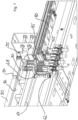
- the support device (33) shown has connecting elements (60) and (61) for the purpose of connection to other support devices of the same design. Since the type of connection of the support devices (33) to form a circulating chain is not important for the invention, these elements will not be discussed further.
- the revolving guidance takes place via the two guide rollers (62) and (63) shown, which interact with stationary guide curves (64), one of which, for example, in figure 7 is recognizable.
- the carrying device (33) has a holding means designed as a clamping mandrel (55).
- This clamping mandrel (55) protrudes with its clamping head into the interior of the mouth area (302) of the preform (1) and then holds the preform (1) due to an exerted clamping force.
- Corresponding clamping mandrels are known in the prior art.
- the support device (33) has a shielding screen (65).
- the clamping mandrel can be pressed downwards against the restoring force of a spring (66) until the mouth area (302) is arranged below the shielding screen (65) and can be gripped, for example, by pliers on the support ring ( 304) or in the area of the support ring (304).
- the clamping mandrel (55) has a longitudinal axis which, in its spatial position, corresponds to the spatial position of the longitudinal axis of the preform (1). Furthermore, the clamping mandrel (55) is rotatably arranged or mounted in the carrying device (33) so that it can be rotated about its longitudinal axis. Since the axis of rotation of the preform (1) and the axis of rotation of the clamping mandrel (55) are congruent in space, rotating the clamping mandrel (55) about its longitudinal axis causes the preform (1) to rotate about its longitudinal axis.
- the clamping mandrel (55) To apply a rotational force to the clamping mandrel (55), the latter has a gear wheel (68) which, as will be explained later, is guided along a stationary counter-structure during the rotation of the carrying device (33) in the heating device (H).
- the clamping mandrel (55) holds the preform (1) at its lower end, while the clamping mandrel (55) has, at its other opposite end, a guide pin (70) arranged at a distance from its longitudinal axis on a lever arm (71), which will also be described later in to be explained interacts with a guide groove.
- the figure 6 and 7 show four chain-like connected support devices (33) from different perspectives, while the other chain links are not shown. Shown are several toothed racks (80), which together form a first positive guidance device.
- the carrying devices (33) run along these toothed racks (80) and the toothed wheel (68) of each of the carrying devices (33) meshes with the toothed profile (82) on a longitudinal side of the toothed rack (80). Because of this relative movement, the clamping mandrels (55) are driven to rotate about their own longitudinal axis.
- the preforms (1) which are held by the clamping mandrels (55), continuously rotate about their own longitudinal axis in the areas provided with toothed racks (80).
- these preforms are in the figure 6 and 7 to simplify the drawing, they are guided along heating boxes (30) which are no longer shown and, as a result of the described uniform rotation, are heated homogeneously in the circumferential direction.
- the figures 6 and 7 further show a second restraining means which interacts with the guide pins (70) of the clamping mandrels (55).
- This interaction is better seen in figure 7 , since this second restraint means is viewed from below.
- the second forced guidance means has a guide groove (92) on its underside facing the clamping mandrel (55), into which the guide pin (70) projects and which therefore specifies the rotational position of the guide pin (70).
- the heating section designated overall by the reference numeral (24) is the area in which the transition from the first forced guidance means to the second forced guidance means takes place.
- the rotational position of the clamping mandrels (55) is initially determined by the toothed racks (80) and the tooth profiles (82) formed on them, into which the teeth of the Gear wheel (68) of the clamping mandrel (55) engage.
- a curved area (95) of the guide groove (92) begins at the left-hand end of the toothed rack (80), since the forced rotary movement of the clamping mandrel (55) also causes the guide pin (70) to rotate.
- the second forced guidance device is equipped with a guide groove (92), which on the one hand has a curved course and on the other hand shows an expanding groove width viewed from left to right, or viewed from right to left narrows in a funnel shape in order to to act as a threading aid for the guide pins (70) of the clamping mandrels (55). It is provided that at all times the rotational position of the clamping mandrel (55) is predetermined by the forced guidance means, namely either by the toothed racks (80) or by the guide groove (92) or by both. In a short transition area, the gear wheel (68) of the clamping mandrel (55) rolls on the toothed structure (82) of the toothed rack (80), while at the same time the guide pin (70) is already guided in the curved guide groove (92).
- restraint means provided in the to figures 6 and 7 shown type can be executed. It is at least provided that the rotational position of the clamping mandrels (55), starting from the transfer area of the preforms (1) from the transfer wheel (29) to the carrying devices (33) up to the removal area, is fixed by restraint means, so that until the preforms (1) are removed the rotational position of the support devices (33) in the area of the removal wheel (35) is fixed by external influences.
- the remaining area along the head wheel (34) between the removal wheel (35) and the input wheel (29) is preferably also provided with restraint means, so that the rotational position of the clamping mandrel (55) is fixed over the entire revolution.
- These second forced guidance means have a threading element (94) for simplified adjustment and alignment between the first forced guidance means in the form of the toothed racks (80) and the second forced guidance means.
- this threading element (94) In its inlet area (95), this threading element (94) has a threading opening which tapers in a funnel shape in the conveying direction and which extends into a curved groove with a narrowing groove width merges and finally opens into a groove of constant width and with groove extension in the conveying direction.
- This threading element (94) is designed separately from an adjoining guide rail (90), which has a guide groove (92) of constant width over its entire length extending in the conveying direction. The threading element (94) can be shifted for adjustment purposes in order to allow the transition and the short-term forced guidance of the clamping mandrel (55) by both forced guidance means without interference and preventing jamming.
- this transition area is also characterized in that a filler piece (85) with short dimensions in the conveying direction is arranged in this area, which leads to a doubling of the tooth height of the rack (80) in this area.
- the toothed rack (80) has identical tooth profiles (82) on its two longitudinal sides.
- the profile of the individual teeth of the tooth profiles (82) is chosen so that both tooth flanks look identical, ie are symmetrical to the tooth center.
- 180° also converts the rack (80) into itself, namely by the in Figure 8a top shown in the top view remains unchanged, but the upper toothed rack (82) becomes the lower toothed rack (82).
- the rack (80) can be installed and used in four different orientations, so that, for example, after a certain period of use, an Wear on the tooth flanks can be absorbed by installing the racks (80) in a rotated manner as described above.
- the illustrated embodiments of the toothed racks (80) advantageously have a hole pattern (84) in their end regions in order to be connected to one another by inserting connecting pins.
- the distance between the holes and the arrangement of the holes in the hole pattern (84) is selected in such a way that when adjacent end areas of toothed racks (80) are placed one on top of the other and when connecting pins are pushed through the holes in toothed racks (80) that are positioned one above the other, their teeth in the toothed profiles (82) that are positioned one above the other are aligned with each other.
- the recesses (86) and incisions (88) formed in the area between the hole patterns (84) arranged at the ends ensure that the toothed rack (80) does not warp during thermal expansion.
- Each of the recesses (86), together with the two associated incisions (88) on both sides, represents a parallelogram made up of flexures.
Abstract
Die Erfindung betrifft Heizverfahren und Heizvorrichtungen (H) zur thermischen Konditionierung von Vorformlingen (1). Vorformlinge werden in einer Förderrichtung durch eine Heizvorrichtung (H) geführt, wobei in der Heizvorrichtung (H) mehrere Heizeinrichtungen (30) stationär und in der Förderrichtung hintereinanderliegend angeordnet werden und wobei das Führen der Vorformlinge (1) entlang der Heizeinrichtungen (30) durch mehrere Trageinrichtungen (33) für Vorformlinge erfolgt, die miteinander verbunden werden zur Ausbildung einer Endlostransportkette. Die Endlostransportkette wird angetrieben zu einem kontinuierlichen Umlauf innerhalb der Heizvorrichtung (H) in Förderrichtung entlang einer Umlaufstrecke, um von den Trageinrichtungen (33) gehaltene Vorformlinge (1) zum Zwecke der thermischen Konditionierung entlang der Heizeinrichtungen (30) zu transportieren. Jede Trageinrichtung (33) ist mit einem Haltemittel (55) für Vorformlinge (1) versehen, das den Vorformling (1) hält und das drehbar in der Trageinrichtung (33) angeordnet wird für eine Drehung des Vorformlings (1) um dessen Längsachse. In einem Zuführbereich der Umlaufstrecke werden den Trageinrichtungen (33) Vorformlinge () zugeführt und von deren Haltemitteln (55) aufgenommen, wobei in einem Entnahmebereich der Umlaufstrecke die temperaturkonditionierten Vorformlinge (1) von den Haltemitteln (55) der Trageinrichtungen (33) abgenommen werden, sodass die Transporteinrichtungen (33) zwischen dem Entnahmebereich und dem Zuführbereich vorformlingslos und zwischen dem Zuführbereich und dem Entnahmebereich vorformlingshaltend umlaufen. Während des vorformlingshaltenden Umlaufs wird in einem ersten Umlaufstreckenteilbereich auf die Drehposition der Haltemittel (55) von einem ersten form- und/oder kraftschlüssig angreifenden Zwangsführungsmittel (80) eingewirkt und in einem zweiten Umlaufstreckenteilbereich auf die Drehposition der Haltemittel (55) von einem zweiten form- und/oder kraftschlüssig angreifenden Zwangsführungsmittel (90) eingewirkt. Das erste Zwangsführungsmittel (80) treibt die Haltemittel (55) so zu einer Drehung an, dass die Vorformlinge (1) beim Führen entlang der Heizeinrichtungen (30) in ihrer Umfangsrichtung gleichmäßig temperiert werden. Die zweiten Zwangsführungsmittel (90) zwangsführen die Drehposition der Haltemittel (55) so, dass die Vorformlinge (1) beim Führen entlang der Heizeinrichtungen (30) in ihrer Umfangsrichtung ungleichmäßig temperiert werden (preferential heating), wobei die ersten und zweiten Zwangsführungsmittel (80, 90) die Drehposition der Haltemittel (55) mindestens so lange zwangsführen, wie die Haltemittel (55) vorformlingshaltend umlaufen, bevorzugt während des gesamten Umlaufs entlang der Umlaufstrecke.The invention relates to heating methods and heating devices (H) for the thermal conditioning of preforms (1). Preforms are guided through a heating device (H) in a conveying direction, with a plurality of heating devices (30) being arranged in the heating device (H) in a stationary manner and one behind the other in the conveying direction, and with the preforms (1) being guided along the heating devices (30) by a plurality of Carrying devices (33) for preforms, which are connected to each other to form an endless transport chain. The endless transport chain is driven to circulate continuously within the heating device (H) in the conveying direction along a circulating path in order to transport preforms (1) held by the carrying devices (33) along the heating devices (30) for the purpose of thermal conditioning. Each support (33) is provided with a preform (1) holding means (55) which holds the preform (1) and which is rotatably mounted in the support (33) for rotation of the preform (1) about its longitudinal axis. In a feed area of the circulating section, preforms () are fed to the carrying devices (33) and picked up by their holding means (55), with the temperature-conditioned preforms (1) being removed from the holding means (55) of the carrying devices (33) in a removal area of the circulating section, so that the transport devices (33) circulate between the removal area and the feed area without a preform and between the feed area and the removal area with a preform. During the rotation that holds the preform, the rotary position of the holding means (55) is acted upon in a first partial area of the rotary path by a first positively and/or non-positively engaging forced guidance means (80), and in a second partial area of the rotary path the rotary position of the holding means (55) is acted upon by a second positive and/or forced guidance means (90) acting in a non-positive manner. The first constraining means (80) drives the holding means (55) to rotate in such a way that the preforms (1) are uniformly temperature-controlled in their circumferential direction as they are guided along the heating devices (30). The second constraining means (90) constrain the rotational position of the holding means (55) in such a way that the preforms (1) are heated unevenly in their circumferential direction when being guided along the heating devices (30) (preferential heating), the first and second constraining means (80, 90) constraining the rotational position of the holding means (55) at least as long as the holding means (55) rotate holding the preform, preferably during the entire rotation along the circulation path.
Description
Die Erfindung betrifft ein Heizverfahren zur thermischen Konditionierung von Vorformlingen, die für eine Umformung vorgesehen sind, nach dem Oberbegriff des Anspruchs 1.The invention relates to a heating method for the thermal conditioning of preforms that are intended for forming, according to the preamble of
Die Erfindung betrifft weiterhin eine Heizvorrichtung zur thermischen Konditionierung von Vorformlingen, die für eine Umformung vorgesehen sind, nach dem Oberbegriff des Anspruchs 5 und eine Behälterherstellungsmaschine nach Anspruch 18 mit einer solchen Heizvorrichtung.The invention further relates to a heating device for the thermal conditioning of preforms which are provided for forming, according to the preamble of claim 5 and a container manufacturing machine according to
Die Erfindung betrifft schließlich Zwangsführungseinrichtungen nach dem Oberbegriff von Anspruch 15 und zur Verwendung in einer Heizvorrichtung für Vorformlinge.Finally, the invention relates to positive guidance devices according to the preamble of claim 15 and for use in a heating device for preforms.
Generell geht es um das Gebiet des Preferential Heating, also um die ungleichmäßige Temperierung von Vorformlingen in deren Umfangsrichtung. Eine derartige ungleichmäßige Temperierung mit stärker erwärmten Umfangsbereichen und mit weniger stark erwärmten Umfangsbereichen wird beispielsweise angewendet, wenn aus den Vorformlingen Behälter hergestellt werden sollen, deren Querschnitt von einer kreisrunden Form abweicht. Die Abweichung kann beispielsweise darin bestehen, dass Behälter mit ovalem Querschnitt oder beispielsweise mit dreieckigem oder viereckigem Querschnitt produziert werden sollen.In general, it is about the field of preferential heating, i.e. about the non-uniform temperature control of preforms in their circumferential direction. Such non-uniform temperature control with more intensely heated peripheral areas and less intensely heated peripheral areas is used, for example, when containers are to be produced from the preforms, the cross section of which deviates from a circular shape. The deviation can consist, for example, in the fact that containers with an oval cross section or, for example, with a triangular or square cross section are to be produced.
Solche Temperierungen sind erforderlich, um Vorformlinge aus einem thermoplastischen Material auf einen nachfolgenden Umformvorgang vorzubereiten, nämlich das thermoplastische Vorformlingsmaterial auf eine Temperatur zu bringen, die eine Umformung erlaubt. Bekannt ist einerseits, dass diese Umformung unter Verwendung eines Blasgases erfolgt. Bekannt ist auch, dass eine simultane Umformung und Befüllung erfolgt, indem das Füllgut als flüssiges Umformfluid unter einem Umformdruck in den zuvor temperierten Vorformling eingeleitet wird. Bezüglich der Temperierung besteht kein grundsätzlicher Unterschied zwischen beiden Umformprozessen, sodass nachfolgend stellvertretend für alle Umformprozesse auf Blasprozesse abgestellt wird, d. h. auf die Verwendung eines Blasgases, um den technischen Hintergrund der Erfindung zu erläutern, ohne dass darin aber eine Beschränkung der Allgemeinheit zu sehen ist, denn die Erfindung befasst sich mit der Temperierung der Vorformlinge und der Führung der Vorformlinge durch Heizvorrichtungen bzw. während der Temperierung, sodass es auf den sich daran anschließenden Umformvorgang bei der Erfindung nicht ankommt.Such tempering is necessary in order to prepare preforms made of a thermoplastic material for a subsequent forming process, namely to bring the thermoplastic preform material to a temperature that allows forming. On the one hand, it is known that this reshaping takes place using a blowing gas. It is also known that simultaneous forming and filling takes place by introducing the filling material as a liquid forming fluid under a forming pressure into the previously temperature-controlled preform. With regard to temperature control, there is no fundamental difference between the two forming processes, so that in the following, blowing processes are used as representative of all forming processes, i. H. to the use of a blowing gas in order to explain the technical background of the invention, but without this being seen as a restriction of generality, because the invention deals with the temperature control of the preforms and the guidance of the preforms through heating devices or during the temperature control, so that the subsequent forming process is not important in the case of the invention.
Bei einer Behälterformung z.B. durch Blasdruckeinwirkung werden Vorformlinge aus einem thermoplastischen Material, beispielsweise Vorformlinge aus PET (Polyethylenterephthalat), innerhalb einer Blasmaschine unterschiedlichen Bearbeitungsstationen zugeführt. Typischerweise weist eine derartige Blasmaschine eine Heizvorrichtung sowie eine Blaseinrichtung auf, in deren Bereich der zuvor temperierte Vorformling durch biaxiale Orientierung zu einem Behälter expandiert wird. Die Expansion erfolgt mit Hilfe von Druckluft, die in den zu expandierenden Vorformling eingeleitet wird. Der verfahrenstechnische Ablauf bei einer derartigen Expansion des Vorformlings wird z.B. in der
Der grundsätzliche Aufbau einer Blasstation zur Behälterformung wird in der
Innerhalb der Vorrichtung zur Blasformung können die Vorformlinge sowie die geblasenen Behälter mit Hilfe unterschiedlicher Handhabungseinrichtungen transportiert werden. Bewährt hat sich insbesondere die Verwendung von Transportdornen, auf die die Vorformlinge aufgesteckt werden. Die Vorformlinge können aber auch mit anderen Trageinrichtungen gehandhabt werden. Die Verwendung von Greifzangen zur Handhabung von Vorformlingen und die Verwendung von Spreizdornen, die zur Halterung in einen Mündungsbereich des Vorformlings einführbar sind, gehören ebenfalls zu den verfügbaren Konstruktionen. Eine Handhabung von Behältern unter Verwendung von Übergaberädern wird beispielsweise in der
Im Hinblick auf die verwendeten Blasstationen sind unterschiedliche Ausführungsformen bekannt. Bei Blasstationen, die auf rotierenden Blasrädern angeordnet sind, ist eine buchartige Aufklappbarkeit der Formträger häufig anzutreffen. Es ist aber auch möglich, relativ zueinander verschiebliche oder andersartig geführte Formträger einzusetzen.With regard to the blow molding stations used, different embodiments are known. In the case of blow-moulding stations that are arranged on rotating blow-moulding wheels, the mold carriers can often be folded up in a book-like manner. However, it is also possible to use mold carriers that are displaceable relative to one another or that are guided in some other way.
Ungeachtet der konkreten Ausgestaltung der Blasstation erfolgt die Herstellung der Behälter aus den Vorformlingen dadurch, dass die Vorformlinge nach ihrer Temperaturkonditionierung den Blasstationen zugeführt und übergeben werden, dass die Vorformlinge dabei in eine geöffnete Form eingesetzt und die Form anschließend geschlossen wird. Durch Beaufschlagen des Vorformlings mit einem Umformmedium unter Druck wird dieser gegen die umgebende äußere Form expandiert, häufig unter Verwendung einer Reckstange, die in Längsrichtung des Vorformlings in diesen hineinfährt und ihn in Längsrichtung reckt und führt.Irrespective of the specific configuration of the blow molding station, the containers are produced from the preforms by the preforms being fed and transferred to the blow molding stations after their temperature conditioning, the preforms being inserted into an open mold and the mold then being closed. By subjecting the preform to a forming medium under pressure, it is expanded against the surrounding outer mold, often using a stretching rod which moves into the preform in the longitudinal direction and stretches and guides it in the longitudinal direction.
Die Herstellung der eingangs erwähnten unrunden Behälter wird bereits in der
Aus der
Weiterhin ist im Stand der Technik bekannt, einen Vorformling zunächst in einem ersten Heizungsabschnitt einer Heizvorrichtung in Umfangsrichtung homogen, das heißt gleichmäßig zu erwärmen, und anschließend in einem zweiten Heizungsabschnitt in Umfangsrichtung das gewünschte Temperaturprofil zu erzeugen. Einen solchen Stand der Technik zeigt die
Die
Die Erzeugung eines Temperaturprofils in Umfangsrichtung macht erforderlich, dass die Drehung der Vorformlinge während der Temperierung in einer geführten Weise erfolgt. Hierzu wird in aller Regel so vorgegangen, dass die Vorformlinge von Haltemitteln gehalten und durch die Heizstrecke geführt werden und diese Haltemittel dann in ihrer Drehorientierung zwangsgeführt werden. Drehung des Haltemittels führt zu einer identischen Drehung des Vorformlings. Für eine in Umfangsrichtung gleichmäßige Temperierung wird dabei regelmäßig so vorgegangen, dass das Haltemittel kontinuierlich in Drehung versetzt wird. Hierzu kann das Haltemittel z.B. über ein Zahnrad verfügen, das an einem Profilstrang, z.B. einem Zahnriemen, entlanggeführt wird. Aufgrund einer Relativgeschwindigkeit zwischen Zahnrad und Profilstrang wird eine zwangsgeführte Drehung des Haltemittels induziert. Für die Erzeugung eines Temperaturprofils in Umfangsrichtung kann dann z.B. das Haltemittel drehfest in einer Drehposition gehalten sein, wie dies z.B. in der
Die gewünschte Erzeugung z.B. ovaler Behälter macht erforderlich, dass die in Umfangsrichtung mit einem Temperaturprofil versehenen Vorformlinge in einer gewünschten Ausrichtung in die Umformstationen übergeben werden. Die auf einer höheren Temperatur befindlichen Bereiche müssen in einer bestimmten Richtung weisend in der umgebenden Form angeordnet werden, damit der entstehende ovale Behälter die gewünschte Wanddickenverteilung und die gewünschten Behältereigenschaften aufweist. Es sind daher im Stand der Technik unterschiedliche Verfahren und Vorrichtungen bekannt, um Vorformlinge nach ihrer Temperierung auszurichten und in dieser ausgerichteten Weise den nachfolgenden Umformstationen zu übergeben.The desired production of e.g. The areas at a higher temperature must be placed in the surrounding mold facing in a specific direction in order for the resulting oval container to have the desired wall thickness distribution and container properties. Various methods and devices are therefore known in the prior art for aligning preforms after they have been tempered and transferring them to the downstream forming stations in this aligned manner.
Die bereits angesprochene
Die gattungsbildende
Insgesamt finden sich im Stand der Technik eine Vielzahl von Lösungen, die aber allesamt noch nicht zu vollkommen zufriedenstellenden Verfahren oder Vorrichtungen für die thermische Konditionierung von Vorformlingen führen.Overall, there are a large number of solutions in the prior art, all of which, however, do not yet lead to completely satisfactory methods or devices for the thermal conditioning of preforms.
Es ist daher die Aufgabe der vorliegenden Erfindung, Heizverfahren und Heizvorrichtungen aufzuzeigen, die die bisherigen Probleme überwinden und die unter anderem überflüssig machen, vorder Übergabe des temperierten Vorformlings in eine Umformstation den Vorformling durch Ausrichtbewegungen oder Ausrichtmittel umorientieren zu müssen. Eine weitere Aufgabe der Erfindung besteht darin, entsprechende Einrichtungen zur Verfügung zu stellen, mit denen diese Aufgabe gelöst wird.It is therefore the object of the present invention to show heating methods and heating devices which overcome the previous problems and which, among other things, make it unnecessary to reorient the preform by aligning movements or aligning means before transferring the temperature-controlled preform to a forming station. A further object of the invention consists in making appropriate devices available with which this object is achieved.
Die Lösung dieser Aufgabe gelingt mit einem Heizverfahren nach Anspruch 1. Erfindungsgemäß ist ein Heizverfahren zur thermischen Konditionierung von Vorformlingen, bei dem die Vorformlinge in grundsätzlich bekannter Weise in einer Förderrichtung durch eine Heizvorrichtung geführt werden. Heizvorrichtungen sind grundsätzlich vielfach im Stand der Technik bekannt und diese weist mehrere stationäre Heizeinrichtungen auf, die in der Förderrichtung hintereinanderliegend angeordnet sind. Diese Heizeinrichtungen können z.B. als sogenannte Heizkästen ausgeführt sein mit Infrarot-Strahlern auf der einen Seite der Vorformlinge und mit Reflektoren auf der gegenüberliegenden Seite der Vorformlinge. Das Führen der Vorformlinge entlang der Heizeinrichtungen erfolgt durch mehrere Trageinrichtungen, die miteinander verbunden werden zur Ausbildung einer Endlostransportkette, die angetrieben wird zu einem Umlauf innerhalb der Heizvorrichtung in Förderrichtung entlang einer Umlaufstrecke, um von den Trageinrichtungen gehaltene Vorformlinge zum Zwecke der thermischen Konditionierung entlang der Heizeinrichtungen zu transportieren. Während des regulären Heizverfahrens, also abseits von Störungen, erfolgt dieser Umlauf in einer kontinuierlichen Art und Weise, d. h. die Kette läuft mit einer bestimmten Geschwindigkeit kontinuierlich entlang der Umlaufstrecke und somit anders als in der
Die anspruchsgemäße Trageinrichtung soll mit einem Haltemittel für Vorformlinge versehen sein, das den Vorformling hält und das drehbar in der Trageinrichtung angeordnet wird für eine Drehung des Vorformlings um dessen Längsachse. Ein solches Haltemittel kann typischerweise z.B. als in die Vorformlingsmündung hineingreifender Haltedorn ausgeführt sein. Solche Haltedorne haben den Vorteil, dass die zu temperierenden Bereiche frei zugänglich sind und eine Übergabe auf diese Haltedorne zum Beispiel durch zangenartige Elemente erfolgen kann.The carrying device according to the claims is to be provided with a holding means for preforms which holds the preform and which is rotatably arranged in the carrying device for rotation of the preform about its longitudinal axis. Such a holding means can typically be designed, for example, as a holding mandrel reaching into the mouth of the preform. Such holding mandrels have the advantage that the areas to be tempered are freely accessible and a transfer to these holding mandrels can take place, for example, by means of tong-like elements.
In einem Zuführbereich der Umlaufstrecke werden den Trageinrichtungen die zu temperierenden Vorformlinge zugeführt und von den Haltemitteln der Trageinrichtungen aufgenommen. In einem Entnahmebereich der Umlaufstrecke werden die temperaturkonditionierten Vorformlinge von den Haltemitteln der Trageinrichtungen abgenommen. Die Transporteinrichtungen laufen also zwischen dem Entnahmebereich und dem Zuführbereich in Förderrichtung vorformlingslos um und zwischen dem Zuführbereich und dem Entnahmebereich vorformlingshaltend um.In a feed area of the circulating section, the preforms to be tempered are fed to the carrying devices and picked up by the holding means of the carrying devices. In a removal area of the circulating section, the temperature-conditioned preforms are removed from the holding means of the carrying devices. The transport devices therefore circulate between the removal area and the feed area in the conveying direction without a preform and between the feed area and the removal area with a preform.
Während des vorformlingshaltenden Umlaufs sollen die Vorformlinge in zwei Streckenbereichen unterschiedlich an den Heizeinrichtungen entlanggeführt werden. In einem ersten Umlaufstreckenteilbereich soll dazu auf die Drehposition der Haltemittel von einem ersten form- und/oder kraftschlüssig angreifenden Zwangsführungsmittel eingewirkt werden. Dieses erste Zwangsführungsmittel soll die Haltemittel so zu einer kontinuierlichen Drehung antreiben, dass die Vorformlinge beim Führen entlang der Heizeinrichtungen in ihrer Umfangsrichtung gleichmäßig temperiert werden,During the circulation that holds the preform, the preforms are to be guided differently along the heating devices in two sections. In a first sub-area of the circulating path, the rotational position of the holding means is to be acted on by a first forced guidance means acting in a form-fitting and/or non-positive manner. This first constraining means is intended to drive the holding means into continuous rotation in such a way that the preforms are uniformly temperature-controlled in their circumferential direction as they are guided along the heating devices,
In einem zweiten Umlaufstreckenteilbereich soll auf die Drehposition der Haltemittel von einem zweiten form- und/oder kraftschlüssig angreifenden Zwangsführungsmittel eingewirkt werden. Das zweite Zwangsführungsmittel sollen die Drehposition der Haltemittel so zwangsführen, dass die Vorformlinge beim Führen entlang der Heizeinrichtungen in ihrer Umfangsrichtung ungleichmäßig temperiert werden (preferential heating).In a second sub-area of the circulating path, the rotary position of the holding means is to be acted upon by a second positive-locking and/or non-positively engaging positive guidance means. The second constraining means are intended to constrain the rotational position of the holding means in such a way that the preforms are heated unevenly in their circumferential direction when being guided along the heating devices (preferential heating).
Erfindungsgemäß sollen die ersten und zweiten Zwangsführungsmittel die Drehposition der Haltemittel mindestens so lange zwangsführen, wie die Haltemittel vorformlingshaltend umlaufen. Damit ist gemeint, dass spätestens ab dem Zeitpunkt der Übergabe der Vorformlinge auf die Haltemittel bis zu dem Zeitpunkt des Abnehmens der Vorformlinge von den Haltemitteln eine ununterbrochene Zwangsführung der Drehposition der Haltemittel erfolgt, sodass stets die Ausrichtung der Vorformlinge über die stets definierte Drehposition der Haltemittel bekannt und gewährleistet ist. Auf diese Weise ist nicht erforderlich, dass vor der Übergabe in eine Umformstation eine Ausrichtung der temperierten Vorformlinge erfolgen muss.According to the invention, the first and second restraining means should restrain the rotational position of the holding means at least as long as the holding means rotate while holding the preform. This means that at the latest from the point in time at which the preforms are transferred to the holding means until the point at which the preforms are removed from the holding means, there is an uninterrupted forced guidance of the rotational position of the holding means, so that the orientation of the preforms is always known via the always defined rotational position of the holding means and is guaranteed. In this way, it is not necessary for the temperature-controlled preforms to be aligned before they are transferred to a forming station.
Bevorzugt wird die Drehposition der Haltemittel während des gesamten Umlaufs entlang der Umlaufstrecke zwangsgeführt, also auch während des vorformlingslosen Umlaufs. Damit laufen die Haltemittel in keinem Bereich frei von Zwangsmitteln um, d.h. ihre Drehorientierung ist immer definiert, da durch die Zwangsführungsmittel vorgegeben.The rotational position of the holding means is preferably positively guided during the entire circulation along the circulation path, ie also during circulation without a preform. In this way, the holding means do not revolve freely in any area, ie their rotational orientation is always defined because it is predetermined by the forced guidance means.
Für die erfindungsgemäße unterbrechungslose Festlegung der Drehorientierung der Haltemittel zumindest zu den Zeiten, zu denen diese Vorformlinge halten, können die Übergangsbereiche zwischen dem ersten und dem zweiten Zwangsführungsmittel kritisch sein. Es wird daher mit Vorteil vorgeschlagen, dass in einem Überlappbereich zwischen dem ersten und dem zweiten Zwangsführungsmittel beide Zwangsführungsmittel gleichzeitig auf die Drehposition der Haltemittel einwirken. In diesem Bereich liegt dann zwar eine Überbestimmung vor, es wird aber zuverlässig ein Bereich vermieden, indem keine Zwangsführung erfolgt. In einem konkreten Ausführungsbeispiel kann z.B. eines der Zwangsführungsmittel eine Führungsnut sein, die einen Führungsstift führt. Über die Breite der Führungsnut lässt sich eine Führungstoleranz einstellen und diese Breite der Führungsnut kann z.B. in dem besagten Überlappbereich gegenüber den anderen Umlaufbereichen etwas größer ausgeführt werden, damit ohne gegenseitige Störung oder Blockade beide Zwangsführungsmittel auf das Haltemittel einwirken können. Anderenfalls bzw. alternativ wäre erhöhter Aufwand bei der Justierung und Montage der Zwangsführungsmittel zu betreiben.The transition areas between the first and the second restraint means can be critical for the uninterrupted fixing of the rotational orientation of the holding means according to the invention, at least at the times when these preforms are holding. It is therefore advantageously proposed that in an overlapping area between the first and second forced guidance means, both forced guidance means act simultaneously on the rotational position of the holding means. Although there is overdetermination in this area, an area is reliably avoided in which there is no forced guidance. In a specific embodiment, for example, one of the forced guidance means can be a guide groove that guides a guide pin. A guide tolerance can be set via the width of the guide groove and this width of the guide groove can be made slightly larger in the said overlapping area compared to the other circumferential areas, so that both forced guidance means can act on the holding means without mutual interference or blockage. Otherwise, or alternatively, increased effort would have to be expended in adjusting and assembling the positive guidance means.
In einer bevorzugten Ausführungsvariante der Erfindung, die bezüglich Montageaufwand und Kosten als vorteilhaft angesehen wird, ist ein Mitnehmer am Haltemittel angeordnet und dieser wird entlang einer stationären Führungskurve geführt. Dabei ist eine beidseitige Führung des Mitnehmers eine weiter bevorzugt Untervariante, d. h. der Mitnehmer wird von beiden Seiten von einer Führungskurve in seiner Drehposition festgelegt. Dies lässt sich z.B. in bevorzugter Weise realisieren durch eine Führungsnut in einem Führungskörper, wobei der Mitnehmer dabei z.B. als Mitnehmerstift ausgeformt ist, der in die Führungsnut hereinragt. Alternativ ließe sich die Anordnung des Mitnehmers und der Führungskurve auch umkehren, d. h. das Haltemittel weist nicht den Mitnehmer bzw. den Mitnehmerstift auf, sondern eine Führungsfläche, die der Führungskurve entspricht, bzw. einen Führungsschlitz, der der Führungsnut entspricht, die mit stationär angeordneten Gegenflächen bzw. einer stationär angeordneten Führungsschiene zusammenwirkt. Diese alternativen Varianten werden aber als weniger vorteilhaft angesehen. Bei allen diesen genannten Ausführungsvarianten, aber auch unabhängig davon, wird als vorteilhaft angesehen, dass die ersten Zwangsführungsmittel mit einem Drehantriebskörper, typischerweise einem Zahnrad, am Haltemittel kämmen. Solche mit Zahnrädern kämmende Mittel sind im Stand der Technik grundsätzlich bekannt und sind z.B. als Zahnriemen oder Ketten ausgeführt.In a preferred embodiment of the invention, which is considered advantageous in terms of assembly effort and costs, a driver is arranged on the holding means and this is guided along a stationary guide curve. In this case, guiding the driver on both sides is a further preferred sub-variant, d. H. the driver is fixed in its rotational position on both sides by a guide curve. This can be implemented in a preferred manner, for example, by a guide groove in a guide body, with the driver being formed, for example, as a driver pin that protrudes into the guide groove. Alternatively, the arrangement of the driver and the guide curve could also be reversed, i. H. the holding means does not have the driver or the driver pin, but rather a guide surface which corresponds to the guide curve or a guide slot which corresponds to the guide groove which interacts with stationary mating surfaces or a stationary guide rail. However, these alternative variants are considered to be less advantageous. In all of these design variants mentioned, but also independently of them, it is considered advantageous that the first positive guidance means mesh with a rotary drive body, typically a gear wheel, on the holding means. Such means meshing with toothed wheels are basically known in the state of the art and are designed, for example, as toothed belts or chains.
Als gegenüber diesen genannten Zahnriemen oder Ketten bevorzugte Ausführungsform wird vorgeschlagen, dass die ersten Zwangsführungsmittel als mehrere in Förderrichtung hintereinander angeordnete Zahnstangen ausgeführt sind, die mit dem Zahnrad kämmen. Der Begriff "Zahnstange" ist technisch üblich und bekannt, und Zahnstangen sind im Stand der Technik in großer Variationsbreite bekannt. Ein Charakteristikum von Zahnstangen ist, dass diese eine Längserstreckung aufweisen und an ihren Längsseiten ein Zahnprofil aufweisen, in das Gegenverzahnungen, z.B. von Zahnrädern, eingreifen können. Zahnstangen sind in aller Regel dabei als starre Körper ausgeführt. Das Vorsehen mehrerer Zahnstangen ergibt den Vorteil einer Modularität und Anpassbarkeit. Insbesondere bei Anordnung der Zahnstangen mit teilweiser Überlappung in deren Längsrichtung kann z.B. eine Standardlänge verwendet werden, um jede gewünschte Länge des Bereiches abzudecken, in dem eine Drehung der Vorformlinge gewünscht ist, nämlich durch geeignete Wahl der Anzahl der Zahnstangen und der Überlapplänge. Gegenüber Zahnriemen erscheinen solche Zahnstangen vorzugswürdig, da bei einem Zahnriemen hohe Anforderungen an den Zahnriemenantrieb und an die Zahnriemenspannung gestellt würden, denn dieser Zahnriemen müsste eine phasengenaue und eine phasengeschwindigkeitsgenaue Übergabe ermöglichen im Übergang zu den zweiten Zwangsführungsmitteln.As an embodiment that is preferred over these named toothed belts or chains, it is proposed that the first positive guidance means be designed as a plurality of toothed racks arranged one behind the other in the conveying direction and meshing with the gear wheel. The term "gear rack" is technically common and known, and gear racks are known in the prior art in a wide range of variations. A characteristic of toothed racks is that they have a longitudinal extent and have a tooth profile on their longitudinal sides, into which counter-toothing, for example of gear wheels, can engage. racks are usually designed as rigid bodies. The provision of multiple racks gives the advantage of modularity and adaptability. Particularly when arranging the racks with partial overlapping in their longitudinal direction, for example, a standard length can be used to cover any desired length of the area where rotation of the preforms is desired, by appropriate choice of the number of racks and the overlap length. Such toothed racks appear to be preferable to toothed belts, since a toothed belt would place high demands on the toothed belt drive and the toothed belt tension, because this toothed belt would have to enable a phase-accurate and phase-speed-accurate transfer in the transition to the second forced guidance means.
Die Lösung der gestellten Aufgabe gelingt auch mit einer Heizvorrichtung mit den Merkmalen des Anspruchs 5. Analog zum vorstehend beschriebenen Verfahren ist eine Heizvorrichtung für die thermische Konditionierung von Vorformlingen erfindungsgemäß, durch die Vorformlinge zum Zwecke ihrer Temperaturkonditionierung in einer Förderrichtung geführt werden, wobei in der Heizvorrichtung mehrere Heizeinrichtungen stationär und in der Förderrichtung hintereinanderliegend angeordnet sind. Die Heizvorrichtung weist mehrere Trageinrichtungen für Vorformlinge auf, die miteinander verbunden sind zur Ausbildung einer Endlostransportkette, wobei die Endlostransportkette antreibbar ist, z.B. durch Verbindung mit einen Antriebsmotor, zu einem kontinuierlichen Umlauf innerhalb der Heizvorrichtung in Förderrichtung und entlang einer Umlaufstrecke. Bei diesem Umlauf entlang der Umlaufstrecke erfolgt das Führen der Vorformlinge entlang der Heizeinrichtungen, wobei jede Trageinrichtung ein Haltemittel für Vorformlinge aufweist, das ausgebildet ist für das Halten des Vorformlings, z.B. und bevorzugt ein Haltedorn, der in den Mündungsbereich des Vorformlings hineingreift und den Vorformling z.B. klemmend hält, Das Haltemittel ist drehbar in der Trageinrichtung angeordnet für eine Drehung des gehaltenen Vorformlings um dessen Längsachse. Die Heizvorrichtung weist einen Zuführbereich für Vorformlinge auf, in dem den Trageinrichtungen Vorformlinge zuführbar sind und in dem von den Haltemitteln Vorformlinge aufnehmbar sind und aufgenommen werden. Die Heizvorrichtung weist weiterhin einen Entnahmebereich auf, in dem die temperaturkonditionierten Vorformlinge von den Haltemitteln der Trageinrichtungen abnehmbar sind und abgenommen werden, sodass im Betrieb der Heizvorrichtung die Transporteinrichtungen mit ihren Haltemitteln zwischen dem Entnahmebereich und dem Zuführbereich ohne Vorformlinge, also vorformlingslos, und zwischen dem Zuführbereich und dem Entnahmebereich mit Vorformlingen, also vorformlingshaltend umlaufen. Die Heizvorrichtung weist erste und zweite formund/oder kraftschlüssig an den Haltemitteln angreifende und deren Drehposition vorgebende Zwangsführungsmittel auf, die beide zumindest in dem Umlaufbereich angeordnet sind, in dem die Transporteinrichtungen vorformlingshaltend umlaufen. Das erste Zwangsführungsmittel ist ausgebildet, die Haltemittel so zu einer gleichförmigen und in der Regel kontinuierlichen Drehung um deren Längsachse anzutreiben, dass die Vorformlinge beim Führen entlang der Heizeinrichtungen in ihrer Umfangsrichtung gleichmäßig temperiert werden. Die zweiten Zwangsführungsmittel sind so ausgebildet, die Drehposition der Haltemittel so zwangszuführen, dass die Vorformlinge beim Führen entlang der Heizeinrichtungen in ihrer Umfangsrichtung ungleichmäßig temperiert werden (preferential heating). Dabei sind die ersten und die zweiten Zwangsführungsmittel so angeordnet und weisen eine solche Erstreckung auf, dass die Drehposition der Haltemittel in Förderrichtung wenigstens vom Zuführbereich bis zum Entnahmebereich durch die beiden Zwangsführungsmittel vorgeben ist, bevorzugt entlang der gesamten Umlaufstrecke. Wie auch zum Verfahrensanspruch erläutert, soll erfindungsgemäß von den ersten und zweiten Zwangsführungsmitteln die Drehposition der Haltemittel mindestens so lange zwangsgeführt werden, wie die Haltemittel vorformlingshaltend umlaufen. Spätestens ab dem Zeitpunkt der Übergabe der Vorformlinge auf die Haltemittel bis zu dem Zeitpunkt des Abnehmens der Vorformlinge von den Haltemitteln soll eine ununterbrochene Zwangsführung der Drehposition der Haltemittel erfolgen, wodurch stets die Ausrichtung der Vorformlinge über die stets definierte Drehposition der Haltemittel bekannt und gewährleistet ist. Auf diese Weise ist nicht erforderlich, dass vor der Übergabe in eine Umformstation eine Ausrichtung der temperierten Vorformlinge erfolgen muss.The object set is also achieved with a heating device having the features of claim 5. Analogously to the method described above, a heating device for the thermal conditioning of preforms is according to the invention, through which the preforms are guided in a conveying direction for the purpose of their temperature conditioning, wherein in the heating device several heating devices are arranged stationary and one behind the other in the conveying direction. The heating device has several carrier devices for preforms, which are connected to one another to form an endless transport chain, the endless transport chain being drivable, for example by being connected to a drive motor, for continuous circulation within the heating device in the conveying direction and along a circulation path. During this circulation along the circulation path, the preforms are guided along the heating devices, with each carrying device having a holding means for preforms which is designed to hold the preform, for example and preferably a holding mandrel which engages in the mouth area of the preform and holds the preform, for example holding by clamping. The holding means is rotatably arranged in the carrying device for rotation of the held preform about its longitudinal axis. The heating device has a feed area for preforms, in which preforms can be fed to the carrying devices and in which preforms can and are received by the holding means. The heating device also has a removal area in which the temperature-conditioned preforms can be removed from the holding means of the carrying devices and are removed, so that during operation of the heating device the transport devices with their holding means between the removal area and the feed area without preforms, i.e. without preforms, and between the feed area and the removal area with preforms, i.e. circulate while holding the preforms. The heating device has first and second constrained guidance means which engage positively and/or non-positively on the holding means and determine their rotational position, both of which are arranged at least in the circulating area in which the transport devices circulate while holding the preform. The first forced guidance means is designed to drive the holding means to rotate uniformly and generally continuously about their longitudinal axis in such a way that the preforms are uniformly temperature-controlled in their circumferential direction as they are guided along the heating devices. The second constraining means are designed so that the rotational position of the holding means in such a way that the preforms are heated unevenly in their circumferential direction when they are guided along the heating devices (preferential heating). The first and second forced guidance means are arranged and have such an extension that the rotational position of the holding means in the conveying direction is specified by the two forced guidance means at least from the feed area to the removal area, preferably along the entire circulating path. As also explained with regard to the method claim, according to the invention the rotational position of the holding means is to be forcibly guided by the first and second forced guidance means at least as long as the holding means rotate holding the preform. At the latest from the point at which the preforms are transferred to the holding means until the point at which the preforms are removed from the holding means, there should be uninterrupted forced guidance of the rotational position of the holding means, whereby the alignment of the preforms via the always defined rotational position of the holding means is always known and guaranteed. In this way, it is not necessary for the temperature-controlled preforms to be aligned before they are transferred to a forming station.
Bevorzugt wird die Drehposition der Haltemittel während des gesamten Umlaufs entlang der Umlaufstrecke zwangsgeführt, also auch während des vorformlingslosen Umlaufs. Damit laufen die Haltemittel in keinem Bereich frei von Zwangsmitteln um, d.h. ihre Drehorientierung ist immer definiert, da durch die Zwangsführungsmittel vorgegeben.The rotational position of the holding means is preferably positively guided during the entire circulation along the circulation path, ie also during circulation without a preform. In this way, the holding means do not revolve freely in any area, i.e. their rotational orientation is always defined, since this is predetermined by the forced guidance means.
Weitere vorteilhafte Ausführungsformen sind in den Unteransprüchen angegeben, deren Vorteile sich teilweise bereits aus den analogen und schon besprochenen vorteilhaften Ausführungsformen des Verfahrens ergeben.Further advantageous embodiments are specified in the dependent claims, some of the advantages of which already result from the analogous and already discussed advantageous embodiments of the method.
Als besonders bevorzugte Ausführungsvariante zu den Zahnstangen wird angesehen, dass beide Längsseiten der Zahnstangen mit einem Zahnprofil für den kämmenden Eingriff mit einem Zahnrad versehen sind, wobei die beiden Längsseiten durch eine Drehung der Zahnstange um 180 Grad ineinander überführbar sind. Die Zahnstange ist dadurch möglichst langlebig benutzbar, denn sie kann beidseitig benutzt werden, da auf beiden Längsseiten ein Zahnprofil ausgebildet ist. Ist z.B. das Zahnprofil auf der einen Seite bereits deutlich abgenutzt, so kann durch schlichtes Drehen der Zahnstange um 180° diese weiter benutzt werden.A particularly preferred embodiment of the toothed racks is that both longitudinal sides of the toothed racks are provided with a tooth profile for meshing engagement with a gear wheel, with the two longitudinal sides being convertible into one another by rotating the toothed rack by 180 degrees. As a result, the toothed rack can be used for as long a period as possible because it can be used on both sides, since a tooth profile is formed on both long sides. If, for example, the tooth profile is already clearly worn on one side, you can continue to use it by simply turning the toothed rack by 180°.
Es wird weiterhin mit Vorteil vorgeschlagen, dass die Zähne des Zahnprofils der Zahnstangen zu beiden Seiten identische Zahnflanken aufweisen. In aller Regel wird nur eine der beiden Zahnflanken intensiv beansprucht, während die andere weniger beansprucht wird. Dies ist bedingt durch die stets gleichbleibende Förderrichtung, die zu dieser einseitig stärkeren Belastung der Zähne führt. Bei Vorliegen symmetrischer Zähne sind beide Zahnflanken nutzbar. Es ist also möglich, die Zahnstange so zu drehen, dass die bisher kaum abgenutzten Zahnflanken nunmehr zu intensiv beanspruchten Zahnflanken werden. Insbesondere zusammen mit dem Vorsehen von Zahnprofilen auf beiden Längsseiten kann insgesamt die Zahnstange vierfach genutzt werden, was zu einer erheblichen Verlängerung der Nutzungsdauer führt.It is also advantageously proposed that the teeth of the tooth profile of the toothed racks have identical tooth flanks on both sides. As a rule, only one of the two tooth flanks is subjected to intense stress, while the other is less stressed. This is due to the conveying direction always remaining the same, which leads to this stronger one-sided load on the teeth. If the teeth are symmetrical, both tooth flanks can be used. It is therefore possible to turn the toothed rack in such a way that the tooth flanks, which have hardly been worn up to now, now become heavily stressed tooth flanks. In particular together with the provision of tooth profiles on both longitudinal sides, the toothed rack can be used four times, which leads to a considerable extension of the service life.
Es wird weiterhin mit Vorteil vorgeschlagen, dass die Zahnstange aus einem Kunststoff hergestellt ist. Das mit der Zahnstange kämmende Gegenelement, z.B. ein Zahnrad, kann dann aus einem Metall oder einem anderen harten Material ausgeführt werden und insofern tritt Verschleiß an der Kunststoffzahnstange auf, die aber leichter austauschbar ist, als eine Transporteinrichtung aus einer Endloskette. Geeignete Kunststoffe sind dem Fachmann bekannt, z.B. PEEK oder PTFE.It is also advantageously proposed that the toothed rack is made from a plastic. The counter element meshing with the toothed rack, e.g. a toothed wheel, can then be made of metal or another hard material and in this respect wear occurs on the plastic toothed rack, which, however, is easier to replace than a transport device made of an endless chain. Suitable plastics are known to those skilled in the art, e.g. PEEK or PTFE.
Aus Gründen einfacher Montage und einfacher Ausrichtung der Zahnstangen zueinander wird mit Vorteil vorgeschlagen, dass in beiden stirnseitigen Endbereichen der Zahnstangen jeweils Lochmuster mit jeweils wenigstens einer, bevorzugt mehreren sich in Längsrichtung erstreckenden Lochreihen ausgebildet sind. Die Löcher der Lochreihe sollen sich von einer Ober- zu einer Unterseite der Zahnstange durch die Zahnstange hindurch erstrecken. Mittels Stiften lassen sich dann Zahnstangen verbinden, indem die Löcher zueinander fluchtend übereinandergelegt werden. Der Lochabstand innerhalb einer Lochreihe soll dabei bevorzugt dem Zahnabstand des Zahnprofils oder einem mehrfachen davon entsprechen, wobei die Lochmuster so angeordnet sind, dass bei einem Übereinanderlegen eines Endbereichs einer ersten Zahnstange mit einem Endbereich einer zweiten Zahnstange und bei fluchtender Anordnung der Lochmuster auch die Zähne der sich überlappenden Zahnprofile der übereinandergelegten Zahnstangenbereiche fluchten. Diese in den Endbereichen angeordneten Lochmuster sorgen also nicht nur für eine leichte Verbindbarkeit der Zahnstangen, sondern auch dafür, dass die übereinanderliegenden Zähne fluchten.For reasons of simple assembly and simple alignment of the toothed racks to one another, it is advantageously proposed that hole patterns each with at least one, preferably several rows of holes extending in the longitudinal direction are formed in both end regions of the toothed racks. The holes of the row of holes should extend through the rack from a top to a bottom of the rack. Racks can then be connected by means of pins, in that the holes are aligned one on top of the other. The hole spacing within a row of holes should preferably correspond to the tooth spacing of the tooth profile or a multiple thereof, with the hole patterns being arranged in such a way that when an end area of a first toothed rack is superimposed on an end area of a second toothed rack and when the hole pattern is aligned, the teeth of the overlapping tooth profiles of the superimposed rack areas are aligned. These hole patterns arranged in the end areas not only ensure that the toothed racks can be easily connected, but also that the teeth lying on top of one another are aligned.
Die Zahnstangen werden im Bereich der Heizeinrichtungen angeordnet und erfahren deshalb Temperaturveränderungen. Es wird deshalb mit Vorteil vorgeschlagen, dass sie sich von ihrer Ober- zur Unterseite erstreckende Ausnehmungen sowie zu beiden Seiten der Ausnehmungen Einschnitte aufweisen, die angeordnet und ausgebildet sind, zusammen ein Parallelogramm aus Festkörpergelenken zu bilden. Auf diese Weise bleibt trotz Ausdehnung und Verkürzung durch Temperaturwechsel die Geradheit der Zahnstangen erhalten.The racks are arranged in the area of the heating devices and therefore experience temperature changes. It is therefore advantageously proposed that they have recesses extending from their upper side to their lower side and incisions on both sides of the recesses, which are arranged and designed to form a parallelogram of solid-state joints together. In this way, the racks remain straight despite expansion and contraction due to temperature changes.
Ein geeignetes Mittel zur Lösung der gestellten Aufgaben stellt eine Zwangsführungseinrichtung mit den Merkmalen des Anspruchs 15 dar. Die Zwangsführungseinrichtung ist vorgesehen zur Verwendung in einer Heizvorrichtung für Vorformlinge und für den kämmenden Eingriff mit einem Zahnrad bei dessen Führung entlang der Zwangsführungseinrichtung. Die Zwangsführungseinrichtung weist mehrere Zahnstangen auf und weist im Übrigen die Merkmale auf, die zuvor zu den Zahnstangen angesprochen wurden. Bezüglich der mehrteiligen Ausführung ist dadurch ein modularer Aufbau möglich. Je nach Heizungsgröße wird z.B. eine unterschiedliche Anzahl an Heizkästen verwendet wird, sowohl für die in Umfangsrichtung gleichmäßige Temperierung als auch für "preferential heating". Der modulare Aufbau ist aus Kostengründen und aus Flexibilitätsgründen vorteilhaft. Auch unter dem Aspekt des Austauschs ergeben sich Vorteile.A suitable means for solving the stated tasks is a forced guidance device with the features of claim 15. The forced guidance device is provided for use in a heating device for preforms and for meshing engagement with a gear when it is guided along the forced guidance device. The forced guidance device has a plurality of toothed racks and otherwise has the features that were previously addressed with regard to the toothed racks. With regard to the multi-part design, a modular design is possible as a result. Depending on the size of the heater, for example, a different number of heater boxes is used, both for the uniform temperature control in the circumferential direction as well as for "preferential heating". The modular structure is advantageous for cost reasons and for reasons of flexibility. There are also advantages in terms of exchange.
Als weitere vorteilhafte Ausführungsvariante wird vorgeschlagen, dass die Zwangsführungseinrichtung wenigstens zwei Arten von Zahnstangen aufweist, nämlich eine erste Art mit einer ersten Länge und eine zweite Art mit einer deutlich geringeren Länge, wobei diese geringere Länge weniger als 50 %, bevorzugt weniger als 25 %, der ersten Länge beträgt. Diese Zahnstangen der zweiten Art werden vollständig mit Zahnstangen der ersten Art überlappend angeordnet zur Verdopplung der Zahnhöhe in diesem Bereich, der z.B. ein besonders belasteter Bereich sein kann, z.B. der Überlappbereich zwischen erster und zweiter Zwangsführungseinrichtung. Die Lebensdauer der Zahnstangen der ersten Art kann dadurch erhöht werden. Voraussetzung ist natürlich, dass das Zahnrad, das mit den Zahnstangen kämmt, eine entsprechende Ausdehnung in Achslänge des Vorformlings bzw. des Haltemittels hat, um mit den beiden übereinander angeordneten Zähnen gleichzeitig in Berührung zu kommen.As a further advantageous embodiment variant, it is proposed that the forced guidance device has at least two types of toothed racks, namely a first type with a first length and a second type with a significantly shorter length, this shorter length being less than 50%, preferably less than 25%. of the first length. These racks of the second type are completely overlapped with racks of the first type to double the tooth height in this area, which may be a particularly stressed area, e.g., the overlap area between the first and second restraining means. The service life of the racks of the first type can be increased as a result. The prerequisite is, of course, that the gear wheel that meshes with the toothed racks has a corresponding extension in the axial length of the preform or the holding means in order to come into contact with the two teeth arranged one above the other at the same time.
Aus ähnlichen Gründen erweist es sich als vorteilhaft, dass benachbarte Zahnstangen wenigstens teilweise überlappend angeordnet werden, sodass in diesem Überlappbereich die Zahnhöhe verdoppelt ist. Zudem ist dies vorteilhaft, weil dadurch eine gewisse Längenvariabilität besteht. Über das vorgegebene Lochbild und über dessen Korrelation mit den randseitigen Zähnen ist eine leichte Montierbarkeit gewährleistet.For similar reasons, it has proven to be advantageous for adjacent toothed racks to be arranged so that they overlap at least partially, so that the tooth height is doubled in this overlapping area. In addition, this is advantageous because it results in a certain length variability. Easy assembly is ensured via the specified hole pattern and its correlation with the peripheral teeth.
Schließlich ist erfindungsgemäß eine Behälterherstellungsmaschine für die Umformung von Vorformlingen in Behälter, welche gekennzeichnet ist durch eine Heizvorrichtung nach einer der vorstehend beschriebenen Ausführungsformen und/oder gekennzeichnet durch eine Zwangsführungseinrichtung nach irgendeiner der vorstehend beschriebenen Ausführungsformen. Diese Behälterherstellungsmaschine kann insbesondere eine Blasmaschine sein. Der Begriff der Blasmaschine meint auch solche Maschinen, in denen ein Recken der Vorformlinge z.B. mit einer Reckstange während der Einleitung von Blasgas oder von einem anderen Blasmedium zur blasformenden Umwandlung erfolgt. Alternativ kann die Behälterherstellungsmaschine auch eine solche Maschine sein, bei der die Vorformlinge durch ein flüssiges Umformmedium umgeformt werden, z.B. durch das Füllgut, das in dem Behälter verbleiben soll.Finally, according to the invention, there is a container manufacturing machine for forming preforms into containers, which is characterized by a heating device according to one of the embodiments described above and/or characterized by a positive guidance device according to any of the embodiments described above. This container manufacturing machine can in particular be a blow molding machine. The term blow molding machine also refers to machines in which the preforms are stretched, e.g. with a stretching rod, while blowing gas or another blowing medium is introduced for the blow molding conversion. Alternatively, the container manufacturing machine can also be a machine in which the preforms are shaped by a liquid shaping medium, e.g. by the filling material that is to remain in the container.
In Verbindung mit den nachfolgenden Figuren soll die Erfindung näher erläutert werden anhand von Ausführungsbeispielen. Es zeigen:
- Fig. 1
- eine Skizze zur Veranschaulichung eines grundsätzlichen Aufbaus einer Vorrichtung zur Blasformung von Behältern,
- Fig. 2
- einen Vorformling in einem Längsschnitt,
- Fig. 3
- einen Querschnitt durch eine Anordnung eines Vorformlings im Bereich eines Heizstrahlers,
- Fig. 4
- eine schematische Ansicht, die einen temperierten Vorformling zeigt,
- Fig. 5
- ein Beispiel für eine Trageinrichtung mit Haltemittel mit einem davon gehaltenen Vorformling in zwei unterschiedlichen Ansichten;
- Fig. 6
- einen Teilausschnitt eines Ausführungsbeispiels mit ersten und zweiten Zwangsführungsmitteln
- Fig. 7
- das Ausführungsbeispiel aus
Fig. 6 in einer anderen Ansicht; und - Fig. 8a, 8b
- ein bevorzugtes Ausführungsbeispiel einer Zahnstange in zwei unterschiedlichen Ansichtsperspektiven.
- 1
- a sketch to illustrate a basic structure of a device for blow molding containers,
- 2
- a preform in a longitudinal section,
- 3
- a cross section through an arrangement of a preform in the area of a radiant heater,
- 4
- a schematic view showing a tempered preform,
- figure 5
- an example of a carrying device with holding means with a preform held by it in two different views;
- 6
- a partial section of an embodiment with first and second restraint means
- 7
- the exemplary embodiment
6 in another view; and - Figures 8a, 8b
- a preferred embodiment of a rack in two different perspectives.
Nachfolgend wird zunächst der grundsätzliche Aufbau einer Maschine zur Umformung von Vorformlingen (1) in Behälter erläutert, z.B. in Flaschen, wobei dies am Beispiel einer Blasmaschine erfolgt. Der grundsätzliche Aufbau bliebe aber unverändert, wenn die Umformung der Vorformlinge (1) in Behälter nicht durch Blasluft erfolgte, sondern eine simultane Umformung und Befüllung mit Füllgut erfolgen würde. Insbesondere die Heizung H mit der Heizstrecke (24) bedürfte hierfür keiner Änderungen, denn unabhängig vom verwendeten Umformmedium ist der Vorformling (1) auf die erforderliche Umformungstemperatur zu erwärmen und ist dem Vorformling (1) ein geeignetes Temperaturprofil aufzuprägen.In the following, the basic structure of a machine for forming preforms (1) into containers, e.g. into bottles, is first explained, using a blow molding machine as an example. However, the basic structure would remain unchanged if the preforms (1) were not formed into containers by blowing air, but instead were formed and filled with filling material simultaneously. In particular, the heater H with the heating section (24) does not require any changes, because regardless of the forming medium used, the preform (1) must be heated to the required forming temperature and the preform (1) must be given a suitable temperature profile.
Um einen Vorformling (1) derart in einen Behälter umformen zu können, dass der Behälter Materialeigenschaften aufweist, die eine lange Verwendungsfähigkeit von innerhalb des Behälters abgefüllten Lebensmitteln, insbesondere von Getränken, gewährleisten, müssen spezielle Verfahrensschritte bei der Beheizung und Orientierung der Vorformlinge (1) eingehalten werden. Darüber hinaus können vorteilhafte Wirkungen durch Einhaltung spezieller Dimensionierungsvorschriften erzielt werden.In order to be able to shape a preform (1) into a container in such a way that the container has material properties that ensure that foodstuffs, in particular beverages, filled inside the container can be used for a long time, special process steps must be carried out during the heating and orientation of the preforms (1) be respected. In addition, advantageous effects can be achieved by adhering to special dimensioning regulations.
Als thermoplastisches Material können unterschiedliche Kunststoffe verwendet werden. Einsatzfähig sind beispielsweise PET, PEN oder PP.Different plastics can be used as the thermoplastic material. PET, PEN or PP, for example, can be used.
Die Expansion des Vorformlings (1) während des Orientierungsvorganges erfolgt im gewählten Beispiel durch Druckluftzuführung. Die Druckluftzuführung ist z.B. in eine Vorblasphase, in der Gas, zum Beispiel Pressluft, mit einem niedrigen Druckniveau zugeführt wird, und in eine sich anschließende Hauptblasphase unterteilt, in der Gas mit einem höheren Druckniveau zugeführt wird. Während der Vorblasphase wird typischerweise Druckluft mit einem Druck im Intervall von 10 bar bis 25 bar verwendet und während der Hauptblasphase wird Druckluft mit einem Druck im Intervall von 25 bar bis 40 bar zugeführt.The expansion of the preform (1) during the orientation process takes place in the selected example by compressed air supply. The supply of compressed air is divided, for example, into a pre-blowing phase, in which gas, for example compressed air, is supplied at a low pressure level, and a subsequent main blowing phase, in which gas is supplied at a higher pressure level. During the pre-blowing phase, compressed air is typically used at a pressure in the range from 10 bar to 25 bar, and during the main blowing phase, compressed air is supplied at a pressure in the range from 25 bar to 40 bar.
Aus
Zur Ermöglichung einer möglichst dichten Anordnung des Zuführrades (29) und des Entnahmerades (35) relativ zueinander erweist sich die dargestellte Anordnung als besonders zweckmäßig, da im Bereich der entsprechenden Ausdehnung der Heizstrecke (24) drei Umlenkräder (34, 36) positioniert sind, und zwar jeweils die kleineren Umlenkräder (36) im Bereich der Überleitung zu den linearen Umlaufabschnitten der Heizstrecke (24) und das größere Umlenkrad (34, Kopfrad) im unmittelbaren Übergabebereich zum Zuführrad (29) und zum Entnahmerad (35).To enable the supply wheel (29) and the removal wheel (35) to be arranged as densely as possible relative to one another, the arrangement shown proves to be particularly useful, since three deflection wheels (34, 36) are positioned in the area of the corresponding extension of the heating section (24), and the smaller deflection wheels (36) in the area of the transition to the linear circulation sections of the heating section (24) and the larger deflection wheel (34, head wheel) in the immediate transfer area to the feed wheel (29) and the removal wheel (35).
Die kettenartig verbundenen Trageinrichtungen (33) laufen um die beschriebenen Umlenkräder (34, 36) und entlang einer Umlaufstrecke um. Hierzu kann beispielsweise eines der Umlenkräder, z.B. das Kopfrad (34), oder mehrere der Umlenkräder drehangetrieben ausgeführt sein, z.B. indem ein Motor das Kopfrad (34) antreibt, oder z.B. indem eine mechanische Kopplung an die Drehung des Blasrades (25) erfolgt, welches z.B. über einen Drehantrieb verfügen kann. Das Zuführrad (29) übergibt Vorformlinge (1) auf Trageinrichtungen (33), die in einem Zuführbereich der Umlaufstrecke vorformlingslos ankommen. Von diesem Zuführbereich führen die nunmehr mit einem Vorformling versehenen Trageinrichtungen (33) den Vorformling (1) im Uhrzeigersinn entlang der Umlaufstrecke zunächst in Richtung auf das entfernte Umlenkrad (34), dann um dieses Umlenkrad (34) herum und dann zurück in Richtung auf das Entnahmerad (35). Sobald eine Trageinrichtung (33) mit einem Vorformling (1) in den Entnahmebereich der Umlaufstrecke gelangt, wird der Vorformling (1), der zu diesem Zeitpunkt seine für die Umformung erforderliche Erwärmung erfahren hat, von der Trageinrichtung (33) entfernt bzw. auf das Entnahmerad (35) übergeben und von diesem drehend weitergeführt hin zum Blasrad (25). Die nach diesem Entnahmevorgang vorformlingslose Trageinrichtung (33) läuft entlang der Umlaufstrecke nunmehr vom Entnahmebereich zum Zuführbereich, um dort erneut einen Vorformling (1) aufzunehmen.The carrier devices (33) connected in the manner of a chain revolve around the deflection wheels (34, 36) described and along a circulation path. For this purpose, for example, one of the deflection wheels, e.g. the head wheel (34), or several of the deflection wheels can be designed to be driven in rotation, e.g. by a motor driving the head wheel (34) or, for example, by a mechanical coupling to the rotation of the blowing wheel (25), which eg can have a rotary drive. The feed wheel (29) transfers preforms (1) to carrying devices (33) which arrive in a feed area of the circulating line without preforms. From this feed area, the carrying devices (33), now provided with a preform, guide the preform (1) in a clockwise direction along the circulation path, first in the direction of the remote deflection wheel (34), then around it around idler wheel (34) and then back towards the take-off wheel (35). As soon as a carrying device (33) with a preform (1) enters the removal area of the circulating section, the preform (1), which at this point has been heated to the point required for forming, is removed from the carrying device (33) or placed on the Transfer removal wheel (35) and continued rotating from this towards the blowing wheel (25). After this removal process, the carrying device (33) without a preform now runs along the circulating path from the removal area to the feed area in order to pick up a preform (1) again there.
Die dargestellten Zuführ- und Entnahmeräder (29) bzw. (35) können z.B. zangenartige Zuführ- bzw. Entnahmemittel aufweisen. Da diese gemeinsam als Transferräder zu bezeichnenden Räder für die vorliegende Erfindung nicht bedeutsam sind, wird auf eine weitere Beschreibung verzichtet. Auch das Blasrad (25) bedarf aus dem gleichen Grund keiner detaillierten Beschreibung. Diese Räder können wie im Stand der Technik in unterschiedlichster Art und Weise bekannt ausgeführt sein.The feed and removal wheels (29) and (35) shown can, for example, have pincer-like feed and removal means. Since these wheels, which are collectively referred to as transfer wheels, are not relevant to the present invention, further description is omitted. For the same reason, the blowing wheel (25) does not require a detailed description either. As is known in the prior art, these wheels can be designed in a wide variety of ways.
Nach einem fertigen Blasen der Behälter werden diese von einem Entnahmerad (37) aus dem Bereich der Blasstationen (3) herausgeführt und über das Übergaberad (28) und ein Ausgaberad (38) zur Ausgabestrecke (32) transportiert.After the containers have been blow-molded, they are taken out of the area of the blow-molding stations (3) by a removal wheel (37) and transported via the transfer wheel (28) and an output wheel (38) to the output line (32).
Die in
Aus dem vergrößerten Abschnitt des Wandbereiches (305) ist ersichtlich, dass auch innerhalb der Vorformlingswand ein Temperaturverlauf einstellbar ist. Dies ist unter anderem dadurch bedingt, dass die Absorption der Heizstrahlung radial außen zu einer stärkeren Erwärmung führt, als radial innen. Temperaturunterschiede in der Vorformlingswand heben sich zwar mit der Zeit durch thermische Ausgleichsprozesse auf. Diese Temperaturausgleichsprozesse sind allerdings in den typischerweise aus PET bestehenden Vorformlingen relativ langsam.From the enlarged section of the wall area (305) it can be seen that a temperature profile can also be set within the wall of the preform. This is due, among other things, to the fact that the absorption of the heating radiation leads to greater heating radially on the outside than radially on the inside. Elevate temperature differences in the preform wall although it increases over time as a result of thermal equalization processes. However, these temperature equalization processes are relatively slow in the preforms typically made of PET.
Zusätzlich und erfindungsgemäß kann der Vorformling (1) in seiner Umfangsrichtung mit einem Temperaturprofil versehen werden. Fachüblich wird dann von "preferential heating" gesprochen. Dies ist zum Beispiel bekannt für Vorformlinge, die nach ihrer Temperaturkonditionierung in unrunde Behälter umgeformt werden sollen, zum Beispiel in ovale Behälter.In addition and according to the invention, the preform (1) can be provided with a temperature profile in its circumferential direction. The term "preferential heating" is then customarily used in the trade. This is known, for example, for preforms which are to be formed into non-round containers, for example into oval containers, after their temperature conditioning.
Zur Realisierung des Temperaturprofils in Richtung des Umfanges ist es beispielsweise möglich, eine Rotation des Vorformlings (1) um die Längsachse (8) durchzuführen. Bei einer Temperaturprofilierung in Umfangsrichtung mit vier Winkelbereichen (40,41,42,43) kann die Bewegung derart erfolgen, daß z.B. die sich gegenüberliegenden Winkelbereiche (40) und (41) insgesamt länger Heizstrahlern (47) zugewandt sind und dadurch stärker mit Heizstrahlung beaufschlagt werden, als die Winkelbereiche (41) und (43).To realize the temperature profile in the direction of the circumference, it is possible, for example, to rotate the preform (1) about the longitudinal axis (8). With temperature profiling in the circumferential direction with four angular areas (40, 41, 42, 43), the movement can take place in such a way that, for example, the opposing angular areas (40) and (41) face the radiant heaters (47) for longer overall and are therefore more heavily exposed to heating radiation than the angular ranges (41) and (43).
Beispielsweise ist es möglich, den Vorformling (1) zunächst vorab gleichmäßig zu temperieren, z.B. auf der in
Die wärmeren Umfangsbereiche (13) sind aufgrund ihrer höheren Temperatur leichter verformbar als die weniger warmen Umfangsbereiche (14), wenn in bekannter Weise ein Druckmedium, z.B. Blasgas, in den Vorformling (1) eingeleitet wird. Somit haben die relativ wärmeren Umfangsbereiche (13) im Verlauf dieser Verformung ein größeres Streckvermögen im Vergleich zu den relativ weniger warmen Umfangsbereichen (14).Due to their higher temperature, the warmer peripheral areas (13) can be deformed more easily than the less warm peripheral areas (14) if a pressure medium, e.g. blowing gas, is introduced into the preform (1) in a known manner. Thus, during this deformation, the relatively warmer peripheral areas (13) have a greater ability to stretch compared to the relatively less warm peripheral areas (14).
Zu
Die dargestellte Trageinrichtung (33) weist zum Zwecke der Verbindung mit weiteren gleich aufgebauten Trageinrichtungen Verbindungselemente (60) und (61) auf. Da die Art der Verbindung der Trageinrichtungen (33) zu einer umlaufenden Kette für die Erfindung nicht von Bedeutung ist, soll auf diese Elemente nicht weiter eingegangen werden. Die umlaufende Führung erfolgt dabei über die dargestellten beiden Führungsrollen (62) und (63), die mit stationären Führungskurven (64) zusammenwirken, von der eine z.B. in
Für das Halten eines Vorformlings (1) weist die Trageinrichtung (33) ein als Klemmdorn (55) ausgeführtes Haltemittel auf. Dieser Klemmdorn (55) ragt mit seinem Klemmkopf in das Innere des Mündungsbereichs (302) des Vorformlings (1) hinein und hält den Vorformling (1) dann aufgrund einer ausgeübten Klemmkraft. Entsprechende Klemmdorne sind im Stand der Technik bekannt. Zur Abschirmung des Mündungsbereichs (302) des Vorformlings (1) gegen Heizstrahlung weist die Trageinrichtung (33) eine Abschirmblende (65) auf. Zum Zwecke der Aufnahme eines Vorformlings und der Abgabe eines Vorformlings kann der Klemmdorn gegen die rückstellende Kraft einer Feder (66) nach unten gedrückt werden, bis der Mündungsbereich (302) unterhalb der Abschirmblende (65) angeordnet ist und z.B. von einer Zange am Stützring (304) oder im Bereich des Stützrings (304) ergriffen werden kann.To hold a preform (1), the carrying device (33) has a holding means designed as a clamping mandrel (55). This clamping mandrel (55) protrudes with its clamping head into the interior of the mouth area (302) of the preform (1) and then holds the preform (1) due to an exerted clamping force. Corresponding clamping mandrels are known in the prior art. To shield the mouth area (302) of the preform (1) from radiant heat, the support device (33) has a shielding screen (65). For the purpose of picking up a preform and dispensing a preform, the clamping mandrel can be pressed downwards against the restoring force of a spring (66) until the mouth area (302) is arranged below the shielding screen (65) and can be gripped, for example, by pliers on the support ring ( 304) or in the area of the support ring (304).
Der Klemmendorn (55) weist eine Längsachse auf, die in seiner Raumlage mit der Raumlage der Längsachse des Vorformlings (1) übereinstimmt. Weiterhin ist der Klemmdorn (55) drehbar in der Trageinrichtung (33) angeordnet bzw. gelagert, sodass er um seine Längsachse gedreht werden kann. Da die Drehachse des Vorformlings (1) und die Drehachse des Klemmdornes (55) im Raum deckungsgleich sind, führt das Drehen des Klemmdornes (55) um seine Längsachse zu einer Drehung des Vorformlings (1) um dessen Längsachse.The clamping mandrel (55) has a longitudinal axis which, in its spatial position, corresponds to the spatial position of the longitudinal axis of the preform (1). Furthermore, the clamping mandrel (55) is rotatably arranged or mounted in the carrying device (33) so that it can be rotated about its longitudinal axis. Since the axis of rotation of the preform (1) and the axis of rotation of the clamping mandrel (55) are congruent in space, rotating the clamping mandrel (55) about its longitudinal axis causes the preform (1) to rotate about its longitudinal axis.
Zur Einbringung einer Drehkraft auf den Klemmdorn (55) weist dieser ein Zahnrad (68) auf, das in später noch darzustellender Weise während des Umlaufs der Trageinrichtung (33) in der Heizvorrichtung (H) an einer unbewegten Gegenstruktur entlanggeführt wird. An seinem unteren Ende hält der Klemmdorn (55) den Vorformling (1), während der Klemmdorn (55) an seinem entgegengesetzten anderen Ende einen beabstandet zu seiner Längsachse an einem Hebelarm (71) angeordneten Führungsstift (70) aufweist, der in ebenfalls später noch zu erläuternder Weise mit einer Führungsnut zusammenwirkt.To apply a rotational force to the clamping mandrel (55), the latter has a gear wheel (68) which, as will be explained later, is guided along a stationary counter-structure during the rotation of the carrying device (33) in the heating device (H). The clamping mandrel (55) holds the preform (1) at its lower end, while the clamping mandrel (55) has, at its other opposite end, a guide pin (70) arranged at a distance from its longitudinal axis on a lever arm (71), which will also be described later in to be explained interacts with a guide groove.
Die
Die
Der in den
In den in den
Für eine vereinfachte Justage und Ausrichtung zwischen den ersten Zwangsführungsmitteln in Form der Zahnstangen (80) und den zweiten Zwangsführungsmitteln weisen diese zweiten Zwangsführungsmittel ein Einfädelelement (94) auf. Dieses Einfädelelement (94) weist in seinem Einlaufbereich (95) eine sich trichterförmig in Förderrichtung verjüngende Einfädelöffnung auf, die in einen gekrümmten Nutverlauf mit sich verengender Nutbreite übergeht und schließlich in eine Nut konstanter Breite und mit Nuterstreckung in Förderrichtung mündet. Dieses Einfädelelement (94) ist separat ausgeführt zu einer sich anschließenden Führungsschiene (90), die über seine gesamte Längserstreckung über eine in Förderrichtung verlaufende Führungsnut (92) konstanter Breite aufweist. Das Einfädelelement (94) kann zu Justagezwecken verschoben werden, um den Übergang und die kurzzeitige Zwangsführung des Klemmdorns (55) durch beide Zwangsführungsmittel störungsfrei und ein verklemmen verhindernd zu ermöglichen.These second forced guidance means have a threading element (94) for simplified adjustment and alignment between the first forced guidance means in the form of the toothed racks (80) and the second forced guidance means. In its inlet area (95), this threading element (94) has a threading opening which tapers in a funnel shape in the conveying direction and which extends into a curved groove with a narrowing groove width merges and finally opens into a groove of constant width and with groove extension in the conveying direction. This threading element (94) is designed separately from an adjoining guide rail (90), which has a guide groove (92) of constant width over its entire length extending in the conveying direction. The threading element (94) can be shifted for adjustment purposes in order to allow the transition and the short-term forced guidance of the clamping mandrel (55) by both forced guidance means without interference and preventing jamming.
Dieser Übergangsbereich ist in Bezug auf die Zahnstangen (80) auch dadurch charakterisiert, dass in diesem Bereich ein in Förderrichtung kurz dimensioniertes Füllstück (85) angeordnet ist, das in diesem Bereich zu einer Verdoppelung der Zahnhöhe der Zahnstange (80) führt.In relation to the racks (80), this transition area is also characterized in that a filler piece (85) with short dimensions in the conveying direction is arranged in this area, which leads to a doubling of the tooth height of the rack (80) in this area.
Am rechten Rand der
Aus der Aufsicht in
Die dargestellten Ausführungsbeispiele der Zahnstangen (80) weisen vorteilhaft in ihren Endbereichen Lochmuster (84) auf, um miteinander verbunden zu werden durch Hindurchstecken von Verbindungsstiften. Der Lochabstand und die Anordnung der Löcher der Lochmuster (84) ist dabei so gewählt, dass bei einem Übereinanderlegen benachbarter Endbereiche von Zahnstangen (80) und bei Einschieben von Verbindungsstiften durch die Löcher übereinanderliegender Zahnstangen (80) auch deren Zähne der übereinanderliegenden Zahnprofile (82) fluchtend zueinander ausgerichtet sind.The illustrated embodiments of the toothed racks (80) advantageously have a hole pattern (84) in their end regions in order to be connected to one another by inserting connecting pins. The distance between the holes and the arrangement of the holes in the hole pattern (84) is selected in such a way that when adjacent end areas of toothed racks (80) are placed one on top of the other and when connecting pins are pushed through the holes in toothed racks (80) that are positioned one above the other, their teeth in the toothed profiles (82) that are positioned one above the other are aligned with each other.
Die in dem Bereich zwischen den endseitig angeordneten Lochmustern (84) ausgebildeten Ausnehmungen (86) und Einschnitte (88) bewirken, dass bei thermischer Ausdehnung der Zahnstange (80) diese sich nicht verkrümmt. Jede der Ausnehmungen (86) stellt zusammen mit den beiden zugeordneten Einschnitten (88) zu beiden Seiten ein Parallelogramm aus Festkörpergelenken dar.The recesses (86) and incisions (88) formed in the area between the hole patterns (84) arranged at the ends ensure that the toothed rack (80) does not warp during thermal expansion. Each of the recesses (86), together with the two associated incisions (88) on both sides, represents a parallelogram made up of flexures.
Claims (18)
Applications Claiming Priority (1)
| Application Number | Priority Date | Filing Date | Title |
|---|---|---|---|
| DE102022100090.7A DE102022100090A1 (en) | 2022-01-04 | 2022-01-04 | Heating process and heating device for the thermal conditioning of preforms with temperature-marked peripheral areas (preferential heating) |
Publications (1)
| Publication Number | Publication Date |
|---|---|
| EP4230381A1 true EP4230381A1 (en) | 2023-08-23 |
Family
ID=83505645
Family Applications (1)
| Application Number | Title | Priority Date | Filing Date |
|---|---|---|---|
| EP22198641.7A Pending EP4230381A1 (en) | 2022-01-04 | 2022-09-29 | Heating method and heating device for thermal conditioning of preforms with temperature-differentiated peripheral areas (preferential heating) |
Country Status (2)
| Country | Link |
|---|---|
| EP (1) | EP4230381A1 (en) |
| DE (1) | DE102022100090A1 (en) |
Citations (20)
| Publication number | Priority date | Publication date | Assignee | Title |
|---|---|---|---|---|
| US3632713A (en) | 1969-11-26 | 1972-01-04 | Phillips Petroleum Co | Blow molding oriented articles using elongated oval plug |
| US3775524A (en) | 1971-06-01 | 1973-11-27 | Phillips Petroleum Co | Selective parison heating for oriented generally oval-shaped hollow articles |
| DE2352926A1 (en) | 1973-10-22 | 1975-04-24 | Heidenreich & Harbeck Gmbh | METHOD AND DEVICE FOR HEATING A WORKPIECE MADE OF PLASTIC |
| US3892830A (en) | 1972-04-10 | 1975-07-01 | Phillips Petroleum Co | Precise temperature adjustment of reheated parison preforms |
| US3950459A (en) | 1972-12-27 | 1976-04-13 | Phillips Petroleum Company | Continuous process for producing, reheating, and blow molding parisons |
| DE3314106A1 (en) | 1983-04-19 | 1984-10-25 | C.F. Spiess & Sohn Kunststoffwerk GmbH & Co, 6719 Kleinkarlbach | METHOD AND DEVICE FOR PRODUCING HOLLOW BODIES FROM HOT-MOLDABLE PLASTIC |
| DE4212583A1 (en) | 1992-04-15 | 1993-10-21 | Krupp Corpoplast Masch | Blow molding device |
| US5292243A (en) | 1992-09-28 | 1994-03-08 | Cincinnati Milacron Inc. | Apparatus for heating portions of container preforms |
| DE4340291A1 (en) | 1993-11-26 | 1995-06-01 | Krupp Corpoplast Masch | Multiple use of blown air |
| EP0620099B1 (en) | 1993-04-15 | 1996-12-04 | Sidel | Process and apparatus for the thermal treatment of a preform's body or of an intermediate container, made of thermoplastic material |
| WO1997032713A1 (en) | 1996-03-06 | 1997-09-12 | Krupp Corpoplast Maschinenbau Gmbh | Process for temperature-control of preforms and temperature-control device |
| US5853775A (en) | 1997-12-05 | 1998-12-29 | Electra Form, Inc. | Non-Round container blow molding apparatus |
| DE19757818A1 (en) | 1997-12-24 | 1999-07-01 | Krupp Corpoplast Masch | Process for tempering preforms and device for tempering |
| DE19906438A1 (en) | 1999-02-16 | 2000-08-17 | Krupp Corpoplast Masch | Transfer of thermoplastic containers on a blow molding plant, by a swivel movement of a container holder at the transfer point between blowing and output wheels |
| DE102007016027A1 (en) | 2007-03-30 | 2008-10-16 | Sig Technology Ag | Container blow-molding method, involves providing rotational movement by engagement of profile elements in profile strand that runs along part of transportation path, where strand is guided in closed circulation along heating distance |
| EP2253452A1 (en) | 2009-05-18 | 2010-11-24 | Krones AG | Device and method for tempering plastic preforms |
| EP2428347A2 (en) | 2010-09-09 | 2012-03-14 | Krones AG | Device and method for producing oval plastic containers |
| DE102014118292A1 (en) * | 2014-12-10 | 2016-06-16 | Krones Aktiengesellschaft | Apparatus and method for heating plastic preforms with profiling |
| WO2016180510A1 (en) | 2015-05-08 | 2016-11-17 | Khs Corpoplast Gmbh | Method for inhomogeneous temperature control of preforms |
| WO2017178102A1 (en) | 2016-04-14 | 2017-10-19 | Khs Corpoplast Gmbh | Heating device and method for the thermal conditioning of preforms provided for blow moulding |
-
2022
- 2022-01-04 DE DE102022100090.7A patent/DE102022100090A1/en active Pending
- 2022-09-29 EP EP22198641.7A patent/EP4230381A1/en active Pending
Patent Citations (23)
| Publication number | Priority date | Publication date | Assignee | Title |
|---|---|---|---|---|
| US3632713A (en) | 1969-11-26 | 1972-01-04 | Phillips Petroleum Co | Blow molding oriented articles using elongated oval plug |
| US3775524A (en) | 1971-06-01 | 1973-11-27 | Phillips Petroleum Co | Selective parison heating for oriented generally oval-shaped hollow articles |
| US3892830A (en) | 1972-04-10 | 1975-07-01 | Phillips Petroleum Co | Precise temperature adjustment of reheated parison preforms |
| US3950459A (en) | 1972-12-27 | 1976-04-13 | Phillips Petroleum Company | Continuous process for producing, reheating, and blow molding parisons |
| DE2352926A1 (en) | 1973-10-22 | 1975-04-24 | Heidenreich & Harbeck Gmbh | METHOD AND DEVICE FOR HEATING A WORKPIECE MADE OF PLASTIC |
| DE3314106A1 (en) | 1983-04-19 | 1984-10-25 | C.F. Spiess & Sohn Kunststoffwerk GmbH & Co, 6719 Kleinkarlbach | METHOD AND DEVICE FOR PRODUCING HOLLOW BODIES FROM HOT-MOLDABLE PLASTIC |
| DE4212583A1 (en) | 1992-04-15 | 1993-10-21 | Krupp Corpoplast Masch | Blow molding device |
| US5292243A (en) | 1992-09-28 | 1994-03-08 | Cincinnati Milacron Inc. | Apparatus for heating portions of container preforms |
| DE69401024T2 (en) | 1993-04-15 | 1997-05-15 | Sidel Sa | Process and plant for the thermal treatment of preforms or an intermediate container made of thermoplastic material |
| EP0620099B1 (en) | 1993-04-15 | 1996-12-04 | Sidel | Process and apparatus for the thermal treatment of a preform's body or of an intermediate container, made of thermoplastic material |
| DE4340291A1 (en) | 1993-11-26 | 1995-06-01 | Krupp Corpoplast Masch | Multiple use of blown air |
| WO1997032713A1 (en) | 1996-03-06 | 1997-09-12 | Krupp Corpoplast Maschinenbau Gmbh | Process for temperature-control of preforms and temperature-control device |
| US5853775A (en) | 1997-12-05 | 1998-12-29 | Electra Form, Inc. | Non-Round container blow molding apparatus |
| EP0920974A2 (en) * | 1997-12-05 | 1999-06-09 | Electra Form, Inc. | Non-round container blow molding method apparatus |
| DE19757818A1 (en) | 1997-12-24 | 1999-07-01 | Krupp Corpoplast Masch | Process for tempering preforms and device for tempering |
| DE19906438A1 (en) | 1999-02-16 | 2000-08-17 | Krupp Corpoplast Masch | Transfer of thermoplastic containers on a blow molding plant, by a swivel movement of a container holder at the transfer point between blowing and output wheels |
| DE102007016027A1 (en) | 2007-03-30 | 2008-10-16 | Sig Technology Ag | Container blow-molding method, involves providing rotational movement by engagement of profile elements in profile strand that runs along part of transportation path, where strand is guided in closed circulation along heating distance |
| EP2253452A1 (en) | 2009-05-18 | 2010-11-24 | Krones AG | Device and method for tempering plastic preforms |
| EP2428347A2 (en) | 2010-09-09 | 2012-03-14 | Krones AG | Device and method for producing oval plastic containers |
| DE102014118292A1 (en) * | 2014-12-10 | 2016-06-16 | Krones Aktiengesellschaft | Apparatus and method for heating plastic preforms with profiling |
| WO2016180510A1 (en) | 2015-05-08 | 2016-11-17 | Khs Corpoplast Gmbh | Method for inhomogeneous temperature control of preforms |
| WO2017178102A1 (en) | 2016-04-14 | 2017-10-19 | Khs Corpoplast Gmbh | Heating device and method for the thermal conditioning of preforms provided for blow moulding |
| US20190091918A1 (en) * | 2016-04-14 | 2019-03-28 | Khs Corpoplast Gmbh | Heating device and method for the thermal conditioning of preforms provided for blow moulding |
Also Published As
| Publication number | Publication date |
|---|---|
| DE102022100090A1 (en) | 2023-07-06 |
Similar Documents
| Publication | Publication Date | Title |
|---|---|---|
| EP3423254B1 (en) | Heating device and method for the thermal conditioning of preforms provided for blow moulding | |
| EP1042113B1 (en) | Device for tempering preforms and tempering method | |
| EP3284579B1 (en) | Heating device for a blowing machine with conveyor chain for a double row transport of preforms | |
| EP2253452B1 (en) | Device and method for tempering plastic preforms | |
| DE10325693B4 (en) | Transfer device for objects | |
| WO2016180510A1 (en) | Method for inhomogeneous temperature control of preforms | |
| EP2772342B1 (en) | Heating line for preforms | |
| DE102012107961B4 (en) | Device, in particular linear oven with clean room and method for treating plastic containers in a linear oven | |
| EP3419807B1 (en) | Heating device for thermally conditioning preforms provided for blow molding | |
| DE19906309A1 (en) | Blow molding of thermoplastic containers, involves moving two preforms on a single carrier through heating and blowing units while maintaining a constant gap between preforms | |
| EP4230381A1 (en) | Heating method and heating device for thermal conditioning of preforms with temperature-differentiated peripheral areas (preferential heating) | |
| DE102016114739A1 (en) | Apparatus for heating preforms with moving Topstrahler | |
| DE102010064545B4 (en) | HEATING RANGE FOR HEATING PREFORMS AND PROCESSING FOR TRANSPORTING FORESTRES THROUGH A HEATING AREA | |
| DE102007016028A1 (en) | Method for blow molding of containers, involves forming preform made of thermal condensing material in container after thermal condensation along transport path in area of heating section within blow mold by blowing pressure effect | |
| EP2628584B1 (en) | Transporting apparatus and transporting method for container handling installation, and blowing machine | |
| EP3452265B1 (en) | Heating apparatus for a blow-moulding machine with a foldable conveying chain | |
| DE102010022126B4 (en) | Automatic setting of the pitch of a conveyor chain | |
| EP3558630B1 (en) | Method and device for the production of filled containers from thermally conditioned preforms | |
| EP4269066A1 (en) | Heating method and heating apparatus for thermal conditioning of preforms, and container manufacturing machine for forming preforms with heating apparatus | |
| DE19706182C2 (en) | Blow molding machine |
Legal Events
| Date | Code | Title | Description |
|---|---|---|---|
| PUAI | Public reference made under article 153(3) epc to a published international application that has entered the european phase |
Free format text: ORIGINAL CODE: 0009012 |
|
| STAA | Information on the status of an ep patent application or granted ep patent |
Free format text: STATUS: THE APPLICATION HAS BEEN PUBLISHED |
|
| AK | Designated contracting states |
Kind code of ref document: A1 Designated state(s): AL AT BE BG CH CY CZ DE DK EE ES FI FR GB GR HR HU IE IS IT LI LT LU LV MC MK MT NL NO PL PT RO RS SE SI SK SM TR |
|
| STAA | Information on the status of an ep patent application or granted ep patent |
Free format text: STATUS: REQUEST FOR EXAMINATION WAS MADE |
|
| 17P | Request for examination filed |
Effective date: 20231030 |
|
| RBV | Designated contracting states (corrected) |
Designated state(s): AL AT BE BG CH CY CZ DE DK EE ES FI FR GB GR HR HU IE IS IT LI LT LU LV MC MK MT NL NO PL PT RO RS SE SI SK SM TR |