EP3452265B1 - Heating apparatus for a blow-moulding machine with a foldable conveying chain - Google Patents
Heating apparatus for a blow-moulding machine with a foldable conveying chain Download PDFInfo
- Publication number
- EP3452265B1 EP3452265B1 EP17730805.3A EP17730805A EP3452265B1 EP 3452265 B1 EP3452265 B1 EP 3452265B1 EP 17730805 A EP17730805 A EP 17730805A EP 3452265 B1 EP3452265 B1 EP 3452265B1
- Authority
- EP
- European Patent Office
- Prior art keywords
- preforms
- heating
- transport
- transport path
- chain
- Prior art date
- Legal status (The legal status is an assumption and is not a legal conclusion. Google has not performed a legal analysis and makes no representation as to the accuracy of the status listed.)
- Active
Links
- 238000010438 heat treatment Methods 0.000 title claims description 170
- 238000000071 blow moulding Methods 0.000 title claims description 37
- 230000005855 radiation Effects 0.000 claims description 72
- 238000012546 transfer Methods 0.000 claims description 37
- 238000000034 method Methods 0.000 claims description 22
- 230000003750 conditioning effect Effects 0.000 claims description 14
- 230000033001 locomotion Effects 0.000 claims description 11
- 239000012815 thermoplastic material Substances 0.000 claims description 9
- 230000008878 coupling Effects 0.000 claims description 6
- 238000010168 coupling process Methods 0.000 claims description 6
- 238000005859 coupling reaction Methods 0.000 claims description 6
- 230000032258 transport Effects 0.000 description 169
- 238000007664 blowing Methods 0.000 description 21
- 230000007704 transition Effects 0.000 description 17
- 239000000463 material Substances 0.000 description 11
- 230000008569 process Effects 0.000 description 9
- 230000000903 blocking effect Effects 0.000 description 7
- 239000000969 carrier Substances 0.000 description 7
- 238000010276 construction Methods 0.000 description 5
- -1 polyethylene terephthalate Polymers 0.000 description 5
- 229920000139 polyethylene terephthalate Polymers 0.000 description 5
- 239000005020 polyethylene terephthalate Substances 0.000 description 5
- 238000013461 design Methods 0.000 description 4
- 238000010521 absorption reaction Methods 0.000 description 3
- 230000005484 gravity Effects 0.000 description 3
- 238000007689 inspection Methods 0.000 description 3
- 238000004519 manufacturing process Methods 0.000 description 3
- 238000000465 moulding Methods 0.000 description 3
- 239000004743 Polypropylene Substances 0.000 description 2
- 230000000295 complement effect Effects 0.000 description 2
- 238000001746 injection moulding Methods 0.000 description 2
- 229920003207 poly(ethylene-2,6-naphthalate) Polymers 0.000 description 2
- 239000011112 polyethylene naphthalate Substances 0.000 description 2
- 230000009471 action Effects 0.000 description 1
- 230000009056 active transport Effects 0.000 description 1
- 235000013361 beverage Nutrition 0.000 description 1
- 230000005540 biological transmission Effects 0.000 description 1
- 230000015572 biosynthetic process Effects 0.000 description 1
- 238000010516 chain-walking reaction Methods 0.000 description 1
- LYKJEJVAXSGWAJ-UHFFFAOYSA-N compactone Natural products CC1(C)CCCC2(C)C1CC(=O)C3(O)CC(C)(CCC23)C=C LYKJEJVAXSGWAJ-UHFFFAOYSA-N 0.000 description 1
- 230000001143 conditioned effect Effects 0.000 description 1
- 238000009826 distribution Methods 0.000 description 1
- 230000000694 effects Effects 0.000 description 1
- 239000012530 fluid Substances 0.000 description 1
- 230000007246 mechanism Effects 0.000 description 1
- 238000013021 overheating Methods 0.000 description 1
- 239000004033 plastic Substances 0.000 description 1
- 229920003023 plastic Polymers 0.000 description 1
- 229920001155 polypropylene Polymers 0.000 description 1
- 238000012545 processing Methods 0.000 description 1
- 238000007493 shaping process Methods 0.000 description 1
- 238000007711 solidification Methods 0.000 description 1
- 230000008023 solidification Effects 0.000 description 1
- 239000000243 solution Substances 0.000 description 1
- 239000000725 suspension Substances 0.000 description 1
- 238000011144 upstream manufacturing Methods 0.000 description 1
Images


Classifications
-
- B—PERFORMING OPERATIONS; TRANSPORTING
- B29—WORKING OF PLASTICS; WORKING OF SUBSTANCES IN A PLASTIC STATE IN GENERAL
- B29C—SHAPING OR JOINING OF PLASTICS; SHAPING OF MATERIAL IN A PLASTIC STATE, NOT OTHERWISE PROVIDED FOR; AFTER-TREATMENT OF THE SHAPED PRODUCTS, e.g. REPAIRING
- B29C49/00—Blow-moulding, i.e. blowing a preform or parison to a desired shape within a mould; Apparatus therefor
- B29C49/42—Component parts, details or accessories; Auxiliary operations
- B29C49/4205—Handling means, e.g. transfer, loading or discharging means
-
- B—PERFORMING OPERATIONS; TRANSPORTING
- B29—WORKING OF PLASTICS; WORKING OF SUBSTANCES IN A PLASTIC STATE IN GENERAL
- B29C—SHAPING OR JOINING OF PLASTICS; SHAPING OF MATERIAL IN A PLASTIC STATE, NOT OTHERWISE PROVIDED FOR; AFTER-TREATMENT OF THE SHAPED PRODUCTS, e.g. REPAIRING
- B29C49/00—Blow-moulding, i.e. blowing a preform or parison to a desired shape within a mould; Apparatus therefor
- B29C49/42—Component parts, details or accessories; Auxiliary operations
- B29C49/64—Heating or cooling preforms, parisons or blown articles
- B29C49/6409—Thermal conditioning of preforms
-
- B—PERFORMING OPERATIONS; TRANSPORTING
- B29—WORKING OF PLASTICS; WORKING OF SUBSTANCES IN A PLASTIC STATE IN GENERAL
- B29C—SHAPING OR JOINING OF PLASTICS; SHAPING OF MATERIAL IN A PLASTIC STATE, NOT OTHERWISE PROVIDED FOR; AFTER-TREATMENT OF THE SHAPED PRODUCTS, e.g. REPAIRING
- B29C2949/00—Indexing scheme relating to blow-moulding
- B29C2949/07—Preforms or parisons characterised by their configuration
- B29C2949/0715—Preforms or parisons characterised by their configuration the preform having one end closed
-
- B—PERFORMING OPERATIONS; TRANSPORTING
- B29—WORKING OF PLASTICS; WORKING OF SUBSTANCES IN A PLASTIC STATE IN GENERAL
- B29C—SHAPING OR JOINING OF PLASTICS; SHAPING OF MATERIAL IN A PLASTIC STATE, NOT OTHERWISE PROVIDED FOR; AFTER-TREATMENT OF THE SHAPED PRODUCTS, e.g. REPAIRING
- B29C49/00—Blow-moulding, i.e. blowing a preform or parison to a desired shape within a mould; Apparatus therefor
- B29C49/02—Combined blow-moulding and manufacture of the preform or the parison
- B29C49/06—Injection blow-moulding
-
- B—PERFORMING OPERATIONS; TRANSPORTING
- B29—WORKING OF PLASTICS; WORKING OF SUBSTANCES IN A PLASTIC STATE IN GENERAL
- B29C—SHAPING OR JOINING OF PLASTICS; SHAPING OF MATERIAL IN A PLASTIC STATE, NOT OTHERWISE PROVIDED FOR; AFTER-TREATMENT OF THE SHAPED PRODUCTS, e.g. REPAIRING
- B29C49/00—Blow-moulding, i.e. blowing a preform or parison to a desired shape within a mould; Apparatus therefor
- B29C49/28—Blow-moulding apparatus
- B29C49/30—Blow-moulding apparatus having movable moulds or mould parts
- B29C49/36—Blow-moulding apparatus having movable moulds or mould parts rotatable about one axis
-
- B—PERFORMING OPERATIONS; TRANSPORTING
- B29—WORKING OF PLASTICS; WORKING OF SUBSTANCES IN A PLASTIC STATE IN GENERAL
- B29C—SHAPING OR JOINING OF PLASTICS; SHAPING OF MATERIAL IN A PLASTIC STATE, NOT OTHERWISE PROVIDED FOR; AFTER-TREATMENT OF THE SHAPED PRODUCTS, e.g. REPAIRING
- B29C49/00—Blow-moulding, i.e. blowing a preform or parison to a desired shape within a mould; Apparatus therefor
- B29C49/42—Component parts, details or accessories; Auxiliary operations
- B29C49/4205—Handling means, e.g. transfer, loading or discharging means
- B29C49/42073—Grippers
- B29C49/42085—Grippers holding inside the neck
-
- B—PERFORMING OPERATIONS; TRANSPORTING
- B29—WORKING OF PLASTICS; WORKING OF SUBSTANCES IN A PLASTIC STATE IN GENERAL
- B29C—SHAPING OR JOINING OF PLASTICS; SHAPING OF MATERIAL IN A PLASTIC STATE, NOT OTHERWISE PROVIDED FOR; AFTER-TREATMENT OF THE SHAPED PRODUCTS, e.g. REPAIRING
- B29C49/00—Blow-moulding, i.e. blowing a preform or parison to a desired shape within a mould; Apparatus therefor
- B29C49/42—Component parts, details or accessories; Auxiliary operations
- B29C49/64—Heating or cooling preforms, parisons or blown articles
- B29C49/68—Ovens specially adapted for heating preforms or parisons
- B29C49/6835—Ovens specially adapted for heating preforms or parisons using reflectors
-
- B—PERFORMING OPERATIONS; TRANSPORTING
- B29—WORKING OF PLASTICS; WORKING OF SUBSTANCES IN A PLASTIC STATE IN GENERAL
- B29K—INDEXING SCHEME ASSOCIATED WITH SUBCLASSES B29B, B29C OR B29D, RELATING TO MOULDING MATERIALS OR TO MATERIALS FOR MOULDS, REINFORCEMENTS, FILLERS OR PREFORMED PARTS, e.g. INSERTS
- B29K2023/00—Use of polyalkenes or derivatives thereof as moulding material
- B29K2023/10—Polymers of propylene
- B29K2023/12—PP, i.e. polypropylene
-
- B—PERFORMING OPERATIONS; TRANSPORTING
- B29—WORKING OF PLASTICS; WORKING OF SUBSTANCES IN A PLASTIC STATE IN GENERAL
- B29K—INDEXING SCHEME ASSOCIATED WITH SUBCLASSES B29B, B29C OR B29D, RELATING TO MOULDING MATERIALS OR TO MATERIALS FOR MOULDS, REINFORCEMENTS, FILLERS OR PREFORMED PARTS, e.g. INSERTS
- B29K2067/00—Use of polyesters or derivatives thereof, as moulding material
- B29K2067/003—PET, i.e. poylethylene terephthalate
-
- B—PERFORMING OPERATIONS; TRANSPORTING
- B29—WORKING OF PLASTICS; WORKING OF SUBSTANCES IN A PLASTIC STATE IN GENERAL
- B29L—INDEXING SCHEME ASSOCIATED WITH SUBCLASS B29C, RELATING TO PARTICULAR ARTICLES
- B29L2031/00—Other particular articles
- B29L2031/712—Containers; Packaging elements or accessories, Packages
- B29L2031/7158—Bottles
Definitions
- the invention relates to a heating device for the thermal conditioning of preforms intended for blow molding according to the preamble of claim 1, a blow molding machine according to the preamble of claim 12 and a method for transporting preforms made of thermoplastic material according to the preamble of claim 13
- preforms made of a thermoplastic material for example preforms made of PET (polyethylene terephthalate) are fed to different processing stations within a blow molding machine, i.e. within a device for the blow molding production of finished containers from preforms.
- a blow molding machine or blow molding machine has a heating device and a blowing device, in the area of which the preform, which was previously tempered in the heating device, is expanded into a container by means of biaxial orientation. The expansion takes place, for example, with the aid of compressed air which is introduced into the preform to be expanded.
- the procedural sequence for such an expansion of the preform is described, for example, in the publication DE 43 40 291 A1 explained.
- the introduction of the pressurized gas also includes the introduction of pressurized gas into the developing container bubble and the introduction of pressurized gas into the preform at the beginning of the blow molding process or blowing process.
- Other fluids can also be used for blow molding, in particular also the use of the filling material to be filled into the container. The following general description is nevertheless based on the example of a blow molding machine operating with compressed gas, without the invention being restricted to such blow molding machines.
- blowing station for container molding The basic structure of a blowing station for container molding is described, for example, in the publication DE 42 12 583 A1 described. Possibilities for temperature conditioning the preforms are in the DE 23 52 926 A1 explained. Explicit reference is made to the cited documents and, in this respect, a further description of blowing stations and temperature conditioning is unnecessary.
- the preforms and the blown containers can be transported with the aid of various transport and handling devices. It is known, for example, to use transport mandrels on which the preforms are held for transport. However, the preforms can also be handled and transported with other carrying devices.
- the use of gripping tongs for handling and transporting preforms and the use of clamping mandrels which can be inserted into an opening area of the preform for holding purposes also belong to the constructions available.
- a transport and handling of containers and preforms using transfer wheels is for example in the DE 199 06 438 A1 in the case of an arrangement of a transfer wheel between a blower wheel and an output section and a further transfer wheel between the heating section and the blower wheel.
- blowing stations different embodiments are known.
- the mold carriers can often be opened in a book-like manner.
- stationary blowing stations which are especially designed for this are suitable to accommodate several cavities for container molding, plates arranged parallel to one another are typically used as mold carriers.
- the preforms are typically placed on transport mandrels which either transport the preform through the entire blow molding machine or which only circulate in the area of the heating device.
- transport mandrels which either transport the preform through the entire blow molding machine or which only circulate in the area of the heating device.
- Passive clamping elements cause, for example, a clamping due to an acting spring force, against which the preforms are attached to the transport mandrels or against which the preforms are removed from the transport mandrel, while the active transport mandrels have to be actuated, e.g. actuators or e.g. by an external cam control, which triggers the clamping mechanism or releases the clamping engagement again.
- NIR radiators in the area of the heating path, the heating radiation of which is emitted in a near infrared range, typically with wavelengths between 0.4 and 1 micrometer.
- the preforms are heated primarily by absorption of radiation when the NIR radiation passes through the preform material.
- such heating sections are equipped with a large number of reflective surfaces in order to avoid or at least greatly reduce absorption of the thermal radiation by components of the heating section, and to reflect the NIR radiation again onto the preform for heating.
- the heating sections are typically designed in the manner of a tunnel, at least in some areas.
- the heating sections are limited, for example, on one side by the housing with a holder for the heating elements and on the opposite side by a reflector opposite this housing; also known as a counter reflector.
- a boundary by a floor and / or a Lids are made depending on whether the preforms are transported through the heating section with their mouths oriented vertically upwards or downwards. These vertical boundaries can also be designed as reflectors.
- mouth reflectors running along, also referred to as mouth reflectors
- heating radiation since this area is already produced in a fully embossed manner and should not undergo any further deformation during blow molding.
- the heating process and the formation of a defined temperature profile is an important process step in preparing the preforms for blow molding in containers.
- the temperature profile impressed on the wall material of the preform during the heating process is used to determine the essential process parameters for the biaxial expansion of the preform carried out in the blowing station. For example, the temperature profile determines the maximum speed of a stretching rod introduced into the preform and the maximum expansion speed of the container bubble when the preform is pressurized. Higher speeds lead to higher throughput rates and thus to an increase in the efficiency of the blow molding machine.
- a high throughput of preforms through the blow molding machine requires an increased throughput of preforms during transport through the upstream heating device. This increases the energy required to heat the preforms.
- electrical energy is usually converted into thermal energy, which is then usually introduced into the preforms via radiation.
- thermal energy With increasing throughput rates through the blow molding machine and through the heating device, not only does the amount of energy required for the heating process increase, but also the energy losses caused by individual process steps. Losses of thermal energy arise, for example, through absorption of thermal radiation on components of the heating device or through radiation losses at openings to the environment that are technically required in the heating device. For economic reasons and to conserve existing resources, there is an ongoing effort to keep energy losses as low as possible.
- mouth reflectors in the form of perforated diaphragms are typically used, with which the gaps are partially closed.
- the mouth area of the preforms is usually located on the shadow side of the perforated screen and the preform body is on the radiation side of the perforated screen.
- the preform body is heated up during transport through the heating device and the mouth area is protected from overheating by the perforated screen.
- the preforms can be received through the bore of the perforated diaphragm and held in a position immersed in the perforated diaphragm during transport along the heating section.
- the object of the present invention is to provide a heating device of the type mentioned at the beginning with an improved transport system which supports energy-efficient heating of the preforms at high throughput rates.
- a further object is to provide a method for transporting preforms along a transport path of such a heating device.
- a heating device with at least one heating section for the thermal conditioning of preforms made of thermoplastic material to a temperature profile suitable for blow molding
- the heating device has a transport device for transporting the preforms along a transport path of the heating device, and wherein the transport device Has handling means for holding and handling an individual preform, characterized in that the transport device is designed and set up such that the preforms are guided in at least a first section of the transport path in a single row and in at least a second section of the transport path in two adjacent rows Rows are led.
- the space available for the heating device can be optimally used.
- the space area lying radially inside the orbit of the transport path can be used to guide a further row of preforms during multi-row transport, which allows a compact construction of the heating device and a small longitudinal extension of the heating paths.
- the transport path is understood to mean, in particular, the path that a preform traverses when passing through the heating device.
- One challenge in multi-row transport is that, in order to handle preforms guided in several rows, in particular in the feed or discharge area of the heating device, in which the preforms are received in or discharged from the transport device, special receiving or dispensing devices are required that both Reach preforms on the outside as well as on the inside tracks. This increases the complexity and the susceptibility to errors of the transport and handling equipment used.
- An important aspect of the invention is therefore that the preforms can be transferred from a multi-row guide to a single-row guide while they are being transported through the heating device.
- handling devices can intervene laterally in the transport flow of the preforms to transfer preforms to the transport device or to remove them from the transport device.
- handling devices can be gripping elements mounted on transfer wheels, for example.
- the single-row transport also offers advantages if inspection devices for inspecting the preforms are provided along the transport route.
- an inspection device in the single-row transport area only needs to be placed on one side of the transport flow.
- the invention combines the advantages of single-row and multi-row transport, since a transition from a single-row to a multi-row transport, or vice versa, is provided.
- the preforms are moved one after the other in the transport flow in the transport direction.
- the multi-row guidance that is to say in the guidance in adjacent rows one behind the other in the transport direction, the preforms can be guided in parallel, in particular two parallel transport rows.
- the multi-row transport can be provided both in straight transport sections and in curved sections of the transport path.
- Transporting the preforms in several rows is particularly advantageous in the area of a heating section, since the preforms can be guided in several heating lanes arranged next to one another.
- at least one of the heating sections is arranged in one of the second sections.
- a first heating path with at least two heating paths and a second heating path with exactly one heating path are arranged in the heating device. This combination of different heating sections enables the temperature conditioning of the preforms to be adjusted particularly well.
- Heating sections with several heating aisles arranged next to each other can be built much shorter in their lengthwise extension than heating sections with individual aisles, since significantly more preforms pass through the heating area of a multi-aisle heating section compared to heating sections with a single aisle.
- the efficiency of the heating sections and thus the energy efficiency can be significantly improved as a result.
- the heating section comprises at least one heating device with two heating lanes running parallel in the transport direction of the preforms, each heating lane being assigned to one of the two adjacent rows of preforms, the heating device having radiant heaters for temperature conditioning the preforms, wherein the radiant heaters are arranged in particular between the two heating lanes.
- the heating device has at least two heating sections spaced apart along the transport path, and one of the first sections of the transport path being formed in particular between the two heating sections.
- the temperature conditioning of the preforms can be made efficient and process-flexible at high throughput rates.
- the deflection areas and / or transfer areas for receiving or releasing the preforms can be located.
- the heating device can be set up in such a way that the transport path has at least one heating section with at least one heating device for supplying thermal energy to the preforms and at least one shunting area adjoining the heating area in the transport direction for onward transport and / or for loading and / or Comprises unloading of preforms in or from the transport device. Provision can preferably be made for the preforms to be picked up by the handling means from a supply area for loading or unloading into or from the transport device or to be transferred to the handling means in a transfer area.
- the heating device comprises a first transfer area for receiving preforms to a respective handling means and a second transfer area for releasing the preforms from the handling means, the first transfer area and / or the second transfer area being arranged in one of the first sections.
- the transfer areas are thus preferably located in the first section, that is to say in the single-row guide area.
- a low transport density with larger distances between the transported preforms are used to load or unload the preforms from the transport device of the heating device without collision.
- the handling means each comprise a holding mandrel mounted so as to be displaceable transversely to the transport direction, the holding mandrel comprising a holding head engaging in an opening region of a preform.
- a holding head engaging in the mouth area enables, in particular, a hanging transport of the preforms along the transport path.
- the handling means each have a coupling element for rotating a preform held by the handling means, wherein in the area of at least one of the heating sections one interacting with the coupling elements Rotary drive device is provided.
- the coupling element can, for example, be a toothed ring on a handling means designed as a holding mandrel, which can be brought into engagement with a rotary drive device arranged laterally on the holding mandrel, for example in the form of a toothed chain.
- a rotary drive device arranged laterally on the holding mandrel, for example in the form of a toothed chain.
- the holding mandrel can be made to rotate.
- Construction details of a heating device according to the invention in particular details on the construction of transport and handling means according to the invention, can be found as in DE 10 2015 005 358.2 and the DE 10 2014 017 546.4 be executed. Reference is expressly made to these publications for this purpose.
- the transport device has a conveyor chain running along the transport path, which has a plurality of swivel-articulated chain links and carries the handling means, the chain links of the conveyor chain being in a stretched position in the first sections of the transport path and the chain links of the conveyor chain being are in a folded position in the second sections of the transport route.
- a stretched position of the chain link is understood in particular to mean that the chain link is aligned along the circumference of the conveyor chain, with a chain link in a folded position being oriented, in particular, transversely to the circumference of the conveyor chain.
- the alignment of a chain link is determined in particular on the basis of the connecting axis between the two swivel joints, by means of which a chain link is connected in an articulated manner to two adjacent chain links.
- the articulated chain links are rotated around their swivel joints in alternating directions of rotation.
- the length of the conveyor chain is compressed, which reduces the longitudinal extension of the conveyor chain over the transport route in the folding area.
- the transport device comprises guide means arranged in a transition section between one of the first sections of the transport path and one of the second sections of the transport path for forced guidance of the chain links between a stretched position within the first section and a folded position within the second section.
- transition section is understood in particular to be the transition area in which the chain links are guided from a folded position into a stretched position or from a stretched position into a folded position.
- the guide means can, for example, be one or more control rails arranged stationary to the circulating conveyor chain, the chain links of the conveyor chain having guide elements that interact with the control rails so that the chain links are forced into the folded position or into the extended position during the relative movement along the control rails .
- the guide means are designed and set up in such a way that the chain links are guided in a folded position for the two-row transport of the preforms and in a stretched position for the single-row transport of the preforms .
- the chain links are in particular folded in a meandering shape for the transition from the extended position to the folded position.
- a meandering i.e. roughly zigzag fold, supports a particularly compact one Guiding the preforms.
- the preforms can thus be guided very close to one another, which reduces the spaces between the preforms and thus reduces the loss of radiant heat when the preforms are transported through the heating section. By reducing the spacing between the preforms in multi-row transport, the transport density per unit of travel is increased, which allows for a shorter design of the heating sections.
- the transport device comprises guide means arranged in one of the first and / or one of the second sections of the transport path for forced guidance of the chain links in order to keep the chain links within the first section in the extended position or within the second section in the folded position .
- the guide means can therefore be provided both in a transition section in which the chain links are moved from a folded position to a stretched position or from a stretched position to a folded position and in one of the first or second sections in which the chain links are positively guided in in the extended position or in the folded position.
- the conveyor chain has as many chain links as the transport device handling means, in particular one handling means is held on a chain link or one handling means is held coaxially to a rotation axis of a rotary joint between two chain links.
- the swivel joint between two chain links is, in particular, the swivel joint articulately connecting two chain links.
- the handling means comprise a holding mandrel which is mounted so as to be displaceable transversely to the transport direction and which is arranged coaxially to an axis of rotation of a rotary joint of the chain link carrying the handling means.
- the handling means comprise a holding mandrel which is mounted so as to be displaceable transversely to the transport direction and which is arranged between the axes of rotation of two swivel joints of a chain link.
- the longitudinal axis of the holding mandrel can in particular be arranged eccentrically with respect to the center point on an imaginary straight connecting line between the axes of rotation.
- the distance between the longitudinal axis of the retaining mandrel and a first axis of rotation of the chain link, which runs parallel to the longitudinal axis of the retaining mandrel, is greater than the distance between the longitudinal axis of the retaining mandrel and a second rotational axis of the chain link, which is parallel to the longitudinal axis of the retaining mandrel.
- the transport device comprises radiation shields which are carried by the conveyor chain in such a way that they are arranged between two handling means in at least one of the heating sections, in particular a heating section within a second section of the transport path.
- At least one radiation diaphragm is arranged on at least some chain links, which at least partially blocks the vertical passage between two preforms transported in a row in a row when the preforms are transported in two or more rows.
- the radiation diaphragms are each movably mounted on the chain links of a conveyor chain.
- the radiation diaphragms are rotatably mounted on the chain links, the axis of rotation of the radiation diaphragms preferably running parallel to the axes of rotation of the chain links.
- a movable mounting of the radiation diaphragms on the chain links of a conveyor chain enables a movement of the radiation diaphragm controlled independently of the folding movement of the conveyor chain, which supports the compact structure of the chain links.
- the radiation diaphragm can thereby be brought particularly close to the preforms or far away from the preforms, which in a closed position provides a particularly good covering of the space between the preforms transported preforms and leaves a lot of space in the open position for the collision-free handling of the preform.
- the radiation diaphragms are fixed immovably on the chain links.
- An immovable arrangement of the radiation diaphragms can be designed to be more robust and less susceptible to failure than the mechanical structure of movably arranged radiation diaphragms.
- the transport device has a driven conveyor device with revolving drivers, at least some of the chain links of the conveyor chain each having a driver element, with several driver elements in at least one of the second sections of the transport path in engagement with one driver each, coupled in terms of movement are.
- the motion-coupled engagement allows the transmission of a tensile or compressive force of the conveyor device to the conveyor chain in the direction of movement of the chain links of the conveyor chain and, when the conveyor device moves, ensures the propulsion of the handling means carrying the preforms along the transport path.
- the conveyor device can be a conveyor device known from the prior art.
- the conveyor device can be designed as a drag chain which, in a simple variant, has drivers designed as chain links.
- the drivers which are designed as chain links, can engage driver elements of the conveyor chain that are attached to chain links and thus drive the conveyor chain forward.
- the entrainment elements of the conveyor chain are equipped, for example, with nose-like projections that allow positive engagement with the chain links of the drag chain.
- the conveyor device comprises a drive wheel which has several carriers on its circumference, for example designed as carrier recesses or carrier teeth, which engage the carrier elements of the chain links of the conveyor chain and thus drive the conveyor chain.
- a drag chain is preferably provided as the conveyor device, which has a plurality of drivers that are used to propel the conveyor chain on to the chain links of the Attack conveyor chain arranged, tooth-like entrainment elements.
- the drag chain for engagement in the conveyor chain is guided in a drive section parallel to the transport path of the preforms.
- the engagement of the conveyor device in the conveyor chain is provided according to the invention in the second section, that is to say in the area of the two-row transport of the preforms.
- the chain links of the conveyor chain are transported in a folded position.
- the transport density and the mass distribution in the second section i.e. in the folding area of the conveyor chain, is particularly high.
- the momentum of this conveyor chain section is greater than the momentum of the conveyor chain area of a first section, that is to say of a stretching area of the conveyor chain.
- a blow molding machine comprising a heating device according to the invention with at least one heating section for thermal conditioning of preforms made of thermoplastic material to a temperature profile suitable for blow molding and comprising a blow molding device for biaxial blow molding of the preform into a container.
- thermoplastic material for transporting preforms made of thermoplastic material along a transport path of a heating device with at least one heating section for thermal conditioning of the preforms to a temperature profile suitable for blow molding, the preforms in at least a first section of the transport path in a single row are guided and are guided in at least a second section of the transport path in two adjacent rows.
- the preforms are guided along heating elements along at least one heating section.
- the preforms are transported in at least two adjacent rows in the area of the heating section.
- the preforms in the at least one heating section are passed through at least one heating unit with two heating lanes, one of the two adjacent rows of preforms being led in a respective heating lane.
- the preforms are guided in a single row between two heating sections spaced along the transport path.
- the preforms are transferred to handling means in a first transfer area in the preforms and / or are transported in a single row in a second transfer area in which preforms are transferred by handling means.
- the chain links of the conveyor chain are folded in a meandering shape for the multi-row transport of the preforms from a stretched position into a folded position and for the single-row transport of the preforms from a folded position into a Extended position can be unfolded.
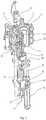
- FIG Fig. 1 The basic structure of a device for reshaping preforms 1 in container 2 is shown in FIG Fig. 1 and in Fig. 2 shown.
- the arrangement can take place as shown or rotated by 180 ° in a vertical plane.
- the device for shaping the container 2 essentially consists of a blowing station 3 which is provided with a blow mold 4 into which a preform 1 can be inserted.
- the preform 1 can be an injection-molded part made of polyethylene terephthalate.
- the blow mold 4 consists of mold halves 5, 6 and a base part 7 which can be positioned by a lifting device 8.
- the preform 1 can be fixed by a holding element 9 in the area of the blowing station 3.
- This holding element 9 can, for example, be designed according to the invention or as known in the prior art. It is possible, for example, to insert the preform 1 directly into the blow mold 4 using tongs or other handling means.
- a connecting piston 10 is arranged below the blow mold 4, which piston 10 supplies compressed air to the preform 1 and at the same time performs a seal.
- piston 10 supplies compressed air to the preform 1 and at the same time performs a seal.
- it is basically also conceivable to use fixed compressed air supply lines.
- the preform 1 is stretched with the aid of a stretching rod 11 which is positioned by a cylinder 12.
- the stretching rod 11 is mechanically positioned by means of curved segments which are acted upon by pick-up rollers. The use of curve segments is particularly useful when a plurality of blowing stations 3 are arranged on a rotating blowing wheel 25.
- the stretching system is designed in such a way that a tandem arrangement of two cylinders 12 is provided.
- the stretching rod 11 is first moved by a primary cylinder 13 into the area of a base 14 of the preform 1.
- the primary cylinder 13 with the stretching rod extended, together with a carriage 15 carrying the primary cylinder 13, is positioned by a secondary cylinder 16 or via a cam control.
- the idea is to use the secondary cylinder 16 in a cam-controlled manner in such a way that a guide roller 17, which during the stretching process is carried out on a Slides along the curved path, a current stretching position is specified.
- the guide roller 17 is pressed against the guide track by the secondary cylinder 16.
- the carriage 15 slides along two guide elements 18.
- the carriers 19, 20 are locked relative to one another with the aid of a locking device 40 Fig. 2 the use of separate threaded inserts 22 in the area of the blow mold 4 is provided.
- Fig. 2 shows, in addition to the blown container 2, also drawn in dashed lines, the preform 1 and, schematically, a developing container bubble 23.
- Fig. 3 shows the basic structure of a blow molding machine which is provided with a heating section 24 and a rotating blow wheel 25.
- the preforms 1 are transported by transfer wheels 27, 28, 29 into the area of the heating section 24.
- Radiant heaters 30 as heating devices and fans 31 are arranged along the heating section 24 in order to control the temperature of the preforms 1.
- they are transferred by a transfer wheel 35 to the blow wheel 25, in the area of which the blow stations 3 are arranged.
- the fully blown containers 2 are fed to an output section 32 by further transfer wheels 37, 28, 38.
- the transfer wheel 37 is designed as a removal wheel and the transfer wheel 38 as an output wheel.
- thermoplastic material polyethylene terephthalate
- PEN polyethylene naphthalate
- PP polypropylene
- the preform 1 is expanded during the orientation process by supplying compressed air.
- the compressed air supply is divided into a pre-blowing phase, in which gas, for example compressed air, is supplied at a low pressure level, and is divided into a subsequent main blowing phase, in which gas is supplied at a higher pressure level.
- gas for example compressed air
- main blowing phase in which gas is supplied at a higher pressure level.
- compressed air is typically used with a pressure in the range from 10 bar to 25 bar and during the main blowing phase, compressed air is supplied with a pressure in the range from 25 bar to 40 bar.
- the heating path 24 is part of the transport path of the preforms 1.
- the preforms 1 are transported in the heating device H by means of a multiplicity of revolving transport elements 33 which are strung together like a chain and are guided along deflection wheels 34, 36.
- the revolving transport elements 33 therefore move along a chain path 55, which also forms the transport path for the preforms, since the preforms 1 are guided along the chain path 55.
- it is intended to create a substantially rectangular basic contour through the chain-like arrangement of the transport elements 33.
- a single, relatively large-dimensioned deflecting wheel 34 is used in the area of the extension of the heating path 24 facing the transfer wheel 27 and two comparatively smaller-dimensioned deflecting wheels 36 are used in the area of adjacent deflections.
- any other guides are also conceivable.
- the arrangement shown proves to be particularly expedient, since three deflecting wheels 34, 36 are positioned in the area of the corresponding extension of the transport path 55, namely the smaller deflecting wheels 36 in the area the transition to the linear courses of the transport path 55 and the larger deflection wheel 34 in the immediate transfer area to the transfer wheel 27 and to the blower wheel 25.
- chain-like transport elements 33 it is also possible, for example, to use a rotating heating wheel.
- the preforms 1 and the containers 2 can be transported through the blow molding machine B in different ways.
- the preforms are carried by transport mandrels at least along the essential part of their transport path.
- Different variants are also conceivable with regard to the spatial orientation of the preforms.
- the preform is fed in the area of the preform input 26 with its mouth oriented vertically upwards, then rotated, conveyed along the heating section 24 and the blow wheel 25 with its mouth oriented vertically downwards and before reaching the output section 32 turned again.
- the preform 2 is heated in the area of the heating section 24 with its mouth oriented downwards in a vertical direction, but is rotated again by 180 ° before reaching the blow wheel 25.
- the preform runs through the entire area of the blow molding machine B with its mouth oriented vertically upwards without performing turning processes.
- FIGS 4 and 5 show a perspective view of part of a conveyor chain F according to the invention.
- the transport means 33 are pivotably connected to one another.
- the shown part of a conveyor chain F consisting of several chain links 33 is guided on guide rails 51 and 52 in a meandering folded position.
- the chain links 33 are laterally supported by means of support rollers 42 on a side guide 49.
- the lateral guide 49 can be used to compensate for transverse forces or torques that arise, for example, from the suspension of the chain links 33 in the perpendicular direction to the side of the center of gravity.
- the chain links 33 are suspended from a rail-like guide means 52.
- the guide rollers 43 arranged on the chain links 33 have annular grooves which interact with webs of the guide rail 52 that are designed to be complementary thereto. This enables a conveyor chain F formed from chain links 33 to be suspended along a guide rail 52.
- At least some chain links 33 have stacks of guide rollers which have a plurality of guide rollers 43 arranged one above the other, the individual guide rollers 43 in the stack assembly being rotatable in different directions of rotation.
- the guide rollers 43 in the stack assembly can each be supported laterally in different directions on the guide rail 52, so that the chain links 33 are prevented from deviating at right angles to the transport direction.
- Torques transverse to the transport direction of the conveyor chain F which arise, for example, in the case of a guide and support rail 52 offset laterally to the perpendicular direction of the center of gravity of the chain links 33, can also be advantageously compensated.
- lateral forces or torques can be compensated with the lateral guide 49.
- further guide rollers 50 can be provided, which are guided on a further guide means 51 designed as a guide rail.
- the guide roller 50 serves to guide the respective chain link 33 laterally during the transport of the preforms 1 along the transport path T of the heating device H (cf. Fig. 3 ).
- the conveyor chain can be guided along the transport path on the one hand and can also be moved from a folded position to a stretched position or from a stretched position to a folded position while running along the transport route.
- the guide rollers 50 and 43 can be moved towards one another forcibly by reducing the distance between the rails 51 and 52. In this case, torques are transmitted to the chain links 33, which cause a rotation about the swivel joints connecting the chain links 33.
- the conveyor chain F is folded or unfolded.
- the radiation diaphragms 41 movably mounted on the chain links 33 in the holding area of the preforms 1 can be controlled.
- diaphragm levers 44 run in a guide groove in the guide rail 53.
- the radiation diaphragm 41 positively follows the twisting movement. The radiation diaphragms can thus be rotated relative to the chain links 33.
- the lever arms of the panel lifts 44 are guided in longitudinal grooves of the panel guide 53. If the chain links 33, as in the Figures 6 and 7 shown, are rotated with respect to one another, for example by a suitable curved guide of the guide rails 51 and / or 52, the radiation diaphragms 41 are rotated relative to the chain links 33 by a suitable course of the diaphragm guide 53. As a result, the radiation diaphragm 41, which closes the gaps between two preforms 1 transported one behind the other in a row, can be removed from the preforms 1 collision-free when the conveyor chain F passes from a folded position to a stretched position.
- FIGS 6 and 7 show the partial areas of the conveyor chain 11 from Figures 4 and 5 from a different perspective from diagonally above.
- the guide rails 51 and 52 and the diaphragm guide 53 are not shown.
- Subregions of the conveyor chain F shown during the transition from a folded position to a stretched position are shown.
- the preforms 1 held on the handling means 39 of the chain links 33 are guided in two rows along the transport path.
- the stretched position the preforms 1 are guided in one row along the transport path.
- the distance between two preforms guided one behind the other in a row is significantly smaller in two-row transport in the folded position than in single-row transport of the preforms in the stretched position.
- the preforms are preferably transported in two rows in the region of a heating path 24 in a heating direction H.
- the distances between the preforms in two-row transport are kept as small as possible, which offers various advantages.
- the small distances mean, for example, that as little radiation energy as possible, which acts on the body area of the preform 1 below its support ring 47 in the area of radiant heaters 30 of the heating path 24, is lost in the vertical direction upwards.
- radiation diaphragms 41 can be arranged on the chain links 33, which largely close the gaps between two consecutive preforms 1 of each individual row when the preforms 1 are transported in two rows.
- the radiation diaphragms 41 are movably arranged, in particular rotatably mounted on at least some chain links 33.
- the radiation diaphragms 41 can be moved by means of diaphragm guide means 53 designed as levers, so that the radiation diaphragms 41 can be moved into a release position in which they guide the spaces between two in a row one behind the other Preforms 1 released.
- the radiation diaphragms 41 can be moved into a blocking position in which they largely block the spaces between two preforms 1 transported in a row, as explained.
- the radiation diaphragms 41 can have a plate-like design and each have two concave recesses 45 machined into the material of the radiation diaphragm 41 on opposite edges.
- the radiation diaphragms 41 are shown in the blocking position in which they block the spaces between preforms 1 guided one behind the other.
- Two radiation diaphragms 41 are brought together in such a way that the recesses 45 of these two combined radiation diaphragms 41 are opposite one another and together form an approximately circular cutout which provides a passage for the body of a preform 1.
- the recesses 45 of the radiation diaphragms 41 encompass the preform 1, preferably below its support ring 47, in each case in an angular range.
- the recesses 45 are preferably designed in such a way that the radiation diaphragms 41, in their blocking position, see the support ring 47 in the longitudinal direction of the preform 1 overlap. This closes the spaces between the preforms 1 particularly well. In addition, in particular, unwanted heating of the support rings 47 during transport through the heating section 24 can be prevented.
- the preforms 1 are for transport along the transport path T of the heating device H (cf. Figure 3 ) held on handling means 39 of the chain links 33.
- the handling means 39 have holding devices 48 designed as holding mandrels which - as explained at the beginning - can be designed for the passive or active holding of the preforms.
- FIGS. 8 and 9 show possible routes during the transport of the preforms 1 along a transport path T of a heating device H.
- the direction of transport is indicated by arrows R.
- a single-row transport of the preforms 1 is provided in the areas 54 and a two-row transport of the preforms 1 is provided in the areas 55.
- two separate areas 55 can be provided for two-tier transport.
- the areas 55 are off according to the example Figure 8 separated by two areas 54 in which a single-row transport of the preforms 1 is provided.
- FIG. 8 In contrast, for example, from Figure 8 is after Figure 9 In each case one area 55 is provided for two-row transport and a single area 54 for single-row transport of the preforms 1.
- the schematic representations of the Figures 8 and 9 show a typical course of a transport path T of a conveyor chain F through a heating device H (cf. Figure 3 ).
- the rectilinearly guided areas of the transport path T can be the heating paths 24, which are formed by individual heating devices 30.
- These heating devices 30 can have infrared radiators, for example, which are used to control the temperature of the preforms 1 as they are transported through the heating section 24.
- the preforms 1 are guided in two rows, in particular in the area of the straight guidance of the transport path T between opposing curved areas.
- the preforms 1 in one Curved area between two rectilinear areas of the transport path T are transported in two rows.
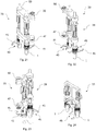
- FIGS 10 to 15 show a further embodiment of the conveyor chain F according to the invention schematically in different representations.
- elements that are also used for the first exemplary embodiment of Figures 4 to 7 are omitted in the drawings.
- rail-shaped guide means 51, 52 for controlling the conveyor chain F can also be provided in this exemplary embodiment.
- FIG. 10 to 14 show part of a conveyor chain F according to the invention during the transition from a folded position 57 to a stretched position 58. It can be clearly seen that the preforms 1 carried on the handling means 39 of the chain links 33 are transported in a single row in the direction of transport in the area of the stretched position 58 and in the area of the Folded position 57 can be transported in two rows in two rows running parallel to one another with respect to the transport direction. The small distance between two consecutive preforms 1 in a row in the area of the folded position 57 compared to the, on the other hand, greater distance between two consecutive preforms 1 in the area of the stretched position 58 can also be clearly seen.
- FIGS Figures 4 to 7 Another difference from the embodiment according to FIGS Figures 4 to 7 is the rigid or immovable arrangement of radiation diaphragms 41 on the chain links 33.
- the radiation diaphragms 41 as in the example of the committee, point to the Figures 4 to 7 in each case two recesses 45 which are incorporated into the material on opposite sides of the plate-shaped elements 41.
- two radiation diaphragms 41 are provided on each of the chain links 33.
- the blocking position of the radiation diaphragms 41 is assumed solely by the folding movement of the conveyor chain F.
- the radiation diaphragms 41 are in the blocking position in which they block the space between two consecutive preforms 1. In the In the extended position 58, the radiation diaphragms 41 are in a release position in which the preforms can be removed from the engagement of the radiation diaphragms 41 without collision.
- two opposing radiation diaphragms 41 with their recesses 45 facing one another each encompass a preform 1. Because of their rigid arrangement on the chain links 33, the relative position of the radiation diaphragms 41 of a chain link 33 with respect to the preforms 1 carried on the same chain link 33 is reduced during the transition from a folded position 57 in an extended position 58 is not changed.
- the chain links 33 each carry two preforms 1, with a first preform 1 being guided out of the engagement area of a radiation diaphragm 41 of the subsequent chain link 33 in the stretching direction, that is, forced out of the encompassing the subsequent radiation diaphragm 41 when transitioning from a folded position 57 to a stretched position 58.
- the second preform 1 carried on this chain link 33 is released during the transition to the stretched position 58 in that the associated radiation diaphragm 41 of the chain link 33 leading in the stretching direction is moved away from this preform 1.
- This principle is good in Figure 12 recognizable.
- the recesses 45 are approximately tong-like, with two lateral cheek elements being shaped as wrap-around areas for gripping around the preforms 1 in areas.
- the releasing recess 45 is designed asymmetrically to the opposite recess 45 of the same radiation diaphragm 41.
- the released recess 45 is worked obliquely into the plate-shaped body of the radiation diaphragm 41, such that the released recess 45 forms a first protruding wrap-around area 61 and a second, opposite, recessed wrap-around area 62.
- the recessed wrap-around area 62 in the folded position 57 of the conveyor chain F in any case in a straight-line transport section of the transport path T directly to one opposite encompassing area of a recess 45 of a subsequent radiation diaphragm 41 is adjacent.
- the hook-shaped protruding wrap-around area 61 can be designed in such a way that it overlaps with a wrap-around area of an opposing recess 45 of a subsequent radiation diaphragm 41 at least in a straight transport section of the transport path T.
- the oblique shape of the released recess enables a collision-free introduction or removal of a preform 1 into or out of the released recess 45 during the transition from an extended position 58 to a folded position 57 of the transport chain T or during the transition from a folded position 57 to an extended position 58
- Material recesses on the upper side or the underside of the radiation diaphragms 41 in the area surrounding the released or stationary recess 45 can also be designed in such a way that there is sufficient room to move in order to enable the two-row transport of the preforms even in the curved area of a transport path T.
- the overlap between the protruding wrap-around area 61 with the stationary radiation diaphragm 41 can vary in the curve guidance.
- Figure 14 shows the part of the conveyor chain F from the Figures 10 to 13 in a side view.
- Figure 15 shows a section through a chain link 33 along the section line 15-15 from FIG Figure 14.
- Figure 14 illustrates the high transport density of the preforms 1 in the area of the folded position compared to the significantly lower transport density of the preforms 1 in the area of the stretched position.
- the guide pins 59 which are arranged at the upper end of the handling means 39 in this exemplary embodiment, can serve to guide the chain links 33 during transport through the heating device H.
- the guide pins 59 can also be used to control the handling means 39.
- the guide pins 59 are part of the holding mandrels carrying the preforms. It is conceivable that the holding of the preforms 1 on the holding mandrel is released by pressure on a guide pin 59 - for example by means of a control cam (not shown) arranged stationary to the conveyor chain.
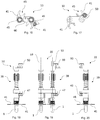
- the Figures 16 to 24 show a chain link 33 from the conveyor chain part of FIG Figures 10 to 14 in different views. Two are clearly recognizable with one each Handling means 39 equipped with a transport mandrel are arranged on the chain link 33. Preforms 1 are held on the transport mandrels at the bottom in the perpendicular direction.
- the radiation diaphragms 41 are stationary, that is to say immovable, on the chain links 33.
- the radiation diaphragms 41 are mounted on a support element 60.
- the radiation diaphragms 41 can be formed in one piece or integrally with the support element 60.
- the radiation diaphragms 41 can each also be detachably attached to the support element 60.
- the support element 60 is preferably detachably fastened to the support frame of the chain link 33, for example with a screw fastening.
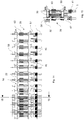
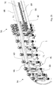
- a transport device designed as a conveyor chain is shown at the transition from the two-row transport area 55 to the single-row transport area 54.
- a conveyor device 69 designed as a drag chain is shown, which drives the transport means 33 designed as chain links in the area of the two-row guide.
- the drag chain has drivers 70 which are designed as chain links and which engage in driver elements 71 fastened to the chain links 33.
- the chain links 33 have guide rollers 50 in their shoulder area, which run in guide rails 68. Every second chain link carries a lateral support roller 42, which run at least in the two-row transport area 55 on a guide rail 66 in order to support the conveyor chain in the vertical direction against the force of gravity.
- FIG. 13 is a cross-sectional view of the conveyor chain of FIGS Figures 25 and 26th shown with a view in the vertical direction from below. It can be clearly seen that every second chain link 33 carries a driver element 71. It can also be clearly seen that the Carrier elements 71 in the two-row transport area 55 in the folded position 57 of the conveyor chain are each in engagement with carriers 70 of the conveyor device 69 designed as a drag chain. When the drag chain 69 is driven in the transport direction R, the chain links 33 are advanced. In the transition area between the folded position 57 and the stretched position 58, the distance between the guide rails 68 is reduced.
Landscapes
- Engineering & Computer Science (AREA)
- Manufacturing & Machinery (AREA)
- Mechanical Engineering (AREA)
- Physics & Mathematics (AREA)
- Thermal Sciences (AREA)
- Blow-Moulding Or Thermoforming Of Plastics Or The Like (AREA)
Description
Die Erfindung betrifft eine Heizvorrichtung zur thermischen Konditionierung von für die Blasformung vorgesehenen Vorformlingen nach dem Oberbegriff des Anspruchs 1, eine Blasmaschine nach dem Oberbegriff des Anspruchs 12 und ein Verfahren zum Transport von aus thermoplastischem Material bestehenden Vorformlingen nach dem Oberbegriff des Anspruchs 13The invention relates to a heating device for the thermal conditioning of preforms intended for blow molding according to the preamble of
Bei einer Behälterformung durch Blasdruckeinwirkung werden Vorformlinge aus einem thermoplastischen Material, beispielsweise Vorformlinge aus PET (Polyethylenterephthalat), innerhalb einer Blasmaschine, also innerhalb einer Vorrichtung zur blasumformenden Herstellung von Fertigbehältern aus Vorformlingen, unterschiedlichen Bearbeitungsstationen zugeführt. Typischerweise weist eine derartige Blasformungsmaschine bzw. Blasmaschine eine Aufheizvorrichtung sowie eine Blaseinrichtung auf, in deren Bereich der zuvor in der Aufheizvorrichtung temperierte Vorformling durch biaxiale Orientierung zu einem Behälter expandiert wird. Die Expansion erfolgt z.B. mit Hilfe von Druckluft, die in den zu expandierenden Vorformling eingeleitet wird. Der verfahrenstechnische Ablauf bei einer derartigen Expansion des Vorformlings wird zum Beispiel in der Druckschrift
Die Einleitung des unter Druck stehenden Gases umfasst auch die Druckgaseinleitung in die sich entwickelnde Behälterblase sowie die Druckgaseinleitung in den Vorformling zu Beginn des Blasumformvorganges bzw. Blasvorganges. Es sind auch andere Fluide zur Blasformung verwendbar, insbesondere auch die Verwendung des in den Behälter abzufüllenden Füllgutes. Die nachfolgende allgemeine Beschreibung erfolgt gleichwohl am Beispiel einer mit Druckgas arbeitenden Blasmaschine, ohne dass sich die Erfindung auf solche Blasmaschinen beschränkt.The introduction of the pressurized gas also includes the introduction of pressurized gas into the developing container bubble and the introduction of pressurized gas into the preform at the beginning of the blow molding process or blowing process. Other fluids can also be used for blow molding, in particular also the use of the filling material to be filled into the container. The following general description is nevertheless based on the example of a blow molding machine operating with compressed gas, without the invention being restricted to such blow molding machines.
Der grundsätzliche Aufbau einer Blasstation zur Behälterformung wird zum Beispiel in der Druckschrift
Innerhalb der Vorrichtung zur Blasformung können die Vorformlinge sowie die geblasenen Behälter mit Hilfe unterschiedlicher Transport- und Handhabungseinrichtungen transportiert werden. Bekannt ist z.B. die Verwendung von Transportdornen, an denen die Vorformlinge zum Transport gehaltert sind. Die Vorformlinge können aber auch mit anderen Trageinrichtungen gehandhabt und transportiert werden. Die Verwendung von Greifzangen zur Handhabung und zum Transport von Vorformlingen und die Verwendung von Klemmdornen, die zur Halterung in einen Mündungsbereich des Vorformlings einführbar sind, gehören ebenfalls zu den verfügbaren Konstruktionen.Within the blow molding device, the preforms and the blown containers can be transported with the aid of various transport and handling devices. It is known, for example, to use transport mandrels on which the preforms are held for transport. However, the preforms can also be handled and transported with other carrying devices. The use of gripping tongs for handling and transporting preforms and the use of clamping mandrels which can be inserted into an opening area of the preform for holding purposes also belong to the constructions available.
Ein Transport und eine Handhabung von Behältern und Vorformlingen unter Verwendung von Übergaberädern wird beispielsweise in der
Die bereits erläuterte Handhabung der Vorformlinge erfolgt zum einen bei den sogenannten Zweistufenverfahren, bei denen die Vorformlinge zunächst in einem Spritzgussverfahren hergestellt, anschließend zwischengelagert und erst später hinsichtlich ihrer Temperatur konditioniert und zu einem Behälter aufgeblasen werden. Zum anderen erfolgt eine Anwendung bei den sogenannten Einstufenverfahren, bei denen die Vorformlinge unmittelbar nach ihrer spritzgusstechnischen Herstellung und einer ausreichenden Verfestigung geeignet temperiert und anschließend aufgeblasen werden.The handling of the preforms already explained takes place on the one hand in the so-called two-stage process, in which the preforms are first produced in an injection molding process, then temporarily stored and only later conditioned with regard to their temperature and inflated to form a container. On the other hand, there is an application in the so-called one-step process, in which the preforms are suitably tempered immediately after their injection molding production and sufficient solidification and then blown up.
Im Hinblick auf die verwendeten Blasstationen sind unterschiedliche Ausführungsformen bekannt. Bei Blasstationen, die auf rotierenden Transporträdern angeordnet sind, nämlich auf einem sogenannten Blasrad, ist eine buchartige Aufklappbarkeit der Formträger häufig anzutreffen. Es ist aber auch möglich, relativ zueinander verschiebliche oder andersartig geführte Formträger einzusetzen. Bei ortsfesten Blasstationen, die insbesondere dafür geeignet sind, mehrere Kavitäten zur Behälterformung aufzunehmen, werden typischerweise parallel zueinander angeordnete Platten als Formträger verwendet.With regard to the blowing stations used, different embodiments are known. In the case of blowing stations that are arranged on rotating transport wheels, namely on a so-called blowing wheel, the mold carriers can often be opened in a book-like manner. However, it is also possible to use mold carriers which can be displaced relative to one another or are guided in a different manner. In the case of stationary blowing stations, which are especially designed for this are suitable to accommodate several cavities for container molding, plates arranged parallel to one another are typically used as mold carriers.
Vor einer Durchführung der Beheizung werden die Vorformlinge typischerweise auf Transportdorne aufgesteckt, die den Vorformling entweder durch die gesamte Blasmaschine transportieren oder die lediglich im Bereich der Aufheizvorrichtung umlaufen. Bei einer stehenden Beheizung der Vorformlinge derart, dass die Mündungen der Vorformlinge in lotrechter Richtung nach unten orientiert sind, werden die Vorformlinge üblicherweise auf ein hülsenförmiges Halterungselement des Transportdornes aufgesteckt. Bei einer hängenden Beheizung der Vorformlinge, bei der diese mit ihren Mündungen in lotrechter Richtung nach oben orientiert sind, werden in der Regel Spreizdorne in die Mündungen der Vorformlinge eingeführt, die die Vorformlinge festklemmen. Aus dem Stand der Technik sind sowohl aktive, steuerbare als auch passive Klemmelemente bekannt. Passive Klemmelemente bewirken z.B. eine Klemmung aufgrund einer einwirkenden Federkraft, gegen die die Vorformlinge auf die Transportdorne aufgesteckt werden oder gegen die die Vorformlinge vom Transportdorn abgenommen werden, während bei den aktiven Transportdornen eine Betätigung erfolgen muss, z.B. aktorisch oder z.B. durch eine externe Kurvensteuerung, die den Klemmmechanismus auslöst bzw. den Klemmeingriff wieder aufhebt.Before the heating is carried out, the preforms are typically placed on transport mandrels which either transport the preform through the entire blow molding machine or which only circulate in the area of the heating device. When the preforms are heated upright in such a way that the mouths of the preforms are oriented vertically downwards, the preforms are usually placed on a sleeve-shaped holding element of the transport mandrel. With a hanging heating of the preforms, in which these are oriented with their mouths in a vertical direction upwards, expanding mandrels are usually inserted into the mouths of the preforms, which clamp the preforms. Both active, controllable and passive clamping elements are known from the prior art. Passive clamping elements cause, for example, a clamping due to an acting spring force, against which the preforms are attached to the transport mandrels or against which the preforms are removed from the transport mandrel, while the active transport mandrels have to be actuated, e.g. actuators or e.g. by an external cam control, which triggers the clamping mechanism or releases the clamping engagement again.
Zur Verkürzung der erforderlichen Aufheizzeit ist es bekannt, im Bereich der Heizstrecke NIR-Strahler zu verwenden, deren Heizstrahlung in einem nahen Infrarotbereich emittiert wird, typischerweise mit Wellenlängen zwischen 0,4 und 1 Mikrometer. Die Aufheizung der Vorformlinge erfolgt dabei primär durch Strahlungsabsorption beim Durchgang der NIR-Strahlung durch das Vorformlingsmaterial. Zur Optimierung der Energieausbeute werden derartige Heizstrecken mit einer Vielzahl von Reflektionsflächen ausgestattet, um eine Absorption der Wärmestrahlung durch Bauteile der Heizstrecke möglichst zu vermeiden oder zumindest stark zu reduzieren, und um die NIR-Strahlung erneut zum Heizen auf den Vorformling zu reflektieren.To shorten the required heating time, it is known to use NIR radiators in the area of the heating path, the heating radiation of which is emitted in a near infrared range, typically with wavelengths between 0.4 and 1 micrometer. The preforms are heated primarily by absorption of radiation when the NIR radiation passes through the preform material. To optimize the energy yield, such heating sections are equipped with a large number of reflective surfaces in order to avoid or at least greatly reduce absorption of the thermal radiation by components of the heating section, and to reflect the NIR radiation again onto the preform for heating.
Typischerweise werden die Heizstrecken zumindest bereichsweise tunnelartig ausgebildet. Die Heizstrecken sind dazu zum Beispiel auf der einen Seite vom Gehäuse mit einer Halterung für die Heizelemente und auf der gegenüberliegenden Seite von einem diesem Gehäuse gegenüberliegenden Reflektor begrenzt; auch als Gegenreflektor bekannt. In vertikaler Richtung kann eine Begrenzung durch einen Boden und/oder einen Deckel erfolgen, je nachdem, ob die Vorformlinge mit ihren Mündungen in lotrechter Richtung nach oben oder nach unten orientiert durch die Heizstrecke hindurch transportiert werden. Auch diese vertikalen Begrenzungen können als Reflektoren ausgebildet werden. Es ist zudem üblich, den Mündungsbereich des Vorformlings zum Beispiel mittels mitlaufender Reflektoren, auch als Mündungsreflektoren bezeichnet, gegen erwärmende Strahlung zu schützen, da dieser Bereich bereits fertig ausgeprägt hergestellt ist und bei der Blasformung keine weitere Verformung erfahren soll.The heating sections are typically designed in the manner of a tunnel, at least in some areas. For this purpose, the heating sections are limited, for example, on one side by the housing with a holder for the heating elements and on the opposite side by a reflector opposite this housing; also known as a counter reflector. In the vertical direction, a boundary by a floor and / or a Lids are made depending on whether the preforms are transported through the heating section with their mouths oriented vertically upwards or downwards. These vertical boundaries can also be designed as reflectors. It is also customary to protect the mouth area of the preform, for example by means of reflectors running along, also referred to as mouth reflectors, against heating radiation, since this area is already produced in a fully embossed manner and should not undergo any further deformation during blow molding.
Der Aufheizvorgang und die Ausbildung eines definierten Temperaturprofils ist ein wichtiger Prozessschritt zur Vorbereitung der Vorformlinge für die Blasumformung in Behälter. Anhand des beim Heizprozess in das Wandmaterial des Vorformlings eingeprägten Temperaturprofils bestimmen sich wesentliche Prozessparameter für die in der Blasstation durchgeführte biaxiale Ausdehnung des Vorformlings. Beispielsweise werden durch das Temperaturprofil die maximale Geschwindigkeit einer in den Vorformling eingeführten Reckstange und die maximale Expansionsgeschwindigkeit der Behälterblase bei der Druckbeaufschlagung des Vorformlings bestimmt. Höhere Geschwindigkeiten führen zu größeren Durchsatzraten und damit zur Effizienzsteigerung der Blasmaschine.The heating process and the formation of a defined temperature profile is an important process step in preparing the preforms for blow molding in containers. The temperature profile impressed on the wall material of the preform during the heating process is used to determine the essential process parameters for the biaxial expansion of the preform carried out in the blowing station. For example, the temperature profile determines the maximum speed of a stretching rod introduced into the preform and the maximum expansion speed of the container bubble when the preform is pressurized. Higher speeds lead to higher throughput rates and thus to an increase in the efficiency of the blow molding machine.
Ein hoher Durchsatz von Vorformlingen durch die Blasmaschine benötigt einen erhöhten Durchsatz von Vorformlingen beim Transport durch die vorgelagerte Aufheizvorrichtung. Damit steigt der für die Aufheizung der Vorformlinge benötigte Energiebedarf. Zum Aufheizen der Vorformlinge wird üblicherweise elektrische Energie in thermische Energie umgewandelt, die dann üblicherweise über Strahlung in die Vorformlinge eingetragen wird. Bei steigenden Durchsatzraten durch die Blasmaschine und durch die Aufheizvorrichtung steigt nicht nur die für den Aufheizprozess benötigte Energiemenge sondern auch die durch einzelne Prozessschritte bedingten Energieverluste. Verluste thermischer Energie entstehen beispielsweise durch Absorption von Wärmestrahlung an Bauteilen der Heizvorrichtung oder durch Strahlungsverluste an in der Heizvorrichtung technisch bedingten Öffnungen zur Umgebung. Aus wirtschaftlichen Gründen und zur Schonung vorhandener Ressourcen besteht die anhaltende Bestrebung, den Energieverluste möglichst gering zu halten.A high throughput of preforms through the blow molding machine requires an increased throughput of preforms during transport through the upstream heating device. This increases the energy required to heat the preforms. To heat the preforms, electrical energy is usually converted into thermal energy, which is then usually introduced into the preforms via radiation. With increasing throughput rates through the blow molding machine and through the heating device, not only does the amount of energy required for the heating process increase, but also the energy losses caused by individual process steps. Losses of thermal energy arise, for example, through absorption of thermal radiation on components of the heating device or through radiation losses at openings to the environment that are technically required in the heating device. For economic reasons and to conserve existing resources, there is an ongoing effort to keep energy losses as low as possible.
Nennenswerte Wärmeverluste im Bereich der Aufheizvorrichtung entstehen insbesondere durch das Entweichen von Wärmestrahlung im Bereich der Heizstrecke durch Lücken zwischen den an Transportdornen getragenen Vorformlingen. Zur Lösung dieses Problems werden typischerweise Mündungsreflektoren in Form von Lochblenden verwenden, mit denen die Lücken teilweise geschlossen werden. Üblicherweise befindet sich der Mündungsbereich der Vorformlinge auf der Schattenseite der Lochblende und der Vorformlingskörper auf der Strahlungsseite der Lochblende. Der Vorformlingskörper wird beim Transport durch die Heizvorrichtung aufgeheizt und der Mündungsbereich wird durch die Lochblende vor Überhitzung geschützt. Die Vorformlinge können durch die Bohrung der Lochblenden hindurch aufgenommen und während des Transports entlang der Heizstrecke in einer in die Lochblende eingetauchten Position gehalten werden. Derartige Lösungen sind zum Beispiel aus
Beim Transport der Vorformlinge durch eine Heizvorrichtung einer Blasmaschine ist besonderes Augenmerk darauf gelegt, das erforderliche Temperaturprofil bei einem hohen Wirkungsgrad der Heizelemente mit möglichst hohen Durchsatzraten zu erreichen. Zentrale Rolle spielt dabei die Ausgestaltung und die Funktionsweise des Transportsystems, das für die Hantierung und Halterung der Vorformlinge bei ihrer Führung entlang eines Transportweges durch die Heizvorrichtung verwendet wird. Aufgabe der vorliegenden Erfindung ist die Bereitstellung einer Heizvorrichtung der eingangs genannten Art mit einem verbesserten Transportsystem das bei hohen Durchsatzraten ein energieeffizientes Aufheizen der Vorformlinge unterstützt. Weitere Aufgabe ist die Bereitstellung eines Verfahrens zum Transport von Vorformlingen entlang eines Transportweges einer solchen Heizvorrichtung.When the preforms are transported through a heating device of a blow molding machine, particular attention is paid to achieving the required temperature profile with a high degree of efficiency of the heating elements with the highest possible throughput rates. The design and functioning of the transport system that is used for handling and holding the preforms when they are guided along a transport path through the heating device plays a central role. The object of the present invention is to provide a heating device of the type mentioned at the beginning with an improved transport system which supports energy-efficient heating of the preforms at high throughput rates. A further object is to provide a method for transporting preforms along a transport path of such a heating device.
Diese Aufgabe wird gelöst durch eine Heizvorrichtung mit den Merkmalen des Anspruchs 1, eine Blasmaschine mit den Merkmalen des Anspruchs 12 und ein Verfahren zum Transport von Vorformlingen mit den Merkmalen des Anspruchs 13 Vorteilhafte Ausgestaltungen sind in den Unteransprüchen angegeben.This object is achieved by a heating device with the features of
Erfindungsgemäß ist eine Heizvorrichtung mit mindestens einer Heizstrecke zur thermischen Konditionierung von aus thermoplastischem Material bestehenden Vorformlingen auf ein für eine Blasumformung geeignetes Temperaturprofil, wobei die Heizvorrichtung eine Transporteinrichtung zum Transport der Vorformlinge entlang eines Transportweges der Heizvorrichtung aufweist, und wobei die Transporteinrichtung Handhabungsmittel zur Halterung und Hantierung jeweils eines einzelnen Vorformlings aufweist, dadurch gekennzeichnet, dass die Transporteinrichtung derart ausgebildet und eingerichtet ist, dass die Vorformlinge in mindestens einem ersten Abschnitt des Transportweges in einer einzigen Reihe geführt sind und in mindestens einem zweiten Abschnitt des Transportweges in zwei benachbarten Reihen geführt sind.According to the invention, a heating device with at least one heating section for the thermal conditioning of preforms made of thermoplastic material to a temperature profile suitable for blow molding, wherein the heating device has a transport device for transporting the preforms along a transport path of the heating device, and wherein the transport device Has handling means for holding and handling an individual preform, characterized in that the transport device is designed and set up such that the preforms are guided in at least a first section of the transport path in a single row and in at least a second section of the transport path in two adjacent rows Rows are led.
Bei einem mehrreihigen Transport der Vorformlinge ist vorteilhaft, dass der zur Verfügung stehende Bauraum der Heizvorrichtung optimal genutzt werden kann. Im Vergleich zur herkömmlichen einreihigen Führung der Vorformlinge kann beim mehrreihigen Transport der radial zur Umlaufbahn der Transportstrecke innenliegende Raumbereich zur Führung einer weiteren Reihe von Vorformlingen genutzt werden, was einen kompakten Aufbau der Heizvorrichtung und eine geringe Längsausdehnung der Heizstrecken gestattet. Als Transportweg wird insbesondere der Weg verstanden, den ein Vorformling beim Durchlaufen der Heizvorrichtung durchläuft.In the case of multi-row transport of the preforms, it is advantageous that the space available for the heating device can be optimally used. In comparison to the conventional single-row guidance of the preforms, the space area lying radially inside the orbit of the transport path can be used to guide a further row of preforms during multi-row transport, which allows a compact construction of the heating device and a small longitudinal extension of the heating paths. The transport path is understood to mean, in particular, the path that a preform traverses when passing through the heating device.
Eine Herausforderung ist beim mehrreihigen Transport, dass zur Hantierung von in mehreren Reihen geführten Vorformlingen insbesondere im Zuführ- oder Abgabebereich der Heizvorrichtung, in denen die Vorformlinge in die Transporteinrichtung aufgenommen bzw. daraus abgegeben werden, spezielle Aufnahme- oder Abgabeeinrichtungen nötig sind, die sowohl die auf außenliegenden als auch die auf innenliegenden Bahnen geführten Vorformlinge erreichen. Das erhöht die Komplexität und die Fehleranfälligkeit der eingesetzten Transport- und Handhabungseinrichtungen. Ein wichtiger Aspekt der Erfindung ist daher, dass die Vorformlinge während des Transports durch die Heizeinrichtung von einer mehrreihigen Führung in eine einreihige Führung überführt werden können.One challenge in multi-row transport is that, in order to handle preforms guided in several rows, in particular in the feed or discharge area of the heating device, in which the preforms are received in or discharged from the transport device, special receiving or dispensing devices are required that both Reach preforms on the outside as well as on the inside tracks. This increases the complexity and the susceptibility to errors of the transport and handling equipment used. An important aspect of the invention is therefore that the preforms can be transferred from a multi-row guide to a single-row guide while they are being transported through the heating device.
Im Bereich der einreihigen Führung der Vorformlinge, also in einem ersten Abschnitt des Transportweges, können zur Übergabe von Vorformlingen in die Transporteinrichtung oder zu ihrer Entnahme aus der Transporteinrichtung Hantierungseinrichtungen seitlich in den Transportstrom der Vorformlinge eingreifen. Solche Hantierungseinrichtungen können zum Beispiel an Übergaberädern gelagerte Greifelemente sein.In the area of the single-row guidance of the preforms, i.e. in a first section of the transport path, handling devices can intervene laterally in the transport flow of the preforms to transfer preforms to the transport device or to remove them from the transport device. Such handling devices can be gripping elements mounted on transfer wheels, for example.
Gegenüber einem zweireihigen Transport bietet der einreihige Transport zudem Vorteile, wenn entlang der Transportstrecke Inspektionseinrichtungen zur Inspektion der Vorformlinge vorgesehen sind. Ein die Vorformlinge seitlich erfassender Abtastbereich einer Inspektionsvorrichtung kann auf eine einzige Transportreihe eingerichtet sein. Zur Erfassung aller Vorformlinge braucht eine Inspektionsvorrichtung im einreihigen Transportbereich nur auf einer Seite des Transportstromes platziert werden.Compared to a two-row transport, the single-row transport also offers advantages if inspection devices for inspecting the preforms are provided along the transport route. A scanning area covering the side of the preforms an inspection device can be set up on a single transport row. In order to detect all preforms, an inspection device in the single-row transport area only needs to be placed on one side of the transport flow.
Die Erfindung verbindet die Vorteile von einreihigem und mehrreihigem Transport, da eine Transition aus einem einreihigen in einen mehrreihigen Transport, bzw. umgekehrt vorgesehen ist.
In der einreihigen Führung werden die Vorformlinge in Transportrichtung hintereinander folgend im Transportstrom bewegt. In der mehrreihigen Führung, also bei der Führung in benachbarten Reihen in Transportrichtung hintereinander folgend, können die Vorformlinge in parallel, insbesondere zwei parallel verlaufenden Transportreihen geführt werden. Der mehrreihige Transport kann sowohl in geradlinigen Transportabschnitten als auch in Kurvenabschnitten des Transportweges vorgesehen sein.The invention combines the advantages of single-row and multi-row transport, since a transition from a single-row to a multi-row transport, or vice versa, is provided.
In the single-row guide, the preforms are moved one after the other in the transport flow in the transport direction. In the multi-row guidance, that is to say in the guidance in adjacent rows one behind the other in the transport direction, the preforms can be guided in parallel, in particular two parallel transport rows. The multi-row transport can be provided both in straight transport sections and in curved sections of the transport path.
Ein mehrreihiger Transport der Vorformlinge ist insbesondere im Bereich einer Heizstrecke vorteilhaft, da die Vorformlinge in mehreren nebeneinander angeordneten Heizgassen geführt werden können. Diesbezüglich ist also daran gedacht, dass wenigstens eine der Heizstrecken in einem der zweiten Abschnitte angeordnet ist. Denkbar ist zudem, dass eine erste Heizstrecke mit mindestens zwei Heizgassen und eine zweite Heizstrecke mit genau einer Heizgasse in der Heizvorrichtung angeordnet sind. Diese Kombination von unterschiedlichen Heizstrecken ermöglicht eine besonders gute Einstellbarkeit der Temperaturkonditionierung der Vorformlinge.Transporting the preforms in several rows is particularly advantageous in the area of a heating section, since the preforms can be guided in several heating lanes arranged next to one another. In this regard, it is thought that at least one of the heating sections is arranged in one of the second sections. It is also conceivable that a first heating path with at least two heating paths and a second heating path with exactly one heating path are arranged in the heating device. This combination of different heating sections enables the temperature conditioning of the preforms to be adjusted particularly well.
Heizstrecken mit mehreren nebeneinander angeordneten Heizgassen können gegenüber Heizstrecken mit Einzelgasse in ihrer Längsausdehnung deutlich kürzer gebaut werden, da im Vergleich zu Heizstrecken mit Einzelgasse deutlich mehr Vorformlinge den Heizbereich einer mehrgassigen Heizstrecke durchlaufen. Der Wirkungsgrad der Heizstrecken und damit die Energieeffizienz kann dadurch deutlich verbessert werden.Heating sections with several heating aisles arranged next to each other can be built much shorter in their lengthwise extension than heating sections with individual aisles, since significantly more preforms pass through the heating area of a multi-aisle heating section compared to heating sections with a single aisle. The efficiency of the heating sections and thus the energy efficiency can be significantly improved as a result.
In einer bevorzugten Ausgestaltung ist daran gedacht, dass die Heizstrecke mindestens eine Heizeinrichtung mit zwei in Transportrichtung der Vorformlinge parallel verlaufenden Heizgassen umfasst, wobei jede Heizgasse jeweils einer der beiden benachbarten Reihen von Vorformlingen zugeordnet ist, wobei die Heizeinrichtung Heizstrahler zur Temperaturkonditionierung der Vorformlinge aufweist, wobei die Heizstrahler insbesondere zwischen den beiden Heizgassen angeordnet sind.In a preferred embodiment, it is contemplated that the heating section comprises at least one heating device with two heating lanes running parallel in the transport direction of the preforms, each heating lane being assigned to one of the two adjacent rows of preforms, the heating device having radiant heaters for temperature conditioning the preforms, wherein the radiant heaters are arranged in particular between the two heating lanes.
Weiter bevorzugt ist daran gedacht, dass die Heizvorrichtung mindestens zwei entlang des Transportweges beabstandete Heizstrecken aufweist, und wobei insbesondere zwischen den beiden Heizstrecken einer der ersten Abschnitte des Transportweges ausgebildet ist.It is further preferred that the heating device has at least two heating sections spaced apart along the transport path, and one of the first sections of the transport path being formed in particular between the two heating sections.
Durch den Einsatz mindestens zweier entlang des Transportweges beanstandeter Heizstrecken kann die Temperaturkonditionierung der Vorformlinge bei hohen Durchsatzraten effizient und prozessflexibel gestaltet werden. In den Bereichen zwischen den Heizstrecken können sich zum Beispiel die Umlenkbereiche und/oder Übergabebereiche zur Aufnahme bzw. Abgabe der Vorformlinge befinden.By using at least two heating sections that are in disagreement along the transport route, the temperature conditioning of the preforms can be made efficient and process-flexible at high throughput rates. In the areas between the heating sections, for example, the deflection areas and / or transfer areas for receiving or releasing the preforms can be located.
In einer denkbaren Ausgestaltung kann die Heizvorrichtung derart eingerichtet sein, dass der Transportweg mindestens eine Heizstrecke mit mindestens einer Heizeinrichtung für die Zufuhr thermischer Energie an die Vorformlinge und mindestens einen sich dem Heizbereich in Transportrichtung anschließenden Rangierbereich zum Weitertransport und/oder zur Be- und/oder Entladung von Vorformlingen in bzw. aus der Transporteinrichtung umfasst. Vorzugsweise kann vorgesehen sein, dass die Vorformlinge zum Be- bzw. Entladen in bzw. aus der Transporteinrichtung von den Handhabungsmitteln aus einem Zuführbereich aufgenommen bzw. in einem Übergabebereich an die Handhabungsmittel abgegeben werden.In a conceivable embodiment, the heating device can be set up in such a way that the transport path has at least one heating section with at least one heating device for supplying thermal energy to the preforms and at least one shunting area adjoining the heating area in the transport direction for onward transport and / or for loading and / or Comprises unloading of preforms in or from the transport device. Provision can preferably be made for the preforms to be picked up by the handling means from a supply area for loading or unloading into or from the transport device or to be transferred to the handling means in a transfer area.
Weiter kann vorgesehen sein, dass die Heizvorrichtung einen ersten Übergabebereich zur Aufnahme von Vorformlingen an jeweils ein Handhabungsmittel sowie einen zweiten Übergabebereich zur Abgabe der Vorformlinge von den Handhabungsmitteln umfasst, wobei der erste Übergabebereich und/oder der zweite Übergabebereich in einem der ersten Abschnitte angeordnet ist. Die Übergabebereiche befinden sich somit vorzugsweise in dem ersten Abschnitt, also im einreihigen Führungsbereich. Die Aufnahme von Vorformlingen kann als der Anfang des Transportweges verstanden werden den ein Vorformling beim Durchlauf durch die Heizvorrichtung zurücklegt. Entsprechend kann die Abgabe der Vorformlinge als das Ende des Transportweges verstanden werden.It can further be provided that the heating device comprises a first transfer area for receiving preforms to a respective handling means and a second transfer area for releasing the preforms from the handling means, the first transfer area and / or the second transfer area being arranged in one of the first sections. The transfer areas are thus preferably located in the first section, that is to say in the single-row guide area. The reception of preforms can be understood as the beginning of the transport path that a preform covers when passing through the heating device. Accordingly, the delivery of the preforms can be understood as the end of the transport path.
Bei einer einreihigen Führung der Vorformlinge im Bereich der Be- oder Entladung kann vorteilhaft eine geringe Transportdichte mit größeren Abständen zwischen den transportierten Vorformlingen genutzt werden, um die Vorformlinge kollisionsfrei aus der Transporteinrichtung der Heizvorrichtung zu be- oder entladen.When the preforms are guided in a single row in the loading or unloading area, a low transport density with larger distances between the transported preforms are used to load or unload the preforms from the transport device of the heating device without collision.
In einer vorteilhaften Ausgestaltung kann vorgesehen sein, dass die Handhabungsmittel jeweils einen quer zur Transportrichtung verschiebbar gelagerten Haltedorn umfassen, wobei der Haltedorn einen in einen Mündungsbereich eines Vorformlings eingreifenden Haltekopf umfasst. Ein in den Mündungsbereich eingreifender Haltekopf ermöglicht insbesondere einen hängenden Transport der Vorformlinge entlang des Transportweges.In an advantageous embodiment, it can be provided that the handling means each comprise a holding mandrel mounted so as to be displaceable transversely to the transport direction, the holding mandrel comprising a holding head engaging in an opening region of a preform. A holding head engaging in the mouth area enables, in particular, a hanging transport of the preforms along the transport path.
Insbesondere zur Ausbildung eines homogenen bzw. eines speziell auf die Form des herzustellenden Behälters angepassten Temperaturprofils kann vorgesehen sein, dass die Handhabungsmittel jeweils ein Kopplungselement für eine Drehung eines mittels des Handhabungsmittels gehalterten Vorformlings aufweisen, wobei im Bereich wenigstens einer der Heizstrecken eine mit den Kopplungselementen zusammenwirkende Drehantriebsvorrichtung vorgesehen ist.In particular, to form a homogeneous temperature profile or a temperature profile specially adapted to the shape of the container to be produced, it can be provided that the handling means each have a coupling element for rotating a preform held by the handling means, wherein in the area of at least one of the heating sections one interacting with the coupling elements Rotary drive device is provided.
Das Kopplungselement kann beispielsweise ein Zahnkranz an einem als Haltedorn ausgebildeten Handhabungsmittel sein, der mit einer seitlich am Haltedorn angeordneten zum Beispiel als Zahnkette ausgebildeten Drehantriebsvorrichtung in Eingriff bringbar ist. Bei einer Relativbewegung zwischen der Zahnkette und dem Zahnkranz kann der Haltedorn in Drehung gebracht werden.The coupling element can, for example, be a toothed ring on a handling means designed as a holding mandrel, which can be brought into engagement with a rotary drive device arranged laterally on the holding mandrel, for example in the form of a toothed chain. In the event of a relative movement between the toothed chain and the toothed ring, the holding mandrel can be made to rotate.
Konstruktionsdetails einer erfindungsgemäßen Heizvorrichtung insbesondere Details zum Aufbau erfindungsgemäßer Transport- und Handhabungsmittel können wie in
Vorzugsweise ist vorgesehen, dass die Transporteinrichtung eine entlang des Transportweges umlaufende Förderkette aufweist, die mehrere drehgelenkig miteinander verbundene Kettenglieder aufweist und die Handhabungsmittel trägt, wobei sich die Kettenglieder der Förderkette in den ersten Abschnitten des Transportweges in einer Streckstellung befinden und wobei sich die Kettenglieder der Förderkette in den zweiten Abschnitten des Transportweges in einer Faltstellung befinden.It is preferably provided that the transport device has a conveyor chain running along the transport path, which has a plurality of swivel-articulated chain links and carries the handling means, the chain links of the conveyor chain being in a stretched position in the first sections of the transport path and the chain links of the conveyor chain being are in a folded position in the second sections of the transport route.
Unter einer Streckstellung des Kettengliedes wird insbesondere verstanden, dass das Kettenglied entlang des Umlaufs der Förderkette ausgerichtet ist, wobei ein Kettenglied in einer Faltstellung insbesondere quer zum Umlauf der Förderkette ausgerichtet ist. Die Ausrichtung eines Kettengliedes bestimmt sich insbesondere anhand der Verbindungsachse zwischen den beiden Drehgelenken, mittels derer ein Kettenglied jeweils mit zwei benachbarten Kettengliedern gelenkig verbunden ist.A stretched position of the chain link is understood in particular to mean that the chain link is aligned along the circumference of the conveyor chain, with a chain link in a folded position being oriented, in particular, transversely to the circumference of the conveyor chain. The alignment of a chain link is determined in particular on the basis of the connecting axis between the two swivel joints, by means of which a chain link is connected in an articulated manner to two adjacent chain links.
Bei der Faltbewegung werden die miteinander gelenkig verbundenen Kettenglieder in abwechselnden Drehrichtung um ihre Drehgelenke verdreht. Dabei wird die Förderkette in ihrer Länge gestaucht, was die Längsausdehnung der Förderkette über die Transportstrecke gesehen im Faltbereich reduziert.During the folding movement, the articulated chain links are rotated around their swivel joints in alternating directions of rotation. The length of the conveyor chain is compressed, which reduces the longitudinal extension of the conveyor chain over the transport route in the folding area.
In einer bevorzugten Ausführungsform ist daran gedacht, dass die Transporteinrichtung in einem Übergangsabschnitt zwischen einem der ersten Abschnitte des Transportweges und einem der zweiten Abschnitte es Transportweges angeordnete Führungsmittel zur Zwangsführung der Kettenglieder zwischen einer Streckstellung innerhalb des ersten Abschnitts und einer Faltstellung innerhalb des zweiten Abschnitts umfasst.In a preferred embodiment, it is contemplated that the transport device comprises guide means arranged in a transition section between one of the first sections of the transport path and one of the second sections of the transport path for forced guidance of the chain links between a stretched position within the first section and a folded position within the second section.
Als Übergangsabschnitt wird dabei insbesondere der Transitionsbereich verstanden, in dem die Kettenglieder aus einer Faltstellung in eine Streckstellung bzw. aus einer Streckstellung in eine Faltstellung geführt werden.In this context, the transition section is understood in particular to be the transition area in which the chain links are guided from a folded position into a stretched position or from a stretched position into a folded position.
Die Führungsmittel können zum Beispiel eine oder mehrere stationär zur umlaufenden Förderkette angeordnete Steuerschienen sein, wobei die Kettenglieder der Förderkette Führungselemente aufweisen, die mit den Steuerschienen zusammenwirken, sodass die Kettenglieder beim der Relativbewegung entlang der Steuerschienen zwangsgeführt in die Faltstellung bzw. in die Streckstellung gezwungen werden.The guide means can, for example, be one or more control rails arranged stationary to the circulating conveyor chain, the chain links of the conveyor chain having guide elements that interact with the control rails so that the chain links are forced into the folded position or into the extended position during the relative movement along the control rails .
Insbesondere bei der Verwendung von als Steuerschienen ausgebildeten Führungsmitteln zur Steuerung der Förderkette ist daran gedacht, dass die Führungsmittel derart ausgebildet und eingerichtet sind, dass die Kettenglieder für den zweireihigen Transport der Vorformlinge in einer Faltstellung und für den einreihigen Transport der Vorformlinge in einer Streckstellung geführt sind. Die Kettenglieder werden für den Übergang von der Streckstellung in die Faltstellung insbesondere mäanderförmig gefaltet werden. Eine mäanderförmige, also etwa zickzackartige Faltung unterstützt eine besonders kompakte Führung der Vorformlinge. Die Vorformlinge können somit sehr dicht zueinander geführt werden, was die Zwischenräume zwischen den Vorformlingen verringert und somit den Verlust von Strahlungswärme beim Durchtransport der Vorformlinge durch die Heizstrecke reduziert. Durch eine Verringerung der Abstände der Vorformlinge im mehrreihigen Transport, wird die Transportdichte pro Streckeneinheit erhöht, was eine kürzere Bauform der Heizstrecken zulässt.Particularly when using guide means designed as control rails to control the conveyor chain, it is thought that the guide means are designed and set up in such a way that the chain links are guided in a folded position for the two-row transport of the preforms and in a stretched position for the single-row transport of the preforms . The chain links are in particular folded in a meandering shape for the transition from the extended position to the folded position. A meandering, i.e. roughly zigzag fold, supports a particularly compact one Guiding the preforms. The preforms can thus be guided very close to one another, which reduces the spaces between the preforms and thus reduces the loss of radiant heat when the preforms are transported through the heating section. By reducing the spacing between the preforms in multi-row transport, the transport density per unit of travel is increased, which allows for a shorter design of the heating sections.
Es kann vorgesehen sein, dass die Transporteinrichtung in einem der ersten und/oder einem der zweiten Abschnitte des Transportweges angeordnete Führungsmittel zur Zwangsführung der Kettenglieder umfasst, um die Kettenglieder innerhalb des ersten Abschnitts in der Streckstellung bzw. innerhalb des zweiten Abschnitts in der Faltstellung zu halten. Die Führungsmittel können also sowohl in einem Übergangsabschnitt vorgesehen sein, in dem die Kettenglieder von einer Falt- in eine Streckstellung bzw. von einer Streck- in eine Faltstellung bewegt werden als auch in einem der ersten bzw. zweiten Abschnitte, in denen die Kettenglieder zwangsgeführt in der Streckstellung bzw. in der Faltstellung geführt werden.It can be provided that the transport device comprises guide means arranged in one of the first and / or one of the second sections of the transport path for forced guidance of the chain links in order to keep the chain links within the first section in the extended position or within the second section in the folded position . The guide means can therefore be provided both in a transition section in which the chain links are moved from a folded position to a stretched position or from a stretched position to a folded position and in one of the first or second sections in which the chain links are positively guided in in the extended position or in the folded position.
In einer denkbaren Ausführungsform der Erfindung kann vorgesehen sein, dass die Förderkette ebenso viele Kettenglieder aufweist wie die Transporteinrichtung Handhabungsmittel, wobei insbesondere jeweils ein Handhabungsmittel an einem Kettenglied gehaltert ist oder jeweils ein Handhabungsmittel koaxial zu einer Drehachse eines Drehgelenkes zwischen zwei Kettengliedern gehaltert ist. Das Drehgelenk zwischen zwei Kettengliedern ist insbesondere das zwei Kettenglieder gelenkig verbindende Drehgelenk.In a conceivable embodiment of the invention it can be provided that the conveyor chain has as many chain links as the transport device handling means, in particular one handling means is held on a chain link or one handling means is held coaxially to a rotation axis of a rotary joint between two chain links. The swivel joint between two chain links is, in particular, the swivel joint articulately connecting two chain links.
In einer bevorzugten Ausgestaltung ist daran gedacht, dass die Handhabungsmittel einen quer zur Transportrichtung verschiebbar gelagerten Haltedorn umfassen, der koaxial zu einer Drehachse eines Drehgelenkes des das Handhabungsmittel tragenden Kettengliedes angeordnet ist.In a preferred embodiment, it is contemplated that the handling means comprise a holding mandrel which is mounted so as to be displaceable transversely to the transport direction and which is arranged coaxially to an axis of rotation of a rotary joint of the chain link carrying the handling means.
Des Weiteren kann vorgesehen sein, dass die Handhabungsmittel einen quer zur Transportrichtung verschiebbar gelagerten Haltedorn umfassen, der zwischen den Drehachsen zweier Drehgelenke eines Kettengliedes angeordnet ist. Die Längsachse des Haltedorns kann insbesondere exzentrisch bezüglich des Mittelpunktes auf einer zwischen den Drehachsen gedachten geraden Verbindungslinie angeordnet sein. Es kann entsprechend vorgesehen sein, dass der Abstand der Längsachse des Haltedorns zu einer ersten, parallel zur Längsachse des Haltedorns verlaufenden Drehachse des Kettengliedes größer ist als der Abstand der Längsachse des Haltedorns zu einer zweiten, parallel zur Längsachse des Haltedorns angeordneten Drehachse des Kettengliedes.Furthermore, it can be provided that the handling means comprise a holding mandrel which is mounted so as to be displaceable transversely to the transport direction and which is arranged between the axes of rotation of two swivel joints of a chain link. The longitudinal axis of the holding mandrel can in particular be arranged eccentrically with respect to the center point on an imaginary straight connecting line between the axes of rotation. It can accordingly it can be provided that the distance between the longitudinal axis of the retaining mandrel and a first axis of rotation of the chain link, which runs parallel to the longitudinal axis of the retaining mandrel, is greater than the distance between the longitudinal axis of the retaining mandrel and a second rotational axis of the chain link, which is parallel to the longitudinal axis of the retaining mandrel.
Zur Steigerung der Energieeffizienz der Heizvorrichtung kann vorgesehen sein, dass die Transporteinrichtung Strahlungsblenden umfasst, die derart von der Förderkette getragen werden, dass sie zumindest in wenigstens einer der Heizstrecken, insbesondere einer Heizstrecke innerhalb eines zweiten Abschnitts des Transportweges, zwischen zwei Handhabungsmitteln zur Anordnung kommen.To increase the energy efficiency of the heating device, it can be provided that the transport device comprises radiation shields which are carried by the conveyor chain in such a way that they are arranged between two handling means in at least one of the heating sections, in particular a heating section within a second section of the transport path.
In dieser Ausführungsform ist insbesondere daran gedacht, dass zumindest an einigen Kettengliedern jeweils mindestens eine Strahlungsblende angeordnet ist, die beim zwei- oder mehrreihigen Transport der Vorformlinge den vertikalen Durchgang zwischen zwei in einer Reihe hintereinander transportierten Vorformlingen zumindest bereichsweise blockiert.In this embodiment, it is particularly thought that at least one radiation diaphragm is arranged on at least some chain links, which at least partially blocks the vertical passage between two preforms transported in a row in a row when the preforms are transported in two or more rows.
Konstruktionsdetails und Vorzüge derartiger als Strahlungsblenden ausgebildeten Mündungsreflektoren können auch aus der Druckschrift
In einer denkbaren Ausführungsform kann vorgesehen sein, dass die Strahlungsblenden jeweils beweglich an den Kettengliedern einer Förderkette gelagert sind. Insbesondere kann vorgesehen sein, dass die Strahlungsblenden drehbar an den Kettengliedern gelagert sind, wobei die Drehachse der Strahlungsblenden vorzugsweise parallel zu den Drehachsen der Kettenglieder verlaufen.In a conceivable embodiment it can be provided that the radiation diaphragms are each movably mounted on the chain links of a conveyor chain. In particular, it can be provided that the radiation diaphragms are rotatably mounted on the chain links, the axis of rotation of the radiation diaphragms preferably running parallel to the axes of rotation of the chain links.
Eine bewegliche Lagerung der Strahlungsblenden an den Kettengliedern einer Förderkette ermöglicht eine unabhängig von der Faltbewegung der Förderkette gesteuerte Bewegung der Strahlungsblende, was den kompakten Aufbau der Kettenglieder unterstützt. Die Strahlungsblende kann dadurch besonders nahe an die Vorformlinge herangeführt bzw. weit von den Vorformlingen entfernt werden, was in einer Geschlossenstellung eine besonders gute Abdeckung des Zwischenraumes zwischen den transportierten Vorformlingen ergibt und in der Offenstellung viel Raum für das kollisionsfreie Hantieren des Vorformlings lässt.A movable mounting of the radiation diaphragms on the chain links of a conveyor chain enables a movement of the radiation diaphragm controlled independently of the folding movement of the conveyor chain, which supports the compact structure of the chain links. The radiation diaphragm can thereby be brought particularly close to the preforms or far away from the preforms, which in a closed position provides a particularly good covering of the space between the preforms transported preforms and leaves a lot of space in the open position for the collision-free handling of the preform.
Alternativ kann vorgesehen sein, dass die Strahlungsblenden unbeweglich an den Kettengliedern befestigt sind. Eine unbewegliche Anordnung der Strahlungsblenden kann robuster und weniger störungsanfällig als der mechanische Aufbau von beweglich angeordneten Strahlungsblenden ausgeführt sein.Alternatively, it can be provided that the radiation diaphragms are fixed immovably on the chain links. An immovable arrangement of the radiation diaphragms can be designed to be more robust and less susceptible to failure than the mechanical structure of movably arranged radiation diaphragms.
In einer weiteren vorteilhaften Ausführungsform ist daran gedacht, dass die Transporteinrichtung eine angetriebene Fördereinrichtung mit umlaufenden Mitnehmern aufweist, wobei wenigstens einige der Kettenglieder der Förderkette jeweils ein Mitnahmeelement aufweisen, wobei in wenigstens einem der zweiten Abschnitte des Transportweges mehrere Mitnahmeelemente mit jeweils einem Mitnehmer bewegungsgekoppelt in Eingriff sind. Der bewegungsgekoppelte Eingriff gestattet die Übertragung einer Zug- bzw. Druckkraft der Fördereinrichtung auf die Förderkette in Bewegungsrichtung der Kettenglieder der Förderkette und sorgt bei der Bewegung der Fördereinrichtung für den Vortrieb der die Vorformlinge tragenden Handhabungsmittel entlang des Transportweges.In a further advantageous embodiment, it is contemplated that the transport device has a driven conveyor device with revolving drivers, at least some of the chain links of the conveyor chain each having a driver element, with several driver elements in at least one of the second sections of the transport path in engagement with one driver each, coupled in terms of movement are. The motion-coupled engagement allows the transmission of a tensile or compressive force of the conveyor device to the conveyor chain in the direction of movement of the chain links of the conveyor chain and, when the conveyor device moves, ensures the propulsion of the handling means carrying the preforms along the transport path.
Die Fördereinrichtung kann eine aus dem Stand der Technik bekannte Fördereinrichtung sein. Grundsätzlich sind unterschiedliche Ausführungsformen denkbar. Beispielsweise kann die Fördereinrichtung als Schleppkette ausgebildet sein, die in einfacher Variante als Kettenglieder ausgebildete Mitnehmer aufweist. Die als Kettenglieder ausgebildeten Mitnehmer können an an Kettengliedern befestigten Mitnahmeelementen der Förderkette angreifen und so die Förderkette vorantreiben. Die Mitnahmeelemente der Förderkette sind dafür zum Beispiel mit nasenartigen Vorsprüngen ausgestattet, die einen formschlüssigen Eingriff mit den Kettengliedern der Schleppkette erlauben.The conveyor device can be a conveyor device known from the prior art. In principle, different embodiments are conceivable. For example, the conveyor device can be designed as a drag chain which, in a simple variant, has drivers designed as chain links. The drivers, which are designed as chain links, can engage driver elements of the conveyor chain that are attached to chain links and thus drive the conveyor chain forward. For this purpose, the entrainment elements of the conveyor chain are equipped, for example, with nose-like projections that allow positive engagement with the chain links of the drag chain.
Denkbar ist auch, dass die Fördereinrichtung ein Antriebsrad umfasst, das an seinem Umfang mehrere zum Beispiel als Mitnehmerrezesse oder Mitnehmerzähne ausgebildete Mitnehmer aufweist, die an Mitnahmeelementen der Kettenglieder der Förderkette angreifen und so die Förderkette vorantreiben.It is also conceivable that the conveyor device comprises a drive wheel which has several carriers on its circumference, for example designed as carrier recesses or carrier teeth, which engage the carrier elements of the chain links of the conveyor chain and thus drive the conveyor chain.
Bevorzugt ist als Fördereinrichtung eine Schleppkette vorgesehen, die mehrere Mitnehmer aufweist, die zum Vortrieb der Förderkette an an den Kettengliedern der Förderkette angeordnete, zahnartig ausgebildete Mitnahmeelemente angreifen. Bei Verwendung einer Schleppkette ist daran gedacht, dass die Schleppkette für den Eingriff in die Förderkette in einem Antriebsabschnitt parallel zum Transportweg der Vorformlinge geführt ist.A drag chain is preferably provided as the conveyor device, which has a plurality of drivers that are used to propel the conveyor chain on to the chain links of the Attack conveyor chain arranged, tooth-like entrainment elements. When using a drag chain, it is thought that the drag chain for engagement in the conveyor chain is guided in a drive section parallel to the transport path of the preforms.
Der Eingriff der Fördereinrichtung in die Förderkette ist erfindungsgemäß im zweiten Abschnitt, also im Bereich des zweireihigen Transports der Vorformlinge vorgesehen. Im zweireihigen Transportbereich werden die Kettenglieder der Förderkette in einer Faltstellung transportiert. Über den Gesamtumfang der Förderkette gesehen, ist die Transportdichte und die Massenverteilung im zweiten Abschnitt, also im Faltbereich der Förderkette besonders hoch. Der Impuls dieses Förderkettenabschnittes ist größer als der Impuls des Förderkettenbereiches eines ersten Abschnittes, also eines Streckbereiches der Förderkette.The engagement of the conveyor device in the conveyor chain is provided according to the invention in the second section, that is to say in the area of the two-row transport of the preforms. In the two-row transport area, the chain links of the conveyor chain are transported in a folded position. Viewed over the entire circumference of the conveyor chain, the transport density and the mass distribution in the second section, i.e. in the folding area of the conveyor chain, is particularly high. The momentum of this conveyor chain section is greater than the momentum of the conveyor chain area of a first section, that is to say of a stretching area of the conveyor chain.
Mit einem Eingriff der Fördereinrichtung in die Förderkette im Bereich des zweiten Abschnittes kann somit eine vergleichsweise große Masse bewegt bzw. beschleunigt werden. Ein Not-Stopp bzw. ein abrupter Halt der Transporteinrichtung kann durch den Eingriff mehrerer Mitnehmer in mehrere Mitnahmeelemente der Förderkette vorteilhaft aufgefangen werden. Die kinetische Energie der Förderkette kann bei einem Halt der Transporteinrichtung im zweiten Abschnitt vorteilhaft auf mehrere Mitnehmer der Fördereinrichtung übertragen und an der Fördereinrichtung kompensiert werden. Die mechanischen Kräfte zwischen Fördereinrichtung und Förderkette lassen sich so besonders vorteilhaft auf eine Vielzahl von Mitnehmern und Mitnahmeelementen verteilen, was punktuelle Materialbelastungen verringert.With an engagement of the conveyor device in the conveyor chain in the area of the second section, a comparatively large mass can thus be moved or accelerated. An emergency stop or an abrupt stop of the transport device can advantageously be absorbed by the engagement of several drivers in several driver elements of the conveyor chain. When the transport device is stopped in the second section, the kinetic energy of the conveyor chain can advantageously be transferred to a plurality of drivers of the conveyor device and compensated for on the conveyor device. The mechanical forces between the conveyor device and the conveyor chain can thus be distributed particularly advantageously over a large number of drivers and driver elements, which reduces punctual material loads.
Erfindungsgemäß ist auch eine Blasmaschine umfassend eine erfindungsgemäße Heizvorrichtung mit mindestens einer Heizstrecke zur thermischen Konditionierung von aus thermoplastischem Material bestehenden Vorformlingen auf ein für eine Blasumformung geeignetes Temperaturprofil sowie umfassend eine Blasumformvorrichtung zur biaxialen Blasumformung des Vorformlings in einen Behälter. Ausführungsformen, Details und Vorzüge der erfindungsgemäßen Blasmaschine ergeben sich unter anderem auch aus den Erläuterungen und Ausführungsbeispielen zur erfindungsgemäßen Heizvorrichtung.According to the invention is also a blow molding machine comprising a heating device according to the invention with at least one heating section for thermal conditioning of preforms made of thermoplastic material to a temperature profile suitable for blow molding and comprising a blow molding device for biaxial blow molding of the preform into a container. Embodiments, details and advantages of the blow molding machine according to the invention emerge, inter alia, from the explanations and exemplary embodiments of the heating device according to the invention.
Erfindungsgemäß ist des Weiteren ein Verfahren zum Transport von aus thermoplastischem Material bestehenden Vorformlingen entlang eines Transportweges einer Heizvorrichtung mit mindestens einer Heizstrecke zur thermischen Konditionierung der Vorformlinge auf ein für eine Blasumformung geeignetes Temperaturprofil, wobei die Vorformlinge in mindestens einem ersten Abschnitt des Transportweges in einer einzigen Reihe geführt werden und in mindestens einem zweiten Abschnitt des Transportweges in zwei benachbarten Reihen geführt werden. Zur thermischen Konditionierung werden die Vorformlinge an Heizelementen mindestens einer Heizstrecke entlang geführt.According to the invention, there is also a method for transporting preforms made of thermoplastic material along a transport path of a heating device with at least one heating section for thermal conditioning of the preforms to a temperature profile suitable for blow molding, the preforms in at least a first section of the transport path in a single row are guided and are guided in at least a second section of the transport path in two adjacent rows. For thermal conditioning, the preforms are guided along heating elements along at least one heating section.
In einer Ausführungsform des Verfahrens kann vorgesehen sein, dass die Vorformlinge im Bereich der Heizstrecke in mindestens zwei benachbarten Reihen transportiert werden.In one embodiment of the method it can be provided that the preforms are transported in at least two adjacent rows in the area of the heating section.
In einer weiteren Ausführungsform kann vorgesehen sein, dass die Vorformlinge in der mindestens einen Heizstrecke durch mindestens eine Heizeinheit mit zwei Heizgassen hindurch geführt werden, wobei jeweils eine der beiden benachbarten Reihen von Vorformlingen in jeweils einer Heizgasse geführt wird.In a further embodiment it can be provided that the preforms in the at least one heating section are passed through at least one heating unit with two heating lanes, one of the two adjacent rows of preforms being led in a respective heating lane.
In einer Ausführungsform ist daran gedacht, dass die Vorformlinge zwischen zwei entlang des Transportweges beabstandeten Heizstrecken in einer einzigen Reihe geführt werden.In one embodiment, it is contemplated that the preforms are guided in a single row between two heating sections spaced along the transport path.
In einer weiteren Ausführungsform ist daran gedacht, dass die Vorformlinge in einem ersten Übergabebereich in dem Vorformlinge an Handhabungsmittel übergeben werden und/oder in einem zweiten Übergabebereich in dem Vorformlinge von Handhabungsmitteln abgegeben werden in einer einzigen Reihe transportiert werden .In a further embodiment it is contemplated that the preforms are transferred to handling means in a first transfer area in the preforms and / or are transported in a single row in a second transfer area in which preforms are transferred by handling means.
Insbesondere bei der Verwendung von als Steuerschienen ausgebildeten Führungsmitteln zur Steuerung einer faltbaren Förderkette kann vorgesehen sein, dass die Kettenglieder der Förderkette für den mehrreihigen Transport der Vorformlinge aus einer Streckstellung in eine Faltstellung mäanderförmig gefaltet werden und für den einzelreihigen Transport der Vorformlinge aus einer Faltstellung in eine Streckstellung entfaltet werden.Particularly when using guide means designed as control rails to control a foldable conveyor chain, it can be provided that the chain links of the conveyor chain are folded in a meandering shape for the multi-row transport of the preforms from a stretched position into a folded position and for the single-row transport of the preforms from a folded position into a Extended position can be unfolded.
Weitere Ausführungsformen, Details und Vorzüge des erfindungsgemäßen Verfahrens ergeben sich unter anderem auch aus den Erläuterungen und Ausführungsbeispielen zur erfindungsgemäßen Heizvorrichtung.Further embodiments, details and advantages of the method according to the invention emerge, inter alia, from the explanations and exemplary embodiments of the heating device according to the invention.
Ausführungsbeispiele und Details der Erfindung werden im Folgenden mit Bezug auf die Figuren näher erläutert. Die Erfindung ist in den Figuren zum Teil stark schematisiert dargestellt. Es zeigen:
- Fig. 1
- eine perspektivische Darstellung einer Blasstation zur Herstellung von Behältern aus Vorformlingen,
- Fig. 2
- einen Längsschnitt durch eine Blasform, in der ein Vorformling gereckt und expandiert wird,
- Fig. 3
- eine Skizze zur Veranschaulichung eines grundsätzlichen Aufbaus einer Vorrichtung zur Blasformung von Vorformlingen zu Behältern mit angrenzender Heizvorrichtung zur Temperaturkonditionierung der Vorformlinge,
- Fig. 4 - 7
- ein Teilbereich einer erfindungsgemäßen Förderkette in einer ersten Ausführungsform,
- Fig. 8 - 9
- Beispiele für Streckenführungen beim Transport der Vorformlinge entlang eines Transportweges einer Heizvorrichtung,
- Fig. 10-15
- ein Teilbereich einer erfindungsgemäßen Förderkette in einer zweiten Ausführungsform,
- Fig. 16-20
- Detailansichten eines Kettengliedes der Förderkette aus den
Fig. 10 in Draufsichten von der Seite, von oben und von unten,bis 15 - Fig. 21 - 24
- Detailansichten eines Kettengliedes der Förderkette aus den
Fig. 10 in perspektivischen Darstellungen, undbis 15 - Fig. 25 - 27
- schematische Ansichten einer erfindungsgemäßen Förderkette beim Übergang von einer Faltstellung in eine Streckstellung.
- Fig. 1
- a perspective view of a blowing station for the production of containers from preforms,
- Fig. 2
- a longitudinal section through a blow mold in which a preform is stretched and expanded,
- Fig. 3
- a sketch to illustrate a basic structure of a device for blow molding of preforms into containers with an adjacent heating device for temperature conditioning of the preforms,
- Figures 4-7
- a partial area of a conveyor chain according to the invention in a first embodiment,
- Figures 8-9
- Examples of routes when transporting the preforms along a transport path of a heating device,
- Fig. 10-15
- a portion of a conveyor chain according to the invention in a second embodiment,
- Fig. 16-20
- Detailed views of a chain link of the conveyor chain from the
Figures 10 to 15 in plan views from the side, from above and from below, - Figures 21-24
- Detailed views of a chain link of the conveyor chain from the
Figures 10 to 15 in perspective representations, and - Figures 25-27
- schematic views of a conveyor chain according to the invention during the transition from a folded position to a stretched position.
Der prinzipielle Aufbau einer Vorrichtung zur Umformung von Vorformlingen 1 in Behälter 2 ist in
Die Vorrichtung zur Formung des Behälters 2 besteht im Wesentlichen aus einer Blasstation 3, die mit einer Blasform 4 versehen ist, in die ein Vorformling 1 einsetzbar ist. Der Vorformling 1 kann ein spritzgegossenes Teil aus Polyethylenterephthalat sein. Zur Ermöglichung eines Einsetzens des Vorformlings 1 in die Blasform 4 und zur Ermöglichung eines Herausnehmens des fertigen Behälters 2 besteht die Blasform 4 aus Formhälften 5, 6 und einem Bodenteil 7, das von einer Hubvorrichtung 8 positionierbar ist. Der Vorformling 1 kann im Bereich der Blasstation 3 von einem Halteelement 9 fixiert sein. Dieses Halteelement 9 kann z.B. erfindungsgemäß oder wie im Stand der Technik bekannt ausgebildet sein. Es ist beispielsweise möglich, den Vorformling 1 über Zangen oder andere Handhabungsmittel direkt in die Blasform 4 einzusetzen. Zur Ermöglichung einer Druckluftzuleitung ist unterhalb der Blasform 4 ein Anschlusskolben 10 angeordnet, der dem Vorformling 1 Druckluft zuführt und gleichzeitig eine Abdichtung vornimmt. Bei einer abgewandelten Konstruktion ist es grundsätzlich aber auch denkbar, feste Druckluftzuleitungen zu verwenden.The device for shaping the
Eine Reckung des Vorformlings 1 erfolgt bei diesem Ausführungsbeispiel mit Hilfe einer Reckstange 11, die von einem Zylinder 12 positioniert wird. Gemäß einer anderen Ausführungsform wird eine mechanische Positionierung der Reckstange 11 über Kurvensegmente durchgeführt, die von Abgriffrollen beaufschlagt sind. Die Verwendung von Kurvensegmenten ist insbesondere dann zweckmäßig, wenn mehrere Blasstationen 3 auf einem rotierenden Blasrad 25 angeordnet sind.In this exemplary embodiment, the
Bei der in
Nach einem Schließen der im Bereich von Trägern 19, 20 angeordneten Formhälften 5, 6 erfolgt eine Verriegelung der Träger 19, 20 relativ zueinander mit Hilfe einer Verriegelungseinrichtung 40. Zur Anpassung an unterschiedliche Formen eines Mündungsabschnittes 21 des Vorformlings 1 ist gemäß
Um einen Vorformling 1 derart in einen Behälter 2 umformen zu können, dass der Behälter 2 Materialeigenschaften aufweist, die eine lange Verwendungsfähigkeit von innerhalb des Behälters 2 abgefüllten Lebensmitteln, insbesondere von Getränken, gewährleisten, müssen spezielle Verfahrensschritte bei der Beheizung und Orientierung der Vorformlinge 1 eingehalten werden. Darüber hinaus können vorteilhafte Wirkungen durch Einhaltung spezieller Dimensionierungsvorschriften erzielt werden. Als thermoplastisches Material können unterschiedliche Kunststoffe verwendet werden. Einsatzfähig sind beispielsweise PET (Polyethylenterephthalat), PEN (Polyethylennaphthalat) oder PP (Polypropylen).In order to be able to transform a
Die Expansion des Vorformlings 1 während des Orientierungsvorganges erfolgt durch Druckluftzuführung. Die Druckluftzuführung ist in eine Vorblasphase, in der Gas, zum Beispiel Pressluft, mit einem niedrigen Druckniveau zugeführt wird und in eine sich anschließende Hauptblasphase unterteilt, in der Gas mit einem höheren Druckniveau zugeführt wird. Während der Vorblasphase wird typischerweise Druckluft mit einem Druck im Intervall von 10 bar bis 25 bar verwendet und während der Hauptblasphase wird Druckluft mit einem Druck im Intervall von 25 bar bis 40 bar zugeführt.The
Aus
Zur Ermöglichung einer möglichst dichten Anordnung des Übergaberades 27 und des Blasrades 25 relativ zueinander erweist sich die dargestellte Anordnung als besonders zweckmäßig, da im Bereich der entsprechenden Ausdehnung des Transportweges 55 drei Umlenkräder 34, 36 positioniert sind, und zwar jeweils die kleineren Umlenkräder 36 im Bereich der Überleitung zu den linearen Verläufen des Transportweges 55 und das größere Umlenkrad 34 im unmittelbaren Übergabebereich zum Übergaberad 27 und zum Blasrad 25. Alternativ zur Verwendung von kettenartigen Transportelementen 33 ist es beispielsweise auch möglich, ein rotierendes Heizrad zu verwenden.To enable the
Nach einem fertigen Blasen der Behälter 2 werden diese vom Übergaberad 38 aus dem Bereich der Blasstationen 3 herausgeführt und zur Ausgabestrecke 32 transportiert.After the
Ein Transport der Vorformlinge 1 und der Behälter 2 durch die Blasmaschine B kann in unterschiedlicher Art und Weise erfolgen. Gemäß einer Ausführungsvariante werden die Vorformlinge zumindest entlang des wesentlichen Teiles ihres Transportweges von Transportdornen getragen. Es ist aber auch möglich, einen Transport der Vorformlinge unter Verwendung von Zangen durchzuführen, die außenseitig am Vorformling angreifen, oder Innendorne zu verwenden, die in einen Mündungsbereich des Vorformlings eingeführt werden. Ebenfalls sind hinsichtlich der räumlichen Orientierung der Vorformlinge unterschiedliche Varianten denkbar.The
Gemäß einer Variante wird der Vorformling im Bereich der Vorformlingseingabe 26 mit seiner Mündung in lotrechter Richtung nach oben orientiert zugeführt, anschließend gedreht, entlang der Heizstrecke 24 und des Blasrades 25 mit seiner Mündung in lotrechter Richtung nach unten orientiert gefördert und vor einem Erreichen der Ausgabestrecke 32 wieder gedreht. Gemäß einer anderen Variante wird der Vorformling 2 im Bereich der Heizstrecke 24 mit seiner Mündung in lotrechter Richtung nach unten orientiert beheizt, vor Erreichen des Blasrades 25 jedoch wieder um 180° gedreht.According to a variant, the preform is fed in the area of the
Gemäß einer dritten Ausführungsvariante durchläuft der Vorformling den gesamten Bereich der Blasmaschine B ohne Durchführung von Wendevorgängen mit seiner Mündung in lotrechter Richtung nach oben orientiert.According to a third embodiment variant, the preform runs through the entire area of the blow molding machine B with its mouth oriented vertically upwards without performing turning processes.
Die
Die Kettenglieder 33 stützen sich seitlich mittels Stützrollen 42 an einer Seitenführung 49 ab. Mit der Seitenführung 49 können Querkräfte bzw. Drehmomente kompensiert werden, die zum Beispiel durch in Lotrichtung seitlich zum Schwerpunkt gelagerter Aufhängung der Kettenglieder 33 entstehen.The chain links 33 are laterally supported by means of
In dem gezeigten Beispiel sind die Kettenglieder 33 an einem schienenartigen Führungsmittel 52 hängend geführt. Dafür kann wie abgebildet vorgesehen sein, dass zumindest einige der an den Kettengliedern 33 angeordneten Führungsrollen 43 Ringnuten aufweisen, die mit komplementär dazu ausgebildeten Stegen der Führungsschiene 52 zusammenwirken. Damit wird ermöglicht, dass eine aus Kettengliedern 33 gebildete Förderkette F hängend entlang einer Führungsschiene 52 geführt ist.In the example shown, the chain links 33 are suspended from a rail-like guide means 52. For this purpose, it can be provided, as shown, that at least some of the
Es kann vorgesehen sein, dass zumindest einige Kettenglieder 33 Führungsrollenstapel aufweisen, die mehrere übereinander angeordnete Führungsrollen 43 aufweisen, wobei die einzelnen Führungsrollen 43 in dem Stapelverbund jeweils in unterschiedliche Drehrichtungen drehbar sind. Die Führungsrollen 43 im Stapelverbund können sich dabei jeweils seitlich in unterschiedlichen Richtungen an der Führungsschiene 52 abstützen, sodass ein Ausweichen der Kettenglieder 33 quer zur Transportrichtung verhindert wird.It can be provided that at least some
Drehmomente quer zur Transportrichtung der Förderkette F, die zum Beispiel bei einer seitlich zur Lotrichtung des Schwerpunktes der Kettenglieder 33 versetzt angeordneten Führungs- und Tragschiene 52 entstehen, können ebenfalls vorteilhaft kompensiert werden. Zusätzlich können Querkräfte bzw. Drehmomente mit der Seitenführung 49 kompensiert werden.Torques transverse to the transport direction of the conveyor chain F, which arise, for example, in the case of a guide and
Wie erkennbar gezeigt, können zusätzlich zu den Führungsrollen 43 weitere Führungsrollen 50 vorgesehen sein, die an einem weiteren, als Führungsschiene ausgebildeten Führungsmittel 51 geführt sind. Die Führungsrolle 50 dient der seitlichen Führung des jeweiligen Kettengliedes 33 beim Transport der Vorformlinge 1 entlang des Transportweges T der Heizvorrichtung H (vgl.
Mit einer vorliegend in Führungsschienenform ausgebildeten Blendenführung 53 sind die im Halterungsbereich der Vorformlinge 1 beweglich an den Kettengliedern 33 gelagerten Strahlungsblenden 41 steuerbar. Zur Steuerung der Strahlungsblenden 41 laufen Blendenhebel 44 in einer Führungsnut der Führungsschiene 53. Die Blendenhebel 44 sind dafür zum Beispiel mittels Steuergestänge, wie zum Beispiel mit einer Drehwelle drehfest mit den Strahlungsblenden 41 verbunden. Bei einer Verdrehung des Blendenhebels 44 gegenüber dem Kettenglied 33 folgt die Strahlungsblende 41 zwangsgeführt der Verdrehbewegung. Die Strahlungsblenden sind somit relativ gegenüber den Kettengliedern 33 verdrehbar.With a
Die Hebelarme der Blendenheben 44 sind in Längsnuten der Blendenführung 53 geführt. Sofern die Kettenglieder 33, wie in den
Die
Gemäß dem vorliegenden Ausführungsbeispiel sind die Abstände zwischen den Vorformlingen im zweireihigen Transport möglichst klein gehalten, was verschiedene Vorteile bietet. Die geringen Abstände führen zum Beispiel dazu, dass möglichst wenig Strahlungsenergie, die beim Transport der Vorformlinge 1 im Bereich von Heizstrahlern 30 der Heizstrecke 24 auf den Körperbereich des Vorformlings 1 unterhalb seines Stützrings 47 einwirkt, in lotrechte Richtung nach oben hin verloren geht. Um den Verlust von Strahlungsenergie weiter einzudämmen, kann wie abgebildet, vorgesehen sein Strahlungsblenden 41 an den Kettengliedern 33 anzuordnen, die beim zweireihigen Transport der Vorformlinge 1 die Zwischenräume zwischen zwei hintereinander folgenden Vorformlingen 1 jeder einzelnen Reihe weitgehend schließen.According to the present exemplary embodiment, the distances between the preforms in two-row transport are kept as small as possible, which offers various advantages. The small distances mean, for example, that as little radiation energy as possible, which acts on the body area of the
Bei dem vorliegenden Ausführungsbeispiel ist daran gedacht, dass die Strahlungsblenden 41 beweglich, insbesondere drehgelagert zumindest an einigen Kettengliedern 33 angeordnet sind. Beim Übergang der Kettenglieder 33 von einer Streckstellung in eine Faltstellung bzw. umgekehrt, können die Strahlungsblenden 41 mittels als Hebel ausgeführten Blendenführungsmitteln 53 bewegt werden, sodass die Strahlungsblenden 41 in eine Freigabestellung bewegbar sind, in der sie die Zwischenräume zwischen zwei in einer Reihe hintereinander geführten Vorformlinge 1 freigegeben. Auf gleiche Weise können die Strahlungsblenden 41 in eine Sperrstellung bewegt werden können, in der sie die Zwischenräume zwischen zwei in einer Reihe transportierten Vorformlinge 1 wie erläutert weitgehend versperren.In the present exemplary embodiment, it is contemplated that the
Wie gezeigt, können die Strahlungsblenden 41 plattenartig ausgebildet sein und jeweils zwei an gegenüberliegenden Kanten, konkav in das Material der Strahlungsblende 41 eingearbeitete Rezesse 45 aufweisen. In den
Die Rezesse 45 der Strahlungsblenden 41 umgreifen den Vorformling 1 vorzugsweise unterhalb seines Stützrings 47 jeweils bereichsweise in einem Winkelbereich. Vorzugsweise sind die Rezesse 45 derart ausgebildet, dass die Strahlungsblenden 41 in ihrer Sperrstellung den Stützring 47 in Längsrichtung des Vorformlings 1 gesehen überlappen. Damit werden die Zwischenräume zwischen den Vorformlingen 1 besonders gut geschlossen. Außerdem kann insbesondere ein ungewolltes Aufheizen der Stützringe 47 beim Transport durch die Heizstrecke 24 verhindert werden.The
Wie erwähnt, sind die Vorformlinge 1 für den Transport entlang des Transportweges T der Heizvorrichtung H (vgl.
Die
Gemäß der Streckenführung aus
Im Unterschied zum Beispiel aus
Wie in den
Die
Im Unterschied zu dem Ausführungsbeispiel aus den
Ein weiterer Unterschied zu der Ausführungsform gemäß den
In der Sperrstellung Umgreifen zwei gegenüberliegende Strahlungsblenden 41 mit ihren zueinanderweisenden Rezessen 45 jeweils einen Vorformlingen 1. Wegen ihrer starren Anordnung an den Kettengliedern 33 wird die relative Position der Strahlungsblenden 41 eines Kettengliedes 33 gegenüber den an demselben Kettenglied 33 getragenen Vorformlinge 1 beim Übergang von einer Faltstellung 57 in eine Streckstellung 58 nicht verändert.In the blocking position, two opposing
Die Kettenglieder 33 tragen jeweils zwei Vorformlinge 1, wobei ein erster Vorformling 1 beim Übergang aus einer Faltstellung 57 in eine Streckstellung 58 aus dem Eingriffsbereich einer Strahlungsblende 41 des in Streckrichtung nachfolgenden Kettengliedes 33 herausgeführt, also zwangsgeführt aus dem Umgriff der nachfolgenden Strahlungsblende 41 herausgezogen wird. Der zweite an diesem Kettenglied 33 getragene Vorformling 1 wird beim Übergang in die Streckstellung 58 dadurch freigegeben, dass die zugeordnete Strahlungsblende 41 des in Streckrichtung vorauseilenden Kettengliedes 33 von diesem Vorformling 1 weggeführt wird. Dieses Prinzip ist gut in
Die Rezesse 45 sind etwa zangenartig ausgebildet, wobei zwei seitliche Wangenelemente als Umgriffbereiche zum bereichsweisen Umgriff der Vorformlinge 1 ausgeformt sind. Für eine weitgehende Abdeckung des Zwischenraumes zwischen zwei aufeinanderfolgenden Vorformlingen 1 in der Sperrstellung der Strahlungsblenden 41 ist bei dem Ausführungsbeispiel der
Wie insbesondere die
Die
Deutlich zu erkennen sind in der perspektivischen Ansicht der
Die Strahlungsblenden 41 sind an einem Tragelement 60 montiert. Die Strahlungsblenden 41 können einstückig bzw. integral mit dem Tragelement 60 ausgebildet sein. Für einen modularen Aufbau können die Strahlungsblenden 41 jeweils auch lösbar an dem Tragelement 60 befestigt sein. Das Tragelement 60 ist vorzugsweise lösbar - beispielsweise mit einer Schraubbefestigung - an dem Tragrahmen des Kettengliedes 33 befestigt.The radiation diaphragms 41 are mounted on a
In den
Die Kettenglieder 33 weisen in ihrem Schulterbereich Führungsrollen 50 auf, die in Führungsschienen 68 laufen. Jedes zweite Kettenglied trägt eine seitliche Stützrolle 42, die zumindest im zweireihigen Transportbereich 55 auf einer Führungsschiene 66 laufen, um die Förderkette in lotrechter Richtung gegen die Schwerkraft abstützen.The chain links 33 have
In
Claims (15)
- A heating device (H) comprising at least one heating section (24) for thermally conditioning preforms (1) consisting of thermoplastic material to a temperature profile suitable for a blow moulding, wherein the heating device (H) has a transport means for transporting the preforms (1) along a transport path (T) of the heating device (H), and wherein the transport means has handling means (39) for holding and handling a respective individual preform (1), characterised in that the transport means is formed and set up in such a way that, in at least one first portion of the transport path (T), the preforms (1) are guided in a single row, and, in at least one second portion of the transport path, are guided in two adjacent rows, wherein at least one of the heating sections (24) is arranged in one of the second portions, and the heating section (24) comprises at least one heating means (30) comprising two heating channels running parallel in the transport direction (R) of the preforms (1), wherein each heating channel is in each case assigned to one of the two adjacent rows of preforms (1), wherein the heating means (30) has radiant heaters for temperature-conditioning the preforms (1), and the radiant heaters are arranged between the two heating channels.
- The heating device (H) according to Claim 1, characterised in that the heating device (H) has at least two heating sections (24), which are spaced apart along the transport path (T), and wherein one of the first portions of the transport path (T) is in particular formed between the two heating sections (24).
- The heating device (H) according to any one of the Claims 1 or 2, characterised in that the heating device (H) comprises a first transfer region for receiving preforms (1) to a respective handling means (39), as well as a second transfer region for delivering the preforms (1) from the handling means (39), wherein the first transfer region and/or the second transfer region is arranged in one of the first portions.
- The heating device (H) according to any one of the Claims 1 through 3, characterised in that the handling means (39) each comprise a holding mandrel (67), which is supported so as to be displaceable transversely to the transport direction (R), wherein the holding mandrel (67) comprises a holding head (48) engaging with a mouth region (21) of a preform (1).
- The heating device (H) according to any one of the Claims 1 through 4, characterised in that the handling means (39) each have a coupling element (63) for a rotation of a preform (1) held by means of the handling means (39), wherein a rotary drive device cooperating with the coupling elements (63) is provided in the region of at least one of the heating sections (24).
- The heating device (H) according to any one of the Claims 1 through 5, characterised in that the transport means has a conveyor chain (F), which revolves along the transport path (T) and which has several chain members (33), which are pivotally connected to one another and which supports the handling means (39), wherein, in the first portions of the transport path (T), the chain members (33) of the conveyor chain (F) are in an extended position, and wherein, in the second portions of the transport path (T), the chain members (33) of the conveyor chain (F) are in a folded position.
- The heating device (H) according to Claim 6, characterised in that the transport means has guide means arranged in a transfer portion between one of the first portions of the transport path (T) and one of the second portions of the transport path (T), for positively guiding the chain members (33) between an extended position within the first portion and a folded position within the second portion.
- The heating device (H) according to Claim 6 or 7, characterised in that the transport means comprises guide means arranged in one of the first and/or one of the second portions of the transport path (T), for positively guiding the chain members, in order to hold the chain members in the extended position within the first portion or in the folded position within the second portion, respectively.
- The heating device (H) according to any one of the Claims 6 through 8, characterised in that the conveyor chain (F) has the same number of chain members (33) as the transport means has handling means (39), wherein in particular one handling means (39) is in each case held at a chain member (33), or one handling means (39) is in each case held between two chain members (33) coaxially to an axis of rotation of a rotary joint.
- The heating device (H) according to any one of the Claims 6 through 9, characterised in that the transport means comprises radiation shields (41), which are supported by the conveyor chain in such a way that they are arranged between two handling means (39) in at least one of the heating sections (24), in particular one heating section (24) within a second portion of the transport path (T).
- The heating device (H) according to any one of the Claims 6 through 10, characterised in that the transport means has a driven conveying means (69) comprising revolving drivers (70), wherein at least some of the chain members (33) of the conveyor chain each have a driving element (71), wherein several driving elements (71) engage with a respective driver (70) in a motion-coupled manner in at least one of the second portions of the transport path (T).
- A blow moulding machine comprising a heating device (H) according to any one of the Claims 1 through 11, comprising at least one heating section (24) for thermally conditioning preforms (1) consisting of thermoplastic material to a temperature profile suitable for a blow moulding, as well as comprising a blow moulding device (3) for biaxially blow moulding the preform (1) into a container (2).
- A method for transporting preforms (1) consisting of thermoplastic material along a transport path (T) of a heating device (H) comprising at least one heating section (24) for thermally conditioning the preforms (1) to a temperature profile suitable for a blow moulding, characterised in that, in at least one first portion of the transport path (T), the preforms (1) are guided in a single row, and, in at least one second portion of the transport path (T), are guided in two adjacent rows, wherein, in the region of at least one of the heating sections (24), the preforms (1) are transported in two adjacent rows, and, in the at least one heating section (24), the preforms (1) are guided through at least one heating unit (30) comprising two heating channels, wherein a respective one of the two adjacent rows of preforms (1) is in each case guided in a heating channel, the heating means (30) has radiant heaters for temperature-conditioning the preforms (1), which are arranged between the two heating channels.
- The method according to Claim 13, characterised in that the preforms (1) are guided in a single row between two heating sections (24), which are spaced apart along the transport path (T).
- The method according to any one of the Claims 13 or 14, characterised in that, in a first transfer region, in which preforms (1) are transferred to handling means (39) and/or in a second transfer region, in which preforms (1) are delivered by handling means (39), the preforms (1) are transported in a single row.
Applications Claiming Priority (2)
| Application Number | Priority Date | Filing Date | Title |
|---|---|---|---|
| DE102016007850.2A DE102016007850A1 (en) | 2016-06-29 | 2016-06-29 | Heating device for a blowing machine with foldable conveyor chain |
| PCT/EP2017/064949 WO2018001778A1 (en) | 2016-06-29 | 2017-06-19 | Heating apparatus for a blow-moulding machine with a foldable conveying chain |
Publications (2)
| Publication Number | Publication Date |
|---|---|
| EP3452265A1 EP3452265A1 (en) | 2019-03-13 |
| EP3452265B1 true EP3452265B1 (en) | 2021-03-10 |
Family
ID=59070682
Family Applications (1)
| Application Number | Title | Priority Date | Filing Date |
|---|---|---|---|
| EP17730805.3A Active EP3452265B1 (en) | 2016-06-29 | 2017-06-19 | Heating apparatus for a blow-moulding machine with a foldable conveying chain |
Country Status (4)
| Country | Link |
|---|---|
| EP (1) | EP3452265B1 (en) |
| CN (1) | CN109414868B (en) |
| DE (1) | DE102016007850A1 (en) |
| WO (1) | WO2018001778A1 (en) |
Families Citing this family (1)
| Publication number | Priority date | Publication date | Assignee | Title |
|---|---|---|---|---|
| DE102018131464A1 (en) | 2018-12-07 | 2020-06-10 | Khs Corpoplast Gmbh | Temperature control device and container manufacturing machine |
Family Cites Families (16)
| Publication number | Priority date | Publication date | Assignee | Title |
|---|---|---|---|---|
| US2487354A (en) * | 1945-02-14 | 1949-11-08 | Anchor Hocking Glass Corp | Conveyer for changing course of articles from single to plural rows |
| DE2352926A1 (en) | 1973-10-22 | 1975-04-24 | Heidenreich & Harbeck Gmbh | METHOD AND DEVICE FOR HEATING A WORKPIECE MADE OF PLASTIC |
| DE4212583A1 (en) | 1992-04-15 | 1993-10-21 | Krupp Corpoplast Masch | Blow molding device |
| DE4340291A1 (en) | 1993-11-26 | 1995-06-01 | Krupp Corpoplast Masch | Multiple use of blown air |
| AT520U1 (en) * | 1994-11-08 | 1995-12-27 | Kosme Etikettiertechnik Ges M | DEVICE FOR PRODUCING HOLLOW BODIES FROM TUBULAR, THERMOPLASTIC PREFORMS |
| ES2130006B1 (en) * | 1995-07-10 | 2000-02-16 | Urola S Coop | PREFORM MOLDING MACHINE BY BLOWING. |
| DE19906438A1 (en) | 1999-02-16 | 2000-08-17 | Krupp Corpoplast Masch | Transfer of thermoplastic containers on a blow molding plant, by a swivel movement of a container holder at the transfer point between blowing and output wheels |
| DE19906309A1 (en) * | 1999-02-16 | 2000-08-17 | Krupp Corpoplast Masch | Blow molding of thermoplastic containers, involves moving two preforms on a single carrier through heating and blowing units while maintaining a constant gap between preforms |
| ITRM20030475A1 (en) * | 2003-10-15 | 2005-04-16 | Sipa Societa Industrializzazione P Rogettazione E | PLANT AND METHOD FOR THERMAL CONDITIONING OF OBJECTS |
| FR2890059B1 (en) * | 2005-08-29 | 2015-02-13 | Sidel Sa | TRANSFER CHAIN FOR HEATING DEVICE FOR PREFORMS FOR CONTAINER BLOWING MACHINE |
| DE102010064545B8 (en) | 2010-05-20 | 2015-10-01 | Krones Aktiengesellschaft | HEATING RANGE FOR HEATING PREFORMS AND PROCESSING FOR TRANSPORTING FORESTRES THROUGH A HEATING AREA |
| FR2986219B1 (en) * | 2012-02-01 | 2014-03-21 | Sidel Participations | DEFORMABLE CHAIN CONVEYOR BETWEEN STRETCHED CONFIGURATION AND COMPACT CONFIGURATION |
| WO2014203975A1 (en) * | 2013-06-21 | 2014-12-24 | 日精エー・エス・ビー機械株式会社 | Conveyance device |
| DE102014017546B4 (en) | 2014-11-28 | 2023-08-17 | Khs Gmbh | Arrangement for holding workpieces, device with such an arrangement and use of such an arrangement |
| DE102015005358A1 (en) | 2015-04-28 | 2016-11-03 | Khs Corpoplast Gmbh | Process and heating device for the temperature conditioning of preforms and blow molding machine with such a device |
| DE102016001630A1 (en) | 2016-02-15 | 2017-08-17 | Khs Corpoplast Gmbh | A heating device for the thermal conditioning of preforms intended for blow molding |
-
2016
- 2016-06-29 DE DE102016007850.2A patent/DE102016007850A1/en not_active Withdrawn
-
2017
- 2017-06-19 CN CN201780038722.8A patent/CN109414868B/en active Active
- 2017-06-19 EP EP17730805.3A patent/EP3452265B1/en active Active
- 2017-06-19 WO PCT/EP2017/064949 patent/WO2018001778A1/en unknown
Non-Patent Citations (1)
| Title |
|---|
| None * |
Also Published As
| Publication number | Publication date |
|---|---|
| CN109414868B (en) | 2021-06-04 |
| EP3452265A1 (en) | 2019-03-13 |
| CN109414868A (en) | 2019-03-01 |
| DE102016007850A1 (en) | 2018-01-04 |
| WO2018001778A1 (en) | 2018-01-04 |
Similar Documents
| Publication | Publication Date | Title |
|---|---|---|
| EP3284579B1 (en) | Heating device for a blowing machine with conveyor chain for a double row transport of preforms | |
| EP3416804B1 (en) | Heating device for thermally conditioning preforms for blow molding | |
| EP2139665B1 (en) | Method and device for blow-moulding containers | |
| EP3423254B1 (en) | Heating device and method for the thermal conditioning of preforms provided for blow moulding | |
| DE102014005321A1 (en) | Apparatus and method for transporting and handling containers | |
| DE102015005769A1 (en) | Process for the inhomogeneous temperature control of preforms | |
| EP3088161B1 (en) | Method and heating device for temperature conditioning of preforms and blow molding machine with such a device | |
| DE10354506A1 (en) | Device for blow molding containers | |
| EP3571035B1 (en) | Quick-change mandrel having active preform clamping | |
| EP3419807B1 (en) | Heating device for thermally conditioning preforms provided for blow molding | |
| EP3478475B1 (en) | Mandrel chain with magnetic retention | |
| EP3452265B1 (en) | Heating apparatus for a blow-moulding machine with a foldable conveying chain | |
| DE112006003249B4 (en) | Method and device for blow molding containers | |
| DE102016001755A1 (en) | Pliers arrangement for the handling of preforms and transfer wheel and container treatment machine with such a pliers arrangement | |
| DE102007016027A1 (en) | Container blow-molding method, involves providing rotational movement by engagement of profile elements in profile strand that runs along part of transportation path, where strand is guided in closed circulation along heating distance | |
| EP1350612A1 (en) | Apparatus for handling of preforms with separatly controlable arms mounted radially on a turning disk | |
| WO2002053350A1 (en) | Method and device for blow molding containers | |
| DE102007016028A1 (en) | Method for blow molding of containers, involves forming preform made of thermal condensing material in container after thermal condensation along transport path in area of heating section within blow mold by blowing pressure effect | |
| EP3064334B1 (en) | Method and heating device for temperature conditioning of preforms and blow molding machine with such a device | |
| WO2006058511A1 (en) | Preform transporting method and device | |
| EP2681031B1 (en) | Method and apparatus for pandling parisons | |
| DE102006050778A1 (en) | Blow molding method for container, involves positioning carrier unit by cam control such that unit executes pivoting movements about rotating axis relative to wheel, and changing position of rotating axis with influence of resetting force | |
| DE102006004940A1 (en) | Heating of preforms for blow-molding thermoplastic containers involves simultaneous use of two ovens with both heating paths arranged to be equal | |
| EP2768654B1 (en) | Device for holding workpieces | |
| DE102022100090A1 (en) | Heating process and heating device for the thermal conditioning of preforms with temperature-marked peripheral areas (preferential heating) |
Legal Events
| Date | Code | Title | Description |
|---|---|---|---|
| STAA | Information on the status of an ep patent application or granted ep patent |
Free format text: STATUS: UNKNOWN |
|
| STAA | Information on the status of an ep patent application or granted ep patent |
Free format text: STATUS: THE INTERNATIONAL PUBLICATION HAS BEEN MADE |
|
| PUAI | Public reference made under article 153(3) epc to a published international application that has entered the european phase |
Free format text: ORIGINAL CODE: 0009012 |
|
| STAA | Information on the status of an ep patent application or granted ep patent |
Free format text: STATUS: REQUEST FOR EXAMINATION WAS MADE |
|
| 17P | Request for examination filed |
Effective date: 20181119 |
|
| AK | Designated contracting states |
Kind code of ref document: A1 Designated state(s): AL AT BE BG CH CY CZ DE DK EE ES FI FR GB GR HR HU IE IS IT LI LT LU LV MC MK MT NL NO PL PT RO RS SE SI SK SM TR |
|
| AX | Request for extension of the european patent |
Extension state: BA ME |
|
| DAV | Request for validation of the european patent (deleted) | ||
| DAX | Request for extension of the european patent (deleted) | ||
| GRAP | Despatch of communication of intention to grant a patent |
Free format text: ORIGINAL CODE: EPIDOSNIGR1 |
|
| STAA | Information on the status of an ep patent application or granted ep patent |
Free format text: STATUS: GRANT OF PATENT IS INTENDED |
|
| INTG | Intention to grant announced |
Effective date: 20201104 |
|
| STAA | Information on the status of an ep patent application or granted ep patent |
Free format text: STATUS: GRANT OF PATENT IS INTENDED |
|
| GRAS | Grant fee paid |
Free format text: ORIGINAL CODE: EPIDOSNIGR3 |
|
| GRAA | (expected) grant |
Free format text: ORIGINAL CODE: 0009210 |
|
| STAA | Information on the status of an ep patent application or granted ep patent |
Free format text: STATUS: THE PATENT HAS BEEN GRANTED |
|
| AK | Designated contracting states |
Kind code of ref document: B1 Designated state(s): AL AT BE BG CH CY CZ DE DK EE ES FI FR GB GR HR HU IE IS IT LI LT LU LV MC MK MT NL NO PL PT RO RS SE SI SK SM TR |
|
| REG | Reference to a national code |
Ref country code: GB Ref legal event code: FG4D Free format text: NOT ENGLISH |
|
| REG | Reference to a national code |
Ref country code: AT Ref legal event code: REF Ref document number: 1369334 Country of ref document: AT Kind code of ref document: T Effective date: 20210315 Ref country code: CH Ref legal event code: EP |
|
| REG | Reference to a national code |
Ref country code: IE Ref legal event code: FG4D Free format text: LANGUAGE OF EP DOCUMENT: GERMAN |
|
| REG | Reference to a national code |
Ref country code: DE Ref legal event code: R096 Ref document number: 502017009665 Country of ref document: DE |
|
| REG | Reference to a national code |
Ref country code: LT Ref legal event code: MG9D |
|
| PG25 | Lapsed in a contracting state [announced via postgrant information from national office to epo] |
Ref country code: BG Free format text: LAPSE BECAUSE OF FAILURE TO SUBMIT A TRANSLATION OF THE DESCRIPTION OR TO PAY THE FEE WITHIN THE PRESCRIBED TIME-LIMIT Effective date: 20210610 Ref country code: LT Free format text: LAPSE BECAUSE OF FAILURE TO SUBMIT A TRANSLATION OF THE DESCRIPTION OR TO PAY THE FEE WITHIN THE PRESCRIBED TIME-LIMIT Effective date: 20210310 Ref country code: NO Free format text: LAPSE BECAUSE OF FAILURE TO SUBMIT A TRANSLATION OF THE DESCRIPTION OR TO PAY THE FEE WITHIN THE PRESCRIBED TIME-LIMIT Effective date: 20210610 Ref country code: FI Free format text: LAPSE BECAUSE OF FAILURE TO SUBMIT A TRANSLATION OF THE DESCRIPTION OR TO PAY THE FEE WITHIN THE PRESCRIBED TIME-LIMIT Effective date: 20210310 Ref country code: GR Free format text: LAPSE BECAUSE OF FAILURE TO SUBMIT A TRANSLATION OF THE DESCRIPTION OR TO PAY THE FEE WITHIN THE PRESCRIBED TIME-LIMIT Effective date: 20210611 Ref country code: HR Free format text: LAPSE BECAUSE OF FAILURE TO SUBMIT A TRANSLATION OF THE DESCRIPTION OR TO PAY THE FEE WITHIN THE PRESCRIBED TIME-LIMIT Effective date: 20210310 |
|
| REG | Reference to a national code |
Ref country code: NL Ref legal event code: MP Effective date: 20210310 |
|
| PG25 | Lapsed in a contracting state [announced via postgrant information from national office to epo] |
Ref country code: RS Free format text: LAPSE BECAUSE OF FAILURE TO SUBMIT A TRANSLATION OF THE DESCRIPTION OR TO PAY THE FEE WITHIN THE PRESCRIBED TIME-LIMIT Effective date: 20210310 Ref country code: LV Free format text: LAPSE BECAUSE OF FAILURE TO SUBMIT A TRANSLATION OF THE DESCRIPTION OR TO PAY THE FEE WITHIN THE PRESCRIBED TIME-LIMIT Effective date: 20210310 Ref country code: SE Free format text: LAPSE BECAUSE OF FAILURE TO SUBMIT A TRANSLATION OF THE DESCRIPTION OR TO PAY THE FEE WITHIN THE PRESCRIBED TIME-LIMIT Effective date: 20210310 |
|
| PG25 | Lapsed in a contracting state [announced via postgrant information from national office to epo] |
Ref country code: NL Free format text: LAPSE BECAUSE OF FAILURE TO SUBMIT A TRANSLATION OF THE DESCRIPTION OR TO PAY THE FEE WITHIN THE PRESCRIBED TIME-LIMIT Effective date: 20210310 |
|
| PG25 | Lapsed in a contracting state [announced via postgrant information from national office to epo] |
Ref country code: SM Free format text: LAPSE BECAUSE OF FAILURE TO SUBMIT A TRANSLATION OF THE DESCRIPTION OR TO PAY THE FEE WITHIN THE PRESCRIBED TIME-LIMIT Effective date: 20210310 Ref country code: CZ Free format text: LAPSE BECAUSE OF FAILURE TO SUBMIT A TRANSLATION OF THE DESCRIPTION OR TO PAY THE FEE WITHIN THE PRESCRIBED TIME-LIMIT Effective date: 20210310 Ref country code: EE Free format text: LAPSE BECAUSE OF FAILURE TO SUBMIT A TRANSLATION OF THE DESCRIPTION OR TO PAY THE FEE WITHIN THE PRESCRIBED TIME-LIMIT Effective date: 20210310 |
|
| PG25 | Lapsed in a contracting state [announced via postgrant information from national office to epo] |
Ref country code: IS Free format text: LAPSE BECAUSE OF FAILURE TO SUBMIT A TRANSLATION OF THE DESCRIPTION OR TO PAY THE FEE WITHIN THE PRESCRIBED TIME-LIMIT Effective date: 20210710 Ref country code: PL Free format text: LAPSE BECAUSE OF FAILURE TO SUBMIT A TRANSLATION OF THE DESCRIPTION OR TO PAY THE FEE WITHIN THE PRESCRIBED TIME-LIMIT Effective date: 20210310 Ref country code: PT Free format text: LAPSE BECAUSE OF FAILURE TO SUBMIT A TRANSLATION OF THE DESCRIPTION OR TO PAY THE FEE WITHIN THE PRESCRIBED TIME-LIMIT Effective date: 20210712 Ref country code: SK Free format text: LAPSE BECAUSE OF FAILURE TO SUBMIT A TRANSLATION OF THE DESCRIPTION OR TO PAY THE FEE WITHIN THE PRESCRIBED TIME-LIMIT Effective date: 20210310 Ref country code: RO Free format text: LAPSE BECAUSE OF FAILURE TO SUBMIT A TRANSLATION OF THE DESCRIPTION OR TO PAY THE FEE WITHIN THE PRESCRIBED TIME-LIMIT Effective date: 20210310 |
|
| REG | Reference to a national code |
Ref country code: DE Ref legal event code: R097 Ref document number: 502017009665 Country of ref document: DE |
|
| PLBE | No opposition filed within time limit |
Free format text: ORIGINAL CODE: 0009261 |
|
| STAA | Information on the status of an ep patent application or granted ep patent |
Free format text: STATUS: NO OPPOSITION FILED WITHIN TIME LIMIT |
|
| PG25 | Lapsed in a contracting state [announced via postgrant information from national office to epo] |
Ref country code: MC Free format text: LAPSE BECAUSE OF FAILURE TO SUBMIT A TRANSLATION OF THE DESCRIPTION OR TO PAY THE FEE WITHIN THE PRESCRIBED TIME-LIMIT Effective date: 20210310 Ref country code: DK Free format text: LAPSE BECAUSE OF FAILURE TO SUBMIT A TRANSLATION OF THE DESCRIPTION OR TO PAY THE FEE WITHIN THE PRESCRIBED TIME-LIMIT Effective date: 20210310 Ref country code: AL Free format text: LAPSE BECAUSE OF FAILURE TO SUBMIT A TRANSLATION OF THE DESCRIPTION OR TO PAY THE FEE WITHIN THE PRESCRIBED TIME-LIMIT Effective date: 20210310 Ref country code: ES Free format text: LAPSE BECAUSE OF FAILURE TO SUBMIT A TRANSLATION OF THE DESCRIPTION OR TO PAY THE FEE WITHIN THE PRESCRIBED TIME-LIMIT Effective date: 20210310 |
|
| REG | Reference to a national code |
Ref country code: CH Ref legal event code: PL |
|
| 26N | No opposition filed |
Effective date: 20211213 |
|
| GBPC | Gb: european patent ceased through non-payment of renewal fee |
Effective date: 20210619 |
|
| PG25 | Lapsed in a contracting state [announced via postgrant information from national office to epo] |
Ref country code: SI Free format text: LAPSE BECAUSE OF FAILURE TO SUBMIT A TRANSLATION OF THE DESCRIPTION OR TO PAY THE FEE WITHIN THE PRESCRIBED TIME-LIMIT Effective date: 20210310 |
|
| REG | Reference to a national code |
Ref country code: BE Ref legal event code: MM Effective date: 20210630 |
|
| PG25 | Lapsed in a contracting state [announced via postgrant information from national office to epo] |
Ref country code: LU Free format text: LAPSE BECAUSE OF NON-PAYMENT OF DUE FEES Effective date: 20210619 |
|
| PG25 | Lapsed in a contracting state [announced via postgrant information from national office to epo] |
Ref country code: LI Free format text: LAPSE BECAUSE OF NON-PAYMENT OF DUE FEES Effective date: 20210630 Ref country code: IE Free format text: LAPSE BECAUSE OF NON-PAYMENT OF DUE FEES Effective date: 20210619 Ref country code: GB Free format text: LAPSE BECAUSE OF NON-PAYMENT OF DUE FEES Effective date: 20210619 Ref country code: CH Free format text: LAPSE BECAUSE OF NON-PAYMENT OF DUE FEES Effective date: 20210630 |
|
| PG25 | Lapsed in a contracting state [announced via postgrant information from national office to epo] |
Ref country code: IS Free format text: LAPSE BECAUSE OF FAILURE TO SUBMIT A TRANSLATION OF THE DESCRIPTION OR TO PAY THE FEE WITHIN THE PRESCRIBED TIME-LIMIT Effective date: 20210710 |
|
| PG25 | Lapsed in a contracting state [announced via postgrant information from national office to epo] |
Ref country code: BE Free format text: LAPSE BECAUSE OF NON-PAYMENT OF DUE FEES Effective date: 20210630 |
|
| REG | Reference to a national code |
Ref country code: DE Ref legal event code: R081 Ref document number: 502017009665 Country of ref document: DE Owner name: KHS GMBH, DE Free format text: FORMER OWNER: KHS CORPOPLAST GMBH, 22145 HAMBURG, DE Ref country code: DE Ref legal event code: R082 Ref document number: 502017009665 Country of ref document: DE Representative=s name: EISENFUEHR SPEISER PATENTANWAELTE RECHTSANWAEL, DE Ref country code: DE Ref legal event code: R082 Ref document number: 502017009665 Country of ref document: DE |
|
| REG | Reference to a national code |
Ref country code: DE Ref legal event code: R082 Ref document number: 502017009665 Country of ref document: DE Representative=s name: EISENFUEHR SPEISER PATENTANWAELTE RECHTSANWAEL, DE |
|
| PG25 | Lapsed in a contracting state [announced via postgrant information from national office to epo] |
Ref country code: CY Free format text: LAPSE BECAUSE OF FAILURE TO SUBMIT A TRANSLATION OF THE DESCRIPTION OR TO PAY THE FEE WITHIN THE PRESCRIBED TIME-LIMIT Effective date: 20210310 |
|
| PG25 | Lapsed in a contracting state [announced via postgrant information from national office to epo] |
Ref country code: HU Free format text: LAPSE BECAUSE OF FAILURE TO SUBMIT A TRANSLATION OF THE DESCRIPTION OR TO PAY THE FEE WITHIN THE PRESCRIBED TIME-LIMIT; INVALID AB INITIO Effective date: 20170619 |
|
| REG | Reference to a national code |
Ref country code: AT Ref legal event code: MM01 Ref document number: 1369334 Country of ref document: AT Kind code of ref document: T Effective date: 20220619 |
|
| PG25 | Lapsed in a contracting state [announced via postgrant information from national office to epo] |
Ref country code: AT Free format text: LAPSE BECAUSE OF NON-PAYMENT OF DUE FEES Effective date: 20220619 |
|
| PG25 | Lapsed in a contracting state [announced via postgrant information from national office to epo] |
Ref country code: MK Free format text: LAPSE BECAUSE OF FAILURE TO SUBMIT A TRANSLATION OF THE DESCRIPTION OR TO PAY THE FEE WITHIN THE PRESCRIBED TIME-LIMIT Effective date: 20210310 |
|
| PGFP | Annual fee paid to national office [announced via postgrant information from national office to epo] |
Ref country code: DE Payment date: 20240619 Year of fee payment: 8 |
|
| PGFP | Annual fee paid to national office [announced via postgrant information from national office to epo] |
Ref country code: FR Payment date: 20240628 Year of fee payment: 8 |
|
| PG25 | Lapsed in a contracting state [announced via postgrant information from national office to epo] |
Ref country code: MT Free format text: LAPSE BECAUSE OF FAILURE TO SUBMIT A TRANSLATION OF THE DESCRIPTION OR TO PAY THE FEE WITHIN THE PRESCRIBED TIME-LIMIT Effective date: 20210310 |
|
| PGFP | Annual fee paid to national office [announced via postgrant information from national office to epo] |
Ref country code: IT Payment date: 20240625 Year of fee payment: 8 |