EP4230238A1 - Liquid feeding pump, adapter and liquid feeding set - Google Patents
Liquid feeding pump, adapter and liquid feeding set Download PDFInfo
- Publication number
- EP4230238A1 EP4230238A1 EP21903037.6A EP21903037A EP4230238A1 EP 4230238 A1 EP4230238 A1 EP 4230238A1 EP 21903037 A EP21903037 A EP 21903037A EP 4230238 A1 EP4230238 A1 EP 4230238A1
- Authority
- EP
- European Patent Office
- Prior art keywords
- liquid feeding
- clip member
- adapter
- feeding pump
- mounting
- Prior art date
- Legal status (The legal status is an assumption and is not a legal conclusion. Google has not performed a legal analysis and makes no representation as to the accuracy of the status listed.)
- Granted
Links
Images



Classifications
-
- A—HUMAN NECESSITIES
- A61—MEDICAL OR VETERINARY SCIENCE; HYGIENE
- A61M—DEVICES FOR INTRODUCING MEDIA INTO, OR ONTO, THE BODY; DEVICES FOR TRANSDUCING BODY MEDIA OR FOR TAKING MEDIA FROM THE BODY; DEVICES FOR PRODUCING OR ENDING SLEEP OR STUPOR
- A61M5/00—Devices for bringing media into the body in a subcutaneous, intra-vascular or intramuscular way; Accessories therefor, e.g. filling or cleaning devices, arm-rests
- A61M5/14—Infusion devices, e.g. infusing by gravity; Blood infusion; Accessories therefor
- A61M5/168—Means for controlling media flow to the body or for metering media to the body, e.g. drip meters, counters ; Monitoring media flow to the body
- A61M5/16804—Flow controllers
- A61M5/16813—Flow controllers by controlling the degree of opening of the flow line
-
- A—HUMAN NECESSITIES
- A61—MEDICAL OR VETERINARY SCIENCE; HYGIENE
- A61M—DEVICES FOR INTRODUCING MEDIA INTO, OR ONTO, THE BODY; DEVICES FOR TRANSDUCING BODY MEDIA OR FOR TAKING MEDIA FROM THE BODY; DEVICES FOR PRODUCING OR ENDING SLEEP OR STUPOR
- A61M39/00—Tubes, tube connectors, tube couplings, valves, access sites or the like, specially adapted for medical use
- A61M39/08—Tubes; Storage means specially adapted therefor
-
- A—HUMAN NECESSITIES
- A61—MEDICAL OR VETERINARY SCIENCE; HYGIENE
- A61M—DEVICES FOR INTRODUCING MEDIA INTO, OR ONTO, THE BODY; DEVICES FOR TRANSDUCING BODY MEDIA OR FOR TAKING MEDIA FROM THE BODY; DEVICES FOR PRODUCING OR ENDING SLEEP OR STUPOR
- A61M39/00—Tubes, tube connectors, tube couplings, valves, access sites or the like, specially adapted for medical use
- A61M39/10—Tube connectors; Tube couplings
-
- A—HUMAN NECESSITIES
- A61—MEDICAL OR VETERINARY SCIENCE; HYGIENE
- A61M—DEVICES FOR INTRODUCING MEDIA INTO, OR ONTO, THE BODY; DEVICES FOR TRANSDUCING BODY MEDIA OR FOR TAKING MEDIA FROM THE BODY; DEVICES FOR PRODUCING OR ENDING SLEEP OR STUPOR
- A61M39/00—Tubes, tube connectors, tube couplings, valves, access sites or the like, specially adapted for medical use
- A61M39/22—Valves or arrangement of valves
- A61M39/28—Clamping means for squeezing flexible tubes, e.g. roller clamps
-
- A—HUMAN NECESSITIES
- A61—MEDICAL OR VETERINARY SCIENCE; HYGIENE
- A61M—DEVICES FOR INTRODUCING MEDIA INTO, OR ONTO, THE BODY; DEVICES FOR TRANSDUCING BODY MEDIA OR FOR TAKING MEDIA FROM THE BODY; DEVICES FOR PRODUCING OR ENDING SLEEP OR STUPOR
- A61M5/00—Devices for bringing media into the body in a subcutaneous, intra-vascular or intramuscular way; Accessories therefor, e.g. filling or cleaning devices, arm-rests
- A61M5/14—Infusion devices, e.g. infusing by gravity; Blood infusion; Accessories therefor
- A61M5/1413—Modular systems comprising interconnecting elements
-
- A—HUMAN NECESSITIES
- A61—MEDICAL OR VETERINARY SCIENCE; HYGIENE
- A61M—DEVICES FOR INTRODUCING MEDIA INTO, OR ONTO, THE BODY; DEVICES FOR TRANSDUCING BODY MEDIA OR FOR TAKING MEDIA FROM THE BODY; DEVICES FOR PRODUCING OR ENDING SLEEP OR STUPOR
- A61M5/00—Devices for bringing media into the body in a subcutaneous, intra-vascular or intramuscular way; Accessories therefor, e.g. filling or cleaning devices, arm-rests
- A61M5/14—Infusion devices, e.g. infusing by gravity; Blood infusion; Accessories therefor
- A61M5/142—Pressure infusion, e.g. using pumps
- A61M5/14212—Pumping with an aspiration and an expulsion action
- A61M5/14228—Pumping with an aspiration and an expulsion action with linear peristaltic action, i.e. comprising at least three pressurising members or a helical member
-
- A—HUMAN NECESSITIES
- A61—MEDICAL OR VETERINARY SCIENCE; HYGIENE
- A61M—DEVICES FOR INTRODUCING MEDIA INTO, OR ONTO, THE BODY; DEVICES FOR TRANSDUCING BODY MEDIA OR FOR TAKING MEDIA FROM THE BODY; DEVICES FOR PRODUCING OR ENDING SLEEP OR STUPOR
- A61M39/00—Tubes, tube connectors, tube couplings, valves, access sites or the like, specially adapted for medical use
- A61M39/08—Tubes; Storage means specially adapted therefor
- A61M2039/085—Tubes; Storage means specially adapted therefor external enteral feeding tubes
-
- A—HUMAN NECESSITIES
- A61—MEDICAL OR VETERINARY SCIENCE; HYGIENE
- A61M—DEVICES FOR INTRODUCING MEDIA INTO, OR ONTO, THE BODY; DEVICES FOR TRANSDUCING BODY MEDIA OR FOR TAKING MEDIA FROM THE BODY; DEVICES FOR PRODUCING OR ENDING SLEEP OR STUPOR
- A61M39/00—Tubes, tube connectors, tube couplings, valves, access sites or the like, specially adapted for medical use
- A61M39/08—Tubes; Storage means specially adapted therefor
- A61M2039/087—Tools for handling tubes, e.g. crimping tool for connecting tubes to a connector
-
- A—HUMAN NECESSITIES
- A61—MEDICAL OR VETERINARY SCIENCE; HYGIENE
- A61M—DEVICES FOR INTRODUCING MEDIA INTO, OR ONTO, THE BODY; DEVICES FOR TRANSDUCING BODY MEDIA OR FOR TAKING MEDIA FROM THE BODY; DEVICES FOR PRODUCING OR ENDING SLEEP OR STUPOR
- A61M39/00—Tubes, tube connectors, tube couplings, valves, access sites or the like, specially adapted for medical use
- A61M39/10—Tube connectors; Tube couplings
- A61M2039/1005—Detection of disconnection
-
- A—HUMAN NECESSITIES
- A61—MEDICAL OR VETERINARY SCIENCE; HYGIENE
- A61M—DEVICES FOR INTRODUCING MEDIA INTO, OR ONTO, THE BODY; DEVICES FOR TRANSDUCING BODY MEDIA OR FOR TAKING MEDIA FROM THE BODY; DEVICES FOR PRODUCING OR ENDING SLEEP OR STUPOR
- A61M2205/00—General characteristics of the apparatus
- A61M2205/14—Detection of the presence or absence of a tube, a connector or a container in an apparatus
-
- Y—GENERAL TAGGING OF NEW TECHNOLOGICAL DEVELOPMENTS; GENERAL TAGGING OF CROSS-SECTIONAL TECHNOLOGIES SPANNING OVER SEVERAL SECTIONS OF THE IPC; TECHNICAL SUBJECTS COVERED BY FORMER USPC CROSS-REFERENCE ART COLLECTIONS [XRACs] AND DIGESTS
- Y02—TECHNOLOGIES OR APPLICATIONS FOR MITIGATION OR ADAPTATION AGAINST CLIMATE CHANGE
- Y02P—CLIMATE CHANGE MITIGATION TECHNOLOGIES IN THE PRODUCTION OR PROCESSING OF GOODS
- Y02P60/00—Technologies relating to agriculture, livestock or agroalimentary industries
- Y02P60/20—Reduction of greenhouse gas [GHG] emissions in agriculture, e.g. CO2
- Y02P60/21—Dinitrogen oxide [N2O], e.g. using aquaponics, hydroponics or efficiency measures
Definitions
- the present invention relates to a liquid feeding pump, an adapter, and a liquid feeding set.
- a liquid feeding pump disclosed in Patent Literature 1 is known as a liquid feeding pump used for infusion.
- the liquid feeding pump for infusion described in Patent Literature 1 is usually used exclusively for infusion, and is not used for feeding nutrients, in order to suppress erroneous attachment of a nutrient tube for feeding nutrients and an infusion tube for feeding an infusion solution.
- Patent Literature 1 JP 2011-212112 A
- An object of the present invention is to provide a liquid feeding pump capable of feeding different types of liquids while preventing erroneous attachment of tubes for feeding different types of liquids.
- an object of the present invention is to provide an adapter for enabling feeding different types of liquids to a liquid feeding pump.
- an object of the present invention is to provide a liquid feeding set that can be mounted to a liquid feeding pump only via the adapter described above.
- a liquid feeding pump for feeding liquid in a liquid feeding tube.
- the liquid feeding pump includes: a mounting portion to which a first clip member mounted to the liquid feeding tube is mountable; an adapter detachably attachable to the mounting portion; and a detection unit that detects mounting of the first clip member to the mounting portion.
- the adapter has a shape that disables detection of mounting of the first clip member by the detection unit and enables detection of mounting of a second clip member having a shape different from a shape of the first clip member by the detection unit.
- the adapter defines an insertion space formed to disable insertion of the first clip member and enable insertion of the second clip member.
- the adapter includes a cover member that defines the insertion space, and a detection assisting member that is detected by the detection unit by being pressed and moved or deformed by the second clip member inserted into the insertion space.
- the first clip member is mounted to an infusion tube that feeds an infusion solution.
- the second clip member is mounted to a nutrient tube that feeds a nutrient.
- the liquid feeding pump includes a main body portion that controls feeding of the liquid, and a door portion pivotably connected to the main body portion to sandwich the liquid feeding tube together with the main body portion
- the liquid feeding tube to which the first clip member is mounted is closed.
- the door portion is closed with respect to the main body portion, and when the liquid feeding tube is sandwiched between the main body portion and the door portion, closing of the liquid feeding tube is released.
- an adapter used in a liquid feeding pump including a mounting portion to which a first clip member mounted to the liquid feeding tube is mountable; and a detection unit that detects mounting of the first clip member to the mounting portion.
- the adapter has a shape that disables detection of mounting of the first clip member by the detection unit and enables detection of mounting of a second clip member having a shape different from a shape of the first clip member by the detection unit, and the adapter is configured to be detachably attached to the mounting portion.
- a preferred embodiment of the adapter of the present invention defines an insertion space formed to disable insertion of the first clip member and enable insertion of the second clip member.
- a preferred embodiment of the liquid feeding pump of the present invention includes a cover member that defines the insertion space, and a detection assisting member that is detected by the detection unit by being pressed and moved or deformed by the second clip member inserted into the insertion space.
- a liquid feeding set used in a liquid feeding pump includes: a liquid feeding tube; and a clip member attached to the liquid feeding tube.
- the clip member has a shape that cannot be mounted to a mounting portion of the liquid feeding pump and can be mounted to the liquid feeding pump only via an adapter attached to the mounting portion.
- a liquid feeding pump capable of feeding different types of liquids while preventing erroneous attachment of tubes for feeding different types of liquids.
- an adapter for enabling feeding different types of liquids to a liquid feeding pump.
- a liquid feeding set that can be mounted to a liquid feeding pump only via the adapter described above.
- Fig. 1 illustrates a front view of a liquid feeding pump 100 according to an embodiment of the present application.
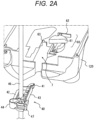
- Fig. 2 illustrates a cross-sectional perspective view of the liquid feeding pump 100 taken along line AA' in Fig. 1 and a first clip member 40.
- Fig. 3 illustrates an adapter 10 and a second clip member 50 according to an embodiment of the present application.
- Fig. 4 illustrates a cross-sectional perspective view of the liquid feeding pump 100 taken along line AA' in Fig. 1 in a state where the adapter 10 is mounted, and the second clip member 50.
- Fig. 5 illustrates a cross-sectional perspective view of the liquid feeding pump 100 taken along line AA' in Fig. 1 in a state where the adapter 10 is mounted, and the first clip member 40.
- the liquid feeding pump 100 includes a main body portion 120 and a door portion 110.
- the door portion 110 is attached to main body portion 120 to be openable and closable.
- the door portion 110 is opened with respect to the main body portion 120. Therefore, in Fig. 1 , the front surface of the main body portion 120 and the back surface of the door portion 110 are illustrated.
- the state in which the door portion 110 is open with respect to the main body portion 120 may be simply referred to as an "open state”.
- the state in which the door portion 110 is closed with respect to the main body portion 120 may be simply referred to as a "closed state".
- liquid feeding tubes 55 and 46 capable of feeding an infusion solution and a nutrient as different types of liquids can be installed.
- the liquid feeding pump 100 can feed the liquid in the liquid feeding tubes 55 and 46 by pressing the liquid feeding tubes 55 and 46 installed.
- the door portion 110 is brought into the closed state from a state where the door portion 110 is in the open state and the liquid feeding tubes 55 and 46 are disposed at predetermined positions of the main body portion 120.
- an infusion bag containing a liquid such as a predetermined medicinal solution is connected to the flow path upstream side (upper side of Figs.
- a clamp member and an indwelling catheter are connected to the flow path downstream side (lower side of Figs. 2A , 4A , 4B , and 5A ) of the liquid feeding tubes 55 and 46 with respect to the portion of the liquid feeding tubes 55 and 46 installed in the liquid feeding pump 100.
- the indwelling catheter is indwelled in a state of being punctured into a vein or the like of a patient.
- the liquid feeding pump 100 By using the liquid feeding pump 100, the flow rate (liquid feeding speed) or the like of the liquid in the liquid feeding tubes 55 and 46 per unit time is controlled. Therefore, the amount of the liquid in the infusion bag administered to the patient per unit time or the like can be controlled by the liquid feeding pump 100.
- the main body portion 120 includes an air bubble detection sensor unit 1, a pressing portion 2, a tube position defining unit 4, a closing sensor unit 5, and a mounting portion 7.
- the air bubble detection sensor unit 1 includes an ultrasonic transmission unit 8 and an ultrasonic reception unit 9.
- the air bubble detection sensor unit 1 detects the presence or absence of air bubbles in the liquid feeding tubes 55 and 46 in a state where the door portion 110 is in the closed state. More specifically, the liquid feeding tubes 55 and 46 are disposed between the ultrasonic transmission unit 8 and the ultrasonic reception unit 9, and the ultrasonic transmission unit 8 transmits a predetermined signal such as an ultrasonic wave to the ultrasonic reception unit 9. In a case where the signal intensity at which the ultrasonic signal is received is high, it is determined that no air bubble is detected, and when the signal intensity at which the ultrasonic signal is received is low, it is determined that an air bubble is detected.
- the pressing portion 2 includes a plurality of fingers 3.
- the plurality of fingers 3 is arranged from the flow path upstream side to the flow path downstream side of the liquid feeding tubes 55 and 46.
- Each of the plurality of fingers 3 can reciprocate in a direction facing a receiving portion 104 of the door portion 110 described later by the driving means.
- the plurality of fingers 3 is driven by the drive unit described above to sequentially press and close the liquid feeding tubes 55 and 46 from the flow path upstream side toward the flow path downstream side. As a result, the liquid feeding tubes 55 and 46 can perform peristaltic movement.
- the pressing portion 2 of the present embodiment includes eight fingers 3, but the number of fingers is not limited to eight in the present embodiment, and may be less than eight or nine or more.
- the finger 3 forms a contact body that comes into contact with the liquid feeding tubes 55 and 46, but for example, a contact body used in a so-called “roller pump” may be formed by squeezing the liquid feeding tubes 55 and 46 using a roller that revolves around a predetermined rotation central axis and is rotatable.
- the tube position defining unit 4 defines a position in a direction orthogonal to the central axis direction of the liquid feeding tubes 55 and 46 when the liquid feeding tubes 55 and 46 are mounted to the front surface of the main body portion 120.
- the closing sensor unit 5 includes a permanent magnet and a pickup for analog detection of a movement amount of the permanent magnet.
- the closing sensor unit 5 detects the closing state of the liquid feeding tubes 55 and 46 by detecting the movement amount of the permanent magnet that has moved in accordance with the internal pressure change accompanying the closing state of the liquid feeding tubes 55 and 46.
- the main body portion 120 may further include a handle 6 for the user to grip when carrying the liquid feeding pump 100.
- the mounting portion 7 is configured to be mountable to the first clip member 40 attached to the infusion tube as a liquid feeding tube 46 used for feeding the infusion solution. That is, the mounting portion 7 has a shape conforming to the first clip member 40. More specifically, the mounting portion 7 is configured in a manner that the mounting of the first clip member 40 can be detected by a detection unit 62 described later. Note that, in Fig. 2B , the liquid feeding tube 46 is omitted for convenience of description. This will be described later in detail.
- the adapter 10 can be attached to the mounting portion 7.
- the adapter 10 attached to the mounting portion 7 can be mounted to the second clip member 50 attached to a nutrient tube as a liquid feeding tube 55 used for feeding a nutrient.
- the adapter 10 is configured in a manner that the mounting of the second clip member 50 can be detected by the detection unit 62 described later in a state of being attached to the mounting portion 7.
- the adapter 10 is configured to enable mounting of the second clip member 50 to the liquid feeding pump 100 but disable mounting of the first clip member 40 to the liquid feeding pump 100.
- the adapter 10 has a shape that can be attached to the mounting portion 7, and is detachably attached to the mounting portion 7. Therefore, the adapter 10 is removed from the mounting portion 7 when the first clip member 40 is attached, and the adapter 10 is attached to the mounting portion 7 when the second clip member 50 is attached.
- the adapter 10 includes a cover member 20 and a detection assisting member 30.
- another form of adapter may be used.
- the door portion 110 includes a door housing 103.
- the door housing 103 is pivotably attached to a housing 12 of the main body portion 120 via a hinge portion 101.
- the door portion 110 of the present embodiment is configured to be openable and closable with respect to the main body portion 120.
- a door seal rubber 106 is disposed on the back surface side of the door portion 110.
- the door seal rubber 106 is formed of an elastomer, and prevents the medicinal solution from entering the inside of the main body portion 120 in the closed state of the door portion 110.
- a position holding portion 102 is disposed on the back surface side of the door portion 110.
- the position holding portion 102 positions the liquid feeding tubes 55 and 46 by abutting on the liquid feeding tubes 55 and 46.
- the receiving portion 104 is disposed on the back surface side of the door portion 110.
- the receiving portion 104 sandwiches the liquid feeding tubes 55 and 46 together with the pressing portion 2.
- the receiving portion 104 is disposed to face the pressing portion 2.
- the pressing portion 2 can press the liquid feeding tubes 55 and 46 sandwiched between the pressing portion 2 and the receiving portion 104 toward the receiving portion 104.
- the first clip member 40 is mounted to an infusion tube (hereinafter, this is referred to as an "infusion tube 46") as a liquid feeding tube 46 for feeding an infusion solution.
- the first clip member 40 is configured to be insertable into the insertion hole of the mounting portion 7.
- a detection mechanism 60 is provided when the liquid feeding pump 100 moves from the mounting portion 7 to the inside of the main body portion 120.
- the detection mechanism 60 includes a semicircular columnar rotation unit 61 and the detection unit 62, but a detection mechanism of another form may be used.
- the illustrated infusion tube 46 and the first clip member 40 constitute a liquid feeding set.
- Fig. 3 illustrates the adapter 10 that can be attached to the mounting portion 7 of the liquid feeding pump 100 and the second clip member 50 that can be attached to the mounting portion 7 via the adapter 10.
- the adapter 10 includes the cover member 20 and the detection assisting member 30.
- the form of the adapter 10 is not limited to the present embodiment.
- the cover member 20 includes a first portion 21, a second portion 25, an upstream tube fixing portion 23, and a downstream tube fixing portion 22.
- first portion 21 positioned on the left side of an insertion space 24 described later will be referred to as a "left portion 21”
- second portion 25 positioned on the right side of the insertion space 24 will be referred to as a "right portion 25”.
- the left portion 21, the right portion 25, the upstream tube fixing portion 23, and the downstream tube fixing portion 22 define the insertion space 24 that enables insertion of the second clip member 50 but does not disable insertion of the first clip member 40.
- the upstream tube fixing portion 23 and the downstream tube fixing portion 22 include a concave portion for fixing a nutrient tube (hereinafter, this is referred to as a "nutrient tube 55") as the liquid feeding tube 55 to which the second clip member 50 is attached.
- a nutrient tube 55 a nutrient tube
- the concave portion of the upstream tube fixing portion 23 and the concave portion of the downstream tube fixing portion 22 are aligned in a manner that the nutrient tube 55 extends substantially vertically in a state of being attached to the mounting portion 7 of the liquid feeding pump 100.
- the cover member 20 can be fixed to the main body portion 120 by fixing the left side surface of the left portion 21 and the right side surface of the right portion 25 to the vicinity of the inlet of the insertion hole of the mounting portion 7.
- the detection assisting member 30 includes a distal end portion 31, an elastic portion 32, and a member main body portion 33.
- the distal end portion 31 protrudes from the distal end surface of the member main body portion 33.
- the elastic portion 32 is disposed adjacent to the distal end portion 31, extends from the distal end surface of the member main body portion 33 in the same direction as the protruding direction of the distal end portion 31, and is configured to be elastically deformable in this direction.
- the elastic portion 32 is formed of, for example, a coil spring.
- the elastic portion 32 is attached to the mounting portion 7 of the liquid feeding pump 100 to be sandwiched between the distal end surface of the member main body portion 33 and a reaction force wall portion 63 of the main body portion 120 of the liquid feeding pump 100 (see Fig. 4B ).
- the detection assisting member 30 enables the detection unit 62 of the detection mechanism 60 to detect the second clip member 50. More specifically, the adapter 10 is attached to the mounting portion 7 in the order of the detection assisting member 30 and the cover member 20, and the second clip member 50 is inserted into the insertion space 24 defined by the cover member 20. As a result, the member main body portion 33 of the detection assisting member 30 is pressed by the second clip member 50. As a result, the elastic portion 32 is compressed and deformed between the member main body portion 33 and the reaction force wall portion 63.
- the distal end portion 31 protruding from the member main body portion 33 moves toward the side of the detection unit 62 through the opening adjacent to the reaction force wall portion 63 and extending toward the detection unit 62, and collides with the rotation unit 61 of the detection mechanism 60 provided at the depth of the insertion hole of the mounting portion 7.
- the rotation unit 61 rotates, and the position of the concave portion formed on the curved side surface on the arc of the rotation unit 61 coincides with the position of the detection unit 62.
- the detection unit 62 detects the second clip member 50.
- the detection assisting member 30 moves by being pressed by the second clip member 50, realizing the detection of the second clip member 50.
- the second clip member 50 includes a rear end portion 51, a clip main body portion 52, and a hook 53.
- the clip main body portion 52 is provided with an opening 54 through which the nutrient tube 55 penetrates.
- the hook 53 is configured to engage with the cover member 20 attached to the mounting portion 7.
- Fig. 4A illustrates a cross-sectional perspective view of the liquid feeding pump 100 taken along line AA' in Fig. 1 in a state where only the cover member 20 of the adapter 10 is mounted to the mounting portion 7, and the second clip member 50 mounted to the nutrient tube 55 that feeds nutrients.
- the detection assisting member 30 is attached to the mounting portion 7 before the cover member 20 is attached, but Fig. 4A illustrates a state in which only the cover member 20 is attached for convenience of description.
- the second clip member 50 is previously attached to the illustrated nutrient tube 55, and constitutes a liquid feeding set together with the nutrient tube 55.
- Fig. 4B is a cross-sectional perspective view of the liquid feeding pump 100 taken along line AA' in Fig. 1 in a state where both the cover member 20 and the detection assisting member 30 of the adapter 10 are mounted to the mounting portion 7.
- the elastic portion 32 is installed in a state of being sandwiched between the member main body portion 33 and the reaction force wall portion 63 of the main body portion 120 in the insertion hole of the mounting portion 7.
- the detection assisting member 30 cannot move further inward due to the elastic force of the elastic portion 32. Therefore, unless the member main body portion 33 is pressed against the elastic force of the elastic portion 32 to approach the rotation unit 61, the distal end portion 31 does not reach the rotation unit 61 of the detection mechanism 60 and does not contact the rotation unit 61.
- Fig. 4C illustrates a state in which the second clip member 50 is inserted into the insertion space 24 of the cover member 20 and the second clip member 50 presses the detection assisting member 30.
- Fig. 6 illustrates a plan view of the mounting portion 7 of the liquid feeding pump 100 and the detection mechanism 60.
- the detection assisting member 30 is pressed by the second clip member 50 to be detected by the detection unit 62.
- the member main body portion 33 of the detection assisting member 30 is pressed by the clip main body portion 52 of the second clip member 50.
- the member main body portion 33 moves in a direction approaching the reaction force wall portion 63 against the elastic force of the elastic portion 32.
- the distal end portion 31 disposed adjacent to the elastic portion 32 moves toward the rotation unit 61 of the detection mechanism 60 through the opening adjacent to the reaction force wall portion 63 and presses the rotation unit 61.
- the rotation unit 61 is rotated by pressing by the distal end portion 31, and the concave portion of the rotation unit 61 moves to the position of the detection unit 62.
- the detection unit 62 detects that the second clip member 50 is mounted to the mounting portion 7 via the adapter 10.
- the liquid feeding pump 100 to which the adapter 10 is attached can detect the mounting of the second clip member 50.
- the detection mechanism 60 recognizing the second clip member 50 the liquid feeding pump 100 can perform the liquid feeding operation in response to the request of the user.
- the detection assisting member 30 moves by being pressed by the second clip member 50, realizing the detection of the second clip member 50.
- the nutrient can be fed by the liquid feeding pump 100 for infusion.
- Fig. 5A illustrates a cross-sectional perspective view of the liquid feeding pump 100 taken along line AA' in Fig. 1 in a state where both the cover member 20 and the detection assisting member 30 of the adapter 10 is mounted to the mounting portion 7, and the first clip member 40 mounted to the infusion tube 46. Note that the first clip member 40 is previously attached to the illustrated infusion tube 46, and constitutes a liquid feeding set together with the infusion tube 46.
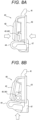
- Fig. 5B illustrates a case where the first clip member 40 is to be mounted in a state where both the cover member 20 and the detection assisting member 30 are mounted to the mounting portion 7 of the liquid feeding pump 100.
- the detection assisting member 30 is not in contact with the first clip member 40 and is not pressed by the first clip member 40, and thus is not detected by the detection unit 62.
- the insertion space 24 defined by the cover member 20 is defined to disable insertion of the first clip member 40. Therefore, the first clip member 40 cannot be inserted into the insertion space 24. Therefore, the first clip member 40 does not come into contact with the detection assisting member 30 positioned at the depth of the insertion space 24, and cannot press the detection assisting member 30.
- the detection assisting member 30 does not move against the elastic force of the elastic portion 32 and does not move to the inside of the main body portion 120. Therefore, the rotation unit 61 is not pressed by the distal end portion 31. Therefore, the detection unit 62 of the detection mechanism 60 cannot detect that the first clip member 40 is mounted to the liquid feeding pump 100.
- the cover member 20 of the adapter 10 prevents insertion of the first clip member 40, in a manner that the first clip member 40 cannot be mounted to the mounting portion 7.
- the insertion space 24 of the cover member 20 is defined to enable insertion of the second clip member 50 and disable insertion of the first clip member 40. Therefore, in a case where the cover member 20 is mounted to the mounting portion 7, the first clip member 40 cannot be mounted to the mounting portion 7. As a result, it is possible to prevent the infusion tube 46 from being erroneously mounted when the nutrient tube 55 is to be mounted to the liquid feeding pump 100.
- Fig. 7 is a cross-sectional perspective view of the liquid feeding pump 100 taken along line AA' in Fig. 1 in a state where only the cover member 20 of the adapter 10 is attached to the mounting portion 7.
- Fig. 7 illustrates a state in which the detection assisting member 30 is not disposed in the insertion hole of the mounting portion 7 and only the second clip member 50 is inserted into the insertion space 24 of the cover member 20.
- the depth of the insertion space 24 (the depth length from the inlet of the insertion hole of the mounting portion 7 of the main body portion 120 to the inside of the main body portion 120) is longer than the length of the second clip member 50.
- the second clip member 50 since the distal end of the second clip member 50 is substantially flat, the second clip member abuts on the reaction force wall portion 63 and cannot press the rotation unit 61 beyond the reaction force wall portion 63. Moreover, since the opening 54 through which the nutrient tube 55 penetrates is provided near the center of the clip main body portion 52 of the second clip member 50, even if only the second clip member 50 is inserted into the insertion space 24, the nutrient tube 55 penetrating the opening 54 of the second clip member 50 abuts on the housing 12 of the main body portion 120, in a manner that the second clip member 50 does not reach the rotation unit 61 and cannot press the rotation unit 61.
- the adapter 10 of the present embodiment does not enable the mounting of the second clip member 50 only with the cover member 20, but the adapter 10 is not limited to such a two-component configuration, and may be a one-component configuration, for example.
- Fig. 7 the description has been made based on the state in which only the cover member 20 of the adapter 10 is mounted to the mounting portion 7, but the same applies to the state in which the cover member 20 is not mounted to the mounting portion 7.
- Fig. 8 illustrates details of the first clip member 40 alone.
- the first clip member 40 includes the distal end portion 41, a left portion 42, a right portion 43, a first opening and closing portion 44 connected to the left portion 42, and a second opening and closing portion 47 connected to the right portion 43.
- “left and right” means left and right of the main body portion 120 in a front view in a state where the first clip member 40 is mounted to the mounting portion 7.
- the distal end portion 41 has the same shape as the distal end portion 31 of the detection assisting member 30.
- the first clip member 40 is made of a deformable material.
- the left portion 42, the right portion 43, and the first opening and closing portion 44 define an opening 45.
- the infusion tube 46 penetrates through the opening 45.
- the left portion 42 is displaceable with respect to the right portion 43 to change the size of the opening 45.
- the first opening and closing portion 44 and the second opening and closing portion 47 can be engaged with each other. In a state of not being pressed from the outside, the left portion 42 is disposed to form a predetermined angle with respect to the right portion 43.
- Fig. 8A illustrates a state in which the left portion 42 and the right portion 43 approach each other by being pressed in the direction indicated by the arrow.
- the first opening and closing portion 44 connected to the left portion 42 and the second opening and closing portion 47 connected to the right portion 43 are also brought close to and engaged with each other. Accordingly, the opening 45 is narrowed, and the infusion tube 46 in the opening 45 is closed.
- Fig. 8B illustrates a state in which the first opening and closing portion 44 is released from the engagement with the second opening and closing portion 47 by being pressed in the direction of the arrow.
- the left portion 42 connected to the first opening and closing portion 44 is displaced to be separated from the right portion 43 connected to the second opening and closing portion 47.
- the opening 45 expands, and the closing of the infusion tube 46 in the opening 45 is released.
- the mounting portion 7 of the liquid feeding pump 100 is configured to enable mounting of the first clip member 40.
- the mounting of the first clip member 40 is completed when the first clip member 40 is pushed into the insertion hole of the mounting portion 7 of the main body portion 120 and the distal end portion 41 of the first clip member 40 is detected by the detection unit 62.
- the first clip member 40 is mounted to the mounting portion 7 of the main body portion 120 in a state where the door portion 110 is opened with respect to the main body portion 120.
- the first clip member 40 is mounted to the mounting portion 7 in the state illustrated in Fig. 8A , and this state is maintained. Specifically, a force is received from both sides of the mounting portion 7 in the direction of the arrow in Fig. 8A .
- the left portion 42 and the right portion 43 of the first clip member 40 receive a force approaching each other. Since the left portion 42 is connected to the first opening and closing portion 44 and the right portion 43 is connected to the second opening and closing portion 47, the first opening and closing portion 44 and the second opening and closing portion 47 also approach each other when the left portion 42 and the right portion 43 receive a force to approach each other. As a result, the first opening and closing portion 44 and the second opening and closing portion 47 are engaged with each other. Therefore, the infusion tube 46' in the opening 45 is closed. This prevents an unintended flow of the infusion due to forgetting to close the clamp.
- the first clip member 40 After the first clip member 40 is mounted to the mounting portion 7, the first clip member 40 is sandwiched between the main body portion 120 and the door portion 110. Accordingly, the first clip member 40 receives a force in the direction of the arrow in Fig. 8B by the door portion 110. As a result, the engagement between the first opening and closing portion 44 and the second opening and closing portion 47 is released, and the left portion 42 is displaced to be separated from the right portion 43. As a result, the closing of the infusion tube 46 is released.
Landscapes
- Health & Medical Sciences (AREA)
- Heart & Thoracic Surgery (AREA)
- Hematology (AREA)
- Anesthesiology (AREA)
- Biomedical Technology (AREA)
- Engineering & Computer Science (AREA)
- Life Sciences & Earth Sciences (AREA)
- Animal Behavior & Ethology (AREA)
- General Health & Medical Sciences (AREA)
- Public Health (AREA)
- Veterinary Medicine (AREA)
- Pulmonology (AREA)
- Vascular Medicine (AREA)
- Infusion, Injection, And Reservoir Apparatuses (AREA)
Abstract
Description
- The present invention relates to a liquid feeding pump, an adapter, and a liquid feeding set.
- For example, a liquid feeding pump disclosed in Patent Literature 1 is known as a liquid feeding pump used for infusion. The liquid feeding pump for infusion described in Patent Literature 1 is usually used exclusively for infusion, and is not used for feeding nutrients, in order to suppress erroneous attachment of a nutrient tube for feeding nutrients and an infusion tube for feeding an infusion solution.
- Patent Literature 1:
JP 2011-212112 A - The fact that the liquid feeding pump described in Patent Literature 1 can be used for feeding nutrients brings about an advantage that it is not necessary to purchase a liquid feeding pump different from the liquid feeding pump for feeding the infusion solution in order to feed the nutrients.
- An object of the present invention is to provide a liquid feeding pump capable of feeding different types of liquids while preventing erroneous attachment of tubes for feeding different types of liquids. In addition, an object of the present invention is to provide an adapter for enabling feeding different types of liquids to a liquid feeding pump. Furthermore, an object of the present invention is to provide a liquid feeding set that can be mounted to a liquid feeding pump only via the adapter described above.
- According to a first aspect of the present invention, a liquid feeding pump for feeding liquid in a liquid feeding tube is provided. The liquid feeding pump includes: a mounting portion to which a first clip member mounted to the liquid feeding tube is mountable; an adapter detachably attachable to the mounting portion; and a detection unit that detects mounting of the first clip member to the mounting portion. The adapter has a shape that disables detection of mounting of the first clip member by the detection unit and enables detection of mounting of a second clip member having a shape different from a shape of the first clip member by the detection unit.
- According to a preferred embodiment of the liquid feeding pump of the present invention, the adapter defines an insertion space formed to disable insertion of the first clip member and enable insertion of the second clip member.
- According to a preferred embodiment of the liquid feeding pump of the present invention, the adapter includes a cover member that defines the insertion space, and a detection assisting member that is detected by the detection unit by being pressed and moved or deformed by the second clip member inserted into the insertion space.
- According to a preferred embodiment of the liquid feeding pump of the present invention, the first clip member is mounted to an infusion tube that feeds an infusion solution.
- According to a preferred embodiment of the liquid feeding pump of the present invention, the second clip member is mounted to a nutrient tube that feeds a nutrient.
- According to a preferred embodiment of the liquid feeding pump of the present invention, the liquid feeding pump includes a main body portion that controls feeding of the liquid, and a door portion pivotably connected to the main body portion to sandwich the liquid feeding tube together with the main body portion When the first clip member is mounted to the mounting portion in a state where the door portion is opened with respect to the main body portion, the liquid feeding tube to which the first clip member is mounted is closed.
- According to a preferred embodiment of the liquid feeding pump of the present invention, after the first clip member is mounted to the mounting portion, the door portion is closed with respect to the main body portion, and when the liquid feeding tube is sandwiched between the main body portion and the door portion, closing of the liquid feeding tube is released.
- According to a second aspect of the present invention, there is provided an adapter used in a liquid feeding pump including a mounting portion to which a first clip member mounted to the liquid feeding tube is mountable; and a detection unit that detects mounting of the first clip member to the mounting portion. The adapter has a shape that disables detection of mounting of the first clip member by the detection unit and enables detection of mounting of a second clip member having a shape different from a shape of the first clip member by the detection unit, and the adapter is configured to be detachably attached to the mounting portion.
- A preferred embodiment of the adapter of the present invention defines an insertion space formed to disable insertion of the first clip member and enable insertion of the second clip member.
- A preferred embodiment of the liquid feeding pump of the present invention includes a cover member that defines the insertion space, and a detection assisting member that is detected by the detection unit by being pressed and moved or deformed by the second clip member inserted into the insertion space.
- According to a third aspect of the present invention, a liquid feeding set used in a liquid feeding pump is provided. The liquid feeding set includes: a liquid feeding tube; and a clip member attached to the liquid feeding tube. The clip member has a shape that cannot be mounted to a mounting portion of the liquid feeding pump and can be mounted to the liquid feeding pump only via an adapter attached to the mounting portion.
- According to the present invention, it is possible to provide a liquid feeding pump capable of feeding different types of liquids while preventing erroneous attachment of tubes for feeding different types of liquids. In addition, according to the present invention, it is possible to provide an adapter for enabling feeding different types of liquids to a liquid feeding pump. Furthermore, according to the present invention, it is possible to provide a liquid feeding set that can be mounted to a liquid feeding pump only via the adapter described above.
-
-
Fig. 1 illustrates a front view of a liquid feeding pump according to an embodiment of the present application. -
Fig. 2A illustrates a cross-sectional perspective view of the liquid feeding pump taken along line AA' inFig. 1 , and a first clip member before being mounted to a mounting portion of the liquid feeding pump illustrated inFig. 1 . -
Fig. 2B illustrates a state in which the first clip member is completely mounted to the mounting portion of the liquid feeding pump from the state illustrated inFig. 2A . -
Fig. 3 illustrates an adapter according to an embodiment of the present application and a second clip member mountable to the adapter. -
Fig. 4A illustrates a cross-sectional perspective view of the liquid feeding pump taken along line AA' inFig. 1 in a state where only a cover member of the adapter illustrated inFig. 3 is mounted, and the second clip member before being mounted to the adapter. -
Fig. 4B illustrates a cross-sectional perspective view of the liquid feeding pump taken along line AA' inFig. 1 in a state where both the cover member and a detection assisting member constituting the adapter illustrated inFig. 3 are mounted, and the second clip member before being mounted to the adapter. -
Fig. 4C illustrates a state in which the second clip member is completely mounted to the adapter mounted to the mounting portion of the liquid feeding pump from the state illustrated inFig. 4B . -
Fig. 5A illustrates a cross-sectional perspective view of the liquid feeding pump taken along line AA' inFig. 1 in a state where both the cover member and the detection assisting member constituting the adapter illustrated inFig. 3 are mounted, and the first clip member. -
Fig. 5B illustrates that the first clip member cannot be mounted to the adapter in the state illustrated inFig. 5A . -
Fig. 6 illustrates a plan view of the mounting portion of the liquid feeding pump and a detection mechanism according to the embodiment of the present application. -
Fig. 7 illustrates a cross-sectional perspective view of the liquid feeding pump taken along line AA' inFig. 1 in the state where only the cover member of the adapter illustrated inFig. 3 is mounted, and the second clip member inserted into an insertion space of the cover member. -
Fig. 8A illustrates one form of the first clip member illustrated inFig. 2A . -
Fig. 8B illustrates another form of the first clip member illustrated inFig. 2A . -
Fig. 1 illustrates a front view of aliquid feeding pump 100 according to an embodiment of the present application.Fig. 2 illustrates a cross-sectional perspective view of theliquid feeding pump 100 taken along line AA' inFig. 1 and afirst clip member 40.Fig. 3 illustrates anadapter 10 and asecond clip member 50 according to an embodiment of the present application.Fig. 4 illustrates a cross-sectional perspective view of theliquid feeding pump 100 taken along line AA' inFig. 1 in a state where theadapter 10 is mounted, and thesecond clip member 50.Fig. 5 illustrates a cross-sectional perspective view of theliquid feeding pump 100 taken along line AA' inFig. 1 in a state where theadapter 10 is mounted, and thefirst clip member 40. - The
liquid feeding pump 100 includes amain body portion 120 and adoor portion 110. Thedoor portion 110 is attached tomain body portion 120 to be openable and closable. In theliquid feeding pump 100 illustrated inFig. 1 , thedoor portion 110 is opened with respect to themain body portion 120. Therefore, inFig. 1 , the front surface of themain body portion 120 and the back surface of thedoor portion 110 are illustrated. Hereinafter, the state in which thedoor portion 110 is open with respect to themain body portion 120 may be simply referred to as an "open state". In addition, the state in which thedoor portion 110 is closed with respect to themain body portion 120 may be simply referred to as a "closed state". - In the
liquid feeding pump 100,liquid feeding tubes liquid feeding pump 100 can feed the liquid in theliquid feeding tubes liquid feeding tubes liquid feeding pump 100 of the present embodiment, thedoor portion 110 is brought into the closed state from a state where thedoor portion 110 is in the open state and theliquid feeding tubes main body portion 120. Thus, the installation of theliquid feeding tubes liquid feeding pump 100 is completed. For example, an infusion bag containing a liquid such as a predetermined medicinal solution is connected to the flow path upstream side (upper side ofFigs. 2A ,4A ,4B , and5A ) of theliquid feeding tubes liquid feeding tubes liquid feeding pump 100. In addition, for example, a clamp member and an indwelling catheter are connected to the flow path downstream side (lower side ofFigs. 2A ,4A ,4B , and5A ) of theliquid feeding tubes liquid feeding tubes liquid feeding pump 100. The indwelling catheter is indwelled in a state of being punctured into a vein or the like of a patient. By using theliquid feeding pump 100, the flow rate (liquid feeding speed) or the like of the liquid in theliquid feeding tubes liquid feeding pump 100. - As illustrated in
Fig. 1 , themain body portion 120 includes an air bubble detection sensor unit 1, apressing portion 2, a tubeposition defining unit 4, aclosing sensor unit 5, and a mountingportion 7. - The air bubble detection sensor unit 1 includes an ultrasonic transmission unit 8 and an
ultrasonic reception unit 9. The air bubble detection sensor unit 1 detects the presence or absence of air bubbles in theliquid feeding tubes door portion 110 is in the closed state. More specifically, theliquid feeding tubes ultrasonic reception unit 9, and the ultrasonic transmission unit 8 transmits a predetermined signal such as an ultrasonic wave to theultrasonic reception unit 9. In a case where the signal intensity at which the ultrasonic signal is received is high, it is determined that no air bubble is detected, and when the signal intensity at which the ultrasonic signal is received is low, it is determined that an air bubble is detected. - The
pressing portion 2 includes a plurality offingers 3. The plurality offingers 3 is arranged from the flow path upstream side to the flow path downstream side of theliquid feeding tubes fingers 3 can reciprocate in a direction facing a receivingportion 104 of thedoor portion 110 described later by the driving means. The plurality offingers 3 is driven by the drive unit described above to sequentially press and close theliquid feeding tubes liquid feeding tubes pressing portion 2 of the present embodiment includes eightfingers 3, but the number of fingers is not limited to eight in the present embodiment, and may be less than eight or nine or more. In addition, in thepressing portion 2 of the present embodiment, thefinger 3 forms a contact body that comes into contact with theliquid feeding tubes liquid feeding tubes - The tube
position defining unit 4 defines a position in a direction orthogonal to the central axis direction of theliquid feeding tubes liquid feeding tubes main body portion 120. - The
closing sensor unit 5 includes a permanent magnet and a pickup for analog detection of a movement amount of the permanent magnet. For example, theclosing sensor unit 5 detects the closing state of theliquid feeding tubes liquid feeding tubes - As illustrated in
Fig. 1 , themain body portion 120 may further include ahandle 6 for the user to grip when carrying theliquid feeding pump 100. - As illustrated in
Figs. 2A and2B , the mountingportion 7 is configured to be mountable to thefirst clip member 40 attached to the infusion tube as aliquid feeding tube 46 used for feeding the infusion solution. That is, the mountingportion 7 has a shape conforming to thefirst clip member 40. More specifically, the mountingportion 7 is configured in a manner that the mounting of thefirst clip member 40 can be detected by adetection unit 62 described later. Note that, inFig. 2B , theliquid feeding tube 46 is omitted for convenience of description. This will be described later in detail. - As illustrated in
Figs. 4A ,4B ,4C ,5A , and5B , theadapter 10 can be attached to the mountingportion 7. Theadapter 10 attached to the mountingportion 7 can be mounted to thesecond clip member 50 attached to a nutrient tube as aliquid feeding tube 55 used for feeding a nutrient. More specifically, theadapter 10 is configured in a manner that the mounting of thesecond clip member 50 can be detected by thedetection unit 62 described later in a state of being attached to the mountingportion 7. In addition, theadapter 10 is configured to enable mounting of thesecond clip member 50 to theliquid feeding pump 100 but disable mounting of thefirst clip member 40 to theliquid feeding pump 100. Theadapter 10 has a shape that can be attached to the mountingportion 7, and is detachably attached to the mountingportion 7. Therefore, theadapter 10 is removed from the mountingportion 7 when thefirst clip member 40 is attached, and theadapter 10 is attached to the mountingportion 7 when thesecond clip member 50 is attached. As described later, in the present embodiment, theadapter 10 includes acover member 20 and adetection assisting member 30. However, another form of adapter may be used. - As illustrated in
Fig. 1 , thedoor portion 110 includes adoor housing 103. Thedoor housing 103 is pivotably attached to ahousing 12 of themain body portion 120 via ahinge portion 101. In this manner, thedoor portion 110 of the present embodiment is configured to be openable and closable with respect to themain body portion 120. - On the back surface side of the
door portion 110, adoor seal rubber 106 is disposed. Thedoor seal rubber 106 is formed of an elastomer, and prevents the medicinal solution from entering the inside of themain body portion 120 in the closed state of thedoor portion 110. - In addition, a
position holding portion 102 is disposed on the back surface side of thedoor portion 110. When thedoor portion 110 is closed with respect to themain body portion 120, theposition holding portion 102 positions theliquid feeding tubes liquid feeding tubes - In addition, the receiving
portion 104 is disposed on the back surface side of thedoor portion 110. The receivingportion 104 sandwiches theliquid feeding tubes pressing portion 2. In addition, the receivingportion 104 is disposed to face thepressing portion 2. Thepressing portion 2 can press theliquid feeding tubes pressing portion 2 and the receivingportion 104 toward the receivingportion 104. - Next, a configuration for detecting mounting of the
first clip member 40 and thesecond clip member 50 in theliquid feeding pump 100 will be described. As illustrated inFig. 2A , thefirst clip member 40 is mounted to an infusion tube (hereinafter, this is referred to as an "infusion tube 46") as aliquid feeding tube 46 for feeding an infusion solution. As illustrated inFig. 2B , thefirst clip member 40 is configured to be insertable into the insertion hole of the mountingportion 7. Adetection mechanism 60 is provided when theliquid feeding pump 100 moves from the mountingportion 7 to the inside of themain body portion 120. In the present embodiment, thedetection mechanism 60 includes a semicircularcolumnar rotation unit 61 and thedetection unit 62, but a detection mechanism of another form may be used. The illustratedinfusion tube 46 and thefirst clip member 40 constitute a liquid feeding set. - Referring to
Fig. 2B , when thefirst clip member 40 is attached to the mountingportion 7, a protrudingdistal end portion 41 of thefirst clip member 40 collides with theradial rotation unit 61 of thedetection mechanism 60. By the collision, the semicircularcolumnar rotation unit 61 rotates about a central axis positioned at a substantially circular central portion of the semicircular bottom surface. When therotation unit 61 rotates, the position of the concave portion formed on the curved side surface on the arc of therotation unit 61 coincides with the position of thedetection unit 62. As a result, thedetection unit 62 of thedetection mechanism 60 detects thefirst clip member 40. Accordingly, theliquid feeding pump 100 can detect that thefirst clip member 40 is mounted to the mountingportion 7. - As described above,
Fig. 3 illustrates theadapter 10 that can be attached to the mountingportion 7 of theliquid feeding pump 100 and thesecond clip member 50 that can be attached to the mountingportion 7 via theadapter 10. In the present embodiment, theadapter 10 includes thecover member 20 and thedetection assisting member 30. However, the form of theadapter 10 is not limited to the present embodiment. - The
cover member 20 includes afirst portion 21, asecond portion 25, an upstreamtube fixing portion 23, and a downstreamtube fixing portion 22. Hereinafter, for convenience of description, in a front view of themain body portion 120 in a state where thecover member 20 is attached to the mountingportion 7, thefirst portion 21 positioned on the left side of aninsertion space 24 described later will be referred to as a "left portion 21", and thesecond portion 25 positioned on the right side of theinsertion space 24 will be referred to as a "right portion 25". Theleft portion 21, theright portion 25, the upstreamtube fixing portion 23, and the downstreamtube fixing portion 22 define theinsertion space 24 that enables insertion of thesecond clip member 50 but does not disable insertion of thefirst clip member 40. The upstreamtube fixing portion 23 and the downstreamtube fixing portion 22 include a concave portion for fixing a nutrient tube (hereinafter, this is referred to as a "nutrient tube 55") as theliquid feeding tube 55 to which thesecond clip member 50 is attached. In thecover member 20 of the present embodiment, the concave portion of the upstreamtube fixing portion 23 and the concave portion of the downstreamtube fixing portion 22 are aligned in a manner that thenutrient tube 55 extends substantially vertically in a state of being attached to the mountingportion 7 of theliquid feeding pump 100. In addition, thecover member 20 can be fixed to themain body portion 120 by fixing the left side surface of theleft portion 21 and the right side surface of theright portion 25 to the vicinity of the inlet of the insertion hole of the mountingportion 7. - The
detection assisting member 30 includes adistal end portion 31, anelastic portion 32, and a membermain body portion 33. Thedistal end portion 31 protrudes from the distal end surface of the membermain body portion 33. In addition, theelastic portion 32 is disposed adjacent to thedistal end portion 31, extends from the distal end surface of the membermain body portion 33 in the same direction as the protruding direction of thedistal end portion 31, and is configured to be elastically deformable in this direction. Theelastic portion 32 is formed of, for example, a coil spring. Theelastic portion 32 is attached to the mountingportion 7 of theliquid feeding pump 100 to be sandwiched between the distal end surface of the membermain body portion 33 and a reactionforce wall portion 63 of themain body portion 120 of the liquid feeding pump 100 (seeFig. 4B ). Thedetection assisting member 30 enables thedetection unit 62 of thedetection mechanism 60 to detect thesecond clip member 50. More specifically, theadapter 10 is attached to the mountingportion 7 in the order of thedetection assisting member 30 and thecover member 20, and thesecond clip member 50 is inserted into theinsertion space 24 defined by thecover member 20. As a result, the membermain body portion 33 of thedetection assisting member 30 is pressed by thesecond clip member 50. As a result, theelastic portion 32 is compressed and deformed between the membermain body portion 33 and the reactionforce wall portion 63. - The
distal end portion 31 protruding from the membermain body portion 33 moves toward the side of thedetection unit 62 through the opening adjacent to the reactionforce wall portion 63 and extending toward thedetection unit 62, and collides with therotation unit 61 of thedetection mechanism 60 provided at the depth of the insertion hole of the mountingportion 7. When thedistal end portion 31 collides with therotation unit 61, therotation unit 61 rotates, and the position of the concave portion formed on the curved side surface on the arc of therotation unit 61 coincides with the position of thedetection unit 62. As a result, thedetection unit 62 detects thesecond clip member 50. As described above, in the present embodiment, thedetection assisting member 30 moves by being pressed by thesecond clip member 50, realizing the detection of thesecond clip member 50. - The
second clip member 50 includes arear end portion 51, a clipmain body portion 52, and ahook 53. The clipmain body portion 52 is provided with anopening 54 through which thenutrient tube 55 penetrates. Thehook 53 is configured to engage with thecover member 20 attached to the mountingportion 7. -
Fig. 4A illustrates a cross-sectional perspective view of theliquid feeding pump 100 taken along line AA' inFig. 1 in a state where only thecover member 20 of theadapter 10 is mounted to the mountingportion 7, and thesecond clip member 50 mounted to thenutrient tube 55 that feeds nutrients. Originally, thedetection assisting member 30 is attached to the mountingportion 7 before thecover member 20 is attached, butFig. 4A illustrates a state in which only thecover member 20 is attached for convenience of description. Note that thesecond clip member 50 is previously attached to the illustratednutrient tube 55, and constitutes a liquid feeding set together with thenutrient tube 55. -
Fig. 4B is a cross-sectional perspective view of theliquid feeding pump 100 taken along line AA' inFig. 1 in a state where both thecover member 20 and thedetection assisting member 30 of theadapter 10 are mounted to the mountingportion 7. As illustrated inFig. 4B , theelastic portion 32 is installed in a state of being sandwiched between the membermain body portion 33 and the reactionforce wall portion 63 of themain body portion 120 in the insertion hole of the mountingportion 7. Thedetection assisting member 30 cannot move further inward due to the elastic force of theelastic portion 32. Therefore, unless the membermain body portion 33 is pressed against the elastic force of theelastic portion 32 to approach therotation unit 61, thedistal end portion 31 does not reach therotation unit 61 of thedetection mechanism 60 and does not contact therotation unit 61. -
Fig. 4C illustrates a state in which thesecond clip member 50 is inserted into theinsertion space 24 of thecover member 20 and thesecond clip member 50 presses thedetection assisting member 30. In addition,Fig. 6 illustrates a plan view of the mountingportion 7 of theliquid feeding pump 100 and thedetection mechanism 60. As illustrated inFigs. 4C and6 , thedetection assisting member 30 is pressed by thesecond clip member 50 to be detected by thedetection unit 62. Specifically, the membermain body portion 33 of thedetection assisting member 30 is pressed by the clipmain body portion 52 of thesecond clip member 50. As a result, the membermain body portion 33 moves in a direction approaching the reactionforce wall portion 63 against the elastic force of theelastic portion 32. Therefore, thedistal end portion 31 disposed adjacent to theelastic portion 32 moves toward therotation unit 61 of thedetection mechanism 60 through the opening adjacent to the reactionforce wall portion 63 and presses therotation unit 61. Therotation unit 61 is rotated by pressing by thedistal end portion 31, and the concave portion of therotation unit 61 moves to the position of thedetection unit 62. Accordingly, thedetection unit 62 detects that thesecond clip member 50 is mounted to the mountingportion 7 via theadapter 10. As described above, theliquid feeding pump 100 to which theadapter 10 is attached can detect the mounting of thesecond clip member 50. In response to thedetection mechanism 60 recognizing thesecond clip member 50, theliquid feeding pump 100 can perform the liquid feeding operation in response to the request of the user. As described above, in the present embodiment, thedetection assisting member 30 moves by being pressed by thesecond clip member 50, realizing the detection of thesecond clip member 50. As a result, the nutrient can be fed by theliquid feeding pump 100 for infusion. -
Fig. 5A illustrates a cross-sectional perspective view of theliquid feeding pump 100 taken along line AA' inFig. 1 in a state where both thecover member 20 and thedetection assisting member 30 of theadapter 10 is mounted to the mountingportion 7, and thefirst clip member 40 mounted to theinfusion tube 46. Note that thefirst clip member 40 is previously attached to the illustratedinfusion tube 46, and constitutes a liquid feeding set together with theinfusion tube 46. -
Fig. 5B illustrates a case where thefirst clip member 40 is to be mounted in a state where both thecover member 20 and thedetection assisting member 30 are mounted to the mountingportion 7 of theliquid feeding pump 100. Thedetection assisting member 30 is not in contact with thefirst clip member 40 and is not pressed by thefirst clip member 40, and thus is not detected by thedetection unit 62. Specifically, theinsertion space 24 defined by thecover member 20 is defined to disable insertion of thefirst clip member 40. Therefore, thefirst clip member 40 cannot be inserted into theinsertion space 24. Therefore, thefirst clip member 40 does not come into contact with thedetection assisting member 30 positioned at the depth of theinsertion space 24, and cannot press thedetection assisting member 30. Therefore, thedetection assisting member 30 does not move against the elastic force of theelastic portion 32 and does not move to the inside of themain body portion 120. Therefore, therotation unit 61 is not pressed by thedistal end portion 31. Therefore, thedetection unit 62 of thedetection mechanism 60 cannot detect that thefirst clip member 40 is mounted to theliquid feeding pump 100. As described above, in the present embodiment, thecover member 20 of theadapter 10 prevents insertion of thefirst clip member 40, in a manner that thefirst clip member 40 cannot be mounted to the mountingportion 7. - As described above, the
insertion space 24 of thecover member 20 is defined to enable insertion of thesecond clip member 50 and disable insertion of thefirst clip member 40. Therefore, in a case where thecover member 20 is mounted to the mountingportion 7, thefirst clip member 40 cannot be mounted to the mountingportion 7. As a result, it is possible to prevent theinfusion tube 46 from being erroneously mounted when thenutrient tube 55 is to be mounted to theliquid feeding pump 100. -
Fig. 7 is a cross-sectional perspective view of theliquid feeding pump 100 taken along line AA' inFig. 1 in a state where only thecover member 20 of theadapter 10 is attached to the mountingportion 7.Fig. 7 illustrates a state in which thedetection assisting member 30 is not disposed in the insertion hole of the mountingportion 7 and only thesecond clip member 50 is inserted into theinsertion space 24 of thecover member 20. The depth of the insertion space 24 (the depth length from the inlet of the insertion hole of the mountingportion 7 of themain body portion 120 to the inside of the main body portion 120) is longer than the length of thesecond clip member 50. In addition, since the distal end of thesecond clip member 50 is substantially flat, the second clip member abuts on the reactionforce wall portion 63 and cannot press therotation unit 61 beyond the reactionforce wall portion 63. Moreover, since theopening 54 through which thenutrient tube 55 penetrates is provided near the center of the clipmain body portion 52 of thesecond clip member 50, even if only thesecond clip member 50 is inserted into theinsertion space 24, thenutrient tube 55 penetrating theopening 54 of thesecond clip member 50 abuts on thehousing 12 of themain body portion 120, in a manner that thesecond clip member 50 does not reach therotation unit 61 and cannot press therotation unit 61. As described above, theadapter 10 of the present embodiment does not enable the mounting of thesecond clip member 50 only with thecover member 20, but theadapter 10 is not limited to such a two-component configuration, and may be a one-component configuration, for example. InFig. 7 , the description has been made based on the state in which only thecover member 20 of theadapter 10 is mounted to the mountingportion 7, but the same applies to the state in which thecover member 20 is not mounted to the mountingportion 7. -
Fig. 8 illustrates details of thefirst clip member 40 alone. Thefirst clip member 40 includes thedistal end portion 41, aleft portion 42, aright portion 43, a first opening and closingportion 44 connected to theleft portion 42, and a second opening and closingportion 47 connected to theright portion 43. Here, similarly to thecover member 20 described above, "left and right" means left and right of themain body portion 120 in a front view in a state where thefirst clip member 40 is mounted to the mountingportion 7. Thedistal end portion 41 has the same shape as thedistal end portion 31 of thedetection assisting member 30. Thefirst clip member 40 is made of a deformable material. Theleft portion 42, theright portion 43, and the first opening and closingportion 44 define anopening 45. When thefirst clip member 40 is attached to theinfusion tube 46, theinfusion tube 46 penetrates through theopening 45. Theleft portion 42 is displaceable with respect to theright portion 43 to change the size of theopening 45. The first opening and closingportion 44 and the second opening and closingportion 47 can be engaged with each other. In a state of not being pressed from the outside, theleft portion 42 is disposed to form a predetermined angle with respect to theright portion 43. -
Fig. 8A illustrates a state in which theleft portion 42 and theright portion 43 approach each other by being pressed in the direction indicated by the arrow. As a result, the first opening and closingportion 44 connected to theleft portion 42 and the second opening and closingportion 47 connected to theright portion 43 are also brought close to and engaged with each other. Accordingly, theopening 45 is narrowed, and theinfusion tube 46 in theopening 45 is closed. -
Fig. 8B illustrates a state in which the first opening and closingportion 44 is released from the engagement with the second opening and closingportion 47 by being pressed in the direction of the arrow. As a result, theleft portion 42 connected to the first opening and closingportion 44 is displaced to be separated from theright portion 43 connected to the second opening and closingportion 47. Accordingly, theopening 45 expands, and the closing of theinfusion tube 46 in theopening 45 is released. - As described above, the mounting
portion 7 of theliquid feeding pump 100 is configured to enable mounting of thefirst clip member 40. The mounting of thefirst clip member 40 is completed when thefirst clip member 40 is pushed into the insertion hole of the mountingportion 7 of themain body portion 120 and thedistal end portion 41 of thefirst clip member 40 is detected by thedetection unit 62. Thefirst clip member 40 is mounted to the mountingportion 7 of themain body portion 120 in a state where thedoor portion 110 is opened with respect to themain body portion 120. At this time, thefirst clip member 40 is mounted to the mountingportion 7 in the state illustrated inFig. 8A , and this state is maintained. Specifically, a force is received from both sides of the mountingportion 7 in the direction of the arrow inFig. 8A . As a result, theleft portion 42 and theright portion 43 of thefirst clip member 40 receive a force approaching each other. Since theleft portion 42 is connected to the first opening and closingportion 44 and theright portion 43 is connected to the second opening and closingportion 47, the first opening and closingportion 44 and the second opening and closingportion 47 also approach each other when theleft portion 42 and theright portion 43 receive a force to approach each other. As a result, the first opening and closingportion 44 and the second opening and closingportion 47 are engaged with each other. Therefore, the infusion tube 46' in theopening 45 is closed. This prevents an unintended flow of the infusion due to forgetting to close the clamp. - After the
first clip member 40 is mounted to the mountingportion 7, thefirst clip member 40 is sandwiched between themain body portion 120 and thedoor portion 110. Accordingly, thefirst clip member 40 receives a force in the direction of the arrow inFig. 8B by thedoor portion 110. As a result, the engagement between the first opening and closingportion 44 and the second opening and closingportion 47 is released, and theleft portion 42 is displaced to be separated from theright portion 43. As a result, the closing of theinfusion tube 46 is released. -
- 1
- Air bubble detection sensor
- 2
- Pressing portion
- 3
- Finger
- 4
- Tube position defining unit
- 5
- Closing sensor unit
- 6
- Handle
- 7
- Mounting portion
- 8
- Ultrasonic transmission unit
- 9
- Ultrasonic reception unit
- 10
- Adapter
- 12
- Housing
- 20
- Cover member
- 21
- First portion (left portion)
- 22
- Downstream tube fixing portion
- 23
- Upstream tube fixing portion
- 24
- Insertion space
- 25
- Second portion (right portion)
- 30
- Detection assisting member
- 31
- Distal end portion
- 32
- Elastic portion
- 33
- Member main body portion
- 40
- First clip member
- 41
- Distal end portion
- 42
- Left portion
- 43
- Right portion
- 44
- First opening and closing portion
- 45
- Opening
- 46
- Liquid feeding tube (infusion tube)
- 47
- Second opening and closing portion
- 50
- Second clip member
- 51
- Rear end portion
- 52
- Clip main body portion
- 53
- Hook
- 54
- Opening
- 55
- Liquid feeding tube (nutrient tube)
- 60
- Detection mechanism
- 61
- Rotation unit
- 62
- Detection unit
- 63
- Reaction force wall portion
- 101
- Hinge portion
- 102
- Position holding portion
- 103
- Door housing
- 104
- Receiving portion
- 106
- Door seal rubber
- 110
- Door portion
- 120
- Main body portion
Claims (11)
- A liquid feeding pump for feeding liquid in a liquid feeding tube, the liquid feeding pump comprising:a mounting portion to which a first clip member mounted to the liquid feeding tube is mountable;an adapter detachably attachable to the mounting portion; anda detection unit that detects mounting of the first clip member to the mounting portion, whereinthe adapter has a shape that disables detection of mounting of the first clip member by the detection unit and enables detection of mounting of a second clip member having a shape different from a shape of the first clip member by the detection unit.
- The liquid feeding pump according to claim 1, wherein the adapter defines an insertion space formed to disable insertion of the first clip member and enable insertion of the second clip member.
- The liquid feeding pump according to claim 2, wherein the adapter includes a cover member that defines the insertion space, and a detection assisting member that is detected by the detection unit by being pressed and moved or deformed by the second clip member inserted into the insertion space.
- The liquid feeding pump according to any one of claims 1 to 3, wherein the first clip member is mounted to an infusion tube that feeds an infusion solution.
- The liquid feeding pump according to any one of claims 1 to 4, wherein the second clip member is mounted to a nutrient tube that feeds a nutrient.
- The liquid feeding pump according to any one of claims 1 to 5, comprising:a main body portion that controls feeding of the liquid, and a door portion pivotably connected to the main body portion to sandwich the liquid feeding tube together with the main body portion, whereinwhen the first clip member is mounted to the mounting portion in a state where the door portion is opened with respect to the main body portion, the liquid feeding tube to which the first clip member is mounted is closed.
- The liquid feeding pump according to claim 6, wherein after the first clip member is mounted to the mounting portion, the door portion is closed with respect to the main body portion, and when the liquid feeding tube is sandwiched between the main body portion and the door portion, closing of the liquid feeding tube is released.
- An adapter used in a liquid feeding pump including a mounting portion to which a first clip member mounted to a liquid feeding tube is mountable, and a detection unit that detects mounting of the first clip member to the mounting portion, the adapter havinga shape that disables detection of mounting of the first clip member by the detection unit and enables detection of mounting of a second clip member having a shape different from a shape of the first clip member by the detection unit, whereinthe adapter is configured to be detachably attached to the mounting portion.
- The adapter according to claim 8, wherein the adapter defines an insertion space formed to disable insertion of the first clip member and enable insertion of the second clip member.
- The adapter according to claim 9 comprising: a cover member that defines the insertion space; and a detection assisting member that is detected by the detection unit by being pressed and moved or deformed by the second clip member inserted into the insertion space.
- A liquid feeding set used in a liquid feeding pump, the liquid feeding set comprising: a liquid feeding tube; and a clip member attached to the liquid feeding tube, wherein
the clip member has a shape that cannot be mounted to a mounting portion of the liquid feeding pump and can be mounted to the liquid feeding pump only via an adapter attached to the mounting portion.
Applications Claiming Priority (2)
| Application Number | Priority Date | Filing Date | Title |
|---|---|---|---|
| JP2020205380 | 2020-12-10 | ||
| PCT/JP2021/039149 WO2022123933A1 (en) | 2020-12-10 | 2021-10-22 | Liquid feeding pump, adapter and liquid feeding set |
Publications (3)
| Publication Number | Publication Date |
|---|---|
| EP4230238A1 true EP4230238A1 (en) | 2023-08-23 |
| EP4230238A4 EP4230238A4 (en) | 2024-04-10 |
| EP4230238B1 EP4230238B1 (en) | 2025-03-12 |
Family
ID=81973635
Family Applications (1)
| Application Number | Title | Priority Date | Filing Date |
|---|---|---|---|
| EP21903037.6A Active EP4230238B1 (en) | 2020-12-10 | 2021-10-22 | Liquid feeding pump, adapter and liquid feeding set |
Country Status (5)
| Country | Link |
|---|---|
| US (1) | US20230321346A1 (en) |
| EP (1) | EP4230238B1 (en) |
| JP (1) | JP7738574B2 (en) |
| CN (1) | CN116437976A (en) |
| WO (1) | WO2022123933A1 (en) |
Family Cites Families (16)
| Publication number | Priority date | Publication date | Assignee | Title |
|---|---|---|---|---|
| US5788674A (en) * | 1996-03-05 | 1998-08-04 | Medication Delivery Devices, Inc. | Apparatus and method for limiting free-flow in an infusion system |
| US6261262B1 (en) * | 1997-06-12 | 2001-07-17 | Abbott Laboratories | Pump with anti-free flow feature |
| US6117115A (en) * | 1998-10-12 | 2000-09-12 | B. Braun Medical, Inc. | Medical tubing slide clamp device for determining proper tubing size and functional characteristics |
| CN100558417C (en) * | 2004-10-19 | 2009-11-11 | 泰尔茂株式会社 | Infusion Sets and Clips |
| US7763005B2 (en) * | 2006-03-02 | 2010-07-27 | Covidien Ag | Method for using a pump set having secure loading features |
| JP3140940U (en) * | 2008-01-29 | 2008-04-17 | テルモ株式会社 | Enteral infusion pump |
| CN102065932B (en) * | 2008-04-01 | 2014-02-12 | 泽维克斯公司 | Anti-free-flow mechanism for enteral feeding pumps |
| JP2011212112A (en) | 2010-03-31 | 2011-10-27 | Terumo Corp | Infusion pump |
| JP6114258B2 (en) * | 2012-03-26 | 2017-04-12 | テルモ株式会社 | Infusion pump |
| US9541221B2 (en) * | 2012-11-14 | 2017-01-10 | Namiki Seimitsu Houseki Kabushiki Kaisha | Tube clamp structure of tubing pump |
| US20140276536A1 (en) * | 2013-03-14 | 2014-09-18 | Asante Solutions, Inc. | Infusion Pump System and Methods |
| US20140336610A1 (en) * | 2013-04-09 | 2014-11-13 | Biodel, Inc. | Methods and devices for point of use mixing of pharmaceutical formulations |
| CN104324432B (en) * | 2013-07-22 | 2020-03-24 | 百特国际有限公司 | Infusion pump comprising anti-misloading device |
| CN104784771B (en) * | 2015-04-14 | 2018-12-25 | 深圳市永福康科技有限公司 | A kind of intelligent infusion device |
| JP7025999B2 (en) * | 2018-05-31 | 2022-02-25 | Phcホールディングス株式会社 | Syringe adapter, drug infusion device and drug infusion system |
| CN112739294A (en) * | 2018-09-19 | 2021-04-30 | 帝皇工业有限公司 | Pipe fitting connecting system for negative pressure wound treatment |
-
2021
- 2021-10-22 WO PCT/JP2021/039149 patent/WO2022123933A1/en not_active Ceased
- 2021-10-22 JP JP2022568092A patent/JP7738574B2/en active Active
- 2021-10-22 EP EP21903037.6A patent/EP4230238B1/en active Active
- 2021-10-22 CN CN202180068574.0A patent/CN116437976A/en active Pending
-
2023
- 2023-06-08 US US18/207,523 patent/US20230321346A1/en active Pending
Also Published As
| Publication number | Publication date |
|---|---|
| WO2022123933A1 (en) | 2022-06-16 |
| JPWO2022123933A1 (en) | 2022-06-16 |
| EP4230238B1 (en) | 2025-03-12 |
| EP4230238A4 (en) | 2024-04-10 |
| JP7738574B2 (en) | 2025-09-12 |
| US20230321346A1 (en) | 2023-10-12 |
| CN116437976A (en) | 2023-07-14 |
Similar Documents
| Publication | Publication Date | Title |
|---|---|---|
| EP2301600B1 (en) | Mechanism for detecting erroneous mounting of tube of liquid conveying pump | |
| EP1834095B1 (en) | Finger-type peristaltic pump | |
| EP2883559B1 (en) | Infusion pump | |
| EP2833941B1 (en) | Infusion pump device with venting feature | |
| KR100988995B1 (en) | Syringe Pump | |
| EP2495010A1 (en) | Connector assembly | |
| CN104619365B (en) | Puncture device and medical fluid application device | |
| AU2005281261A1 (en) | Indwelling needle assembly | |
| US12491309B2 (en) | Infusion pump | |
| CN104245016A (en) | Infusion pump | |
| JP2012029915A (en) | Infusion pump | |
| EP4230238B1 (en) | Liquid feeding pump, adapter and liquid feeding set | |
| WO2012132349A1 (en) | Infusion pump | |
| JP2015066067A (en) | Vial adapter | |
| CN119345527A (en) | An infusion pump device | |
| EP4458386A1 (en) | Infusion pump | |
| CA3148595A1 (en) | Syringe pump with flange clamp sensor | |
| JP2011206210A (en) | Tube for infusion and infusion pump | |
| JP7328878B2 (en) | infusion pump | |
| JP2006115916A (en) | Clamp | |
| WO2014030184A1 (en) | Infusion pump | |
| US20240374812A1 (en) | Infusion Pump | |
| JP2024131231A (en) | Liquid delivery pump, liquid delivery pump set, liquid delivery tube set and key member set | |
| JP2012200422A (en) | Infusion pump | |
| WO2025182911A1 (en) | Fluid delivery pump |
Legal Events
| Date | Code | Title | Description |
|---|---|---|---|
| STAA | Information on the status of an ep patent application or granted ep patent |
Free format text: STATUS: THE INTERNATIONAL PUBLICATION HAS BEEN MADE |
|
| PUAI | Public reference made under article 153(3) epc to a published international application that has entered the european phase |
Free format text: ORIGINAL CODE: 0009012 |
|
| STAA | Information on the status of an ep patent application or granted ep patent |
Free format text: STATUS: REQUEST FOR EXAMINATION WAS MADE |
|
| 17P | Request for examination filed |
Effective date: 20230519 |
|
| AK | Designated contracting states |
Kind code of ref document: A1 Designated state(s): AL AT BE BG CH CY CZ DE DK EE ES FI FR GB GR HR HU IE IS IT LI LT LU LV MC MK MT NL NO PL PT RO RS SE SI SK SM TR |
|
| DAV | Request for validation of the european patent (deleted) | ||
| DAX | Request for extension of the european patent (deleted) | ||
| A4 | Supplementary search report drawn up and despatched |
Effective date: 20240314 |
|
| RIC1 | Information provided on ipc code assigned before grant |
Ipc: A61M 39/28 20060101ALI20240307BHEP Ipc: A61M 39/08 20060101ALI20240307BHEP Ipc: A61M 39/10 20060101ALI20240307BHEP Ipc: A61M 5/14 20060101ALI20240307BHEP Ipc: A61M 5/142 20060101AFI20240307BHEP |
|
| GRAP | Despatch of communication of intention to grant a patent |
Free format text: ORIGINAL CODE: EPIDOSNIGR1 |
|
| STAA | Information on the status of an ep patent application or granted ep patent |
Free format text: STATUS: GRANT OF PATENT IS INTENDED |
|
| RIC1 | Information provided on ipc code assigned before grant |
Ipc: A61M 39/28 20060101ALI20241204BHEP Ipc: A61M 39/08 20060101ALI20241204BHEP Ipc: A61M 39/10 20060101ALI20241204BHEP Ipc: A61M 5/14 20060101ALI20241204BHEP Ipc: A61M 5/142 20060101AFI20241204BHEP |
|
| INTG | Intention to grant announced |
Effective date: 20241212 |
|
| GRAS | Grant fee paid |
Free format text: ORIGINAL CODE: EPIDOSNIGR3 |
|
| GRAA | (expected) grant |
Free format text: ORIGINAL CODE: 0009210 |
|
| STAA | Information on the status of an ep patent application or granted ep patent |
Free format text: STATUS: THE PATENT HAS BEEN GRANTED |
|
| AK | Designated contracting states |
Kind code of ref document: B1 Designated state(s): AL AT BE BG CH CY CZ DE DK EE ES FI FR GB GR HR HU IE IS IT LI LT LU LV MC MK MT NL NO PL PT RO RS SE SI SK SM TR |
|
| REG | Reference to a national code |
Ref country code: GB Ref legal event code: FG4D |
|
| REG | Reference to a national code |
Ref country code: CH Ref legal event code: EP |
|
| REG | Reference to a national code |
Ref country code: DE Ref legal event code: R096 Ref document number: 602021027659 Country of ref document: DE |
|
| REG | Reference to a national code |
Ref country code: IE Ref legal event code: FG4D |
|
| PG25 | Lapsed in a contracting state [announced via postgrant information from national office to epo] |
Ref country code: RS Free format text: LAPSE BECAUSE OF FAILURE TO SUBMIT A TRANSLATION OF THE DESCRIPTION OR TO PAY THE FEE WITHIN THE PRESCRIBED TIME-LIMIT Effective date: 20250612 |
|
| PG25 | Lapsed in a contracting state [announced via postgrant information from national office to epo] |
Ref country code: FI Free format text: LAPSE BECAUSE OF FAILURE TO SUBMIT A TRANSLATION OF THE DESCRIPTION OR TO PAY THE FEE WITHIN THE PRESCRIBED TIME-LIMIT Effective date: 20250312 |
|
| PG25 | Lapsed in a contracting state [announced via postgrant information from national office to epo] |
Ref country code: ES Free format text: LAPSE BECAUSE OF FAILURE TO SUBMIT A TRANSLATION OF THE DESCRIPTION OR TO PAY THE FEE WITHIN THE PRESCRIBED TIME-LIMIT Effective date: 20250312 |
|
| REG | Reference to a national code |
Ref country code: LT Ref legal event code: MG9D |
|
| PG25 | Lapsed in a contracting state [announced via postgrant information from national office to epo] |
Ref country code: NO Free format text: LAPSE BECAUSE OF FAILURE TO SUBMIT A TRANSLATION OF THE DESCRIPTION OR TO PAY THE FEE WITHIN THE PRESCRIBED TIME-LIMIT Effective date: 20250612 |
|
| PG25 | Lapsed in a contracting state [announced via postgrant information from national office to epo] |
Ref country code: HR Free format text: LAPSE BECAUSE OF FAILURE TO SUBMIT A TRANSLATION OF THE DESCRIPTION OR TO PAY THE FEE WITHIN THE PRESCRIBED TIME-LIMIT Effective date: 20250312 |
|
| REG | Reference to a national code |
Ref country code: NL Ref legal event code: MP Effective date: 20250312 |
|
| PG25 | Lapsed in a contracting state [announced via postgrant information from national office to epo] |
Ref country code: LV Free format text: LAPSE BECAUSE OF FAILURE TO SUBMIT A TRANSLATION OF THE DESCRIPTION OR TO PAY THE FEE WITHIN THE PRESCRIBED TIME-LIMIT Effective date: 20250312 |
|
| PG25 | Lapsed in a contracting state [announced via postgrant information from national office to epo] |
Ref country code: BG Free format text: LAPSE BECAUSE OF FAILURE TO SUBMIT A TRANSLATION OF THE DESCRIPTION OR TO PAY THE FEE WITHIN THE PRESCRIBED TIME-LIMIT Effective date: 20250312 Ref country code: GR Free format text: LAPSE BECAUSE OF FAILURE TO SUBMIT A TRANSLATION OF THE DESCRIPTION OR TO PAY THE FEE WITHIN THE PRESCRIBED TIME-LIMIT Effective date: 20250613 |
|
| REG | Reference to a national code |
Ref country code: AT Ref legal event code: MK05 Ref document number: 1774498 Country of ref document: AT Kind code of ref document: T Effective date: 20250312 |
|
| PG25 | Lapsed in a contracting state [announced via postgrant information from national office to epo] |
Ref country code: NL Free format text: LAPSE BECAUSE OF FAILURE TO SUBMIT A TRANSLATION OF THE DESCRIPTION OR TO PAY THE FEE WITHIN THE PRESCRIBED TIME-LIMIT Effective date: 20250312 |
|
| PG25 | Lapsed in a contracting state [announced via postgrant information from national office to epo] |
Ref country code: SE Free format text: LAPSE BECAUSE OF FAILURE TO SUBMIT A TRANSLATION OF THE DESCRIPTION OR TO PAY THE FEE WITHIN THE PRESCRIBED TIME-LIMIT Effective date: 20250312 |
|
| PG25 | Lapsed in a contracting state [announced via postgrant information from national office to epo] |
Ref country code: SM Free format text: LAPSE BECAUSE OF FAILURE TO SUBMIT A TRANSLATION OF THE DESCRIPTION OR TO PAY THE FEE WITHIN THE PRESCRIBED TIME-LIMIT Effective date: 20250312 |
|
| PG25 | Lapsed in a contracting state [announced via postgrant information from national office to epo] |
Ref country code: PT Free format text: LAPSE BECAUSE OF FAILURE TO SUBMIT A TRANSLATION OF THE DESCRIPTION OR TO PAY THE FEE WITHIN THE PRESCRIBED TIME-LIMIT Effective date: 20250714 |
|
| PG25 | Lapsed in a contracting state [announced via postgrant information from national office to epo] |
Ref country code: PL Free format text: LAPSE BECAUSE OF FAILURE TO SUBMIT A TRANSLATION OF THE DESCRIPTION OR TO PAY THE FEE WITHIN THE PRESCRIBED TIME-LIMIT Effective date: 20250312 |
|
| PGFP | Annual fee paid to national office [announced via postgrant information from national office to epo] |
Ref country code: IT Payment date: 20250922 Year of fee payment: 5 |
|
| PG25 | Lapsed in a contracting state [announced via postgrant information from national office to epo] |
Ref country code: AT Free format text: LAPSE BECAUSE OF FAILURE TO SUBMIT A TRANSLATION OF THE DESCRIPTION OR TO PAY THE FEE WITHIN THE PRESCRIBED TIME-LIMIT Effective date: 20250312 |
|
| PG25 | Lapsed in a contracting state [announced via postgrant information from national office to epo] |
Ref country code: CZ Free format text: LAPSE BECAUSE OF FAILURE TO SUBMIT A TRANSLATION OF THE DESCRIPTION OR TO PAY THE FEE WITHIN THE PRESCRIBED TIME-LIMIT Effective date: 20250312 Ref country code: EE Free format text: LAPSE BECAUSE OF FAILURE TO SUBMIT A TRANSLATION OF THE DESCRIPTION OR TO PAY THE FEE WITHIN THE PRESCRIBED TIME-LIMIT Effective date: 20250312 |
|
| PG25 | Lapsed in a contracting state [announced via postgrant information from national office to epo] |
Ref country code: RO Free format text: LAPSE BECAUSE OF FAILURE TO SUBMIT A TRANSLATION OF THE DESCRIPTION OR TO PAY THE FEE WITHIN THE PRESCRIBED TIME-LIMIT Effective date: 20250312 |
|
| PG25 | Lapsed in a contracting state [announced via postgrant information from national office to epo] |
Ref country code: SK Free format text: LAPSE BECAUSE OF FAILURE TO SUBMIT A TRANSLATION OF THE DESCRIPTION OR TO PAY THE FEE WITHIN THE PRESCRIBED TIME-LIMIT Effective date: 20250312 |
|
| PG25 | Lapsed in a contracting state [announced via postgrant information from national office to epo] |
Ref country code: IS Free format text: LAPSE BECAUSE OF FAILURE TO SUBMIT A TRANSLATION OF THE DESCRIPTION OR TO PAY THE FEE WITHIN THE PRESCRIBED TIME-LIMIT Effective date: 20250712 |
|
| REG | Reference to a national code |
Ref country code: DE Ref legal event code: R097 Ref document number: 602021027659 Country of ref document: DE |
|
| PGFP | Annual fee paid to national office [announced via postgrant information from national office to epo] |
Ref country code: DE Payment date: 20250902 Year of fee payment: 5 |
|
| PG25 | Lapsed in a contracting state [announced via postgrant information from national office to epo] |
Ref country code: DK Free format text: LAPSE BECAUSE OF FAILURE TO SUBMIT A TRANSLATION OF THE DESCRIPTION OR TO PAY THE FEE WITHIN THE PRESCRIBED TIME-LIMIT Effective date: 20250312 |
|
| PLBE | No opposition filed within time limit |
Free format text: ORIGINAL CODE: 0009261 |
|
| STAA | Information on the status of an ep patent application or granted ep patent |
Free format text: STATUS: NO OPPOSITION FILED WITHIN TIME LIMIT |
|
| REG | Reference to a national code |
Ref country code: CH Ref legal event code: L10 Free format text: ST27 STATUS EVENT CODE: U-0-0-L10-L00 (AS PROVIDED BY THE NATIONAL OFFICE) Effective date: 20260121 |
|
| 26N | No opposition filed |
Effective date: 20251215 |