EP4230027A1 - Working device - Google Patents
Working device Download PDFInfo
- Publication number
- EP4230027A1 EP4230027A1 EP23154930.4A EP23154930A EP4230027A1 EP 4230027 A1 EP4230027 A1 EP 4230027A1 EP 23154930 A EP23154930 A EP 23154930A EP 4230027 A1 EP4230027 A1 EP 4230027A1
- Authority
- EP
- European Patent Office
- Prior art keywords
- working
- air intake
- electric motor
- component
- working device
- Prior art date
- Legal status (The legal status is an assumption and is not a legal conclusion. Google has not performed a legal analysis and makes no representation as to the accuracy of the status listed.)
- Pending
Links
- 238000004891 communication Methods 0.000 claims abstract description 8
- 238000005192 partition Methods 0.000 claims description 14
- 230000005540 biological transmission Effects 0.000 claims description 5
- 238000009966 trimming Methods 0.000 claims description 5
- 238000005452 bending Methods 0.000 claims description 4
- 238000001816 cooling Methods 0.000 abstract description 10
- 230000008859 change Effects 0.000 description 2
- 239000000428 dust Substances 0.000 description 2
- 230000000694 effects Effects 0.000 description 2
- 230000007246 mechanism Effects 0.000 description 2
- 238000000034 method Methods 0.000 description 2
- 238000012986 modification Methods 0.000 description 2
- 230000004048 modification Effects 0.000 description 2
- 230000008569 process Effects 0.000 description 2
- 230000002301 combined effect Effects 0.000 description 1
- 238000013021 overheating Methods 0.000 description 1
Images




Classifications
-
- A—HUMAN NECESSITIES
- A01—AGRICULTURE; FORESTRY; ANIMAL HUSBANDRY; HUNTING; TRAPPING; FISHING
- A01G—HORTICULTURE; CULTIVATION OF VEGETABLES, FLOWERS, RICE, FRUIT, VINES, HOPS OR SEAWEED; FORESTRY; WATERING
- A01G3/00—Cutting implements specially adapted for horticultural purposes; Delimbing standing trees
- A01G3/04—Apparatus for trimming hedges, e.g. hedge shears
- A01G3/047—Apparatus for trimming hedges, e.g. hedge shears portable
- A01G3/053—Apparatus for trimming hedges, e.g. hedge shears portable motor-driven
-
- H—ELECTRICITY
- H02—GENERATION; CONVERSION OR DISTRIBUTION OF ELECTRIC POWER
- H02K—DYNAMO-ELECTRIC MACHINES
- H02K5/00—Casings; Enclosures; Supports
- H02K5/04—Casings or enclosures characterised by the shape, form or construction thereof
- H02K5/20—Casings or enclosures characterised by the shape, form or construction thereof with channels or ducts for flow of cooling medium
- H02K5/207—Casings or enclosures characterised by the shape, form or construction thereof with channels or ducts for flow of cooling medium with openings in the casing specially adapted for ambient air
-
- A—HUMAN NECESSITIES
- A01—AGRICULTURE; FORESTRY; ANIMAL HUSBANDRY; HUNTING; TRAPPING; FISHING
- A01G—HORTICULTURE; CULTIVATION OF VEGETABLES, FLOWERS, RICE, FRUIT, VINES, HOPS OR SEAWEED; FORESTRY; WATERING
- A01G3/00—Cutting implements specially adapted for horticultural purposes; Delimbing standing trees
- A01G3/08—Other tools for pruning, branching or delimbing standing trees
- A01G3/085—Motor-driven saws for pruning or branching
-
- A—HUMAN NECESSITIES
- A01—AGRICULTURE; FORESTRY; ANIMAL HUSBANDRY; HUNTING; TRAPPING; FISHING
- A01G—HORTICULTURE; CULTIVATION OF VEGETABLES, FLOWERS, RICE, FRUIT, VINES, HOPS OR SEAWEED; FORESTRY; WATERING
- A01G3/00—Cutting implements specially adapted for horticultural purposes; Delimbing standing trees
- A01G3/08—Other tools for pruning, branching or delimbing standing trees
- A01G3/085—Motor-driven saws for pruning or branching
- A01G3/086—Chain saws
-
- B—PERFORMING OPERATIONS; TRANSPORTING
- B25—HAND TOOLS; PORTABLE POWER-DRIVEN TOOLS; MANIPULATORS
- B25F—COMBINATION OR MULTI-PURPOSE TOOLS NOT OTHERWISE PROVIDED FOR; DETAILS OR COMPONENTS OF PORTABLE POWER-DRIVEN TOOLS NOT PARTICULARLY RELATED TO THE OPERATIONS PERFORMED AND NOT OTHERWISE PROVIDED FOR
- B25F5/00—Details or components of portable power-driven tools not particularly related to the operations performed and not otherwise provided for
- B25F5/008—Cooling means
-
- B—PERFORMING OPERATIONS; TRANSPORTING
- B25—HAND TOOLS; PORTABLE POWER-DRIVEN TOOLS; MANIPULATORS
- B25F—COMBINATION OR MULTI-PURPOSE TOOLS NOT OTHERWISE PROVIDED FOR; DETAILS OR COMPONENTS OF PORTABLE POWER-DRIVEN TOOLS NOT PARTICULARLY RELATED TO THE OPERATIONS PERFORMED AND NOT OTHERWISE PROVIDED FOR
- B25F5/00—Details or components of portable power-driven tools not particularly related to the operations performed and not otherwise provided for
- B25F5/02—Construction of casings, bodies or handles
-
- H—ELECTRICITY
- H02—GENERATION; CONVERSION OR DISTRIBUTION OF ELECTRIC POWER
- H02K—DYNAMO-ELECTRIC MACHINES
- H02K9/00—Arrangements for cooling or ventilating
- H02K9/02—Arrangements for cooling or ventilating by ambient air flowing through the machine
-
- A—HUMAN NECESSITIES
- A01—AGRICULTURE; FORESTRY; ANIMAL HUSBANDRY; HUNTING; TRAPPING; FISHING
- A01G—HORTICULTURE; CULTIVATION OF VEGETABLES, FLOWERS, RICE, FRUIT, VINES, HOPS OR SEAWEED; FORESTRY; WATERING
- A01G3/00—Cutting implements specially adapted for horticultural purposes; Delimbing standing trees
- A01G3/08—Other tools for pruning, branching or delimbing standing trees
- A01G3/081—Manual cutting tools not otherwise provided for, e.g. pruning hooks
Definitions
- the present invention relates to the field of handheld working tools, and in particular to a working device such as a trimmer or a cutting machine.
- an air intake hole and an exhaust hole that are in communication with the outside may be formed in a motor housing.
- the positions of the air intake hole and the exhaust hole are generally arranged simply.
- a working component may be rotatable relative to a handle, so that the part of the working component that engages with the handle may be covered by the handle.
- simply selecting the position of the air intake hole in the working component may result in the air intake hole being covered by the handle when the working component is rotated to a certain angle relative to the handle, thereby affecting the cooling effect on the motor and affecting the performance of the working device.
- the housing for accommodating the motor is usually an integral cavity; as a result, a hot airflow that has passed through the motor may flow in the housing.
- the hot airflow may be mixed with a cold airflow that will flow to the motor, or may flow to an output end of the motor, resulting in a reduced cooling effect on the motor.
- An objective of the present invention is to provide a working device such as a trimming device or a cutting device.
- a driving component is provided with an air intake hole to allow air for cooling an electric motor to enter the interior of the driving component.
- a working portion can be rotated with respect to a grip portion so as to have an increased working angle, while the air intake hole in the driving component for introducing an airflow to cool the electric motor is arranged such that at least one air intake hole is always in communication with the outside when the working portion is in any angular position, so that the use efficiency of the electric motor can be ensured under any use condition.
- a partition plate is provided in an electric motor housing, ensuring that the hot airflow that has passed through the electric motor can only be discharged from an exhaust hole without entering other areas in the electric motor housing, in particular without mixing with a cold airflow that will flow to the electric motor.
- Such an arrangement further ensures the cooling efficiency for the electric motor, and also ensures that the performance of an output end of the electric motor and a working component connected to the output end is not affected by the hot airflow.
- a working device comprising a working portion and a grip portion, the working portion comprising a driving component and a working component driven by the driving component, the driving component comprising an electric motor and an electric motor housing, wherein the electric motor housing comprises:
- the electric motor housing has a variable angle relative to the grip portion
- the connecting portion comprises at least two air intake holes positioned such that at least one of the at least two air intake holes is exposed to the outside when the electric motor housing is at any angular position relative to the grip portion.
- an extending direction of the at least one air intake hole is substantially perpendicular to an extending direction of the working component.
- the air intake hole is configured to provide a bent air intake path, which preferably has a bending angle of approximately 90°.
- the connecting portion comprises a baffle plate arranged on an inner side of the air intake hole and aligned with and spaced from the air intake hole, the baffle plate being designed to block an airflow so as to divert the airflow, and preferably having a size substantially the same as that of the air intake hole.
- the working portion is configured to have an angle about an axis relative to the grip portion that can vary by 90°, and preferably by 180°; optionally, the connecting portion is provided with two or more air intake holes spaced apart in a circumferential direction of the axis, and preferably, two or three air intake holes respectively spaced apart by 90°; and optionally, the at least one air intake hole is positioned on the side of the connecting portion facing away from the working component.
- the working device further comprises a long rod portion located between the electric motor housing and the grip portion, wherein the connecting portion is rotatably connected to the long rod portion.
- the long rod portion comprises a long rod portion body and a pair of clamping portions protruding from the long rod portion body and facing each other, the connecting portion is pivotally clamped between the pair of clamping portions, and each of the air intake holes is an elongated hole extending between the pair of clamping portions.
- the connecting portion always has a surface in close contact with the grip portion body during rotation of the electric motor housing relative to the grip portion, wherein at least one of the air intake holes is in close contact with the grip portion body and is accordingly covered when the electric motor housing is rotated to an extreme angular position relative to the grip portion.
- a partition plate is provided inside the housing body and hermetically divides the housing body into a first space and a second space, the partition plate is positioned such that an exhaust position of the electric motor is located inside the first space, an output end of the electric motor is located inside the second space, the output end of the electric motor is preferably arranged close to an air intake end thereof, and the partition plate is preferably a component separate from the housing.
- the exhaust hole is formed in a side face of the housing body that is offset from the working component.
- the working component is a trimming component or a cutting component, and preferably the working component has a dimension in a radial direction with respect to the rotation direction that is greater than a corresponding dimension of the electric motor housing.
- the working device defines an airflow path from the at least one air intake hole to the exhaust hole of the electric motor housing, at least a part of the working component is located in the airflow path, and preferably a gear transmission portion of the working component is located in the airflow path.
- the working portion and the connecting portion are located on two opposite sides of the housing body.
- Figs. 1A-5 show some preferred embodiments of a working device according to the present invention.
- directional and positional terms in the present invention should be construed as relative directions and positions, not absolute directions and positions.
- the directional and positional terms in the present invention can be explained with reference to exemplary structures shown in Figs. 1A-5 .
- the rotation directions of a working portion, a driving component and a connecting portion of an electric motor housing relative to a long rod portion according to the present invention can be understood with reference to direction R in Figs. 2-4 ; and a rotation angle may be understood as an angle by which a housing body (or a working component) is rotated relative to the long rod portion (i.e., relative to a grip portion).
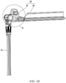
- Figs. 1A and 1B show a working device 100 in some embodiments.
- the working device 100 comprises a working portion 20, a long rod portion 10, and a grip portion 30.
- the long rod portion 10 is connected between the grip portion 30 and the working portion 20.
- the working portion 20 comprises a driving component 21 connected to the long rod portion 10, and a working component 22 protruding from the side of the driving component 21 facing away from the long rod portion 10 and driven by the driving component 21.
- the working portion 20 can be rotated relative to the long rod portion 10, so that a working range of the working portion 20 can be increased.
- the working device 100 is, for example, a trimmer or a cutting machine
- the working component 22 is a trimming component or a cutting component
- the long rod portion 10 is configured to enable, for example, the working device 100 to be used for trimming high branches, and the actual length of the long rod structure may be selectively set according to the height of an area to be worked.
- the long rod portion 10 is removable.
- a user may selectively remove the long rod portion 10 to directly engage the grip portion 30 with the working portion 20 when a target working area is not located at a high place.
- the dimension of the working component 22 has a dimension in a radial direction with respect to the rotation direction R that is greater than a corresponding dimension of the electric motor housing. That is to say, in some embodiments, the rotation angle of the working portion 20 relative to the long rod portion 10 is increased, and the length of the working component 22 is also increased, so that under the combined effect, the working area of the working portion 20 can be further increased.
- the process of rotating the working portion 20 relative to the long rod portion 10 may also be understood as the process of rotating the working portion 20 relative to the grip portion
- a rotation angle of the working portion 20 relative to the long rod portion 10 may also be understood as a rotation angle of the working portion 20 relative to the grip portion 30.
- the driving component 21 comprises an electric motor housing, the electric motor housing in turn comprises a housing body 211 and a connecting portion 212 that have inner cavities in communication with each other, and the electric motor housing has a variable angle relative to the grip portion 30.
- the connecting portion 212 is located on a rear side of the housing body 211.
- the term "rear side” may be understood as the side facing away from the working area.
- the electric motor 216 is located inside the housing body 211, and the connecting portion 212 is configured to be rotatably connected to the long rod portion 10, for example, to rotatably engage with the long rod portion 10 around the connecting portion 212.
- the long rod portion 10 comprises a long rod portion body 11 and a pair of clamping portions 12 protruding from the long rod portion body 11 and facing each other, and the connecting portion 212 is pivotally clamped between the pair of clamping portions 12. It may be understood that during rotation of the connecting portion 212 relative to the long rod portion 10, the position of the connecting portion 212 relative to the long rod portion 10 is roughly unchanged, while the housing body 211 on one side of the connecting portion 212 is driven to change an angle formed between the housing body and the long rod portion 10. The position of the working component 22 is also roughly fixed relative to the housing body 211, so that the working component can be rotated together with the housing body 211 relative to the long rod portion 10 to change the angle formed between the working component and the long rod portion 10.
- the fact that the position of the working component 22 is roughly fixed relative to the housing body 211 does not mean that the working component 22 must be completely fixedly connected to the housing body 211.
- the working component 22 may extend or retract relative to the housing body 211.
- the driving component 21 is provided with an air passage for providing air circulation to cool the electric motor 216
- the electric motor housing is provided with at least one air intake hole 212a, 212b and at least one exhaust hole 211a.
- the air intake hole 212a, 212b should be as far away from the working component 22 as possible, and thus, the air intake hole 212a, 212b is preferably formed in the connecting portion 212, in particular in a side face of the connecting portion 212 that faces away from the working component 22.
- the exhaust hole 211a should be provided as close as possible to an air discharge position of the electric motor 216, so that the exhaust hole 211a is formed in the housing body 211.
- the exhaust hole 211a is formed in a side face of the housing body 211 that is offset from the working component 22, that is, the exhaust hole 211a does not directly face the working component 22.
- the arrangement of the air intake hole 212a, 212b in the connecting portion 212 is a preferred arrangement, some problems are also caused.
- the connecting portion 212 always has a surface in close contact with the long rod portion body 11 during rotation of the electric motor housing relative to the long rod portion 10
- a situation may arise in which the air intake hole is in close contact with the long rod portion body 11 and is accordingly covered.
- at least two air intake holes are provided, which are arranged spaced apart from each other on the connecting portion 212 in the rotation direction R, and the at least two air intake holes are positioned such that at least one of the at least two air intake holes is exposed to the outside when the electric motor housing is located at any angular position relative to the long rod portion 10.
- Fig. 3 shows two air intake holes 212a, 212b in parts of the connecting portion 212, and the two air intake holes 212a, 212b are arranged spaced apart by approximately 90° in the rotation direction R.
- the air intake hole 212b is in close contact with the long rod portion body 11 and is accordingly covered, and the air intake hole 212a is exposed to the outside and accordingly can still introduce a cold airflow to the electric motor 216, ensuring normal cooling of the electric motor 216.
- the air intake hole 212a may be covered by the long rod portion body 11.
- the air intake hole 212a is covered, the air intake hole 212b must be exposed to the outside.
- the at least one air intake hole is in close contact with the long rod portion body 11 and is accordingly covered, and with such an arrangement, excessively concentrated arrangement of the air intake holes can be avoided.
- the working portion 20 is configured to have an angle about an axis (e.g., the rotation axis) relative to the long rod portion 10 that can vary by 90°, and preferably by 180°.
- the number and spacing angle of air intake holes 212a may be determined according to the rotation angle of the working portion 20 relative to the long rod portion 10. For example, in an embodiment in which the working portion can be rotated by 180° relative to the long rod portion, three or more air intake holes may be provided, which may be sequentially arranged spaced apart by 90° in the rotation direction.
- the air intake holes 212a, 212b may be configured as long holes.
- the air intake hole 212a may be a long hole extending between the two clamping portions 12, and the extending directions of the air intake holes 212a, 212b are substantially perpendicular to the extending directions of the working component 22.
- the air intake hole 212a may also have a special arrangement as shown in Fig. 4 .
- the air intake hole 212a is configured to provide a bent air path 213.
- the air path 213 has a bent structure in a plane (e.g., the plane shown in Fig. 4 ) perpendicular to the rotation axis of the connecting portion 212. It is preferable that the air intake path 213 has a bending angle of approximately 90°.
- the "rotation axis" is a virtual straight line that passes, for example, through the centre of a circle formed by an outer contour of the connecting portion 212 shown in Fig. 4 . Referring to Fig.
- a housing component at the connecting portion 212 may comprise, for example, a left-side housing component and a right-side housing component abutting together in the extending direction of the rotation axis, but the schematic view shown in Fig. 4 is the structure with the right-side housing component at the connecting portion 212 removed and the left-side housing component left.
- the air intake path 213 having a bending angle may be provided by providing a baffle plate.
- the connecting portion 212 comprises a baffle plate 214 arranged on an inner side of the air intake hole 212a and aligned with and spaced from the air intake hole 212a.
- the baffle plate 214 is designed to block an airflow so as to divert the airflow.
- a connecting plate 215 is connected between the portion of the electric motor housing defining the air intake hole 212a and the baffle plate 214.
- the baffle plate 214 has a size substantially the same as that of the air intake hole 212a.
- the present invention further has other preferred arrangements in terms of the configuration of the air passage for cooling the electric motor 216.
- the air discharge position of the electric motor 216 is arranged close to the top end thereof
- an air intake position of the electric motor 216 may be arranged, for example, close to the bottom end thereof
- an output end 216b of the electric motor 216 may be arranged close to the air intake position thereof.
- the output end 216b of the electric motor 216 may be connected to a working body of the working component 22 via a transmission mechanism (e.g., a gear transmission mechanism), for example.
- a partition plate 217 is provided inside the housing body 211.
- the partition plate 217 hermetically divides the housing body 211 into a first space (e.g., a space above the partition plate 217) and a second space (e.g., a space below the partition plate 217).
- An exhaust position 216a of the electric motor 216 is positioned in the first space; and the output end 216b and the air intake position of the electric motor 216 are positioned in the second space.
- Such an arrangement can enable the hot airflow that has passed through the electric motor 216 to be discharged only through the exhaust hole 211a without entering other areas in the electric motor housing, in particular without mixing with the cold airflow that will flow to the electric motor 216.
- Such an arrangement ensures the cooling efficiency for the electric motor 216, and also ensures that the performance of the output end 216b of the electric motor 216 and the working component 22 connected to the output end 216b is not affected by the hot airflow.
- the working device defines an airflow path from the at least one air intake hole 212a, 212b to the exhaust hole 211a of the electric motor housing, at least a part of the working component 22 is located in the airflow path, and preferably a gear transmission portion of the working component 22 is located in the airflow path.
- the partition plate 217 is a component separate from the electric motor housing, rather than a rib on the electric motor housing itself. Such an arrangement allows the partition plate 217 to be removed separately, enabling the housing body 211 to re-define an integral space when there is a special need.
- a driving component is provided with the air intake hole to allow air for cooling the electric motor to enter the interior of the driving component.
- the working portion can be rotated with respect to the grip portion so as to have an increased working angle, while the air intake hole in the driving component for introducing an airflow to cool the electric motor is arranged such that at least one air intake hole is always in communication with the outside when the working portion is in any angular position, so that the use efficiency of the electric motor can be ensured under any use condition.
- the present invention further ensures that the hot airflow that has passed through the electric motor can only be discharged from an exhaust hole without entering other areas in the electric motor housing, in particular without mixing with a cold airflow that will flow to the electric motor.
- Such an arrangement further ensures the cooling efficiency for the electric motor, and also ensures that the performance of an output end of the electric motor and a working component connected to the output end is not affected by the hot airflow.
Landscapes
- Life Sciences & Earth Sciences (AREA)
- Engineering & Computer Science (AREA)
- Biodiversity & Conservation Biology (AREA)
- Ecology (AREA)
- Forests & Forestry (AREA)
- Environmental Sciences (AREA)
- Mechanical Engineering (AREA)
- Power Engineering (AREA)
- Motor Or Generator Frames (AREA)
- Motor Or Generator Cooling System (AREA)
- Electrical Discharge Machining, Electrochemical Machining, And Combined Machining (AREA)
- Harvester Elements (AREA)
Abstract
Description
- The present invention relates to the field of handheld working tools, and in particular to a working device such as a trimmer or a cutting machine.
- At present, common working devices on the market, such as trimmers and cutting machines, have the problem of overheating of a motor during working. To cool the motor, an air intake hole and an exhaust hole that are in communication with the outside may be formed in a motor housing. The positions of the air intake hole and the exhaust hole are generally arranged simply. In some working devices, a working component may be rotatable relative to a handle, so that the part of the working component that engages with the handle may be covered by the handle. In this case, simply selecting the position of the air intake hole in the working component may result in the air intake hole being covered by the handle when the working component is rotated to a certain angle relative to the handle, thereby affecting the cooling effect on the motor and affecting the performance of the working device.
- In addition, in the common working devices on the market, the housing for accommodating the motor is usually an integral cavity; as a result, a hot airflow that has passed through the motor may flow in the housing. For example, the hot airflow may be mixed with a cold airflow that will flow to the motor, or may flow to an output end of the motor, resulting in a reduced cooling effect on the motor.
- Therefore, there is a need to provide a working device to at least partially solve the above problem.
- An objective of the present invention is to provide a working device such as a trimming device or a cutting device. In the working device of the present invention, a driving component is provided with an air intake hole to allow air for cooling an electric motor to enter the interior of the driving component. Further, a working portion can be rotated with respect to a grip portion so as to have an increased working angle, while the air intake hole in the driving component for introducing an airflow to cool the electric motor is arranged such that at least one air intake hole is always in communication with the outside when the working portion is in any angular position, so that the use efficiency of the electric motor can be ensured under any use condition.
- Further, in the working device of the present invention, a partition plate is provided in an electric motor housing, ensuring that the hot airflow that has passed through the electric motor can only be discharged from an exhaust hole without entering other areas in the electric motor housing, in particular without mixing with a cold airflow that will flow to the electric motor. Such an arrangement further ensures the cooling efficiency for the electric motor, and also ensures that the performance of an output end of the electric motor and a working component connected to the output end is not affected by the hot airflow.
- According to one aspect of the present invention, a working device is provided, comprising a working portion and a grip portion, the working portion comprising a driving component and a working component driven by the driving component, the driving component comprising an electric motor and an electric motor housing, wherein the electric motor housing comprises:
- a housing body, the electric motor being located in the housing body, and an exhaust hole being formed in the housing body; and
- a connecting portion located on a rear side of the housing body, wherein at least one air intake hole is formed in the connecting portion, and is in communication with an inner cavity of the housing body.
- In an embodiment, the electric motor housing has a variable angle relative to the grip portion, and the connecting portion comprises at least two air intake holes positioned such that at least one of the at least two air intake holes is exposed to the outside when the electric motor housing is at any angular position relative to the grip portion.
- In an embodiment, an extending direction of the at least one air intake hole is substantially perpendicular to an extending direction of the working component.
- In an embodiment, the air intake hole is configured to provide a bent air intake path, which preferably has a bending angle of approximately 90°.
- In an embodiment, the connecting portion comprises a baffle plate arranged on an inner side of the air intake hole and aligned with and spaced from the air intake hole, the baffle plate being designed to block an airflow so as to divert the airflow, and preferably having a size substantially the same as that of the air intake hole.
- In an embodiment, the working portion is configured to have an angle about an axis relative to the grip portion that can vary by 90°, and preferably by 180°; optionally, the connecting portion is provided with two or more air intake holes spaced apart in a circumferential direction of the axis, and preferably, two or three air intake holes respectively spaced apart by 90°; and optionally, the at least one air intake hole is positioned on the side of the connecting portion facing away from the working component.
- In an embodiment, the working device further comprises a long rod portion located between the electric motor housing and the grip portion, wherein the connecting portion is rotatably connected to the long rod portion.
- In an embodiment, the long rod portion comprises a long rod portion body and a pair of clamping portions protruding from the long rod portion body and facing each other, the connecting portion is pivotally clamped between the pair of clamping portions, and each of the air intake holes is an elongated hole extending between the pair of clamping portions.
- In an embodiment, the connecting portion always has a surface in close contact with the grip portion body during rotation of the electric motor housing relative to the grip portion, wherein at least one of the air intake holes is in close contact with the grip portion body and is accordingly covered when the electric motor housing is rotated to an extreme angular position relative to the grip portion.
- In an embodiment, a partition plate is provided inside the housing body and hermetically divides the housing body into a first space and a second space, the partition plate is positioned such that an exhaust position of the electric motor is located inside the first space, an output end of the electric motor is located inside the second space, the output end of the electric motor is preferably arranged close to an air intake end thereof, and the partition plate is preferably a component separate from the housing.
- In an embodiment, the exhaust hole is formed in a side face of the housing body that is offset from the working component.
- In an embodiment, the working component is a trimming component or a cutting component, and preferably the working component has a dimension in a radial direction with respect to the rotation direction that is greater than a corresponding dimension of the electric motor housing.
- In an embodiment, the working device defines an airflow path from the at least one air intake hole to the exhaust hole of the electric motor housing, at least a part of the working component is located in the airflow path, and preferably a gear transmission portion of the working component is located in the airflow path.
- In an embodiment, the working portion and the connecting portion are located on two opposite sides of the housing body.
- For a better understanding of the above and other obj ectives, features, advantages and functions of the present invention, reference may be made to the preferred embodiments shown in the accompanying drawings. In the accompanying drawings, the same reference numerals refer to the same components. It should be understood by those skilled in the art that the accompanying drawings are intended to illustrate schematically preferred embodiments of the present invention and do not impose any limitation to the scope of the present invention, and that the individual components in the figures are not drawn to scale.
-
Fig. 1A is a perspective view of a working device according to some preferred embodiments of the present invention; -
Fig. 1B is a perspective view in which a grip portion and part of a long rod structure inFig. 1A are cut off; -
Fig. 2 is a partial enlarged view of part A ofFig. 1B ; -
Fig. 3 is a separate schematic view of an electric motor inFig. 2 , showing two air intake holes in a connecting portion of an electric motor housing; -
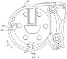
Fig. 4 is a partial schematic structural view of the connecting portion inFig. 3 with a right-side housing component at the connecting portion removed and a left-side housing component left, in order to clearly show the structural arrangement at the air intake hole; and -
Fig. 5 is a schematic view showing an internal structure of the electric motor inFig. 3 . -
- 100 Working device
- 10 Long rod portion
- 11 Long rod portion body
- 12 Clamping portion
- 20 Working portion
- 21 Driving component
- 22 Working component
- 211 Housing body
- 211a Exhaust hole
- 212 Connecting portion
- 212a, 212b Air intake hole
- 213 Air intake path
- 214 Baffle plate
- 215 Connecting plate
- 216 Electric motor
- 216a Exhaust position of the electric motor
- 216b Output end of the electric motor
- 217 Partition plate
- 30 Grip portion
- R Rotation direction
- Specific embodiments of the present invention are now described in detail with reference to the accompanying drawings. Only preferred embodiments according to the present invention are described here, and those skilled in the art would conceive of other ways of implementation of the present invention on the basis of the preferred embodiments, which also fall within the scope of the present invention.
-
Figs. 1A-5 show some preferred embodiments of a working device according to the present invention. First, it should be noted that directional and positional terms in the present invention should be construed as relative directions and positions, not absolute directions and positions. The directional and positional terms in the present invention can be explained with reference to exemplary structures shown inFigs. 1A-5 . For example, the rotation directions of a working portion, a driving component and a connecting portion of an electric motor housing relative to a long rod portion according to the present invention can be understood with reference to direction R inFigs. 2-4 ; and a rotation angle may be understood as an angle by which a housing body (or a working component) is rotated relative to the long rod portion (i.e., relative to a grip portion). -
Figs. 1A and1B show a workingdevice 100 in some embodiments. The workingdevice 100 comprises a workingportion 20, along rod portion 10, and a grip portion 30. Thelong rod portion 10 is connected between the grip portion 30 and the workingportion 20. The workingportion 20 comprises a drivingcomponent 21 connected to thelong rod portion 10, and a workingcomponent 22 protruding from the side of the drivingcomponent 21 facing away from thelong rod portion 10 and driven by the drivingcomponent 21. The workingportion 20 can be rotated relative to thelong rod portion 10, so that a working range of the workingportion 20 can be increased. - In some embodiments, the working
device 100 is, for example, a trimmer or a cutting machine, the workingcomponent 22 is a trimming component or a cutting component, thelong rod portion 10 is configured to enable, for example, the workingdevice 100 to be used for trimming high branches, and the actual length of the long rod structure may be selectively set according to the height of an area to be worked. In some embodiments, thelong rod portion 10 is removable. For example, a user may selectively remove thelong rod portion 10 to directly engage the grip portion 30 with the workingportion 20 when a target working area is not located at a high place. Preferably, the dimension of the workingcomponent 22 has a dimension in a radial direction with respect to the rotation direction R that is greater than a corresponding dimension of the electric motor housing. That is to say, in some embodiments, the rotation angle of the workingportion 20 relative to thelong rod portion 10 is increased, and the length of the workingcomponent 22 is also increased, so that under the combined effect, the working area of the workingportion 20 can be further increased. - It may be understood that since the relative positions of the
long rod portion 10 and the grip portion 30 are fixed during working, the process of rotating the workingportion 20 relative to thelong rod portion 10 may also be understood as the process of rotating the workingportion 20 relative to the grip portion, and a rotation angle of the workingportion 20 relative to thelong rod portion 10 may also be understood as a rotation angle of the workingportion 20 relative to the grip portion 30. - Referring to
Fig. 2 , the drivingcomponent 21 comprises an electric motor housing, the electric motor housing in turn comprises ahousing body 211 and a connectingportion 212 that have inner cavities in communication with each other, and the electric motor housing has a variable angle relative to the grip portion 30. The connectingportion 212 is located on a rear side of thehousing body 211. The term "rear side" may be understood as the side facing away from the working area. In some embodiments, theelectric motor 216 is located inside thehousing body 211, and the connectingportion 212 is configured to be rotatably connected to thelong rod portion 10, for example, to rotatably engage with thelong rod portion 10 around the connectingportion 212. - In some embodiments, the
long rod portion 10 comprises a longrod portion body 11 and a pair of clampingportions 12 protruding from the longrod portion body 11 and facing each other, and the connectingportion 212 is pivotally clamped between the pair of clampingportions 12. It may be understood that during rotation of the connectingportion 212 relative to thelong rod portion 10, the position of the connectingportion 212 relative to thelong rod portion 10 is roughly unchanged, while thehousing body 211 on one side of the connectingportion 212 is driven to change an angle formed between the housing body and thelong rod portion 10. The position of the workingcomponent 22 is also roughly fixed relative to thehousing body 211, so that the working component can be rotated together with thehousing body 211 relative to thelong rod portion 10 to change the angle formed between the working component and thelong rod portion 10. It should be noted that, the fact that the position of the workingcomponent 22 is roughly fixed relative to thehousing body 211 does not mean that the workingcomponent 22 must be completely fixedly connected to thehousing body 211. For example, the workingcomponent 22 may extend or retract relative to thehousing body 211. - In some embodiments, the driving
component 21 is provided with an air passage for providing air circulation to cool theelectric motor 216, and the electric motor housing is provided with at least oneair intake hole exhaust hole 211a. In order to prevent branches and leaves cut off by the workingcomponent 22, dust thereon, etc. from entering theair intake hole air intake hole component 22 as possible, and thus, theair intake hole portion 212, in particular in a side face of the connectingportion 212 that faces away from the workingcomponent 22. Theexhaust hole 211a should be provided as close as possible to an air discharge position of theelectric motor 216, so that theexhaust hole 211a is formed in thehousing body 211. In order to prevent the branches and leaves cut off by the workingcomponent 22, the dust thereon, etc. from entering theair intake hole exhaust hole 211a is formed in a side face of thehousing body 211 that is offset from the workingcomponent 22, that is, theexhaust hole 211a does not directly face the workingcomponent 22. - Although the arrangement of the
air intake hole portion 212 is a preferred arrangement, some problems are also caused. For example, if the connectingportion 212 always has a surface in close contact with the longrod portion body 11 during rotation of the electric motor housing relative to thelong rod portion 10, a situation may arise in which the air intake hole is in close contact with the longrod portion body 11 and is accordingly covered. In order to solve this problem, at least two air intake holes are provided, which are arranged spaced apart from each other on the connectingportion 212 in the rotation direction R, and the at least two air intake holes are positioned such that at least one of the at least two air intake holes is exposed to the outside when the electric motor housing is located at any angular position relative to thelong rod portion 10. -
Fig. 3 shows twoair intake holes portion 212, and the twoair intake holes Fig. 2 , theair intake hole 212b is in close contact with the longrod portion body 11 and is accordingly covered, and theair intake hole 212a is exposed to the outside and accordingly can still introduce a cold airflow to theelectric motor 216, ensuring normal cooling of theelectric motor 216. As the workingportion 20 continues to be rotated relative to thelong rod portion 10 so as to increase the angle therebetween, theair intake hole 212a may be covered by the longrod portion body 11. If theair intake hole 212a is covered, theair intake hole 212b must be exposed to the outside. Preferably, when the electric motor housing is rotated to an extreme angular position relative to thelong rod portion 10, the at least one air intake hole is in close contact with the longrod portion body 11 and is accordingly covered, and with such an arrangement, excessively concentrated arrangement of the air intake holes can be avoided. - In some embodiments, the working
portion 20 is configured to have an angle about an axis (e.g., the rotation axis) relative to thelong rod portion 10 that can vary by 90°, and preferably by 180°. The number and spacing angle ofair intake holes 212a may be determined according to the rotation angle of the workingportion 20 relative to thelong rod portion 10. For example, in an embodiment in which the working portion can be rotated by 180° relative to the long rod portion, three or more air intake holes may be provided, which may be sequentially arranged spaced apart by 90° in the rotation direction. - In order to increase the areas of the
air intake holes air intake hole 212a, theair intake holes air intake hole 212a may be a long hole extending between the two clampingportions 12, and the extending directions of theair intake holes component 22. To further avoid the introduction of foreign matter from theair intake hole 212a, theair intake hole 212a may also have a special arrangement as shown inFig. 4 . - Referring to
Fig. 4 , in some embodiments, theair intake hole 212a is configured to provide abent air path 213. For example, theair path 213 has a bent structure in a plane (e.g., the plane shown inFig. 4 ) perpendicular to the rotation axis of the connectingportion 212. It is preferable that theair intake path 213 has a bending angle of approximately 90°. The "rotation axis" is a virtual straight line that passes, for example, through the centre of a circle formed by an outer contour of the connectingportion 212 shown inFig. 4 . Referring toFig. 3 , a housing component at the connectingportion 212 may comprise, for example, a left-side housing component and a right-side housing component abutting together in the extending direction of the rotation axis, but the schematic view shown inFig. 4 is the structure with the right-side housing component at the connectingportion 212 removed and the left-side housing component left. - In some embodiments, the
air intake path 213 having a bending angle may be provided by providing a baffle plate. For example, the connectingportion 212 comprises abaffle plate 214 arranged on an inner side of theair intake hole 212a and aligned with and spaced from theair intake hole 212a. Thebaffle plate 214 is designed to block an airflow so as to divert the airflow. A connectingplate 215 is connected between the portion of the electric motor housing defining theair intake hole 212a and thebaffle plate 214. Preferably, thebaffle plate 214 has a size substantially the same as that of theair intake hole 212a. - The present invention further has other preferred arrangements in terms of the configuration of the air passage for cooling the
electric motor 216. For example, referring toFig. 5 , the air discharge position of theelectric motor 216 is arranged close to the top end thereof, an air intake position of theelectric motor 216 may be arranged, for example, close to the bottom end thereof, and anoutput end 216b of theelectric motor 216 may be arranged close to the air intake position thereof. Theoutput end 216b of theelectric motor 216 may be connected to a working body of the workingcomponent 22 via a transmission mechanism (e.g., a gear transmission mechanism), for example. Preferably, apartition plate 217 is provided inside thehousing body 211. Thepartition plate 217 hermetically divides thehousing body 211 into a first space (e.g., a space above the partition plate 217) and a second space (e.g., a space below the partition plate 217). Anexhaust position 216a of theelectric motor 216 is positioned in the first space; and theoutput end 216b and the air intake position of theelectric motor 216 are positioned in the second space. Such an arrangement can enable the hot airflow that has passed through theelectric motor 216 to be discharged only through theexhaust hole 211a without entering other areas in the electric motor housing, in particular without mixing with the cold airflow that will flow to theelectric motor 216. Such an arrangement ensures the cooling efficiency for theelectric motor 216, and also ensures that the performance of theoutput end 216b of theelectric motor 216 and the workingcomponent 22 connected to theoutput end 216b is not affected by the hot airflow. - The working device defines an airflow path from the at least one
air intake hole exhaust hole 211a of the electric motor housing, at least a part of the workingcomponent 22 is located in the airflow path, and preferably a gear transmission portion of the workingcomponent 22 is located in the airflow path. - Preferably, the
partition plate 217 is a component separate from the electric motor housing, rather than a rib on the electric motor housing itself. Such an arrangement allows thepartition plate 217 to be removed separately, enabling thehousing body 211 to re-define an integral space when there is a special need. - In the working device of the present invention, a driving component is provided with the air intake hole to allow air for cooling the electric motor to enter the interior of the driving component. Further, the working portion can be rotated with respect to the grip portion so as to have an increased working angle, while the air intake hole in the driving component for introducing an airflow to cool the electric motor is arranged such that at least one air intake hole is always in communication with the outside when the working portion is in any angular position, so that the use efficiency of the electric motor can be ensured under any use condition. The present invention further ensures that the hot airflow that has passed through the electric motor can only be discharged from an exhaust hole without entering other areas in the electric motor housing, in particular without mixing with a cold airflow that will flow to the electric motor. Such an arrangement further ensures the cooling efficiency for the electric motor, and also ensures that the performance of an output end of the electric motor and a working component connected to the output end is not affected by the hot airflow.
- The foregoing description of the multiple embodiments of the present invention is provided for descriptive purposes to a person of ordinary skill in the related art. It is not intended to exclude or limit the present invention to a single disclosed embodiment. As described above, various alternatives and modifications of the present invention will be apparent to those of ordinary skill in the art in light of the above teachings. Therefore, although some alternative embodiments have been described specifically, other embodiments will be apparent or relatively readily developed by those of ordinary skill in the art. The present invention aims to include all alternatives, modifications and variations of the present invention described herein, and the other embodiments that fall within the spirit and scope of the present invention described above.
Claims (14)
- Working device (100), comprising a working portion (20) and a grip portion (30), the working portion comprising a driving component (21) and a working component (22) driven by the driving component, the driving component comprising an electric motor (216) and an electric motor housing, characterized in that the electric motor housing comprises:a housing body (211), the electric motor being located in the housing body, and an exhaust hole (211a) being formed in the housing body; anda connecting portion (212) located on a rear side of the housing body, wherein at least one air intake hole (212a, 212b) is formed in the connecting portion, and is in communication with an inner cavity of the housing body (211).
- Working device according to Claim 1, characterized in that the electric motor housing has a variable angle relative to the grip portion, and the connecting portion comprises at least two air intake holes (212a, 212b) positioned such that at least one of the at least two air intake holes is exposed to the outside when the electric motor housing is at any angular position relative to the grip portion.
- Working device according to Claim 1, characterized in that an extending direction of the at least one air intake hole is substantially perpendicular to an extending direction of the working component (22).
- Working device according to Claim 1, characterized in that the air intake hole is configured to provide a bent air intake path (213), which preferably has a bending angle of approximately 90°.
- Working device according to Claim 1 or 2, characterized in that the connecting portion comprises a baffle plate (214) arranged on an inner side of the air intake hole and aligned with and spaced from the air intake hole, the baffle plate being designed to block an airflow so as to divert the airflow, and preferably having a size substantially the same as that of the air intake hole.
- Working device according to Claim 1, characterized in that the working portion is configured to have an angle about an axis relative to the grip portion that can vary by 90°, and preferably by 180°; optionally, the connecting portion is provided with two or more air intake holes spaced apart in a circumferential direction of the axis, and preferably, two or three air intake holes respectively spaced apart by 90°; and optionally, the at least one air intake hole is positioned on the side of the connecting portion facing away from the working component.
- Working device according to Claim 1, characterized in that the working device (100) further comprises a long rod portion (10) located between the electric motor housing and the grip portion, wherein the connecting portion (212) is rotatably connected to the long rod portion (10).
- Working device according to Claim 7, characterized in that the long rod portion (10) comprises a long rod portion body (11) and a pair of clamping portions (12) protruding from the long rod portion body and facing each other, the connecting portion (212) is pivotally clamped between the pair of clamping portions, and each of the air intake holes is an elongated hole extending between the pair of clamping portions.
- Working device according to any one of Claims 1-8, characterized in that the connecting portion always has a surface in close contact with the grip portion body during rotation of the electric motor housing relative to the grip portion, wherein at least one of the air intake holes is in close contact with the grip portion body and is accordingly covered when the electric motor housing is rotated to an extreme angular position relative to the grip portion.
- Working device according to any one of Claims 1-9, characterized in that a partition plate (216) is provided inside the housing body and hermetically divides the housing body into a first space and a second space, the partition plate is positioned such that an exhaust position (216a) of the electric motor is located inside the first space, an output end (216b) of the electric motor is located inside the second space, the output end of the electric motor is preferably arranged close to an air intake end thereof, and the partition plate is preferably a component separate from the housing.
- Working device according to any one of Claims 1-10, characterized in that the exhaust hole is formed in a side face of the housing body that is offset from the working component.
- Working device according to any one of Claims 1-11, characterized in that the working component (22) is a trimming component or a cutting component, and preferably the working component has a dimension in a radial direction with respect to the rotation direction that is greater than a corresponding dimension of the electric motor housing.
- Working device according to any one of Claims 1-12, characterized in that the working device defines an airflow path from the at least one air intake hole to the exhaust hole of the electric motor housing, at least a part of the working component is located in the airflow path, and preferably a gear transmission portion of the working component is located in the airflow path.
- Working device according to any one of Claims 1-13, characterized in that the working portion and the connecting portion are located on two opposite sides of the housing body.
Applications Claiming Priority (1)
| Application Number | Priority Date | Filing Date | Title |
|---|---|---|---|
| CN202210152257.3A CN116667584A (en) | 2022-02-18 | 2022-02-18 | operating device |
Publications (1)
| Publication Number | Publication Date |
|---|---|
| EP4230027A1 true EP4230027A1 (en) | 2023-08-23 |
Family
ID=85173968
Family Applications (1)
| Application Number | Title | Priority Date | Filing Date |
|---|---|---|---|
| EP23154930.4A Pending EP4230027A1 (en) | 2022-02-18 | 2023-02-03 | Working device |
Country Status (4)
| Country | Link |
|---|---|
| US (1) | US12151357B2 (en) |
| EP (1) | EP4230027A1 (en) |
| CN (1) | CN116667584A (en) |
| AU (1) | AU2023200257A1 (en) |
Citations (7)
| Publication number | Priority date | Publication date | Assignee | Title |
|---|---|---|---|---|
| JPH0519U (en) * | 1991-06-24 | 1993-01-08 | 石川島芝浦機械株式会社 | Electric mower |
| EP1738638A1 (en) * | 2005-06-30 | 2007-01-03 | Black & Decker, Inc. | Portable trimmer having rotatable power head |
| CN202444783U (en) * | 2011-10-10 | 2012-09-26 | 常州格力博工具有限公司 | Electric garden tool |
| EP2770814B1 (en) * | 2011-10-27 | 2020-02-19 | Husqvarna AB | Battery operated handheld power tool |
| WO2020173487A1 (en) * | 2019-02-27 | 2020-09-03 | 南京德朔实业有限公司 | Long pole power tool |
| EP3733347A1 (en) * | 2017-12-28 | 2020-11-04 | Koki Holdings Co., Ltd. | Power tool |
| CN215683383U (en) * | 2021-09-18 | 2022-02-01 | 格力博(江苏)股份有限公司 | Grass trimmer |
Family Cites Families (1)
| Publication number | Priority date | Publication date | Assignee | Title |
|---|---|---|---|---|
| DE102012007405B4 (en) * | 2012-04-16 | 2017-02-09 | Andreas Stihl Ag & Co. Kg | implement |
-
2022
- 2022-02-18 CN CN202210152257.3A patent/CN116667584A/en active Pending
-
2023
- 2023-01-18 AU AU2023200257A patent/AU2023200257A1/en active Pending
- 2023-02-03 EP EP23154930.4A patent/EP4230027A1/en active Pending
- 2023-02-10 US US18/108,294 patent/US12151357B2/en active Active
Patent Citations (7)
| Publication number | Priority date | Publication date | Assignee | Title |
|---|---|---|---|---|
| JPH0519U (en) * | 1991-06-24 | 1993-01-08 | 石川島芝浦機械株式会社 | Electric mower |
| EP1738638A1 (en) * | 2005-06-30 | 2007-01-03 | Black & Decker, Inc. | Portable trimmer having rotatable power head |
| CN202444783U (en) * | 2011-10-10 | 2012-09-26 | 常州格力博工具有限公司 | Electric garden tool |
| EP2770814B1 (en) * | 2011-10-27 | 2020-02-19 | Husqvarna AB | Battery operated handheld power tool |
| EP3733347A1 (en) * | 2017-12-28 | 2020-11-04 | Koki Holdings Co., Ltd. | Power tool |
| WO2020173487A1 (en) * | 2019-02-27 | 2020-09-03 | 南京德朔实业有限公司 | Long pole power tool |
| CN215683383U (en) * | 2021-09-18 | 2022-02-01 | 格力博(江苏)股份有限公司 | Grass trimmer |
Also Published As
| Publication number | Publication date |
|---|---|
| CN116667584A (en) | 2023-08-29 |
| US20230264336A1 (en) | 2023-08-24 |
| AU2023200257A1 (en) | 2023-09-07 |
| US12151357B2 (en) | 2024-11-26 |
Similar Documents
| Publication | Publication Date | Title |
|---|---|---|
| US11454250B2 (en) | Blower | |
| JP7316953B2 (en) | electric work machine | |
| CN101817176B (en) | The hand-held electric device that battery promotes | |
| US6155246A (en) | Power cutter | |
| US7646118B2 (en) | Portable power working machine | |
| JP5979364B2 (en) | Portable blower | |
| JP7254636B2 (en) | Blower | |
| US20080035361A1 (en) | Electric hand-held power tool | |
| EP3449790B1 (en) | Motor module and vacuum cleaner | |
| CN115842435A (en) | Hand-held electric tool and motor assembly for electric tool | |
| JP2003200364A (en) | Hand-held machine tool with air inlet or air outlet in casing | |
| US12151357B2 (en) | Working device | |
| US20240300084A1 (en) | Electric Working Machine | |
| US20240298580A1 (en) | Electric Working Machine | |
| WO2016151100A1 (en) | Visible motor saw head layout | |
| JP7256762B2 (en) | Electric working machine and its assembly method | |
| US20250063992A1 (en) | Working machine and vibration damping member | |
| JP2004066439A (en) | Power tool | |
| CN119098629A (en) | Cutting saw | |
| JP4782514B2 (en) | Electric working machine | |
| JP2004261053A (en) | Hand-held pruning machine | |
| US20250063991A1 (en) | Working machine | |
| WO2017064901A1 (en) | Electric tool | |
| BR102019027214A2 (en) | CONSTRUCTIVE PROVISION APPLIED IN ELECTRICAL TOOLS | |
| JP2002331473A (en) | Electric tool |
Legal Events
| Date | Code | Title | Description |
|---|---|---|---|
| PUAI | Public reference made under article 153(3) epc to a published international application that has entered the european phase |
Free format text: ORIGINAL CODE: 0009012 |
|
| STAA | Information on the status of an ep patent application or granted ep patent |
Free format text: STATUS: THE APPLICATION HAS BEEN PUBLISHED |
|
| AK | Designated contracting states |
Kind code of ref document: A1 Designated state(s): AL AT BE BG CH CY CZ DE DK EE ES FI FR GB GR HR HU IE IS IT LI LT LU LV MC ME MK MT NL NO PL PT RO RS SE SI SK SM TR |
|
| STAA | Information on the status of an ep patent application or granted ep patent |
Free format text: STATUS: REQUEST FOR EXAMINATION WAS MADE |
|
| 17P | Request for examination filed |
Effective date: 20240221 |
|
| RBV | Designated contracting states (corrected) |
Designated state(s): AL AT BE BG CH CY CZ DE DK EE ES FI FR GB GR HR HU IE IS IT LI LT LU LV MC ME MK MT NL NO PL PT RO RS SE SI SK SM TR |