WO2017064901A1 - Electric tool - Google Patents
Electric tool Download PDFInfo
- Publication number
- WO2017064901A1 WO2017064901A1 PCT/JP2016/072650 JP2016072650W WO2017064901A1 WO 2017064901 A1 WO2017064901 A1 WO 2017064901A1 JP 2016072650 W JP2016072650 W JP 2016072650W WO 2017064901 A1 WO2017064901 A1 WO 2017064901A1
- Authority
- WO
- WIPO (PCT)
- Prior art keywords
- cover
- tool
- intake
- output shaft
- semicircular
- Prior art date
Links
Images


Classifications
-
- B—PERFORMING OPERATIONS; TRANSPORTING
- B23—MACHINE TOOLS; METAL-WORKING NOT OTHERWISE PROVIDED FOR
- B23D—PLANING; SLOTTING; SHEARING; BROACHING; SAWING; FILING; SCRAPING; LIKE OPERATIONS FOR WORKING METAL BY REMOVING MATERIAL, NOT OTHERWISE PROVIDED FOR
- B23D57/00—Sawing machines or sawing devices not covered by one of the preceding groups B23D45/00 - B23D55/00
-
- B—PERFORMING OPERATIONS; TRANSPORTING
- B23—MACHINE TOOLS; METAL-WORKING NOT OTHERWISE PROVIDED FOR
- B23Q—DETAILS, COMPONENTS, OR ACCESSORIES FOR MACHINE TOOLS, e.g. ARRANGEMENTS FOR COPYING OR CONTROLLING; MACHINE TOOLS IN GENERAL CHARACTERISED BY THE CONSTRUCTION OF PARTICULAR DETAILS OR COMPONENTS; COMBINATIONS OR ASSOCIATIONS OF METAL-WORKING MACHINES, NOT DIRECTED TO A PARTICULAR RESULT
- B23Q11/00—Accessories fitted to machine tools for keeping tools or parts of the machine in good working condition or for cooling work; Safety devices specially combined with or arranged in, or specially adapted for use in connection with, machine tools
- B23Q11/08—Protective coverings for parts of machine tools; Splash guards
-
- B—PERFORMING OPERATIONS; TRANSPORTING
- B27—WORKING OR PRESERVING WOOD OR SIMILAR MATERIAL; NAILING OR STAPLING MACHINES IN GENERAL
- B27B—SAWS FOR WOOD OR SIMILAR MATERIAL; COMPONENTS OR ACCESSORIES THEREFOR
- B27B19/00—Other reciprocating saws with power drive; Fret-saws
- B27B19/02—Saws with a power- driven blade chucked at both ends or at one end only, e.g. jig saws, scroll saws
- B27B19/09—Saws with a power- driven blade chucked at both ends or at one end only, e.g. jig saws, scroll saws portable
-
- B—PERFORMING OPERATIONS; TRANSPORTING
- B27—WORKING OR PRESERVING WOOD OR SIMILAR MATERIAL; NAILING OR STAPLING MACHINES IN GENERAL
- B27B—SAWS FOR WOOD OR SIMILAR MATERIAL; COMPONENTS OR ACCESSORIES THEREFOR
- B27B23/00—Other cutting of wood by non-rotary toothed tools; Tools therefor
-
- B—PERFORMING OPERATIONS; TRANSPORTING
- B27—WORKING OR PRESERVING WOOD OR SIMILAR MATERIAL; NAILING OR STAPLING MACHINES IN GENERAL
- B27G—ACCESSORY MACHINES OR APPARATUS FOR WORKING WOOD OR SIMILAR MATERIALS; TOOLS FOR WORKING WOOD OR SIMILAR MATERIALS; SAFETY DEVICES FOR WOOD WORKING MACHINES OR TOOLS
- B27G3/00—Arrangements for removing bark-zones, chips, waste, or dust, specially designed for use in connection with wood-working machine or in wood-working plants
Definitions
- the present invention relates to an electric tool for cutting a workpiece by reciprocating a saw blade member attached to an output shaft within a predetermined angle range.
- An electric tool called a multi-tool is known.
- This electric tool incorporates a motor as a drive source.
- the output shaft is driven to reciprocate at high speed in a small angle range.
- a sanding pad for grinding a machined surface of wood is attached to the output shaft.
- a discharge connecting part is attached to the discharge hood in order to remove generated dust.
- a saw blade member called a cut or round saw may be attached to the output shaft instead of a sanding pad.
- the workpiece is cut by the reciprocating motion of the blade edge of the saw blade member.
- the above-described electric tool may be used when cutting the house ceiling.
- the cutting powder generated by the cutting falls from the overhead to the operator. Therefore, it is difficult for the operator to perform the cutting work. Therefore, there has been a need for an electric tool that is easy to perform cutting work by suppressing the cutting powder generated by cutting from falling on the operator.
- the power tool reciprocates the saw blade member at a predetermined angle to cut the workpiece.
- the electric tool includes a tool body, an output shaft protruding from the tool body, and a motor provided in the tool body for reciprocating a saw blade member attached to the output shaft at a predetermined angle to cut a workpiece.
- the electric tool is further provided with a mounting portion provided at the lower end of the output shaft to which the saw blade member is attached, and a first portion that is attached to the tool body and covers the outer periphery of the mounting portion and opens the front side that is the blade tip side of the saw blade member. Has a cover.
- the first cover has a lower wall part that is semicircular in plan view and faces the attachment part below the attachment part, and an upper wall part that is semicircular in plan view and faces the lower wall part above the attachment part.
- the first cover further includes a peripheral wall portion that connects the ends of the arcs of the lower wall portion and the upper wall portion and that faces the handle side of the tool body.
- the peripheral wall portion is arranged facing the handle side of the tool body, the cutting powder generated by cutting is blocked by the peripheral wall portion even if it comes toward the handle side. Thereby, it is suppressed that the cutting powder produced by cutting falls on an operator, and cutting workability
- the first cover is supported by the tool body so as to be displaceable in the arc direction.
- a plurality of intake openings communicating with the inside and outside of the first cover are arranged in an arc direction, and the first cover is displaced to replace one of the plurality of intake openings.
- the other one is located at a location corresponding to the intake duct and connected to the intake duct.
- the blade edge of the saw blade member can be rotationally displaced with respect to the tool body, and the first cover can also be rotationally displaced accordingly. Since another one of the intake openings is located at a location corresponding to the intake duct and the intake duct can be connected to the other one, the intake duct can be easily connected to the first cover. Therefore, even when the blade edge of the saw blade member is rotationally displaced, the cutting powder can be sucked satisfactorily and cutting workability can be improved.
- the intake duct is supported by the housing of the tool body. Therefore, it is possible to improve the cutting workability by stabilizing the intake duct that sucks the cutting powder.
- the upper wall of the first cover includes an intake opening. Therefore, the connection position of the intake duct can be set to the upper side with respect to the first cover. When the intake duct is positioned above the first cover, the vertical length of the intake duct can be shortened. Therefore, the configuration of the power tool can be made compact, and the operability of the power tool can be improved.
- the second cover has a cylindrical shape that is attached to the front side of the first cover and extends in an opening direction from the attachment portion toward the blade edge of the saw blade member. Therefore, the second cover can cover the periphery of the blade edge of the saw blade member. Thus, the cutting powder can be sucked while suppressing the scattering of the cutting powder generated from the blade edge of the saw blade member.
- the second cover is configured to be extendable and contractible in the direction from the blade edge of the saw blade member to the mounting portion. Therefore, the second cover can cover the saw blade member close to or beyond the blade edge. For example, when the blade edge of the saw blade member is positioned in the vicinity of the workpiece, or when inserted into the workpiece, the second cover can hit the workpiece and shrink. Therefore, the saw blade member can cut the workpiece without being obstructed by the second cover. Therefore, many parts of the saw blade member can be covered with the second cover.
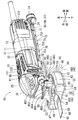
- FIG. 3 is a cross-sectional view of the multitool taken along line III-III in FIG. 1.
- FIG. 4 is a cross-sectional view of the multitool taken along line IV-IV in FIG. 1.
- It is a perspective view of the multitool from which the member cover is removed.
- It is a perspective view of a shaft cover.
- It is a partial perspective view of the multi-tool with the shaft cover removed and the saw blade member attached.
- It is a left view of the multi tool of FIG. It is a top view of the multi tool which rotated the dust collecting cover to the left side.
- It is the perspective view of the multi tool which replaced
- the power tool is, for example, a multi-tool 10.
- the multitool 10 is used for cutting a gypsum board, used for peeling a P tile, or used for grinding wood.
- a household AC power source is used as the power source of the multitool 10.
- the multi-tool 10 has an output shaft 31 that protrudes downward from the tool body 11, and a tool holder 32 is provided at the lower end of the output shaft 31.
- the tool holder (attachment portion) 32 holds a cut saw (saw blade member) 90 as a tip tool.
- the multi-tool 10 reciprocates the cutting edge 95 of the cut saw 90 at a high speed within a minute angle range when cutting the workpiece.
- the cut saw 90 generally includes a mounting portion 91, a long plate portion 93, and a cutting edge 95.
- the attachment portion 91 is attached to the tool holder 32.
- the long plate portion 93 sets the length between the attachment portion 91 and the blade edge 95.
- the long plate portion 93 is a plate shape that extends from the attachment portion 91 to the cutting edge 95 and forms a rectangular shape in a top view.
- the blade edge 95 is provided with a saw blade.
- the blade is set to extend in a direction orthogonal to the direction in which the long plate portion 93 extends.
- the blade edge 95 is straight.
- the blade edge 95 is located at the tip of the long plate portion 93 and can face the cutting material.
- the multitool 10 is, for example, TMA009BIM manufactured by Makita Corporation.
- the multi-tool 10 has a cut-and-saw 90 attached to a tool holder (attachment portion) 32.
- the tool holder 32 reciprocates together with the output shaft 31 to reciprocate the cutting edge 95 of the cut saw 90.
- the output shaft 31 reciprocates in a minute angle range such as 3.2 degrees.
- the output shaft 31 reciprocates at a short cycle or reciprocates at a high speed. Therefore, the blade edge 95 reciprocates so as to vibrate.
- a saw blade member is detachably attached to the multitool 10.
- the saw blade member is, for example, a cut saw 90, a round saw 90A having an arcuate cutting edge 95A shown in FIG. 12, a scraper used for paint peeling work, a sanding pad used for grinding work or polishing work, and the like.
- the multitool 10 generally includes a tool body 11 and a dust suction device 40.
- the tool main body 11 includes a motor unit 21 and a mechanical unit 25.
- the motor unit 21 includes a motor 210 and a cooling fan 225 built in the motor housing 22.
- the motor housing 22 is substantially cylindrical. For this reason, the outer periphery of the motor housing 22 can be easily gripped by hand, and the motor housing 22 functions as a handle portion (handle, grip) 17 of the multitool 10.
- An operation switch 151 is provided on the front upper side of the motor housing 22. When the operation switch 151 is slid forward, an ON signal is input to the controller 155 inside the motor housing 22. A speed signal is input to the controller 155 from a speed dial 152 provided at the rear of the tool body 11. The controller 155 controls the rotational drive of the motor 210 based on the speed signal and the ON signal.
- the motor 210 rotates the motor shaft 211 around the axis.
- the motor shaft 211 is rotatably supported by the motor housing 22 by a rear bearing 221 and a front bearing 222.
- the motor 210 includes a stator 212 supported by the motor housing 22 and a rotor 213 supported by the motor shaft 211.
- a coil 214 is wound around the rotor 213. Electricity flows through the coil 214 through the commutator 215. The electricity that flows is controlled by the controller 155.
- the motor 210 to which electricity is passed drives the motor shaft 211 to rotate.
- the rotating motor shaft 211 inputs a rotational driving force to the mechanical unit 25 while rotating the cooling fan 225.
- a cooling fan 225 is attached to the front portion of the motor shaft 211.
- the cooling fan 225 is a centrifugal fan that rotates integrally with the motor shaft 211.
- the cooling air generated by the cooling fan 225 cools the motor 210 and the controller 155.
- an air inlet 231 is provided at the rear part of the motor housing 22.
- An exhaust port 232 is provided in the front portion of the motor housing 22.
- the intake port 231 and the exhaust port 232 communicate with the inside and outside of the motor housing 22 so as to allow ventilation.
- a female portion 24 for locking the locking claw portion 87 of the duct holder 85 is provided at the lower portion of the air inlet 231.
- the mechanical unit 25 has a mechanical unit built in the mechanical housing 26 as shown in FIG.
- the mechanical unit has an eccentric shaft portion 271 attached to the front end of the motor shaft 211.
- the eccentric shaft portion 271 is located on the front side of the front bearing 222.
- the eccentric shaft portion 271 rotates around the position deviated from the center of the motor shaft 211 by receiving the rotational drive of the motor shaft 211 (eccentric motion).
- a sphere bearing 273 is attached to the outer periphery of the eccentric shaft portion 271. As shown in FIG. 4, the sphere bearing 273 is a rolling bearing in which the outer ring has a spherical surface.
- the eccentric motion of the eccentric shaft portion 271 is transmitted to the swing arm 28 via the sphere bearing 273.
- the swing arm 28 is integrally attached to the output shaft 31.
- the swing arm 28 includes a swing receiving portion 281 to which the sphere bearing 273 hits, and a swing fulcrum portion 283 attached integrally to the output shaft 31.
- the swing receiving portion 281 is provided with an appropriate clearance between the sphere bearing 273 in the vertical direction.
- the swing receiving portion 281 is in close contact with the sphere bearing 273 in the left-right direction. For this reason, the swing receiving portion 281 follows the eccentric motion of the eccentric shaft portion 271 via the sphere bearing 273 while escaping the eccentric motion of the eccentric shaft portion 271 in the vertical direction.
- the swing receiving portion 281 reciprocates left and right with the swing fulcrum portion 283 as a fulcrum, and the swing fulcrum portion 283 reciprocates within a predetermined angle range. Since the swing fulcrum part 283 is integrated with the output shaft 31, the output shaft 31 is reciprocally rotated by reciprocating rotation.
- the output shaft 31 is supported by the mechanical housing 26 via the upper bearing 311 and the lower bearing 312.
- the upper bearing 311 is a needle bearing
- the lower bearing 312 is a ball bearing.
- the output shaft 31 extends in the vertical direction perpendicular to the motor shaft 211.
- a lower portion of the output shaft 31 protrudes outside the mechanical housing 26, and a tool holder 32 is attached to the lower end of the output shaft 31.
- a cut-and-sew 90 is attached to the output shaft 31 via the tool holder 32.
- the cutting edge 95 of the cut-and-sew 90 can reciprocate at a minute angle to cut the workpiece.
- a lower portion of the outer periphery of the mechanical housing 26 is formed as a cylindrical fastened portion 30 as shown in FIG.
- the fastening portion 48 (see FIG. 6) of the shaft cover 42 is fastened to the fastened portion 30.
- the dust suction device 40 roughly includes a dust suction cover 41 and an intake duct 71.
- the dust collection cover 41 covers the outer periphery of the output shaft 31 and the outer periphery of the cut saw 90.
- the dust collection cover 41 includes a shaft cover 42 (first cover) and a member cover 60 (second cover).
- the shaft cover 42 mainly covers the output shaft 31 and the attachment portion 91 of the cut-and-sew 90.
- the member cover 60 mainly covers the outer periphery of the cut saw 90.
- the shaft cover 42 includes a cover main body 43 and a fastening portion 48.
- the cover body 43 has an internal space structure that is semicircular when viewed from above.
- the cover body 43 is set so as to cover the outer half of the output shaft 31.
- the shaft cover 42 covers the outer periphery of the tool holder 32 by opening the front side that becomes the cutting edge 95 of the cut-and-saw 90.
- the shaft cover 42 includes a semicircular upper wall (upper wall portion) 44, a semicircular lower wall (lower wall portion) 45, and an arc peripheral wall (peripheral wall portion) 46.
- the semicircular upper wall 44 is semicircular in plan view.
- the semicircular lower wall 45 also has a semicircular shape in plan view that forms a pair with the semicircular upper wall 44.
- An arc peripheral wall 46 connects the arc end edge 442 of the semicircular upper wall 44 and the arc end edge 452 of the semicircular lower wall 45.
- the cover main body 43 of the shaft cover 42 is opened only at the front side, and is closed by the semicircular upper wall 44, the semicircular lower wall 45, and the circular arc peripheral wall 46 in the vertical and horizontal directions.
- the semicircular upper wall 44 has an upper surface 441
- the semicircular lower wall 45 has a lower surface 451
- the circular arc peripheral wall 46 has a side surface 461.
- An opening 47 is provided on the front surface of the cover main body 43.
- the opening 47 is a rectangle that extends long in the left-right direction. The opening 47 is opened so that the cut saw 90 can protrude forward.
- the cover main body 43 is formed integrally with the base body 481 of the fastening portion 48 using resin as a material.
- the cover main body 43 is formed by integrally combining an upper member 50 and a lower member 55 that are divided vertically. As shown in FIGS. 3 and 6, this uniting is performed by fitting the rear end side fitting portion 57 and the overlapping portion 58 provided on the lower member 55 to the upper member 50.
- the semicircular upper wall 44 is provided with a fastening portion 48.
- the fastening portion 48 includes a base body 481 that is integrated with the semicircular upper wall 44, a rotating portion 483 that is separated from at least one end of the semicircular upper wall 44, and a clamp screw 487 that fastens them.
- One end of the base body 481 is provided with a screw hole 482 through which the clamp screw 487 can be inserted.
- the base body 481 and the rotating portion 483 are formed in an integral substantially cylindrical shape that is continuous with each other. As shown in FIG. 5, the base body 481 and the rotating portion 483 have a shape that can be in close contact with the outer periphery of the fastened portion 30.
- a hole 484 through which the clamp screw 487 can be inserted is provided at the other end of the rotating portion 483.
- the clamp screw 487 is screwed into a nut 486 held in the hole 484.
- the nut 486 is held in the hole 484 so as not to rotate.
- a projecting hole 49 for projecting the output shaft 31 is provided inside the cover body 43 below the fastening portion 48.
- a tool holder 32 is provided at the lower end of the output shaft 31 protruding into the cover body 43 through the protruding hole 49. Therefore, when the shaft cover 42 is attached to the tool body 11, the semicircular upper wall 44 is disposed on the upper side with respect to the tool holder 32, and the semicircular lower wall 45 is on the lower side with respect to the tool holder 32. Will be placed.
- the semicircular upper wall 44 and the semicircular lower wall 45 are arranged to face each other so as to sandwich the tool holder 32 in the vertical direction.
- the circular arc peripheral wall 46 is arranged toward the handle side of the tool body 11.
- the shaft cover 42 is attached to the tool body 11 with the circular arc circumferential wall 46 facing the handle portion 17 side.
- the arcs of the semicircular upper wall 44, the semicircular lower wall 45, and the circular arc peripheral wall 46 are arcs around the fastening portion 48 (output shaft 31) fastened to the fastened portion 30. Therefore, when the shaft cover 42 (dust collection cover 41) is displaced in the arc direction with respect to the mechanical housing 26 and the clamp screw 487 is tightened again, the fastening portion 48 is fastened to the fastened portion 30 and the dust suction cover 41 is connected to the mechanical housing. 26 will be supported.
- the semicircular upper wall 44 is provided with seven intake holes (intake openings) 51.
- the intake hole 51 communicates the inside and the outside of the cover main body 43 (shaft cover 42) so as to open the upper surface.
- the seven intake holes 51 are arranged at equal intervals in the circumferential direction (arc direction) on the semicircular upper wall 44 forming the upper surface 441.
- Each of the seven intake holes 51 passes through the semicircular upper wall 44 in a substantially rectangular shape when viewed from above.
- the central intake hole 52 disposed in the center is located at the center of the arc of the semicircular upper wall 44.
- An intake port portion 82 of an intake duct 71 is selectively inserted and connected to one of the seven intake holes 51.
- the upper surface 441 faces the mechanical housing 26.
- the rotation direction of the dust cover 41 around the output shaft 31 coincides with the direction in which the circular arc peripheral wall 46 extends, and also coincides with the rotation direction of the output shaft 31.
- the intake hole 51 includes a central intake hole 52, three intake holes 51 arranged on the left side of the central intake hole 52, and three intake holes 51 arranged on the right side of the central intake hole 52.
- the seven intake holes 51 are arranged in the rotation direction of the output shaft 31. Therefore, when the shaft cover 42 is rotationally displaced about the output shaft 31 and supported by the tool body 11, the intake duct 71 can be connected to any one of the seven intake holes 51. For example, as shown in FIG. 10, when the dust suction cover 41 is rotated to the left side, the intake hole 51 adjacent to the left of the central intake hole 52 is positioned directly below the tool body 11.
- the intake duct 71 can be connected to the intake hole 51 on the left side.
- the opening of the intake hole 51 is set to a size that allows the intake port portion 82 of the intake duct 71 to be fitted without a gap. It is preferable to insert the intake port portion 82 of the intake duct 71 into the intake hole 51 located directly below the tool body 11.
- the semicircular upper wall 44 is provided with locking bosses 53 protruding upward one by one in the left-right symmetrical position with the output shaft 31 interposed therebetween.
- the semicircular lower wall 45 is also provided with locking bosses 54 projecting downward at left and right symmetrical positions with the output shaft 31 in between.
- the locking bosses 53 and 54 are locked with the locking holes 66 of the member cover 60.
- the locking bosses 53 and 54 are provided at locations near the opening 47 in the semicircular upper wall 44 and the semicircular lower wall 45.
- the member cover 60 is attached to the front side of the opening 47 by locking the locking holes 66 in the locking bosses 53 and 54.
- the member cover (second cover) 60 covers the periphery of the cut saw 90 except for or including the blade edge 95.
- the member cover 60 is attached to the front side of the shaft cover 42 as shown in FIGS.
- the member cover 60 has a rectangular tube shape surrounding the top, bottom, left and right while communicating in the front-rear direction.
- the member cover 60 has a cylindrical shape that opens and extends in a direction from the tool holder 32 toward the blade edge 95 of the cut saw 90.
- a rear opening 61 and a front opening 62 are set at the rear and front of the member cover 60.
- the rear opening 61 is set to a square shape that matches the shape of the opening 47 of the shaft cover 42.
- the front opening 62 is set so as to protrude slightly forward from the cutting edge 95 of the cut saw 90.
- the member cover 60 is formed of a soft resin that can be easily elastically deformed when a force is applied. That is, the member cover 60 is formed to be extendable and contractable in the direction from the cutting edge 95 of the cut-and-saw 90 toward the attachment portion 91.
- the member cover 60 has a bellows portion 63 and an attachment portion 64.
- the bellows portion 63 has a bellows shape like a flexible tube used in, for example, electric piping. Specifically, the bellows portion 63 is formed so that the uneven shape is continuously repeated. The uneven shape is formed so as to extend in the left-right direction with respect to the upper and lower surfaces, and is formed so as to extend in the up-down direction with respect to the left and right surfaces.
- the bellows portion 63 can be expanded and contracted in the forward direction from the output shaft 31 toward the blade edge 95. That is, the length between the openings 61 and 62 can be relatively deformed in the expansion / contraction direction.
- the member cover 60 that is relatively deformed in the expansion / contraction direction is restored to its original state by elastic recovery due to its own material properties.
- the attachment portion 64 is set in a range on the rear side of the bellows portion 63.
- the attachment portion 64 is formed by providing a locking hole 66 in the smooth end portion 65.
- the smooth end portion 65 has a smooth flat plate shape.
- the smooth end 65 is provided with two locking holes 66 at the top and bottom.
- the locking hole 66 is a female hole into which the locking bosses 53 and 54 (see FIG. 2) are fitted.
- the locking hole 66 is provided in the smooth end portion 65 at a position corresponding to the locking bosses 53 and 54.
- the front edge 68 of the member cover 60 is an edge that contacts the workpiece. As the cut saw 90 is cut, the front edge 68 of the member cover 60 is pressed against the workpiece, and the bellows portion 63 contracts in the front-rear direction as shown in FIGS. When the front end edge 68 of the member cover 60 is separated from the workpiece, the member cover 60 returns to its original state due to elastic recovery.
- the resin for forming the member cover 60 is preferably a permeable resin such as a transparent resin so that the cut saw 90 inside the member cover 60 can be seen. Further, the member cover 60 may be formed so as to make the blade edge 95 of the cut saw 90 visible from the outside by making a cut or the like corresponding to the location where the cut saw 90 exists.
- the intake duct 71 is arranged directly below the tool body 11 and is held by the tool body 11.
- the intake duct 71 includes a duct main body 72 disposed immediately below the tool main body 11, and a duct holder 85 that integrates the duct main body 72 with the motor housing 22.
- the duct body 72 is formed in a cylindrical shape extending in the front-rear direction.
- the intake duct 71 is supported on the motor housing 22 by a duct holder 85.
- the duct body 72 can be functionally divided into a rear duct portion 73 on the rear side and a front duct portion 80 on the front side.
- the duct main body 72 is molded by blow molding using resin as a material, like the cover main body 43.
- the rear duct portion 73 and the front duct portion 80 are connected to each other to form a duct body 72, and both the rear duct portion 73 and the front duct portion 80 extend in the front-rear direction.
- the rear duct portion 73 is disposed immediately below the handle portion 17 until it contacts the motor housing 22.
- An exhaust port part 74 is provided at the rear end of the rear duct part 73.
- the lower surface of the rear duct portion 73 is provided with a concavo-convex shape by setting three concave portions 751, 752, and 753 at appropriate intervals.
- the three concave portions 751, 752, and 753 are shaped such that fingers of the hand enter when the user grips the handle portion 17 with a hand.
- the rear duct portion 73 is provided with a step portion 76 set in the vertical direction between the first concave portion 751 and the second concave portion 752 from the front.
- the stepped portion 76 is set corresponding to the outer peripheral design of the motor housing 22.
- a holder concave portion 77 is provided at the rear portion of the rear duct portion 73.
- the holder recess 77 is recessed one step upward on the front side of the exhaust port portion 74.
- the holder main body 86 of the duct holder 85 is fitted into the holder recess 77.
- the duct holder 85 includes a holder main body 86 that holds the duct main body 72, and a locking claw portion 87 that locks the holder main body 86 with the motor housing 22.
- the holder main body 86 has a curved shape so as to fit into the holder concave portion 77 of the duct main body 72.
- the locking claw portions 87 are set at both ends of the holder main body 86 and include claws that are locked to the female portion 24 at the lower part of the air inlet 231.
- the duct holder 85 is engaged with the female recess 24 of the tool main body 11 by the engaging claw 87 while being fitted in the holder recess 77, and supports the duct main body 72 integrally with the tool main body 11.
- the front duct portion 80 is disposed immediately below the position straddling the handle portion 17 and the mechanical portion 25.
- the front duct portion 80 is connected to the rear duct portion 73 via the first bent portion 79.
- the first bent portion 79 has a shape that bends the front duct portion 80 downward from the rear duct portion 73 in a step shape. For this reason, the front duct portion 80 is disposed away from the tool body 11 by a space S downward.
- An intake port portion 82 is provided at the front end of the front duct portion 80 via a second bent portion 81.
- the second bent portion 81 has a shape in which the front end portion of the front duct portion 80 is bent downward so that the air inlet portion 82 faces downward.
- the intake port portion 82 turned downward is inserted into the intake hole 51 of the shaft cover 42.
- the intake port portion 82 can be inserted into any of the seven intake holes 51 by loosening the clamp screw 487 and rotating the dust cover 41 in the circumferential direction.
- the intake duct 71 is disposed directly below the tool body 11. For this reason, the intake hole 51 into which the intake port portion 82 is inserted becomes the intake hole 51 positioned directly below the tool body 11.
- the air inlet portion 82 is inserted into the central air inlet hole 52 directly below the tool body 11.
- the intake port portion 82 is inserted into the intake hole 51 adjacent to the left of the central intake hole 52 directly below the tool body 11.
- the front duct part 80 when the extension part 83 of the front duct part 80 is pushed upward from the lower side, the front duct part 80 is displaced upward so as to narrow the space S with the tool body 11.
- the intake port portion 82 of the front duct portion 80 inserted into the intake hole 51 is displaced so as to come out of the intake hole 51.
- the clamp screw 487 can be loosened to rotate the dust suction cover 41 in the circumferential direction.
- the direction of the dust-absorbing cover 41 is generally adjusted to the protruding direction of the cut saw 90 held by the tool holder 32.
- the shaft cover 42 includes a semicircular upper wall 44 and a semicircular lower wall 45 facing each other in a semicircular shape in plan view, and an arc peripheral wall 46 that connects arc edges 442 and 452 to each other.
- the circular arc peripheral wall 46 is arranged facing the handle portion 17 side of the tool body 11. For this reason, the cutting powder generated by cutting is blocked by the arc peripheral wall 46 even if it comes toward the handle holding the handle portion 17. Cutting powder generated by cutting is prevented from falling on the operator, and cutting workability can be improved. In particular, when the house ceiling is cut, the gripping powder generated by the cutting tends to fall on the operator with the handle side holding the handle portion 17 on the lower side. On the other hand, according to the dust suction device 40, the generated cutting powder can be received by the arc peripheral wall 46, and the cutting workability can be improved.
- the cutting edge 90 side of the cutting saw 90 is rotated with respect to the tool body 11, and the intake duct 71 is rotated to each position accordingly.
- seven intake holes 51 are arranged in the arc direction. Therefore, a selected one of the intake holes 51 is connected to the intake duct 71 at each position of the intake duct 71. Therefore, the intake hole 51 can be easily connected to the intake duct 71. Even when the blade edge 95 of the cut-and-saw 90 is rotated, the cutting powder can be sucked satisfactorily and cutting workability can be improved. Since the intake duct 71 is supported by the motor housing 22 of the tool body 11, it is stably supported. Thereby, cutting workability
- the dust suction device 40 includes a member cover 60 having a cylindrical shape that opens and extends in a direction from the tool holder 32 toward the cutting edge 95 of the cut-and-sew 90. Since the member cover 60 is formed to be extendable and contractible in the direction from the blade edge 95 of the cut saw 90 toward the attachment portion 91, the member cover 60 can cover the periphery of the blade edge 95 of the cut saw 90. Accordingly, the cutting powder can be sucked preferably while suppressing the scattering of the cutting powder generated from the blade edge 95 of the cut-and-sew 90.
- the multitool 10 may have an intake duct 71A and a dust collection cover 41A shown in FIG. 11 instead of the intake duct 71 and the dust collection cover 41 shown in FIG.
- the dust suction cover 41 ⁇ / b> A has a suction hole 51 ⁇ / b> A in the circular arc peripheral wall 46 that forms the side surface 461.
- the front duct portion 80A of the intake duct 71A connected to the intake hole 51A is provided with a third bent portion 841 and a fourth bent portion 842 corresponding thereto.
- the third bent portion 841 has a shape that can be bent so that the front side range of the front duct portion 80A faces downward.
- the fourth bent portion 842 has a shape in which the front end portion of the front duct portion 80 is bent forward so that the air inlet portion 82A faces forward.
- the opening direction of the intake port portion 82A and the opening direction of the dust cover 41 can be matched, and dust can be absorbed efficiently.
- Intake holes 51 of other dust suction devices may be inserted into the suction holes 51 of FIG. 2 and the suction holes 51A of FIG. 11, and may be sucked by other dust suction devices.
- a cut-and-sew 90 is attached to the multi-tool 10.
- a round saw 90A may be attached to the multitool 10A as shown in FIG.
- the multitool 10A is configured similarly to the multitool 10 described above except that the saw blade member is a round saw 90A.
- the cutting edge 95A of the round saw 90A is formed in an arc shape when viewed from above.
- the arcuate shape of the blade edge 95A may be set over an angle of 180 to 270 degrees, or may be set over an angle of 360 degrees all around.
- a part of the blade edge 95A of the round saw 90A constitutes a blade edge of a saw blade member facing the cutting material.
- the reciprocating round saw 90A cuts the cutting material only with the cutting edge within the range facing the cutting material.
- the member illustrated include TMA006BIM manufactured by Makita Corporation. Even when such a round saw 90A is attached to the tool holder 32 as a saw blade member, the same effects as those of the dust suction device 40 described above can be obtained.
- the shaft cover 42 has an upper member 50 and a lower member 55 which are separated. By fitting the fitting portion 57 and the overlapping portion 58 of the lower member 55 to the upper member 50, the upper member 50 and the lower member 55 are united together.
- the multitool 10 may have the shaft cover 42A shown in FIG. 13 instead of the shaft cover 42 shown in FIG. 6, and FIG. 13 is a development view of the shaft cover 42A.
- the shaft cover 42A has a hinge portion 57A having a hinge structure in place of the fitting portion 57 shown in FIG. In the hinge portion 57A, the upper member 50A and the lower member 55A are hinge-coupled via a hinge pin 58A.
- the upper member 50A is provided with a pair of upper bearing portions 591 that support the hinge pin 58A.
- a lower bearing portion 592 that supports the hinge pin 58A is also provided between the pair of upper bearing portions 591 in the lower member 55A.
- the upper member 50A and the lower member 55A can be relatively rotated via a hinge pin 58A.
- the shaft cover 42A has the same configuration as the shaft cover 42 except for the hinge portion 57A. For this reason, about the same component location, the code
Abstract
A multi-tool (10) cuts a material to be worked, by reciprocating a cut saw (90) at a predetermined angle. The multi-tool (10) has: a tool body (11); an output shaft (31) protruding from the tool body (11); and a motor provided within the tool body (11) in order to cut a material to be worked, by reciprocating the cut saw (90) at a predetermined angle, the cut saw (90) being mounted to the output shaft (31). The multi-tool (10) is further provided with: a tool holder (32) which is provided at the lower end of the output shaft (31) and to which the cut saw (90) is mounted; and a shaft cover (42) which is mounted to the tool body (11), covers the outer periphery of the tool holder (32), and is open to the front side, which is the tooth side of the cut saw (90). The shaft cover (42) has: a semicircular lower wall (45) having a semicircular shape in a plan view and located below and facing the tool holder (32); and a semicircular upper wall (44) having a semicircular shape in a plan view and located above the tool holder (32) so as to face the semicircular lower wall (45). The shaft cover (42) further has a circular arc wall (46) for connecting the circular arc edges of the semicircular lower wall (45) and the semicircular upper wall (44) and disposed facing the grip side of the tool body (11).
Description
本発明は、出力軸に取り付けられた鋸刃部材を所定角度範囲で往復動させて被加工材を切断する電動工具に関する。
The present invention relates to an electric tool for cutting a workpiece by reciprocating a saw blade member attached to an output shaft within a predetermined angle range.
マルチツールと称される電動工具が知られている。この電動工具は、駆動源としてモータを内蔵する。モータの出力を利用して、出力軸を小さい角度範囲において高速で往復駆動させる。出力軸には、例えば木材の加工面を研削するサンディングパッドが取り付けられる。特公平7-77707号公報に開示される電動工具には、発生した粉塵を除去するため、排出用フードに排出用接続部品が取り付けられる。
An electric tool called a multi-tool is known. This electric tool incorporates a motor as a drive source. Using the output of the motor, the output shaft is driven to reciprocate at high speed in a small angle range. For example, a sanding pad for grinding a machined surface of wood is attached to the output shaft. In the electric power tool disclosed in Japanese Patent Publication No. 7-77707, a discharge connecting part is attached to the discharge hood in order to remove generated dust.
サンディングパッドに替えて、カットソーあるいはラウンドソーと称される鋸刃部材を出力軸に取り付ける場合がある。鋸刃部材の刃先が往復動することで被加工材を切断する。
鋸 A saw blade member called a cut or round saw may be attached to the output shaft instead of a sanding pad. The workpiece is cut by the reciprocating motion of the blade edge of the saw blade member.
上記した電動工具は、家屋天井を切断する際に利用される場合がある。この場合、作業者の頭上で被加工材を切断するため、切断により生じた切断粉が頭上から作業者に落ちてくる。そのため作業者は、切断作業をし難い。したがって切断により生ずる切断粉が作業者に降りかかることを抑制して切断作業のし易い電動工具が従来必要とされている。
The above-described electric tool may be used when cutting the house ceiling. In this case, since the workpiece is cut over the operator's head, the cutting powder generated by the cutting falls from the overhead to the operator. Therefore, it is difficult for the operator to perform the cutting work. Therefore, there has been a need for an electric tool that is easy to perform cutting work by suppressing the cutting powder generated by cutting from falling on the operator.
本発明の1つの特徴によると、電動工具は鋸刃部材を所定角度で往復動させて被加工材を切断する。電動工具は、工具本体と、工具本体から突出する出力軸と、出力軸に取り付けられた鋸刃部材を所定角度で往復動させて被加工材を切断するために工具本体内に設けられるモータを有する。電動工具は、さらに出力軸の下端に設けられて鋸刃部材が取り付けられる取付部と、工具本体に取り付けられて取付部の外周を覆いかつ鋸刃部材の刃先側となる前側を開口する第1カバーを有する。第1カバーは、平面視半円形で取付部の下側で取付部と対面する下壁部と、平面視半円形で取付部の上側で下壁部と対面する上壁部を有する。第1カバーは、さらに下壁部および上壁部の円弧の端縁同士を連接しかつ工具本体の持ち手側に向いて配置される周壁部を有する。
According to one feature of the invention, the power tool reciprocates the saw blade member at a predetermined angle to cut the workpiece. The electric tool includes a tool body, an output shaft protruding from the tool body, and a motor provided in the tool body for reciprocating a saw blade member attached to the output shaft at a predetermined angle to cut a workpiece. Have. The electric tool is further provided with a mounting portion provided at the lower end of the output shaft to which the saw blade member is attached, and a first portion that is attached to the tool body and covers the outer periphery of the mounting portion and opens the front side that is the blade tip side of the saw blade member. Has a cover. The first cover has a lower wall part that is semicircular in plan view and faces the attachment part below the attachment part, and an upper wall part that is semicircular in plan view and faces the lower wall part above the attachment part. The first cover further includes a peripheral wall portion that connects the ends of the arcs of the lower wall portion and the upper wall portion and that faces the handle side of the tool body.
したがって周壁部が工具本体の持ち手側に向いて配置されるので、切断により生じた切断粉は、持ち手側に向かってきても周壁部にて遮られる。これによって、切断により生ずる切断粉が作業者に降りかかることが抑制され切断作業性が高められる。
Therefore, since the peripheral wall portion is arranged facing the handle side of the tool body, the cutting powder generated by cutting is blocked by the peripheral wall portion even if it comes toward the handle side. Thereby, it is suppressed that the cutting powder produced by cutting falls on an operator, and cutting workability | operativity is improved.
他の特徴によると、第1カバーは、円弧方向に変位可能に工具本体に支持されている。第1カバーには、第1カバーの内外を連通する複数の吸気用開口部が、円弧方向に並べられており、第1カバーを変位させることで、複数の吸気用開口部の1つに代えて他の1つが吸気ダクトに対応する場所に位置して吸気ダクトと接続される。
According to another feature, the first cover is supported by the tool body so as to be displaceable in the arc direction. In the first cover, a plurality of intake openings communicating with the inside and outside of the first cover are arranged in an arc direction, and the first cover is displaced to replace one of the plurality of intake openings. The other one is located at a location corresponding to the intake duct and connected to the intake duct.
したがって工具本体に対して鋸刃部材の刃先を回転変位させ、これに応じて第1カバーも回転変位させることができる。吸気ダクトに対応する場所に吸気用開口部の他の1つが位置し該他の1つに吸気ダクトを接続できるため、吸気ダクトを第1カバーに簡単に接続させることができる。したがって鋸刃部材の刃先を回転変位させた場合でも、切断粉の吸引を良好に行うことができ、切断作業性を高めることができる。
Therefore, the blade edge of the saw blade member can be rotationally displaced with respect to the tool body, and the first cover can also be rotationally displaced accordingly. Since another one of the intake openings is located at a location corresponding to the intake duct and the intake duct can be connected to the other one, the intake duct can be easily connected to the first cover. Therefore, even when the blade edge of the saw blade member is rotationally displaced, the cutting powder can be sucked satisfactorily and cutting workability can be improved.
他の特徴によると、吸気ダクトは、工具本体のハウジングに支持されている。したがって切断粉の吸引を行う吸気ダクトを安定させることによって切断作業性を高めることができる。
According to other features, the intake duct is supported by the housing of the tool body. Therefore, it is possible to improve the cutting workability by stabilizing the intake duct that sucks the cutting powder.
他の特徴によると、第1カバーの上壁部が吸気用開口部を含む。したがって第1カバーに対して吸気ダクトの接続位置を上側に設定できる。吸気ダクトが第1カバーの上方に位置する場合は、吸気ダクトの上下方向の長さを短くすることができる。そのため電動工具の構成をコンパクトにでき、電動工具の操作性を高めることができる。
According to another feature, the upper wall of the first cover includes an intake opening. Therefore, the connection position of the intake duct can be set to the upper side with respect to the first cover. When the intake duct is positioned above the first cover, the vertical length of the intake duct can be shortened. Therefore, the configuration of the power tool can be made compact, and the operability of the power tool can be improved.
他の特徴によると、第1カバーの前側に取り付けられて、取付部から鋸刃部材の刃先に向かう方向に開口して延在する筒形状の第2カバーを有する。したがって第2カバーは鋸刃部材の刃先周囲を覆うことができる。これによって、鋸刃部材の刃先から生じる切断粉が撒き散るのを抑えながら切断粉の吸引を行うことができる。
According to another feature, the second cover has a cylindrical shape that is attached to the front side of the first cover and extends in an opening direction from the attachment portion toward the blade edge of the saw blade member. Therefore, the second cover can cover the periphery of the blade edge of the saw blade member. Thus, the cutting powder can be sucked while suppressing the scattering of the cutting powder generated from the blade edge of the saw blade member.
他の特徴によると、第2カバーは、鋸刃部材の刃先から取付部に向かう方向で伸縮可能に構成されている。したがって第2カバーは、刃先の近くまであるいは刃先を超えて鋸刃部材を覆うことができる。例えば、鋸刃部材の刃先が被加工材の近傍に位置した際、または被加工材に挿入された際に、第2カバーが被加工材に当たって縮むことができる。そのため第2カバーに邪魔されることなく、鋸刃部材は被加工材を切断することができる。そのため第2カバーによって鋸刃部材の多くの部分を覆うことができる。
According to another feature, the second cover is configured to be extendable and contractible in the direction from the blade edge of the saw blade member to the mounting portion. Therefore, the second cover can cover the saw blade member close to or beyond the blade edge. For example, when the blade edge of the saw blade member is positioned in the vicinity of the workpiece, or when inserted into the workpiece, the second cover can hit the workpiece and shrink. Therefore, the saw blade member can cut the workpiece without being obstructed by the second cover. Therefore, many parts of the saw blade member can be covered with the second cover.
図面を参照しながら本発明に係る電動工具の実施の形態について説明する。図1および図2に示すように電動工具は、例えばマルチツール10である。マルチツール10は、石膏ボードの切断に用いられたり、Pタイルの剥離に用いられたり、木材の研削に用いられたりする。マルチツール10の電源には、家庭用交流電源が利用される。
Embodiments of an electric power tool according to the present invention will be described with reference to the drawings. As shown in FIGS. 1 and 2, the power tool is, for example, a multi-tool 10. The multitool 10 is used for cutting a gypsum board, used for peeling a P tile, or used for grinding wood. A household AC power source is used as the power source of the multitool 10.
図3に示すようにマルチツール10は、工具本体11から下側に突出する出力軸31を有し、出力軸31の下端にツールホルダ32が設けられる。ツールホルダ(取付部)32は、先端工具としてのカットソー(鋸刃部材)90を保持する。マルチツール10は、被加工材を切断するにあたってカットソー90の刃先95を微小角度範囲内で高速に往復動させる。カットソー90は、概略、取付部91と、長板部93と、刃先95を有する。取付部91は、ツールホルダ32に取り付けられる。長板部93は、取付部91と刃先95との間の長さを設定する。長板部93は、取付部91から刃先95へと延び、上面視長方形をなす板形である。刃先95には、鋸型の刃が設けられている。刃は、長板部93が延びる方向に対して直交方向に延びるように設定される。例えば刃先95はストレート状である。刃先95は、長板部93の先端に位置し、切断材に対面され得る。マルチツール10は、例えば株式会社マキタ製TMA009BIMなどである。
As shown in FIG. 3, the multi-tool 10 has an output shaft 31 that protrudes downward from the tool body 11, and a tool holder 32 is provided at the lower end of the output shaft 31. The tool holder (attachment portion) 32 holds a cut saw (saw blade member) 90 as a tip tool. The multi-tool 10 reciprocates the cutting edge 95 of the cut saw 90 at a high speed within a minute angle range when cutting the workpiece. The cut saw 90 generally includes a mounting portion 91, a long plate portion 93, and a cutting edge 95. The attachment portion 91 is attached to the tool holder 32. The long plate portion 93 sets the length between the attachment portion 91 and the blade edge 95. The long plate portion 93 is a plate shape that extends from the attachment portion 91 to the cutting edge 95 and forms a rectangular shape in a top view. The blade edge 95 is provided with a saw blade. The blade is set to extend in a direction orthogonal to the direction in which the long plate portion 93 extends. For example, the blade edge 95 is straight. The blade edge 95 is located at the tip of the long plate portion 93 and can face the cutting material. The multitool 10 is, for example, TMA009BIM manufactured by Makita Corporation.
図5に示すようにマルチツール10は、ツールホルダ(取付部)32にカットソー90が取り付けられる。ツールホルダ32は、出力軸31とともに往復回動し、カットソー90の刃先95を往復動させる。出力軸31は、例えば3.2度等の微小角度範囲で往復動する。出力軸31は、短い周期で往復回動あるいは高速で往復回動する。そのため刃先95が振動するように往復動する。マルチツール10には、脱着可能に鋸刃部材が取り付けられる。鋸刃部材は、例えばカットソー90、図12に示す円弧形の刃先95Aを有するラウンドソー90A、塗装剥離作業に用いられるスクレーパ、研削作業や研磨作業に用いられるサンディングパッド等である。
As shown in FIG. 5, the multi-tool 10 has a cut-and-saw 90 attached to a tool holder (attachment portion) 32. The tool holder 32 reciprocates together with the output shaft 31 to reciprocate the cutting edge 95 of the cut saw 90. The output shaft 31 reciprocates in a minute angle range such as 3.2 degrees. The output shaft 31 reciprocates at a short cycle or reciprocates at a high speed. Therefore, the blade edge 95 reciprocates so as to vibrate. A saw blade member is detachably attached to the multitool 10. The saw blade member is, for example, a cut saw 90, a round saw 90A having an arcuate cutting edge 95A shown in FIG. 12, a scraper used for paint peeling work, a sanding pad used for grinding work or polishing work, and the like.
図3に示すようにマルチツール10は、概略、工具本体11と、吸塵装置40とを有する。工具本体11は、モータ部21とメカ部25とを有する。モータ部21は、モータハウジング22の内部に内蔵されたモータ210と冷却ファン225を有する。モータハウジング22は、略円筒である。このためモータハウジング22の外周は手で握り易く、モータハウジング22はマルチツール10のハンドル部(持ち手、グリップ)17として機能する。モータハウジング22の前上側には、操作スイッチ151が設けられている。操作スイッチ151が前側にスライドされると、モータハウジング22の内部のコントローラ155にオン信号が入力される。コントローラ155には、工具本体11の後部に設けられる速度ダイヤル152から速度信号が入力される。コントローラ155は、速度信号とオン信号に基づいてモータ210の回転駆動を制御する。
As shown in FIG. 3, the multitool 10 generally includes a tool body 11 and a dust suction device 40. The tool main body 11 includes a motor unit 21 and a mechanical unit 25. The motor unit 21 includes a motor 210 and a cooling fan 225 built in the motor housing 22. The motor housing 22 is substantially cylindrical. For this reason, the outer periphery of the motor housing 22 can be easily gripped by hand, and the motor housing 22 functions as a handle portion (handle, grip) 17 of the multitool 10. An operation switch 151 is provided on the front upper side of the motor housing 22. When the operation switch 151 is slid forward, an ON signal is input to the controller 155 inside the motor housing 22. A speed signal is input to the controller 155 from a speed dial 152 provided at the rear of the tool body 11. The controller 155 controls the rotational drive of the motor 210 based on the speed signal and the ON signal.
図3に示すようにモータ210は、モータ軸211を軸中心に回転させる。モータ軸211は、後側ベアリング221および前側ベアリング222により回転可能にモータハウジング22に支持されている。モータ210は、モータハウジング22に支持されるステータ212と、モータ軸211に支持されるロータ213とを有する。ロータ213には、コイル214が巻かれている。コイル214には、コンミテータ215を通じて電気が流される。流される電気は、コントローラ155により制御されている。電気が流されたモータ210は、モータ軸211を回転駆動させる。回転するモータ軸211は、冷却ファン225を回転させつつ、メカ部25に回転駆動力を入力する。
As shown in FIG. 3, the motor 210 rotates the motor shaft 211 around the axis. The motor shaft 211 is rotatably supported by the motor housing 22 by a rear bearing 221 and a front bearing 222. The motor 210 includes a stator 212 supported by the motor housing 22 and a rotor 213 supported by the motor shaft 211. A coil 214 is wound around the rotor 213. Electricity flows through the coil 214 through the commutator 215. The electricity that flows is controlled by the controller 155. The motor 210 to which electricity is passed drives the motor shaft 211 to rotate. The rotating motor shaft 211 inputs a rotational driving force to the mechanical unit 25 while rotating the cooling fan 225.
図3に示すようにモータ軸211の前部には、冷却ファン225が取り付けられている。冷却ファン225は、モータ軸211と一体に回転する遠心式ファンである。冷却ファン225により発生させた冷却風は、モータ210やコントローラ155を冷却する。図1に示すようにモータハウジング22の後部には吸気口231が設けられる。モータハウジング22の前部には排気口232が設けられる。吸気口231および排気口232は、モータハウジング22の内外を通気可能に連通する。吸気口231の下部には、ダクトホルダ85の係止爪部87を係止させる雌部24が設けられている。
As shown in FIG. 3, a cooling fan 225 is attached to the front portion of the motor shaft 211. The cooling fan 225 is a centrifugal fan that rotates integrally with the motor shaft 211. The cooling air generated by the cooling fan 225 cools the motor 210 and the controller 155. As shown in FIG. 1, an air inlet 231 is provided at the rear part of the motor housing 22. An exhaust port 232 is provided in the front portion of the motor housing 22. The intake port 231 and the exhaust port 232 communicate with the inside and outside of the motor housing 22 so as to allow ventilation. A female portion 24 for locking the locking claw portion 87 of the duct holder 85 is provided at the lower portion of the air inlet 231.
メカ部25は、図3に示すように、メカハウジング26に内蔵されたメカユニットを有する。メカユニットは、モータ軸211の前端に取り付けられた偏心軸部271を有する。偏心軸部271は、前側ベアリング222の前側に位置する。偏心軸部271は、モータ軸211の回転駆動を受けてモータ軸211の中心から外れた位置を中心に回転する(偏心運動)する。偏心軸部271の外周には、スフィアベアリング273が取り付けられている。図4に示すようにスフィアベアリング273は、外輪の周面が球面形状となっている転がり軸受である。偏心軸部271の偏心運動は、スフィアベアリング273を介してスイングアーム28に伝達されている。スイングアーム28は、出力軸31に一体に取り付けられている。スイングアーム28は、スフィアベアリング273が当たる揺動受け部281と、出力軸31に一体に取り付けられる揺動支点部283とを有する。
The mechanical unit 25 has a mechanical unit built in the mechanical housing 26 as shown in FIG. The mechanical unit has an eccentric shaft portion 271 attached to the front end of the motor shaft 211. The eccentric shaft portion 271 is located on the front side of the front bearing 222. The eccentric shaft portion 271 rotates around the position deviated from the center of the motor shaft 211 by receiving the rotational drive of the motor shaft 211 (eccentric motion). A sphere bearing 273 is attached to the outer periphery of the eccentric shaft portion 271. As shown in FIG. 4, the sphere bearing 273 is a rolling bearing in which the outer ring has a spherical surface. The eccentric motion of the eccentric shaft portion 271 is transmitted to the swing arm 28 via the sphere bearing 273. The swing arm 28 is integrally attached to the output shaft 31. The swing arm 28 includes a swing receiving portion 281 to which the sphere bearing 273 hits, and a swing fulcrum portion 283 attached integrally to the output shaft 31.
図4に示すように揺動受け部281は、上下方向では、スフィアベアリング273との間に適宜のクリアランスが設けられている。一方、揺動受け部281は、左右方向では、スフィアベアリング273に対して密着している。このため揺動受け部281は、偏心軸部271の上下の偏心運動に関しては逃がすようにしながら、偏心軸部271の左右の偏心運動に関してはスフィアベアリング273を介して追従する。これにより揺動受け部281は、揺動支点部283を支点として左右に往復動し、揺動支点部283が所定の角度範囲において往復回転する。揺動支点部283は、出力軸31と一体にされているので、往復回動することで出力軸31を往復回動させる。
As shown in FIG. 4, the swing receiving portion 281 is provided with an appropriate clearance between the sphere bearing 273 in the vertical direction. On the other hand, the swing receiving portion 281 is in close contact with the sphere bearing 273 in the left-right direction. For this reason, the swing receiving portion 281 follows the eccentric motion of the eccentric shaft portion 271 via the sphere bearing 273 while escaping the eccentric motion of the eccentric shaft portion 271 in the vertical direction. As a result, the swing receiving portion 281 reciprocates left and right with the swing fulcrum portion 283 as a fulcrum, and the swing fulcrum portion 283 reciprocates within a predetermined angle range. Since the swing fulcrum part 283 is integrated with the output shaft 31, the output shaft 31 is reciprocally rotated by reciprocating rotation.
図3に示すように出力軸31は、上側ベアリング311および下側ベアリング312を介してメカハウジング26に支持されている。上側ベアリング311はニードルベアリングであり、下側ベアリング312はボールベアリングである。出力軸31は、モータ軸211と直交する上下方向に延在している。出力軸31の下部はメカハウジング26の外部に突出し、出力軸31の下端にツールホルダ32が取り付けられている。ツールホルダ32を介して出力軸31にカットソー90が取り付けられる。出力軸31の往復回動に応じてカットソー90の刃先95が微小角度で往復動して被加工材を切断できる。メカハウジング26の外周の下部は、図7に示すように円筒状の被締結部30として形成されている。被締結部30に軸カバー42の締結部48(図6参照)が締結される。
As shown in FIG. 3, the output shaft 31 is supported by the mechanical housing 26 via the upper bearing 311 and the lower bearing 312. The upper bearing 311 is a needle bearing, and the lower bearing 312 is a ball bearing. The output shaft 31 extends in the vertical direction perpendicular to the motor shaft 211. A lower portion of the output shaft 31 protrudes outside the mechanical housing 26, and a tool holder 32 is attached to the lower end of the output shaft 31. A cut-and-sew 90 is attached to the output shaft 31 via the tool holder 32. In response to the reciprocating rotation of the output shaft 31, the cutting edge 95 of the cut-and-sew 90 can reciprocate at a minute angle to cut the workpiece. A lower portion of the outer periphery of the mechanical housing 26 is formed as a cylindrical fastened portion 30 as shown in FIG. The fastening portion 48 (see FIG. 6) of the shaft cover 42 is fastened to the fastened portion 30.
図1,3に示すように吸塵装置40は、大まかに、吸塵カバー41と、吸気ダクト71とを有する。吸塵カバー41は、出力軸31の外周とカットソー90の外周とを覆う。吸塵カバー41は、軸カバー42(第1カバー)と、部材カバー60(第2カバー)とを有する。軸カバー42は、主に、出力軸31とカットソー90の取付部91とを覆う。部材カバー60は、主に、カットソー90の外周を覆う。軸カバー42は、カバー本体43と締結部48とを有する。カバー本体43は、上面視半円形の内部空間構造を有する。カバー本体43は、出力軸31の外周半分を覆うように設定されている。
As shown in FIGS. 1 and 3, the dust suction device 40 roughly includes a dust suction cover 41 and an intake duct 71. The dust collection cover 41 covers the outer periphery of the output shaft 31 and the outer periphery of the cut saw 90. The dust collection cover 41 includes a shaft cover 42 (first cover) and a member cover 60 (second cover). The shaft cover 42 mainly covers the output shaft 31 and the attachment portion 91 of the cut-and-sew 90. The member cover 60 mainly covers the outer periphery of the cut saw 90. The shaft cover 42 includes a cover main body 43 and a fastening portion 48. The cover body 43 has an internal space structure that is semicircular when viewed from above. The cover body 43 is set so as to cover the outer half of the output shaft 31.
軸カバー42は、カットソー90の刃先95となる前側を開口させてツールホルダ32の外周を覆う。軸カバー42は、図6に示すように、半円上壁(上壁部)44と半円下壁(下壁部)45と円弧周壁(周壁部)46とを有する。半円上壁44は平面視半円形である。半円下壁45も半円上壁44と対をなす平面視半円形である。半円上壁44の円弧端縁442と半円下壁45の円弧端縁452とを円弧周壁46が連接する。軸カバー42のカバー本体43は、前側のみを開口させ、上下左右後に関して半円上壁44と半円下壁45と円弧周壁46とで閉塞する。
The shaft cover 42 covers the outer periphery of the tool holder 32 by opening the front side that becomes the cutting edge 95 of the cut-and-saw 90. As shown in FIG. 6, the shaft cover 42 includes a semicircular upper wall (upper wall portion) 44, a semicircular lower wall (lower wall portion) 45, and an arc peripheral wall (peripheral wall portion) 46. The semicircular upper wall 44 is semicircular in plan view. The semicircular lower wall 45 also has a semicircular shape in plan view that forms a pair with the semicircular upper wall 44. An arc peripheral wall 46 connects the arc end edge 442 of the semicircular upper wall 44 and the arc end edge 452 of the semicircular lower wall 45. The cover main body 43 of the shaft cover 42 is opened only at the front side, and is closed by the semicircular upper wall 44, the semicircular lower wall 45, and the circular arc peripheral wall 46 in the vertical and horizontal directions.
図6に示すように半円上壁44は上面441をなし、半円下壁45は下面451をなし、円弧周壁46は側面461をなしている。カバー本体43の前面には、開口部47が設けられている。開口部47は、左右方向に長く延びる長方形である。開口部47は、カットソー90を前側に突出可能に開口される。カバー本体43は、樹脂を材料にして、締結部48のベース体481と一体に成形されている。カバー本体43は、上下で分割された上側部材50と下側部材55とを一体に合体して形成される。この合体は、図3および図6に示すように、下側部材55に設けられた後端側の嵌合部57および重畳部58を上側部材50に嵌め合わせることでなされる。
As shown in FIG. 6, the semicircular upper wall 44 has an upper surface 441, the semicircular lower wall 45 has a lower surface 451, and the circular arc peripheral wall 46 has a side surface 461. An opening 47 is provided on the front surface of the cover main body 43. The opening 47 is a rectangle that extends long in the left-right direction. The opening 47 is opened so that the cut saw 90 can protrude forward. The cover main body 43 is formed integrally with the base body 481 of the fastening portion 48 using resin as a material. The cover main body 43 is formed by integrally combining an upper member 50 and a lower member 55 that are divided vertically. As shown in FIGS. 3 and 6, this uniting is performed by fitting the rear end side fitting portion 57 and the overlapping portion 58 provided on the lower member 55 to the upper member 50.
図6に示すように半円上壁44には、締結部48が設けられている。締結部48は、半円上壁44と一体にされるベース体481と、半円上壁44と少なくとも1端が分離される周回部483と、これらを締結するクランプ螺子487とを有する。ベース体481の一端には、クランプ螺子487を挿通可能な螺子孔482が設けられている。ベース体481と周回部483とは、互いに連なった一体の略筒形に形成されている。図5に示すようにベース体481と周回部483は、被締結部30の外周に対して密着可能な形状である。周回部483の他端には、クランプ螺子487を挿通可能な孔484が設けられている。クランプ螺子487は、孔484内で保持されるナット486に螺合される。ナット486は、回転不可に孔484内で保持される。
As shown in FIG. 6, the semicircular upper wall 44 is provided with a fastening portion 48. The fastening portion 48 includes a base body 481 that is integrated with the semicircular upper wall 44, a rotating portion 483 that is separated from at least one end of the semicircular upper wall 44, and a clamp screw 487 that fastens them. One end of the base body 481 is provided with a screw hole 482 through which the clamp screw 487 can be inserted. The base body 481 and the rotating portion 483 are formed in an integral substantially cylindrical shape that is continuous with each other. As shown in FIG. 5, the base body 481 and the rotating portion 483 have a shape that can be in close contact with the outer periphery of the fastened portion 30. A hole 484 through which the clamp screw 487 can be inserted is provided at the other end of the rotating portion 483. The clamp screw 487 is screwed into a nut 486 held in the hole 484. The nut 486 is held in the hole 484 so as not to rotate.
図5に示すようにクランプ螺子487を締付け方向に螺旋回しすると、ベース体481の一端と周回部483の他端との間の距離を詰める。そうすると、ベース体481と周回部483とによる略筒形の内径は締まり、締結部48は被締結部30を締め込むこととなる。ベース体481と周回部483とは被締結部30を把持することとなり、締結部48は被締結部30に対して締結したものとなる。この締結によって、吸塵カバー41はメカハウジング26に支持される。
As shown in FIG. 5, when the clamp screw 487 is spirally rotated in the tightening direction, the distance between one end of the base body 481 and the other end of the circumferential portion 483 is reduced. If it does so, the substantially cylindrical internal diameter by the base body 481 and the circumference part 483 will tighten, and the fastening part 48 will tighten the to-be-fastened part 30. FIG. The base body 481 and the circulating portion 483 grip the fastened portion 30, and the fastening portion 48 is fastened to the fastened portion 30. By this fastening, the dust cover 41 is supported by the mechanical housing 26.
図5および図6に示すように締結部48の下側には、カバー本体43の内部に出力軸31を突き出させる突出孔49が設けられている。突出孔49を通じてカバー本体43の内部に突き出された出力軸31の下端には、ツールホルダ32が設けられている。このため、軸カバー42が工具本体11に取り付けられた場合には、半円上壁44はツールホルダ32に対して上側に配置され、半円下壁45はツールホルダ32に対して下側に配置されることとなる。半円上壁44と半円下壁45とは、ツールホルダ32を上下で挟み込むように対面配置される。円弧周壁46は、工具本体11の持ち手側に向いて配置される。軸カバー42は、円弧周壁46をハンドル部17側に向けて工具本体11に取り付けられる。
As shown in FIGS. 5 and 6, a projecting hole 49 for projecting the output shaft 31 is provided inside the cover body 43 below the fastening portion 48. A tool holder 32 is provided at the lower end of the output shaft 31 protruding into the cover body 43 through the protruding hole 49. Therefore, when the shaft cover 42 is attached to the tool body 11, the semicircular upper wall 44 is disposed on the upper side with respect to the tool holder 32, and the semicircular lower wall 45 is on the lower side with respect to the tool holder 32. Will be placed. The semicircular upper wall 44 and the semicircular lower wall 45 are arranged to face each other so as to sandwich the tool holder 32 in the vertical direction. The circular arc peripheral wall 46 is arranged toward the handle side of the tool body 11. The shaft cover 42 is attached to the tool body 11 with the circular arc circumferential wall 46 facing the handle portion 17 side.
図5および図6に示すようにクランプ螺子487を緩めると、ベース体481と周回部483とによる略筒形の内径は大きくなり、被締結部30に対する締結部48の締結は解除される。つまり、ベース体481と周回部483とによる被締結部30の把持は解除される。このように締結部48の締結が解除されると、ユーザはメカハウジング26に対して吸塵カバー41を周方向で変位させることができる。つまり、半円上壁44、半円下壁45、円弧周壁46の円弧は、被締結部30に締結される締結部48(出力軸31)を中心とする円弧である。このため、メカハウジング26に対して軸カバー42(吸塵カバー41)を円弧方向で変位させて再びクランプ螺子487を締めると、締結部48は被締結部30と締結し、吸塵カバー41はメカハウジング26に支持されることとなる。
As shown in FIGS. 5 and 6, when the clamp screw 487 is loosened, the inner diameter of the substantially cylindrical shape by the base body 481 and the revolving part 483 is increased, and the fastening of the fastening part 48 to the fastened part 30 is released. That is, the gripping of the fastened portion 30 by the base body 481 and the rotating portion 483 is released. When the fastening of the fastening portion 48 is released in this way, the user can displace the dust cover 41 in the circumferential direction with respect to the mechanical housing 26. That is, the arcs of the semicircular upper wall 44, the semicircular lower wall 45, and the circular arc peripheral wall 46 are arcs around the fastening portion 48 (output shaft 31) fastened to the fastened portion 30. Therefore, when the shaft cover 42 (dust collection cover 41) is displaced in the arc direction with respect to the mechanical housing 26 and the clamp screw 487 is tightened again, the fastening portion 48 is fastened to the fastened portion 30 and the dust suction cover 41 is connected to the mechanical housing. 26 will be supported.
図6等に示すように、半円上壁44には、7つの吸気孔(吸気用開口部)51が設けられている。吸気孔51は、上面を開口するようにカバー本体43(軸カバー42)の内部と外部とを連通する。7つの吸気孔51は、上面441をなす半円上壁44において周方向(円弧方向)で等間隔で並べられている。7つの吸気孔51のそれぞれは、半円上壁44を上面視略長方形で貫通されている。円弧方向で並べられた7つの吸気孔51のうち中央に配置される中央吸気孔52は、半円上壁44の円弧の中央に位置している。7つの吸気孔51の1つには、選択的に吸気ダクト71の吸気口部82が差し込まれて接続される。上面441は、メカハウジング26と対面する。吸塵カバー41の出力軸31回りの回転方向は、円弧周壁46が延びる方向と一致し、かつ出力軸31の回転方向とも一致する。
As shown in FIG. 6 and the like, the semicircular upper wall 44 is provided with seven intake holes (intake openings) 51. The intake hole 51 communicates the inside and the outside of the cover main body 43 (shaft cover 42) so as to open the upper surface. The seven intake holes 51 are arranged at equal intervals in the circumferential direction (arc direction) on the semicircular upper wall 44 forming the upper surface 441. Each of the seven intake holes 51 passes through the semicircular upper wall 44 in a substantially rectangular shape when viewed from above. Of the seven intake holes 51 arranged in the arc direction, the central intake hole 52 disposed in the center is located at the center of the arc of the semicircular upper wall 44. An intake port portion 82 of an intake duct 71 is selectively inserted and connected to one of the seven intake holes 51. The upper surface 441 faces the mechanical housing 26. The rotation direction of the dust cover 41 around the output shaft 31 coincides with the direction in which the circular arc peripheral wall 46 extends, and also coincides with the rotation direction of the output shaft 31.
図6に示すように吸気孔51は、中央吸気孔52と、中央吸気孔52より左側に並べられた3つの吸気孔51と、中央吸気孔52より右側に並べられた3つの吸気孔51を有する。7つの吸気孔51は、出力軸31の回転方向に並べられる。このため出力軸31を中心に軸カバー42を回転変位させて工具本体11に支持させた際、7つの吸気孔51のいずれか1つに吸気ダクト71を接続できる。例えば図10に示すように、吸塵カバー41を左側に回転させた場合には、中央吸気孔52の左隣の吸気孔51が工具本体11の真下に位置する。このような軸カバー42の位置で被締結部30に締結部48を締結させると、この左隣の吸気孔51に吸気ダクト71を接続することができる。吸気孔51の開口は、吸気ダクト71の吸気口部82が隙間なく嵌まる大きさに設定されている。工具本体11の真下に位置する吸気孔51に吸気ダクト71の吸気口部82を差し込むことが好ましい。
As shown in FIG. 6, the intake hole 51 includes a central intake hole 52, three intake holes 51 arranged on the left side of the central intake hole 52, and three intake holes 51 arranged on the right side of the central intake hole 52. Have. The seven intake holes 51 are arranged in the rotation direction of the output shaft 31. Therefore, when the shaft cover 42 is rotationally displaced about the output shaft 31 and supported by the tool body 11, the intake duct 71 can be connected to any one of the seven intake holes 51. For example, as shown in FIG. 10, when the dust suction cover 41 is rotated to the left side, the intake hole 51 adjacent to the left of the central intake hole 52 is positioned directly below the tool body 11. When the fastening portion 48 is fastened to the fastened portion 30 at the position of the shaft cover 42, the intake duct 71 can be connected to the intake hole 51 on the left side. The opening of the intake hole 51 is set to a size that allows the intake port portion 82 of the intake duct 71 to be fitted without a gap. It is preferable to insert the intake port portion 82 of the intake duct 71 into the intake hole 51 located directly below the tool body 11.
図4,5に示すように半円上壁44には、上方に突出する係止ボス53が出力軸31を挟んだ左右対称位置に1つずつ設けられている。半円下壁45にも、下方に突出する係止ボス54が出力軸31を挟んだ左右対称位置に1つずつ設けられている。係止ボス53,54は、部材カバー60の係止孔66が係止される。係止ボス53,54は、半円上壁44および半円下壁45のうち開口部47に近い箇所に設けられている。係止ボス53,54に係止孔66を係止させることにより、開口部47の前側に部材カバー60が取り付けられる。部材カバー(第2カバー)60は、刃先95を除いてあるいは含んでカットソー90の周囲を覆う。
As shown in FIGS. 4 and 5, the semicircular upper wall 44 is provided with locking bosses 53 protruding upward one by one in the left-right symmetrical position with the output shaft 31 interposed therebetween. The semicircular lower wall 45 is also provided with locking bosses 54 projecting downward at left and right symmetrical positions with the output shaft 31 in between. The locking bosses 53 and 54 are locked with the locking holes 66 of the member cover 60. The locking bosses 53 and 54 are provided at locations near the opening 47 in the semicircular upper wall 44 and the semicircular lower wall 45. The member cover 60 is attached to the front side of the opening 47 by locking the locking holes 66 in the locking bosses 53 and 54. The member cover (second cover) 60 covers the periphery of the cut saw 90 except for or including the blade edge 95.
図1,3および図8に示すように部材カバー60は、軸カバー42の前側に取り付けられる。部材カバー60は、前後に連通されながら上下左右を囲う角筒形をなしている。部材カバー60は、ツールホルダ32からカットソー90の刃先95に向かう方向に開口して延在する筒形状をなしている。部材カバー60の後部および前部には、後部開口部61および前部開口部62が設定されている。後部開口部61は、軸カバー42の開口部47の形状と一致する角形形状に設定されている。前部開口部62は、カットソー90の刃先95より僅かに前側に出されるように設定されている。部材カバー60は、力が加わると容易に弾性変形可能な柔らかい樹脂を材料に成形されている。つまり、部材カバー60は、カットソー90の刃先95から取付部91に向かう方向で伸縮可能に形成されている。
The member cover 60 is attached to the front side of the shaft cover 42 as shown in FIGS. The member cover 60 has a rectangular tube shape surrounding the top, bottom, left and right while communicating in the front-rear direction. The member cover 60 has a cylindrical shape that opens and extends in a direction from the tool holder 32 toward the blade edge 95 of the cut saw 90. A rear opening 61 and a front opening 62 are set at the rear and front of the member cover 60. The rear opening 61 is set to a square shape that matches the shape of the opening 47 of the shaft cover 42. The front opening 62 is set so as to protrude slightly forward from the cutting edge 95 of the cut saw 90. The member cover 60 is formed of a soft resin that can be easily elastically deformed when a force is applied. That is, the member cover 60 is formed to be extendable and contractable in the direction from the cutting edge 95 of the cut-and-saw 90 toward the attachment portion 91.
図1および図8に示すように部材カバー60は、蛇腹部63と取付部64を有する。蛇腹部63は、例えば電気配管などで使用されるフレキシブルチューブのように蛇腹形状である。具体的には、蛇腹部63は、凹凸形状が連続で繰り返されるように成形されている。この凹凸形状は、上下の面に関しては左右方向に延びるように成形され、左右の面に関しては上下方向に延びるように成形されている。このように蛇腹部63は、出力軸31から刃先95に向かう前方向で伸縮可能となっている。つまり、開口部61,62の間の長さは、伸縮方向で相対的に変形することができる。伸縮方向で相対的に変形する部材カバー60は、自身の材料性質により弾性復元して元通りとなる。
1 and 8, the member cover 60 has a bellows portion 63 and an attachment portion 64. The bellows portion 63 has a bellows shape like a flexible tube used in, for example, electric piping. Specifically, the bellows portion 63 is formed so that the uneven shape is continuously repeated. The uneven shape is formed so as to extend in the left-right direction with respect to the upper and lower surfaces, and is formed so as to extend in the up-down direction with respect to the left and right surfaces. As described above, the bellows portion 63 can be expanded and contracted in the forward direction from the output shaft 31 toward the blade edge 95. That is, the length between the openings 61 and 62 can be relatively deformed in the expansion / contraction direction. The member cover 60 that is relatively deformed in the expansion / contraction direction is restored to its original state by elastic recovery due to its own material properties.
図1に示すように取付部64は、蛇腹部63の後側の範囲に設定されている。取付部64は、平滑端部65に係止孔66を設けることにより形成される。平滑端部65は、蛇腹部63と相違して滑らかな平板形状である。平滑端部65には上下に2つずつの係止孔66が設けられている。係止孔66は、係止ボス53,54(図2参照)が嵌合される雌孔である。係止孔66は、係止ボス53,54と対応する位置で平滑端部65に設けられている。
As shown in FIG. 1, the attachment portion 64 is set in a range on the rear side of the bellows portion 63. The attachment portion 64 is formed by providing a locking hole 66 in the smooth end portion 65. Unlike the bellows portion 63, the smooth end portion 65 has a smooth flat plate shape. The smooth end 65 is provided with two locking holes 66 at the top and bottom. The locking hole 66 is a female hole into which the locking bosses 53 and 54 (see FIG. 2) are fitted. The locking hole 66 is provided in the smooth end portion 65 at a position corresponding to the locking bosses 53 and 54.
図1に示すように係止孔66に係止ボス53,54を嵌合すると、部材カバー60と軸カバー42とは一体となって吸塵カバー41をなす。部材カバー60の前端縁68は、被加工材に当接する端縁である。カットソー90が切り込んでいくと部材カバー60の前端縁68が被加工材に当接して押され、図8および図9に示すように蛇腹部63は前後方向で縮まる。部材カバー60の前端縁68が被加工材から離されると、部材カバー60は、弾性復元により元に戻る。部材カバー60を成形する樹脂としては、部材カバー60内部のカットソー90を視認できるように、例えば透明樹脂のように透過性を有する樹脂であることが好ましい。さらに、部材カバー60は、カットソー90が存する箇所に対応して切込みなどを入れて外部からカットソー90の刃先95を視認可能とするものであっても良い。
As shown in FIG. 1, when the locking bosses 53 and 54 are fitted into the locking hole 66, the member cover 60 and the shaft cover 42 are integrated to form the dust absorbing cover 41. The front edge 68 of the member cover 60 is an edge that contacts the workpiece. As the cut saw 90 is cut, the front edge 68 of the member cover 60 is pressed against the workpiece, and the bellows portion 63 contracts in the front-rear direction as shown in FIGS. When the front end edge 68 of the member cover 60 is separated from the workpiece, the member cover 60 returns to its original state due to elastic recovery. The resin for forming the member cover 60 is preferably a permeable resin such as a transparent resin so that the cut saw 90 inside the member cover 60 can be seen. Further, the member cover 60 may be formed so as to make the blade edge 95 of the cut saw 90 visible from the outside by making a cut or the like corresponding to the location where the cut saw 90 exists.
図2に示すように吸気ダクト71は、工具本体11の真下に配置されて工具本体11に保持される。具体的には、吸気ダクト71は、工具本体11の真下に配置されるダクト本体72と、ダクト本体72をモータハウジング22と一体とするダクトホルダ85とを有する。ダクト本体72は、前後に延びる筒形に形成される。吸気ダクト71は、ダクトホルダ85によりモータハウジング22に支持されている。ダクト本体72は、後側の後ダクト部73と、前側の前ダクト部80とに機能的に区分けできる。ダクト本体72は、カバー本体43と同様に、樹脂を材料にしてブロー成形により成形されている。
As shown in FIG. 2, the intake duct 71 is arranged directly below the tool body 11 and is held by the tool body 11. Specifically, the intake duct 71 includes a duct main body 72 disposed immediately below the tool main body 11, and a duct holder 85 that integrates the duct main body 72 with the motor housing 22. The duct body 72 is formed in a cylindrical shape extending in the front-rear direction. The intake duct 71 is supported on the motor housing 22 by a duct holder 85. The duct body 72 can be functionally divided into a rear duct portion 73 on the rear side and a front duct portion 80 on the front side. The duct main body 72 is molded by blow molding using resin as a material, like the cover main body 43.
図2に示すように後ダクト部73と前ダクト部80とは互いに連なってダクト本体72をなしており、後ダクト部73と前ダクト部80との両者は、前後方向に延びている。後ダクト部73は、ハンドル部17の真下にて、モータハウジング22と接触するまで近接して配置されている。後ダクト部73の後端には排気口部74が設けられる。後ダクト部73の下側面には、3つの凹部751,752,753を適宜の間隔で設定することにより凹凸形状が設けられている。3つの凹部751,752,753は、ユーザがハンドル部17を手で握った場合に、手の指が入り込むような形状である。後ダクト部73には、前から1つ目の凹部751と2つ目の凹部752との間に、上下方向で設定される段差部76が設けられている。段差部76は、モータハウジング22の外周デザインに対応して設定されている。後ダクト部73の後部には、ホルダ凹部77が設けられている。ホルダ凹部77は、排気口部74の前側にて、一段上側に凹む。ホルダ凹部77には、ダクトホルダ85のホルダ本体86が嵌る。
As shown in FIG. 2, the rear duct portion 73 and the front duct portion 80 are connected to each other to form a duct body 72, and both the rear duct portion 73 and the front duct portion 80 extend in the front-rear direction. The rear duct portion 73 is disposed immediately below the handle portion 17 until it contacts the motor housing 22. An exhaust port part 74 is provided at the rear end of the rear duct part 73. The lower surface of the rear duct portion 73 is provided with a concavo-convex shape by setting three concave portions 751, 752, and 753 at appropriate intervals. The three concave portions 751, 752, and 753 are shaped such that fingers of the hand enter when the user grips the handle portion 17 with a hand. The rear duct portion 73 is provided with a step portion 76 set in the vertical direction between the first concave portion 751 and the second concave portion 752 from the front. The stepped portion 76 is set corresponding to the outer peripheral design of the motor housing 22. A holder concave portion 77 is provided at the rear portion of the rear duct portion 73. The holder recess 77 is recessed one step upward on the front side of the exhaust port portion 74. The holder main body 86 of the duct holder 85 is fitted into the holder recess 77.
図1に示すようにダクトホルダ85は、ダクト本体72を保持するホルダ本体86と、ホルダ本体86をモータハウジング22と係止する係止爪部87とを有する。ホルダ本体86は、ダクト本体72のホルダ凹部77に嵌まるように湾曲した形状である。係止爪部87は、ホルダ本体86の両端に設定されており、吸気口231の下部の雌部24に係止する爪を備える。このようにダクトホルダ85は、ホルダ凹部77に嵌まりつつ係止爪部87にて工具本体11の雌部24に係止し、ダクト本体72を工具本体11と一体に支持する。
As shown in FIG. 1, the duct holder 85 includes a holder main body 86 that holds the duct main body 72, and a locking claw portion 87 that locks the holder main body 86 with the motor housing 22. The holder main body 86 has a curved shape so as to fit into the holder concave portion 77 of the duct main body 72. The locking claw portions 87 are set at both ends of the holder main body 86 and include claws that are locked to the female portion 24 at the lower part of the air inlet 231. Thus, the duct holder 85 is engaged with the female recess 24 of the tool main body 11 by the engaging claw 87 while being fitted in the holder recess 77, and supports the duct main body 72 integrally with the tool main body 11.
図2に示すように前ダクト部80は、ハンドル部17とメカ部25とに跨る位置の真下に配置されている。前ダクト部80は、後ダクト部73と第1折曲部79を介して連なっている。第1折曲部79は、後ダクト部73から前ダクト部80を下側に向けて段差形に曲げていく形状である。このため、前ダクト部80は、工具本体11から下側へ空間Sだけ離れて配置される。前ダクト部80の前端には、第2折曲部81を介して吸気口部82が設けられる。第2折曲部81は、図2に示すように、吸気口部82を下向きとするように前ダクト部80の前端箇所を下側に曲げる形状である。
As shown in FIG. 2, the front duct portion 80 is disposed immediately below the position straddling the handle portion 17 and the mechanical portion 25. The front duct portion 80 is connected to the rear duct portion 73 via the first bent portion 79. The first bent portion 79 has a shape that bends the front duct portion 80 downward from the rear duct portion 73 in a step shape. For this reason, the front duct portion 80 is disposed away from the tool body 11 by a space S downward. An intake port portion 82 is provided at the front end of the front duct portion 80 via a second bent portion 81. As shown in FIG. 2, the second bent portion 81 has a shape in which the front end portion of the front duct portion 80 is bent downward so that the air inlet portion 82 faces downward.
図1に示すように下向きにされた吸気口部82は、軸カバー42の吸気孔51に差し込まれる。吸気口部82は、クランプ螺子487を緩めて吸塵カバー41を周方向で回転させれば、7つの吸気孔51のいずれにも差し込むことができる。吸気ダクト71は工具本体11の真下に配置されている。このため、吸気口部82が差し込まれる吸気孔51は、工具本体11の真下に位置する吸気孔51となる。例えば、図1および図2では工具本体11の真下の中央吸気孔52に吸気口部82が差し込まれる。図6では工具本体11の真下の中央吸気孔52の左隣の吸気孔51に吸気口部82が差し込まれる。
As shown in FIG. 1, the intake port portion 82 turned downward is inserted into the intake hole 51 of the shaft cover 42. The intake port portion 82 can be inserted into any of the seven intake holes 51 by loosening the clamp screw 487 and rotating the dust cover 41 in the circumferential direction. The intake duct 71 is disposed directly below the tool body 11. For this reason, the intake hole 51 into which the intake port portion 82 is inserted becomes the intake hole 51 positioned directly below the tool body 11. For example, in FIG. 1 and FIG. 2, the air inlet portion 82 is inserted into the central air inlet hole 52 directly below the tool body 11. In FIG. 6, the intake port portion 82 is inserted into the intake hole 51 adjacent to the left of the central intake hole 52 directly below the tool body 11.
図2に示すように前ダクト部80の延在部83を下側から上側に押すと、工具本体11との空間Sを狭めるように前ダクト部80は上側に変位する。吸気孔51に差し込まれていた前ダクト部80の吸気口部82が、吸気孔51から抜けるように変位する。吸気口部82を吸気孔51から抜いた後に、クランプ螺子487を緩めて吸塵カバー41を周方向に回転させることができる。吸塵カバー41の向きは、一般的にはツールホルダ32に保持されるカットソー90の突出向きに合わせられる。
2, when the extension part 83 of the front duct part 80 is pushed upward from the lower side, the front duct part 80 is displaced upward so as to narrow the space S with the tool body 11. The intake port portion 82 of the front duct portion 80 inserted into the intake hole 51 is displaced so as to come out of the intake hole 51. After the suction port portion 82 is removed from the suction hole 51, the clamp screw 487 can be loosened to rotate the dust suction cover 41 in the circumferential direction. The direction of the dust-absorbing cover 41 is generally adjusted to the protruding direction of the cut saw 90 held by the tool holder 32.
図1および図6に示すように軸カバー42は、平面視半円形で互いに対面する半円上壁44および半円下壁45と、円弧の端縁442,452同士を連接する円弧周壁46とを有する。円弧周壁46は工具本体11のハンドル部17側に向いて配置される。そのため切断により生じた切断粉は、ハンドル部17を握る持ち手側に向かってきても円弧周壁46にて遮られる。切断により生ずる切断粉は作業者に降りかかることが抑制され、切断作業性を高めることができる。特に家屋天井を切断するような場合には、ハンドル部17を握る持ち手側が下側となって切断により生ずる切断粉が作業者に降りかかってしまい易い。これに対して吸塵装置40によれば、生じた切断粉を円弧周壁46により受け止めることができ、切断作業性を高めることができる。
As shown in FIGS. 1 and 6, the shaft cover 42 includes a semicircular upper wall 44 and a semicircular lower wall 45 facing each other in a semicircular shape in plan view, and an arc peripheral wall 46 that connects arc edges 442 and 452 to each other. Have The circular arc peripheral wall 46 is arranged facing the handle portion 17 side of the tool body 11. For this reason, the cutting powder generated by cutting is blocked by the arc peripheral wall 46 even if it comes toward the handle holding the handle portion 17. Cutting powder generated by cutting is prevented from falling on the operator, and cutting workability can be improved. In particular, when the house ceiling is cut, the gripping powder generated by the cutting tends to fall on the operator with the handle side holding the handle portion 17 on the lower side. On the other hand, according to the dust suction device 40, the generated cutting powder can be received by the arc peripheral wall 46, and the cutting workability can be improved.
図1および図10に示すように工具本体11に対してカットソー90の刃先95側を回転させ、これに伴って吸気ダクト71を各位置に回転させる。図6に示すように吸気孔51が円弧方向に7つ並べられる。そのため吸気ダクト71の各位置において吸気孔51の選択された1つが吸気ダクト71と接続される。したがって吸気ダクト71に吸気孔51を簡単に接続させることができる。カットソー90の刃先95を回転させる場合であっても、切断粉の吸引を良好に行えて切断作業性を高めることができる。吸気ダクト71は工具本体11のモータハウジング22に支持されているため安定して支持される。これにより切断作業性を高めることができる。
As shown in FIGS. 1 and 10, the cutting edge 90 side of the cutting saw 90 is rotated with respect to the tool body 11, and the intake duct 71 is rotated to each position accordingly. As shown in FIG. 6, seven intake holes 51 are arranged in the arc direction. Therefore, a selected one of the intake holes 51 is connected to the intake duct 71 at each position of the intake duct 71. Therefore, the intake hole 51 can be easily connected to the intake duct 71. Even when the blade edge 95 of the cut-and-saw 90 is rotated, the cutting powder can be sucked satisfactorily and cutting workability can be improved. Since the intake duct 71 is supported by the motor housing 22 of the tool body 11, it is stably supported. Thereby, cutting workability | operativity can be improved.
図1に示すように吸気孔51は、軸カバー42のうち工具本体11と対面する上面441に設定されている。吸気ダクト71は、工具本体11の下方に位置している。そのため吸気ダクト71の上下方向の寸法を小さくすることができる。これによって、マルチツール10の構成をコンパクトにすることができてマルチツール10の操作性を高めることができる。吸塵装置40は、ツールホルダ32からカットソー90の刃先95に向かう方向に開口して延在する筒形状をなす部材カバー60を有する。部材カバー60はカットソー90の刃先95から取付部91に向かう方向で伸縮可能に形成されているので、部材カバー60はカットソー90の刃先95周囲を覆うことができる。これによって、カットソー90の刃先95から生じる切断粉が撒き散るのを抑えながら切断粉の吸引を好ましく行うことができる。
As shown in FIG. 1, the intake hole 51 is set on the upper surface 441 of the shaft cover 42 that faces the tool body 11. The intake duct 71 is located below the tool body 11. Therefore, the vertical dimension of the intake duct 71 can be reduced. Thereby, the configuration of the multitool 10 can be made compact, and the operability of the multitool 10 can be improved. The dust suction device 40 includes a member cover 60 having a cylindrical shape that opens and extends in a direction from the tool holder 32 toward the cutting edge 95 of the cut-and-sew 90. Since the member cover 60 is formed to be extendable and contractible in the direction from the blade edge 95 of the cut saw 90 toward the attachment portion 91, the member cover 60 can cover the periphery of the blade edge 95 of the cut saw 90. Accordingly, the cutting powder can be sucked preferably while suppressing the scattering of the cutting powder generated from the blade edge 95 of the cut-and-sew 90.
マルチツール10は、図2に示す吸気ダクト71と吸塵カバー41に代えて、図11に示す吸気ダクト71Aと吸塵カバー41Aを有していても良い。吸塵カバー41Aは、側面461をなす円弧周壁46に吸気孔51Aを有する。このため吸気孔51Aに接続される吸気ダクト71Aの前ダクト部80Aには、これに対応して第3折曲部841および第4折曲部842が設けられている。
The multitool 10 may have an intake duct 71A and a dust collection cover 41A shown in FIG. 11 instead of the intake duct 71 and the dust collection cover 41 shown in FIG. The dust suction cover 41 </ b> A has a suction hole 51 </ b> A in the circular arc peripheral wall 46 that forms the side surface 461. For this reason, the front duct portion 80A of the intake duct 71A connected to the intake hole 51A is provided with a third bent portion 841 and a fourth bent portion 842 corresponding thereto.
図11に示すように第3折曲部841は、前ダクト部80Aの前側範囲が下側に向くように曲げられる形状である。第4折曲部842は、吸気口部82Aを前向きとするように前ダクト部80の前端箇所を前側に曲げられる形状である。これにより吸気口部82Aの開口方向と吸塵カバー41の開口方向とを一致させることができ、効率良く吸塵することができる。図2の吸気孔51および図11の吸気孔51Aには、その他の吸塵装置の吸気ノズルが差し込まれ、その他の吸塵装置によって吸気されても良い。
As shown in FIG. 11, the third bent portion 841 has a shape that can be bent so that the front side range of the front duct portion 80A faces downward. The fourth bent portion 842 has a shape in which the front end portion of the front duct portion 80 is bent forward so that the air inlet portion 82A faces forward. As a result, the opening direction of the intake port portion 82A and the opening direction of the dust cover 41 can be matched, and dust can be absorbed efficiently. Intake holes 51 of other dust suction devices may be inserted into the suction holes 51 of FIG. 2 and the suction holes 51A of FIG. 11, and may be sucked by other dust suction devices.
図2に示すようにマルチツール10にカットソー90が取り付けられる。カットソー90に代えて図12に示すようにラウンドソー90Aがマルチツール10Aに取り付けられても良い。マルチツール10Aは、鋸刃部材がラウンドソー90Aであることに関して以外、上記したマルチツール10と同様に構成される。ラウンドソー90Aの刃先95Aは上面視円弧形に形成される。刃先95Aの円弧形は、180~270度の角度に亘るように設定されても良いし、360度全周の角度に亘って設定されるものであっても良い。ラウンドソー90Aの刃先95Aの一部は、切断材と対面する鋸刃部材の刃先を構成する。つまり、往復動するラウンドソー90Aは、切断材と対面する範囲の刃先のみで切断材を切断する。図示される部材としては、例えば株式会社マキタ製TMA006BIMなどが挙げられる。このようなラウンドソー90Aが鋸刃部材としてツールホルダ32に取り付けられる場合も、上記した吸塵装置40と略同様の作用効果を奏する。
As shown in FIG. 2, a cut-and-sew 90 is attached to the multi-tool 10. Instead of the cut saw 90, a round saw 90A may be attached to the multitool 10A as shown in FIG. The multitool 10A is configured similarly to the multitool 10 described above except that the saw blade member is a round saw 90A. The cutting edge 95A of the round saw 90A is formed in an arc shape when viewed from above. The arcuate shape of the blade edge 95A may be set over an angle of 180 to 270 degrees, or may be set over an angle of 360 degrees all around. A part of the blade edge 95A of the round saw 90A constitutes a blade edge of a saw blade member facing the cutting material. In other words, the reciprocating round saw 90A cuts the cutting material only with the cutting edge within the range facing the cutting material. Examples of the member illustrated include TMA006BIM manufactured by Makita Corporation. Even when such a round saw 90A is attached to the tool holder 32 as a saw blade member, the same effects as those of the dust suction device 40 described above can be obtained.
図6に示すように軸カバー42は、分離される上側部材50と下側部材55を有する。下側部材55の嵌合部57および重畳部58を上側部材50に嵌め合わせることで上側部材50と下側部材55が一体に合体される。図6に示す軸カバー42に代えてマルチツール10は、図13に示す軸カバー42Aを有していても良く、図13は、軸カバー42Aの展開図である。軸カバー42Aは、図3に示す嵌合部57に代えてヒンジ構造をなすヒンジ部57Aを有する。ヒンジ部57Aは、ヒンジピン58Aを介して上側部材50Aと下側部材55Aとがヒンジ結合されている。
As shown in FIG. 6, the shaft cover 42 has an upper member 50 and a lower member 55 which are separated. By fitting the fitting portion 57 and the overlapping portion 58 of the lower member 55 to the upper member 50, the upper member 50 and the lower member 55 are united together. The multitool 10 may have the shaft cover 42A shown in FIG. 13 instead of the shaft cover 42 shown in FIG. 6, and FIG. 13 is a development view of the shaft cover 42A. The shaft cover 42A has a hinge portion 57A having a hinge structure in place of the fitting portion 57 shown in FIG. In the hinge portion 57A, the upper member 50A and the lower member 55A are hinge-coupled via a hinge pin 58A.
図13に示すように上側部材50Aにはヒンジピン58Aを支持する一対の上側軸受部591が設けられる。下側部材55Aにもヒンジピン58Aを支持する下側軸受部592が一対の上側軸受部591の間に設けられる。上側部材50Aと下側部材55Aは、ヒンジピン58Aを介して相対回動させることができる。軸カバー42Aは、ヒンジ部57A以外において軸カバー42と同様の構成を有する。このため、同様の構成箇所については、軸カバー42に付した符号と同じ符合を付して説明を省略する。
As shown in FIG. 13, the upper member 50A is provided with a pair of upper bearing portions 591 that support the hinge pin 58A. A lower bearing portion 592 that supports the hinge pin 58A is also provided between the pair of upper bearing portions 591 in the lower member 55A. The upper member 50A and the lower member 55A can be relatively rotated via a hinge pin 58A. The shaft cover 42A has the same configuration as the shaft cover 42 except for the hinge portion 57A. For this reason, about the same component location, the code | symbol same as the code | symbol attached to the shaft cover 42 is attached | subjected, and description is abbreviate | omitted.
Claims (6)
- 鋸刃部材を所定角度で往復動させて被加工材を切断する電動工具であって、
工具本体と、
前記工具本体から突出する出力軸と、
前記出力軸に取り付けられた前記鋸刃部材を所定角度で往復動させて被加工材を切断するために前記工具本体内に設けられるモータと、
前記出力軸の下端に設けられて前記鋸刃部材が取り付けられる取付部と、
前記工具本体に取り付けられて前記取付部の外周を覆いかつ前記鋸刃部材の刃先側となる前側を開口する第1カバーを有し、
前記第1カバーは、
平面視半円形で前記取付部の下側で前記取付部と対面する下壁部と、
平面視半円形で前記取付部の上側で前記下壁部と対面する上壁部と、
前記下壁部および前記上壁部の円弧の端縁同士を連接しかつ前記工具本体の持ち手側に向いて配置される周壁部を有する電動工具。 A power tool for reciprocating a saw blade member at a predetermined angle to cut a workpiece,
A tool body;
An output shaft protruding from the tool body;
A motor provided in the tool body for reciprocating the saw blade member attached to the output shaft at a predetermined angle to cut a workpiece;
An attachment portion provided at a lower end of the output shaft to which the saw blade member is attached;
A first cover that is attached to the tool main body and covers an outer periphery of the attachment portion and opens a front side that is a cutting edge side of the saw blade member;
The first cover is
A lower wall portion facing the mounting portion on the lower side of the mounting portion in a semicircular shape in plan view;
An upper wall portion that is semicircular in plan view and that faces the lower wall portion above the mounting portion;
The electric tool which has the surrounding wall part which connects the edge of the circular arc of the said lower wall part and the said upper wall part, and is arrange | positioned toward the handle side of the said tool main body. - 請求項1に記載の電動工具において、
前記第1カバーは、前記円弧方向に変位可能に前記工具本体に支持されており、
前記第1カバーには、前記第1カバーの内外を連通する複数の吸気用開口部が、前記円弧方向に並べられており、前記第1カバーを変位させることで、前記複数の吸気用開口部の1つに代えて他の1つが吸気ダクトに対応する場所に位置して前記吸気ダクトと接続される、電動工具。 The power tool according to claim 1,
The first cover is supported by the tool body so as to be displaceable in the arc direction,
In the first cover, a plurality of intake openings communicating with the inside and outside of the first cover are arranged in the arc direction, and by displacing the first cover, the plurality of intake openings. An electric tool in which the other one is located at a location corresponding to the intake duct and is connected to the intake duct instead of the one. - 請求項2に記載の電動工具において、
前記吸気ダクトは、前記工具本体のハウジングに支持されている、電動工具。 In the electric tool according to claim 2,
The air intake duct is a power tool supported by a housing of the tool body. - 請求項2または請求項3に記載の電動工具において、
前記第1カバーの前記上壁部が、前記吸気用開口部を含む、電動工具。 In the electric tool according to claim 2 or claim 3,
The power tool, wherein the upper wall portion of the first cover includes the intake opening. - 請求項1から請求項4のいずれか1つに記載の電動工具において、
前記第1カバーの前側に取り付けられて、前記取付部から前記鋸刃部材の刃先に向かう方向に開口して延在する筒形状の第2カバーを有する、電動工具。 In the electric tool according to any one of claims 1 to 4,
An electric tool having a cylindrical second cover attached to the front side of the first cover and extending from the attachment portion in a direction toward the cutting edge of the saw blade member. - 請求項5に記載の電動工具において、
前記第2カバーは、前記鋸刃部材の前記刃先から前記取付部に向かう方向で伸縮可能に構成されている、電動工具。 The electric tool according to claim 5,
The said 2nd cover is an electric tool comprised so that expansion-contraction is possible in the direction which goes to the said attaching part from the said blade edge | tip of the said saw blade member.
Applications Claiming Priority (2)
| Application Number | Priority Date | Filing Date | Title |
|---|---|---|---|
| JP2015203949A JP6621641B2 (en) | 2015-10-15 | 2015-10-15 | Electric tool |
| JP2015-203949 | 2015-10-15 |
Publications (1)
| Publication Number | Publication Date |
|---|---|
| WO2017064901A1 true WO2017064901A1 (en) | 2017-04-20 |
Family
ID=58517447
Family Applications (1)
| Application Number | Title | Priority Date | Filing Date |
|---|---|---|---|
| PCT/JP2016/072650 WO2017064901A1 (en) | 2015-10-15 | 2016-08-02 | Electric tool |
Country Status (2)
| Country | Link |
|---|---|
| JP (1) | JP6621641B2 (en) |
| WO (1) | WO2017064901A1 (en) |
Cited By (1)
| Publication number | Priority date | Publication date | Assignee | Title |
|---|---|---|---|---|
| US11213960B2 (en) | 2018-09-17 | 2022-01-04 | John AMBIELLI | Multi-tool and storage device |
Citations (4)
| Publication number | Priority date | Publication date | Assignee | Title |
|---|---|---|---|---|
| JPS5298279A (en) * | 1976-02-13 | 1977-08-17 | Masahide Ichikawa | Dust preventive device for hand drills |
| JPH10559A (en) * | 1996-04-10 | 1998-01-06 | Katsuyuki Hashimoto | Grinding device, dust collector fixture for grinding device, cutting device and dust collector fixture for cutting device |
| JP2006159308A (en) * | 2004-12-02 | 2006-06-22 | Makita Corp | Reciprocating type working tool |
| JP2011016211A (en) * | 2009-07-10 | 2011-01-27 | Makita Corp | Dust collecting attachment |
Family Cites Families (4)
| Publication number | Priority date | Publication date | Assignee | Title |
|---|---|---|---|---|
| DE102007018466A1 (en) * | 2007-04-19 | 2008-10-23 | Robert Bosch Gmbh | Motor driven machine tool |
| US20110081847A1 (en) * | 2009-10-05 | 2011-04-07 | Tai-Her Yang | Motor parallel transmission portable angle grinder |
| RU2013151797A (en) * | 2011-04-21 | 2015-05-27 | Инфьюжн Брэндс, Инк. | MULTI-FUNCTIONAL SAW OF BIDIRECTIONAL VIBRATION ACTION |
| JP2013119129A (en) * | 2011-12-06 | 2013-06-17 | Makita Corp | Power tool |
-
2015
- 2015-10-15 JP JP2015203949A patent/JP6621641B2/en active Active
-
2016
- 2016-08-02 WO PCT/JP2016/072650 patent/WO2017064901A1/en active Application Filing
Patent Citations (4)
| Publication number | Priority date | Publication date | Assignee | Title |
|---|---|---|---|---|
| JPS5298279A (en) * | 1976-02-13 | 1977-08-17 | Masahide Ichikawa | Dust preventive device for hand drills |
| JPH10559A (en) * | 1996-04-10 | 1998-01-06 | Katsuyuki Hashimoto | Grinding device, dust collector fixture for grinding device, cutting device and dust collector fixture for cutting device |
| JP2006159308A (en) * | 2004-12-02 | 2006-06-22 | Makita Corp | Reciprocating type working tool |
| JP2011016211A (en) * | 2009-07-10 | 2011-01-27 | Makita Corp | Dust collecting attachment |
Cited By (1)
| Publication number | Priority date | Publication date | Assignee | Title |
|---|---|---|---|---|
| US11213960B2 (en) | 2018-09-17 | 2022-01-04 | John AMBIELLI | Multi-tool and storage device |
Also Published As
| Publication number | Publication date |
|---|---|
| JP2017074726A (en) | 2017-04-20 |
| JP6621641B2 (en) | 2019-12-18 |
Similar Documents
| Publication | Publication Date | Title |
|---|---|---|
| US10569406B2 (en) | Work tool | |
| EP2591878B1 (en) | Dust collecting attachment for electronic power tool | |
| US10046433B2 (en) | Handle arrangement for sander | |
| CN106715053B (en) | System comprising at least an electronically commutated electric motor defining structural dimensions and at least one rechargeable battery of a voltage class | |
| CN110315482B (en) | Electric tool | |
| US10058926B2 (en) | Power tool | |
| JP2016087740A (en) | Power tool | |
| US20140007436A1 (en) | Power tool including an anti-vibration handle | |
| JP2013071373A (en) | Vibration tool | |
| US20180093372A1 (en) | Paddle assembly on a compact sander | |
| JP6664484B2 (en) | Hand-held, hand-guided cutting device | |
| JPH1058299A (en) | Motor-driven grinding machine of hand hold type | |
| US10525581B2 (en) | Housing cover for a hand-held power tool | |
| WO2017064901A1 (en) | Electric tool | |
| US7677281B2 (en) | Power router tool | |
| JP2018202511A (en) | Electric tool | |
| US20220126476A1 (en) | Power Tool with a Dust Collection Attachment | |
| JP2023506430A (en) | Power tool device with rotary tool | |
| JP2015027716A (en) | Electric tool | |
| JP7453271B2 (en) | Plate-shaped support pad suitable for removable attachment to hand-held polishing or sanding power tools | |
| JP4934717B2 (en) | Rotating tool | |
| US20230211490A1 (en) | Oscillating power tool | |
| JP3138093U (en) | Rotary tool cover mounting structure | |
| JP2022086132A (en) | Dust collection attachment and electric tool | |
| JPH1158321A (en) | Dust collection mechanism of trimmer |
Legal Events
| Date | Code | Title | Description |
|---|---|---|---|
| 121 | Ep: the epo has been informed by wipo that ep was designated in this application |
Ref document number: 16855155 Country of ref document: EP Kind code of ref document: A1 |
|
| NENP | Non-entry into the national phase |
Ref country code: DE |
|
| 122 | Ep: pct application non-entry in european phase |
Ref document number: 16855155 Country of ref document: EP Kind code of ref document: A1 |