EP4229308B1 - Aufdopplungsbeschlag und zugehörige anordnung mit zwei aufgedoppelten platten - Google Patents
Aufdopplungsbeschlag und zugehörige anordnung mit zwei aufgedoppelten platten Download PDFInfo
- Publication number
- EP4229308B1 EP4229308B1 EP21786370.3A EP21786370A EP4229308B1 EP 4229308 B1 EP4229308 B1 EP 4229308B1 EP 21786370 A EP21786370 A EP 21786370A EP 4229308 B1 EP4229308 B1 EP 4229308B1
- Authority
- EP
- European Patent Office
- Prior art keywords
- sleeve
- fitting
- expansion
- doubling
- inner ring
- Prior art date
- Legal status (The legal status is an assumption and is not a legal conclusion. Google has not performed a legal analysis and makes no representation as to the accuracy of the status listed.)
- Active
Links
Images

Classifications
-
- F—MECHANICAL ENGINEERING; LIGHTING; HEATING; WEAPONS; BLASTING
- F16—ENGINEERING ELEMENTS AND UNITS; GENERAL MEASURES FOR PRODUCING AND MAINTAINING EFFECTIVE FUNCTIONING OF MACHINES OR INSTALLATIONS; THERMAL INSULATION IN GENERAL
- F16B—DEVICES FOR FASTENING OR SECURING CONSTRUCTIONAL ELEMENTS OR MACHINE PARTS TOGETHER, e.g. NAILS, BOLTS, CIRCLIPS, CLAMPS, CLIPS OR WEDGES; JOINTS OR JOINTING
- F16B5/00—Joining sheets or plates, e.g. panels, to one another or to strips or bars parallel to them
- F16B5/02—Joining sheets or plates, e.g. panels, to one another or to strips or bars parallel to them by means of fastening members using screw-thread
- F16B5/0258—Joining sheets or plates, e.g. panels, to one another or to strips or bars parallel to them by means of fastening members using screw-thread using resiliently deformable sleeves, grommets or inserts
-
- F—MECHANICAL ENGINEERING; LIGHTING; HEATING; WEAPONS; BLASTING
- F16—ENGINEERING ELEMENTS AND UNITS; GENERAL MEASURES FOR PRODUCING AND MAINTAINING EFFECTIVE FUNCTIONING OF MACHINES OR INSTALLATIONS; THERMAL INSULATION IN GENERAL
- F16B—DEVICES FOR FASTENING OR SECURING CONSTRUCTIONAL ELEMENTS OR MACHINE PARTS TOGETHER, e.g. NAILS, BOLTS, CIRCLIPS, CLAMPS, CLIPS OR WEDGES; JOINTS OR JOINTING
- F16B12/00—Jointing of furniture or the like, e.g. hidden from exterior
- F16B12/10—Jointing of furniture or the like, e.g. hidden from exterior using pegs, bolts, tenons, clamps, clips, or the like
- F16B12/12—Jointing of furniture or the like, e.g. hidden from exterior using pegs, bolts, tenons, clamps, clips, or the like for non-metal furniture parts, e.g. made of wood, of plastics
- F16B12/14—Jointing of furniture or the like, e.g. hidden from exterior using pegs, bolts, tenons, clamps, clips, or the like for non-metal furniture parts, e.g. made of wood, of plastics using threaded bolts or screws
-
- F—MECHANICAL ENGINEERING; LIGHTING; HEATING; WEAPONS; BLASTING
- F16—ENGINEERING ELEMENTS AND UNITS; GENERAL MEASURES FOR PRODUCING AND MAINTAINING EFFECTIVE FUNCTIONING OF MACHINES OR INSTALLATIONS; THERMAL INSULATION IN GENERAL
- F16B—DEVICES FOR FASTENING OR SECURING CONSTRUCTIONAL ELEMENTS OR MACHINE PARTS TOGETHER, e.g. NAILS, BOLTS, CIRCLIPS, CLAMPS, CLIPS OR WEDGES; JOINTS OR JOINTING
- F16B12/00—Jointing of furniture or the like, e.g. hidden from exterior
- F16B12/10—Jointing of furniture or the like, e.g. hidden from exterior using pegs, bolts, tenons, clamps, clips, or the like
- F16B12/12—Jointing of furniture or the like, e.g. hidden from exterior using pegs, bolts, tenons, clamps, clips, or the like for non-metal furniture parts, e.g. made of wood, of plastics
- F16B12/24—Jointing of furniture or the like, e.g. hidden from exterior using pegs, bolts, tenons, clamps, clips, or the like for non-metal furniture parts, e.g. made of wood, of plastics using separate pins, dowels, or the like
-
- F—MECHANICAL ENGINEERING; LIGHTING; HEATING; WEAPONS; BLASTING
- F16—ENGINEERING ELEMENTS AND UNITS; GENERAL MEASURES FOR PRODUCING AND MAINTAINING EFFECTIVE FUNCTIONING OF MACHINES OR INSTALLATIONS; THERMAL INSULATION IN GENERAL
- F16B—DEVICES FOR FASTENING OR SECURING CONSTRUCTIONAL ELEMENTS OR MACHINE PARTS TOGETHER, e.g. NAILS, BOLTS, CIRCLIPS, CLAMPS, CLIPS OR WEDGES; JOINTS OR JOINTING
- F16B13/00—Dowels or other devices fastened in walls or the like by inserting them in holes made therein for that purpose
- F16B13/04—Dowels or other devices fastened in walls or the like by inserting them in holes made therein for that purpose with parts gripping in the hole or behind the reverse side of the wall after inserting from the front
-
- F—MECHANICAL ENGINEERING; LIGHTING; HEATING; WEAPONS; BLASTING
- F16—ENGINEERING ELEMENTS AND UNITS; GENERAL MEASURES FOR PRODUCING AND MAINTAINING EFFECTIVE FUNCTIONING OF MACHINES OR INSTALLATIONS; THERMAL INSULATION IN GENERAL
- F16B—DEVICES FOR FASTENING OR SECURING CONSTRUCTIONAL ELEMENTS OR MACHINE PARTS TOGETHER, e.g. NAILS, BOLTS, CIRCLIPS, CLAMPS, CLIPS OR WEDGES; JOINTS OR JOINTING
- F16B13/00—Dowels or other devices fastened in walls or the like by inserting them in holes made therein for that purpose
- F16B13/04—Dowels or other devices fastened in walls or the like by inserting them in holes made therein for that purpose with parts gripping in the hole or behind the reverse side of the wall after inserting from the front
- F16B13/06—Dowels or other devices fastened in walls or the like by inserting them in holes made therein for that purpose with parts gripping in the hole or behind the reverse side of the wall after inserting from the front combined with expanding sleeve
-
- F—MECHANICAL ENGINEERING; LIGHTING; HEATING; WEAPONS; BLASTING
- F16—ENGINEERING ELEMENTS AND UNITS; GENERAL MEASURES FOR PRODUCING AND MAINTAINING EFFECTIVE FUNCTIONING OF MACHINES OR INSTALLATIONS; THERMAL INSULATION IN GENERAL
- F16B—DEVICES FOR FASTENING OR SECURING CONSTRUCTIONAL ELEMENTS OR MACHINE PARTS TOGETHER, e.g. NAILS, BOLTS, CIRCLIPS, CLAMPS, CLIPS OR WEDGES; JOINTS OR JOINTING
- F16B37/00—Nuts or like thread-engaging members
- F16B37/14—Cap nuts; Nut caps or bolt caps
- F16B37/145—Sleeve nuts, e.g. combined with bolts
-
- A—HUMAN NECESSITIES
- A47—FURNITURE; DOMESTIC ARTICLES OR APPLIANCES; COFFEE MILLS; SPICE MILLS; SUCTION CLEANERS IN GENERAL
- A47B—TABLES; DESKS; OFFICE FURNITURE; CABINETS; DRAWERS; GENERAL DETAILS OF FURNITURE
- A47B96/00—Details of cabinets, racks or shelf units not covered by a single one of groups A47B43/00 - A47B95/00; General details of furniture
- A47B96/20—Furniture panels or like furniture elements
- A47B2096/208—Decorative panels for household appliances
-
- F—MECHANICAL ENGINEERING; LIGHTING; HEATING; WEAPONS; BLASTING
- F16—ENGINEERING ELEMENTS AND UNITS; GENERAL MEASURES FOR PRODUCING AND MAINTAINING EFFECTIVE FUNCTIONING OF MACHINES OR INSTALLATIONS; THERMAL INSULATION IN GENERAL
- F16B—DEVICES FOR FASTENING OR SECURING CONSTRUCTIONAL ELEMENTS OR MACHINE PARTS TOGETHER, e.g. NAILS, BOLTS, CIRCLIPS, CLAMPS, CLIPS OR WEDGES; JOINTS OR JOINTING
- F16B12/00—Jointing of furniture or the like, e.g. hidden from exterior
- F16B12/10—Jointing of furniture or the like, e.g. hidden from exterior using pegs, bolts, tenons, clamps, clips, or the like
- F16B2012/103—Sleeves or dowels for connection fittings
Definitions
- the invention relates to a doubling fitting for adjusting and fixing two panels resting on top of each other ("doubled"), in particular furniture panels, such as drawer fronts, side panels or panels.
- Double fittings are used, for example, to attach a front panel to the rest of the furniture body, e.g. a flap attachment to the furniture body, and are usually screwed to the furniture body using threaded bolts.
- a ring-shaped fitting housing which is gripped by a bolt head of the threaded bolt, is driven into a blind hole in the front panel using an impact tool (e.g. hammer).
- a sleeve nut is screwed into a The fitting housing is inserted into a through hole in the furniture body and screwed to the threaded bolt.
- the larger opening diameter of the fitting housing compared to the bolt diameter allows a two-dimensional adjustment of the front panel to the furniture body of e.g. ⁇ 2mm.
- the fitting housing cannot be inserted into the blind hole by hand, but must be hammered in with a tool in order to anchor the fitting housing firmly in the blind hole.
- the publication DE 80 21 658 U1 discloses a doubling fitting with an expansion sleeve and an expansion tab.
- the invention is based on the object of specifying a doubling fitting that can be easily and simply installed without any driving-in tools.
- the doubling fitting according to the invention allows doubled panels that rest on top of one another, such as drawer fronts, side panels or panels, to be adjusted two-dimensionally and fixed in the adjusted position.
- the expansion sleeve can be inserted into a hole in a panel by hand, i.e. without tools, and during further assembly the at least one expansion tab is spread open by the inner ring in order to anchor the expansion sleeve in the hole.
- the at least one expansion tab protrudes radially inwards into the interior of the sleeve in the non-expanded state in order to cooperate with the inner ring.
- the at least one expansion tab can protrude radially outwards over the sleeve wall in the non-expanded state, so that when the expansion sleeve is inserted into a precisely fitting bore, the at least one expansion tab is elastically deflected radially inwards against the effect of a restoring force, whereby the expansion sleeve is already pre-fixed in the bore after insertion.
- the inner side of the at least one expansion tab and/or the outer side of the inner ring extend obliquely or conically radially inwards in order to expand the at least one expansion tab radially outwards by pulling the inner ring.
- the at least one expansion tab can be cut out in the sleeve wall.
- the axis around which the at least one expansion tab is deflected when expanding advantageously runs tangentially to the sleeve wall of the expansion sleeve.
- the inner ring has a ring base with a ring base opening that forms the clear opening diameter of the inner ring.
- the bolt head engages behind the ring base in the tightening direction in order to take the inner ring along in the tightening direction.
- the expansion sleeve has a plurality of expansion tabs, in particular arranged rotationally symmetrically around the longitudinal axis of the expansion sleeve.
- the threaded part can advantageously have a simple or cross-shaped actuating slot or an actuating contour, such as an internal or external polygon, in order to be able to rotate the threaded part using a tool.
- the threaded part is designed as a sleeve or shaft nut if the threaded bolt has an external thread, but can alternatively be designed as a shaft screw if the threaded bolt has an internal thread.
- the invention also relates to an arrangement with two plates lying on top of one another, in particular furniture plates, and with a doubling fitting as described above, wherein the expansion sleeve, the inner ring and the threaded bolt are inserted with the bolt head first into a blind hole in the one, first plate and the threaded part into a hole in the other, second plate and screwed together and wherein the at least one expansion tab is spread radially outwards from the inner ring against the wall of the blind hole of the first plate.
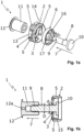
- the Figs. 1a, 1b The doubling fitting 1 shown is used for the two-dimensional adjustment and fixing of two doubled furniture panels, such as drawer fronts, side panels or panels.
- the expansion tabs 5 are cut out in the sleeve wall 13 of the expansion sleeve 2, with the axes 14 around which the expansion tabs 5 are deflected when expanded running tangentially to the sleeve wall 13. In the non-expanded state, the expansion tabs 5 protrude radially outwards beyond the sleeve wall 13 and also radially inwards into the sleeve interior, with the inner sides 15 of the expansion tabs 5 running obliquely or conically radially inwards, as seen in the tightening direction 7.
- the outer side of the inner ring 6, which interacts with the inner sides 15 of the expansion tabs 5, can also run obliquely or conically radially inwards, as seen in the tightening direction 7, in order to expand the expansion tabs 5 radially outwards.
- the inner ring 6 has a ring base 16 with a ring base opening 17 into which the threaded bolt 8 is inserted in order to engage behind the ring base 16 with the bolt head 10 in the tightening direction 7.
- the opening diameter d1 of the sleeve base opening 4 and the opening diameter d2 of the ring base opening 17 are each larger than the bolt diameter D of the threaded bolt 8.
- the sleeve nut 11 can also have an internal polygon (e.g. hexagon socket) or a polygonal outer contour (e.g. external polygon) in order to be able to turn the sleeve nut 11 using a tool.
- the threaded bolt 8 can also have a threaded hole with an internal thread into which a threaded part designed as a shaft screw with a widened screw head is screwed.
- FIG. 2 an arrangement 20 is shown with two furniture panels 21, 22 resting on one another ("doubled"), adjusted and fixed by means of the doubling fitting 1.
- a blind hole 23 with a bore diameter corresponding to the outer diameter of the expansion sleeve 2 (here 15 mm) is drilled into the outer furniture panel 21 (e.g. made of wood material) and a (through) hole 24 with a bore diameter corresponding to the shaft diameter of the sleeve nut 11 (here 10 mm) is drilled into the inner furniture panel 22.
- the expansion sleeve 2, the inner ring 6 and the threaded bolt 8 with the bolt head 10 in front are inserted into the blind hole 23.
- the expansion tabs 5 protruding radially outwards over the sleeve wall 13 are elastically deflected radially inwards against the effect of a restoring force, whereby this assembly is already pre-fixed in the blind hole 23 after insertion.
- the sleeve nut 11 is inserted into the through hole 24 and screwed onto the threaded bolt 8 until the sleeve head 12 rests against the inner furniture panel 22.
- the larger opening diameters d1, d2 of the sleeve base opening 4 and the ring base opening 17 compared to the bolt diameter D allow a two-dimensional adjustment of the furniture panels 21, 22 resting on one another of e.g. ⁇ 2mm.
- the inner ring 6 is pulled until it rests against the sleeve base 3, whereby the Spreading tabs 5 are spread radially outwards against the wall of the blind hole 23 and pressed into the wall of the blind hole 23.
- the adjusted, doubled furniture panels 21, 22 are now firmly connected to one another.
- the doubling fitting 1 can also be made up of three parts, in that the expansion sleeve 2 and the inner ring 6 are initially manufactured as a common injection-molded part with one or more predetermined breaking points, which are then broken open when the sleeve nut 11 is tightened.
Landscapes
- Engineering & Computer Science (AREA)
- General Engineering & Computer Science (AREA)
- Mechanical Engineering (AREA)
- Dowels (AREA)
- Connection Of Plates (AREA)
- Furniture Connections (AREA)
Description
- Die Erfindung betrifft einen Aufdopplungsbeschlag zum Justieren und Fixieren von zwei aufeinander aufliegenden ("aufgedoppelten") Platten, insbesondere von Möbelplatten, wie z.B. Schubladenfronten, Seitenverkleidungen oder Blenden.
- Aufdopplungsbeschläge dienen beispielsweise zur Befestigung einer Frontplatte am restlichen Möbelkorpus, z.B. eine Klappenbefestigung am Möbelkorpus, und werden üblicherweise mittels Gewindebolzen an den Möbelkorpus angeschraubt. Dabei wird ein ringförmiges Beschlaggehäuse, das von einem Bolzenkopf des Gewindebolzens hintergriffen wird, in eine Sackbohrung der Frontplatte mit einem Einschlagwerkzeug (z.B. Hammer) eingeschlagen. Eine Hülsenmutter wird in eine Durchgangsbohrung im Möbelkorpus gesteckt und mit dem Gewindebolzen verschraubt. Der gegenüber dem Bolzendurchmesser größere lichte Öffnungsdurchmesser des Beschlaggehäuses erlaubt eine zweidimensionale Justierung der aufliegenden Frontplatte zum Möbelkorpus von z.B. ±2mm. Nach der Justierung wird die Hülsenmutter angezogen, bis die Frontplatte fest am Möbelkorpus anliegt. Bei diesen bekannten Aufdopplungsbeschlägen kann das Beschlaggehäuse nicht per Hand in die Sackbohrung eingesetzt werden, sondern muss mit einem Werkzeug eingeschlagen werden, um das Beschlaggehäuse fest in der Sackbohrung zu verankern.
- Die Druckschrift
DE 80 21 658 U1 offenbart einen Aufdopplungsbeschlag mit einer Spreizhülse und einer Spreizlasche. - Demgegenüber liegt der Erfindung die Aufgabe zugrunde, einen Aufdopplungsbeschlag anzugeben, der leicht und einfach ohne Einschlagwerkzeug montiert werden kann.
- Diese Aufgabe wird erfindungsgemäß durch einen Aufdopplungsbeschlag gelöst, der aufweist:
- eine Spreizhülse, die einen Hülsenboden mit einer Hülsenbodenöffnung und mindestens eine radial nach außen aufspreizbare Spreizlasche aufweist,
- einen Innenring, der in der Spreizhülse in einer Anzugsrichtung in Richtung hin zum Hülsenboden axial verschiebbar ist, um die mindestens eine Spreizlasche radial nach außen aufzuspreizen,
- einen Gewindebolzen mit einem Gewinde und mit einem Bolzenkopf, der den Innenring in der Anzugsrichtung hintergreift, und
- ein mit dem Gewinde des Gewindebolzens verschraubbares Gewindeteil mit einem verbreiterten Kopf,
- Der erfindungsgemäße Aufdopplungsbeschlag erlaubt es, aufeinander aufliegende, aufgedoppelte Platten, wie z.B. Schubladenfronten, Seitenverkleidungen oder Blenden, zweidimensional zu justieren und in der jeweils justierten Position zu fixieren. Die Spreizhülse lässt sich per Hand, also werkzeuglos, in eine Bohrung in einer Platte einsetzen, wobei bei der weiteren Montage die mindestens eine Spreizlasche von dem Innenring aufgespreizt wird, um dadurch die Spreizhülse in der Bohrung zu verankern.
- Bevorzugt steht die mindestens eine Spreizlasche im nichtgespreizten Zustand radial nach innen in das Hülseninnere vor, um so mit dem Innenring zusammenzuwirken. Außerdem kann die mindestens eine Spreizlasche im nichtgespreizten Zustand radial nach außen über die Hülsenwand vorstehen, so dass beim Einsetzen der Spreizhülse in eine passgenaue Bohrung die mindestens eine Spreizlasche gegen die Wirkung einer Rückstellkraft elastisch radial nach innen ausgelenkt wird, wodurch die Spreizhülse nach dem Einsetzen bereits in der Bohrung vorfixiert ist.
- Besonders bevorzugt verlaufen die Innenseite der mindestens einen Spreizlasche und/oder die Außenseite des Innenrings, gesehen in Anzugsrichtung, schräg oder konisch radial nach innen, um durch Heranziehen des Innenrings die mindestens eine Spreizlasche radial nach außen aufzuspreizen.
- Die mindestens eine Spreizlasche kann in der Hülsenwand freigespart sein. Vorteilhaft verläuft die Achse, um welche die mindestens eine Spreizlasche beim Aufspreizen ausgelenkt wird, tangential zur Hülsenwand der Spreizhülse.
- In einer Ausführungsform des erfindungsgemäßen Aufdopplungsbeschlags weist der Innenring einen Ringboden mit einer Ringbodenöffnung auf, die den lichten Öffnungsdurchmesser des Innenrings ausbildet. Der Bolzenkopf hintergreift den Ringboden in Anzugsrichtung, um den Innenring in der Anzugsrichtung mitzunehmen.
- Besonders bevorzugt weist die Spreizhülse mehrere, insbesondere drehsymmetrisch um die Längsachse der Spreizhülse herum angeordnete, Spreizlaschen auf.
- Das Gewindeteil kann vorteilhaft einen einfachen oder kreuzförmigen Betätigungsschlitz oder eine Betätigungskontur, wie z.B. einen Innen- oder Außenmehrkant, aufweisen, um das Gewindeteil mithilfe eines Werkzeuges verdrehen zu können.
- Vorzugsweise ist das Gewindeteil, sofern der Gewindebolzen ein Außengewinde aufweist, als Hülsen- oder Schaftmutter ausgebildet, aber kann, sofern der Gewindebolzen ein Innengewinde aufweist, alternativ auch als Schaftschraube ausgebildet sein.
- Die Erfindung betrifft in einem weiteren Aspekt auch eine Anordnung mit zwei aufeinander liegenden Platten, insbesondere Möbelplatten, und mit einem wie oben beschriebenen Aufdopplungsbeschlag, wobei die Spreizhülse, der Innenring und der Gewindebolzen mit dem Bolzenkopf voran in eine Sackbohrung in der einen, ersten Platte und das Gewindeteil in eine Bohrung in der anderen, zweiten Platte eingesetzt und miteinander verschraubt sind und wobei die mindestens eine Spreizlasche von dem Innenring radial nach außen gegen die Wand der Sackbohrung der ersten Platte aufgespreizt ist.
- Weitere Vorteile der Erfindung ergeben sich aus der Beschreibung, den Ansprüchen und der Zeichnung. Ebenso können die vorstehend genannten und die noch weiter aufgeführten Merkmale je für sich oder zu mehreren in beliebigen Kombinationen Verwendung finden. Die gezeigten und beschriebenen Ausführungsformen sind nicht als abschließende Aufzählung zu verstehen, sondern haben vielmehr beispielhaften Charakter für die Schilderung der Erfindung.
- Es zeigen:
- Fign. 1a, 1b
- den erfindungsgemäße Aufdopplungsbeschlag in einer Explosionsdarstellung (
Fig. 1a ) sowie in einem Längsschnitt (Fig. 1b ) ohne einen inFig. 1a gezeigten Innenring; und - Fig. 2
- eine erfindungsgemäße Anordnung mit zwei mittels des Aufdopplungsbeschlags justierten, aufgedoppelten Möbelplatten.
- Der in
Fign. 1a, 1b gezeigte Aufdopplungsbeschlag 1 dient zum zweidimensionalen Justieren und Fixieren von zwei aufgedoppelten Möbelplatten, wie z.B. Schubladenfronten, Seitenverkleidungen oder Blenden. - Der Aufdopplungsbeschlag 1 weist folgende Einzelteile auf:
- eine Spreizhülse 2 aus z.B. Kunststoff (Außendurchmesser z.B. 15 mm), die einen Hülsenboden 3 mit einer Hülsenbodenöffnung 4 und mehrere radial nach außen aufspreizbare Spreizlaschen 5 aufweist, welche drehsymmetrisch um die Längsachse der Spreizhülse 2 herum angeordnet sind,
- einen Innenring 6 aus z.B. Kunststoff, der in der Spreizhülse 2 in einer Anzugsrichtung 7 in Richtung hin zur Anlage an den Hülsenboden 3 axial verschiebbar ist, um die Spreizlaschen 5 radial nach außen aufzuspreizen,
- einen Gewindebolzen 8 mit einem Außengewinde 9 und mit einem Bolzenkopf 10, der den Innenring 6 in der Anzugsrichtung 7 hintergreift, und
- ein auf das Außengewinde 9 des Gewindebolzens 8 schraubbares Gewindeteil in Form einer Schaft- oder Hülsenmutter 11 (z.B. Außendurchmesser 10 mm) mit einem verbreiterten Hülsenkopf 12, welcher einen Betätigungsschlitz 12a aufweist.
- Die Spreizlaschen 5 sind in der Hülsenwand 13 der Spreizhülse 2 freigespart, wobei die Achsen 14, um welche die Spreizlaschen 5 beim Aufspreizen jeweils ausgelenkt werden, tangential zur Hülsenwand 13 verlaufen. Im nichtgespreizten Zustand stehen die Spreizlaschen 5 über die Hülsenwand 13 radial nach außen vor sowie auch in das Hülseninnere radial nach innen vor, wobei die Innenseiten 15 der Spreizlaschen 5, gesehen in Anzugsrichtung 7, schräg oder konisch radial nach innen verlaufen. Alternativ oder zusätzlich kann auch die mit den Innenseiten 15 der Spreizlaschen 5 zusammenwirkende Außenseite des Innenrings 6, gesehen in Anzugsrichtung 7, schräg oder konisch radial nach innen verlaufen, um die Spreizlaschen 5 radial nach außen aufzuspreizen.
- Der Innenring 6 hat einen Ringboden 16 mit einer Ringbodenöffnung 17, in die der Gewindebolzen 8 eingeführt ist, um mit dem Bolzenkopf 10 den Ringboden 16 in Anzugsrichtung 7 zu hintergreifen.
- Der Öffnungsdurchmesser d1 der Hülsenbodenöffnung 4 und der Öffnungsdurchmesser d2 der Ringbodenöffnung 17 sind jeweils größer als der Bolzendurchmesser D des Gewindebolzens 8.
- Statt dem gezeigten Betätigungsschlitz 13 kann die Hülsenmutter 11 auch einen Innenmehrkant (z.B. Innensechskant) oder eine polygonale Außenkontur (z.B. Außenmehrkant) aufweisen, um die Hülsenmutter 11 mithilfe eines Werkzeuges verdrehen zu können. Statt dem gezeigten Außenwinde 9 kann der Gewindebolzen 8 auch eine Gewindebohrung mit Innengewinde aufweisen, in das ein als Schaftschraube mit verbreitertem Schraubenkopf ausgebildetes Gewindeteil eingeschraubt wird.
- In
Fig. 2 ist eine Anordnung 20 mit zwei aufeinander aufliegenden ("aufgedoppelten"), mittels des Aufdopplungsbeschlags 1 justierten und fixierten Möbelplatten 21, 22 gezeigt. In die außenseitige Möbelplatte 21 (z.B. aus Holzwerkstoff) ist eine Sackbohrung 23 mit einem dem Außendurchmesser der Spreizhülse 2 entsprechenden Bohrungsdurchmesser (hier 15 mm) und in die innenseitige Möbelplatte 22 eine (Durchgangs)Bohrung 24 mit einem dem Schaftdurchmesser der Hülsenmutter 11 entsprechenden Bohrungsdurchmesser (hier 10 mm) gebohrt. Die Spreizhülse 2, der Innenring 6 und der Gewindebolzen 8 mit dem Bolzenkopf 10 voran sind in die Sackbohrung 23 eingesetzt. Dabei sind die radial nach außen über die Hülsenwand 13 vorstehenden Spreizlaschen 5 gegen die Wirkung einer Rückstellkraft elastisch radial nach innen ausgelenkt, wodurch diese Baugruppe nach dem Einsetzen bereits in der Sackbohrung 23 vorfixiert ist. Die Hülsenmutter 11 ist in die Durchgangsbohrung 24 eingesteckt und auf den Gewindebolzen 8 aufgeschraubt, bis der Hülsenkopf 12 an der innenliegenden Möbelplatte 22 anliegt. - Die gegenüber dem Bolzendurchmesser D größeren Öffnungsdurchmesser d1, d2 der Hülsenbodenöffnung 4 und der Ringbodenöffnung 17 erlauben eine zweidimensionale Justierung der aufeinander aufliegenden Möbelplatten 21, 22 von z.B. ±2mm. Bei der finalen Befestigung durch Anziehen der Hülsenmutter 11 wird der Innenring 6 bis zur Anlage an den Hülsenboden 3 herangezogen, wodurch die Spreizlaschen 5 radial nach außen gegen die Wand der Sackbohrung 23 aufgespreizt und in die Wand der Sackbohrung 23 gedrückt werden. Die justierten, aufgedoppelten Möbelplatten 21, 22 sind nun fest miteinander verbunden.
- Statt wie gezeigt vierteilig kann der Aufdopplungsbeschlag 1 auch dreiteilig ausgebildet sein, indem die Spreizhülse 2 und der Innenring 6 zunächst als ein gemeinsames Spritzgussteil mit einer oder mehreren Sollbruchstellen gefertigt sind, welche dann beim Anziehen der Hülsenmutter 11 aufgebrochen werden.
Claims (12)
- Aufdopplungsbeschlag (1) aufweisend- eine Spreizhülse (2), die einen Hülsenboden (3) mit einer Hülsenbodenöffnung (4) und mindestens eine radial nach außen aufspreizbare Spreizlasche (5) aufweist, dadurch gekennzeichnet, dass der Aufdopplungsbeschlag (1) ferner aufweist:wobei der Öffnungsdurchmesser (d1) der Hülsenbodenöffnung (4) und der lichte Öffnungsdurchmesser (d2) des Innenrings (6) jeweils größer als der Bolzendurchmesser (D) des Gewindebolzens (8) sind.- einen Innenring (6), der in der Spreizhülse (2) in einer Anzugsrichtung (7) in Richtung hin zum Hülsenboden (3) axial verschiebbar ist, um die mindestens eine Spreizlasche (5) radial nach außen aufzuspreizen,- einen Gewindebolzen (8) mit einem Gewinde (9) und mit einem Bolzenkopf (10), der den Innenring (6) in der Anzugsrichtung (7) hintergreift, und- ein mit dem Gewinde (9) des Gewindebolzens (8) verschraubbares Gewindeteil (11) mit einem verbreiterten Kopf (12),
- Aufdopplungsbeschlag nach Anspruch 1, dadurch gekennzeichnet, dass der Innenring (6) in der Spreizhülse (2) in Anzugsrichtung (7) bis zur Anlage an den Hülsenboden (3) axial verschiebbar ist, um die mindestens eine Spreizlasche (5) radial nach außen aufzuspreizen.
- Aufdopplungsbeschlag nach Anspruch 1 oder 2, dadurch gekennzeichnet, dass die mindestens eine Spreizlasche (5) im nichtgespreizten Zustand radial nach innen in das Hülseninnere vorsteht.
- Aufdopplungsbeschlag nach einem der vorhergehenden Ansprüche, dadurch gekennzeichnet, dass die mindestens eine Spreizlasche (5) im nichtgespreizten Zustand radial nach außen über die Hülsenwand (13) vorsteht.
- Aufdopplungsbeschlag nach einem der vorhergehenden Ansprüche, dadurch gekennzeichnet, dass die Innenseite der mindestens einen Spreizlasche (5) und/oder die Außenseite des Innenrings (6), gesehen in Anzugsrichtung (7), schräg oder konisch radial nach innen verlaufen.
- Aufdopplungsbeschlag nach einem der vorhergehenden Ansprüche, dadurch gekennzeichnet, dass die mindestens eine Spreizlasche (5) in der Hülsenwand (13) freigespart ist.
- Aufdopplungsbeschlag nach einem der vorhergehenden Ansprüche, dadurch gekennzeichnet, dass die Achse (14), um welche die mindestens eine Spreizlasche (5) beim Aufspreizen ausgelenkt wird, tangential zur Hülsenwand (13) der Spreizhülse (2) verläuft.
- Aufdopplungsbeschlag nach einem der vorhergehenden Ansprüche, dadurch gekennzeichnet, dass der Innenring (6) einen Ringboden (16) aufweist, dass der lichte Öffnungsdurchmesser (d2) des Innenrings (6) durch eine Ringbodenöffnung (17) in dem Ringboden (16) gebildet ist und dass der Bolzenkopf (10) den Ringboden (16) in Anzugsrichtung (7) hintergreift.
- Aufdopplungsbeschlag nach einem der vorhergehenden Ansprüche, dadurch gekennzeichnet, dass die Spreizhülse (2) mehrere, insbesondere drehsymmetrisch um die Längsachse der Spreizhülse (2) herum angeordnete, Spreizlaschen (3) aufweist.
- Aufdopplungsbeschlag nach einem der vorhergehenden Ansprüche, dadurch gekennzeichnet, dass das Gewindeteil (11) einen Betätigungsschlitz (13) oder eine Betätigungskontur aufweist.
- Aufdopplungsbeschlag nach einem der vorhergehenden Ansprüche, dadurch gekennzeichnet, dass das Gewindeteil (11) als Hülsen- oder Schaftmutter ausgebildet ist.
- Anordnung (20) mit zwei aufeinander liegenden Platten (21, 22), insbesondere Möbelplatten, und mit einem Aufdopplungsbeschlag (1) nach einem der vorhergehenden Ansprüche, wobei die Spreizhülse (2), der Innenring (6) und der Gewindebolzen (8) mit dem Bolzenkopf (10) voran in eine Sackbohrung (23) in der einen, ersten Platte (21) und das Gewindeteil (11) in eine Bohrung (24) in der anderen, zweiten Platte (22) eingesetzt und miteinander verschraubt sind und wobei die mindestens eine Spreizlasche (5) von dem Innenring (6) radial nach außen gegen die Wand der Sackbohrung (23) der ersten Platte (21) aufgespreizt ist.
Applications Claiming Priority (2)
| Application Number | Priority Date | Filing Date | Title |
|---|---|---|---|
| DE202020105956.4U DE202020105956U1 (de) | 2020-10-19 | 2020-10-19 | Aufdopplungsbeschlag und zugehörige Anordnung mit zwei aufgedoppelten Platten |
| PCT/EP2021/076761 WO2022083989A1 (de) | 2020-10-19 | 2021-09-29 | Aufdopplungsbeschlag und zugehörige anordnung mit zwei aufgedoppelten platten |
Publications (2)
| Publication Number | Publication Date |
|---|---|
| EP4229308A1 EP4229308A1 (de) | 2023-08-23 |
| EP4229308B1 true EP4229308B1 (de) | 2024-09-25 |
Family
ID=73264642
Family Applications (1)
| Application Number | Title | Priority Date | Filing Date |
|---|---|---|---|
| EP21786370.3A Active EP4229308B1 (de) | 2020-10-19 | 2021-09-29 | Aufdopplungsbeschlag und zugehörige anordnung mit zwei aufgedoppelten platten |
Country Status (5)
| Country | Link |
|---|---|
| US (1) | US20230243374A1 (de) |
| EP (1) | EP4229308B1 (de) |
| DE (1) | DE202020105956U1 (de) |
| PL (1) | PL4229308T3 (de) |
| WO (1) | WO2022083989A1 (de) |
Families Citing this family (1)
| Publication number | Priority date | Publication date | Assignee | Title |
|---|---|---|---|---|
| DE102020119747B4 (de) * | 2020-07-27 | 2022-12-08 | Miele & Cie. Kg | Verfahren zur lösbaren Verbindung eines Einbaugeräts mit einem Möbelteil und System zur Durchführung eines solchen Verfahrens |
Family Cites Families (22)
| Publication number | Priority date | Publication date | Assignee | Title |
|---|---|---|---|---|
| US2639179A (en) * | 1950-03-31 | 1953-05-19 | Weber Knapp Co | Self-aligning, screw-threaded fastening device |
| US3227029A (en) * | 1961-08-04 | 1966-01-04 | Devine James Henry | Self-contained ratchet-like fastener with centering sleeve and center component |
| US3145669A (en) * | 1962-01-26 | 1964-08-25 | Chicago Hardware Foundry Compa | Locking mechanism |
| US3114528A (en) * | 1962-11-07 | 1963-12-17 | Lester W Forest | Base and lock assembly for pipe |
| DE8021658U1 (de) * | 1979-09-26 | 1980-11-13 | Julius Blum Gmbh, Hoechst (Oesterreich) | Möbelbeschlag für die Befestigung einer Frontplatte |
| US4592687A (en) * | 1985-07-22 | 1986-06-03 | Raymond Piersall | Roof bolt |
| US4875266A (en) * | 1985-11-27 | 1989-10-24 | Batten Ronald W | Releasable high torque fastener |
| US5161916A (en) * | 1991-06-03 | 1992-11-10 | White Claude C | Self-seating expansion anchor |
| US5685678A (en) * | 1995-02-21 | 1997-11-11 | Giannuzzi; Anthony C. | Fail-safe anchor bolt assembly for cracked masonry |
| DE10105407A1 (de) * | 2001-02-07 | 2002-08-08 | Hilti Ag | Spreizanker |
| GB0328043D0 (en) * | 2003-12-03 | 2004-01-07 | Hoy Kevin D | Anchoring methods and products of such methods |
| US20060182513A1 (en) * | 2005-02-15 | 2006-08-17 | Dortch John P | Fastener and method for using same |
| US8356954B2 (en) * | 2007-07-13 | 2013-01-22 | Jon Russell Koch | Assembly apparatus for modular components especially for upholstered furniture |
| WO2010111593A2 (en) * | 2009-03-27 | 2010-09-30 | Monogram Aerospace Fasteners, Inc. | Blind bolt fastener |
| US8231318B2 (en) * | 2009-04-22 | 2012-07-31 | As Ip Holdco, L.L.C. | Push and turn nut for quick faucet installation |
| US8950991B2 (en) * | 2010-10-13 | 2015-02-10 | Primordial Soup, Llc | Screw captivator |
| US8777319B2 (en) * | 2011-03-30 | 2014-07-15 | Ashley Furniture Industries, Inc. | Furniture assembly system |
| US20120311947A1 (en) * | 2011-06-07 | 2012-12-13 | John Van Wissen | Expansion anchor |
| GB201204799D0 (en) * | 2012-03-19 | 2012-05-02 | Kee Safety Ltd | Connector |
| KR101193248B1 (ko) * | 2012-06-18 | 2012-10-18 | 동양기전 주식회사 | 차량의 와이퍼 장치용 볼트 조립체 |
| US8978201B2 (en) * | 2013-08-08 | 2015-03-17 | Delphi Technologies, Inc. | Anti-rattle sleeve for a hinge joint |
| DE102015120837A1 (de) * | 2015-12-01 | 2017-06-01 | Witte Automotive Gmbh | Vorrichtung zur Anbringung eines ersten Bauteils an einem zweiten Bauteil |
-
2020
- 2020-10-19 DE DE202020105956.4U patent/DE202020105956U1/de active Active
-
2021
- 2021-09-29 WO PCT/EP2021/076761 patent/WO2022083989A1/de not_active Ceased
- 2021-09-29 PL PL21786370.3T patent/PL4229308T3/pl unknown
- 2021-09-29 EP EP21786370.3A patent/EP4229308B1/de active Active
-
2023
- 2023-04-07 US US18/297,166 patent/US20230243374A1/en not_active Abandoned
Also Published As
| Publication number | Publication date |
|---|---|
| PL4229308T3 (pl) | 2025-02-17 |
| WO2022083989A1 (de) | 2022-04-28 |
| DE202020105956U1 (de) | 2020-10-28 |
| EP4229308A1 (de) | 2023-08-23 |
| US20230243374A1 (en) | 2023-08-03 |
Similar Documents
| Publication | Publication Date | Title |
|---|---|---|
| DE69721173T2 (de) | Ankerbolzen | |
| EP1857607A2 (de) | Befestigungelement und Verfahren zur Befestigung von Dämmstoffplatten | |
| EP3176445A1 (de) | Vorrichtung zur anbringung eines ersten bauteils an einem zweiten bauteil | |
| EP3658785B1 (de) | Spreizbolzen sowie verbindungsanordnung mit einem solchen spreizbolzen | |
| EP0477713B1 (de) | Vorrichtung zur Befestigung eines insbesondere rohrförmigen Bauteils an einer Wand oder dergleichen | |
| EP2827006A1 (de) | Blindnietsystem | |
| EP0477707B1 (de) | Verbindungseinrichtung für ein insbesondere rohrförmiges Bauteil | |
| EP0564889A1 (de) | Verbindungseinrichtung für ein insbesondere rohrförmiges Bauteil | |
| WO2013120746A1 (de) | Befestigungsanker und befestigungssystem mit befestigungsanker | |
| DE102012108779A1 (de) | Profilverbindung | |
| DE102005051243A1 (de) | Befestigungselement zum Befestigen in einem Durchgangsloch in einer Platte bei einseitiger Zugänglichkeit, Setzwerkzeug und Demontagewerkzeug für das Befestigungselement | |
| EP2627915B1 (de) | Verankerungseinrichtung zum befestigen eines bauteils an einem trägerelement | |
| EP2905392A1 (de) | Dübel und Setzverfahren zur Befestigung von Dämmstoffen | |
| WO2022083989A1 (de) | Aufdopplungsbeschlag und zugehörige anordnung mit zwei aufgedoppelten platten | |
| EP2971400A1 (de) | Tülle und befestigungselement zum befestigen einer materialschicht | |
| EP1651873A1 (de) | Vorrichtung mit zwei durch eine verbindungsschraube zusammengehaltenen hohlprofilen sowie werkzeug dazu | |
| EP2112301A1 (de) | Griffrosette für einen Handgriff eines Beschlags | |
| DE19520130A1 (de) | Formschlüssig setzbarer Hinterschnitt-Anker | |
| EP3755503B1 (de) | Setzwerkzeug und setzverfahren für bolzenanker | |
| EP4240980B1 (de) | Aufdopplungsbeschlag und zugehörige anordnung mit zwei aufgedoppelten platten | |
| EP0388694A1 (de) | Spreizdübel | |
| DE102010055808A1 (de) | Befestigungsvorrichtung | |
| WO2018134108A1 (de) | Unterlegscheibe, befestigungsanordnung und verwendung der unterlegscheibe | |
| DE202014005249U1 (de) | Spreizanker | |
| WO2022047515A1 (de) | Platte zur plattenosteosynthese, befestigungselement und set |
Legal Events
| Date | Code | Title | Description |
|---|---|---|---|
| STAA | Information on the status of an ep patent application or granted ep patent |
Free format text: STATUS: UNKNOWN |
|
| STAA | Information on the status of an ep patent application or granted ep patent |
Free format text: STATUS: THE INTERNATIONAL PUBLICATION HAS BEEN MADE |
|
| PUAI | Public reference made under article 153(3) epc to a published international application that has entered the european phase |
Free format text: ORIGINAL CODE: 0009012 |
|
| STAA | Information on the status of an ep patent application or granted ep patent |
Free format text: STATUS: REQUEST FOR EXAMINATION WAS MADE |
|
| 17P | Request for examination filed |
Effective date: 20230519 |
|
| AK | Designated contracting states |
Kind code of ref document: A1 Designated state(s): AL AT BE BG CH CY CZ DE DK EE ES FI FR GB GR HR HU IE IS IT LI LT LU LV MC MK MT NL NO PL PT RO RS SE SI SK SM TR |
|
| DAV | Request for validation of the european patent (deleted) | ||
| DAX | Request for extension of the european patent (deleted) | ||
| GRAP | Despatch of communication of intention to grant a patent |
Free format text: ORIGINAL CODE: EPIDOSNIGR1 |
|
| STAA | Information on the status of an ep patent application or granted ep patent |
Free format text: STATUS: GRANT OF PATENT IS INTENDED |
|
| INTG | Intention to grant announced |
Effective date: 20240502 |
|
| GRAS | Grant fee paid |
Free format text: ORIGINAL CODE: EPIDOSNIGR3 |
|
| GRAA | (expected) grant |
Free format text: ORIGINAL CODE: 0009210 |
|
| STAA | Information on the status of an ep patent application or granted ep patent |
Free format text: STATUS: THE PATENT HAS BEEN GRANTED |
|
| AK | Designated contracting states |
Kind code of ref document: B1 Designated state(s): AL AT BE BG CH CY CZ DE DK EE ES FI FR GB GR HR HU IE IS IT LI LT LU LV MC MK MT NL NO PL PT RO RS SE SI SK SM TR |
|
| REG | Reference to a national code |
Ref country code: GB Ref legal event code: FG4D Free format text: NOT ENGLISH |
|
| REG | Reference to a national code |
Ref country code: CH Ref legal event code: EP |
|
| REG | Reference to a national code |
Ref country code: DE Ref legal event code: R096 Ref document number: 502021005266 Country of ref document: DE |
|
| REG | Reference to a national code |
Ref country code: IE Ref legal event code: FG4D Free format text: LANGUAGE OF EP DOCUMENT: GERMAN |
|
| REG | Reference to a national code |
Ref country code: LT Ref legal event code: MG9D |
|
| PG25 | Lapsed in a contracting state [announced via postgrant information from national office to epo] |
Ref country code: NO Free format text: LAPSE BECAUSE OF FAILURE TO SUBMIT A TRANSLATION OF THE DESCRIPTION OR TO PAY THE FEE WITHIN THE PRESCRIBED TIME-LIMIT Effective date: 20241225 |
|
| PG25 | Lapsed in a contracting state [announced via postgrant information from national office to epo] |
Ref country code: GR Free format text: LAPSE BECAUSE OF FAILURE TO SUBMIT A TRANSLATION OF THE DESCRIPTION OR TO PAY THE FEE WITHIN THE PRESCRIBED TIME-LIMIT Effective date: 20241226 Ref country code: FI Free format text: LAPSE BECAUSE OF FAILURE TO SUBMIT A TRANSLATION OF THE DESCRIPTION OR TO PAY THE FEE WITHIN THE PRESCRIBED TIME-LIMIT Effective date: 20240925 |
|
| PG25 | Lapsed in a contracting state [announced via postgrant information from national office to epo] |
Ref country code: BG Free format text: LAPSE BECAUSE OF FAILURE TO SUBMIT A TRANSLATION OF THE DESCRIPTION OR TO PAY THE FEE WITHIN THE PRESCRIBED TIME-LIMIT Effective date: 20240925 |
|
| PG25 | Lapsed in a contracting state [announced via postgrant information from national office to epo] |
Ref country code: LV Free format text: LAPSE BECAUSE OF FAILURE TO SUBMIT A TRANSLATION OF THE DESCRIPTION OR TO PAY THE FEE WITHIN THE PRESCRIBED TIME-LIMIT Effective date: 20240925 |
|
| PG25 | Lapsed in a contracting state [announced via postgrant information from national office to epo] |
Ref country code: RS Free format text: LAPSE BECAUSE OF FAILURE TO SUBMIT A TRANSLATION OF THE DESCRIPTION OR TO PAY THE FEE WITHIN THE PRESCRIBED TIME-LIMIT Effective date: 20241225 |
|
| REG | Reference to a national code |
Ref country code: NL Ref legal event code: MP Effective date: 20240925 |
|
| PG25 | Lapsed in a contracting state [announced via postgrant information from national office to epo] |
Ref country code: RS Free format text: LAPSE BECAUSE OF FAILURE TO SUBMIT A TRANSLATION OF THE DESCRIPTION OR TO PAY THE FEE WITHIN THE PRESCRIBED TIME-LIMIT Effective date: 20241225 Ref country code: NO Free format text: LAPSE BECAUSE OF FAILURE TO SUBMIT A TRANSLATION OF THE DESCRIPTION OR TO PAY THE FEE WITHIN THE PRESCRIBED TIME-LIMIT Effective date: 20241225 Ref country code: LV Free format text: LAPSE BECAUSE OF FAILURE TO SUBMIT A TRANSLATION OF THE DESCRIPTION OR TO PAY THE FEE WITHIN THE PRESCRIBED TIME-LIMIT Effective date: 20240925 Ref country code: GR Free format text: LAPSE BECAUSE OF FAILURE TO SUBMIT A TRANSLATION OF THE DESCRIPTION OR TO PAY THE FEE WITHIN THE PRESCRIBED TIME-LIMIT Effective date: 20241226 Ref country code: FI Free format text: LAPSE BECAUSE OF FAILURE TO SUBMIT A TRANSLATION OF THE DESCRIPTION OR TO PAY THE FEE WITHIN THE PRESCRIBED TIME-LIMIT Effective date: 20240925 Ref country code: BG Free format text: LAPSE BECAUSE OF FAILURE TO SUBMIT A TRANSLATION OF THE DESCRIPTION OR TO PAY THE FEE WITHIN THE PRESCRIBED TIME-LIMIT Effective date: 20240925 |
|
| PG25 | Lapsed in a contracting state [announced via postgrant information from national office to epo] |
Ref country code: NL Free format text: LAPSE BECAUSE OF FAILURE TO SUBMIT A TRANSLATION OF THE DESCRIPTION OR TO PAY THE FEE WITHIN THE PRESCRIBED TIME-LIMIT Effective date: 20240925 |
|
| PG25 | Lapsed in a contracting state [announced via postgrant information from national office to epo] |
Ref country code: IS Free format text: LAPSE BECAUSE OF FAILURE TO SUBMIT A TRANSLATION OF THE DESCRIPTION OR TO PAY THE FEE WITHIN THE PRESCRIBED TIME-LIMIT Effective date: 20250125 Ref country code: PT Free format text: LAPSE BECAUSE OF FAILURE TO SUBMIT A TRANSLATION OF THE DESCRIPTION OR TO PAY THE FEE WITHIN THE PRESCRIBED TIME-LIMIT Effective date: 20250127 |
|
| PG25 | Lapsed in a contracting state [announced via postgrant information from national office to epo] |
Ref country code: SM Free format text: LAPSE BECAUSE OF FAILURE TO SUBMIT A TRANSLATION OF THE DESCRIPTION OR TO PAY THE FEE WITHIN THE PRESCRIBED TIME-LIMIT Effective date: 20240925 Ref country code: RO Free format text: LAPSE BECAUSE OF FAILURE TO SUBMIT A TRANSLATION OF THE DESCRIPTION OR TO PAY THE FEE WITHIN THE PRESCRIBED TIME-LIMIT Effective date: 20240925 |
|
| PG25 | Lapsed in a contracting state [announced via postgrant information from national office to epo] |
Ref country code: ES Free format text: LAPSE BECAUSE OF FAILURE TO SUBMIT A TRANSLATION OF THE DESCRIPTION OR TO PAY THE FEE WITHIN THE PRESCRIBED TIME-LIMIT Effective date: 20240925 |
|
| PG25 | Lapsed in a contracting state [announced via postgrant information from national office to epo] |
Ref country code: EE Free format text: LAPSE BECAUSE OF FAILURE TO SUBMIT A TRANSLATION OF THE DESCRIPTION OR TO PAY THE FEE WITHIN THE PRESCRIBED TIME-LIMIT Effective date: 20240925 |
|
| PG25 | Lapsed in a contracting state [announced via postgrant information from national office to epo] |
Ref country code: CZ Free format text: LAPSE BECAUSE OF FAILURE TO SUBMIT A TRANSLATION OF THE DESCRIPTION OR TO PAY THE FEE WITHIN THE PRESCRIBED TIME-LIMIT Effective date: 20240925 |
|
| PG25 | Lapsed in a contracting state [announced via postgrant information from national office to epo] |
Ref country code: SK Free format text: LAPSE BECAUSE OF FAILURE TO SUBMIT A TRANSLATION OF THE DESCRIPTION OR TO PAY THE FEE WITHIN THE PRESCRIBED TIME-LIMIT Effective date: 20240925 Ref country code: IT Free format text: LAPSE BECAUSE OF FAILURE TO SUBMIT A TRANSLATION OF THE DESCRIPTION OR TO PAY THE FEE WITHIN THE PRESCRIBED TIME-LIMIT Effective date: 20240925 |
|
| REG | Reference to a national code |
Ref country code: CH Ref legal event code: PL |
|
| PG25 | Lapsed in a contracting state [announced via postgrant information from national office to epo] |
Ref country code: LU Free format text: LAPSE BECAUSE OF NON-PAYMENT OF DUE FEES Effective date: 20240929 |
|
| REG | Reference to a national code |
Ref country code: DE Ref legal event code: R097 Ref document number: 502021005266 Country of ref document: DE |
|
| PG25 | Lapsed in a contracting state [announced via postgrant information from national office to epo] |
Ref country code: MC Free format text: LAPSE BECAUSE OF FAILURE TO SUBMIT A TRANSLATION OF THE DESCRIPTION OR TO PAY THE FEE WITHIN THE PRESCRIBED TIME-LIMIT Effective date: 20240925 |
|
| PG25 | Lapsed in a contracting state [announced via postgrant information from national office to epo] |
Ref country code: DK Free format text: LAPSE BECAUSE OF FAILURE TO SUBMIT A TRANSLATION OF THE DESCRIPTION OR TO PAY THE FEE WITHIN THE PRESCRIBED TIME-LIMIT Effective date: 20240925 |
|
| REG | Reference to a national code |
Ref country code: BE Ref legal event code: MM Effective date: 20240930 |
|
| PG25 | Lapsed in a contracting state [announced via postgrant information from national office to epo] |
Ref country code: BE Free format text: LAPSE BECAUSE OF NON-PAYMENT OF DUE FEES Effective date: 20240930 |
|
| PG25 | Lapsed in a contracting state [announced via postgrant information from national office to epo] |
Ref country code: CH Free format text: LAPSE BECAUSE OF NON-PAYMENT OF DUE FEES Effective date: 20240930 |
|
| PG25 | Lapsed in a contracting state [announced via postgrant information from national office to epo] |
Ref country code: IE Free format text: LAPSE BECAUSE OF NON-PAYMENT OF DUE FEES Effective date: 20240929 |
|
| PLBE | No opposition filed within time limit |
Free format text: ORIGINAL CODE: 0009261 |
|
| STAA | Information on the status of an ep patent application or granted ep patent |
Free format text: STATUS: NO OPPOSITION FILED WITHIN TIME LIMIT |
|
| 26N | No opposition filed |
Effective date: 20250626 |
|
| PG25 | Lapsed in a contracting state [announced via postgrant information from national office to epo] |
Ref country code: SE Free format text: LAPSE BECAUSE OF FAILURE TO SUBMIT A TRANSLATION OF THE DESCRIPTION OR TO PAY THE FEE WITHIN THE PRESCRIBED TIME-LIMIT Effective date: 20240925 |
|
| PGFP | Annual fee paid to national office [announced via postgrant information from national office to epo] |
Ref country code: DE Payment date: 20250926 Year of fee payment: 5 |
|
| PGFP | Annual fee paid to national office [announced via postgrant information from national office to epo] |
Ref country code: PL Payment date: 20250811 Year of fee payment: 5 |
|
| PG25 | Lapsed in a contracting state [announced via postgrant information from national office to epo] |
Ref country code: FR Free format text: LAPSE BECAUSE OF NON-PAYMENT OF DUE FEES Effective date: 20241125 |
|
| PGFP | Annual fee paid to national office [announced via postgrant information from national office to epo] |
Ref country code: AT Payment date: 20251020 Year of fee payment: 5 |
|
| PG25 | Lapsed in a contracting state [announced via postgrant information from national office to epo] |
Ref country code: HR Free format text: LAPSE BECAUSE OF FAILURE TO SUBMIT A TRANSLATION OF THE DESCRIPTION OR TO PAY THE FEE WITHIN THE PRESCRIBED TIME-LIMIT Effective date: 20240925 |
|
| PG25 | Lapsed in a contracting state [announced via postgrant information from national office to epo] |
Ref country code: CY Free format text: LAPSE BECAUSE OF FAILURE TO SUBMIT A TRANSLATION OF THE DESCRIPTION OR TO PAY THE FEE WITHIN THE PRESCRIBED TIME-LIMIT; INVALID AB INITIO Effective date: 20210929 |
|
| PG25 | Lapsed in a contracting state [announced via postgrant information from national office to epo] |
Ref country code: HU Free format text: LAPSE BECAUSE OF FAILURE TO SUBMIT A TRANSLATION OF THE DESCRIPTION OR TO PAY THE FEE WITHIN THE PRESCRIBED TIME-LIMIT; INVALID AB INITIO Effective date: 20210929 |