EP4229171B1 - Bioreaktor mit sonde für elektrische oder elektromagnetische messungen - Google Patents
Bioreaktor mit sonde für elektrische oder elektromagnetische messungen Download PDFInfo
- Publication number
- EP4229171B1 EP4229171B1 EP21778165.7A EP21778165A EP4229171B1 EP 4229171 B1 EP4229171 B1 EP 4229171B1 EP 21778165 A EP21778165 A EP 21778165A EP 4229171 B1 EP4229171 B1 EP 4229171B1
- Authority
- EP
- European Patent Office
- Prior art keywords
- probe
- lid
- bioreactor
- vessel
- previous
- Prior art date
- Legal status (The legal status is an assumption and is not a legal conclusion. Google has not performed a legal analysis and makes no representation as to the accuracy of the status listed.)
- Active
Links
Images


Classifications
-
- C—CHEMISTRY; METALLURGY
- C12—BIOCHEMISTRY; BEER; SPIRITS; WINE; VINEGAR; MICROBIOLOGY; ENZYMOLOGY; MUTATION OR GENETIC ENGINEERING
- C12M—APPARATUS FOR ENZYMOLOGY OR MICROBIOLOGY; APPARATUS FOR CULTURING MICROORGANISMS FOR PRODUCING BIOMASS, FOR GROWING CELLS OR FOR OBTAINING FERMENTATION OR METABOLIC PRODUCTS, i.e. BIOREACTORS OR FERMENTERS
- C12M41/00—Means for regulation, monitoring, measurement or control, e.g. flow regulation
-
- C—CHEMISTRY; METALLURGY
- C12—BIOCHEMISTRY; BEER; SPIRITS; WINE; VINEGAR; MICROBIOLOGY; ENZYMOLOGY; MUTATION OR GENETIC ENGINEERING
- C12M—APPARATUS FOR ENZYMOLOGY OR MICROBIOLOGY; APPARATUS FOR CULTURING MICROORGANISMS FOR PRODUCING BIOMASS, FOR GROWING CELLS OR FOR OBTAINING FERMENTATION OR METABOLIC PRODUCTS, i.e. BIOREACTORS OR FERMENTERS
- C12M23/00—Constructional details, e.g. recesses, hinges
- C12M23/38—Caps; Covers; Plugs; Pouring means
-
- C—CHEMISTRY; METALLURGY
- C12—BIOCHEMISTRY; BEER; SPIRITS; WINE; VINEGAR; MICROBIOLOGY; ENZYMOLOGY; MUTATION OR GENETIC ENGINEERING
- C12M—APPARATUS FOR ENZYMOLOGY OR MICROBIOLOGY; APPARATUS FOR CULTURING MICROORGANISMS FOR PRODUCING BIOMASS, FOR GROWING CELLS OR FOR OBTAINING FERMENTATION OR METABOLIC PRODUCTS, i.e. BIOREACTORS OR FERMENTERS
- C12M23/00—Constructional details, e.g. recesses, hinges
- C12M23/26—Constructional details, e.g. recesses, hinges flexible
-
- C—CHEMISTRY; METALLURGY
- C12—BIOCHEMISTRY; BEER; SPIRITS; WINE; VINEGAR; MICROBIOLOGY; ENZYMOLOGY; MUTATION OR GENETIC ENGINEERING
- C12M—APPARATUS FOR ENZYMOLOGY OR MICROBIOLOGY; APPARATUS FOR CULTURING MICROORGANISMS FOR PRODUCING BIOMASS, FOR GROWING CELLS OR FOR OBTAINING FERMENTATION OR METABOLIC PRODUCTS, i.e. BIOREACTORS OR FERMENTERS
- C12M23/00—Constructional details, e.g. recesses, hinges
- C12M23/28—Constructional details, e.g. recesses, hinges disposable or single use
-
- C—CHEMISTRY; METALLURGY
- C12—BIOCHEMISTRY; BEER; SPIRITS; WINE; VINEGAR; MICROBIOLOGY; ENZYMOLOGY; MUTATION OR GENETIC ENGINEERING
- C12M—APPARATUS FOR ENZYMOLOGY OR MICROBIOLOGY; APPARATUS FOR CULTURING MICROORGANISMS FOR PRODUCING BIOMASS, FOR GROWING CELLS OR FOR OBTAINING FERMENTATION OR METABOLIC PRODUCTS, i.e. BIOREACTORS OR FERMENTERS
- C12M41/00—Means for regulation, monitoring, measurement or control, e.g. flow regulation
- C12M41/26—Means for regulation, monitoring, measurement or control, e.g. flow regulation of pH
Definitions
- the present invention relates to a bioreactor including a probe for electrical or electromagnetic measurements.
- Cell culture is a process for growing cells in an artificial environment such as a bioreactor. Often, the cells are grown whilst suspended in a culture growth medium. Monitoring and/or controlling the environment to which the cells are exposed in the bioreactor is important in order to control the physiology of the cells and the amount of target produced. Specifically, the monitoring of various parameters of the cells and/or the culture growth medium within the bioreactor is key to their control.
- Example bioreactor systems suitable for cell culture are described in US 2016/0152936 and WO 2014/020327 .
- In-line monitoring is becoming increasingly important, as it facilitates process control and process automation.
- In-line monitoring generally uses a sensor inserted directly into the culture growth medium contained in a vessel. For example, electrical or electromagnetic measurements made by electrodes immersed in growth media can be used to measure quantities such as capacitance, impedance, permittivity, conductivity etc. These measurements may then be subject to analysis techniques such as impedance spectroscopy in order to derive, for example, cell concentration.
- Probes carrying such electrodes need to be arranged so that they can be connected to electronics and communications outside the vessel bioreactor, while ensuring that the sensing end of the probe is properly immersed in the cell culture in the vessel.
- the present invention has been devised in light of the above considerations.
- the present invention provides a bioreactor according to claim 1.
- the one or more resiliently deformable mechanisms and the one or more complimentary surfaces may form a snap-fit connector.
- the one or more resiliently deformable mechanisms may be one or more flexible members, for example formed of flexible plastic.
- the resiliently deformable mechanisms may be one or more spring-loaded detent mechanisms, e.g. in which the or each resiliently deformable mechanism has a substantially rigid (non-flexible) contact member which slides against its respective complementary surface, and a spring which biases the contact member in a direction towards the complementary surface while accommodating movement of the contact member in an opposite direction.
- the probe and the lid may be configured such that the one or more resiliently deformable mechanisms are deformable by a user to allow the probe to be withdrawn from the lid and reinserted multiple times.
- the resiliently deformable mechanisms may have features which are accessible manually or by a tool so that a force can be applied to the or each mechanism which re-deforms that mechanism allowing withdrawal. This is particularly useful in the context of a snap-fit connector, which otherwise may be impossible to withdraw without damaging the mechanism.
- the lid and the probe may have respective abutment surfaces which interact to prevent the probe being over-inserted beyond the predetermined position.
- the sealing element may be sandwiched between and seal to the abutment surfaces to seal the probe to the lid when the probe is located at the predetermined position.
- the sealing element may be, for example, a gasket or an elastomeric sealing element such as O-ring.
- the probe and the aperture are keyed such that the probe can adopt only one angular (i.e. rotational) orientation around the insertion direction of the probe when the probe is located at the predetermined position.
- the sensing end is configured to make the electrical or electromagnetic measurements along a sensing direction which is not the insertion direction of the probe (for example it may be 90° to the insertion direction)
- the probe can then be secured with the sensing direction correctly aligned around the insertion direction, e.g. pointing into the centre of the vessel for a probe that is assembled off-centre in the vessel.
- the probe may have a lateral projection at its sensing end which rests against a side wall of the vessel to enforce a minimum stand-off distance between the probe and the side wall along the length of the probe from the lid to the projection.
- the minimum stand-off distance is at least 1.0 mm.
- the probe may be part of a multi-purpose assembly inserted through the aperture in the lid, the multi-purpose assembly also containing either or both of (a) a sparger for conveying sparging gas to the biological medium, and (b) further electrodes forming a pH sensor for sensing the pH of the biological medium.
- a sparger for conveying sparging gas to the biological medium
- further electrodes forming a pH sensor for sensing the pH of the biological medium.
- the lid may be removably replaceable from the vessel.
- the bioreactor may be a single-use bioreactor.
- the lid may be an integral part of the vessel, i.e. non-removably replaceable.
- the probe may be a capacitance, impedance, permittivity or conductivity probe.
- the electrical or electromagnetic measurements made by the electrodes are performed at high AC frequency. For example, they may be performed in or over a defined frequency range (e.g. 10kHz to 40 MHz).
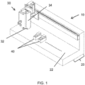
- An automated macro-scale bioreactor system 10 comprises, generally, a bed station 20 and a liquid handling station 30, which may be interconnected (as shown in Figure 1 ) or may be separate from one another.
- the bed station 20 comprises a platform 22 on which are mounted various modules.
- the modules include at least one cell culture bioreactor 40.
- the liquid handling station 30 includes a head 32 mounted on a conventional X-Y positioning robot 34.
- the head 32 includes components that are selectively moveable along the Z axis. The head 32 is thus capable of addressing and interacting with each of the modules.
- Each cell culture bioreactor 40 generally comprises a receiving station for removably receiving and providing temperature control of a rigid-walled bioreactor vessel 100 shown in Figures 2A-2C .
- the bioreactor vessel 100 for use with the bioreactor system 10 comprises a vessel 102 defining a chamber 104 for receiving a cell culture solution 106 having a headspace 108 above.
- the vessel is typically a macro-scale vessel, which is to say it holds a working volume of approximately 250 ml of cell culture solution 106. It will be understood, however, that the principles described with reference to this scale of vessel may be applied, mutatis mutandis, to both larger-and smaller-scale vessels.
- the vessel further comprises a lid 110 secured to the top of the vessel 102 by a friction fit between a skirt 112 overlapping a circumferential lip 114 on the upper edge of the vessel 102.
- An O-ring 116 is retained between the skirt 112 and an outer wall below the lip 114 to provide a seal between the lid 110 and the vessel 102.
- the lid 110 includes a fluid transfer port 120, on which is removably attached a cap 122.
- a sparge tube 130 has a distal end opening in the cell culture solution 106 and a proximal end terminating at a port through the lid 110.
- a gas input line 132 is connected at one end to the port and at the other end to a fluids module 150 and may include a filter (not shown).
- a stirrer 160 comprising blades 162 mounted at the base of a vertical shaft 164 is rotatably mounted within the vessel 100.
- the upper end of the shaft 164 includes a drive input 166, and is retained within the lid 110 by means of a labyrinth seal arrangement 168.
- the drive input 166 is connected to a drive train (not shown) which is powered by a motor (not shown) housed in the cell culture bioreactor 40.
- the vessel may include a sensor spot 170 (e.g. a DO sensor spot to detect the dissolved oxygen levels of the solution) disposed on a bottom wall of the vessel 102 to detect the dissolved oxygen levels of the solution 106 and to be interrogated from the exterior of the vessel 100.
- a sensor spot 170 e.g. a DO sensor spot to detect the dissolved oxygen levels of the solution
- the vessel may include a pH electrode sensor probe 180 which is received in a port in the lid 110.
- a distal end 184 of the probe 180 extends into the vessel chamber 104 so as to be covered, in use, by the cell culture medium 106 for monitoring the pH level of the medium in a known manner.
- the fluids module 150 in addition to the gas input line 132 to the sparge tube 130, may include a further gas line 136.
- Gas line 136 is a second input line, connected to a port through the lid 110 for delivery of gases into the headspace 108.
- This input line 136 may also include a filter (not shown).
- the fluids module 150 may be respectively connectable to O 2 , N 2 and CO 2 gas supplies for selective controlled delivery of those gases, alone or in combination, to the vessel via the input lines 132 and 136.
- a groove may be provided in a lower surface of the lid 110 to define a circumferentially arranged conduit 196 through which fluids evaporated from the headspace 108 can be transported to an outlet line 134, and thence to the fluids module 150.
- This outlet line 134 may also be provided with a filter (not shown), and is typically connected to sensors (not shown) for monitoring the gas and water content of the outlet fluid to provide an indicator of metabolic activity in the cell culture 106.
- a bioreactor of the present invention is fitted with a probe for making electrical or electromagnetic measurements on the cell culture solution. From these measurements it is possible to derive characteristics of the cell culture solution, such as cell concentration.
- the probe for making electrical or electromagnetic measurements on the cell culture solution.
- characteristics of the cell culture solution such as cell concentration.
- the probe is not limited to make capacitance measurements and can be used to make measure e.g. impedance, permittivity or conductivity.
- FIGs 3-11 discussed below features which are the same or correspond to features in Figure 1 and 2A-2C are denoted with the same references numbers.
- FIG 3 shows a transparent, perspective view of a bioreactor 40 having a capacitance probe 200, and suitable for use in the automated bioreactor system 10.
- the capacitance probe passes through an aperture in the lid 110.
- the aperture in this case is offset from the centre of the lid, but a centrally disposed aperture and probe may also be deployed, e.g. with the stirrer 160 replaced by a different stirring arrangement.
- Just the lid of the vessel 100 and the capacitance probe are shown in transparent, perspective view in Figure 4
- detail of the capacitance probe as it passes through the lid is shown in cross-sectional view in Figure 5
- a transverse cross-section through the bioreactor is shown in Figure 6 .
- the capacitance probe 200 has a sensing end inside the vessel and a remote end outside the vessel.
- the sensing end has four electrodes 202 (although other numbers of electrodes are possible) for immersion in the cell culture solution.
- the electrodes may be inwardly directed towards the centre of the vessel 100, as shown, or at other predetermined orientations. Another option, however, is for the electrodes to be non-directional ring electrodes.
- the remote end has a connector 204 configured for coupling to external devices and onward transmission of measurements made by the electrodes.
- a male form of the connector 204 is shown in Figure 3
- a variant female connector is shown in Figure 4 .
- the capacitance probe 200 is assembled to the lid 110 by inserting the remote end through the aperture from the underside of the lid.
- the aperture is surrounded by a collar 205 having a resiliently deformable lip 207 at the top end thereof, the lip producing a slight reduction in the cross-sectional area of the aperture.
- the probe has a pair of protuberances 206 on each side of the remote end, the protuberances of each pair being spaced apart in the insertion direction of the probe. On insertion of the probe through the aperture, the protuberances travel up the collar until the top protuberance of each pair reaches the lip.
- the reduction in the cross-sectional area of the aperture at the lip then causes the top protuberances to slide against inwardly-facing surfaces of the lip, which is deformed outwards by the passage of the protuberances.
- the lip resiles inwards and is trapped in the spaces between the pairs of protuberances, preventing the probe from being pulled or falling back through the aperture.
- the non-integral capacitance probe 200 By securing the non-integral capacitance probe 200 to the vessel through the lid 110 in this way, correct vertical location of the electrodes 202 of the sensing end in the vessel 100 can be assured. Moreover, the assembly can be performed speedily and without recourse to glues which could contaminate the cell culture. Nonetheless, by supplying a sufficient downwards force on the probe, the insertion operation can be reversed and the probe removed from the lid. Thus the probe can be easily replaced or substituted.
- the capacitance probe 200 has a flange 208 at one side and a shoulder 210 at an opposite side which form respective top surfaces that abut corresponding under surfaces of the lid 110 to prevent over-insertion of the probe beyond the predetermined insertion position.
- the capacitance probe 200 carries a sealing ring 212 on a top surface of the flange 208.
- the sealing ring locates into a correspondingly-shaped groove 214 which surrounds the entrance to the aperture at the underside of the lid 110, and is squeezed between an outwardly-facing surface of the probe and an inwardly facing surface of the lid to seal the probe to the lid when the probe is secured at the predetermined position.
- the electrodes 202 may be inwardly directed towards the centre of the vessel 100, as illustrated in Figure 6 which shows a cross-section through the bioreactor 40 at the height of one of the electrodes.
- the electric field around the electrodes is indicated by dashed lines.
- This predetermined orientation of the electrodes avoids helps to ensure there are no obstacles in the vicinity of the electrodes which could affect measurements on the cell culture solution made by the electrodes.
- the predetermined orientation of the electrodes is imposed by keying the capacitance probe 200 whereby the probe can adopt only one angular (i.e. rotational) orientation around the insertion direction of the probe.
- the probe and the aperture have a corresponding racetrack shaped cross-section, which of itself allows just two (180° apart) insertion orientations of the probe in the aperture.
- only one of these insertion orientations is actually usable due to the configuration of the flange 208 and the shoulder 210 of the probe. More particularly, these are offset from each other in the insertion direction of the probe, such that, were the probe in the wrong orientation, the flange would interfere with the abutment surface of the lid 110 for the shoulder and prevent full insertion.
- the relative stiffnesses of the protuberances and the lip can be swapped such that when the top protuberances slide against inwardly-facing surfaces of the lip, the protuberances are deformed inwards by the passage through the lip. When the top protuberances exit the aperture above the lip, the top protuberances then resile outwards.
- each mechanism comprising a spring loaded ball bearing that, in an un-inserted state of the probe protrudes from the surface of the probe, but is depressable inwards against the resistance of an internal restoring spring.
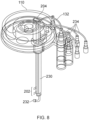
- FIG 7 shows a transparent, perspective view of a further variant bioreactor 40.
- the capacitance probe is integrated with a sparge tube and liquid feed tubes to form a multi-purpose assembly 230.
- the lid 110 of the vessel and the multi-purpose assembly are shown in transparent, perspective view in Figure 8
- detail of the multi-purpose assembly as it is inserted through the lid is shown in transparent, perspective view in in Figure 9 .
- the multi-purpose assembly 230 has a central sparge gas tube ending at a gas outlet 232 at a delivery end of the assembly inside the vessel 100, several liquid feed tubes 234 feed liquid to respective feed channels with outlets at the delivery end of the assembly above the gas outlet, and four electrodes 202 of a capacitance probe project from the delivery end of the assembly above the gas outlets.
- the remote end of the assembly outside the vessel has a connector 204 configured for coupling to external devices and onward transmission of measurements made by the electrodes.
- the multi-purpose assembly 230 passes through an aperture in the lid 110, the aperture being offset from the centre of the lid.
- the assembly is secured to the lid by inserting the delivery end, from the top side of the lid, through a rectangular aperture formed in the lid.
- the assembly has a collar 236 with a matching rectangular shape to the aperture, and a circumferential recess 238 set back from a bottom end of the collar.
- a pair of flexible plastic members 240 extend downwardly from the lid on opposite sides of the aperture. Each of these members ends in an inwardly directed barb 238.
- the barbs slide against the outward surface of the bottom end of the collar and are bent outwardly thereby. When the barbs reach the circumferential recess, they resile back inwards, in the manner of a snap-fit connector, to secure the assembly to the lid at a predetermined insertion position.
- the multi-purpose assembly 230 has a flange 244 at the top end of the collar 236, with a sealing element (not shown) being carried on the underside of the flange.
- the sealing element mediates an abutment of the bottom surface of the flange and a corresponding top surface of the lid 110 to prevent over-insertion of the assembly beyond the predetermined insertion position.
- the sealing element is also compressed by this abutment to seal the multi-purpose assembly 230 to the lid.
- the flexible plastic members 240 are accessible on the underside of the lid, and by pulling them apart, a user can withdraw the multi-purpose assembly 230 from the lid for eventual reinsertion or substitution.
- the capacitance probe is formed into a multi-purpose assembly with a sparge tube and liquid feed tubes, other combinations are possible.
- the capacitance probe can be combined in a multi-purpose assembly with the pH probe.
- Such a combined capacitance and pH probe 250 is shown in transparent, perspective view in Figure 10 .
- a sensing end of the probe has a glass membrane 252 providing a glass pH electrode structure, while set back from the glass membrane are four axially-spaced, circumferential ring electrodes 254 of a capacitance probe.
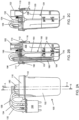
- FIG 11 shows a longitudinal partial cross-section through the vessel 100, lid 110 and capacitance probe 200 of a further variant of the bioreactor 40.
- the capacitance probe is provided with a lateral projection 260 at its sensing end and on the opposite side of the probe to the electrodes 202.
- the projection rests against the side wall of the vessel to enforce a predetermined minimum stand-off distance between the probe and the side wall along the length of the probe from the lid to the projection.
- This stand-off distance which is typically at least 1.0 mm, helps to avoid build-up of biomass solids between the probe and the side wall. When the distance is less than 1.0 mm, undesirable accumulation of biomass solids in this location has been experimentally observed.
Landscapes
- Health & Medical Sciences (AREA)
- Chemical & Material Sciences (AREA)
- Organic Chemistry (AREA)
- Life Sciences & Earth Sciences (AREA)
- Engineering & Computer Science (AREA)
- Bioinformatics & Cheminformatics (AREA)
- Zoology (AREA)
- Wood Science & Technology (AREA)
- Microbiology (AREA)
- Sustainable Development (AREA)
- Biotechnology (AREA)
- Biomedical Technology (AREA)
- Biochemistry (AREA)
- General Engineering & Computer Science (AREA)
- General Health & Medical Sciences (AREA)
- Genetics & Genomics (AREA)
- Clinical Laboratory Science (AREA)
- Analytical Chemistry (AREA)
- Apparatus Associated With Microorganisms And Enzymes (AREA)
Claims (11)
- Bioreaktor (40) umfassend:ein starrwandiges Gefäß (100) zur Aufnahme eines biologischen Mediums, wobei das Gefäß einen Deckel (110) aufweist;eine Sonde (200), die durch eine Öffnung in dem Deckel (110) hindurchgeht und ein Sensorende innerhalb des Gefäßes (100) und ein entferntes Ende außerhalb des Gefäßes aufweist, wobei das Sensorende mehrere Elektroden (202) zum Eintauchen in das biologische Medium aufweist und das entfernte Ende für die Kopplung mit externen Vorrichtungen und die Übertragung der von den Elektroden durchgeführten elektrischen oder elektromagnetischen Messungen an diese konfiguriert ist;wobei eines von dem Deckel (110) und der Sonde (200, 230, 250) einen oder mehrere elastisch verformbare Mechanismen (207, 240) aufweist und das andere von dem Deckel und der Sonde eine oder mehrere entsprechende komplementäre Oberflächen (206, 236) aufweist, wobei die elastisch verformbaren Mechanismen und die komplementären Oberflächen so konfiguriert sind, dass beim Einführen der Sonde durch die Öffnung zur Anordnung der Sonde an dem Deckel der eine oder die mehreren elastisch verformbaren Mechanismen zunächst beim Gleiten gegen die eine oder die mehreren komplementären Oberflächen verformt werden und dann zurückfedern, wenn die Sonde eine vorbestimmte Einführposition relativ zu dem Deckel erreicht, um die Sonde an dem Deckel zu befestigen; undwobei eines von dem Deckel (110) und der Sonde (200, 230, 250) ein Dichtelement (212) trägt, das die Sonde an dem Deckel abdichtet, wenn die Sonde an der vorbestimmten Position befestigt ist;dadurch gekennzeichnet, dass die Sonde (200) und die Öffnung derart verkeilt sind, dass die Sonde nur eine Winkelausrichtung um die Einführrichtung der Sonde einnehmen kann, wenn sich die Sonde an der vorbestimmten Position befindet.
- Bioreaktor (40) nach Anspruch 1, wobei der eine oder die mehreren elastisch verformbaren Mechanismen (240) und die eine oder die mehreren komplementären Oberflächen (236) eine Schnappverbindung bilden.
- Bioreaktor (40) nach Anspruch 1 oder 2, wobei der eine oder die mehreren elastisch verformbaren Mechanismen ein oder mehrere flexible Elemente oder ein oder mehrere federbelastete Rastmechanismen sind.
- Bioreaktor (40) nach einem der vorstehenden Ansprüche, wobei die Sonde (200, 230, 250) und der Deckel (110) so konfiguriert sind, dass der eine oder die mehreren elastisch verformbaren Mechanismen (207, 240) von einem Benutzer verformt werden können, damit die Sonde mehrmals aus dem Deckel herausgezogen und wieder eingeführt werden kann.
- Bioreaktor (40) nach einem der vorstehenden Ansprüche, wobei der Deckel (110) und die Sonde (200, 230, 250) jeweilige Anschlagflächen aufweisen, die zusammenwirken, um zu verhindern, dass die Sonde über die vorbestimmte Position hinaus eingeführt wird.
- Bioreaktor (40) nach Anspruch 5, wobei das Dichtelement (212) sandwichartig zwischen den Anschlagflächen angeordnet ist und diese abdichtet, um die Sonde (200, 230, 250) an dem Deckel (110) abzudichten, wenn sich die Sonde an der vorbestimmten Position befindet.
- Bioreaktor (40) nach einem der vorstehenden Ansprüche, wobei die Sonde (200) an ihrem Sensorende einen seitlichen Vorsprung (260) aufweist, der an einer Seitenwand des Gefäßes (100) anliegt, um einen Mindestabstand zwischen der Sonde und der Seitenwand entlang der Länge der Sonde von dem Deckel bis zu dem Vorsprung zu erzwingen.
- Bioreaktor (40) nach einem der vorstehenden Ansprüche, wobei die Sonde Teil einer Mehrzweckbaugruppe (230, 250) ist, die durch die Öffnung in dem Deckel eingeführt wird, wobei die Mehrzweckbaugruppe auch eines oder beide von (a) einem Sparger zum Zuführen von Einblasgas zu dem biologischen Medium und (b) weiteren Elektroden, die einen pH-Sensor zum Erfassen des pH-Werts des biologischen Mediums bilden, enthält.
- Bioreaktor (40) nach einem der vorstehenden Ansprüche, wobei der Deckel (110) von dem Gefäß (100) abnehmbar und austauschbar ist.
- Bioreaktor (40) nach einem der vorstehenden Ansprüche, welcher ein Einweg-Bioreaktor ist.
- Bioreaktor (40) nach einem der vorstehenden Ansprüche, wobei die Sonde (200, 230, 250) eine Kapazitäts-, Impedanz-, Permittivitäts- oder Leitfähigkeitssonde ist.
Applications Claiming Priority (2)
| Application Number | Priority Date | Filing Date | Title |
|---|---|---|---|
| EP20202136.6A EP3985089A1 (de) | 2020-10-15 | 2020-10-15 | Bioreaktor mit sonde für elektrische oder elektromagnetische messungen |
| PCT/EP2021/077401 WO2022078815A1 (en) | 2020-10-15 | 2021-10-05 | Bioreactor including probe for electrical or electromagnetic measurements |
Publications (2)
| Publication Number | Publication Date |
|---|---|
| EP4229171A1 EP4229171A1 (de) | 2023-08-23 |
| EP4229171B1 true EP4229171B1 (de) | 2024-03-13 |
Family
ID=72964448
Family Applications (2)
| Application Number | Title | Priority Date | Filing Date |
|---|---|---|---|
| EP20202136.6A Withdrawn EP3985089A1 (de) | 2020-10-15 | 2020-10-15 | Bioreaktor mit sonde für elektrische oder elektromagnetische messungen |
| EP21778165.7A Active EP4229171B1 (de) | 2020-10-15 | 2021-10-05 | Bioreaktor mit sonde für elektrische oder elektromagnetische messungen |
Family Applications Before (1)
| Application Number | Title | Priority Date | Filing Date |
|---|---|---|---|
| EP20202136.6A Withdrawn EP3985089A1 (de) | 2020-10-15 | 2020-10-15 | Bioreaktor mit sonde für elektrische oder elektromagnetische messungen |
Country Status (5)
| Country | Link |
|---|---|
| US (1) | US20230374436A1 (de) |
| EP (2) | EP3985089A1 (de) |
| CN (1) | CN116323907A (de) |
| DK (1) | DK4229171T3 (de) |
| WO (1) | WO2022078815A1 (de) |
Family Cites Families (11)
| Publication number | Priority date | Publication date | Assignee | Title |
|---|---|---|---|---|
| US6670817B2 (en) * | 2001-06-07 | 2003-12-30 | Heidelberger Druckmaschinen Ag | Capacitive toner level detection |
| US7879599B2 (en) * | 2005-04-22 | 2011-02-01 | Hyclone Laboratories, Inc. | Tube ports and related container systems |
| JP2007315792A (ja) * | 2006-05-23 | 2007-12-06 | Mitsubishi Electric Corp | 圧力センサの取り付け構造 |
| CA2766902C (en) * | 2009-07-06 | 2021-07-06 | Genentech, Inc. | Method of culturing eukaryotic cells |
| GB2495934A (en) * | 2011-10-25 | 2013-05-01 | Tap Biosystems Phc Ltd | Bioreactor outlet air conditioning systems and associated methods |
| US20130145818A1 (en) * | 2011-12-09 | 2013-06-13 | Mettler-Toledo Ag | Sensor unit utilizing a clamping mechanism |
| GB201213506D0 (en) | 2012-07-30 | 2012-09-12 | Tap Biosystems Phc Ltd | Bioreactor vessels and associated bioreactor systems |
| GB2515751A (en) | 2013-07-01 | 2015-01-07 | Tap Biosystems Phc Ltd | Bioreactor consumable units |
| US10557811B2 (en) * | 2013-12-06 | 2020-02-11 | Pendotech | Sensor fitting for biotech process bag |
| DE202016000554U1 (de) * | 2016-01-29 | 2017-05-08 | Eppendorf Ag | Einweg-Anschlusseinrichtung |
| KR101910118B1 (ko) * | 2017-05-25 | 2018-10-23 | 주식회사 에스피엘 | 실시간 배양환경의 모니터링 및 조절이 가능한 세포배양용기 및 이를 포함하는 세포배양시스템 |
-
2020
- 2020-10-15 EP EP20202136.6A patent/EP3985089A1/de not_active Withdrawn
-
2021
- 2021-10-05 WO PCT/EP2021/077401 patent/WO2022078815A1/en not_active Ceased
- 2021-10-05 EP EP21778165.7A patent/EP4229171B1/de active Active
- 2021-10-05 US US18/030,696 patent/US20230374436A1/en active Pending
- 2021-10-05 DK DK21778165.7T patent/DK4229171T3/da active
- 2021-10-05 CN CN202180070757.6A patent/CN116323907A/zh active Pending
Also Published As
| Publication number | Publication date |
|---|---|
| EP4229171A1 (de) | 2023-08-23 |
| DK4229171T3 (da) | 2024-04-08 |
| EP3985089A1 (de) | 2022-04-20 |
| US20230374436A1 (en) | 2023-11-23 |
| CN116323907A (zh) | 2023-06-23 |
| WO2022078815A1 (en) | 2022-04-21 |
Similar Documents
| Publication | Publication Date | Title |
|---|---|---|
| EP2544809B1 (de) | Prozessbeutelbehälter mit sensoren | |
| EP2829598B1 (de) | Sensorsondendichtung | |
| EP2155852B1 (de) | Verbesserter flexibler bioreaktor | |
| US9103703B2 (en) | Container having a sensor adapter | |
| MXPA06011832A (es) | Sistema de reactor de tanque agitado. | |
| US12319906B2 (en) | Detecting foam in a bioreactor plant | |
| EP4229171B1 (de) | Bioreaktor mit sonde für elektrische oder elektromagnetische messungen | |
| CN109642897A (zh) | 用于附接到瓶的适配器组件 | |
| WO2017040618A1 (en) | SINGLE-USE pH SENSOR STORAGE SOLUTION | |
| EP2476903A1 (de) | Peristaltische Pumpe und Filteranordnungssysteme zur Verwendung damit | |
| US11261417B2 (en) | Bioreaction container | |
| US12352603B2 (en) | Cultivation system and container attachment for cultivation container | |
| US20190184353A1 (en) | Insertable components for single-use containers | |
| WO2017100050A1 (en) | Single-use bioreactor sensor interface | |
| CN112342130A (zh) | 容纳件及具有容纳件的生物反应器和制造生物材料的方法 | |
| CN119372044A (zh) | 一次性生物反应器传感器接口 | |
| US11896975B2 (en) | System for implementing biological or chemical methods | |
| US20260117157A1 (en) | Vessel components for use in small scale bioreactors | |
| US20240240129A1 (en) | Probe for a bioreactor | |
| US20250333675A1 (en) | Vessel components for use in small scale bioreactors | |
| JP5830499B2 (ja) | 生体成分測定装置 |
Legal Events
| Date | Code | Title | Description |
|---|---|---|---|
| STAA | Information on the status of an ep patent application or granted ep patent |
Free format text: STATUS: UNKNOWN |
|
| STAA | Information on the status of an ep patent application or granted ep patent |
Free format text: STATUS: THE INTERNATIONAL PUBLICATION HAS BEEN MADE |
|
| PUAI | Public reference made under article 153(3) epc to a published international application that has entered the european phase |
Free format text: ORIGINAL CODE: 0009012 |
|
| STAA | Information on the status of an ep patent application or granted ep patent |
Free format text: STATUS: REQUEST FOR EXAMINATION WAS MADE |
|
| 17P | Request for examination filed |
Effective date: 20230330 |
|
| AK | Designated contracting states |
Kind code of ref document: A1 Designated state(s): AL AT BE BG CH CY CZ DE DK EE ES FI FR GB GR HR HU IE IS IT LI LT LU LV MC MK MT NL NO PL PT RO RS SE SI SK SM TR |
|
| GRAP | Despatch of communication of intention to grant a patent |
Free format text: ORIGINAL CODE: EPIDOSNIGR1 |
|
| STAA | Information on the status of an ep patent application or granted ep patent |
Free format text: STATUS: GRANT OF PATENT IS INTENDED |
|
| INTG | Intention to grant announced |
Effective date: 20231204 |
|
| DAV | Request for validation of the european patent (deleted) | ||
| DAX | Request for extension of the european patent (deleted) | ||
| GRAS | Grant fee paid |
Free format text: ORIGINAL CODE: EPIDOSNIGR3 |
|
| GRAA | (expected) grant |
Free format text: ORIGINAL CODE: 0009210 |
|
| STAA | Information on the status of an ep patent application or granted ep patent |
Free format text: STATUS: THE PATENT HAS BEEN GRANTED |
|
| AK | Designated contracting states |
Kind code of ref document: B1 Designated state(s): AL AT BE BG CH CY CZ DE DK EE ES FI FR GB GR HR HU IE IS IT LI LT LU LV MC MK MT NL NO PL PT RO RS SE SI SK SM TR |
|
| P01 | Opt-out of the competence of the unified patent court (upc) registered |
Effective date: 20240201 |
|
| REG | Reference to a national code |
Ref country code: GB Ref legal event code: FG4D |
|
| REG | Reference to a national code |
Ref country code: CH Ref legal event code: EP |
|
| REG | Reference to a national code |
Ref country code: DE Ref legal event code: R096 Ref document number: 602021010487 Country of ref document: DE |
|
| REG | Reference to a national code |
Ref country code: DK Ref legal event code: T3 Effective date: 20240405 |
|
| REG | Reference to a national code |
Ref country code: IE Ref legal event code: FG4D |
|
| REG | Reference to a national code |
Ref country code: SE Ref legal event code: TRGR |
|
| REG | Reference to a national code |
Ref country code: NL Ref legal event code: FP |
|
| PG25 | Lapsed in a contracting state [announced via postgrant information from national office to epo] |
Ref country code: LT Free format text: LAPSE BECAUSE OF FAILURE TO SUBMIT A TRANSLATION OF THE DESCRIPTION OR TO PAY THE FEE WITHIN THE PRESCRIBED TIME-LIMIT Effective date: 20240313 |
|
| REG | Reference to a national code |
Ref country code: LT Ref legal event code: MG9D |
|
| PG25 | Lapsed in a contracting state [announced via postgrant information from national office to epo] |
Ref country code: GR Free format text: LAPSE BECAUSE OF FAILURE TO SUBMIT A TRANSLATION OF THE DESCRIPTION OR TO PAY THE FEE WITHIN THE PRESCRIBED TIME-LIMIT Effective date: 20240614 |
|
| PG25 | Lapsed in a contracting state [announced via postgrant information from national office to epo] |
Ref country code: RS Free format text: LAPSE BECAUSE OF FAILURE TO SUBMIT A TRANSLATION OF THE DESCRIPTION OR TO PAY THE FEE WITHIN THE PRESCRIBED TIME-LIMIT Effective date: 20240613 Ref country code: HR Free format text: LAPSE BECAUSE OF FAILURE TO SUBMIT A TRANSLATION OF THE DESCRIPTION OR TO PAY THE FEE WITHIN THE PRESCRIBED TIME-LIMIT Effective date: 20240313 |
|
| PG25 | Lapsed in a contracting state [announced via postgrant information from national office to epo] |
Ref country code: ES Free format text: LAPSE BECAUSE OF FAILURE TO SUBMIT A TRANSLATION OF THE DESCRIPTION OR TO PAY THE FEE WITHIN THE PRESCRIBED TIME-LIMIT Effective date: 20240313 |
|
| PG25 | Lapsed in a contracting state [announced via postgrant information from national office to epo] |
Ref country code: RS Free format text: LAPSE BECAUSE OF FAILURE TO SUBMIT A TRANSLATION OF THE DESCRIPTION OR TO PAY THE FEE WITHIN THE PRESCRIBED TIME-LIMIT Effective date: 20240613 Ref country code: NO Free format text: LAPSE BECAUSE OF FAILURE TO SUBMIT A TRANSLATION OF THE DESCRIPTION OR TO PAY THE FEE WITHIN THE PRESCRIBED TIME-LIMIT Effective date: 20240613 Ref country code: LT Free format text: LAPSE BECAUSE OF FAILURE TO SUBMIT A TRANSLATION OF THE DESCRIPTION OR TO PAY THE FEE WITHIN THE PRESCRIBED TIME-LIMIT Effective date: 20240313 Ref country code: HR Free format text: LAPSE BECAUSE OF FAILURE TO SUBMIT A TRANSLATION OF THE DESCRIPTION OR TO PAY THE FEE WITHIN THE PRESCRIBED TIME-LIMIT Effective date: 20240313 Ref country code: GR Free format text: LAPSE BECAUSE OF FAILURE TO SUBMIT A TRANSLATION OF THE DESCRIPTION OR TO PAY THE FEE WITHIN THE PRESCRIBED TIME-LIMIT Effective date: 20240614 Ref country code: FI Free format text: LAPSE BECAUSE OF FAILURE TO SUBMIT A TRANSLATION OF THE DESCRIPTION OR TO PAY THE FEE WITHIN THE PRESCRIBED TIME-LIMIT Effective date: 20240313 Ref country code: ES Free format text: LAPSE BECAUSE OF FAILURE TO SUBMIT A TRANSLATION OF THE DESCRIPTION OR TO PAY THE FEE WITHIN THE PRESCRIBED TIME-LIMIT Effective date: 20240313 Ref country code: BG Free format text: LAPSE BECAUSE OF FAILURE TO SUBMIT A TRANSLATION OF THE DESCRIPTION OR TO PAY THE FEE WITHIN THE PRESCRIBED TIME-LIMIT Effective date: 20240313 |
|
| REG | Reference to a national code |
Ref country code: AT Ref legal event code: MK05 Ref document number: 1665779 Country of ref document: AT Kind code of ref document: T Effective date: 20240313 |
|
| PG25 | Lapsed in a contracting state [announced via postgrant information from national office to epo] |
Ref country code: LV Free format text: LAPSE BECAUSE OF FAILURE TO SUBMIT A TRANSLATION OF THE DESCRIPTION OR TO PAY THE FEE WITHIN THE PRESCRIBED TIME-LIMIT Effective date: 20240313 |
|
| PG25 | Lapsed in a contracting state [announced via postgrant information from national office to epo] |
Ref country code: IS Free format text: LAPSE BECAUSE OF FAILURE TO SUBMIT A TRANSLATION OF THE DESCRIPTION OR TO PAY THE FEE WITHIN THE PRESCRIBED TIME-LIMIT Effective date: 20240713 |
|
| PG25 | Lapsed in a contracting state [announced via postgrant information from national office to epo] |
Ref country code: PT Free format text: LAPSE BECAUSE OF FAILURE TO SUBMIT A TRANSLATION OF THE DESCRIPTION OR TO PAY THE FEE WITHIN THE PRESCRIBED TIME-LIMIT Effective date: 20240715 Ref country code: SM Free format text: LAPSE BECAUSE OF FAILURE TO SUBMIT A TRANSLATION OF THE DESCRIPTION OR TO PAY THE FEE WITHIN THE PRESCRIBED TIME-LIMIT Effective date: 20240313 |
|
| PG25 | Lapsed in a contracting state [announced via postgrant information from national office to epo] |
Ref country code: EE Free format text: LAPSE BECAUSE OF FAILURE TO SUBMIT A TRANSLATION OF THE DESCRIPTION OR TO PAY THE FEE WITHIN THE PRESCRIBED TIME-LIMIT Effective date: 20240313 Ref country code: CZ Free format text: LAPSE BECAUSE OF FAILURE TO SUBMIT A TRANSLATION OF THE DESCRIPTION OR TO PAY THE FEE WITHIN THE PRESCRIBED TIME-LIMIT Effective date: 20240313 |
|
| PG25 | Lapsed in a contracting state [announced via postgrant information from national office to epo] |
Ref country code: AT Free format text: LAPSE BECAUSE OF FAILURE TO SUBMIT A TRANSLATION OF THE DESCRIPTION OR TO PAY THE FEE WITHIN THE PRESCRIBED TIME-LIMIT Effective date: 20240313 |
|
| PG25 | Lapsed in a contracting state [announced via postgrant information from national office to epo] |
Ref country code: PL Free format text: LAPSE BECAUSE OF FAILURE TO SUBMIT A TRANSLATION OF THE DESCRIPTION OR TO PAY THE FEE WITHIN THE PRESCRIBED TIME-LIMIT Effective date: 20240313 |
|
| PG25 | Lapsed in a contracting state [announced via postgrant information from national office to epo] |
Ref country code: SK Free format text: LAPSE BECAUSE OF FAILURE TO SUBMIT A TRANSLATION OF THE DESCRIPTION OR TO PAY THE FEE WITHIN THE PRESCRIBED TIME-LIMIT Effective date: 20240313 |
|
| PG25 | Lapsed in a contracting state [announced via postgrant information from national office to epo] |
Ref country code: SM Free format text: LAPSE BECAUSE OF FAILURE TO SUBMIT A TRANSLATION OF THE DESCRIPTION OR TO PAY THE FEE WITHIN THE PRESCRIBED TIME-LIMIT Effective date: 20240313 Ref country code: SK Free format text: LAPSE BECAUSE OF FAILURE TO SUBMIT A TRANSLATION OF THE DESCRIPTION OR TO PAY THE FEE WITHIN THE PRESCRIBED TIME-LIMIT Effective date: 20240313 Ref country code: RO Free format text: LAPSE BECAUSE OF FAILURE TO SUBMIT A TRANSLATION OF THE DESCRIPTION OR TO PAY THE FEE WITHIN THE PRESCRIBED TIME-LIMIT Effective date: 20240313 Ref country code: PT Free format text: LAPSE BECAUSE OF FAILURE TO SUBMIT A TRANSLATION OF THE DESCRIPTION OR TO PAY THE FEE WITHIN THE PRESCRIBED TIME-LIMIT Effective date: 20240715 Ref country code: PL Free format text: LAPSE BECAUSE OF FAILURE TO SUBMIT A TRANSLATION OF THE DESCRIPTION OR TO PAY THE FEE WITHIN THE PRESCRIBED TIME-LIMIT Effective date: 20240313 Ref country code: IS Free format text: LAPSE BECAUSE OF FAILURE TO SUBMIT A TRANSLATION OF THE DESCRIPTION OR TO PAY THE FEE WITHIN THE PRESCRIBED TIME-LIMIT Effective date: 20240713 Ref country code: EE Free format text: LAPSE BECAUSE OF FAILURE TO SUBMIT A TRANSLATION OF THE DESCRIPTION OR TO PAY THE FEE WITHIN THE PRESCRIBED TIME-LIMIT Effective date: 20240313 Ref country code: CZ Free format text: LAPSE BECAUSE OF FAILURE TO SUBMIT A TRANSLATION OF THE DESCRIPTION OR TO PAY THE FEE WITHIN THE PRESCRIBED TIME-LIMIT Effective date: 20240313 Ref country code: AT Free format text: LAPSE BECAUSE OF FAILURE TO SUBMIT A TRANSLATION OF THE DESCRIPTION OR TO PAY THE FEE WITHIN THE PRESCRIBED TIME-LIMIT Effective date: 20240313 |
|
| PG25 | Lapsed in a contracting state [announced via postgrant information from national office to epo] |
Ref country code: IT Free format text: LAPSE BECAUSE OF FAILURE TO SUBMIT A TRANSLATION OF THE DESCRIPTION OR TO PAY THE FEE WITHIN THE PRESCRIBED TIME-LIMIT Effective date: 20240313 |
|
| REG | Reference to a national code |
Ref country code: DE Ref legal event code: R097 Ref document number: 602021010487 Country of ref document: DE |
|
| PG25 | Lapsed in a contracting state [announced via postgrant information from national office to epo] |
Ref country code: IT Free format text: LAPSE BECAUSE OF FAILURE TO SUBMIT A TRANSLATION OF THE DESCRIPTION OR TO PAY THE FEE WITHIN THE PRESCRIBED TIME-LIMIT Effective date: 20240313 |
|
| PLBE | No opposition filed within time limit |
Free format text: ORIGINAL CODE: 0009261 |
|
| STAA | Information on the status of an ep patent application or granted ep patent |
Free format text: STATUS: NO OPPOSITION FILED WITHIN TIME LIMIT |
|
| 26N | No opposition filed |
Effective date: 20241216 |
|
| PG25 | Lapsed in a contracting state [announced via postgrant information from national office to epo] |
Ref country code: SI Free format text: LAPSE BECAUSE OF FAILURE TO SUBMIT A TRANSLATION OF THE DESCRIPTION OR TO PAY THE FEE WITHIN THE PRESCRIBED TIME-LIMIT Effective date: 20240313 |
|
| PG25 | Lapsed in a contracting state [announced via postgrant information from national office to epo] |
Ref country code: MC Free format text: LAPSE BECAUSE OF FAILURE TO SUBMIT A TRANSLATION OF THE DESCRIPTION OR TO PAY THE FEE WITHIN THE PRESCRIBED TIME-LIMIT Effective date: 20240313 |
|
| PG25 | Lapsed in a contracting state [announced via postgrant information from national office to epo] |
Ref country code: LU Free format text: LAPSE BECAUSE OF NON-PAYMENT OF DUE FEES Effective date: 20241005 |
|
| PG25 | Lapsed in a contracting state [announced via postgrant information from national office to epo] |
Ref country code: IE Free format text: LAPSE BECAUSE OF NON-PAYMENT OF DUE FEES Effective date: 20241005 |
|
| REG | Reference to a national code |
Ref country code: CH Ref legal event code: U11 Free format text: ST27 STATUS EVENT CODE: U-0-0-U10-U11 (AS PROVIDED BY THE NATIONAL OFFICE) Effective date: 20251101 |
|
| PGFP | Annual fee paid to national office [announced via postgrant information from national office to epo] |
Ref country code: NL Payment date: 20251023 Year of fee payment: 5 |
|
| PGFP | Annual fee paid to national office [announced via postgrant information from national office to epo] |
Ref country code: DE Payment date: 20251020 Year of fee payment: 5 |
|
| PGFP | Annual fee paid to national office [announced via postgrant information from national office to epo] |
Ref country code: GB Payment date: 20251024 Year of fee payment: 5 |
|
| PGFP | Annual fee paid to national office [announced via postgrant information from national office to epo] |
Ref country code: DK Payment date: 20251023 Year of fee payment: 5 |
|
| PGFP | Annual fee paid to national office [announced via postgrant information from national office to epo] |
Ref country code: FR Payment date: 20251024 Year of fee payment: 5 |
|
| PGFP | Annual fee paid to national office [announced via postgrant information from national office to epo] |
Ref country code: BE Payment date: 20251022 Year of fee payment: 5 |
|
| PGFP | Annual fee paid to national office [announced via postgrant information from national office to epo] |
Ref country code: CH Payment date: 20251101 Year of fee payment: 5 Ref country code: SE Payment date: 20251023 Year of fee payment: 5 |
|
| PG25 | Lapsed in a contracting state [announced via postgrant information from national office to epo] |
Ref country code: CY Free format text: LAPSE BECAUSE OF FAILURE TO SUBMIT A TRANSLATION OF THE DESCRIPTION OR TO PAY THE FEE WITHIN THE PRESCRIBED TIME-LIMIT; INVALID AB INITIO Effective date: 20211005 |
|
| PG25 | Lapsed in a contracting state [announced via postgrant information from national office to epo] |
Ref country code: HU Free format text: LAPSE BECAUSE OF FAILURE TO SUBMIT A TRANSLATION OF THE DESCRIPTION OR TO PAY THE FEE WITHIN THE PRESCRIBED TIME-LIMIT; INVALID AB INITIO Effective date: 20211005 |