EP4228961B1 - Apparatus and method for cleaning the hull of a vessel - Google Patents
Apparatus and method for cleaning the hull of a vessel Download PDFInfo
- Publication number
- EP4228961B1 EP4228961B1 EP21791026.4A EP21791026A EP4228961B1 EP 4228961 B1 EP4228961 B1 EP 4228961B1 EP 21791026 A EP21791026 A EP 21791026A EP 4228961 B1 EP4228961 B1 EP 4228961B1
- Authority
- EP
- European Patent Office
- Prior art keywords
- hull
- washing
- cleaning
- vessel
- module
- Prior art date
- Legal status (The legal status is an assumption and is not a legal conclusion. Google has not performed a legal analysis and makes no representation as to the accuracy of the status listed.)
- Active
Links
Images









Classifications
-
- B—PERFORMING OPERATIONS; TRANSPORTING
- B63—SHIPS OR OTHER WATERBORNE VESSELS; RELATED EQUIPMENT
- B63B—SHIPS OR OTHER WATERBORNE VESSELS; EQUIPMENT FOR SHIPPING
- B63B59/00—Hull protection specially adapted for vessels; Cleaning devices specially adapted for vessels
- B63B59/06—Cleaning devices for hulls
- B63B59/08—Cleaning devices for hulls of underwater surfaces while afloat
-
- B—PERFORMING OPERATIONS; TRANSPORTING
- B63—SHIPS OR OTHER WATERBORNE VESSELS; RELATED EQUIPMENT
- B63B—SHIPS OR OTHER WATERBORNE VESSELS; EQUIPMENT FOR SHIPPING
- B63B59/00—Hull protection specially adapted for vessels; Cleaning devices specially adapted for vessels
- B63B59/06—Cleaning devices for hulls
- B63B59/08—Cleaning devices for hulls of underwater surfaces while afloat
- B63B2059/087—Cleaning devices for hulls of underwater surfaces while afloat the devices being adapted for being pulled across, or along the underwater surface to be cleaned, e.g. by ropes
-
- B—PERFORMING OPERATIONS; TRANSPORTING
- B63—SHIPS OR OTHER WATERBORNE VESSELS; RELATED EQUIPMENT
- B63B—SHIPS OR OTHER WATERBORNE VESSELS; EQUIPMENT FOR SHIPPING
- B63B2207/00—Buoyancy or ballast means
- B63B2207/02—Variable ballast or buoyancy
-
- B—PERFORMING OPERATIONS; TRANSPORTING
- B63—SHIPS OR OTHER WATERBORNE VESSELS; RELATED EQUIPMENT
- B63C—LAUNCHING, HAULING-OUT, OR DRY-DOCKING OF VESSELS; LIFE-SAVING IN WATER; EQUIPMENT FOR DWELLING OR WORKING UNDER WATER; MEANS FOR SALVAGING OR SEARCHING FOR UNDERWATER OBJECTS
- B63C1/00—Dry-docking of vessels or flying-boats
- B63C1/02—Floating docks
Definitions
- the present invention relates to an apparatus and a method for cleaning the hull of a vessel.
- the hulls of vessels need to be cleaned, i.e. deprived of such encrustations.
- the cleaning operations except in cases in which maintenance and storage operations are carried out, are performed in water, i.e. with the hull in partial immersion.
- This cleaning method is not without drawbacks; in fact it is first of all slow and expensive, especially if it is necessary to clean up hulls having dimensions of thousands of square meters.
- the costs are double because they concern not only the cost of the actual cleaning operation but also the inevitable costs due to the vessel being stopped pending the completion of the cleaning itself.
- the reference numeral 4 globally indicates an apparatus for cleaning the hull 8 of a vessel 12 according to the present invention.
- the materials, dimensions and typology of the vessel and the hull are not relevant, even if, obviously, the invention has a preferred application to larger vessels. Furthermore, the invention finds application on vessels having one or more hulls (for example catamarans, trimarans and the like).
- the apparatus 4 for cleaning the hull 8 of a vessel 12 comprises a washing unit 16 having a plurality of washing modules 20 of said hull 8, suitable for washing the hull 8 in a submerged configuration.
- the apparatus 4 comprises a service and guidance module 24 for the washing unit 16, which acts as a support, movement and supply of means and services for said washing unit 16, as better described below.
- said service and guidance module 24 comprises a pair of longitudinal guides or supports 28, parallel to each other and to a main longitudinal extension direction Y-Y of the hull 8, so as to be able to guide and/or feed the washing unit 16 during the movement thereof in said main longitudinal extension direction Y-Y.
- the service and guidance module 24 is provided with propulsion means for moving the service and guidance module 24 and/or the washing unit 16.
- the service and guidance module 24 comprises a turret equipped with at least one crane or winch 32 for handling loads.
- the service and guidance module 24 is equipped with a dirty water storage tank 36, fluidically connected to the washing modules 20 and containing the dirt removed from the hull 8 by the washing modules 20.
- the service and guidance module 24 is provided with a cleaning water storage tank 40, fluidically connected to the washing modules 20 so as to feed pressurized cleaning water to the washing modules 20.
- the washing pressure may reach up to about 200 bar.
- the service and guidance module 24 is a semi-submersible vessel module configured to position itself under the hull 8 of the vessel 12 to be cleaned.
- said semi-submersible vessel module comprises a pair of longitudinal submersed tanks, which serve as a dirty water storage tank 36 and cleaning water storage tank 40 so as to serve the washing means with which they are fluidically connected.
- the service and guidance module 24 is operatively connected to the washing modules 20 which interface directly with the hull 8 of the vessel 12 for the relative cleaning.
- the service and guide module 24 comprises movement means 88 for the washing modules 20.
- said movement means 88 comprise vertical adjustment cables 26 and longitudinal and/or transversal adjustment cables 27.
- the vertical adjustment cables 26 allow the washing modules 20 to be moved along the vertical direction, so as to allow for example the sinking thereof under the hull 8 and subsequent lifting;
- the longitudinal and/or transversal adjustment cables 27, on the other hand allow the washing modules 20 to be firmly fixed to the hull 8 both in the longitudinal direction Y-Y and in the transversal direction X-X. In this way, it is possible to firmly constrain the washing modules 20 to the service and guidance module 24 and to the hull, preventing, for example the wave motion, from causing even violent impacts between the washing modules 20 and the hull 8.
- the longitudinal and/or transversal adjustment cables 27 allow the washing modules 20 to advance along the hull, in the longitudinal direction Y-Y, so as to allow the relative cleaning.
- both the vertical adjustment cables 26 and the longitudinal and/or transversal adjustment cables 27 are operationally connected to relative drive winches and/or relative transmissions and drive mechanisms, preferably independent from each other so as to be able to carry out all the maneuvers of displacement and adaptation to the geometry of the hull 8 required by the circumstances and conditions of the sea.
- the sinking of the washing modules 20 takes place with the aid of suitable ballasts 148.
- the service and guidance module 24 comprises a first and a second guide boat 124, 126 arranged on opposite sides of the hull 8 to be cleaned, with respect to a transverse direction X-X.
- Said first and second guide boats 124, 126 comprise for example a tugboat and a barge.
- the first guide boat 124 comprises an umbilical 128 which distributes the pressurized washing water to the washing modules 20.
- the umbilical 128 is preferably at least 10 m long and is a flexible tube so as to allow a correct safety spacing between the first guide boat 124 and the hull 8 to be cleaned.
- Said guide boats 124, 126 may be provided with ballasts suitably maneuvered by service cranes (installed on the guide boats 124, 126 themselves) in order to immerse the washing unit 16 with its washing modules 20 under the hull 8 to be cleaned.
- the first boat 124 by means of the umbilical 128, may for example supply pressurized power and oil for the movement of the washing modules 20.
- the second guide boat 126 is, for example, fluidically connected to the washing modules 20 so as to be able to receive the so-called fouling, i.e. the water mixed with the dirt removed from the hull 8 which may be stored in a special tank 132.
- Each of said guide boats 124, 126 is provided with propulsion means so as to be able to proceed parallel to the longitudinal direction Y-Y dragging the washing unit 16 in said direction during the cleaning of the hull 8.
- the advancement movement of the guide boats 124, 126 must be synchronized as much as possible so as to follow the washing unit during the advancement of the latter with respect to the hull 8 along the main longitudinal extension direction Y-Y.
- the washing modules 20 are provided with means of advancement 136 so as to be able to advance longitudinally with respect to the hull 8.
- the means of advancement 136 comprise drive cylinders 140 fitted with a rod 142 which slides at least partially inside said drive cylinders 140 according to an actuation stroke, and at least one electromagnet 144 to enable the means of advancement 136 to be anchored to a wall of the hull 8.
- the electromagnet 144 once activated, allows a solid anchoring to the hull 8 of the vessel 12; in this condition, the drive or the exit of the rod 142 from the respective drive cylinder 140 causes the washing module 20 to advance by a stroke equal to at most the extraction stroke of the rod 142.
- the service and guidance module 24 comprises a guide boat 124, 126 and a quay or jetty arranged on opposite sides of the hull 8 to be cleaned, with respect to a transverse direction X-X. It is also possible to use two quays (for example in the case of a navigable canal) or two jetties as support points for the service and guidance module 24.
- the vessel 12 is provided on board with said cleaning apparatus 4 which may be lowered at the moment of use by means of a crane supplied with the vessel 12 itself or which may also be kept immersed, for example in special housing formed inside the hull 8.
- each washing module 20 is equipped with mobile connection means 44 for the mobile mechanical connection of one washing module 20 to an adjacent washing module 20, so as to allow a reciprocal movement between said adjacent washing modules 20 during washing and/or movement.
- the washing unit 16 comprises a plurality of washing modules 20 associated and arranged together in an arched pattern with an intrados counter-shaped with respect to the hull 8 of the vessel 12 to be cleaned.
- the mobile connection means 44 allow the washing modules 20 to be adapted to the specific geometry, i.e. curvature, of the hull 8 to be cleaned.
- the individual washing modules constitute the segments of a broken curved line which is adapted and counter-shaped with respect to the hull 8.
- said mobile connection means 44 comprise hinge means 48 for hinging adjacent washing modules 20.
- the hinge means 48 comprise longitudinal hinges or pins 52 extending along a longitudinal rotation axis, parallel to a main longitudinal extension direction Y-Y of the associated hull 8.
- adjacent washing modules 20 comprise profiles 56 at least partially flared and/or counter-shaped to each other at said mobile connection means 44, so as to allow reciprocal movement around said mobile connection means 44 to assume an arched configuration with an intrados counter-shaped with respect to the hull 8 of the vessel 12 to be cleaned.
- the mobile connection means 44 are arranged at upper ends 60 of the washing module 20, directly facing the associated hull 8.
- At least two washing modules 20 comprise, as mobile connection means 44, vertical hinges or pins 64 extending along a vertical axis of rotation Z-Z, perpendicular to a plane tangential to the washing module 20 and to the hull 8 to which the washing module 20 is applied.
- the mobile connection means 44 may also comprise spherical hinges and/or cardan joints.
- adjacent washing modules 20, provided with vertical hinges or pins 64 comprise at least partially flared and/or counter-shaped profiles 56 so as to allow reciprocal rotation around said vertical hinges or pins 64.
- Each washing module 20 is in turn provided with washing means 68 of the hull 8 of a vessel 12, suitable for scraping dirt from said hull 8.
- the washing means 68 may be of various types.
- the washing means 68 comprise pressure water jets.
- the washing means 68 are arranged at or astride a transverse center plane M-M of each washing module 20, perpendicular to said main longitudinal extension direction Y-Y.
- each washing module 20 comprises dirt collection means 72.
- the dirt collection means 72 comprise a collection chamber 74 delimited by sealing means 76 arranged astride the washing means 20.
- the sealing means 76 typically gaskets, serve to isolate the portion of the hull subject to the cleaning action of the washing means 68 so as to confine the dirt removed and prevent it from spreading in an uncontrolled manner.
- the washing means 68 may comprise a supply channel of pressurized clean water 80 and a dirty water recovery channel 84.
- the dirty water recovery channel 84 is in fluidic connection with the collection chamber 74.
- the supply channel of pressurized clean water 80 is in fluidic connection with the cleaning water storage tank 40 of the service and guidance module 24.
- the dirty water recovery channel 84 is in fluidic connection with the dirty water storage tank 36 of the service and guidance module 24.
- the washing means 68 comprise rotating brushes (not shown) which carry out cleaning by mechanical abrasion of the hull 8.
- the rotating brushes may be provided as an alternative or also alongside the jets of pressurized water.
- each washing module 20 is provided with drive means 88 to allow the positioning and movement of the washing module 20 with respect to the hull 8 and/or with respect to other washing modules 20 during the cleaning of the hull 8.
- movement means 88 comprising cables, tow ropes and the like are associated with said washing modules 20 so as to allow the washing modules 20 to be lifted and/or rotated around said mobile connection means 44.
- the movement means 88 comprise cables or tow ropes joined to each washing module 20 at lower ends 92 of the module itself, opposite the associated vessel 12 and said upper ends 60.
- the movement means 88 comprise contact and guide bearings 96 with the hull 8, suitable to allow a reciprocal sliding between the module itself and the hull 8.
- the contact and guide bearings 96 may comprise guide rollers with a transverse axis of rotation, perpendicular to the main longitudinal extension direction Y-Y of the hull 8, so as to facilitate the sliding of the washing module 20 on the hull 8 along said main longitudinal extension direction Y-Y.
- Each washing module 20 comprises at least one watertight chamber 100, which may be filled with air, dimensioned so as to provide the relevant washing module 20 with a positive buoyancy thrust that allows it to be stopped in abutment against the hull 8 of the associated vessel 12.
- the at least one watertight chamber 100 is arranged astride the washing means 68 of each washing module 20, or adjacent thereto.
- said watertight chamber 100 is equipped with control means suitable to allow the at least partial flooding of the watertight chamber 100 or the relative expulsion of water from said watertight chamber 100. In this way, it is possible to modify the overall buoyancy of the washing module 20 according to the required needs.
- the washing unit 16 is initially sunk so that it may be positioned under the hull 8 of the vessel 12.
- the vessel is anchored or moored beforehand, preferably on the stern side.
- the washing unit 16 is then positioned resting on the hull, centered with respect to its own transverse center plane M-M.
- the method proceeds by advancing from bow to stern.
- the cleaning operation is not carried out, but a scan of the geometry/morphology of the hull 8 and also of the degree, type and/or conformation of the dirt present on the hull itself.
- the washing unit 16 goes back towards the bow, carrying out the actual cleaning.
- the washing unit 16 may also be provided with video cameras for recording in real time the cleaning operations, for example to allow an external operator to check the occurrence of possible problems. Of course, such shooting and alert operation may be automated.
- the cleaning of the hull 8 is carried out keeping the washing unit 16 at a constant distance from the hull 8 both in the vertical direction Z-Z, perpendicular to the waterline of the vessel 12, and in the transverse direction X-X perpendicular to the vertical direction Z-Z and the main longitudinal extension direction Y-Y of the vessel 8.
- the method may also comprise the step of monitoring and controlling the position of the washing unit 16 with respect to the hull 8 of the vessel 12 by means of position sensors and/or GPS and/or laser and/or ecoscanner technologies.
- the cleaning apparatus according to the invention allows the drawbacks of the prior art to be overcome.
- the present invention allows cleaning of the hull to be carried out relatively quickly, without the use of divers.
- the cleaning operation does not cause any damage to the hull because the cleaning apparatus is relatively light and able to remain adherent to the hull without damaging it in any way, even in the event of wave motion.
- the washing modules are anchored to the hull in a vertical and transverse direction and are gradually towed in the longitudinal direction to clean the hull. In this way, even in the presence of wave motion, there are no dangerous collisions between the washing modules and the hull itself.
- the present invention provides for the implementation of an apparatus of considerably reduced dimensions and weights with respect to known solutions.
- the apparatus according to the present invention is capable of carrying out the cleaning of the boat even in the harbor, exploiting the waiting times of the vessel, such as, for example, waiting for passage in the Panama Canal. In this way, considerable time savings and cost optimization are achieved.
- Washing is carried out with pressurized water jets and the dirt collected directly by the
- washing modules and conveyed to a special collection chamber.
Landscapes
- Engineering & Computer Science (AREA)
- Mechanical Engineering (AREA)
- Ocean & Marine Engineering (AREA)
- Chemical & Material Sciences (AREA)
- Combustion & Propulsion (AREA)
- Cleaning By Liquid Or Steam (AREA)
- Transportation (AREA)
- Cleaning In General (AREA)
Description
- The present invention relates to an apparatus and a method for cleaning the hull of a vessel.
- As is known, the hulls of vessels over time, at the submerged part thereof, tend to become dirty with algae and other organisms that form actual encrustations. Such incrustations cause a not negligible worsening of the hydrodynamics of the hull since they disturb the flow lines of the water that laps the hull during navigation. This worsening is reflected in the fuel consumption of the vessel and, within certain limits, also in its maneuverability and noise and comfort in navigation.
- For these reasons, at predetermined time intervals, the hulls of vessels need to be cleaned, i.e. deprived of such encrustations.
- The cleaning operations, except in cases in which maintenance and storage operations are carried out, are performed in water, i.e. with the hull in partial immersion.
- For these reasons they are usually carried out by hand by divers using brushes or manually directed and guided water jets.
- This cleaning method is not without drawbacks; in fact it is first of all slow and expensive, especially if it is necessary to clean up hulls having dimensions of thousands of square meters.
- The costs are double because they concern not only the cost of the actual cleaning operation but also the inevitable costs due to the vessel being stopped pending the completion of the cleaning itself.
- Furthermore, in manual operations the dirt detached from the hull is inevitably dispersed in the water; in this way there is a risk of polluting the seabed of the port areas, where these operations are usually carried out.
- In order to obviate, at least partially, these drawbacks, there are also apparatuses for automatic cleaning of the hulls of vessels which provide a hollow structure provided with cleaning devices which is hooked to the hull of the ship.
- However, these solutions are extremely expensive and difficult to implement; furthermore, the steps of approach/coupling to the hull are particularly complex and risky because they may easily lead to damage to the hull, especially in the event of wave motion. Solutions according to prior art are disclosed by
JP S52 123100 A WO 91/18785 A1 US 5222452 A ,JP 2003095190 A - Thus, there is a need to resolve the cited drawbacks and limitations in reference to the prior art.
- This need is met by an apparatus for cleaning the hull of a vessel according to claim 1 and by a method according to claim 14.
- Further features and advantages of the present invention will become more apparent from the following description of preferred and non-limiting embodiments thereof, in which:
-
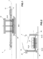
Figure 1 shows a longitudinal sectional view of an apparatus for cleaning the hull of a vessel according to an embodiment of the present invention; -
Figure 2 shows a cross-sectional view of the apparatus for cleaning the hull of a vessel ofFigure 1 ; -
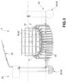
Figure 3 shows a cross-sectional view of the apparatus for cleaning the hull of a vessel ofFigure 1 , in working condition with maximum immersion; -
Figure 4 shows a cross-sectional view of the apparatus for cleaning the hull of a vessel ofFigure 1 , in navigation position; -
Figure 5 shows a longitudinal view of the apparatus for cleaning the hull of a vessel ofFigure 1 , in navigation position; -
Figure 6 shows a perspective view of a washing module of the apparatus for cleaning the hull of a vessel according to a possible embodiment of the present invention; -
Figures 7a-7b show a side and plan view, respectively, of a set of washing modules according to a possible embodiment of the present invention; -
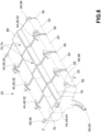
Figure 8 shows a plan view of washing modules according to a possible embodiment of the present invention; -
Figure 9 shows a sectional view of the washing modules ofFigure 8 , along the section plane IX-IX ofFigure 8 ; -
Figure 10 shows a sectional view of the washing modules ofFigure 9 , along the section plane X-X indicated inFigure 9 ; -
Figure 11 shows a sectional view of the washing modules ofFigure 8 , along the section plane XI-XI indicated inFigure 9 ; -
Figure 12 shows a plan view of the flexible seals of a washing module of the present invention; -
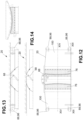
Figure 13 shows a sectional view of the module ofFigure 12 , along the section plane XIII-XIII ofFigure 12 ; -
Figure 14 shows a sectional view of the module ofFigure 12 , along the section plane XIV-XIV ofFigure 12 ; -
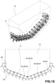
Figures 15-16 show perspective and front views of washing modules associated with vessels having different hull geometries; -
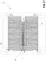
Figure 17 shows a plan view, in working position with minimum immersion, of the cleaning apparatus according to an embodiment of the present invention; -
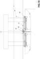
Figures 18-19 show sectional views, in working position with maximum immersion, of the cleaning apparatus according to possible embodiments of the present invention; -
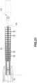
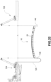
Figures 20-24 show sectional views of a cleaning apparatus according to a further embodiment of the present invention; -
Figure 25 shows a plan view of the apparatus ofFigures 20-24 ; -
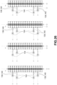
Figure 26 shows a plan view of the apparatus ofFigures 20-24 in successive steps of longitudinal advancement with respect to the hull. - Elements or parts of elements common to the embodiments described hereinafter will be indicated with the same numerical references.
- With reference to the aforesaid figures, the
reference numeral 4 globally indicates an apparatus for cleaning thehull 8 of avessel 12 according to the present invention. - It should be noted that for the purposes of the present invention the materials, dimensions and typology of the vessel and the hull are not relevant, even if, obviously, the invention has a preferred application to larger vessels. Furthermore, the invention finds application on vessels having one or more hulls (for example catamarans, trimarans and the like).
- The
apparatus 4 for cleaning thehull 8 of avessel 12 comprises awashing unit 16 having a plurality ofwashing modules 20 of saidhull 8, suitable for washing thehull 8 in a submerged configuration. - Furthermore, the
apparatus 4 comprises a service andguidance module 24 for thewashing unit 16, which acts as a support, movement and supply of means and services for saidwashing unit 16, as better described below. - According to a possible embodiment, said service and
guidance module 24 comprises a pair of longitudinal guides or supports 28, parallel to each other and to a main longitudinal extension direction Y-Y of thehull 8, so as to be able to guide and/or feed thewashing unit 16 during the movement thereof in said main longitudinal extension direction Y-Y. - Preferably, the service and
guidance module 24 is provided with propulsion means for moving the service andguidance module 24 and/or thewashing unit 16. - According to a possible embodiment, the service and
guidance module 24 comprises a turret equipped with at least one crane orwinch 32 for handling loads. - The service and
guidance module 24 is equipped with a dirty water storage tank 36, fluidically connected to thewashing modules 20 and containing the dirt removed from thehull 8 by thewashing modules 20. - Preferably, the service and
guidance module 24 is provided with a cleaning water storage tank 40, fluidically connected to thewashing modules 20 so as to feed pressurized cleaning water to thewashing modules 20. The washing pressure may reach up to about 200 bar. - According to a possible embodiment, the service and
guidance module 24 is a semi-submersible vessel module configured to position itself under thehull 8 of thevessel 12 to be cleaned. - Preferably, said semi-submersible vessel module comprises a pair of longitudinal submersed tanks, which serve as a dirty water storage tank 36 and cleaning water storage tank 40 so as to serve the washing means with which they are fluidically connected.
- As mentioned above, the service and
guidance module 24 is operatively connected to thewashing modules 20 which interface directly with thehull 8 of thevessel 12 for the relative cleaning. - In particular, according to a possible embodiment, the service and
guide module 24 comprises movement means 88 for thewashing modules 20. For example, said movement means 88 comprisevertical adjustment cables 26 and longitudinal and/ortransversal adjustment cables 27. - In particular, the
vertical adjustment cables 26 allow thewashing modules 20 to be moved along the vertical direction, so as to allow for example the sinking thereof under thehull 8 and subsequent lifting; the longitudinal and/ortransversal adjustment cables 27, on the other hand, allow thewashing modules 20 to be firmly fixed to thehull 8 both in the longitudinal direction Y-Y and in the transversal direction X-X. In this way, it is possible to firmly constrain thewashing modules 20 to the service andguidance module 24 and to the hull, preventing, for example the wave motion, from causing even violent impacts between thewashing modules 20 and thehull 8. At the same time, the longitudinal and/ortransversal adjustment cables 27 allow thewashing modules 20 to advance along the hull, in the longitudinal direction Y-Y, so as to allow the relative cleaning. Of course, both thevertical adjustment cables 26 and the longitudinal and/ortransversal adjustment cables 27 are operationally connected to relative drive winches and/or relative transmissions and drive mechanisms, preferably independent from each other so as to be able to carry out all the maneuvers of displacement and adaptation to the geometry of thehull 8 required by the circumstances and conditions of the sea. - Preferably, the sinking of the
washing modules 20 takes place with the aid ofsuitable ballasts 148. - According to a further embodiment, the service and
guidance module 24 comprises a first and asecond guide boat hull 8 to be cleaned, with respect to a transverse direction X-X. - Said first and
second guide boats first guide boat 124 comprises an umbilical 128 which distributes the pressurized washing water to thewashing modules 20. The umbilical 128 is preferably at least 10 m long and is a flexible tube so as to allow a correct safety spacing between thefirst guide boat 124 and thehull 8 to be cleaned. - Said
guide boats guide boats washing unit 16 with itswashing modules 20 under thehull 8 to be cleaned. - The
first boat 124, by means of the umbilical 128, may for example supply pressurized power and oil for the movement of thewashing modules 20. - The
second guide boat 126 is, for example, fluidically connected to thewashing modules 20 so as to be able to receive the so-called fouling, i.e. the water mixed with the dirt removed from thehull 8 which may be stored in aspecial tank 132. - Each of said
guide boats washing unit 16 in said direction during the cleaning of thehull 8. Of course, the advancement movement of theguide boats hull 8 along the main longitudinal extension direction Y-Y. - According to an embodiment, the
washing modules 20 are provided with means of advancement 136 so as to be able to advance longitudinally with respect to thehull 8. - For example, the means of advancement 136 comprise drive cylinders 140 fitted with a rod 142 which slides at least partially inside said drive cylinders 140 according to an actuation stroke, and at least one
electromagnet 144 to enable the means of advancement 136 to be anchored to a wall of thehull 8. - The
electromagnet 144, once activated, allows a solid anchoring to thehull 8 of thevessel 12; in this condition, the drive or the exit of the rod 142 from the respective drive cylinder 140 causes thewashing module 20 to advance by a stroke equal to at most the extraction stroke of the rod 142. - It is therefore sufficient to command the extraction or retraction of the rod 142 after anchoring the means of advancement 136 to the
hull 8 and connect the rod 142 to a portion of the washing modules to obtain the advancement of thewashing modules 20 along the longitudinal extension direction Y-Y with respect to thehull 8. - According to a further possible embodiment, the service and
guidance module 24 comprises aguide boat hull 8 to be cleaned, with respect to a transverse direction X-X. It is also possible to use two quays (for example in the case of a navigable canal) or two jetties as support points for the service andguidance module 24. - According to a further possible embodiment, the
vessel 12 is provided on board with said cleaningapparatus 4 which may be lowered at the moment of use by means of a crane supplied with thevessel 12 itself or which may also be kept immersed, for example in special housing formed inside thehull 8. - Advantageously, each
washing module 20 is equipped with mobile connection means 44 for the mobile mechanical connection of onewashing module 20 to anadjacent washing module 20, so as to allow a reciprocal movement between saidadjacent washing modules 20 during washing and/or movement. - Preferably, the
washing unit 16 comprises a plurality ofwashing modules 20 associated and arranged together in an arched pattern with an intrados counter-shaped with respect to thehull 8 of thevessel 12 to be cleaned. In other words, the mobile connection means 44, better described below, allow thewashing modules 20 to be adapted to the specific geometry, i.e. curvature, of thehull 8 to be cleaned. In fact, the individual washing modules constitute the segments of a broken curved line which is adapted and counter-shaped with respect to thehull 8. - According to a possible embodiment, said mobile connection means 44 comprise hinge means 48 for hinging
adjacent washing modules 20. - For example, the hinge means 48 comprise longitudinal hinges or pins 52 extending along a longitudinal rotation axis, parallel to a main longitudinal extension direction Y-Y of the associated
hull 8. - Preferably,
adjacent washing modules 20 compriseprofiles 56 at least partially flared and/or counter-shaped to each other at said mobile connection means 44, so as to allow reciprocal movement around said mobile connection means 44 to assume an arched configuration with an intrados counter-shaped with respect to thehull 8 of thevessel 12 to be cleaned. - Preferably, the mobile connection means 44 are arranged at upper ends 60 of the
washing module 20, directly facing the associatedhull 8. - According to a further embodiment, at least two
washing modules 20 comprise, as mobile connection means 44, vertical hinges or pins 64 extending along a vertical axis of rotation Z-Z, perpendicular to a plane tangential to thewashing module 20 and to thehull 8 to which thewashing module 20 is applied. The mobile connection means 44 may also comprise spherical hinges and/or cardan joints. - Preferably,
adjacent washing modules 20, provided with vertical hinges or pins 64, comprise at least partially flared and/orcounter-shaped profiles 56 so as to allow reciprocal rotation around said vertical hinges or pins 64. - Each
washing module 20 is in turn provided with washing means 68 of thehull 8 of avessel 12, suitable for scraping dirt from saidhull 8. - The washing means 68 may be of various types.
- For example, the washing means 68 comprise pressure water jets.
- Preferably, the washing means 68 are arranged at or astride a transverse center plane M-M of each
washing module 20, perpendicular to said main longitudinal extension direction Y-Y. - Preferably, each
washing module 20 comprises dirt collection means 72. - For example, the dirt collection means 72 comprise a collection chamber 74 delimited by sealing
means 76 arranged astride the washing means 20. - The sealing means 76, typically gaskets, serve to isolate the portion of the hull subject to the cleaning action of the washing means 68 so as to confine the dirt removed and prevent it from spreading in an uncontrolled manner.
- The washing means 68 may comprise a supply channel of pressurized
clean water 80 and a dirtywater recovery channel 84. - The dirty
water recovery channel 84 is in fluidic connection with the collection chamber 74. - Preferably, the supply channel of pressurized
clean water 80 is in fluidic connection with the cleaning water storage tank 40 of the service andguidance module 24. - Preferably, the dirty
water recovery channel 84 is in fluidic connection with the dirty water storage tank 36 of the service andguidance module 24. - According to a further embodiment, the washing means 68 comprise rotating brushes (not shown) which carry out cleaning by mechanical abrasion of the
hull 8. - The rotating brushes may be provided as an alternative or also alongside the jets of pressurized water.
- According to the invention, each
washing module 20 is provided with drive means 88 to allow the positioning and movement of thewashing module 20 with respect to thehull 8 and/or with respect toother washing modules 20 during the cleaning of thehull 8. - As mentioned above, movement means 88 comprising cables, tow ropes and the like are associated with said
washing modules 20 so as to allow thewashing modules 20 to be lifted and/or rotated around said mobile connection means 44. - Preferably, the movement means 88 comprise cables or tow ropes joined to each
washing module 20 at lower ends 92 of the module itself, opposite the associatedvessel 12 and said upper ends 60. - For example, the movement means 88 comprise contact and guide bearings 96 with the
hull 8, suitable to allow a reciprocal sliding between the module itself and thehull 8. - The contact and guide bearings 96 may comprise guide rollers with a transverse axis of rotation, perpendicular to the main longitudinal extension direction Y-Y of the
hull 8, so as to facilitate the sliding of thewashing module 20 on thehull 8 along said main longitudinal extension direction Y-Y. - Each
washing module 20 comprises at least onewatertight chamber 100, which may be filled with air, dimensioned so as to provide therelevant washing module 20 with a positive buoyancy thrust that allows it to be stopped in abutment against thehull 8 of the associatedvessel 12. - Preferably, the at least one
watertight chamber 100 is arranged astride the washing means 68 of eachwashing module 20, or adjacent thereto. - According to the invention, said
watertight chamber 100 is equipped with control means suitable to allow the at least partial flooding of thewatertight chamber 100 or the relative expulsion of water from saidwatertight chamber 100. In this way, it is possible to modify the overall buoyancy of thewashing module 20 according to the required needs. - The operation or the cleaning method carried out by a cleaning apparatus according to the present invention will now be described.
- In particular, the
washing unit 16 is initially sunk so that it may be positioned under thehull 8 of thevessel 12. - The vessel is anchored or moored beforehand, preferably on the stern side.
- The
washing unit 16 is then positioned resting on the hull, centered with respect to its own transverse center plane M-M. - According to a possible embodiment, the method proceeds by advancing from bow to stern. In this first step, the cleaning operation is not carried out, but a scan of the geometry/morphology of the
hull 8 and also of the degree, type and/or conformation of the dirt present on the hull itself. - Once at the stern, the
washing unit 16 goes back towards the bow, carrying out the actual cleaning. - The
washing unit 16 may also be provided with video cameras for recording in real time the cleaning operations, for example to allow an external operator to check the occurrence of possible problems. Of course, such shooting and alert operation may be automated. - The process described above obviously applies to any type of service and
guidance module 24 employed. - As seen, the cleaning of the
hull 8 is carried out keeping thewashing unit 16 at a constant distance from thehull 8 both in the vertical direction Z-Z, perpendicular to the waterline of thevessel 12, and in the transverse direction X-X perpendicular to the vertical direction Z-Z and the main longitudinal extension direction Y-Y of thevessel 8. - The method may also comprise the step of monitoring and controlling the position of the
washing unit 16 with respect to thehull 8 of thevessel 12 by means of position sensors and/or GPS and/or laser and/or ecoscanner technologies. - As may be seen from the above description, the cleaning apparatus according to the invention allows the drawbacks of the prior art to be overcome.
- In particular, the present invention allows cleaning of the hull to be carried out relatively quickly, without the use of divers.
- Cleaning is complete and effective and also does not involve any dispersion of the material detached from the hull, so it does not involve any environmental pollution.
- The cleaning operation does not cause any damage to the hull because the cleaning apparatus is relatively light and able to remain adherent to the hull without damaging it in any way, even in the event of wave motion. In fact, the washing modules are anchored to the hull in a vertical and transverse direction and are gradually towed in the longitudinal direction to clean the hull. In this way, even in the presence of wave motion, there are no dangerous collisions between the washing modules and the hull itself.
- Furthermore, the present invention provides for the implementation of an apparatus of considerably reduced dimensions and weights with respect to known solutions.
- By virtue of the fact that the dimensions and the weight are contained, the handling costs of the apparatus and the overall times of the cleaning operation are also reduced.
- Advantageously, the apparatus according to the present invention is capable of carrying out the cleaning of the boat even in the harbor, exploiting the waiting times of the vessel, such as, for example, waiting for passage in the Panama Canal. In this way, considerable time savings and cost optimization are achieved.
- Washing is carried out with pressurized water jets and the dirt collected directly by the
- washing modules and conveyed to a special collection chamber.
- A person skilled in the art may make several changes and adjustments to the cleaning apparatus and methods described above in order to meet specific and incidental needs, all falling within the scope of protection defined in the following claims.
Claims (14)
- Apparatus (4) for cleaning the hull (8) of a vessel (12) comprising a washing unit (16) having a plurality of washing modules (20) of said hull (8), suitable for washing the hull (8) in a submerged configuration,- wherein each washing module (20) is equipped with mobile connection means (44) for the mobile mechanical connection of one washing module (20) to an adjacent washing module (20), so as to allow a reciprocal movement between said adjacent washing modules (20) during washing and/or movement,- each washing module (20) having washing means (68) of the hull (8) suitable for scraping dirt from said hull (8),- each washing module (20) being equipped with drive means (88) to allow the positioning and movement of the washing module (20) with respect to the hull (8) and/or with respect to other washing modules (20) during the cleaning of the hull (8),characterised in thateach washing module (20) comprises at least one watertight chamber (100), which can be filled with air, dimensioned so as to provide the relevant washing module (20) with a positive buoyancy thrust that allows it to be stopped in abutment against the hull (8) of the associated vessel (12),and in that said watertight chamber (100) is equipped with control means suitable to allow the at least partial flooding of the watertight chamber (100) or expulsion of water from the watertight chamber (100).
- The apparatus (4) for cleaning the hull (8) of a vessel (12) according to claim 1, wherein the washing unit (16) comprises a plurality of washing modules (20) associated and arranged in an arched pattern with an intrados counter-shaped with respect to the hull (8) of the vessel (12) to be cleaned.
- The apparatus (4) for cleaning the hull (8) of a vessel (12) according to claim 1 or 2, wherein said mobile connection means (44) comprise hinged means (48) for hinging adjacent washing modules (20).
- The apparatus (4) for cleaning the hull (8) of a vessel (12) according to claim 3, wherein said hinged means (48) comprise longitudinal hinges or pins (52) extending along a longitudinal rotation axis, parallel to a main longitudinal extension direction (Y-Y) of the associated hull (8).
- The apparatus (4) for cleaning the hull (8) of a vessel (12) according to claim 1, 2, 3 or 4, wherein adjacent washing modules (20) comprise profiles at least partially flared and/or counter-shaped to each other at said mobile connection means (44), so as to allow reciprocal movement around said mobile connection means (44) to assume a straight and/or curved arched configuration with an intrados counter-shaped with respect to the hull (8) of the vessel (12) to be cleaned.
- The apparatus (4) for cleaning the hull (8) of a vessel (12) according to any of the claims from 1 to 5, wherein at least two washing modules (20) comprise, as mobile connection means (44), vertical hinges or pins (64) extending along a vertical axis of rotation, perpendicular to a plane tangential to the washing module (20) and to the hull (8) to which the washing module (20) is applied.
- The apparatus (4) for cleaning the hull (8) of a vessel (12) according to claim 6, wherein adjacent washing modules (20) with vertical hinges or pins (64) comprise profiles (56) at least partially flared and/or counter-shaped to each other so as to allow reciprocal rotation between the washing modules (20) around said vertical hinges or pins (64).
- The apparatus (4) for cleaning the hull (8) of a vessel (12) according to any of claims 1 to 7, wherein said movement means (88) comprise contact and guide bearings (96) with the hull (8), allowing a reciprocal sliding between the cleaning module itself (20) and the hull (8).
- The apparatus (4) for cleaning the hull (8) of a vessel (12) according to any of the claims from 1 to 8, wherein the washing means (68) comprise pressure water jets.
- The apparatus (4) for cleaning the hull (8) of a vessel (12) according to any of the claims from 1 to 9, wherein each washing module (20) comprises dirt collection means (72).
- The apparatus (4) for cleaning the hull (8) of a vessel (12) according to claim 10, wherein the dirt collection means (72) comprise a collection chamber (74) delimited by sealing means (76) arranged astride the washing means (68).
- The apparatus (4) for cleaning the hull (8) of a vessel (12) according to any of the claims from 1 to 11, wherein the washing means (68) comprise a supply channel of pressurized clean water (80) and a dirty water recovery channel (84).
- The apparatus (4) for cleaning the hull (8) of a vessel (12) according to claim 12 in combination with claim 11, wherein the dirty water recovery channel (84) is in fluidic connection with the collection chamber (74) .
- Method for cleaning the hull (8) of a vessel (12) comprising the steps of:- providing a cleaning apparatus (4) according to any of the claims from 1 to 13,- bringing said cleaning apparatus (4) into contact with the hull (8) and proceeding with cleaning using said washing modules (20) brought into contact with the hull (8) beforehand,monitoring and controlling the position of the washing unit (16) with respect to the hull (8) of the vessel (12) by means of position sensors and/or gps and/or laser and/or ecoscanner technologies.
Applications Claiming Priority (2)
| Application Number | Priority Date | Filing Date | Title |
|---|---|---|---|
| IT202000024553 | 2020-10-19 | ||
| PCT/IB2021/059230 WO2022084787A1 (en) | 2020-10-19 | 2021-10-08 | Apparatus and method for cleaning the hull of a vessel |
Publications (3)
| Publication Number | Publication Date |
|---|---|
| EP4228961A1 EP4228961A1 (en) | 2023-08-23 |
| EP4228961B1 true EP4228961B1 (en) | 2025-02-26 |
| EP4228961C0 EP4228961C0 (en) | 2025-02-26 |
Family
ID=74141679
Family Applications (1)
| Application Number | Title | Priority Date | Filing Date |
|---|---|---|---|
| EP21791026.4A Active EP4228961B1 (en) | 2020-10-19 | 2021-10-08 | Apparatus and method for cleaning the hull of a vessel |
Country Status (6)
| Country | Link |
|---|---|
| US (1) | US12595029B2 (en) |
| EP (1) | EP4228961B1 (en) |
| KR (1) | KR20230091142A (en) |
| CN (1) | CN116648405A (en) |
| ES (1) | ES3015214T3 (en) |
| WO (1) | WO2022084787A1 (en) |
Families Citing this family (1)
| Publication number | Priority date | Publication date | Assignee | Title |
|---|---|---|---|---|
| CN118907336B (en) * | 2024-08-15 | 2025-02-28 | 武穴市长江船舶修造有限公司 | A cleaning machine for ship maintenance |
Family Cites Families (16)
| Publication number | Priority date | Publication date | Assignee | Title |
|---|---|---|---|---|
| US3227124A (en) * | 1964-02-24 | 1966-01-04 | Leonard W Campbell | Boat bottom cleaning apparatus |
| JPS52123100A (en) | 1976-04-09 | 1977-10-15 | Yoshihiro Yonahara | Device of cleaning outside of ship |
| US4102290A (en) * | 1976-06-04 | 1978-07-25 | David Weiss | Underwater bottom cleaning system and apparatus |
| US4843995A (en) | 1987-08-27 | 1989-07-04 | Eyvonne M. Bingham | Automatic boat bottom cleaner |
| SE9002020L (en) | 1990-06-06 | 1991-12-07 | Olle Engvall | BAATTVAETTSANORDNING |
| US5431122A (en) | 1991-05-29 | 1995-07-11 | Templet, Jr.; John A. | Apparatus for cleaning the submerged portion of ship hulls |
| US5222452A (en) * | 1992-06-15 | 1993-06-29 | Maloney Michael J | Boat hull cleaning apparatus |
| NL1010114C2 (en) * | 1998-09-16 | 2000-03-17 | Fratomex Holding B V | Automatic washing installation for hulls of floating vessels uses rotating brushes, water and compressed air |
| JP4711572B2 (en) | 2001-09-21 | 2011-06-29 | 新日鉄エンジニアリング株式会社 | Attachment removal device for floating body bottom |
| ITCZ20130019A1 (en) * | 2013-10-09 | 2015-04-10 | Impianti E Servizi Portuali Morace Srl | AUTOMATIC FAIRING SYSTEM OF BOATS AND ITS PROCEDURE |
| CN106697223A (en) * | 2015-11-15 | 2017-05-24 | 重庆申化船舶表面技术工程有限公司 | Marine organism growth prevention device for ship planking |
| US10342326B2 (en) * | 2016-06-06 | 2019-07-09 | Saudi Arabian Oil Company | Underwater marine growth brushing mechanism with passive self-adjust for curved surfaces |
| IT201700036975A1 (en) | 2017-04-04 | 2018-10-04 | Guido Bardelli | FLOATING AND HANDLING SYSTEM FOR WASHING AND CLEANING OF FAIRING SHIPS |
| US10562600B2 (en) | 2017-08-04 | 2020-02-18 | Justo Garcia Diaz | Machine for cleaning boat hulls in the water |
| DE202019003386U1 (en) | 2019-08-07 | 2019-09-30 | Michael Reineke | Apparatus for cleaning the outer surface of hulls of ships lying in water |
| CN211055346U (en) * | 2019-12-14 | 2020-07-21 | 青岛炬荣工程科技有限公司 | Hydraulic pressure ship scraper terminal removes auxiliary device |
-
2021
- 2021-10-08 KR KR1020237017075A patent/KR20230091142A/en active Pending
- 2021-10-08 EP EP21791026.4A patent/EP4228961B1/en active Active
- 2021-10-08 CN CN202180085740.8A patent/CN116648405A/en active Pending
- 2021-10-08 WO PCT/IB2021/059230 patent/WO2022084787A1/en not_active Ceased
- 2021-10-08 ES ES21791026T patent/ES3015214T3/en active Active
- 2021-10-08 US US18/249,554 patent/US12595029B2/en active Active
Also Published As
| Publication number | Publication date |
|---|---|
| US12595029B2 (en) | 2026-04-07 |
| EP4228961A1 (en) | 2023-08-23 |
| KR20230091142A (en) | 2023-06-22 |
| ES3015214T3 (en) | 2025-04-30 |
| WO2022084787A1 (en) | 2022-04-28 |
| US20230382503A1 (en) | 2023-11-30 |
| EP4228961C0 (en) | 2025-02-26 |
| CN116648405A (en) | 2023-08-25 |
Similar Documents
| Publication | Publication Date | Title |
|---|---|---|
| WO2022084788A1 (en) | Apparatus and method for cleaning the hull of a vessel | |
| EP0559806B1 (en) | Watercraft hull modification | |
| US6688248B2 (en) | Submersible catamaran | |
| CA2929063C (en) | Marine lifting vessel | |
| US7451717B1 (en) | Systems and processes for covering openings of marine vessel hulls | |
| US5749758A (en) | Vessel for production and/or loading/unloading and transport of hydrocarbons from offshore fields, and/or for carrying out well operations | |
| US5549070A (en) | In-water dry dock system | |
| US20030140837A1 (en) | Transporting a ship over shallows of a watercoruse | |
| CN101475046B (en) | Large-sized thruster underwater installing process based on L type floating platform | |
| CN115653002B (en) | Long-distance underwater transportation method for immersed tube | |
| US12595029B2 (en) | Apparatus and method for cleaning the hull of a vessel | |
| WO2019000757A1 (en) | METHOD FOR ADDING WATER DURING SHIP ALLOWANCE | |
| WO2020035887A1 (en) | Plant with improved washing unit for washing and cleaning the hulls of ships | |
| KR20170129991A (en) | Management robot for mooring line | |
| CA2900357C (en) | An integrated heavy lift and logistics vessel | |
| JPH0986485A (en) | Manufacturing and repair work methods for large structures as well as barges used to implement these methods. | |
| KR101453740B1 (en) | Floating Watercraft Lift Apparatus For Raising Or Lowering The Watercraft | |
| KR101453741B1 (en) | Hydraulic Cylinder-Operated Floating Watercraft Lift Apparatus For Raising Or Lowering The Watercraft | |
| KR101768976B1 (en) | Hydraulic Cylinder-Operated Floating The Watercraft Lift Apparatus For Vertically Raising Or Lowering The Watercraft With The Frames Being Laid In The Floats | |
| KR101497397B1 (en) | A vessel with retractable thruster | |
| WO2022180478A1 (en) | Apparatus for cleaning a hull of a vessel | |
| CN110789688A (en) | Floating dock for maintaining movable ship plate and method for maintaining ship bottom plate | |
| KR101701287B1 (en) | Method for attaching and detaching sub-structure of drilling rig using cofferdam | |
| EP1492699B1 (en) | Submersible watercraft | |
| US4341174A (en) | Bow dock |
Legal Events
| Date | Code | Title | Description |
|---|---|---|---|
| STAA | Information on the status of an ep patent application or granted ep patent |
Free format text: STATUS: UNKNOWN |
|
| STAA | Information on the status of an ep patent application or granted ep patent |
Free format text: STATUS: THE INTERNATIONAL PUBLICATION HAS BEEN MADE |
|
| PUAI | Public reference made under article 153(3) epc to a published international application that has entered the european phase |
Free format text: ORIGINAL CODE: 0009012 |
|
| STAA | Information on the status of an ep patent application or granted ep patent |
Free format text: STATUS: REQUEST FOR EXAMINATION WAS MADE |
|
| 17P | Request for examination filed |
Effective date: 20230503 |
|
| AK | Designated contracting states |
Kind code of ref document: A1 Designated state(s): AL AT BE BG CH CY CZ DE DK EE ES FI FR GB GR HR HU IE IS IT LI LT LU LV MC MK MT NL NO PL PT RO RS SE SI SK SM TR |
|
| DAV | Request for validation of the european patent (deleted) | ||
| DAX | Request for extension of the european patent (deleted) | ||
| STAA | Information on the status of an ep patent application or granted ep patent |
Free format text: STATUS: EXAMINATION IS IN PROGRESS |
|
| 17Q | First examination report despatched |
Effective date: 20240626 |
|
| GRAP | Despatch of communication of intention to grant a patent |
Free format text: ORIGINAL CODE: EPIDOSNIGR1 |
|
| STAA | Information on the status of an ep patent application or granted ep patent |
Free format text: STATUS: GRANT OF PATENT IS INTENDED |
|
| INTG | Intention to grant announced |
Effective date: 20241125 |
|
| GRAS | Grant fee paid |
Free format text: ORIGINAL CODE: EPIDOSNIGR3 |
|
| GRAA | (expected) grant |
Free format text: ORIGINAL CODE: 0009210 |
|
| STAA | Information on the status of an ep patent application or granted ep patent |
Free format text: STATUS: THE PATENT HAS BEEN GRANTED |
|
| AK | Designated contracting states |
Kind code of ref document: B1 Designated state(s): AL AT BE BG CH CY CZ DE DK EE ES FI FR GB GR HR HU IE IS IT LI LT LU LV MC MK MT NL NO PL PT RO RS SE SI SK SM TR |
|
| REG | Reference to a national code |
Ref country code: GB Ref legal event code: FG4D |
|
| REG | Reference to a national code |
Ref country code: CH Ref legal event code: EP |
|
| REG | Reference to a national code |
Ref country code: DE Ref legal event code: R096 Ref document number: 602021026851 Country of ref document: DE |
|
| REG | Reference to a national code |
Ref country code: IE Ref legal event code: FG4D |
|
| U01 | Request for unitary effect filed |
Effective date: 20250226 |
|
| U07 | Unitary effect registered |
Designated state(s): AT BE BG DE DK EE FI FR IT LT LU LV MT NL PT RO SE SI Effective date: 20250306 |
|
| REG | Reference to a national code |
Ref country code: ES Ref legal event code: FG2A Ref document number: 3015214 Country of ref document: ES Kind code of ref document: T3 Effective date: 20250430 |
|
| REG | Reference to a national code |
Ref country code: GR Ref legal event code: EP Ref document number: 20250400641 Country of ref document: GR Effective date: 20250514 |
|
| PG25 | Lapsed in a contracting state [announced via postgrant information from national office to epo] |
Ref country code: RS Free format text: LAPSE BECAUSE OF FAILURE TO SUBMIT A TRANSLATION OF THE DESCRIPTION OR TO PAY THE FEE WITHIN THE PRESCRIBED TIME-LIMIT Effective date: 20250526 |
|
| PG25 | Lapsed in a contracting state [announced via postgrant information from national office to epo] |
Ref country code: PL Free format text: LAPSE BECAUSE OF FAILURE TO SUBMIT A TRANSLATION OF THE DESCRIPTION OR TO PAY THE FEE WITHIN THE PRESCRIBED TIME-LIMIT Effective date: 20250226 |
|
| PG25 | Lapsed in a contracting state [announced via postgrant information from national office to epo] |
Ref country code: IS Free format text: LAPSE BECAUSE OF FAILURE TO SUBMIT A TRANSLATION OF THE DESCRIPTION OR TO PAY THE FEE WITHIN THE PRESCRIBED TIME-LIMIT Effective date: 20250626 Ref country code: NO Free format text: LAPSE BECAUSE OF FAILURE TO SUBMIT A TRANSLATION OF THE DESCRIPTION OR TO PAY THE FEE WITHIN THE PRESCRIBED TIME-LIMIT Effective date: 20250526 |
|
| PG25 | Lapsed in a contracting state [announced via postgrant information from national office to epo] |
Ref country code: HR Free format text: LAPSE BECAUSE OF FAILURE TO SUBMIT A TRANSLATION OF THE DESCRIPTION OR TO PAY THE FEE WITHIN THE PRESCRIBED TIME-LIMIT Effective date: 20250226 |
|
| U20 | Renewal fee for the european patent with unitary effect paid |
Year of fee payment: 5 Effective date: 20250825 |
|
| PG25 | Lapsed in a contracting state [announced via postgrant information from national office to epo] |
Ref country code: SM Free format text: LAPSE BECAUSE OF FAILURE TO SUBMIT A TRANSLATION OF THE DESCRIPTION OR TO PAY THE FEE WITHIN THE PRESCRIBED TIME-LIMIT Effective date: 20250226 |
|
| PGFP | Annual fee paid to national office [announced via postgrant information from national office to epo] |
Ref country code: TR Payment date: 20250929 Year of fee payment: 5 |
|
| PG25 | Lapsed in a contracting state [announced via postgrant information from national office to epo] |
Ref country code: CZ Free format text: LAPSE BECAUSE OF FAILURE TO SUBMIT A TRANSLATION OF THE DESCRIPTION OR TO PAY THE FEE WITHIN THE PRESCRIBED TIME-LIMIT Effective date: 20250226 |
|
| PG25 | Lapsed in a contracting state [announced via postgrant information from national office to epo] |
Ref country code: SK Free format text: LAPSE BECAUSE OF FAILURE TO SUBMIT A TRANSLATION OF THE DESCRIPTION OR TO PAY THE FEE WITHIN THE PRESCRIBED TIME-LIMIT Effective date: 20250226 |
|
| PLBE | No opposition filed within time limit |
Free format text: ORIGINAL CODE: 0009261 |
|
| STAA | Information on the status of an ep patent application or granted ep patent |
Free format text: STATUS: NO OPPOSITION FILED WITHIN TIME LIMIT |
|
| PGFP | Annual fee paid to national office [announced via postgrant information from national office to epo] |
Ref country code: GB Payment date: 20251022 Year of fee payment: 5 |
|
| PGFP | Annual fee paid to national office [announced via postgrant information from national office to epo] |
Ref country code: GR Payment date: 20251022 Year of fee payment: 5 |
|
| PGFP | Annual fee paid to national office [announced via postgrant information from national office to epo] |
Ref country code: ES Payment date: 20251103 Year of fee payment: 5 |
|
| 26N | No opposition filed |
Effective date: 20251127 |