EP4228942B1 - A brake pressure modulator, pneumatic brake system and vehicle - Google Patents
A brake pressure modulator, pneumatic brake system and vehicle Download PDFInfo
- Publication number
- EP4228942B1 EP4228942B1 EP20792966.2A EP20792966A EP4228942B1 EP 4228942 B1 EP4228942 B1 EP 4228942B1 EP 20792966 A EP20792966 A EP 20792966A EP 4228942 B1 EP4228942 B1 EP 4228942B1
- Authority
- EP
- European Patent Office
- Prior art keywords
- valve
- pressure
- brake
- primary
- control
- Prior art date
- Legal status (The legal status is an assumption and is not a legal conclusion. Google has not performed a legal analysis and makes no representation as to the accuracy of the status listed.)
- Active
Links
Images





Classifications
-
- B—PERFORMING OPERATIONS; TRANSPORTING
- B60—VEHICLES IN GENERAL
- B60T—VEHICLE BRAKE CONTROL SYSTEMS OR PARTS THEREOF; BRAKE CONTROL SYSTEMS OR PARTS THEREOF, IN GENERAL; ARRANGEMENT OF BRAKING ELEMENTS ON VEHICLES IN GENERAL; PORTABLE DEVICES FOR PREVENTING UNWANTED MOVEMENT OF VEHICLES; VEHICLE MODIFICATIONS TO FACILITATE COOLING OF BRAKES
- B60T13/00—Transmitting braking action from initiating means to ultimate brake actuator with power assistance or drive; Brake systems incorporating such transmitting means, e.g. air-pressure brake systems
- B60T13/10—Transmitting braking action from initiating means to ultimate brake actuator with power assistance or drive; Brake systems incorporating such transmitting means, e.g. air-pressure brake systems with fluid assistance, drive, or release
- B60T13/24—Transmitting braking action from initiating means to ultimate brake actuator with power assistance or drive; Brake systems incorporating such transmitting means, e.g. air-pressure brake systems with fluid assistance, drive, or release the fluid being gaseous
- B60T13/26—Compressed-air systems
-
- B—PERFORMING OPERATIONS; TRANSPORTING
- B60—VEHICLES IN GENERAL
- B60T—VEHICLE BRAKE CONTROL SYSTEMS OR PARTS THEREOF; BRAKE CONTROL SYSTEMS OR PARTS THEREOF, IN GENERAL; ARRANGEMENT OF BRAKING ELEMENTS ON VEHICLES IN GENERAL; PORTABLE DEVICES FOR PREVENTING UNWANTED MOVEMENT OF VEHICLES; VEHICLE MODIFICATIONS TO FACILITATE COOLING OF BRAKES
- B60T13/00—Transmitting braking action from initiating means to ultimate brake actuator with power assistance or drive; Brake systems incorporating such transmitting means, e.g. air-pressure brake systems
- B60T13/10—Transmitting braking action from initiating means to ultimate brake actuator with power assistance or drive; Brake systems incorporating such transmitting means, e.g. air-pressure brake systems with fluid assistance, drive, or release
- B60T13/66—Electrical control in fluid-pressure brake systems
- B60T13/68—Electrical control in fluid-pressure brake systems by electrically-controlled valves
- B60T13/683—Electrical control in fluid-pressure brake systems by electrically-controlled valves in pneumatic systems or parts thereof
-
- B—PERFORMING OPERATIONS; TRANSPORTING
- B60—VEHICLES IN GENERAL
- B60T—VEHICLE BRAKE CONTROL SYSTEMS OR PARTS THEREOF; BRAKE CONTROL SYSTEMS OR PARTS THEREOF, IN GENERAL; ARRANGEMENT OF BRAKING ELEMENTS ON VEHICLES IN GENERAL; PORTABLE DEVICES FOR PREVENTING UNWANTED MOVEMENT OF VEHICLES; VEHICLE MODIFICATIONS TO FACILITATE COOLING OF BRAKES
- B60T8/00—Arrangements for adjusting wheel-braking force to meet varying vehicular or ground-surface conditions, e.g. limiting or varying distribution of braking force
- B60T8/32—Arrangements for adjusting wheel-braking force to meet varying vehicular or ground-surface conditions, e.g. limiting or varying distribution of braking force responsive to a speed condition, e.g. acceleration or deceleration
- B60T8/321—Arrangements for adjusting wheel-braking force to meet varying vehicular or ground-surface conditions, e.g. limiting or varying distribution of braking force responsive to a speed condition, e.g. acceleration or deceleration deceleration
- B60T8/3255—Systems in which the braking action is dependent on brake pedal data
- B60T8/327—Pneumatic systems
-
- B—PERFORMING OPERATIONS; TRANSPORTING
- B60—VEHICLES IN GENERAL
- B60T—VEHICLE BRAKE CONTROL SYSTEMS OR PARTS THEREOF; BRAKE CONTROL SYSTEMS OR PARTS THEREOF, IN GENERAL; ARRANGEMENT OF BRAKING ELEMENTS ON VEHICLES IN GENERAL; PORTABLE DEVICES FOR PREVENTING UNWANTED MOVEMENT OF VEHICLES; VEHICLE MODIFICATIONS TO FACILITATE COOLING OF BRAKES
- B60T17/00—Component parts, details, or accessories of power brake systems not covered by groups B60T8/00, B60T13/00 or B60T15/00, or presenting other characteristic features
- B60T17/18—Safety devices; Monitoring
- B60T17/22—Devices for monitoring or checking brake systems; Signal devices
- B60T17/221—Procedure or apparatus for checking or keeping in a correct functioning condition of brake systems
Definitions
- the modification involves installing a primary and a secondary relay control valve and, respectively on a pneumatic relay control line, connecting a supplementary reservoir and a two-way valve.
- the two-way valve or double check valve is located between a dummy reservoir and a relay valve and also connects the supplementary reservoir to the relay valve through the primary solenoid valve.
- US9796365B2 discloses an electronic-pneumatic braking system for a vehicle, for example for a heavy goods vehicle or an articulated truck, includes a TCS/ESC modulator, enabling control functions for a traction control system (TCS) and a vehicle stability control system.
- the TCS/ESC modulator includes a pneumatic relay valve, a solenoid valve and a changeover valve device.
- valve chamber 305 provides a spool chamber 305V and a spring chamber 305S, wherein the valve chamber 305 provides an empty and/or hollow spring chamber 305S, in particular wherein a spring space 305SR of the valve chamber 305 is free of a spring 321.
- the coil chamber 306 is empty and/or hollow, in particular wherein the coil chamber 306 provides a coil space 306C, which is free of a coil or the like solenoid 311 (thus indicated in fading dashed lines; which means that the coil space 306C has no solenoid 311).
- each of two solenoid controlled 2/2 direction control valves 208, 210 within brake pressure modulator 110 or 106 is same as the spatial requirement of double sided check valve 206.
Landscapes
- Engineering & Computer Science (AREA)
- Transportation (AREA)
- Mechanical Engineering (AREA)
- Braking Systems And Boosters (AREA)
- Regulating Braking Force (AREA)
- Valves And Accessory Devices For Braking Systems (AREA)
Description
- The present invention relates to a brake pressure modulator according to the preamble part of
claim 1 for a pneumatic brake system and/or for a vehicle. The invention also relates to a respective pneumatic brake system and/or a vehicle. - Such kind of brake pressure modulator comprises
- a relay valve for controlling a supply of pressurized air from a primary source to at least one brake actuator;
- a first valve sub-unit configured to be electronically actuated, wherein the first valve sub-unit is configured to receive a primary control pressure from the primary source intended for opening the relay valve; and
- a second valve unit configured
- to at least receive a secondary control pressure from a secondary source and at least part of the primary control pressure from the primary source and
- to transmit either the primary control pressure or the secondary control pressure to the relay valve, wherein
- when the secondary control pressure is transmitted to the relay valve, the primary control pressure from the primary source is disconnected, and/or when the primary control pressure is transmitted to the relay valve, the secondary control pressure from the secondary source is disconnected.
- More particularly, the present invention relates to the brake pressure modulator operable by a pneumatic force that operates as, for example, a multi-relay valve for wheel end actuators associated with a pneumatic brake system.
- For instance, the brake pressure modulator of the present invention can be a pneumatic brake pressure modulator (PCV unit section, pressure control valve unit section) that is provided at either a front and/or auxiliary axle of the vehicle (AVP, axle valve package) or associated with applying control pressure for the trailer brake system.
- Electronic brake systems allow precisely controllable and rapid braking of a vehicle. In this context, the output signal of a brake signal transmitter, which depends on a deceleration demand of the driver, is passed to a control unit. In the control unit, the output signal of the brake signal transmitter can be modified additionally by driving safety systems, such as an antilock system, a traction control system or a system for electronic stability control. From this, the control unit produces control signals, which are passed to "brake pressure modulators", which control the supply of a pressure medium, generally compressed air in the case of utility vehicles, to the individual braking devices or brake cylinders in a manner specific to the wheel or axle-wise by means of electromagnetically actuable valve arrangements.
- In the event that said control unit fails, e.g. because the power supply thereof is interrupted, the electronic brake system generally has a redundant device associated with the service brake or the pressure control system in order to be able to bring the vehicle safely to a halt, even in this operating situation, by brake actuation. More particularly, the redundant device comprises a modulator (PCV, pressure control valve) operable merely by a pneumatic force; this is without the need and/or independent of an electronic control.
- However, the use of spatially and structurally separate brake pressure modulators for the individual pressure control circuits gives rise to a relatively large installation space requirement and manufacturing expense for air brake systems of the type described on light to medium-weight utility vehicles. Given this background
DE 10 2009 009 811 A1 discloses a dual-circuit brake pressure modulator for an electronic brake system of a vehicle. - Brake pressure modulators for controlling the pressurized airflow to the brake actuators associated with either a front axle or to the brake actuators associated with the trailer have been known in the art.
- For instance,
US patent publication US 2017/210365 further discloses a conventional brake pressure modulator provided for the purpose of the controlling the flow of the pressurized flowed to the brake actuators. This conventional brake pressure modulators discloses use of a number of 2/2 solenoid control valves to manage the supply of the pressurized air from a brake signal transmitter to open or close one or more relay valves. -
US5718486A relates to an electropneumatic brake system for motor vehicles, in which a pedal-operated braking power generator is provided which acts electrically upon an electronic control unit and feeds pneumatically into a pressure modulator which includes a proportional valve device and a reversing valve device. The pressure modulator is also controlled by desired electric value signals of the electronic control unit and is used for activating a valve device which modulates pressure mediums for the brake operation of the brake system. When the electric control fails, the pressure modulator operates redundantly.WO2006/122374A1 discloses an electronically controlled pneumatic (ECP) brake system which is retrofitted to or a modification of an existing relayed or non-relayed brake setup. The modification involves installing a primary and a secondary relay control valve and, respectively on a pneumatic relay control line, connecting a supplementary reservoir and a two-way valve. The two-way valve or double check valve is located between a dummy reservoir and a relay valve and also connects the supplementary reservoir to the relay valve through the primary solenoid valve.US9796365B2 - A conventional
brake pressure modulator 400 is also shown inFIG. 4 of the present application. This figure has also been clearly demarcated as 'prior art' in the drawings accompanying the present application. While the general functioning ofbrake pressure modulator 400 will be derivable to the person skilled in the art of the vehicle brake systems and from the above citedUS patent publication US 2017/210365 , it is nevertheless shortly (to the extent necessary) explained herewith. - As can be derived from
FIG. 4 , in order for servicebrake pressure inlet 410 to be connected with servicebrake pressure outlet 412 for pressure from reservoir II, arelay valve 402 should to be activated. In accordance with the conventionalbrake pressure modulator 400, a pneumatic pressure is applied for actuatingrelay valve 402 in order to selectively enable or disable such a connection betweeninlet 410 andoutlet 412. This control pressure is derived fromcontrol pressure inlet 408 receiving pressurized fluid from a reservoir via brake signal transmitter (BST). As can also be derived fromFIG. 4 , the activation ofrelay valve 402 is however dependent on receiving the control pressure supply from e.g., afirst valve unit 404 and/or asecond valve unit 406. Based on the activation states of first andsecond valve units relay valve 402. - It is noted that there are also default positions for first and
second valve units relay valve 402 almost one of the twovalve units valve units relay valve 402. The default positions of each of 2/2 solenoid valves provided in first andsecond valve units inlet 410 anoutlet 412 is established so that during emergency brake application scenarios, when the driver presses the brake pedal (not shown inFIG. 4 ), the control pressure is still supplied torelay valve 402 to be activated. Such solutions may be referred to as safety braking solutions and may for instance be sometimes stipulated by regulations. - For instance, UN-ECE Reg. No. 13, in the paragraph 5.2.1.18.3. provides one such requirement for trailer brakes in the situations, for instance, when an electric line is found to be defective.
- It follows from the above that
valve units valve units brake pressure modulator 400. Needless to say, this has direct effect on the cost of the product due to additional manufacturing and constructional costs that using electronically controlled solenoids entail, but at the same time complying with the safety requirements of the regulations. -
FIG. 5 shows a cross-sectional view of the conventionalbrake pressure modulator 400 where the location ofvalves valve units inlets - As can be noticed, three electronically
actuable valves modulator housing 502 ofbrake pressure modulator 400. As mentioned above, providing spatial allocation for threevalves - It follows from the above, one of the cost effective solutions is, for instance, to use a mechanically operable valve instead of solenoid valves, which can be found in e.g., the German application
DE 10 2018 122 193 A1 filed also by the Applicant of the present application. However, one of the challenges is the implementation of such an idea is the design constraints involved within the brake modulator when the mechanically operable valve is utilized and at the same time to achieve same function of the electronically operated valves. It is one of the objectives to reduce to the costs on wiring and other details of the brake pressure modulators such as conventionalbrake pressure modulator 400, but at the same time providing the same functionality as the electronically operated valves and complying with the spatial constraints within the brake pressure modulators. - It follows from the above section that the cost effective solution is not only in replacing e.g., the existing solenoid valve with a mechanical valve, but obtaining the same functionality using said mechanical valve taking the spatial constraints within the brake pressure modulators into account.
- The major object of the invention is to provide a preferred brake pressure modulator wherein said mechanically operable valve is established and integrated in the brake pressure modulator in an advantageous way observing the above conditions.
- This objective is achieved through the invention as claimed in
independent claim 1. - In accordance with an embodiment of the present invention, a brake pressure modulator is provided, wherein said modulator comprises a relay valve for controlling a supply of pressurized air from a primary source (II) to at least one brake actuator,
- a first valve sub-unit configured to be electronically actuated, wherein the first valve sub-unit is configured to receive a primary supply pressure form the primary source (II) as well as a connection to the ambient air for exhaust purposes, intended for controlling the relay valve, and
- a second valve unit configured to at least receive a secondary control pressure from a secondary source ('BST') and at least part of the primary control pressure from the primary source (II) and to transmit either the primary control pressure or the secondary control pressure to the relay valve, and wherein,
- when the secondary control pressure is transmitted to the relay valve, the primary control pressure from the primary source (II) is disconnected, and/or when the primary control pressure is transmitted to the relay valve, the secondary control pressure from the secondary source (BST) is disconnected.
- Furthermore, according to the invention the second valve unit is a mechanically operable valve in form of a pneumatically controlled valve having a valve casing, the valve casing comprising:
- a pressurized guiding sleeve providing a valve chamber configured to axially guide a pressure pickup piston or the like spool adapted for pneumatic actuation thereof, in particular adapted for mere pneumatic actuation thereof, and
- a coil casing configured to provide a coil chamber peripheral next to the pressurized guiding sleeve, wherein
- In essence, according to the inventive concept the pneumatically controlled valve uses the same components of the existing solenoid valve, but without the spring and electrical coil that is used to excite the spool and/or assist in retaining said spool in the excited position.
- One of the technical advantages of providing the mechanically operable valve for the second valve unit is, unlike the second valve unit of conventional brake modulators with electronically controlled solenoid valve, space for wirings and other hardware requirements associated with the solenoid valve are done away with. This has a direct effect on the cost of the product as well as makes the brake pressure modulator more self-reliant and not always dependent on electronic control. In this certain way, the redundant functioning (or functioning of the brake modulator without electronic control) is boosted at the same time satisfying the safety requirements of the pneumatic braking system. The pneumatically controlled valve enables a simple mechanism in which selective transmission of the brake pressure is taken care of as only one of pressure lines can be connected to the relay valve for its actuation and as a result, same control achieved due to the usage of solenoid valves is achieved using the pneumatically controlled valve
- The pneumatically controlled valve can be established as an "only" mechanically operable valve, this is more precisely "only" a mechanically-pneumatically operable valve. This means the mechanically-pneumatically operable valve switches without electrical or electro-magnetic aid.
- Apart from this, the mechanically-pneumatically operable valve can be established generally in any form advantageous way to be integrated in the brake pressure and configured to switch between a first and a second state when receiving a first and/or second switch-control pressure derived from the primary and/or secondary control pressure.
- The invention also leads to a pneumatic brake system of claim19 and a vehicle of claim 20 comprising the pneumatic brake system.
- The pneumatic brake system comprises:
the brake pressure modulator according to the invention or a development thereof; - a centralized pressure modulator connected to the brake pressure modulator, and
- a centralized electronic control unit mounted on the central axle control valve wherein the centralized electronic control unit transmits control signals to at least the first valve sub-unit.
- These and further developed configurations of the invention are further outlined in the dependent claims. The dependent claims provide further embodiments and associated technical advantages. Thereby, the mentioned advantages of the proposed concept are even more improved. For each feature of the dependent claims, it is claimed independent protection independent from all other features of this disclosure.
- In a preferred development the valve chamber provides a spool chamber and a spring chamber, wherein the valve chamber provides an empty and/or hollow spring chamber, in particular wherein a spring space of the valve chamber is free of a spring.
- In a preferred development, the coil chamber is empty and/or hollow, in particular wherein the coil chamber provides a coil space, which is free of a coil or the like solenoid.
- In a preferred development the pneumatically controlled valve is configured to switch between a first and a second state
- when receiving the primary and/or secondary control pressure, and/or
- when receiving a first and/or second switch-control pressure derived from the primary and/or secondary control pressure.
- In an exemplifying preferred first variant, which is described with preferred developments the mechanically-pneumatically operable valve switches when, receiving a first and/or second switch-control pressure against a spring force. In an exemplifying preferred second variant, which is described with preferred developments, the mechanically-pneumatically operable valve switches when receiving a first and/or second switch-control pressure against each other, thus in particular configured to selectively transmit the pressure of a higher magnitude among the primary and secondary control pressures received from the primary source (II) and the secondary source (BST), respectively.
- In a preferred development the pressurized guiding sleeve is configured to guide the pressure pickup piston or the like spool in a first position corresponding to the first state and in a second position corresponding to the second state, in particular wherein the first and second position of the spool are selected from positions on the valve seat and the spool stop respectively.
- In a preferred development, the valve chamber extends between a valve seat on a valve body and a spool stop on a first pressure-guiding casing path.
- In a preferred development
- a first pressure-guiding casing path provides a first pressurized path and a pressure pickup path, and/or
- the valve body is resided in a second pressure-guiding casing part providing a second pressurized path.
- In a preferred development
- the spool includes a rubber base at at least one side of the spool, and/or
- the valve body features a sealing ring.
- Furthermore, according to a first variant of development the pneumatically controlled valve is a double check valve, in particular wherein the double check valve is configured to switch between a first and a second state when receiving the primary and/or secondary control pressure. The double sided check valve is configured to selectively transmit the pressure of a higher magnitude among the primary and secondary control pressures received from the primary source (II) and the secondary source (BST), respectively.
- Furthermore, according to a second variant of development the second valve unit is a pneumatically controlled 3/2-directional valve that is configured to switch between a first and a second state when receiving a first and/or second switch-control pressure derived from the primary and/or secondary control pressure. More particularly the pneumatically controlled valve, in particular a 3/2-directional valve, is configured to switch from the second to the first state when receiving the first switch-control pressure derived from the primary control pressure such that the primary control pressure is transmitted to the relay valve. More particularly the pneumatically controlled valve, in particular a 3/2-directional valve, is configured to switch from the second to the first state when receiving the first switch-control pressure derived from the primary control pressure such that the primary control pressure is transmitted to the relay valve.
- In a particular preferred development, the pneumatically controlled 3/2-directional valve in the second state is adapted to transmit the secondary control pressure to the relay valve and in the first state is adapted to transmit the primary control pressure to the relay valve. These two states have been shown to be particular advantageous to be established in the pneumatically controlled 3-port/2-way-directional valve
- Thus, in a further particular preferred development the pneumatically controlled valve, in particular a double check valve or a 3/2-directional valve, is configured to switch from the second to the first state when receiving the first switch-control pressure derived from the primary control pressure such that the primary control pressure is transmitted to the relay valve. In particular, the pneumatically controlled 3/2-directional valve here is according to the above-mentioned first variant and switches a control pressure against a switch-control pressure.
- In a particular preferred development, the variants of a double check valve and a 3/2-directional valve can be combined, in particular preferably with omitting the need for a valve spring.
- Preferably therein the pneumatically controlled valve, in particular a double check valve or a 3/2-directional valve, is configured so as to selectively transmit the pressure of a higher magnitude among the primary and secondary control pressures received from the primary source (II) and the secondary source (BST), respectively. In particular, the pneumatically controlled valve here is according to the above-mentioned second variant and switches upon load by a first and a second switch-control pressure against each other. A respective piston loaded by a first switch-control pressure against a load of a second switch-control pressure of the piston is provided in the pneumatically controlled valve.
- In accordance with the same development as above, in which the brake pressure modulator is described, the pneumatically controlled valve, in particular a double check valve or a 3/2-directional valve, includes a spool with two opposing sides, wherein a first one among the two opposite sides receives the pressurized air from the primary source (II) and a second one among the two opposite sides receives the pressurized air from the secondary source (BST). The resulting configuration as provided in this development enables a mechanism that can translate the selective application through simple hardware means i.e., the spool configuration. The linear translation of the spool enables which supply of the pressurized air i.e., whether from the secondary source or from the primary source be given priority, based on the respective magnitude of the pressure.
- In accordance with one or more of the above developments, in which the brake pressure modulator is described, the pneumatically controlled valve, in particular a double check valve or a 3/2-directional valve, includes a casing which covers the spool, wherein the spool is configured to linearly translate within the casing, and wherein the direction of movement of the spool within the casing is directly dependent on a difference in the magnitude of the pressure received from primary source (II) and the secondary source (BST). It is one of the most advantageous developments of the present invention where the mechanically operable spool valve enables the Boolean operation of supplying the connection with a higher pressure air supply. The surface interaction between the spool and the casing enables realizing the simple mechanism of three ports, two position configuration direction control valve with minimal number of components.
- In the same or different development, in which the brake pressure modulator of the present invention is described, the first valve sub-unit is provided which includes two solenoid controlled 2/2 direction control valves and wherein, based on an actuation state of each of the two direction control valves, the brake pressure modulator is configured to perform one of the following functions:
- enabling the supply of the primary control pressure from the primary source (II) to actuate the relay valve;
- disabling or blocking the supply of the primary control pressure from the primary source (II) to the relay valve; and
- releasing the primary control pressure from the primary source (II) to the atmosphere, wherein the primary control pressure is intended for opening the relay valve. In combination with the simple mechanically operable valve, electronically or solenoid controlled direction valves configure the complex operation of connecting and/or venting the control pressure form the primary source such as reservoir II in a straight forward manner.
- In a development, in which the brake pressure modulator is described, the relay valve, the first valve sub-unit, and the second valve unit are encompassed within a single cast body of the brake pressure modulator. For an ease of manufacture, all the components are incorporated in a single cast unit. For instance, aluminum or cast iron could be used make the cast body of the brake pressure modulator.
- The brake pressure modulator of any one of the above developments, wherein the brake pressure modulator is for controlling supply of the pressurized air to the brake actuators associated with a front axle of a vehicle.
- The brake pressure modulator of any one of the above-discussed developments, wherein the brake pressure modulator is for controlling coupling head control pressure provided to the brake system of a vehicle trailer.
- In an development, a pneumatic brake system is disclosed which system comprises the brake pressure modulator one or more of the above discussed developments, a centralized pressure modulator connected to the brake pressure modulator, and a centralized electronic control unit mounted on the central axle control valve wherein the centralized electronic control unit transmits control signals to at least the first valve sub-unit. In another development, a vehicle comprising the pneumatic brake system is disclosed.
- For a more complete understanding of the invention, the invention will now be described in detail with reference to the accompanying drawing. The detailed description will illustrate and describe what is considered as a preferred embodiment of the invention. It should of course be understood that various modifications and changes in form or detail could readily be made without departing from the scope of the invention as claimed. It is intended that the invention may not be limited to the exact form and detail shown and described herein, nor to anything less than the whole of the invention disclosed herein and as claimed hereinafter. Further the features described in the description, the drawing and the claims disclosing the invention may be essential for the invention considered alone or in combination. In particular, any reference signs in the claims shall not be construed as limiting the scope of the invention. The wording "comprising" does not exclude other elements or steps. The wording "a" or "an" does not exclude a plurality. The wording, "a number of" items, comprises also the number one, i.e. a single item, and further numbers like two, three, four and so forth.
-
- FIG. 1
- illustrates a pneumatic brake system of a vehicle in accordance with an embodiment of the present invention;
- FIG. 2
- illustrates a brake pressure modulator with the mechanically operable valve in form of a pneumatically controlled double check valve in accordance with a prime preferred embodiment of the present invention;
- FIG. 2a
- illustrates a brake pressure modulator with the mechanically operable valve in form of a pneumatically controlled 3/2-directional valve in accordance with a first preferred embodiment of the present invention;
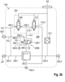
- FIG. 2b
- illustrates a brake pressure modulator with the mechanically operable valve in form of a pneumatically controlled 3/2-directional valve in accordance with a second preferred embodiment of the present invention;
- FIG. 2c
- illustrates a brake pressure modulator with the mechanically operable valve in form of a pneumatically controlled 3/2-directional valve in accordance with a third preferred embodiment of the present invention;
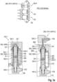
- FIG. 3a
- illustrates a mechanically operable valve (pressure control valve, PCV, in particular axle PCV (APCV)) in form of a pneumatically controlled valve of the brake pressure modulator as a PCV-unit-section for an axle valve package (AVP),
- in view (A) in a schematic view the position of the pressure control valve PCV for the brake pressure modulator as a PCV-unit-section and
- in view (C) as an embodiment of the invention in a cut out sectional view of the pneumatically controlled 3/2-directional valve as compared to an embodiment not belonging to the invention in view (B) of a conventional electro-magnetic controlled 3/2-directional valve;
- FIG. 3b
- the brake pressure modulator with a PCV unit section, wherein the axle PCV (APCV) as a preferred embodiment is shown in a cross-sectional view;
- FIG. 3c
- the brake pressure modulator of
FIG. 3a view (A) with the pressure control valve PCV in assembled form; - FIG. 3d
- the brake pressure modulator as a PCV-unit-section with a PCV, respectively a APCV (axle pressure control valve), in a perspective partly cut out view to the APCV (axle pressure control valve) which is used instead of an electronically actuable valve;
- FIG. 3e
- the brake pressure modulator in assembled form with the PCV of
FIG. 3b ; - FIG. 4
- illustrates a conventional brake pressure modulator of prior art with electronically actuable valves; and
- FIG. 5
- illustrates a cross-sectional view of the conventional brake pressure modulator of
Fig. 4 . - Further details and advantages of different components are explained in the detailed description provided below. The labeling of the elements of different drawings is not to be construed as limiting. The scope of the present invention is defined by one or more claims listed under 'claims' section.
- For identical or equivalent items or items of identical or equivalent function in the following, the some reference marks are used. For corresponding features, thus it is referred to the above description.
-
FIG. 1 illustrates apneumatic brake system 100 of a vehicle (not labeled) in accordance with an embodiment of the present invention. Alternatively, the vehicle (not labeled) includespneumatic brake system 100. -
Pneumatic brake system 100 in general includes a centralized (brake)pressure modulator 102, which is configured, inter alia, to receive a brake control input in the form of control pressure from a brake signal transmitter (labeled as 'BST' inFIG. 1 ) and in a preferred embodiment, to receive electronic signals from Electronic Stability Controller Module (ESCM) 102a connected to it via e.g. CAN (Controller Area Network) bus. In a further preferred embodiment,centralized pressure modulator 102 is also connected to a Power Line Carrier (PLC) 108 that is connected, for example, to a trailer (not shown infigure 1 ). It is noted that the driver of the vehicle actuates a brake pedal or BST to supply brake pressure towheel end actuators - In modern pneumatic brake systems such as the one shown in
FIG. 1 , the BST simply transmits an electronic signal using a stroke sensor (not shown inFIG. 1 ) to read a control output from a brake pedal (not shown inFIG. 1 ) to a central brake pressure modulator unit provided in combination withcentralized pressure modulator 102. Said stroke sensor (not shown inFIG. 1 ) is configured to read or determine the movement of a plunger as a result of the driver applying pressure on the brake pedal. - On receiving the control inputs from the BST,
centralized pressure modulator 102 transmits control pressure to the brake pressure modulators, in particular to the ones located at front axle 'FA' as well as to the brake pressure modulator assigned for trailer brakes. InFIG. 1 , the brake pressure modulator assigned for the front axle brakes is labeled as "110" and the brake pressure modulator assigned for the trailer brakes is labeled as "106". From the respective brake pressure modulators, the control pressure is transferred to respectivewheel end actuators - Furthermore, there different accumulators or reservoirs displayed in
FIG. 1 are for supplying pressurized air to different receivers present withinpneumatic brake system 100. For instance, reservoir 'I' is configured to supply pressurized air towheel end actuators brake pressure modulator 106. Reservoir 'II' is for supplying pressurized air to front axlebrake control modulator 110. -
Pneumatic brake system 100 of the present embodiment also additionally discloses wheel speed sensors WSS1, WSS2, WSS3 and WSS4 located at each of the wheels to determine their rotational speeds, a CAN network unit 114 (refers to a networking unit operating via CAN protocol), an on-board battery 116, and a steering angle sensor 118. The functioning of these components is not part of the present invention and therefore, no further explanation is provided in this regard. - Additionally,
pneumatic brake system 100 includes also park brake control unit denoted as -PB - inFIG. 1 . For instance, PB is connected to brakepressure modulator 104, which in accordance with an embodiment used for modulating parking brakes, and which is also associated with the spring brakes (or e.g., theactuators FIG. 1 ). - Further details of
brake pressure modulators 110 and/or 106 of the present invention are provided in the forthcoming sections. To the extent the subject-matter of the present invention relates to thebrake pressure modulator 110 associated with front axle FA of the vehicle, the underlying features of the claimed invention and the technical teaching associated with the brake pressure modulators provided at other parts ofpneumatic brake system 100, includingcentralized pressure modulator 102, trailerbrake pressure modulator 106 and exceptionally, rear axle pressure modulator orrelay valve 106. -
FIG. 2 ,FIG. 2a ,FIG. 2b andFIG. 2c each respectively in a scheme of circuit diagram illustrate abrake pressure modulator brake pressure modulator 110, 106 -in particular the front axlebrake control modulator 110 and/or a trailerbrakes pressure modulator 106-- shown inFIG. 1 . - As shown in each of
FIG. 2 ,FIG. 2a ,FIG. 2b andFIG. 2c thebrake pressure modulator relay valve 202 for controlling a supply of pressurized air from a primary source (II) to at least one brake actuator of 112a, 112b (seeFIG. 1 ). For instance, actuation ofrelay valve 202 enables connection between supply lines 202.1 and 202.2.Supply line 202. 1 is connected to reservoir 'II' (seeFIG. 1 ) whereas supply line 202.2 leads to Anti-lock Braking System valves ABS-1 and ABS-2 (seeFIG. 1 ) and consequently, towheel end actuators - However, in order to open and/or
close relay valve 202, typically, a control pressure is required. - As can be derived identical from each of
FIG. 2 ,FIG. 2a ,FIG. 2b andFIG. 2c this control pressure is received from asecond valve unit 206. Thesecond valve unit 206, in accordance with the present embodiments ofFIG. 2 ,FIG. 2a ,FIG. 2b andFIG. 2c , is a mechanically operable valve in form of a pneumatically controlled valve, also referred to withreference mark 206 for the second valve unit. - In turn, the
second valve unit 206 receives control pressure inputs from either of control input lines 206.1 and 206.2. In an exemplary embodiment, control input line 206.1, for instance, is connected to afirst valve sub-unit 204 whereas control input line 206.2 is connected to BST (seeFIG. 1 ). - The
second valve unit 206 is a mechanically operable valve, which will now be described below with regard toFIG. 2 in detail as a functioning like a pneumatically controlleddouble check valve 206D of thesecond valve unit 206. The description also holds forFIG. 2a ,FIG. 2b andFIG. 2c in principle; details and differences follow with explicit reference toFIG. 2a ,FIG. 2b andFIG. 2c . - In accordance with the present embodiment --exemplary with regard to
FIG. 2 --first valve sub-unit 204 is configured to be electronically actuated, whereinfirst valve sub-unit 204 is configured to receive a primary control pressure Pc1 from the primary source such as reservoir 'II' intended for openingrelay valve 202. For instance, see e.g. reference sign 202.3 where connection to reservoir II is shown to bifurcate, wherein one leads to supply line 202.1 and another leads to port 208.1 of a first solenoid controlled 2/2direction control valve 208 offirst valve sub-unit 204. - Further, in accordance with the same embodiment, the
second valve unit 206 is a mechanically operable valve. It is configured to at least receive a secondary control pressure Pc2 from a secondary source ( such as 'BST' ofFIG. 1 ) and at least part of the primary control pressure Pc1 from the primary source (such as reservoir 'II' ofFIG. 1 ) and to transmit either the primary control pressure Pc1 or the secondary control pressure Pc2 to therelay valve 202. This is in particular for activation of therelay valve 202 to e.g., open, and wherein, when the secondary control pressure is transmitted to therelay valve 202, the primary control pressure from the primary source (such as reservoir 'II' ofFIG. 1 ) is disconnected and/or when the primary control pressure is transmitted to therelay valve 202, the secondary control pressure from the secondary source (BST) is disconnected. - In accordance with this preferred embodiment, it should be noted that the
second valve unit 206 receives at least part of the primary control pressure Pc1 from the primary source via thefirst valve sub-unit 204. - In accordance with the present embodiment, the
first valve sub-unit 204 includes two solenoid controlled 2/2direction control valves direction control valves brake pressure modulator 110a is configured to perform one of the following functions: - enabling the supply of the primary control pressure from the primary source (II) to actuate
relay valve 202; - disabling or blocking the supply of the primary control pressure from the primary source (II) to
relay valve 202; and - releasing the primary control pressure from the primary source (II) to the atmosphere, wherein the primary control pressure is intended for opening
relay valve 202. - The prime preferred embodiment of
FIG. 2 provides a mechanically operable valve, which is functioning like and -in this embodiment-- is formed as a pneumatically controlleddouble check valve 206D; the structure is advantageously integrated in the brake pressure modulator as will be further elucidated with regard toFIG. 3a to FIG. 3e . - The mechanically operable valve according to another first, second and third embodiment of the
second valve unit 206 will be described below with regard toFIG. 2a ,FIG. 2b andFIG. 2c in detail. Namely in these further embodiments the mechanically operable valve is a pneumatically controlled 3/2-directional valve that is configured to switch between a first and a second state when receiving a first and/or second switch-control pressure P1, P2 derived from the above mentioned primary and/or secondary control pressure Pc1, Pc2; at least the embodiment ofFIG. 2c is operated in a preferred nearest analogy to the prime preferred embodiment of a pneumatically controlleddouble check valve 206D inFIG. 2 . - In
FIG. 2a ,FIG. 2b andFIG. 2c respectively each embodiment features a pneumatically controlled 3/2-directional valve FIG. 2a ,FIG. 2b andFIG. 2c ) it is adapted to transmit the secondary control pressure Pc2 to therelay valve 202 and in the first state it is adapted to transmit the primary control pressure Pc1 to therelay valve 202. These two states have been shown to be particular advantageous to be established in the pneumatically controlled 3-port/2-way-directional valve - Like the
double check valve 206D inFIG. 2 , as described above, the pneumatically controlled 3/2-directional valve FIG. 2a ,FIG. 2b ,FIG. 2c the mechanically-pneumatically operable valve is established in form of the pneumatically controlled 3/2-directional valve FIG.2a , Fl.2b,FIG.2c . This being said, at least the embodiment of the pneumatically controlled 3/2-directional valve 206C ofFIG. 2c is operated in nearest analogy to the prime embodiment of a pneumatically controlleddouble check valve 206D. The "only" mechanically operable valve replaces an electro-magnetic actuable pneumatic valve of the valve unit with electronicallyactuable valve 406 shown inFIG. 4 andFIG. 5 . - The mechanically operable valve -in particular the
double check valve 206D inFIG. 2 or the pneumatically controlled 3/2-directional valve brake pressure modulator FIG. 3a to FIG. 3e . - In an exemplifying preferred first variant, which is described with the embodiments of
FIG. 2a andFIG.2b the mechanically-pneumatically operable valve in form of the pneumatically controlled 3/2-directional valve - In the first preferred embodiment of
FIG. 2a the pneumatically controlled 3/2-directional valve 206A is configured to switch from the second state "2" to the first state "1" when receiving the first switch-control pressure P1 in switch-control line 206.4 derived from the primary control pressure Pc1 such that the primary control pressure Pc1 from control input line 206.1 is transmitted to therelay valve 202 via control output line 206.3. In particular, the pneumatically controlled 3/2-directional valve here is according to the above-mentioned first variant and switches against a secondary control pressure Pc2. A respective piston 206.6 loaded by a first switch-control pressure P1 against a secondary control pressure Pc2 load of the piston 206.6 is provided in the pneumatically controlled 3/2-directional valve. The piston is pressure loaded with first switch-control pressure P1 via a respective pressure port 206.7. - In the second preferred embodiment of
FIG. 2b the pneumatically controlled 3/2-directional valve 206B is configured to switch from the first state "1" to the second state "2" when receiving the second switch-control pressure P2 in switch-control line 206.4 derived from the secondary control pressure Pc2 such that the secondary control pressure Pc2 from control input line 206.2 is transmitted to therelay valve 202 via control output line 206.3. In particular, the pneumatically controlled 3/2-directional valve here is according to the above-mentioned first variant and switches against a primary control pressure Pc1. A respective piston 206.6 loaded by second switch-control pressure P2 against a primary control pressure Pc1 load of the piston 206.6 is provided in the pneumatically controlled 3/2-directional valve. The piston is pressure loaded with second switch-control pressure P2 via a respective pressure port 206.7. - In an exemplifying third preferred embodiment of a second variant, which is described with the embodiment of
FIG. 2c , the mechanically-pneumaticallyoperable valve 206C--without a spring-- switches when receiving a first and/or second switch-control pressure P1, P2 against each other. Thus in particular it is configured to selectively transmit the pressure of a higher magnitude among the primary and secondary control pressures received from the primary source (II) and the secondary source (BST), respectively. This means also this mechanically-pneumatically operable valve switches without the aid of a solenoid. The piston "206.6A to 206.B" is pressure loaded via respective pressure ports 206.7A and 206.7B with first and second switch-control pressure P1, P2. - Thus, in a particular preferred embodiment-- so to say both variations of
FIG. 2a andFIG. 2b can be combined, in particular preferably with omitting the need for a valve spring. Preferably therein, the pneumatically controlled 3/2-directional valve 206C is configured so as to selectively transmit the pressure of a higher magnitude among the primary and secondary control pressures received from the primary source (II) and the secondary source (BST), respectively. In particular, the pneumatically controlled 3/2-directional valve here is according to the above-mentioned second variant and switches upon load by a first and a second switch-control pressure P1, P2 against each other. A respective piston loaded by a first switch-control pressure against a load of a second switch-control pressure of the piston is provided in the pneumatically controlled 3/2-directional valve. - In accordance with the same embodiment as above, in which the brake pressure modulator is described, the pneumatically controlled 3/2-
directional valve double check valve 206D includes a spool with two opposing sides, wherein a first one among the two opposite sides receives the pressurized air from the primary source (II) and a second one among the two opposite sides receives the pressurized air from the secondary source (BST). The resulting configuration as provided in this embodiment enables a mechanism that can translate the selective application through simple hardware means i.e., the spool configuration. The linear translation of the spool enables which supply of the pressurized air i.e., whether from the secondary source or from the primary source be given priority, based on the respective magnitude of the pressure. - In accordance with one or more of the above embodiments, in which the brake pressure modulator is described, the pneumatically controlled 3/2-
directional valve - An additional function of releasing the primary control pressure towards
second valve unit 206 with the pneumatically controlled 3/2-directional valve double check valve 206D is also provided, which will be explained below. The functions listed above will be explained in detail as follows. - For instance, when first solenoid controlled 2/2
direction control valve 208 is in an open state, supply of at least part of the primary control pressure form the primary source such as reservoir II is allowed. When saidvalve 208 is in closed state, the supply of the primary control pressure from the primary source (II) torelay valve 202 is either disabled or blocked. In the same example, whenvalve 208 is in the open state, the primary control pressure exitsvalve 208 at port 208.2. - It follows from the above, when second controlled 2/2
direction control valve 210 is in an open state, the primary control pressure is exhausted at port 202.4. However, when second solenoid controlled 2/2direction control valve 210 is closed, the primary control pressure fromvalve 208 is directed to port 206.1 ofsecond valve unit 206. In accordance with this embodiment,valve 210 includes first and second connection ports 210.1 and 210.2 wherefirst connection port 210 is configured to act as inlet port forvalve 210 and second connection port 210.2 is configured to act as outlet port forvalve 210. - Further, in the present embodiment of
brake pressure modulator second valve unit 206 is a pneumatically controlled 3/2-directional valve double check valve 206D that is configured to switch between a first and a second state when receiving a first and/or second switch-control pressure derived from the primary and/or secondary control pressure. The pneumatically controlled 3/2-directional valve double check valve 206D in the second state is adapted to transmit the secondary control pressure to therelay valve 202 and in the first state is adapted to transmit the primary control pressure to therelay valve 202. - In embodiments of a first variant as shown in
FIG.2a andFIG.2b the pneumatically controlled 3/2-directional valve 206A is configured to switch from the second to the first state "1" to "2" when receiving the first switch-control pressure derived from the primary control pressure such that the primary control pressure is transmitted to therelay valve 202, and/or the pneumatically controlled 3/2-directional valve 206B is configured to switch from the first to the second state when receiving the second switch-control pressure derived from the secondary control pressure such that the secondary control pressure is transmitted to therelay valve 202. - In embodiments of a second variant as shown in
FIG. 2c the pneumatically controlled 3/2-directional valve 206C is configured to selectively transmit the pressure of a higher magnitude among the primary and secondary control pressures received from the primary source (II) and the secondary source (BST), respectively. - For instance, more details on the pneumatically controlled 3/2-
directional valve FIG. 3a to FIG. 3e below. - The primary technical advantage of the presence of the mechanically operable valve in form of the pneumatically controlled 3/2-
directional valve double check valve 206D is to, for instance, prevent additional wiring elements and associated space constraints by simply providing a mechanical solution that is workable in all pressure differential conditions. For instance, a minor difference in pressure magnitude between the pressurized air received from e.g., ports 206.1 and 206.2 makes a spool to move. This opens the possibility of the pressure with higher magnitude to be supplied for actuatingrelay valve 202 and making it to open connection between lines 202.1 and 202.2. For a manufacturer, such as the Applicant, considering the number of products manufactured, this results in also considerable cost savings. - Still further, as mentioned before, in
brake pressure modulator 110c of the present embodiment of the pneumatically controlled 3/2-directional valve 206C ordouble check valve 206D includes thespool 320 , in particular, with two opposing sides, wherein a first one among the two opposite sides receives the pressurized air from the primary source (II) e.g., via port 206.1 and a second one among the two opposite sides receives the pressurized air from the secondary source (BST) e.g., via port 206.2. - In accordance with one of the advantageous embodiments of the present application, in particular the pneumatically controlled 3/2-
directional valve 206C or double check valve 206Dincludes avalve casing 304 which covers thespool 320, wherein thespool 320 is configured to linearly translate within the casing and wherein the direction of movement of the spool within the casing is directly depended on a difference in the magnitude of the pressure received from primary source (II) and the secondary source (BST). Further details on the type of functioning of the pneumatically controlled 3/2-directional valve 206C ordouble check valve 206D and its technical characteristics are explained in reference tofigs. 3a to 3e below. - Finally, a
pressure sensor 212 is provided in supply pressure line 202.2 connectingrelay valve 202 and port 202.5, which connects toactuators pressure sensor 212 sends readings to centralizedbrake pressure modulator 102, for instance, to determine the presence of flow of pressurized air in line 202.2 and or the magnitude of the pressure. - In an exemplary embodiment, it should be noted that
valves centralized pressure modulator 102. For instance, electronically controlled braking processes such as Electronic Braking System, anti-roll braking methods, anti-skid braking methods, anti-jack-knifing methods are implemented through the controlled logic stored incentralized pressure modulator 102, which naturally may include an electronic processing unit of suitable caliber. - More particularly, as as has been indicated with
FIG. 2a ,FIG. 2b ,FIG. 2c the mechanical pneumatic pressure control valve is formed as a 3/2-switch valve double check valve 206D as will be described further below, respectively and has been indicated inFIG. 2a ,FIG. 2b ,FIG. 2c already, namely as a 3/2-mechanicalpneumatic switch valve double check valve 206D with a pressure pickup piston or thelike spool 320 as is shown inFIG. 3a , view (C). - This is indicated by the pressure pickup casing part 304.3 for receiving the pickup pressure to the pressure pickup piston or the like spool, which is more generally the pressure pickup piston or the
like spool 320 as shown in view (C) ofFIG. 3a - the pressure pickup piston or thelike spool 320 corresponds to piston 206.6, 206.6A, 206,6B as outlined above. This is, the pneumatically controlledvalve - when receiving the primary and/or secondary control pressure Pc1, Pc2, and/or
- when receiving a first and/or second switch-control pressure P1, P2 derived from the primary and/or secondary control pressure Pc1, Pc2. The brake pressure modulator 110,106 thus has the pressurized guiding sleeve 304.4, which is configured to guide the pressure pickup piston or the
like spool 320 in a first position corresponding to the first state and in a second position corresponding to the second state, in particular wherein the first and second position of thespool 320 are selected from positions on thevalve seat 307 and the spool stop 308 respectively as shown inFIG. 3a view (C). -
FIG. 3a schematically shows an embodiment to illustrate the principle of the invention as compared to the embodiment ofFIG. 3a view (C); the inventive principle can be drawn from a comparison of three views (A), (B) and (C) ofFIG. 3a thereof. - Therein in view (A), a picture of a pressure control valve unit section (PCV-unit section) is shown; in the instant case, the PCV-unit section is provided as an axle valve package AVP. The PCV-unit section is shown with comprising an exhaust valve EV and a supply valve SV and position for a back-up valve BUV. The back-up valve BUV deliberately is missing therein in a free space, which has been chosen for illustrations reasons.
- To be inserted in said free space a back-up valve BUV is provided as a pressure control valve PCV' as commonly known and shown in view (B) of
FIG. 3a or in the present case --according to an embodiment of the instant invention-- as a pressure control valve PCV as shown in view (C) ofFIG. 3a . - Therein --in view (B) of
FIG. 3a --, a further control valve is shown as a magneto-pneumatic valve. In contradistinction in view (C), the pressure control valve is shown according to the concept of the invention as a mechanical pneumatic valve; namely as a mechanically and pneumatically controlled 3/2-directional valve like spool 320 as described above. - In the instant case, the PCV-Unit section is formed as an axle PCV valve unit section APCV and the backup valve BUV is formed as an axle valve of the axle valve package respectively - this is, the backup valve is formed as an axle valve whereas the pressure control valve unit section is formed as an axle valve package AVP. Still further, the embodiment shown herein with regard to an axle valve package are also suitable to be applied to a trailer valve package TVP that follows the same principle corresponding to the following embodiments. Hereinafter, it is referred to the backup valve BUV as a pressure control valve, axle pressure control valve respectively (PCV).
- As shown in view (B) of
FIG. 3a , at first, a usual pressure control valve PCV', as for instance shown withFig.4 as anelectro pneumatic 2/2-valve, is shown. The pressure control valve PCV' has a commonly knownvalve casing 304 with a first pressure-guiding casing part 304.1 and a second pressure-guiding casing 304.2 and possibly an pressure pickup casing part 304.3 in case of the PCV according to the invention to thevalve casing 304. Further, between the first pressurized part 304.1 and 304.2, the pressurized guiding sleeve 304.4 holds therein avalve body 310 with valve seat, a pressure pickup piston or thelike spool 320 for interaction to close and open respectively the first and secondpressurized path pressurized port valve body 304. - As clearly visible, in view (B) of
FIG. 3a , the pressure control valve PCV' is in the form of a magneto-pneumatic switch valve, wherein the solenoid piston interacts upon force applied by asolenoid 311 to the pressure pickup piston or thelike spool 320 against the force of aspring 321 provided in the above-mentioned first pressure-guiding casing part 304.1. In addition, the coil casing 304.5 of thevalve casing 304 is shown to cover and hold thesolenoid 311. - Guiding from view (B) to view (C) of
FIG. 3a the comparison indicates the main differentiating feature in the pressure control valve PCV of the invention as regards the structural assembly thereof. - The gist of the invention starts from the fact that while a mechanical pneumatic pressure control valve PCV has advantages in operation, still nevertheless, packaging thereof in an axle or trailer valve package is also efficient for low weight and package volume of a pressure control valve PCV is to be reduced.
- According to the gist of the invention, the inventive pressure control valve PCV, as shown in the preferred embodiments of
FIG. 2a ,FIG. 2b andFIG. 2c here inFIG. 3a view (C), for a PCV unit section as shown in view (A) ofFIG. 3a is free of thesolenoid 311 and also free of the spring 321 - this is, in contradistinction to the electropneumatic pressure control valve PCV'; the pressure control valve according to the invention PCV is structured as a mechanical pneumatic pressure control valve without spring and withoutsolenoid - More clearly, it is seen therefrom in view (B) of
FIG. 3a that thesecond valve unit 206 is a mechanically operable valve, in form of a pneumatically controlledvalve valve casing 304. Thevalve casing 304 comprises: - a pressurized guiding sleeve 304.4 providing a valve chamber 305 configured to axially guide a pressure pickup piston or the
like spool 320 adapted for pneumatic actuation thereof, in particular adapted for mere pneumatic actuation thereof, and - a coil casing 304.5 configured to provide a
coil chamber 306 peripheral next to the pressurized guiding sleeve 304.4. - Therein the valve chamber 305 is free of a
spring 321 and thecoil chamber 306 is free of a coil or thelike solenoid 311, such that thespool 320 is actuable pneumatically only, in particular wherein thespool 320 is subject to a pneumatic force only due to pneumatic pressure in the valve chamber 305. -
FIG. 3b shows, in detail, an axle pressure control valve APCV as a particular embodiment of the pressure control valve PCV of the invention as shown in view (C) ofFIG. 3a . The axle pressure control valve APCV is shown as part of an APCV valve unit section in a cross-sectional view with the APCV to form the backup valve, respectively the pressure control valve, a supply valve SV and an exhaust valve EV. - The supply valve SV and the exhaust valve EV are generally of a known kind with pressure path connected in the APC valve unit section wherein the
pressure path 330 is directed to thefirst pressure path 331, in particular port, and asecond pressure path 332, in particular port, as indicated above and further, thepressure pickup path 333, in particular port, as has been shown with view (C) ofFIG. 3a . - Whereas the solenoids 311SV, 311EV of the supply valve SV and the exhaust valve EV and also the
solenoid 311 of the pressure control valve PCV, more specifically axle pressure control valve APCV are indicated with similar reference marks, and also the pressure pickup piston or the like spools, still nevertheless, it is to be recognized that the pressure pickup piston or the like spools 320SV, 320EV are activated under force of a respective solenoid 311EV, 311SV respectively and spring 321EV, 321SV respectively against a valve seat on the valve body 310SV, 310EV respectively- however, a solenoid and possibly also spring as indicated with 321, 311 in view (B) ofFIG. 3a -this is spring 321PCV, and solenoid 311PCV for the pressure control valve PCV-- is missing in the pressure control valve as part of the APCV. - Still nevertheless, the APCV is well suitable to be assembled in the axle valve package as shown in
FIG. 3b and FIG. 3c ; this is more particularly, it has been shown that by forming the APCV as a pneumatically controlled 3/2-directional valve double check valve 206D --that is configured to switch between a first and a second state when receiving a first and/or second switch-control pressure Pc1, Pc2 derived from the primary and/or secondary control pressure P1, P2 as described above or directly the primary and/or secondary control pressure P1, P2 as described above with a pressure pickup piston or thelike spool 320-- said APCV, according to the concept of the invention, can use the same package structure as a magneto-pneumatic APCV with a magneto-pneumatic pressure control valve PCV' (as shown in view (B) ofFIG. 3a ). - Thus, although a mechanically operable valve for use as a pressure control valve PCV in principle can be construed in other form, still nevertheless, the form of the instantly invented 3/2-mechanical pneumatic switch valve with a pressure pickup piston or the
like spool 320 is particularly useful, as the packaging structure as such is preserved, which has various advantages with consistency and conformity of existing products and assembly thereof. -
FIG. 3d shows the backup valve BUV, respectively pressure control valve PCV, namely, in particular in this case the axle pressure control valve APCV as part of the APCV valve unit section in a three-dimensional cutout sectional view, wherein thepressure ports 331 respectively 206.1 from pilot valves and 332, respectively 206.2 from control port BST are shown in addition to thecontrol port 333 to connect to the relay control room in the main body sleeve of the pressure control valve PCV. - Clearly, it is seen --from
Fig. 3d in common withFig. 3a (C) andFig. 3b -- that the valve chamber 305 provides aspool chamber 305V and aspring chamber 305S, wherein the valve chamber 305 provides an empty and/orhollow spring chamber 305S, in particular wherein a spring space 305SR of the valve chamber 305 is free of aspring 321. In addition, thecoil chamber 306 is empty and/or hollow, in particular wherein thecoil chamber 306 provides acoil space 306C, which is free of a coil or the like solenoid 311 (thus indicated in fading dashed lines; which means that thecoil space 306C has no solenoid 311). - The valve chamber 305 extends between a
valve seat 307 on avalve body 310 as described before and aspool stop 308 on a first pressure-guiding casing part 304.1. The brake pressure modulator 110,106 thus provides for a first pressure-guiding casing part 304.1, which has a firstpressurized path 331 and apressure pickup path 333, and thevalve body 310 is resided in a second pressure-guiding casing part 304.2 providing a secondpressurized path 332. Therein thespool 320 includes a rubber base at at least one side of the spool, and thevalve body 310 features a sealing ring. - The principle, as elucidated above, will be shown in a more technical view of the axle valve package AVP in a cross-sectional view as shown in
FIG. 3e as follows.FIG. 3e illustrates a cross-sectional view ofbrake pressure modulator 110 in accordance with an embodiment of the present invention. As can be noticed inFIG. 3e abrake pressure modulator 110 of the present invention is shown to include the pneumatically controlled 3/2-directional valve double check valve 206D in exact the same position as electro-magnetic actuable valve 406 provided in conventionalbrake pressure modulator 400 ofFIG. 5 , without effecting further detailed changes within a housing 312 ofbrake pressure modulator 400. - In the same embodiment, it is also clear that the spatial arrangement of each of two solenoid controlled 2/2
direction control valves brake pressure modulator sided check valve 206. - It constitutes one of the technical advantages of the present invention that the (only) pneumatically controlled valve --this is a 3/2-
directional valve sided check valve 206D as such as described above-- of the present invention and also solenoid operatedvalve 406 of aconventional brake modulator 400, even though provided in exactly same spatial constraints, they act in a similar manner in allowing both pneumatic control from BST as well as electric control provided byfirst valve sub-unit 204. - This, as already mentioned throughout the application, results in a considerable cost saving and has an effect on the total pricing of brake pressure modulators such as '110' or '106'. For a volume manufacturer, such as the applicant, this results in not only simply constructed brake pressure modulator, may also reduce the assembly costs.
-
- 100 - pneumatic brake system
- 102 - centralized pressure modulator
- 102a - Electronic Stability Controller Module (ESCM)
- 104 - brake pressure modulator
- 106 - trailer brake pressure modulator
- 108 - Power Line Carrier (from trailer side)
- 110 - front axle brake control modulator
- 112a, 112 b -brake actuators at front axle
- 112c, 112d - brake actuators at rear axle
- 114 - CAN network unit
- 116 - on-board battery
- 118 - steering angle sensor
- FA, RA - front axle, rear axle
- WSS1, WSS2, WSS3, WSS4 - Wheel speed sensors associated with respective wheels
- I, II, III - reservoirs
- PB - Parking Brake
- BST - Brake Signal Transmitter
- ABS1, ABS2 - Anti-lock Braking System
- 202 - relay valve
- 202.1, 202.2 - supply lines
- 202.3 - connection to reservoir II
- 202.4, 202.5 - connection port
- 204 - first valve sub-unit
- 206 the second valve unit; a mechanically operable valve in form of a pneumatically controlled valve
- 206A, 206B, 206C pneumatically controlled valve as a 3/2-directional valve
- 206D pneumatically controlled valve as a double check valve
- P1, P2 first and/or second switch-control pressure
- Pc1, Pc2 primary and/or secondary control pressure
- 206.1, 206.2 control input lines
- 206.3 control output line
- 206.4 switch-control line
- 206.6A, 206.6B
- 206.7A, 206.7B
- 208 - first solenoid controlled 2/2 direction control valve
- 208.1, 208.2 - connection ports of first solenoid controlled 2/2
direction control valve 208 - 210 - second solenoid controlled 2/2 direction control valve
- 210.1, 210.2 - first and second connection ports for second solenoid controlled 2/2 direction control valve
- 212, 414 - pressure sensor
- EV exhaust valve
- SV supply valve
- PCV, PCV', APCV pressure control valve, axle package pressure control valve
- PCV unit section pressure control valve unit section
- AVP axle valve package
- BUV back-up valve
- 304 valve casing
- 304.1 first pressure-guiding casing part
- 304.2 second pressure-guiding casing part
- 304.3 pressure pickup casing part
- 304.4 pressurized guiding sleeve
- 304.5 coil casing
- 305 valve chamber
- 305S spring chamber
- 305V spool chamber
- 305SR spring space in
spring chamber 305S - 306 coil chamber
- 306C coil space in
coil chamber 306 - 307 valve seat
- 308 spool stop
- 310 valve body
- 310PCV valve body PCV 310EV valve body EV
- 310SV valve body SV
- 320 pressure pickup piston or the like spool
- 320PCV spool of PCV
- 320EV spool of EV
- 320SV spool of SV
- 330 pressure path
- 311 solenoid
- 311EV solenoid EV
- 311SV solenoid SV
- 321 spring
- 321EV spring EV
- 321SV spring SV
- 331 first pressurized path
- 332 second pressurized path
- 333 pressure pickup path
- 400 conventional brake pressure modulator
- 402 relay valve
- 404a, 404b, 406c electronically actuable valves
- PCV' electronically actuable pressure control valve
- 404, 406 first and second valve unit with electronically
actuable valves - 408 control pressure inlet
- 410 inlet
- 412 outlet
- 502 modulator housingCLAIMS
Claims (20)
- A brake pressure modulator (110, 110a, 110b, 110c, 106), comprising:- a relay valve (202) for controlling a supply of pressurized air from a primary source (II) to at least one brake actuator (112a, 112b);- a first valve sub-unit (204) configured to be electronically actuated, wherein the first valve sub-unit (204) is configured to receive a primary control pressure from the primary source (II) intended for opening the relay valve (202); and- a second valve unit (206) configured to at least receive a secondary control pressure from a secondary source ("BST") and at least part of the primary control pressure from the primary source (II) and to transmit either the primary control pressure or the secondary control pressure to the relay valve (202), wherein, when the secondary control pressure is transmitted to the relay valve (202), the primary control pressure from the primary source (II) is disconnected, and/or when the primary control pressure is transmitted to the relay valve (202), the secondary control pressure from the secondary source (BST) is disconnected, wherein the second valve unit (206) is a mechanically operable valve, in form of a pneumatically controlled valve (206D, 206A, 206B, 206C) having a valve casing (304), characterized in that, the valve casing (304) comprises- a pressurized guiding sleeve (304.4) providing a valve chamber (305) configured to axially guide a pressure pickup piston or the like spool (320) adapted for pneumatic actuation thereof, in particular adapted for mere pneumatic actuation thereof, and- a coil casing (304.5) configured to provide a coil chamber (306) peripheral next to the pressurized guiding sleeve (304.4), wherein the valve chamber (305) is free of a spring (321 ) and the coil chamber (306) is free of a coil or the like solenoid (311 ), such that the spool (320) is actuable pneumatically only, in particular wherein the spool (320) is subject to a pneumatic force only due to pneumatic pressure in the valve chamber (305).
- The brake pressure modulator (110, 106) of claim 1 , wherein the valve chamber (305) provides a spool chamber (305V) and a spring chamber (305S), wherein the valve chamber (305) provides an empty and/or hollow spring chamber (305S), in particular wherein a spring space (305SR) of the valve chamber (305) is free of a spring (321).
- The brake pressure modulator (110, 106) of claim 1 or 2, wherein the coil chamber (306) is empty and/or hollow, in particular wherein the coil chamber (306) provides a coil space (306C), which is free of a coil or the like solenoid (311).
- The brake pressure modulator (110,106) of any one of the above claims, wherein the pneumatically controlled valve (206D, 206A, 206B, 206C) is configured to switch between a first and a second state- when receiving the primary and/or secondary control pressure (Pc1, Pc2), and/or- when receiving a first and/or second switch-control pressure (P1 , P2) derived from the primary and/or secondary control pressure (Pc1 , Pc2).
- The brake pressure modulator (110,106) of claim 4, wherein the pressurized guiding sleeve (304.4) is configured to guide the pressure pickup piston or the like spool (320) in a first position corresponding to the first state and in a second position corresponding to the second state, in particular wherein the first and second position of the spool (320) are selected from positions on a valve seat (307) and a spool stop (308) respectively.
- The brake pressure modulator (110,106) of any one of the above claims, wherein the valve chamber (305) extends between a valve seat (307) on a valve body (310) and a spool stop (308) on a first pressure-guiding casing path (304.1).
- The brake pressure modulator (110,106) of claim 6, wherein- the first pressure-guiding casing path (304.1) provides a first pressurized path (331) and a pressure pickup path (333), and/or- the valve body (310) is resided in a second pressure-guiding casing part (304.2) providing a second pressurized path (332).
- The brake pressure modulator (110,106) of claim 6, wherein- the spool (320) includes a rubber base at least one side of the spool, and/or - the valve body (310) features a sealing ring.
- The brake pressure modulator (110, 106) of any one of the above claims, wherein the pneumatically controlled valve (206D) is a double check valve, in particular wherein the double check valve is configured to switch between a first and a second state when receiving the primary and/or secondary control pressure (Pc1, Pc2).
- The brake pressure modulator (1 10, 106) of any one of the above claims, wherein the pneumatically controlled valve (206A, 206B, 206C) is a 3/2-directional valve, in particular wherein the 3/2-directional valve is configured to switch between a first and a second state when receiving a first and/or second switch-control pressure (P1, P2) derived from the primary and/or secondary control pressure (Pc1, Pc2), in particular wherein the 3/2-directional valve, in the second state is adapted to transmit the secondary control pressure to the relay valve (202) and in the first state is adapted to transmit the primary control pressure to the relay valve (202).
- The brake pressure modulator (110,106) of claim 1, the pneumatically controlled valve (206), in particular a double check valve (206D) or a 3/2-directional valve (206A, 206B, 206C), is configured so as to selectively transmit the pressure of a higher magnitude among the primary and secondary control pressures received from the primary source (II) and the secondary source (BST), respectively.
- The brake pressure modulator (110,106) of claim 1 , wherein the pneumatically controlled valve (206), in particular a double check valve (206D) or a 3/2-directional valve (206A, 206B, 206C), includes the pressure pickup piston or the like spool (320) comprising two opposing sides (302a; 302b), wherein a first one among the two opposite sides receives the pressurized air from the primary source (II) and a second one among the two opposite sides receives the pressurized air from the secondary source (BST).
- The brake pressure modulator (110,106) of claim 1 , wherein the pneumatically controlled valve (206), in particular a double check valve (206D) or a 3/2-directional valve (206A, 206B, 206C), includes the valve casing (304) which covers the pressure pickup piston or the like spool (320), wherein the spool (320) is configured to linearly translate within the valve casing (304), and wherein the direction of movement of the spool (320) within the valve casing (304) is, in particular directly or indirectly, dependent on a difference in the magnitude of the pressure received from primary source (II) and the secondary source (BST).
- The brake pressure modulator (110,106) of any one of the above claims, wherein the first valve sub-unit (204) includes two solenoid controlled 2/2 direction control valves (208, 210) and wherein, based on an actuation state of each of the two direction control valves, the brake pressure modulator (110,106) is configured to perform one of the following functions:- enabling the supply of the primary control pressure (Pc1) from the primary source (II) to actuate the relay valve (202);- disabling or blocking the supply of the primary control pressure (Pc1) from the primary source (II) to the relay valve (202); and- releasing the primary control pressure (Pc1) from the primary source (II) to the atmosphere, wherein the primary control pressure (Pc1) is intended for opening the relay valve (202).
- The brake pressure modulator (110,106) of any one of the above claims, wherein the relay valve (202), the first valve sub-unit (204), and the second valve unit (206) are encompassed within a single cast body of the brake pressure modulator (110,106).
- The brake pressure modulator (110,106) of any one of the above claims, wherein the brake pressure modulator (110,106) is for controlling supply of the pressurized air to the at least one brake actuator (112a, 112b) associated with a front axle (FA) of a vehicle.
- The brake pressure modulator (106) of any one of the above claims, wherein the brake pressure modulator (106) is for controlling coupling head control pressure provided to the brake system of a vehicle trailer.
- The brake pressure modulator (110,106) of claim 14, wherein spatial arrangement of each of the two solenoid controlled 2/2 direction control valves (208, 210) within the brake pressure modulator (110,106) is same as spatial requirement of the pneumatically controlled valve (206), in particular a double check valve (206D) or a 3/2-directional valve (206A, 206B, 206C).
- A pneumatic brake system (100) comprising: the brake pressure modulator (106; 110) of any one of the above mentioned claims; a centralized pressure modulator (102) connected to the brake pressure modulator (106; 110), and a centralized electronic control unit mounted on the centralized pressure modulator (102) wherein the centralized electronic control unit transmits control signals to at least the first valve sub-unit (204).
- A vehicle comprising the pneumatic brake system (7) as claimed in claim 19.
Applications Claiming Priority (1)
| Application Number | Priority Date | Filing Date | Title |
|---|---|---|---|
| PCT/EP2020/078838 WO2022078584A1 (en) | 2020-10-14 | 2020-10-14 | A brake pressure modulator, pneumatic brake system and vehicle |
Publications (2)
| Publication Number | Publication Date |
|---|---|
| EP4228942A1 EP4228942A1 (en) | 2023-08-23 |
| EP4228942B1 true EP4228942B1 (en) | 2025-02-26 |
Family
ID=72915822
Family Applications (1)
| Application Number | Title | Priority Date | Filing Date |
|---|---|---|---|
| EP20792966.2A Active EP4228942B1 (en) | 2020-10-14 | 2020-10-14 | A brake pressure modulator, pneumatic brake system and vehicle |
Country Status (4)
| Country | Link |
|---|---|
| US (1) | US20230391304A1 (en) |
| EP (1) | EP4228942B1 (en) |
| CN (1) | CN116157307B (en) |
| WO (1) | WO2022078584A1 (en) |
Family Cites Families (14)
| Publication number | Priority date | Publication date | Assignee | Title |
|---|---|---|---|---|
| US2168748A (en) * | 1936-12-09 | 1939-08-08 | Bendix Westinghouse Automotive | Fluid pressure braking system |
| JPH0542029U (en) * | 1991-11-11 | 1993-06-08 | 曙ブレーキ工業株式会社 | Brake control device module |
| WO1995016594A1 (en) * | 1993-12-17 | 1995-06-22 | Knorr-Bremse Systeme für Nutzfahrzeuge GmbH | Electropneumatic brake system for motor vehicles |
| US20060017317A1 (en) * | 2004-07-22 | 2006-01-26 | Howell David W | Selective actuation of secondary circuit of dual brake valve |
| WO2006122374A1 (en) * | 2005-05-20 | 2006-11-23 | Queensland Rail | Electronically controlled pneumatic brake system |
| US7300118B2 (en) * | 2005-06-15 | 2007-11-27 | Haldex Brake Corporation | Electronic park brake valve system for air brakes vehicles |
| DE102007052697A1 (en) * | 2007-11-06 | 2009-05-07 | Wabco Gmbh | Solenoid valve unit for an electropneumatic control, in particular for a pressure modulator of a commercial vehicle |
| DE102013015972A1 (en) * | 2013-09-25 | 2015-03-26 | Wabco Gmbh | Electronic-pneumatic brake system, for example for a truck or truck |
| DE102014012712A1 (en) * | 2014-08-27 | 2016-03-03 | Wabco Gmbh | Valve unit for pressure modulation in a compressed air brake system |
| DE102015001628B4 (en) * | 2015-02-07 | 2026-05-07 | Zf Cv Systems Europe Bv | Method for adjusting the brake pressures of a motor vehicle by controlling a pressure control valve, brake system for carrying out the method and motor vehicle |
| US20180273004A1 (en) * | 2017-03-27 | 2018-09-27 | Bendix Commercial Vehicle Systems Llc | Valve system and method for controlling same |
| CN108162948B (en) * | 2018-01-15 | 2023-11-28 | 温州瑞立汽车科技有限公司 | Braking module for intelligent anti-collision safety system of commercial vehicle |
| DE102018104143A1 (en) * | 2018-02-23 | 2019-08-29 | Wabco Gmbh | Brake system for a vehicle train and tractor equipped therewith |
| DE102018122193A1 (en) * | 2018-09-12 | 2020-03-12 | Wabco Gmbh | Relay valve module for use as an axle modulator and trailer control module |
-
2020
- 2020-10-14 US US18/031,655 patent/US20230391304A1/en active Pending
- 2020-10-14 EP EP20792966.2A patent/EP4228942B1/en active Active
- 2020-10-14 CN CN202080103857.XA patent/CN116157307B/en active Active
- 2020-10-14 WO PCT/EP2020/078838 patent/WO2022078584A1/en not_active Ceased
Also Published As
| Publication number | Publication date |
|---|---|
| WO2022078584A1 (en) | 2022-04-21 |
| CN116157307A (en) | 2023-05-23 |
| US20230391304A1 (en) | 2023-12-07 |
| EP4228942A1 (en) | 2023-08-23 |
| CN116157307B (en) | 2025-08-08 |
Similar Documents
| Publication | Publication Date | Title |
|---|---|---|
| US11180127B2 (en) | Heavy duty vehicle redundant braking system | |
| US11691607B2 (en) | Electropneumatic hand brake (EPH) having integrated TCV (European and Scandinavian control) | |
| US11590951B2 (en) | Electropneumatic handbrake (EPH) with integrated TCV (scandinavian actuation) | |
| CN101500872B (en) | Valve unit for electropneumatic brake control | |
| CN112088115B (en) | Redundant brake unit for a brake system and system using the same | |
| US20140103237A1 (en) | Parking brake device | |
| US5700063A (en) | Pressure medium actuated vehicle braking system | |
| US20080258545A1 (en) | Brake System for Motor Vehicles | |
| CN115583227A (en) | Redundant braking system of heavy vehicle | |
| US20080265665A1 (en) | Brake System for Motor Vehicles | |
| US4938541A (en) | Remote power assist hydraulic antilock braking system | |
| US6644758B1 (en) | Automotive braking system actuated by a pressure fluid | |
| CA2360162C (en) | Relay valve with integral biased double check valve | |
| EP4228941B1 (en) | Brake pressure modulator and use of a brake pressure modulator | |
| EP4228942B1 (en) | A brake pressure modulator, pneumatic brake system and vehicle | |
| US20250206283A1 (en) | Electronically controllable pneumatic brake system having a reversal relay valve for pressurizing and ventilating a spring brake cylinder of a vehicle | |
| US20240182012A1 (en) | Electronically slip-controllable power brake system | |
| EP4183645B1 (en) | Module for a pressure-controlled brake system | |
| KR20230134211A (en) | Electric brake system and Operating method of thereof | |
| EP0260046A2 (en) | Improvements in hydraulic braking systems for vehicles | |
| JP2018509331A (en) | Hydraulic brake equipment | |
| WO2025040428A1 (en) | Electro-pneumatic brake pressure modulator | |
| KR20240011160A (en) | Braking system for motor vehicles | |
| KR20230003947A (en) | Brake Apparatus for Vehicle | |
| JPH08188144A (en) | Brake control device |
Legal Events
| Date | Code | Title | Description |
|---|---|---|---|
| STAA | Information on the status of an ep patent application or granted ep patent |
Free format text: STATUS: UNKNOWN |
|
| STAA | Information on the status of an ep patent application or granted ep patent |
Free format text: STATUS: THE INTERNATIONAL PUBLICATION HAS BEEN MADE |
|
| PUAI | Public reference made under article 153(3) epc to a published international application that has entered the european phase |
Free format text: ORIGINAL CODE: 0009012 |
|
| STAA | Information on the status of an ep patent application or granted ep patent |
Free format text: STATUS: REQUEST FOR EXAMINATION WAS MADE |
|
| 17P | Request for examination filed |
Effective date: 20230515 |
|
| AK | Designated contracting states |
Kind code of ref document: A1 Designated state(s): AL AT BE BG CH CY CZ DE DK EE ES FI FR GB GR HR HU IE IS IT LI LT LU LV MC MK MT NL NO PL PT RO RS SE SI SK SM TR |
|
| DAV | Request for validation of the european patent (deleted) | ||
| DAX | Request for extension of the european patent (deleted) | ||
| GRAP | Despatch of communication of intention to grant a patent |
Free format text: ORIGINAL CODE: EPIDOSNIGR1 |
|
| STAA | Information on the status of an ep patent application or granted ep patent |
Free format text: STATUS: GRANT OF PATENT IS INTENDED |
|
| INTG | Intention to grant announced |
Effective date: 20241023 |
|
| GRAS | Grant fee paid |
Free format text: ORIGINAL CODE: EPIDOSNIGR3 |
|
| GRAA | (expected) grant |
Free format text: ORIGINAL CODE: 0009210 |
|
| STAA | Information on the status of an ep patent application or granted ep patent |
Free format text: STATUS: THE PATENT HAS BEEN GRANTED |
|
| AK | Designated contracting states |
Kind code of ref document: B1 Designated state(s): AL AT BE BG CH CY CZ DE DK EE ES FI FR GB GR HR HU IE IS IT LI LT LU LV MC MK MT NL NO PL PT RO RS SE SI SK SM TR |
|
| REG | Reference to a national code |
Ref country code: GB Ref legal event code: FG4D |
|
| REG | Reference to a national code |
Ref country code: CH Ref legal event code: EP |
|
| REG | Reference to a national code |
Ref country code: DE Ref legal event code: R096 Ref document number: 602020046843 Country of ref document: DE |
|
| REG | Reference to a national code |
Ref country code: IE Ref legal event code: FG4D |
|
| REG | Reference to a national code |
Ref country code: NL Ref legal event code: MP Effective date: 20250226 |
|
| PG25 | Lapsed in a contracting state [announced via postgrant information from national office to epo] |
Ref country code: RS Free format text: LAPSE BECAUSE OF FAILURE TO SUBMIT A TRANSLATION OF THE DESCRIPTION OR TO PAY THE FEE WITHIN THE PRESCRIBED TIME-LIMIT Effective date: 20250526 |
|
| PG25 | Lapsed in a contracting state [announced via postgrant information from national office to epo] |
Ref country code: FI Free format text: LAPSE BECAUSE OF FAILURE TO SUBMIT A TRANSLATION OF THE DESCRIPTION OR TO PAY THE FEE WITHIN THE PRESCRIBED TIME-LIMIT Effective date: 20250226 |
|
| PG25 | Lapsed in a contracting state [announced via postgrant information from national office to epo] |
Ref country code: PL Free format text: LAPSE BECAUSE OF FAILURE TO SUBMIT A TRANSLATION OF THE DESCRIPTION OR TO PAY THE FEE WITHIN THE PRESCRIBED TIME-LIMIT Effective date: 20250226 |
|
| PG25 | Lapsed in a contracting state [announced via postgrant information from national office to epo] |
Ref country code: ES Free format text: LAPSE BECAUSE OF FAILURE TO SUBMIT A TRANSLATION OF THE DESCRIPTION OR TO PAY THE FEE WITHIN THE PRESCRIBED TIME-LIMIT Effective date: 20250226 |
|
| REG | Reference to a national code |
Ref country code: LT Ref legal event code: MG9D |
|
| PG25 | Lapsed in a contracting state [announced via postgrant information from national office to epo] |
Ref country code: IS Free format text: LAPSE BECAUSE OF FAILURE TO SUBMIT A TRANSLATION OF THE DESCRIPTION OR TO PAY THE FEE WITHIN THE PRESCRIBED TIME-LIMIT Effective date: 20250626 Ref country code: NO Free format text: LAPSE BECAUSE OF FAILURE TO SUBMIT A TRANSLATION OF THE DESCRIPTION OR TO PAY THE FEE WITHIN THE PRESCRIBED TIME-LIMIT Effective date: 20250526 |
|
| PG25 | Lapsed in a contracting state [announced via postgrant information from national office to epo] |
Ref country code: NL Free format text: LAPSE BECAUSE OF FAILURE TO SUBMIT A TRANSLATION OF THE DESCRIPTION OR TO PAY THE FEE WITHIN THE PRESCRIBED TIME-LIMIT Effective date: 20250226 |
|
| PG25 | Lapsed in a contracting state [announced via postgrant information from national office to epo] |
Ref country code: HR Free format text: LAPSE BECAUSE OF FAILURE TO SUBMIT A TRANSLATION OF THE DESCRIPTION OR TO PAY THE FEE WITHIN THE PRESCRIBED TIME-LIMIT Effective date: 20250226 |
|
| PG25 | Lapsed in a contracting state [announced via postgrant information from national office to epo] |
Ref country code: PT Free format text: LAPSE BECAUSE OF FAILURE TO SUBMIT A TRANSLATION OF THE DESCRIPTION OR TO PAY THE FEE WITHIN THE PRESCRIBED TIME-LIMIT Effective date: 20250626 Ref country code: LV Free format text: LAPSE BECAUSE OF FAILURE TO SUBMIT A TRANSLATION OF THE DESCRIPTION OR TO PAY THE FEE WITHIN THE PRESCRIBED TIME-LIMIT Effective date: 20250226 |
|
| PG25 | Lapsed in a contracting state [announced via postgrant information from national office to epo] |
Ref country code: GR Free format text: LAPSE BECAUSE OF FAILURE TO SUBMIT A TRANSLATION OF THE DESCRIPTION OR TO PAY THE FEE WITHIN THE PRESCRIBED TIME-LIMIT Effective date: 20250527 Ref country code: BG Free format text: LAPSE BECAUSE OF FAILURE TO SUBMIT A TRANSLATION OF THE DESCRIPTION OR TO PAY THE FEE WITHIN THE PRESCRIBED TIME-LIMIT Effective date: 20250226 |
|
| REG | Reference to a national code |
Ref country code: AT Ref legal event code: MK05 Ref document number: 1770369 Country of ref document: AT Kind code of ref document: T Effective date: 20250226 |
|
| PG25 | Lapsed in a contracting state [announced via postgrant information from national office to epo] |
Ref country code: SE Free format text: LAPSE BECAUSE OF FAILURE TO SUBMIT A TRANSLATION OF THE DESCRIPTION OR TO PAY THE FEE WITHIN THE PRESCRIBED TIME-LIMIT Effective date: 20250226 |
|
| PG25 | Lapsed in a contracting state [announced via postgrant information from national office to epo] |
Ref country code: SM Free format text: LAPSE BECAUSE OF FAILURE TO SUBMIT A TRANSLATION OF THE DESCRIPTION OR TO PAY THE FEE WITHIN THE PRESCRIBED TIME-LIMIT Effective date: 20250226 |
|
| PG25 | Lapsed in a contracting state [announced via postgrant information from national office to epo] |
Ref country code: DK Free format text: LAPSE BECAUSE OF FAILURE TO SUBMIT A TRANSLATION OF THE DESCRIPTION OR TO PAY THE FEE WITHIN THE PRESCRIBED TIME-LIMIT Effective date: 20250226 |
|
| PG25 | Lapsed in a contracting state [announced via postgrant information from national office to epo] |
Ref country code: IT Free format text: LAPSE BECAUSE OF FAILURE TO SUBMIT A TRANSLATION OF THE DESCRIPTION OR TO PAY THE FEE WITHIN THE PRESCRIBED TIME-LIMIT Effective date: 20250226 |
|
| PG25 | Lapsed in a contracting state [announced via postgrant information from national office to epo] |
Ref country code: AT Free format text: LAPSE BECAUSE OF FAILURE TO SUBMIT A TRANSLATION OF THE DESCRIPTION OR TO PAY THE FEE WITHIN THE PRESCRIBED TIME-LIMIT Effective date: 20250226 |
|
| PG25 | Lapsed in a contracting state [announced via postgrant information from national office to epo] |
Ref country code: EE Free format text: LAPSE BECAUSE OF FAILURE TO SUBMIT A TRANSLATION OF THE DESCRIPTION OR TO PAY THE FEE WITHIN THE PRESCRIBED TIME-LIMIT Effective date: 20250226 Ref country code: CZ Free format text: LAPSE BECAUSE OF FAILURE TO SUBMIT A TRANSLATION OF THE DESCRIPTION OR TO PAY THE FEE WITHIN THE PRESCRIBED TIME-LIMIT Effective date: 20250226 |
|
| PG25 | Lapsed in a contracting state [announced via postgrant information from national office to epo] |
Ref country code: RO Free format text: LAPSE BECAUSE OF FAILURE TO SUBMIT A TRANSLATION OF THE DESCRIPTION OR TO PAY THE FEE WITHIN THE PRESCRIBED TIME-LIMIT Effective date: 20250226 |
|
| PG25 | Lapsed in a contracting state [announced via postgrant information from national office to epo] |
Ref country code: SK Free format text: LAPSE BECAUSE OF FAILURE TO SUBMIT A TRANSLATION OF THE DESCRIPTION OR TO PAY THE FEE WITHIN THE PRESCRIBED TIME-LIMIT Effective date: 20250226 |
|
| REG | Reference to a national code |
Ref country code: DE Ref legal event code: R097 Ref document number: 602020046843 Country of ref document: DE |
|
| PLBE | No opposition filed within time limit |
Free format text: ORIGINAL CODE: 0009261 |
|
| STAA | Information on the status of an ep patent application or granted ep patent |
Free format text: STATUS: NO OPPOSITION FILED WITHIN TIME LIMIT |
|
| PGFP | Annual fee paid to national office [announced via postgrant information from national office to epo] |
Ref country code: DE Payment date: 20250902 Year of fee payment: 6 |
|
| 26N | No opposition filed |
Effective date: 20251127 |