EP4228484B1 - Fritierbehälter und elektrisches fritiergerät mit einem solchen fritierbehälter - Google Patents
Fritierbehälter und elektrisches fritiergerät mit einem solchen fritierbehälter Download PDFInfo
- Publication number
- EP4228484B1 EP4228484B1 EP21793904.0A EP21793904A EP4228484B1 EP 4228484 B1 EP4228484 B1 EP 4228484B1 EP 21793904 A EP21793904 A EP 21793904A EP 4228484 B1 EP4228484 B1 EP 4228484B1
- Authority
- EP
- European Patent Office
- Prior art keywords
- deep fryer
- fryer tank
- tank
- stiffening
- indentation
- Prior art date
- Legal status (The legal status is an assumption and is not a legal conclusion. Google has not performed a legal analysis and makes no representation as to the accuracy of the status listed.)
- Active
Links
Images


Classifications
-
- A—HUMAN NECESSITIES
- A47—FURNITURE; DOMESTIC ARTICLES OR APPLIANCES; COFFEE MILLS; SPICE MILLS; SUCTION CLEANERS IN GENERAL
- A47J—KITCHEN EQUIPMENT; COFFEE MILLS; SPICE MILLS; APPARATUS FOR MAKING BEVERAGES
- A47J37/00—Baking; Roasting; Grilling; Frying
- A47J37/12—Deep fat fryers, e.g. for frying fish or chips
- A47J37/1276—Constructional details
- A47J37/129—Frying vessels
-
- A—HUMAN NECESSITIES
- A47—FURNITURE; DOMESTIC ARTICLES OR APPLIANCES; COFFEE MILLS; SPICE MILLS; SUCTION CLEANERS IN GENERAL
- A47J—KITCHEN EQUIPMENT; COFFEE MILLS; SPICE MILLS; APPARATUS FOR MAKING BEVERAGES
- A47J37/00—Baking; Roasting; Grilling; Frying
- A47J37/12—Deep fat fryers, e.g. for frying fish or chips
- A47J37/1257—Deep fat fryers, e.g. for frying fish or chips electrically heated
- A47J37/1261—Details of the heating elements; Fixation of the heating elements to the frying vessel
Definitions
- the present invention relates to the technical field of fryers for preparing fried foods in a frying bath.
- the frying bath may be an oil bath or a melted fat bath.
- the present invention relates more particularly to a fryer tank used to contain the frying bath and the food to be fried.
- the present invention also relates to an electric fryer comprising such a tank.
- the present invention relates in particular, but not exclusively, to an electric fryer comprising an electric immersion heating device intended to be immersed in the frying bath contained in the tank, or an electric induction heating device intended to heat the tank by induction.
- the document FR 2794959 A1 describes a fryer tank.
- An object of the present invention is to limit sudden deformations of a fryer tank made of stamped metal material.
- a fryer tank made of stamped metal material, having a bottom and several sides connected to the bottom by roundings, at least one of the sides having at least one stiffening lateral stamp forming a lateral recess extending in one direction, because said at least one of the sides has at least one other stiffening lateral stamp forming another lateral recess extending in another direction, and that said at least one stiffening lateral stamp crosses said at least one other stiffening lateral stamp.
- said stiffening lateral stamp extends on either side of said other stiffening lateral stamp, and said other stiffening lateral stamp extends on either side of said stiffening lateral stamp.
- Said at least one stiffening side stamp and said at least one other stiffening side stamp may extend towards the inside of the fryer tank. It is indeed easier to make stamps towards the inside of the tank than towards the outside of the tank.
- Said at least one stiffening lateral stamp and said at least one other stiffening lateral stamp may extend exclusively on the sides. Each stamped surface makes it possible to counteract the propagation of the deformation. Said at least one stiffening lateral stamp and said at least one other stiffening lateral stamp may be surrounded by non-stamped parts of the sides. Indeed, the rigidity is provided by the crosspieces, that is to say by the crossings between a stiffening lateral stamp and another stiffening lateral stamp.
- the direction and the other direction may have an angle between 60° and 120°, and preferably between 80° and 100°.
- the direction and the other direction may notably be perpendicular.
- the other direction may extend parallel to the bottom.
- the direction can extend perpendicular to the bottom.
- Several sides may have said at least one stiffening side stamping and said at least one other stiffening side stamping. This arrangement makes it possible to more significantly reduce the phenomena of banging or sudden deformation during the temperature rise or the cooling of the frying bath contained in the fryer tank.
- All sides may have two additional lateral stiffening stampings extending parallel to the bottom. This arrangement helps to reduce the phenomena of banging or sudden deformation during the temperature rise or cooling of the frying bath contained in the fryer tank.
- the fryer tank may be parallelepiped.
- Parallel-shaped fryer tanks are more affected by the phenomena of banging or sudden deformation during the temperature rise or cooling of the frying bath contained in the fryer tank than fryer tanks with a rounded or even circular side wall.
- Two opposite sides may have two lateral stiffening stampings extending perpendicularly to the bottom. This arrangement helps to reduce the phenomena of banging or sudden deformation of the long sides of a parallelepiped fryer tank during the temperature rise or the cooling of the frying bath contained in the fryer tank.
- One of the two other stiffening side stamps of said two opposite sides may have a greater height between the stiffening side stamps than outside the stiffening side stamps. This arrangement helps to further reduce the phenomena of banging or sudden deformation of the long sides of a parallelepiped fryer tank during the temperature rise or cooling of the frying bath contained in the fryer tank.
- the bottom may have at least one lower stiffening stamp forming a lower recess extending in a first direction and at least one other lower stiffening stamp forming another lower recess extending in a second direction, said at least one lower stiffening stamp crossing said at least one other lower stiffening stamp.
- the fryer tank can be made of stainless steel. This material is commonly used for fryer tanks and has the advantage of a slower temperature rise on the walls of the tank, which delays the temperature rise of the oil at the bottom of the tank. However, this material has the disadvantage of being more prone to deformation phenomena. abruptly when heating or cooling the frying bath contained in the fryer tank than other materials such as enamelled steel.
- an electric fryer comprising a fryer tank and an electric heating device, in which the fryer tank conforms to at least one of the aforementioned characteristics.
- the electric heating device may be an electric immersion heating device configured to be immersed in a frying bath contained in the fryer tank.
- the electric heating device may be an electric induction heating device intended to heat the fryer tank by induction.
- the electric fryer may include an outer housing having a top opening, the fryer pan being arranged in the outer housing.
- the fryer pan may then include an outer peripheral rim, and the outer housing may then include a top rim, the outer peripheral rim resting on the top rim.
- the electric fryer 1 illustrated on the figure 1 comprises a fryer tank 2 and an electric heating device 3.
- the fryer tank 2 is configured to contain the frying oil and the food to be fried.
- the electric heating device 3 is an electric immersion heating device configured to be immersed in the frying bath contained in the fryer tank 2.
- the electric heating device 3 could in particular be an electric induction heating device intended to heat the fryer tank 2 by induction.
- the electric fryer 1 comprises an outer casing 4 having an upper opening 40.
- the outer casing 4 has an upper edge 41 delimiting the upper opening 40.
- the upper edge 41 is flat.
- the fryer tank 2 is removably mounted relative to the outer casing 4.
- the fryer tank 2 comprises an outer peripheral rim 20.
- the electric fryer 1 includes a cooking basket 5 and a lid 6.
- the lid 6 can be used for cooking or for storage.
- the electric fryer 1 comprises a drain pan 7 configured to collect the fat contained in the fryer tank 2.
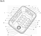
- the fryer tank 2 comprises a drain device 21, better visible on the figures 3 And 5 .
- the fryer tank 2 is made of stamped metal material.
- the fryer tank 2 may in particular be made of stainless steel.
- the fryer tank 2 could in particular be made of enameled steel or aluminum.
- the fryer tank 2 may have level 27 markings.
- the fryer tank 2 has, for example, a thickness of the order of 0.6 mm. Preferably, the tolerance on the thickness of the fryer tank 2 is ⁇ 0.1 mm.
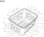
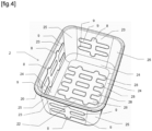
- the fryer tank 2 has a bottom 22 and several sides 23 connected to the bottom 22 by rounded portions 24. The adjacent sides 23 are connected to each other by other rounded portions 25.
- At least one of the sides 23 has a stiffening side stamp 8 forming a lateral recess extending in one direction, as well as another stiffening side stamp 9 forming another lateral recess extending in another direction, and said stiffening side stamp 8 intersects said other stiffening side stamp 9.
- the level markings 27 may extend into one of the stiffening side stamps 8 and/or into one of the other stiffening side stamps 9. However, the level markings 27 are preferably made in flat surfaces. If desired, the level markings 27 extend exclusively into one of the stiffening side stamps 8 and/or into one of the other stiffening side stamps 9.
- all the sides 23 have at least one of the stiffening lateral stampings 8 and at least one of the other stiffening lateral stampings 9.
- all the stiffening side stamps 8 and all the other stiffening side stamps 9 are surrounded by non-stamped portions of the sides 23.
- the direction and the other direction are perpendicular.
- the direction extends perpendicularly relative to the bottom 22 and the other direction extends parallel relative to the bottom 22.
- the fryer tank 2 is parallelepipedal.
- the fryer tank 2 has four sides 23 opposite each other in pairs.
- the sides 23 may have a flat geometry.
- the stiffening side stamps 8 and the other stiffening side stamps 9 extend inside the fryer tank 2.
- the stiffening side stamps 8 and the other stiffening side stamps 9 extend exclusively on the sides 23.
- all the sides 23 have two other lateral stiffening stamps 9 extending parallel to the bottom 22.
- the sides 23 comprise two first opposite sides 23 having two lateral stiffening stamps 8 extending perpendicularly to the bottom 22.
- One of the two other stiffening side stamps 9 of said two opposite sides 23 has a greater height between the stiffening side stamps 8 than outside the stiffening side stamps 8.
- the sides 23 comprise two second opposite sides 23 having a single stiffening side stamp 8 extending perpendicularly to the bottom 22.
- the other stiffening side stamps 9 extend perpendicularly to the stiffening side stamp 8 or to the stiffening side stamps 8.
- the bottom 22 has lower stiffening stamps 28 crossing other lower stiffening stamps 29.
- Each of the lower stiffening stamps 28 forms a lower recess extending in a first direction.
- Each of the other lower stiffening stamps 29 forms another lower recess extending in a second direction.
- the first direction and the second direction are perpendicular.
- the first direction and the second direction each extend parallel or perpendicular to each of the sides.
- the lower stiffening stamps 28 and the other lower stiffening stamps 29 extend toward the inside of the fryer tank 2.
- the bottom 22 has four lower stiffening stamps 28 each crossing two other lower stiffening stamps 29.
- the direction and the other direction are not necessarily perpendicular.
- the direction and the other direction may in particular have an angle of between 60° and 120°, and preferably of between 80° and 100°.
- the other direction does not necessarily extend parallel to the bottom 22.
- the direction does not necessarily extend perpendicular to the bottom 22.
- stiffening side stampings 8 and all of the other stiffening side stampings 9 necessarily extend towards the interior of the fryer tank 2. At least one of the stiffening side stamps 8 and/or at least one of the other stiffening side stamps 9 may in particular extend towards the outside of the fryer tank 2.
- stiffening side stampings 8 and all of the other stiffening side stampings 9 necessarily extend exclusively on the sides 23. At least one of the stiffening side stampings 8 and/or at least one of the other stiffening side stampings 9 may in particular reach at least one of the roundings 24 and/or one of the other roundings 25.
- not all sides 23 necessarily have at least one of the stiffening side stampings 8 and at least one of the other stiffening side stampings 9.
- the bottom 22 does not necessarily have at least one lower stiffening stamp 28 forming a lower recess extending in a first direction and at least one other lower stiffening stamp 29 forming another lower recess extending in a second direction, with said at least one lower stiffening stamp 28 crossing said at least one other lower stiffening stamp 29.
Landscapes
- Engineering & Computer Science (AREA)
- Food Science & Technology (AREA)
- Frying-Pans Or Fryers (AREA)
Claims (21)
- Fritteusenwanne (2), die aus einem tiefgezogenen Metallmaterial ausgeführt ist, die einen Boden (22) und mehrere Seiten (23) aufweist, die mit dem Boden (22) durch Rundungen (24) verbunden sind, wobei mindestens eine der Seiten (23) mindestens eine seitliche Versteifungseinbuchtung (8) aufweist, die eine seitliche Vertiefung bildet, die sich in einer Richtung erstreckt, dadurch gekennzeichnet, dass die mindestens eine der Seiten (23) mindestens eine weitere seitliche Versteifungseinbuchtung (9) aufweist, die eine weitere seitliche Vertiefung bildet, die sich in eine andere Richtung erstreckt, und dass die mindestens eine seitliche Versteifungseinbuchtung (8) die mindestens eine weitere seitliche Versteifungseinbuchtung (9) kreuzt.
- Fritteusenwanne (2) nach Anspruch 1, dadurch gekennzeichnet, dass sich die mindestens eine seitliche Versteifungseinbuchtung (8) und die mindestens eine andere seitliche Versteifungseinbuchtung (9) in Richtung des Inneren der Fritteusenwanne (2) erstrecken.
- Fritteusenwanne (2) nach einem der Ansprüche 1 oder 2, dadurch gekennzeichnet, dass sich die mindestens eine seitliche Versteifungseinbuchtung (8) und die mindestens eine andere seitliche Versteifungseinbuchtung (9) ausschließlich an den Seiten (23) erstrecken.
- Fritteusenwanne (2) nach einem der Ansprüche 1 bis 3, dadurch gekennzeichnet, dass die mindestens eine seitliche Versteifungseinbuchtung (8) und die mindestens eine andere seitliche Versteifungseinbuchtung (9) von nicht tiefgezogenen Teilen der Seiten (23) umgeben sind.
- Fritteusenwanne (2) nach einem der Ansprüche 1 bis 4, dadurch gekennzeichnet, dass die eine Richtung und die andere Richtung einen Winkel zwischen 60° und 120° und vorzugsweise zwischen 80° und 100° umfassen.
- Fritteusenwanne (2) nach einem der Ansprüche 1 bis 5, dadurch gekennzeichnet, dass die eine Richtung und die andere Richtung senkrecht zueinander verlaufen.
- Fritteusenwanne (2) nach einem der Ansprüche 1 bis 6, dadurch gekennzeichnet, dass sich die andere Richtung parallel zum Boden (22) erstreckt.
- Fritteusenwanne (2) nach einem der Ansprüche 1 bis 7, dadurch gekennzeichnet, dass sich die Richtung senkrecht zum Boden (22) erstreckt.
- Fritteusenwanne (2) nach einem der Ansprüche 1 bis 8, dadurch gekennzeichnet, dass mehrere Seiten (23) die mindestens eine seitliche Versteifungseinbuchtung (8) und die mindestens eine andere seitliche Versteifungseinbuchtung (9) aufweisen.
- Fritteusenwanne (2) nach einem der Ansprüche 1 bis 9, dadurch gekennzeichnet, dass alle Seiten (23) die mindestens eine seitliche Versteifungseinbuchtung (8) und die mindestens eine andere seitliche Versteifungseinbuchtung (9) aufweisen.
- Fritteusenwanne (2) nach einem der Ansprüche 1 bis 10, dadurch gekennzeichnet, dass alle Seiten (23) zwei andere seitliche Versteifungseinbuchtungen (9) aufweisen, die sich parallel zum Boden (22) erstrecken.
- Fritteusenwanne (2) nach einem der Ansprüche 1 bis 11, dadurch gekennzeichnet, dass sie quaderförmig ist.
- Fritteusenwanne (2) nach Anspruch 12, dadurch gekennzeichnet, dass zwei gegenüberliegende Seiten (23) zwei seitliche Versteifungseinbuchtungen (8) aufweisen, die sich senkrecht zum Boden (22) erstrecken.
- Fritteusenwanne (2) nach Anspruch 13, dadurch gekennzeichnet, dass eine der zwei anderen seitlichen Versteifungseinbuchtungen (9) der zwei gegenüberliegenden Seiten (23) eine größere Höhe zwischen den seitlichen Versteifungseinbuchtungen (8) als außerhalb der seitlichen Versteifungseinbuchtungen (8) aufweist.
- Fritteusenwanne (2) nach einem der Ansprüche 1 bis 14, dadurch gekennzeichnet, dass der Boden (22) mindestens eine untere Versteifungseinbuchtung (28), die eine untere Vertiefung bildet, die sich in einer ersten Richtung erstreckt, und mindestens eine weitere untere Versteifungseinbuchtung (29) aufweist, die eine andere untere Vertiefung bildet, die sich in einer zweiten Richtung erstreckt, wobei die mindestens eine untere Versteifungseinbuchtung (28) die mindestens eine andere untere Versteifungseinbuchtung (29) kreuzt.
- Fritteusenwanne (2) nach einem der Ansprüche 1 bis 15, dadurch gekennzeichnet, dass sie aus rostfreiem Stahl ausgeführt ist.
- Elektrische Fritteuse (1), umfassend eine Fritteusenwanne (2) und eine elektrische Heizvorrichtung (3), dadurch gekennzeichnet, dass die Fritteusenwanne (2) einem der Ansprüche 1 bis 16 entspricht.
- Elektrische Fritteuse (1) nach Anspruch 17, dadurch gekennzeichnet, dass die elektrische Heizvorrichtung (3) eine elektrische Tauchheizvorrichtung ist, die konfiguriert ist, um in ein Frittierbad eingetaucht zu werden, das in der Fritteusenwanne (2) enthalten ist.
- Elektrische Fritteuse (1) nach Anspruch 17, dadurch gekennzeichnet, dass die elektrische Heizvorrichtung (3) eine elektrische Induktionsheizvorrichtung ist, die zum Erhitzen der Fritteusenwanne (2) durch Induktion vorgesehen ist.
- Elektrische Fritteuse (1) nach einem der Ansprüche 17 bis 19, dadurch gekennzeichnet, dass sie ein Außengehäuse (4) umfasst, das eine obere Öffnung (40) aufweist, und dass die Fritteusenwanne (2) in dem Außengehäuse (4) angeordnet ist.
- Elektrische Fritteuse (1) nach Anspruch 20, dadurch gekennzeichnet, dass die Fritteusenwanne (2) einen äußeren Umfangsrand (20) aufweist, dass das äußere Gehäuse (4) einen oberen Rand (41) umfasst, und dass der äußere Umfangsrand (20) auf dem oberen Rand (41) ruht.
Applications Claiming Priority (2)
| Application Number | Priority Date | Filing Date | Title |
|---|---|---|---|
| FR2010581A FR3115190B1 (fr) | 2020-10-15 | 2020-10-15 | Cuve de friteuse, et friteuse electrique comportant une telle cuve |
| PCT/EP2021/078387 WO2022079140A1 (fr) | 2020-10-15 | 2021-10-14 | Cuve de friteuse, et friteuse electrique comportant une telle cuve |
Publications (3)
| Publication Number | Publication Date |
|---|---|
| EP4228484A1 EP4228484A1 (de) | 2023-08-23 |
| EP4228484C0 EP4228484C0 (de) | 2024-09-18 |
| EP4228484B1 true EP4228484B1 (de) | 2024-09-18 |
Family
ID=74125412
Family Applications (1)
| Application Number | Title | Priority Date | Filing Date |
|---|---|---|---|
| EP21793904.0A Active EP4228484B1 (de) | 2020-10-15 | 2021-10-14 | Fritierbehälter und elektrisches fritiergerät mit einem solchen fritierbehälter |
Country Status (8)
| Country | Link |
|---|---|
| US (1) | US11992157B2 (de) |
| EP (1) | EP4228484B1 (de) |
| CN (1) | CN116348017A (de) |
| AU (1) | AU2021359069A1 (de) |
| CA (1) | CA3192858A1 (de) |
| ES (1) | ES2992758T3 (de) |
| FR (1) | FR3115190B1 (de) |
| WO (1) | WO2022079140A1 (de) |
Family Cites Families (49)
| Publication number | Priority date | Publication date | Assignee | Title |
|---|---|---|---|---|
| US1228956A (en) * | 1917-05-03 | 1917-06-05 | Joseph Henry Noonan | Gas-cooker. |
| US2001285A (en) * | 1934-05-05 | 1935-05-14 | Manning Bowman & Co | Electric cooker |
| US3338156A (en) * | 1965-10-18 | 1967-08-29 | Ancor Corp | Continuous flow apparatus for receiving, transporting, broiling and discharging foodobjects |
| US4913041A (en) * | 1987-11-05 | 1990-04-03 | The Frymaster Corporation | Deep fat frying apparatus |
| US5209218A (en) * | 1992-04-17 | 1993-05-11 | Combustion Concepts, Inc. | Deep frying apparatus |
| KR19980021426U (ko) * | 1996-10-21 | 1998-07-15 | 구자홍 | 튀김물 용기 |
| US5832810A (en) * | 1997-01-10 | 1998-11-10 | Marine Kleen, Inc. | Cooking fluid container and storage system and method |
| US6058245A (en) * | 1998-08-05 | 2000-05-02 | Afc Enterprises, Inc. | Electric boost heater for deep fryer |
| US5947007A (en) * | 1998-12-31 | 1999-09-07 | Alphonso G. Andress | Firebox for vertical hearth barbecue grill |
| FR2788213B1 (fr) * | 1999-01-08 | 2001-03-09 | Moulinex Sa | Friteuse electrique |
| FR2794959B1 (fr) * | 1999-06-18 | 2001-08-17 | Seb Sa | Appareil electrique domestique de cuisson, prevu pour la friture |
| DE50002758D1 (de) * | 1999-09-21 | 2003-08-07 | Nockemann Bernd | Verfahren zum fritieren von fritiergut und vorrichtung zu dessen durchführung |
| US6806444B2 (en) * | 2001-02-21 | 2004-10-19 | William S. Lerner | Heat warning safety device using fiber optic cables |
| GB0107566D0 (en) * | 2001-03-27 | 2001-05-16 | Geddes Allen | Safety cooking ring |
| CA2348686A1 (en) * | 2001-05-23 | 2002-11-23 | Francisco B. Sebastiao | Fat reduced roasting and broiling |
| US7163011B2 (en) * | 2001-10-05 | 2007-01-16 | Eastman Outdoors, Inc. | Outdoor gas grill with auxiliary burner unit, and method of using same |
| US6677556B1 (en) * | 2002-10-28 | 2004-01-13 | Ya Horng Electronic Co., Ltd. | Inner pot of an electric fryer |
| AU2002952394A0 (en) * | 2002-10-31 | 2002-11-14 | Ian Geoffrey Wilson | Deep frying appliance |
| US7340994B2 (en) * | 2003-06-24 | 2008-03-11 | Weber-Stephen Products Co. | Grilling apparatus |
| US6742444B1 (en) * | 2003-08-20 | 2004-06-01 | Eastern Sources Housewares (Hong Kong) Limited | Electric cooking apparatus |
| US7415922B2 (en) * | 2004-03-19 | 2008-08-26 | Meyer Intellectual Properties Limited | Grill pan |
| CN2698214Y (zh) * | 2004-05-31 | 2005-05-11 | 张立 | U形热镀锌锅 |
| US20050098047A1 (en) * | 2004-06-16 | 2005-05-12 | Dan Steinberg | Oven shelf with heat shield that prevents bottom surface burning of baked goods |
| US7141764B1 (en) * | 2004-08-31 | 2006-11-28 | Shumate Eldridge J | Externally heated deep fat fryer |
| US20060219099A1 (en) * | 2005-04-05 | 2006-10-05 | Yun Pan | Automatic cooker |
| US20060272633A1 (en) * | 2005-06-03 | 2006-12-07 | Osias Jovito M Jr | Safe turkey deep fryer |
| US8631739B2 (en) * | 2006-06-22 | 2014-01-21 | Kenyon International, Inc. | Grill |
| US20090025574A1 (en) * | 2007-07-27 | 2009-01-29 | Byrnes Terrence P | Cooking apparatus and methods of use |
| TWM330066U (en) * | 2007-10-12 | 2008-04-11 | Chuo Chown Plastic Co | Improved plate structure for barbecue |
| WO2009055737A2 (en) * | 2007-10-26 | 2009-04-30 | Bivens Thomas H | Filter assembly for fryer and method and use |
| US7881593B2 (en) * | 2007-11-16 | 2011-02-01 | Cfom Inc. | Gas cooking appliance with removable burners and useable work area |
| FR2933287B1 (fr) * | 2008-07-02 | 2013-04-05 | Seb Sa | Appareil de cuisson a resistance electrique plongeante comportant un dispositif d'aspiration des vapeurs de cuisson |
| US20100071564A1 (en) * | 2008-09-15 | 2010-03-25 | Edward Michael Jones | Small batch deep fryer |
| US8616119B2 (en) * | 2010-02-03 | 2013-12-31 | Phillip Penny | Straining skillet |
| CN201734568U (zh) * | 2010-06-04 | 2011-02-09 | 广东新宝电器股份有限公司 | 油炸锅的控温保护结构 |
| US20120031918A1 (en) * | 2010-08-05 | 2012-02-09 | Teddy Gotsis | Interchangeable pan |
| CN201958667U (zh) * | 2011-01-30 | 2011-09-07 | 漳州灿坤实业有限公司 | 一种烤面包机 |
| US20120247448A1 (en) * | 2011-03-31 | 2012-10-04 | TK Products, L.L.C. | Modular Outdoor Cooking System |
| US20130052310A1 (en) * | 2011-08-31 | 2013-02-28 | Calphalon Corporation | Cooking Appliance and Automatic Shut-Off Method for Same |
| AU2012350164B2 (en) * | 2011-12-08 | 2016-08-25 | Breville Pty Limited | Method and apparatus for deep fryer |
| US10376101B2 (en) * | 2012-01-18 | 2019-08-13 | Sal Coco | Cooking oil storage and filtration system |
| US20130298781A1 (en) * | 2012-04-06 | 2013-11-14 | Eden Variety Products, Llc | Portable Passive Convection Cooking Oven |
| US20140020568A1 (en) * | 2012-07-22 | 2014-01-23 | Lee Lisheng Huang | Heat Exchanger For Fryer |
| US9520638B2 (en) * | 2013-01-15 | 2016-12-13 | Fitbit, Inc. | Hybrid radio frequency / inductive loop antenna |
| US20150068944A1 (en) * | 2013-09-06 | 2015-03-12 | Tsann Kuen Zhangzhou | Container |
| US10138019B2 (en) * | 2014-07-12 | 2018-11-27 | Rehrig Pacific Company | Bakery tray assembly |
| CN105174959A (zh) * | 2015-08-05 | 2015-12-23 | 新疆中泰化学股份有限公司 | 电石锅锅底及其制作方法 |
| CN207768210U (zh) * | 2017-07-21 | 2018-08-28 | 广东巧康电器股份有限公司 | 一种底壳与侧板一体空气炸锅 |
| US10743713B2 (en) * | 2017-10-17 | 2020-08-18 | Whirlpool Corporation | Cooking device with inset dispersing pattern |
-
2020
- 2020-10-15 FR FR2010581A patent/FR3115190B1/fr active Active
-
2021
- 2021-10-14 US US18/031,554 patent/US11992157B2/en active Active
- 2021-10-14 CA CA3192858A patent/CA3192858A1/fr active Pending
- 2021-10-14 EP EP21793904.0A patent/EP4228484B1/de active Active
- 2021-10-14 CN CN202180070133.4A patent/CN116348017A/zh active Pending
- 2021-10-14 ES ES21793904T patent/ES2992758T3/es active Active
- 2021-10-14 WO PCT/EP2021/078387 patent/WO2022079140A1/fr not_active Ceased
- 2021-10-14 AU AU2021359069A patent/AU2021359069A1/en active Pending
Also Published As
| Publication number | Publication date |
|---|---|
| US20230346164A1 (en) | 2023-11-02 |
| EP4228484A1 (de) | 2023-08-23 |
| CN116348017A (zh) | 2023-06-27 |
| FR3115190B1 (fr) | 2022-09-30 |
| WO2022079140A1 (fr) | 2022-04-21 |
| US11992157B2 (en) | 2024-05-28 |
| FR3115190A1 (fr) | 2022-04-22 |
| EP4228484C0 (de) | 2024-09-18 |
| AU2021359069A1 (en) | 2023-06-08 |
| ES2992758T3 (en) | 2024-12-17 |
| CA3192858A1 (fr) | 2022-04-21 |
Similar Documents
| Publication | Publication Date | Title |
|---|---|---|
| US20080087673A1 (en) | Cookware with Multiple Component Lid | |
| EP0777433A1 (de) | Gerät zum erwärmen von nahrungsmitteln, insbesondere zum fritieren, mit einem abschirmbehälter | |
| EP4228484B1 (de) | Fritierbehälter und elektrisches fritiergerät mit einem solchen fritierbehälter | |
| EP3282905B1 (de) | Kochzubehör und elektrisches kochgerät mit einem kochzubehör | |
| EP1792555B1 (de) | Kochgerät | |
| WO2008145927A1 (fr) | Article culinaire a portee amelioree et procede de fabrication | |
| EP1032296B1 (de) | Druckkochgerät mit mitteln zum unterstützen eines kochbehälters in einer erhöhten position | |
| EP1557120B1 (de) | Haube von einem elektronischen Waffeleisen | |
| EP3697275B1 (de) | Elektrisches kochgerät mit einem abtropfträger mit einer lagerkonfiguration | |
| EP1064872B1 (de) | Haltevorrichtung eines Deckels auf einem Hausgerät | |
| FR3139709A1 (fr) | Friteuse electrique a resistance immergee comportant un fond de cuve refroidi | |
| EP2401948B1 (de) | Elektrisches Kochgerät mit Kessel und Reflektor | |
| EP2422668B1 (de) | Kochgerät mit Induktionsboden und Flüssigkeitsableitung | |
| EP3886660B1 (de) | Kochanordnung mit einem elektrischen kochgerät und einem ablaufbehälter | |
| EP3801154B1 (de) | Kochgefäss mit einem bimetallelement mit hörbarem alarm | |
| FR3139710A1 (fr) | Friteuse electrique a resistance immergee avec collecteur d’eau | |
| FR2846215A1 (fr) | Accessoire de cuisson pour appareil ou ustensile de cuisson a la vapeur prevu pour realiser des preparations simultanees | |
| FR2749495A1 (fr) | Appareil de cuisson de table a utilisations multiples | |
| BE673479A (de) | ||
| BE506491A (de) | ||
| EP2000066A1 (de) | Medium zum Kochen einer kleinen Menge an Lebensmitteln | |
| JPH02223737A (ja) | 電気こんろ | |
| JPH1033371A (ja) | 鍋及びその製造方法 | |
| BE477557A (de) | ||
| BE898655A (fr) | Gril amovible pour fourneau a gaz |
Legal Events
| Date | Code | Title | Description |
|---|---|---|---|
| STAA | Information on the status of an ep patent application or granted ep patent |
Free format text: STATUS: UNKNOWN |
|
| STAA | Information on the status of an ep patent application or granted ep patent |
Free format text: STATUS: THE INTERNATIONAL PUBLICATION HAS BEEN MADE |
|
| PUAI | Public reference made under article 153(3) epc to a published international application that has entered the european phase |
Free format text: ORIGINAL CODE: 0009012 |
|
| STAA | Information on the status of an ep patent application or granted ep patent |
Free format text: STATUS: REQUEST FOR EXAMINATION WAS MADE |
|
| 17P | Request for examination filed |
Effective date: 20230503 |
|
| AK | Designated contracting states |
Kind code of ref document: A1 Designated state(s): AL AT BE BG CH CY CZ DE DK EE ES FI FR GB GR HR HU IE IS IT LI LT LU LV MC MK MT NL NO PL PT RO RS SE SI SK SM TR |
|
| DAV | Request for validation of the european patent (deleted) | ||
| DAX | Request for extension of the european patent (deleted) | ||
| GRAP | Despatch of communication of intention to grant a patent |
Free format text: ORIGINAL CODE: EPIDOSNIGR1 |
|
| STAA | Information on the status of an ep patent application or granted ep patent |
Free format text: STATUS: GRANT OF PATENT IS INTENDED |
|
| INTG | Intention to grant announced |
Effective date: 20240502 |
|
| GRAS | Grant fee paid |
Free format text: ORIGINAL CODE: EPIDOSNIGR3 |
|
| GRAA | (expected) grant |
Free format text: ORIGINAL CODE: 0009210 |
|
| STAA | Information on the status of an ep patent application or granted ep patent |
Free format text: STATUS: THE PATENT HAS BEEN GRANTED |
|
| AK | Designated contracting states |
Kind code of ref document: B1 Designated state(s): AL AT BE BG CH CY CZ DE DK EE ES FI FR GB GR HR HU IE IS IT LI LT LU LV MC MK MT NL NO PL PT RO RS SE SI SK SM TR |
|
| REG | Reference to a national code |
Ref country code: GB Ref legal event code: FG4D Free format text: NOT ENGLISH |
|
| REG | Reference to a national code |
Ref country code: CH Ref legal event code: EP |
|
| REG | Reference to a national code |
Ref country code: DE Ref legal event code: R096 Ref document number: 602021019042 Country of ref document: DE |
|
| REG | Reference to a national code |
Ref country code: IE Ref legal event code: FG4D Free format text: LANGUAGE OF EP DOCUMENT: FRENCH |
|
| U01 | Request for unitary effect filed |
Effective date: 20241010 |
|
| U07 | Unitary effect registered |
Designated state(s): AT BE BG DE DK EE FI FR IT LT LU LV MT NL PT RO SE SI Effective date: 20241030 |
|
| U20 | Renewal fee for the european patent with unitary effect paid |
Year of fee payment: 4 Effective date: 20241025 |
|
| REG | Reference to a national code |
Ref country code: ES Ref legal event code: FG2A Ref document number: 2992758 Country of ref document: ES Kind code of ref document: T3 Effective date: 20241217 |
|
| PG25 | Lapsed in a contracting state [announced via postgrant information from national office to epo] |
Ref country code: NO Free format text: LAPSE BECAUSE OF FAILURE TO SUBMIT A TRANSLATION OF THE DESCRIPTION OR TO PAY THE FEE WITHIN THE PRESCRIBED TIME-LIMIT Effective date: 20241218 |
|
| PG25 | Lapsed in a contracting state [announced via postgrant information from national office to epo] |
Ref country code: GR Free format text: LAPSE BECAUSE OF FAILURE TO SUBMIT A TRANSLATION OF THE DESCRIPTION OR TO PAY THE FEE WITHIN THE PRESCRIBED TIME-LIMIT Effective date: 20241219 |
|
| PG25 | Lapsed in a contracting state [announced via postgrant information from national office to epo] |
Ref country code: HR Free format text: LAPSE BECAUSE OF FAILURE TO SUBMIT A TRANSLATION OF THE DESCRIPTION OR TO PAY THE FEE WITHIN THE PRESCRIBED TIME-LIMIT Effective date: 20240918 |
|
| PG25 | Lapsed in a contracting state [announced via postgrant information from national office to epo] |
Ref country code: RS Free format text: LAPSE BECAUSE OF FAILURE TO SUBMIT A TRANSLATION OF THE DESCRIPTION OR TO PAY THE FEE WITHIN THE PRESCRIBED TIME-LIMIT Effective date: 20241218 |
|
| PG25 | Lapsed in a contracting state [announced via postgrant information from national office to epo] |
Ref country code: RS Free format text: LAPSE BECAUSE OF FAILURE TO SUBMIT A TRANSLATION OF THE DESCRIPTION OR TO PAY THE FEE WITHIN THE PRESCRIBED TIME-LIMIT Effective date: 20241218 Ref country code: NO Free format text: LAPSE BECAUSE OF FAILURE TO SUBMIT A TRANSLATION OF THE DESCRIPTION OR TO PAY THE FEE WITHIN THE PRESCRIBED TIME-LIMIT Effective date: 20241218 Ref country code: HR Free format text: LAPSE BECAUSE OF FAILURE TO SUBMIT A TRANSLATION OF THE DESCRIPTION OR TO PAY THE FEE WITHIN THE PRESCRIBED TIME-LIMIT Effective date: 20240918 Ref country code: GR Free format text: LAPSE BECAUSE OF FAILURE TO SUBMIT A TRANSLATION OF THE DESCRIPTION OR TO PAY THE FEE WITHIN THE PRESCRIBED TIME-LIMIT Effective date: 20241219 |
|
| PG25 | Lapsed in a contracting state [announced via postgrant information from national office to epo] |
Ref country code: IS Free format text: LAPSE BECAUSE OF FAILURE TO SUBMIT A TRANSLATION OF THE DESCRIPTION OR TO PAY THE FEE WITHIN THE PRESCRIBED TIME-LIMIT Effective date: 20250118 |
|
| PG25 | Lapsed in a contracting state [announced via postgrant information from national office to epo] |
Ref country code: SM Free format text: LAPSE BECAUSE OF FAILURE TO SUBMIT A TRANSLATION OF THE DESCRIPTION OR TO PAY THE FEE WITHIN THE PRESCRIBED TIME-LIMIT Effective date: 20240918 |
|
| PG25 | Lapsed in a contracting state [announced via postgrant information from national office to epo] |
Ref country code: CZ Free format text: LAPSE BECAUSE OF FAILURE TO SUBMIT A TRANSLATION OF THE DESCRIPTION OR TO PAY THE FEE WITHIN THE PRESCRIBED TIME-LIMIT Effective date: 20240918 Ref country code: PL Free format text: LAPSE BECAUSE OF FAILURE TO SUBMIT A TRANSLATION OF THE DESCRIPTION OR TO PAY THE FEE WITHIN THE PRESCRIBED TIME-LIMIT Effective date: 20240918 |
|
| PG25 | Lapsed in a contracting state [announced via postgrant information from national office to epo] |
Ref country code: SK Free format text: LAPSE BECAUSE OF FAILURE TO SUBMIT A TRANSLATION OF THE DESCRIPTION OR TO PAY THE FEE WITHIN THE PRESCRIBED TIME-LIMIT Effective date: 20240918 |
|
| REG | Reference to a national code |
Ref country code: CH Ref legal event code: PL |
|
| PG25 | Lapsed in a contracting state [announced via postgrant information from national office to epo] |
Ref country code: MC Free format text: LAPSE BECAUSE OF FAILURE TO SUBMIT A TRANSLATION OF THE DESCRIPTION OR TO PAY THE FEE WITHIN THE PRESCRIBED TIME-LIMIT Effective date: 20240918 |
|
| PG25 | Lapsed in a contracting state [announced via postgrant information from national office to epo] |
Ref country code: CH Free format text: LAPSE BECAUSE OF NON-PAYMENT OF DUE FEES Effective date: 20241031 |
|
| PLBE | No opposition filed within time limit |
Free format text: ORIGINAL CODE: 0009261 |
|
| STAA | Information on the status of an ep patent application or granted ep patent |
Free format text: STATUS: NO OPPOSITION FILED WITHIN TIME LIMIT |
|
| 26N | No opposition filed |
Effective date: 20250619 |
|
| PG25 | Lapsed in a contracting state [announced via postgrant information from national office to epo] |
Ref country code: IE Free format text: LAPSE BECAUSE OF NON-PAYMENT OF DUE FEES Effective date: 20241014 |
|
| U20 | Renewal fee for the european patent with unitary effect paid |
Year of fee payment: 5 Effective date: 20250926 |
|
| PGFP | Annual fee paid to national office [announced via postgrant information from national office to epo] |
Ref country code: GB Payment date: 20251023 Year of fee payment: 5 |
|
| PG25 | Lapsed in a contracting state [announced via postgrant information from national office to epo] |
Ref country code: CY Free format text: LAPSE BECAUSE OF FAILURE TO SUBMIT A TRANSLATION OF THE DESCRIPTION OR TO PAY THE FEE WITHIN THE PRESCRIBED TIME-LIMIT; INVALID AB INITIO Effective date: 20211014 |
|
| PGFP | Annual fee paid to national office [announced via postgrant information from national office to epo] |
Ref country code: ES Payment date: 20251110 Year of fee payment: 5 |
|
| PG25 | Lapsed in a contracting state [announced via postgrant information from national office to epo] |
Ref country code: HU Free format text: LAPSE BECAUSE OF FAILURE TO SUBMIT A TRANSLATION OF THE DESCRIPTION OR TO PAY THE FEE WITHIN THE PRESCRIBED TIME-LIMIT; INVALID AB INITIO Effective date: 20211014 |