EP4228474B1 - Mechanism for electrically adjusting work surface position - Google Patents
Mechanism for electrically adjusting work surface position Download PDFInfo
- Publication number
- EP4228474B1 EP4228474B1 EP21806301.4A EP21806301A EP4228474B1 EP 4228474 B1 EP4228474 B1 EP 4228474B1 EP 21806301 A EP21806301 A EP 21806301A EP 4228474 B1 EP4228474 B1 EP 4228474B1
- Authority
- EP
- European Patent Office
- Prior art keywords
- vertical
- cable
- guiding element
- adjustment mechanism
- vertical guiding
- Prior art date
- Legal status (The legal status is an assumption and is not a legal conclusion. Google has not performed a legal analysis and makes no representation as to the accuracy of the status listed.)
- Active
Links
Images






Classifications
-
- A—HUMAN NECESSITIES
- A47—FURNITURE; DOMESTIC ARTICLES OR APPLIANCES; COFFEE MILLS; SPICE MILLS; SUCTION CLEANERS IN GENERAL
- A47B—TABLES; DESKS; OFFICE FURNITURE; CABINETS; DRAWERS; GENERAL DETAILS OF FURNITURE
- A47B21/00—Tables or desks for office equipment, e.g. typewriters, keyboards
- A47B21/06—Tables or desks for office equipment, e.g. typewriters, keyboards characterised by means for holding, fastening or concealing cables
-
- A—HUMAN NECESSITIES
- A47—FURNITURE; DOMESTIC ARTICLES OR APPLIANCES; COFFEE MILLS; SPICE MILLS; SUCTION CLEANERS IN GENERAL
- A47B—TABLES; DESKS; OFFICE FURNITURE; CABINETS; DRAWERS; GENERAL DETAILS OF FURNITURE
- A47B5/00—Suspended or hinged panels forming a table; Wall tables
-
- A—HUMAN NECESSITIES
- A47—FURNITURE; DOMESTIC ARTICLES OR APPLIANCES; COFFEE MILLS; SPICE MILLS; SUCTION CLEANERS IN GENERAL
- A47B—TABLES; DESKS; OFFICE FURNITURE; CABINETS; DRAWERS; GENERAL DETAILS OF FURNITURE
- A47B9/00—Tables with tops of variable height
- A47B9/04—Tables with tops of variable height with vertical spindle
-
- E—FIXED CONSTRUCTIONS
- E04—BUILDING
- E04B—GENERAL BUILDING CONSTRUCTIONS; WALLS, e.g. PARTITIONS; ROOFS; FLOORS; CEILINGS; INSULATION OR OTHER PROTECTION OF BUILDINGS
- E04B1/00—Constructions in general; Structures which are not restricted either to walls, e.g. partitions, or floors or ceilings or roofs
- E04B1/62—Insulation or other protection; Elements or use of specified material therefor
- E04B1/74—Heat, sound or noise insulation, absorption, or reflection; Other building methods affording favourable thermal or acoustical conditions, e.g. accumulating of heat within walls
- E04B1/82—Heat, sound or noise insulation, absorption, or reflection; Other building methods affording favourable thermal or acoustical conditions, e.g. accumulating of heat within walls specifically with respect to sound only
- E04B1/8218—Heat, sound or noise insulation, absorption, or reflection; Other building methods affording favourable thermal or acoustical conditions, e.g. accumulating of heat within walls specifically with respect to sound only soundproof enclosures
-
- E—FIXED CONSTRUCTIONS
- E04—BUILDING
- E04H—BUILDINGS OR LIKE STRUCTURES FOR PARTICULAR PURPOSES; SWIMMING OR SPLASH BATHS OR POOLS; MASTS; FENCING; TENTS OR CANOPIES, IN GENERAL
- E04H1/00—Buildings or groups of buildings for dwelling or office purposes; General layout, e.g. modular co-ordination or staggered storeys
- E04H1/12—Small buildings or other erections for limited occupation, erected in the open air or arranged in buildings, e.g. kiosks, waiting shelters for bus stops or for filling stations, roofs for railway platforms, watchmen's huts or dressing cubicles
- E04H1/125—Small buildings, arranged in other buildings
-
- E—FIXED CONSTRUCTIONS
- E06—DOORS, WINDOWS, SHUTTERS, OR ROLLER BLINDS IN GENERAL; LADDERS
- E06B—FIXED OR MOVABLE CLOSURES FOR OPENINGS IN BUILDINGS, VEHICLES, FENCES OR LIKE ENCLOSURES IN GENERAL, e.g. DOORS, WINDOWS, BLINDS, GATES
- E06B3/00—Window sashes, door leaves, or like elements for closing wall or like openings; Layout of fixed or moving closures, e.g. windows in wall or like openings; Features of rigidly-mounted outer frames relating to the mounting of wing frames
- E06B3/04—Wing frames not characterised by the manner of movement
- E06B3/06—Single frames
-
- A—HUMAN NECESSITIES
- A47—FURNITURE; DOMESTIC ARTICLES OR APPLIANCES; COFFEE MILLS; SPICE MILLS; SUCTION CLEANERS IN GENERAL
- A47B—TABLES; DESKS; OFFICE FURNITURE; CABINETS; DRAWERS; GENERAL DETAILS OF FURNITURE
- A47B2200/00—General construction of tables or desks
- A47B2200/0035—Tables or desks with features relating to adjustability or folding
- A47B2200/005—Leg adjustment
- A47B2200/0056—Leg adjustment with a motor, e.g. an electric motor
-
- A—HUMAN NECESSITIES
- A47—FURNITURE; DOMESTIC ARTICLES OR APPLIANCES; COFFEE MILLS; SPICE MILLS; SUCTION CLEANERS IN GENERAL
- A47B—TABLES; DESKS; OFFICE FURNITURE; CABINETS; DRAWERS; GENERAL DETAILS OF FURNITURE
- A47B83/00—Combinations comprising two or more pieces of furniture of different kinds
- A47B83/02—Tables combined with seats
- A47B83/023—Booth-type arrangements
Definitions
- the present disclosure generally relates to mechanisms for adjusting work surface position, such as mechanisms for electrically height adjustable sit stand desks.
- the solution also relates to wall structures and tables comprising such mechanism.
- Height adjustable including electrically height adjustable, desks, such as electrically height adjustable sit stand desks, are known in the industry. Typically, height adjustment is effectuated by a height adjustment mechanism.
- An electrical height adjustment mechanism employs a cable or cables to convey electricity and/or electrical signals, for example, between a control unit and a user interface of the electrical height adjustment mechanism.
- an adjustment mechanism assembly for adjusting a work surface position vertically, comprising
- the vertical support member extends vertically from within the vertical guiding element to outside the vertical guiding element. In certain other embodiments, the vertical support member resides completely within the vertical guiding element.
- the vertical support member is preferably arranged parallelly with the vertical guiding element, more preferably the vertical support member is arranged coaxially with the vertical guiding element.
- the work surface support element is arranged to protrude horizontally from within the vertical guiding element between the (top and bottom) ends of the vertical guiding element. In certain embodiments, the work surface support element is configured to move along the vertical guiding element in the longitudinal direction of the vertical guiding element.
- the work surface support element is engaged with the vertical guiding element through a vertically oriented slit in a side of the vertical guiding element.
- the work surface support element is preferably configured to be movable vertically within said vertically oriented slit with electric actuation.
- the height (in the vertical or longitudinal direction) of the vertical guiding element or/and the vertical support member is/are constant. In certain embodiments, the height (in the vertical or longitudinal direction) of the adjustment mechanism assembly is constant.
- the vertical guiding element is a one-piece element.
- the vertical guiding element consists essentially of one vertical guiding member (in contrast of having for example a telescopic structure).
- Said vertical guiding member is preferably a one-piece member, such as a one-piece column.
- the vertical guiding element is formed of a shell of a column (or of an outer shell of a column assembly).
- the work surface support element is adapted to provide support for a work surface, such as a table top.
- the vertical support member is a pipe preferably comprising a vertically extending slit, and the spiraled portion of the cable is housed within the pipe.
- the vertical guiding element(s) 6 house an actuator such as a motor 31 to effect the movement of the work surface support element(s) 8.
- an actuator may effect the rotational movement of a threaded rod 30 and, consistent with what has been described above, thus effecting the movement of the work surface support element(s) 8.
- the adjustment mechanical assembly 1 may comprise a control unit 7, for example as shown in the embodiment of Figure 1 .
- the vertical guiding element 6 may be a rod-type support member 3,3 a , for example as shown in the embodiment of Figures 1-5 , a pipe-type support member 3,3 b , for example as shown in the embodiment of Figures 9a-9d , an enclosure-type support member 3,3 c , for example as shown in the embodiment of Figures 10a-10d , and/or a wall-or plate-type support member 3,3 d , for example as shown in the embodiment of Figures 11a-11d .
- Such an arrangement also enables a setup in which the entire spiraled portion 2' may reside outside the vertical guiding element 6 in its contracted state (c.f. also Figure 8b ) while allowing it to extend into the inside of the vertical guiding element 6 in its extended state (c.f. also Figure 8a ).
- the mounting support element 5 may be attached to the same vertical end of the vertical guiding element 6 in which said aperture 40 resides.
- the mounting support element 5 may be provided with an aperture that coincides with the aperture 40 of the vertical guiding element 6 (coinciding aperture), for example as shown in the embodiment of Figure 5 .
- reference sign 40 refers to both the aperture of the vertical guiding element 6 and a coinciding aperture of the mounting support element 5.
- the height (in the vertical or longitudinal direction) of the adjustment mechanism assembly 1 is constant.
- the height of the adjustment mechanism assembly 1 is invariable or fixed, i.e. the height of the adjustment mechanism assembly 1 is configured to be unchangeable.
- a gained advantage is that the assembly 1 can be firmly attached to the mounting surface or wall by the vertical guiding element 6, for example, at top and bottom ends of the vertical guiding element 6. Further, a non-contracting vertical guiding element is easier to manufacture.
- the height (in the vertical or longitudinal direction) of the vertical guiding element 6 or/and the vertical support member 3 may be constant (invariable or fixed or configured to be unchangeable).
- the vertical guiding element (or its outer shell) is a one-piece element.
- the vertical guiding element consists essentially of one vertical guiding member.
- Said vertical guiding member is preferably a one-piece member, such as a one-piece column.
- the adjustment mechanism assembly 1 in certain embodiments is non-telescopic.
- the vertical support member 3 may be a rod-type support member 3,3 b , for example as shown in the embodiment of Figure 5 , a pipe-type support member 3,3 b , for example as shown in the embodiment of Figures 9a-9d , an enclosure-type support member 3,3 c , for example as shown in the embodiment of Figures 10a-10c , and/or a wall- or plate-type support member 3,3 d , for example as shown in the embodiments of Figures 11a-11d .
- the vertical support member 3 resides completely within the vertical guiding element 6.
- the vertical support member 3 residing within the vertical guiding element 6 may be any type of vertical support member described in the foregoing.
- the vertical guiding element 6 may be for example a rod-type support member 3,3 a , a pipe-type support member 3,3 b , an enclosure-type support member 3,3 c , and/or a wall-or plate-type support member 3,3 d .
- the vertical guiding element 6 is configured to support the vertical support member 3 to provide positional and alignment stability for the vertical support member 3.
- positional and alignment stability is desirable to prevent the support member 3 from changing position and/or alignment as described in the foregoing.
- an end portion of the vertical support member 3 may be connected to an end portion of the vertical guiding element 6 to provide positional and alignment stability for the vertical support member 3.
- a support element 4 may not be needed.
- the upper end of the vertical support member 3 may terminate at and be supported by the top portion (roof) of the vertical guiding element 6, as shown for example in Figure 12c .
- the vertical support member 3 extends vertically from within the vertical guiding element 6 to outside the vertical guiding element 6 positional and alignment stability for the vertical support member 3 may be provided without necessarily needing a support element 4.
- the upper end of the vertical support member 3 may extend to outside the vertical guiding element 6 and terminate at and be supported by a mounting support element 5, as shown for example in Figure 12b .
- end of the support member 3 which resides within the vertical guiding element 6 extends so far, i.e. to such a vertical position, that it still surpasses the work surface support element 8 when the work surface support element 8 is at a position that, in a certain application, is arranged to be its farthest position from the other or opposite end of the vertical support member 3.
- the vertical support member 3 should advantageously be, within the vertical guiding element 6, so long that the spiraled portion 2' of the cable 2 remains supported by the vertical support member 3 even when fully extended so that when the spiraled portion 2' of the cable 2 thereafter contracts, there is no risk of a portion of the spiraled portion 2' of the cable 2 to contract past the vertical support member 3.
- the work surface support element 8 and/or the support element 4 for the vertical support member 3 is (are each) equipped with a strain reliever 41 which provides a fixing point for the cable 2.
- a strain reliever 41 which provides a fixing point for the cable 2.
- the strain reliever 41 at the work surface support element 8 may be configured such that it envelops the cable 2 at this fixing point, for example as shown in the embodiment of Figure 5 , to protect the cable 2 for example from hitting the sides of the slit through which the work surface support element 8 extends and the cable 2 enters into the vertical guiding element 6.
- the strain reliever 41 at the work surface support element 8 may be configured such that it extends inwards into the vertical guiding element 6 and near or adjacent to the slit 42.
- the cable 2 may comprise more than one or several electricity- and/or signal-conveying wires while adhering to the principles described above.
- the cable 2 can take the form of a bundle of individual cables while adhering to the principles described above.
Landscapes
- Engineering & Computer Science (AREA)
- Architecture (AREA)
- Physics & Mathematics (AREA)
- Civil Engineering (AREA)
- Structural Engineering (AREA)
- Acoustics & Sound (AREA)
- Electromagnetism (AREA)
- Building Environments (AREA)
- Casings For Electric Apparatus (AREA)
- Electric Cable Arrangement Between Relatively Moving Parts (AREA)
- Tables And Desks Characterized By Structural Shape (AREA)
- Installation Of Indoor Wiring (AREA)
Description
- The present disclosure generally relates to mechanisms for adjusting work surface position, such as mechanisms for electrically height adjustable sit stand desks. The solution also relates to wall structures and tables comprising such mechanism.
- Height adjustable, including electrically height adjustable, desks, such as electrically height adjustable sit stand desks, are known in the industry. Typically, height adjustment is effectuated by a height adjustment mechanism.
- An electrical height adjustment mechanism employs a cable or cables to convey electricity and/or electrical signals, for example, between a control unit and a user interface of the electrical height adjustment mechanism.
- Currently, at least some cables of electrical height adjustment mechanisms, particularly the cable or cables running between the control unit and the user interface, are mostly or fully exposed creating a nuisance for the user, for example by interfering with free movement of the user's legs. Moreover, such an exposed cable or cables create a risk of cable damage for example in case of forceful contact between the cable and the user or another external object.
- A known adjustment mechanism assembly is disclosed in
US 9 593 481 B2 - Therefore, there is a need to address these deficiencies.
- The appended claims define the scope of protection.
- According to the invention, there is provided an adjustment mechanism assembly for adjusting a work surface position vertically, comprising
- a non-telescopic vertical guiding element consisting of one vertical guiding member,
- a work surface support element engaged with the vertical guiding element and configured to be movable vertically with electric actuation,
- means for said electric actuation comprising a cable, and
- a non-telescopic vertical support member which resides at least partially within the vertical guiding element,
- which cable comprises a spiraled portion between its termini, which spiraled portion is supported with respect to its central axis by the vertical support member.
- In certain embodiments, the vertical support member extends vertically from within the vertical guiding element to outside the vertical guiding element. In certain other embodiments, the vertical support member resides completely within the vertical guiding element. The vertical support member is preferably arranged parallelly with the vertical guiding element, more preferably the vertical support member is arranged coaxially with the vertical guiding element.
- In certain embodiments, the work surface support element is arranged to protrude horizontally from within the vertical guiding element between the (top and bottom) ends of the vertical guiding element. In certain embodiments, the work surface support element is configured to move along the vertical guiding element in the longitudinal direction of the vertical guiding element.
- In certain embodiments, the work surface support element is engaged with the vertical guiding element through a vertically oriented slit in a side of the vertical guiding element. The work surface support element is preferably configured to be movable vertically within said vertically oriented slit with electric actuation.
- In certain embodiments, the height (in the vertical or longitudinal direction) of the vertical guiding element or/and the vertical support member is/are constant. In certain embodiments, the height (in the vertical or longitudinal direction) of the adjustment mechanism assembly is constant.
- In certain embodiments, the vertical guiding element is a one-piece element. According to the invention, the vertical guiding element consists essentially of one vertical guiding member (in contrast of having for example a telescopic structure). Said vertical guiding member is preferably a one-piece member, such as a one-piece column. In certain embodiments, the vertical guiding element is formed of a shell of a column (or of an outer shell of a column assembly).
- In certain embodiments, the spiraled portion is configured to extend and contract with vertical movement of the work surface support element. Advantageously, said extending and contracting is in the longitudinal direction of the spiraled portion.
- In certain embodiments, the work surface support element is adapted to provide support for a work surface, such as a table top.
- In certain embodiments, the means for electric actuation comprises an electrical user interface and a control unit connected with the cable to the electrical user interface. In certain embodiments, the means for electric actuation comprises an electrical user interface, a control unit connected with the cable to the electrical user interface, and at least one actuator, such as motor, effecting the movement of the work surface support element and connected to the control unit.
- In certain embodiments, the adjustment mechanism assembly comprises an electrical user interface and a control unit or an equivalent connection point connected with the cable to the electrical user interface. In certain embodiments, the cable, en route from the electrical user interface to the control unit or an equivalent connection point, and before the spiraled portion, enters into inside the vertical guiding element at the work surface support element.
- In certain embodiments, at least a portion of the spiraled portion of the cable resides outside the vertical guiding element. In certain other embodiments, the the spiraled portion of the cable resides completely within the vertical guiding element. In certain embodiments, at least a portion of the spiraled portion of the cable resides within the vertical guiding element.
- In certain embodiments, the vertical guiding element comprises an aperture through which the vertical support mechanism or member extends vertically from within the vertical guiding element to the outside the vertical guiding element. In certain embodiments, at least a portion of the spiraled portion of the cable extends through the aperture and resides outside the vertical guiding element.
- In certain embodiments, the cable is arranged to enter into inside of the vertical guiding element at the work surface support element.
- In certain embodiments, that end portion of the vertical support member which resides outside the vertical guiding element is connected to a support element configured to prevent movement of said end portion of the vertical support member. In certain embodiments, that end of the vertical support member which resides outside the vertical guiding element is connected to a support element adapted to hold said end of the vertical support member in place.
- According to the invention, the vertical support member and the vertical guiding element are configured to be unmoving. The vertical guiding member in itself is stationary or immobile or constant in height. The vertical support member in itself is stationary or immobile or constant in height.
- In certain embodiments, the adjustment mechanism assembly comprises at least two strain relievers connected to the cable such that the spiraled portion of the cable resides between two strain relievers.
- In certain embodiments, the support element comprises one of said two strain relievers, the work surface support element comprises another of said two strain relievers, and the spiraled portion of the cable resides between these two strain relievers.
- In certain embodiments, the vertical support member is a rod and the spiraled portion of the cable is spiraled around the rod.
- In certain embodiments, the vertical support member is a pipe preferably comprising a vertically extending slit, and the spiraled portion of the cable is housed within the pipe.
- In certain embodiments, the vertical support member is an enclosure preferably comprising a vertically extending slit, and the spiraled portion of the cable is housed within the enclosure.
- In certain embodiments, the vertical support member is a plate or a wall, and the spiraled portion of the cable resides next to the plate or the wall.
- In certain embodiments, the adjustment mechanism assembly comprises a further or additional vertical guiding element, and a further or additional work surface support element engaged with the further or additional vertical guiding element and configured to be movable vertically. In certain embodiments, the adjustment mechanism assembly comprises more than one vertical guiding element and a respective worksurface support element is engaged to each vertical guiding element.
- In certain embodiments, the adjustment mechanism assembly comprises at least one mounting support element connected to the vertical guiding element(s) and adapted for mounting the adjustment mechanism assembly for example to a mounting surface, such as a wall.
- According to a second example aspect, there is provided a wall structure comprising an adjustment mechanism assembly according to the invention.
- In certain embodiments, the adjustment mechanism assembly is mounted to an outer surface of the wall structure.
- In certain embodiments, the adjustment mechanism assembly is mounted to a mounting surface within the wall structure such that the work surface support element(s) extend to outside of the wall structure through vertical slit(s) in the wall structure configured to allow the work surface support element(s) to move vertically. According to a third example aspect, there is provided a height-adjustable table comprising an adjustment mechanism assembly according the first example aspect, and a work surface supported by the work surface support element(s).
- In certain embodiments, the height adjustable table comprises at least one guiding element support member, such as a leg, adapted to support the vertical guiding element(s) in an upright position.
- The embodiments in the foregoing are used merely to explain selected aspects or steps that may be utilized in different implementations. Some embodiments may be presented only with reference to certain example aspects. It should be appreciated that corresponding embodiments may apply to other example aspects as well.
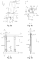
- Some example embodiments will be described with reference to the accompanying figures, in which:
- Figure 1
- schematically illustrates, according to an example embodiment, an adjustment mechanism assembly according to the disclosed solution as viewed from the front.
- Figure 2
- schematically illustrates the adjustment mechanism assembly of
Figure 1 and a work surface with a cable connected electrical user interface connected thereto, as viewed from a side. Work surface movement is illustrated by way of depicting another exemplary position for the work surface with dashed lines. - Figure 3
- schematically illustrates the adjustment mechanism assembly of
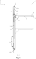
Figure 1 as viewed from the front and in a cross-section denoted inFigure 2 . - Figure 4
- schematically illustrates the adjustment mechanism assembly of
Figure 1 plus a work surface with a cable connected electrical user interface, as viewed from a side and in a cross-section denoted inFigure 1 . Work surface movement is illustrated by way of depicting another exemplary position for the work surface with dashed lines. - Figure 5
- schematically illustrates a partial enlargement of the adjustment mechanism assembly of
Figure 1 as depicted diagonally from above. - Figure 6
- schematically illustrates possible functionalities of an electrical user interface.
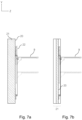
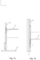
- Figures 7a-d
- schematically illustrate example embodiments of mounting setups for an adjustment mechanism assembly according to the disclosed solution, as viewed from a side and with the adjustment mechanism depicted in the same cross-section as in
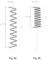
Figure 3 . - Figure 8a
- schematically illustrates the effective length and the central axis of a spiraled portion of a cable in an extended state of the spiraled portion.
- Figure 8b
- schematically illustrates the effective length and the central axis of a spiraled portion of a cable in a contracted state of the spiraled portion and with the absolute length of the portion of the cable forming the spiraled portion being the same as in
Figure 8a . - Figures 9a-9d
- schematically illustrate, according to another example embodiment, an adjustment mechanism assembly according to the disclosed solution.
- Figures 10a-10d
- schematically illustrate, according to yet another example embodiment, an adjustment mechanism assembly according to the disclosed solution.
- Figures 11a-11d
- schematically illustrate, according to still another example embodiment, an adjustment mechanism assembly according to the disclosed solution.
- Figures 12a-12c
- schematically illustrate, according to yet further example embodiments, adjustment mechanism assemblies according to the disclosed solution.
- The figures are intended for illustrating the idea of the disclosed solution. Therefore, the figures are not in scale or suggestive of a definite layout of system components.
- In the following description, like reference signs denote like elements or steps. Reference is made to the figures with the following numerals and denotations:
- 1
- Adjustment mechanism assembly
- 2
- Cable, for electrical user interface connectivity
- 2'
- Spiraled portion, of cable
- 3
- Vertical support member, for spiraled portion, of cable
- 3a
- Rod, -type of vertical support member, for spiraled portion, of cable
- 3b
- Pipe, -type of vertical support member, for spiraled portion, of cable
- 3c
- Enclosure, -type of vertical support member, for spiraled portion, of cable
- 3d
- Wall or plate, -type of vertical support member, for spiraled portion, of cable
- 4
- Support element, for vertical support member
- 5, 5a, 5b
- Mounting support element
- 6, 6a, 6b
- Vertical guiding element
- 7
- Control unit
- 8, 8a, 8b
- Work surface support element
- 9
- Work surface
- 10
- Electrical user interface
- 11
- Electrical socket
- 12
- Data connection socket
- 13
- Network connection socket
- 14
- Height adjustment control
- 15
- Control
- 16
- Wireless charging element
- 20
- Mounting surface
- 21
- Wall structure
- 22
- Concealment cover
- 23
- Leg, for the adjustment mechanism assembly
- 30
- Threaded rod
- 31
- Motor
- 40
- Aperture
- 41
- Strain reliever, for cable
- 42
- Slit, for cable, in vertical support member
- C
- Central axis, of spiraled portion, of cable
- L
- Effective length, for spiraled portion, of cable
- X, Y, Z
- Orthogonal coordinates in the frame of adjustment mechanism assembly
- Electrically adjustable height adjustment mechanisms for work surfaces may comprise one or more guiding elements, for example columns, typically vertically oriented, which guiding elements may house means for adjusting the vertical position or height of elements for supporting a work surface. In implementations comprising more than one guiding element, the guiding elements are preferably distinct or separate guiding elements positioned a horizontal distance or distances away from each other. Electrical adjusting mechanisms may comprise a user-accessible electrical user interface, such as raising and lowering command buttons to change the height of elements supporting the work surface and thus effectively change the height of the work surface. The electrical user interface may be positioned at or in the immediate vicinity of the work surface.
- The electrical user interface typically requires an electrical cable to convey electricity and/or electrical signals to, for example, a control unit of the adjustment mechanism to execute user commands provided with the electrical user interface and/or to convey electricity to the electrical user interface for the user's disposal. Often, the command unit resides elsewhere in the adjustment mechanism, i.e. distant from the electrical user interface. However, a cable may be arranged from the electrical user interface to the command unit or an equivalent connecting point.
- The present disclosure provides an
adjustment mechanism assembly 1 for electrically adjusting a vertical position of awork surface 9 connectable to theadjustment mechanism assembly 1, for example as shown in the embodiment ofFigure 4 . Thus, the disclosed solution comprises anadjustment mechanism assembly 1 for e.g. electrically adjusting the height of a table. - The
adjustment mechanism assembly 1 comprises at least onevertical guiding element 6 advantageously providing attachment and/or movement guidance for a worksurface support element 8 or several worksurface support elements 8 to which awork surface 9 may be attached, for example as shown in the embodiment ofFigure 1 . Thevertical guiding element 6 may be provided with, or comprise, a slit through which at least a part of the worksurface support element 8 may extend into thevertical guiding element 6 for connection or engagement therein. Said slit may be a slit arranged longitudinally in a side of thevertical guiding element 6, between the ends of thevertical guiding element 6. The worksurface support element 8 is preferably configured to be movable vertically within said slit with electric actuation. The worksurface support element 8 may be partially housed within thevertical guiding element 6. The worksurface support element 8 is arranged to protrude horizontally from within thevertical guiding element 6 to the outside of thevertical guiding element 6. The worksurface support element 8 may be arranged to protrude from a side of thevertical guiding element 6, for example through the longitudinally arranged slit described above, between the ends of thevertical guiding element 6. - The
vertical guiding element 6 may, for example within it, comprise a mechanism for providing movement for the worksurface support element 8. For example as shown in the embodiment ofFigure 3 , thevertical guiding element 6 may, for example within it, comprise a threadedrod 30 which extends through the worksurface support element 8, for example through the portion of the worksurface support element 8 that is housed within thevertical guiding element 6. In such embodiments, the portion of the worksurface support element 8 through which the treatedrod 30 extends may comprise threads configured to interconnect with the threadedrod 30 so that when the threadedrod 30 rotates, the worksurface support element 8 moves accordingly. - According to the invention, the
adjustment mechanism assembly 1 comprises onevertical guiding element 6. Such a setup is advantageous in e.g. applications in which small size for theadjustment mechanism assembly 1 is desired. - In certain other embodiments, for example as shown in the embodiment of
Figures 1 and3 , theadjustment mechanism assembly 1 comprises twovertical guiding elements 6a, 6b. Thevertical guiding elements 6a, 6b may be two distinct guiding elements positioned a (horizontal) distance away from each other. Such a setup is advantageous in e.g. applications in which it is advantageous to have thework surface 9 supported at or near both its ends to prevent thework surface 9 from wobbling or tilting. - In certain yet other embodiments, the
adjustment mechanism assembly 1 comprises three or morevertical guiding elements 6. Thevertical guiding elements 6 may be distinct guiding elements positioned a (horizontal) distance away from each other. Such a setup is advantageous in e.g. applications in which it is advantageous to provide great amount of lifting or supporting force for aheavy work surface 9 or awork surface 9 with heavy objects on it. - For example as shown in the embodiment of
Figure 7c , theadjustment mechanism assembly 1 may be configured to stand on a floor e.g. in applications in which a floor-standing or independently standing table setup is desired. In such embodiments, theadjustment mechanism assembly 1 may be coupled with or comprise a guiding element support member, such as a horizontally oriented support plate or aleg 23 or several such plates orlegs 23, to support theadjustment mechanism assembly 1 in an upright position. Particularly, said guiding element support member or members may be adapted to support avertical guiding element 6 orvertical guiding elements 6 of theadjustment mechanism assembly 1 in an upright position. - In certain embodiments, the
adjustment mechanism assembly 1 may be enveloped at least partially with aconcealment cover 22 to prevent inappropriate or accidental user interaction with parts, especially moving parts, of theadjustment mechanism assembly 1. Particularly, aconcealment cover 22 may be employed in a floor-standing or independently standing setup, or in a setup where theadjustment mechanism assembly 1 is mounted on the outer surface of a wall (wall surface-mounted setup), for example as shown in the embodiments ofFigure 7 c andFigure 7 a, respectively. - In certain embodiments, the
adjustment mechanism assembly 1 is mounted to a mountingsurface 20. The mounting surface may be for example a wall, for example a surface of a wall, as shown for example in the embodiment ofFigure 7 a. - In certain embodiments, the
adjustment mechanism assembly 1 may be embedded within a wall orwall structure 21 such that a portion of the work surface support element(s) 8 extend(s) from within thewall structure 21 for connection with awork surface 9, for example as shown in the embodiment ofFigure 7 b. Such an arrangement is advantageous as the vertical guiding element(s) 6 in particular do not consume any space from the working area in which thework surface 9 is installed. Such an arrangement is also advantageous as the vertical guiding element(s) 6 in particular do not interfere with humans, objects or acoustics within the working area in which thework surface 9 is installed. Such an arrangement is also advantageous as the vertical guiding element(s) 6 in particular do not interfere cleaning the surface of thewall structure 21 within which theadjustment mechanism assembly 1 is embedded. - The wall to which the adjustment mechanism assembly may be mounted, for example by attaching it to a wall surface or by embedding it within the
wall structure 21, may be, for example, a wall of a building or a wall of an enclosed sound-attenuating portable structure such as an office booth or an office pod. - For mounting the
adjustment mechanism assembly 1 comprising the vertical guiding element(s) 6, the vertical guiding element(s) 6 may be equipped with e.g. fixture apertures or integral mounting fixings. Alternatively, or in addition, theadjustment mechanism assembly 1 may comprise one or more mounting support elements 5 via which theadjustment mechanism assembly 1 can be attached to awall structure 21, either onto a surface or within it. Examples of mounting support elements 5 are shown for example in the embodiment ofFigure 1 . The mounting support element(s) 5 may be connected to the vertical guiding element(s) 6 such that the mounting support element(s) 5 may provide positional rigidity to the vertical guiding element(s) 6. Such mounting support element(s) 5 may be horizontally aligned. - In certain embodiments, for example as illustrated in the embodiment of
Figure 1 , theadjustment mechanism assembly 1 comprises two horizontal or essentially horizontal mounting support elements 5a, 5b each of which is connected to avertical guiding element 6. For example, as shown in the embodiment ofFigure 1 comprising twovertical guiding elements 6a, 6b, theadjustment mechanism assembly 1 may comprise two horizontal or essentially horizontal mounting support elements 5a, 5b each of which is connected to each of twovertical guiding elements 6a, 6b. Particularly, as shown in the embodiment ofFigure 1 comprising twovertical guiding elements 6a, 6b, theadjustment mechanism assembly 1 may comprise one upper horizontal mounting support element 5a which is connected to the upper end of each of the twovertical guiding elements 6a, 6b, and one lower horizontal mounting support element 5b which is connected to the lower end of each of the twovertical guiding elements 6a, 6b. Such an arrangement is advantageous in that it offers high dimensional and structural rigidity as the horizontal support elements 5a, 5b and thevertical guiding elements 6a, 6b form a horizontally and vertically extending structure with spatially spaced out connecting points, and as the mounting points of theadjustment mechanism 1 can be spatially spaced out on the plane of thewall structure 21. - In certain embodiments, for example as shown in the embodiment of
Figure 3 , the vertical guiding element(s) 6 house an actuator such as amotor 31 to effect the movement of the work surface support element(s) 8. For example, such an actuator may effect the rotational movement of a threadedrod 30 and, consistent with what has been described above, thus effecting the movement of the work surface support element(s) 8. To provide actuation signals and/or power to the actuator(s) such as motor(s) 31, the adjustmentmechanical assembly 1 may comprise acontrol unit 7, for example as shown in the embodiment ofFigure 1 . - To provide user convenience and especially in embodiments in which the
control unit 7 is, for example together with the vertical guiding element(s) 6, embedded within awall structure 21, a user of theadjustment mechanism assembly 1 is provided anelectrical user interface 10, preferably within his or her immediate reach. Such anelectrical user interface 10 may be provided, for example, within, on or under thework surface 9 such as a table top. The embodiment ofFigure 2 , for example, shows an example installation of anelectrical user interface 10 under thework surface 9. It is to be understood that inFigures 1 and3 the electrical user interface is not illustrated with any respect to its physical positioning. -
Figure 6 shows an example of anelectrical user interface 10. Theelectrical user interface 10 may comprise aheight adjustment control 14, for example in the form of an "upwards" button and a "downwards" button or an equivalent control interface to provide corresponding movement command signals to effect the movement of the work surface support element(s) 8 and thus the movement of thework surface 9. Such movement command signals typically travel through from theelectrical user interface 10 to thecontrol unit 7 which, in turn, provides actuation signals and/or power to the actuators effecting the movement of the work surface support element(s) 8, as schematically illustrated in the embodiment ofFigure 1 for example. - As illustrated for example in
Figure 6 , theelectrical user interface 10 may comprise in addition to theheight adjustment control 14, for example, - an
electrical socket 11 to provide electricity to (the user's) appliances such as a laptop computer charger; and/or - a
data connection socket 12 such as an USB interface socket to provide data connectivity to thecontrol unit 7 and/or to devices external to theadjustment mechanism assembly 1; and/or - a
network connection socket 13 such as an Ethernet network port to provide (the user with) a network connectivity; and/or - a
wireless charging element 16 to provide the user with wireless charging of e.g. a mobile phone on thework surface 9 without a need of a charging cable; and/or - another
control 15 to control other functionalities of theadjustment mechanism assembly 1 such as the speed with which thework surface 9 moves when moved and/or to control functionalities external to theadjustment mechanism assembly 1 such as the lighting and/or the ventilation of a working area, such as a sound-insulation booth, in which thework surface 9 resides. - The
electrical user interface 10 may be connected to thecontrol unit 7 with anelectrical cable 2, as schematically illustrated inFigure 1 for example. - It is advantageous to convey or arrange the
cable 2 at least partially within the elements of theadjustment mechanism assembly 1. This may for example prevent damage to thecable 2 due to user interference of contact with other human beings or foreign objects and to provide user with convenience without disturbing and interfering cable(s) 2. - In certain embodiments, a portion of (the length of) the
cable 2 is conveyed or arranged within thevertical guiding element 6. A portion (of the length) of thecable 2 may optionally be conveyed within other elements of theadjustment mechanism assembly 1 as well, such as within or concealed by a mounting support element 5. - In certain embodiments, the
cable 2 enters into the inside of thevertical guiding element 6 at the worksurface support element 8, for example as shown in the embodiment ofFigure 4 . Particularly, the route of thecable 2 from theelectrical user interface 10 to thecontrol unit 7 or an equivalent connection point may be arranged such that on its way from theelectrical user interface 10 towards thecontrol unit 7, thecable 2 enters into the inside of thevertical guiding element 6 at the worksurface support element 8. - The
vertical guiding element 6 of theadjustment mechanism assembly 1 within which a portion of thecable 2 is conveyed, comprises a vertical support member 3 at least partly within thevertical guiding element 6 for providing guidance and/or support for a portion of thecable 2. Such guidance is provided so that a portion of thecable 2 is arranged in a spiral or helix, and that spiraled portion of the cable is supported with respect to its central axis or in an upright position by the vertical support member 3. That portion of the cable is hereafter referred to as a spiraled portion 2' of thecable 2. The vertical support member 3 provides or is arranged to provide support for the spiraled portion 2' of thecable 2 so that the spiraled portion 2' may remain aligned with respect to its central axis C, as illustrated for example inFigures 8a and 8b . The vertical support member 3 is arranged to provide support for the spiraled portion 2' of thecable 2 also when the spiraled portion 2' alternates between its contracted state, as illustrated inFigure 8b , and its extended state, as illustrated inFigure 8a . - In certain embodiments, the vertical support member 3 is or comprises a rod 3a, and the spiraled portion 2' of the
cable 2 may be spiraled or wound around the rod 3a, for example as shown in the embodiments ofFigures 1-5 . Such a rod 3a may be solid, i.e. devoid of any internal cavities, which has the advantage of being structurally highly rigid. Alternatively, such a rod 3a may be hollow, i.e. tubular, which has the advantage of being light while structurally sufficiently rigid. - In certain embodiments, the vertical support member 3 may be or comprise a pipe 3b comprising a
slit 42, an example of which is shown in the embodiment ofFigures 9a-9d for example. The spiraled portion 2' of thecable 2 may be arranged within the pipe 3b, preferably coaxially with the pipe 3b. In certain embodiments, wherein the vertical support member 3 is or comprises a pipe 3b, that region of the pipe 3b over which thecable 2 is configured to move, due to movement of the worksurface support element 8, may comprise theslit 42, so that a portion of thecable 2 which exits the pipe 3b, preferably en route to the worksurface support element 8, may travel within theslit 42 in accordance with the movement of the worksurface support element 8. In certain embodiments, wherein the vertical support element is or comprises a pipe 3b, thecable 2 may enter, en route from acontrol unit 7, into the pipe 3b through an open end of the pipe 3b, as shown for example in the embodiment ofFigure 9a . The notion of a "pipe" refers herein to a cylindrical, hollow item preferably with open ends and/or a slit in its longitudinal direction. - In certain embodiments, the vertical support member 3 may be or comprise an enclosure 3c, an example of which is shown in the embodiments of
Figures 10a-10d . The spiraled portion 2' of thecable 2 may be arranged within the enclosure 3c, preferably coaxially with the enclosure 3c. In certain embodiments, wherein the vertical support member 3 is or comprises an enclosure 3c, that region of the enclosure 3c over which thecable 2 is configured to move, due to movement of the worksurface support element 8, may comprise aslit 42, so that portion of thecable 2 which exits the enclosure 3c en route to the worksurface support element 8 may travel within theslit 42 in accordance with the movement of the worksurface support element 8. In certain embodiments, wherein the vertical support element is an enclosure 3c, thecable 2 may enter, en route from acontrol unit 7, into the enclosure 3c through an open end of the enclosure 3c, for example as shown in the embodiment ofFigure 10 a. The structure of the enclosure 3c may be simplified by making theslit 42 run over the entire length of the enclosure 3c, as shown in the embodiments ofFigures 10a-10d , allowing the enclosure 3c to be manufactured for example by bending for example a sheet metal into a semi-open enclosure 3c comprising theslit 42 over the entire length of the enclosure 3c. The enclosure 3c may have an open end or ends. - In certain embodiments, the vertical support member 3 may be or comprise a wall 3d or a plate, an example of which is shown for example in the embodiment of
Figures 11a-11d . Such a wall 3d, extending into and within thevertical guiding element 6, forms an internal semi-enclosed space between the wall 3d and thevertical guiding element 6, for example one of the internal walls of thevertical guiding element 6. Such a setup has the advantage of simplicity as no slitted elements are required and the spiraled portion 2' of thecable 2 requires no support element 3 inserted within it. - The above-mentioned types of vertical support members 3 may be used in combination in order to provide the spiraled portion 2' of the
cable 2 with greater support and/or protection against wear and risk of damage. - An adjustment arrangement comprising a spiraled portion 2' of the
cable 2 and a vertical support member 3 supporting the spiraled potion 2' is advantageous in that during the upwards and downwards travel of the worksurface support element 8 connected to thevertical guiding element 6, the spiraled portion 2' of thecable 2 extends and contracts, while maintaining the orientation of its central axis C, along with the movement of the worksurface support element 8, enabling variable effective length L for the spiraled portion 2' of thecable 2 depending on the vertical position of the worksurface support element 8. The vertical support member 3 provides the advantage of preventing the spiraled portion 2' of thecable 2 from coming into contact with the internal wall(s) and/or other internal parts such as a threadedrod 30 optionally comprised in thevertical guiding element 6 and/or a mounting support element 5 during movement of thecable 2, reducing or even eliminating wear on and/or damage of thecable 2. Furthermore, the vertical support member 3 guides and/or supports the spiraled portion 2' of thecable 2 such that it may occupy just little space within thevertical guiding element 6 as the spiraled portion 2' stays aligned with respect to its central axis C (i.e. by preventing tilting of the spiraled potion 2' of the cable 2). - In certain embodiments, the vertical support member 3 comprises a rod 3a around which the spiraled potion 2' of the
cable 2 is spiraled and an enclosure 3c or pipe 3b housing the spiraled portion 2'. Having the spiraled portion 2' of thecable 2 spiraled around the rod-type support member 3,3a and housed within a pipe-type support member 3,3b or housed within an enclosure-type support member 3,3c enables the spiraled portion 2' of thecable 2 to stay particularly well-aligned with respect to its central axis C, allowing for example an aperture 40 - as described below - of the vertical guide member to be smaller in diameter. - As schematically illustrated in
Figures 8 a and 8b, the variable effective length L for at least a portion of the cable 2 - in the above-mentioned embodiments for the spiraled portion 2' of the cable 2 - is advantageous because loosely hanging cable portions will not be formed when the worksurface support element 8 is moved away from a position in which a great length for thecable 2 is required to a position requiringless cable 2 length. Also, the variable effective length L for at least a portion of the cable 2 - in the above-mentioned embodiments for the spiraled portion 2' of the cable 2 - provides a simple and convenient way for arranging portion of thecable 2 allowing or following movement of the worksurface support element 8. Thus, with variable effective length L for at least a portion of thecable 2, there is no need to make or provide a larger and/or more complex cable-housing element to accommodate temporary surplus length formed when the worksurface support element 8 is moved away from a position in which a great length for thecable 2 is required to a position requiringless cable 2 length, as would be the case with a cable carrier track-based solution, for example. Moreover, with variable effective length L of at least a portion of thecable 2, risk for cable damage is reduced as loosely hanging temporary surplus length of the cable will not be formed within thevertical guiding element 6. - In certain embodiments, the support member 3 extends both within and outside the
vertical guiding element 6. Such an arrangement is advantageous in that at least a portion of the spiraled portion 2' of thecable 2 may reside outside thevertical guiding element 6 while being supported by the vertical support member 3, thus providing more range of movement for the worksurface support element 8 without the spiraled portion 2' of thecable 2 becoming a movement-restricting obstacle for theworksurface support element 8, even when a large movement range for the worksurface support element 8 is provided. - In certain embodiments wherein the vertical support element 3 extends from within the
vertical guiding element 6 to outside thevertical guiding element 6, thevertical guiding element 6 may be a rod-type support member 3,3a, for example as shown in the embodiment ofFigures 1-5 , a pipe-type support member 3,3b, for example as shown in the embodiment ofFigures 9a-9d , an enclosure-type support member 3,3c, for example as shown in the embodiment ofFigures 10a-10d , and/or a wall-or plate-type support member 3,3d, for example as shown in the embodiment ofFigures 11a-11d . - In embodiments in which the spiraled portion 2' of the
cable 2 resides, while being supported by the vertical support element 3, at least partly outside thevertical guiding element 6, thevertical guiding element 6 may comprise anaperture 40 at one vertical end of thevertical guiding element 6, such as an upper end of thevertical guiding element 6, through whichaperture 40 the vertical support member 3 and optionally the spiraled portion 2' of thecable 2 extend to outside thevertical guiding element 6. Such an aperture-based arrangement as just described is advantageous in that it allows the spiraled portion 2' of thecable 2 to reside partially inside thevertical guiding element 6 and partially outside thevertical guiding element 6 while allowing a large range of movement for the spiraled portion 2' to expand and contract. Such an arrangement also enables a setup in which the entire spiraled portion 2' may reside outside thevertical guiding element 6 in its contracted state (c.f. alsoFigure 8b ) while allowing it to extend into the inside of thevertical guiding element 6 in its extended state (c.f. alsoFigure 8a ). - In embodiments in which the
adjustment mechanism assembly 1 comprises a mounting support element 5, the mounting support element 5 may be attached to the same vertical end of thevertical guiding element 6 in which saidaperture 40 resides. The mounting support element 5 may be provided with an aperture that coincides with theaperture 40 of the vertical guiding element 6 (coinciding aperture), for example as shown in the embodiment ofFigure 5 . InFigure 5 ,reference sign 40 refers to both the aperture of thevertical guiding element 6 and a coinciding aperture of the mounting support element 5. - Preferably, the
aperture 40 of thevertical guiding element 6 and/or the coincidingaperture 40 of the mounting support element 5 has (have) a diameter which is greater than the outer diameter of the spiraled portion 2' of thecable 2 to enable the spiraled portion 2', supported by the support member 3, to expand and contract without restriction or obstruction by the aperture(s) 40. Theaperture 40 of thevertical guiding element 6 and the coincidingaperture 40 of the mounting support element 5 may have different diameters. - In certain embodiments, the
adjustment mechanism assembly 1 comprises asupport element 4 arranged to support the vertical support member 3 on the outside of thevertical guiding element 6 to provide positional and alignment stability for the vertical support member 3. Such positional and alignment stability is desirable to prevent the support member 3 from changing position and/or alignment which could for example cause thecable 2 to get into touch with the inner surface or internal components of thevertical guiding element 6 and/or the optional mounting support element 5, creating a risk forcable 2 damage. In certain embodiments, the end of the support member 3 extending to outside the guidingelement 6 is connected to asupport element 4 provided outside thevertical guiding element 6 to provide support for the portion of the vertical guiding member 3 extending outside thevertical guiding element 6. - In certain embodiments, the height (in the vertical or longitudinal direction) of the
adjustment mechanism assembly 1 is constant. In other words, the height of theadjustment mechanism assembly 1 is invariable or fixed, i.e. the height of theadjustment mechanism assembly 1 is configured to be unchangeable. Compared to e.g. a telescopic structure, a gained advantage is that theassembly 1 can be firmly attached to the mounting surface or wall by thevertical guiding element 6, for example, at top and bottom ends of thevertical guiding element 6. Further, a non-contracting vertical guiding element is easier to manufacture. Also, the height (in the vertical or longitudinal direction) of thevertical guiding element 6 or/and the vertical support member 3 may be constant (invariable or fixed or configured to be unchangeable). - The
vertical guiding element 6 and the vertical support member 3 are be arranged to be immobile or stationary. For example, when the work surface support member(s) 8 move(s) actuating contraction or extension of the spiral portion 2' of thecable 2, thevertical guiding element 6 and the vertical support member 3 stay in place. - In certain embodiments, the vertical guiding element (or its outer shell) is a one-piece element. According to the invention, the vertical guiding element consists essentially of one vertical guiding member. Said vertical guiding member is preferably a one-piece member, such as a one-piece column. The
adjustment mechanism assembly 1 in certain embodiments is non-telescopic. - In certain embodiments, wherein the
adjustment mechanism assembly 1 comprises asupport element 4, the vertical support member 3 may be a rod-type support member 3,3b, for example as shown in the embodiment ofFigure 5 , a pipe-type support member 3,3b, for example as shown in the embodiment ofFigures 9a-9d , an enclosure-type support member 3,3c, for example as shown in the embodiment ofFigures 10a-10c , and/or a wall- or plate-type support member 3,3d, for example as shown in the embodiments ofFigures 11a-11d . - The
support element 4 may be an independent element connected, for example, to thevertical guiding element 6 or a mounting support element 5, preferably with the benefit of positional adjustment via the connection by way of, for example, elliptical bolt holes. Alternatively, thevertical guiding element 6 or a mounting support element 5 may comprise thesupport element 4 as a structural feature with the benefit of increased structural rigidity due to structural integrity. - In certain embodiments, the vertical support member 3 resides completely within the
vertical guiding element 6. The vertical support member 3 residing within thevertical guiding element 6 may be any type of vertical support member described in the foregoing. In embodiments wherein the vertical support element 3 resides completely within thevertical guiding element 6, thevertical guiding element 6 may be for example a rod-type support member 3,3a, a pipe-type support member 3,3b, an enclosure-type support member 3,3c, and/or a wall-or plate-type support member 3,3d. - In certain embodiments, the spiraled portion 2'of the
cable 2 resides completely within thevertical guiding element 6. Thevertical guiding element 6 may be dimensioned to be able to house (completely) within it both the vertical support member 3 and at least the spiraled portion 2' of the cable. Thecable 2 may exit thevertical guiding element 6 from an end portion of thevertical guiding element 6, such as its top portion, for example through an aperture arranged therein. In embodiments wherein the vertical support member 3 resides completely within thevertical guiding element 6, thevertical guiding element 6 may be taller than, or substantially as tall as, the vertical support member 3. - In certain embodiments, wherein the vertical support member 3 resides completely within the
vertical guiding element 6, thevertical guiding element 6 is configured to support the vertical support member 3 to provide positional and alignment stability for the vertical support member 3. Such positional and alignment stability is desirable to prevent the support member 3 from changing position and/or alignment as described in the foregoing. For example, an end portion of the vertical support member 3 may be connected to an end portion of thevertical guiding element 6 to provide positional and alignment stability for the vertical support member 3. In such embodiments asupport element 4 may not be needed. For example, the upper end of the vertical support member 3 may terminate at and be supported by the top portion (roof) of thevertical guiding element 6, as shown for example inFigure 12c . - Also in embodiments wherein the vertical support member 3 extends vertically from within the
vertical guiding element 6 to outside thevertical guiding element 6 positional and alignment stability for the vertical support member 3 may be provided without necessarily needing asupport element 4. For example, the upper end of the vertical support member 3 may extend to outside thevertical guiding element 6 and terminate at and be supported by a mounting support element 5, as shown for example inFigure 12b . -
Figures 12a and 12c show example embodiments wherein the vertical support member 3 resides completely within thevertical guiding element 6.Figure 12a shows the adjustment mechanism assembly as viewed from the front, andFigure 12c as viewed in a cross-section denoted inFigure 12a . InFigures 12a and 12c , the vertical support member 3, 3a is a rod around which the spiraled portion 2' of thecable 2 is wound, and the upper end portion of the vertical support member 3 is attached to the upper end portion of the corresponding vertical guiding element 6 (the roof of the vertical guiding element) for support. InFigures 12a and 12c , the spiraled portion 2' of thecable 2 is arranged completely within thevertical guiding element 6. InFigures 12a and 12c , thecable 2 enters thevertical guiding element 6 at the worksurface support element 8, and exits thevertical guiding element 6 though an aperture arranged in the upper end portion of thevertical guiding element 6. - With respect to dimensioning the vertical support member 3, it is preferred that that end of the support member 3 which resides within the
vertical guiding element 6 extends so far, i.e. to such a vertical position, that it still surpasses the worksurface support element 8 when the worksurface support element 8 is at a position that, in a certain application, is arranged to be its farthest position from the other or opposite end of the vertical support member 3. In other words, the vertical support member 3 should advantageously be, within thevertical guiding element 6, so long that the spiraled portion 2' of thecable 2 remains supported by the vertical support member 3 even when fully extended so that when the spiraled portion 2' of thecable 2 thereafter contracts, there is no risk of a portion of the spiraled portion 2' of thecable 2 to contract past the vertical support member 3. - It is preferred that the
cable 2 does not undergo travel along its path (outside the spiraled portion 2' of the cable 2), e,g, does not travel towards or away from theelectrical user interface 10 or the control unit 7 (or an equivalent connecting point). This is preferred because such travel could create tension at either end of thecable 2, risking thecable 2 becoming detached from its connection at either end or becoming damaged. For this purpose, thecable 2 is advantageously secured in place along its path e.g. with strain reliever fixtures. - In certain embodiments, for example as shown in the embodiment of
Figure 5 , to prevent such travel of (at least a portion of) thecable 2 as described just above, the worksurface support element 8 and/or thesupport element 4 for the vertical support member 3 is (are each) equipped with astrain reliever 41 which provides a fixing point for thecable 2. Such an arrangement is beneficial, especially when both the worksurface support element 8 and thesupport element 4 for the vertical support member 3 are each equipped with astrain reliever 41, because the spiraled portion 2' of thecable 2 may extend and contract between thestrain relievers 41 without any restraint created by fixing points whereas thecable 2 thereafter, i.e. beyond thestrain relievers 41, remains immovable along its path. - Advantageously, the
strain reliever 41 at the worksurface support element 8 may be configured such that it envelops thecable 2 at this fixing point, for example as shown in the embodiment ofFigure 5 , to protect thecable 2 for example from hitting the sides of the slit through which the worksurface support element 8 extends and thecable 2 enters into thevertical guiding element 6. - Advantageously, in embodiments in which the vertical support member 3 comprises a
slit 42, thestrain reliever 41 at the worksurface support element 8 may be configured such that it extends inwards into thevertical guiding element 6 and near or adjacent to theslit 42. This has the advantage of that part of thecable 2 which is at theslit 42 being precisely positioned with respect to the mouth of theslit 42, reducing or even eliminatingcable 2 wear due to thecable 2 being or becoming in contact with the walls of theslit 42. - While most of the illustrations in the Figures depict the vertical support member 3 to extend to above the
vertical guiding element 6, the same principles as described above apply, mutatis mutandis, to cases in which the support member 3 extends to below thevertical guiding element 6, for example as illustrated in the embodiment ofFigure 7d . Such an implementation has e.g. the advantage that the spiraled portion 2' of thecable 2 contracts easily and with less or no pushing force required, as pulled by gravity. It may also be that dimensional requirements in a usage context of theadjustment mechanism assembly 1 require the space occupied by that part of the support member 3 which extends to outside thevertical guiding element 6, to reside below, rather than above, thevertical guiding element 6, i.e. when there is a dimensional requirement that theadjustment mechanism assembly 1 terminates at its top at the upper end of the vertical guiding element(s) 6, as may be in the case of a floor-standing work desk, for example. - The
cable 2 may comprise more than one or several electricity- and/or signal-conveying wires while adhering to the principles described above. Thecable 2 can take the form of a bundle of individual cables while adhering to the principles described above. - The above-described embodiments and examples are intended to explain the general idea of the disclosed solution. Therefore, such examples are not to be taken as exhausting the ways in which the general idea of the disclosed solution may be implemented.
- Various embodiments have been presented. It should be appreciated that in this document, words "comprise", "include", and "contain" are each used as open-ended expressions with no intended exclusivity.
- The foregoing description has provided by way of non-limiting examples of particular implementations and embodiments a full and informative description of the best mode presently contemplated by the inventors for carrying out the invention. It is however clear to a person skilled in the art that the invention is not restricted to details of the embodiments presented in the foregoing, but that it can be implemented in other embodiments using equivalent means or in different combinations of embodiments without deviating from the characteristics of the invention.
- Furthermore, some of the features of the afore-disclosed example embodiments may be used to advantage without the corresponding use of other features. As such, the foregoing description shall be considered as merely illustrative of the principles of the present invention, and not in limitation thereof. Hence, the scope of the invention is only restricted by the appended patent claims.
Claims (14)
- An adjustment mechanism assembly (1) for adjusting a work surface position vertically, comprising- a non-telescopic vertical guiding element (6, 6a, 6b) consisting of one vertical guiding member,- a work surface support element (8, 8a, 8b) engaged with the vertical guiding element and configured to be movable vertically with electric actuation, which work surface support element is arranged to protrude horizontally from within the vertical guiding element between the ends of the vertical guiding element,- means for said electric actuation comprising a cable (2), and- a non-telescopic vertical support member (3, 3a, 3b, 3c, 3d) which resides at least partially within the vertical guiding element,- which cable comprises a spiraled portion (2') between its termini, which spiraled portion is supported with respect to its central axis by the vertical support member. (2')
- The adjustment mechanism assembly according to claim 1, wherein the vertical support member extends vertically from within the vertical guiding element to outside the vertical guiding element, or wherein the vertical support member resides completely within the vertical guiding element.
- The adjustment mechanism assembly according to claim 1 or 2, wherein- at least a portion of the spiraled portion of the cable resides outside the vertical guiding element.
- The adjustment mechanism assembly according to any one of the preceding claims, wherein- the cable is arranged to enter into inside of the vertical guiding element at the work surface support element.
- The adjustment mechanism assembly according to any one of the preceding claims, wherein- that end portion of the vertical support member which resides outside the vertical guiding element is connected to a support element configured to prevent movement of said end portion of the vertical support member.
- The adjustment mechanism assembly according any one of the preceding claims, comprising- at least two strain relievers connected to the cable such that the spiraled portion of the cable resides between two strain relievers.
- The adjustment mechanism assembly according to claim 6, wherein- the support element comprises one of said two strain relievers,- the work surface support element comprises another of said two strain relievers, and- the spiraled portion of the cable resides between these two strain relievers.
- The adjustment mechanism assembly according to any one of the preceding claims, wherein- the vertical support member is a rod and- the spiraled portion of the cable is spiraled around the rod.
- The adjustment mechanism assembly according to any one of claims 1-7, wherein- the vertical support member is a pipe comprising a vertically extending slit, and- the spiraled portion of the cable is housed within the pipe.
- The adjustment mechanism assembly according to any one of claims 1-7, wherein- the vertical support member is an enclosure comprising a vertically extending slit, and- the spiraled portion of the cable is housed within the enclosure.
- The adjustment mechanism assembly according to any one of claims 1-7, wherein- the vertical support member is a plate or wall, and- the spiraled portion of the cable resides next to the plate or wall.
- The adjustment mechanism assembly according to any one of the preceding claims, comprising- a further vertical guiding element, and- a further work surface support element engaged with the further vertical guiding element and configured to be movable vertically.
- The adjustment mechanism assembly according to any one of the preceding claims, comprising at least one mounting support element connected to the vertical guiding element(s) and adapted for mounting the adjustment mechanism assembly.
- A wall structure comprising an adjustment mechanism assembly according to any one of the preceding claims.
Applications Claiming Priority (3)
| Application Number | Priority Date | Filing Date | Title |
|---|---|---|---|
| FI20206026A FI130488B (en) | 2020-10-19 | 2020-10-19 | Mechanism for electrical adjustment of work table |
| FI20206274A FI130953B1 (en) | 2020-10-19 | 2020-12-09 | Soundproof booth and wall assembly with a work surface |
| PCT/FI2021/050688 WO2022084581A1 (en) | 2020-10-19 | 2021-10-15 | Mechanism for electrically adjusting work surface position |
Publications (3)
| Publication Number | Publication Date |
|---|---|
| EP4228474A1 EP4228474A1 (en) | 2023-08-23 |
| EP4228474B1 true EP4228474B1 (en) | 2025-07-09 |
| EP4228474C0 EP4228474C0 (en) | 2025-07-09 |
Family
ID=78599038
Family Applications (2)
| Application Number | Title | Priority Date | Filing Date |
|---|---|---|---|
| EP21806303.0A Active EP4229249B1 (en) | 2020-10-19 | 2021-10-15 | Soundproof booth and wall assembly with a work surface |
| EP21806301.4A Active EP4228474B1 (en) | 2020-10-19 | 2021-10-15 | Mechanism for electrically adjusting work surface position |
Family Applications Before (1)
| Application Number | Title | Priority Date | Filing Date |
|---|---|---|---|
| EP21806303.0A Active EP4229249B1 (en) | 2020-10-19 | 2021-10-15 | Soundproof booth and wall assembly with a work surface |
Country Status (3)
| Country | Link |
|---|---|
| US (2) | US12390004B2 (en) |
| EP (2) | EP4229249B1 (en) |
| WO (2) | WO2022084582A1 (en) |
Families Citing this family (5)
| Publication number | Priority date | Publication date | Assignee | Title |
|---|---|---|---|---|
| FI130729B1 (en) * | 2020-12-09 | 2024-02-15 | Framery Oy | Soundproof booth consisting of a wall unit |
| WO2024110691A1 (en) * | 2022-11-25 | 2024-05-30 | Framery Oy | Office pod and a soundproofing wall structure |
| WO2025177025A1 (en) * | 2024-02-22 | 2025-08-28 | Steelcase Inc. | Kiosk for short term focus work |
| FI20245214A1 (en) * | 2024-02-22 | 2025-08-23 | Framery Oy | An office pod for generating masking sound |
| EP4722473A1 (en) * | 2024-10-07 | 2026-04-08 | BuzziSpace | Conference pod |
Citations (1)
| Publication number | Priority date | Publication date | Assignee | Title |
|---|---|---|---|---|
| DE202021101844U1 (en) * | 2021-01-25 | 2021-04-26 | Timotion Technology Co., Ldt. | Lifting device with cable management component |
Family Cites Families (27)
| Publication number | Priority date | Publication date | Assignee | Title |
|---|---|---|---|---|
| US2927665A (en) | 1955-02-07 | 1960-03-08 | Chicago Metal Mfg Co | Prefabricated sealed building construction |
| US3963094A (en) * | 1974-07-11 | 1976-06-15 | Donley, Miller & Nowikas, Inc. | Muffler structures |
| US4702046A (en) * | 1985-11-08 | 1987-10-27 | General Communications, Inc. | Acoustical wall panel |
| US4987835A (en) * | 1988-11-08 | 1991-01-29 | Edtech Company | Automatic vertically adjustable work surface |
| US5210984A (en) * | 1990-05-02 | 1993-05-18 | Eckel Industries, Inc. | Audiometric booth |
| US6024025A (en) | 1999-02-05 | 2000-02-15 | Equipto | Table lift mechanism |
| US6352037B1 (en) * | 2000-02-28 | 2002-03-05 | Suspa Incorporated | Position sensor holder and cover for motor drive unit |
| US6595144B1 (en) * | 2000-05-17 | 2003-07-22 | Suspa Incorporated | Adjustable leg assembly |
| KR100799284B1 (en) | 2006-08-22 | 2008-01-30 | 조동환 | Mobile phone call soundproof booth |
| EP2301382A1 (en) * | 2009-09-25 | 2011-03-30 | Siemens AB | Telescopic column for height adjustment |
| US9675170B2 (en) * | 2009-11-28 | 2017-06-13 | Linak A/S | Telescopic column, preferably for furniture |
| NL2004139C2 (en) | 2010-01-25 | 2011-07-26 | Drentea Kantoormeubelen B V | VERTICALLY LOCATABLE PANEL FITTED WITH A height-adjustable carrier. |
| US8556028B1 (en) * | 2012-04-04 | 2013-10-15 | Braden Manufacturing, Llc | Acoustic module for enclosure panel |
| CA2840843C (en) * | 2012-06-09 | 2021-02-16 | Dirtt Environmental Solutions Inc. | Wall-mounted devices, systems, and methods for selectively positioning objects |
| US9635932B2 (en) * | 2015-06-14 | 2017-05-02 | Assa Group, Inc. | Height adjustable desk system |
| FI131278B1 (en) | 2016-02-02 | 2025-01-24 | Framery Oy | Wall structure |
| KR20170096410A (en) | 2016-02-16 | 2017-08-24 | (주)성일인터내셔널 | Smart study booth |
| MX2017012175A (en) | 2016-09-26 | 2018-06-06 | Norman R Byrne | Cord system for height-adjustable furniture. |
| US9655438B1 (en) * | 2016-10-13 | 2017-05-23 | S&S X-Ray Products, Inc. | Ergonomic two-tier work station with height-adjustable work platforms |
| US9723920B1 (en) * | 2017-01-06 | 2017-08-08 | Strength Master Fitness Tech Co., Ltd. | Height-adjustable table with concealed wiring design |
| CN106974446A (en) * | 2017-05-14 | 2017-07-25 | 乐歌人体工学科技股份有限公司 | Electronic rack |
| WO2018213062A1 (en) | 2017-05-19 | 2018-11-22 | Dirtt Environmental Solutions, Inc. | Systems and methods for selectively positioning wall-mounted devices |
| US20190119902A1 (en) * | 2017-10-24 | 2019-04-25 | Phonebooths Inc. | Transportable multi-purpose structure |
| CN210195370U (en) | 2019-05-21 | 2020-03-27 | 杨峰 | A ventilated indoor soundproof telephone booth |
| TWM591113U (en) * | 2019-11-18 | 2020-02-21 | 可文山 | Combined shielding structure |
| RU198733U1 (en) | 2020-04-17 | 2020-07-23 | Общество с ограниченной ответственностью "Рубиус Групп" | MOBILE SOUND-ISOLATED CAB |
| US20240306809A1 (en) * | 2023-03-17 | 2024-09-19 | Humanscale Corporation | Cable management apparatus and method |
-
2021
- 2021-10-15 WO PCT/FI2021/050690 patent/WO2022084582A1/en not_active Ceased
- 2021-10-15 US US18/032,206 patent/US12390004B2/en active Active
- 2021-10-15 WO PCT/FI2021/050688 patent/WO2022084581A1/en not_active Ceased
- 2021-10-15 EP EP21806303.0A patent/EP4229249B1/en active Active
- 2021-10-15 EP EP21806301.4A patent/EP4228474B1/en active Active
- 2021-10-15 US US18/247,763 patent/US12201215B2/en active Active
Patent Citations (1)
| Publication number | Priority date | Publication date | Assignee | Title |
|---|---|---|---|---|
| DE202021101844U1 (en) * | 2021-01-25 | 2021-04-26 | Timotion Technology Co., Ldt. | Lifting device with cable management component |
Also Published As
| Publication number | Publication date |
|---|---|
| EP4229249A1 (en) | 2023-08-23 |
| US12201215B2 (en) | 2025-01-21 |
| US20230371683A1 (en) | 2023-11-23 |
| US12390004B2 (en) | 2025-08-19 |
| WO2022084581A1 (en) | 2022-04-28 |
| EP4228474C0 (en) | 2025-07-09 |
| US20230399842A1 (en) | 2023-12-14 |
| EP4229249B1 (en) | 2026-01-07 |
| EP4228474A1 (en) | 2023-08-23 |
| WO2022084582A1 (en) | 2022-04-28 |
| EP4229249C0 (en) | 2026-01-07 |
Similar Documents
| Publication | Publication Date | Title |
|---|---|---|
| US12201215B2 (en) | Mechanism for electrically adjusting work surface position | |
| US20030071177A1 (en) | Cable tray stand | |
| JPWO2014006719A1 (en) | Display device having height adjustment stand and height adjustment method thereof | |
| EP3378350B1 (en) | Telescopic column with internal cable | |
| CN102639029B (en) | Telescopic column, preferably for furniture | |
| KR101517775B1 (en) | Slide bracket for fixing antenna and antenna fixing device using the same | |
| KR101884013B1 (en) | Electric equipment | |
| FI130488B (en) | Mechanism for electrical adjustment of work table | |
| JP2020035560A (en) | Power supply device | |
| WO2025039785A1 (en) | Lifting/lowering column and electric height-adjustable desk | |
| CN220694665U (en) | Lifting columns and electric lift tables | |
| WO2020079583A1 (en) | Office or laboratory workstation | |
| KR20110008391A (en) | Telecommunication Modules for Mobile Walls | |
| JP6723846B2 (en) | Furniture with top plate | |
| CN210201371U (en) | Stably-stored cable support | |
| KR200317418Y1 (en) | Bracket for supporting cable-tray | |
| CN112492164B (en) | Camera module and electronic equipment | |
| CN222319940U (en) | An adjustable current transformer | |
| CN214332539U (en) | A solar light installation structure | |
| CN223814517U (en) | A support frame with a novel guiding structure | |
| JPS6021849Y2 (en) | conductive telescopic strut | |
| CN112421548B (en) | Lightning arrester for power equipment | |
| JP7363282B2 (en) | table | |
| CN208859237U (en) | A kind of multi-purpose stand | |
| JP2018148628A (en) | Distribution board |
Legal Events
| Date | Code | Title | Description |
|---|---|---|---|
| STAA | Information on the status of an ep patent application or granted ep patent |
Free format text: STATUS: UNKNOWN |
|
| STAA | Information on the status of an ep patent application or granted ep patent |
Free format text: STATUS: THE INTERNATIONAL PUBLICATION HAS BEEN MADE |
|
| PUAI | Public reference made under article 153(3) epc to a published international application that has entered the european phase |
Free format text: ORIGINAL CODE: 0009012 |
|
| STAA | Information on the status of an ep patent application or granted ep patent |
Free format text: STATUS: REQUEST FOR EXAMINATION WAS MADE |
|
| 17P | Request for examination filed |
Effective date: 20230421 |
|
| AK | Designated contracting states |
Kind code of ref document: A1 Designated state(s): AL AT BE BG CH CY CZ DE DK EE ES FI FR GB GR HR HU IE IS IT LI LT LU LV MC MK MT NL NO PL PT RO RS SE SI SK SM TR |
|
| DAV | Request for validation of the european patent (deleted) | ||
| DAX | Request for extension of the european patent (deleted) | ||
| STAA | Information on the status of an ep patent application or granted ep patent |
Free format text: STATUS: EXAMINATION IS IN PROGRESS |
|
| 17Q | First examination report despatched |
Effective date: 20240912 |
|
| GRAP | Despatch of communication of intention to grant a patent |
Free format text: ORIGINAL CODE: EPIDOSNIGR1 |
|
| STAA | Information on the status of an ep patent application or granted ep patent |
Free format text: STATUS: GRANT OF PATENT IS INTENDED |
|
| INTG | Intention to grant announced |
Effective date: 20250428 |
|
| GRAS | Grant fee paid |
Free format text: ORIGINAL CODE: EPIDOSNIGR3 |
|
| GRAA | (expected) grant |
Free format text: ORIGINAL CODE: 0009210 |
|
| STAA | Information on the status of an ep patent application or granted ep patent |
Free format text: STATUS: THE PATENT HAS BEEN GRANTED |
|
| RIN1 | Information on inventor provided before grant (corrected) |
Inventor name: VILERMO, MIIKA Inventor name: KOPF, MARKUS |
|
| AK | Designated contracting states |
Kind code of ref document: B1 Designated state(s): AL AT BE BG CH CY CZ DE DK EE ES FI FR GB GR HR HU IE IS IT LI LT LU LV MC MK MT NL NO PL PT RO RS SE SI SK SM TR |
|
| REG | Reference to a national code |
Ref country code: GB Ref legal event code: FG4D |
|
| REG | Reference to a national code |
Ref country code: CH Ref legal event code: EP |
|
| REG | Reference to a national code |
Ref country code: IE Ref legal event code: FG4D |
|
| REG | Reference to a national code |
Ref country code: DE Ref legal event code: R096 Ref document number: 602021033890 Country of ref document: DE |
|
| U01 | Request for unitary effect filed |
Effective date: 20250710 |
|
| U07 | Unitary effect registered |
Designated state(s): AT BE BG DE DK EE FI FR IT LT LU LV MT NL PT RO SE SI Effective date: 20250716 |
|
| U20 | Renewal fee for the european patent with unitary effect paid |
Year of fee payment: 5 Effective date: 20250908 |
|
| PG25 | Lapsed in a contracting state [announced via postgrant information from national office to epo] |
Ref country code: IS Free format text: LAPSE BECAUSE OF FAILURE TO SUBMIT A TRANSLATION OF THE DESCRIPTION OR TO PAY THE FEE WITHIN THE PRESCRIBED TIME-LIMIT Effective date: 20251109 |
|
| PG25 | Lapsed in a contracting state [announced via postgrant information from national office to epo] |
Ref country code: NO Free format text: LAPSE BECAUSE OF FAILURE TO SUBMIT A TRANSLATION OF THE DESCRIPTION OR TO PAY THE FEE WITHIN THE PRESCRIBED TIME-LIMIT Effective date: 20251009 |
|
| PG25 | Lapsed in a contracting state [announced via postgrant information from national office to epo] |
Ref country code: HR Free format text: LAPSE BECAUSE OF FAILURE TO SUBMIT A TRANSLATION OF THE DESCRIPTION OR TO PAY THE FEE WITHIN THE PRESCRIBED TIME-LIMIT Effective date: 20250709 |
|
| PG25 | Lapsed in a contracting state [announced via postgrant information from national office to epo] |
Ref country code: GR Free format text: LAPSE BECAUSE OF FAILURE TO SUBMIT A TRANSLATION OF THE DESCRIPTION OR TO PAY THE FEE WITHIN THE PRESCRIBED TIME-LIMIT Effective date: 20251010 |
|
| PG25 | Lapsed in a contracting state [announced via postgrant information from national office to epo] |
Ref country code: PL Free format text: LAPSE BECAUSE OF FAILURE TO SUBMIT A TRANSLATION OF THE DESCRIPTION OR TO PAY THE FEE WITHIN THE PRESCRIBED TIME-LIMIT Effective date: 20250709 |
|
| PG25 | Lapsed in a contracting state [announced via postgrant information from national office to epo] |
Ref country code: RS Free format text: LAPSE BECAUSE OF FAILURE TO SUBMIT A TRANSLATION OF THE DESCRIPTION OR TO PAY THE FEE WITHIN THE PRESCRIBED TIME-LIMIT Effective date: 20251009 |
|
| PG25 | Lapsed in a contracting state [announced via postgrant information from national office to epo] |
Ref country code: ES Free format text: LAPSE BECAUSE OF FAILURE TO SUBMIT A TRANSLATION OF THE DESCRIPTION OR TO PAY THE FEE WITHIN THE PRESCRIBED TIME-LIMIT Effective date: 20250709 |
|
| PG25 | Lapsed in a contracting state [announced via postgrant information from national office to epo] |
Ref country code: SM Free format text: LAPSE BECAUSE OF FAILURE TO SUBMIT A TRANSLATION OF THE DESCRIPTION OR TO PAY THE FEE WITHIN THE PRESCRIBED TIME-LIMIT Effective date: 20250709 |
|
| PG25 | Lapsed in a contracting state [announced via postgrant information from national office to epo] |
Ref country code: CZ Free format text: LAPSE BECAUSE OF FAILURE TO SUBMIT A TRANSLATION OF THE DESCRIPTION OR TO PAY THE FEE WITHIN THE PRESCRIBED TIME-LIMIT Effective date: 20250709 |
|
| PG25 | Lapsed in a contracting state [announced via postgrant information from national office to epo] |
Ref country code: SK Free format text: LAPSE BECAUSE OF FAILURE TO SUBMIT A TRANSLATION OF THE DESCRIPTION OR TO PAY THE FEE WITHIN THE PRESCRIBED TIME-LIMIT Effective date: 20250709 |
|
| PLBE | No opposition filed within time limit |
Free format text: ORIGINAL CODE: 0009261 |
|
| STAA | Information on the status of an ep patent application or granted ep patent |
Free format text: STATUS: NO OPPOSITION FILED WITHIN TIME LIMIT |