EP4228153A1 - Photovoltaikmodul und anschlussdose für ein photovoltaikmodul - Google Patents
Photovoltaikmodul und anschlussdose für ein photovoltaikmodul Download PDFInfo
- Publication number
- EP4228153A1 EP4228153A1 EP23155197.9A EP23155197A EP4228153A1 EP 4228153 A1 EP4228153 A1 EP 4228153A1 EP 23155197 A EP23155197 A EP 23155197A EP 4228153 A1 EP4228153 A1 EP 4228153A1
- Authority
- EP
- European Patent Office
- Prior art keywords
- connection
- contacts
- housing
- photovoltaic module
- module
- Prior art date
- Legal status (The legal status is an assumption and is not a legal conclusion. Google has not performed a legal analysis and makes no representation as to the accuracy of the status listed.)
- Granted
Links
Images


Classifications
-
- H—ELECTRICITY
- H02—GENERATION; CONVERSION OR DISTRIBUTION OF ELECTRIC POWER
- H02S—GENERATION OF ELECTRIC POWER BY CONVERSION OF INFRARED RADIATION, VISIBLE LIGHT OR ULTRAVIOLET LIGHT, e.g. USING PHOTOVOLTAIC [PV] MODULES
- H02S40/00—Components or accessories in combination with PV modules, not provided for in groups H02S10/00 - H02S30/00
- H02S40/30—Electrical components
- H02S40/34—Electrical components comprising specially adapted electrical connection means to be structurally associated with the PV module, e.g. junction boxes
-
- H—ELECTRICITY
- H02—GENERATION; CONVERSION OR DISTRIBUTION OF ELECTRIC POWER
- H02S—GENERATION OF ELECTRIC POWER BY CONVERSION OF INFRARED RADIATION, VISIBLE LIGHT OR ULTRAVIOLET LIGHT, e.g. USING PHOTOVOLTAIC [PV] MODULES
- H02S20/00—Supporting structures for PV modules
-
- Y—GENERAL TAGGING OF NEW TECHNOLOGICAL DEVELOPMENTS; GENERAL TAGGING OF CROSS-SECTIONAL TECHNOLOGIES SPANNING OVER SEVERAL SECTIONS OF THE IPC; TECHNICAL SUBJECTS COVERED BY FORMER USPC CROSS-REFERENCE ART COLLECTIONS [XRACs] AND DIGESTS
- Y02—TECHNOLOGIES OR APPLICATIONS FOR MITIGATION OR ADAPTATION AGAINST CLIMATE CHANGE
- Y02E—REDUCTION OF GREENHOUSE GAS [GHG] EMISSIONS, RELATED TO ENERGY GENERATION, TRANSMISSION OR DISTRIBUTION
- Y02E10/00—Energy generation through renewable energy sources
- Y02E10/50—Photovoltaic [PV] energy
Definitions
- the invention relates to a photovoltaic module with at least two cell arrangements which can be contacted externally at connection contacts which are arranged in the cell arrangements in groups of two connection contacts along a line on the rear side of the photovoltaic module.
- the invention further relates to a connection box for such a photovoltaic module, the connection box having a housing which has at least one opening for the connection contact to pass through, and at least four contacts for contacting the connection contacts being arranged in the housing.
- PV modules photovoltaic modules
- PV modules usually have a plurality of photovoltaic cells (PV cells) which are connected in series and/or in parallel to form at least one cell arrangement which is externally can be contacted via connecting cables.
- PV modules often have a number of such cell arrangements which are connected in series within the PV module.
- each of the cell arrangements is usually brought out of the module with its end connections in order to connect a so-called “bypass diode” in parallel with each cell arrangement.
- the bypass diodes direct current past shaded or defective cell arrays. Without the bypass diodes, a shadowing or defect in one of the module's cell arrays would reduce the current flow through the entire module, even if the other cell arrays in the module or other modules connected in series with the module are not shadowed or defective.
- connection contacts of the existing cell arrangements usually of three cell arrangements
- connection contacts of the existing cell arrangements usually of three cell arrangements
- a PV module with such a connection arrangement is, for example, in the publication U.S. 2016/0141435 A1 described in an embodiment.
- the publication describes a PV module in which the contact surfaces of different cell arrangements are not positioned in a common connection area on the back of the PV module, but rather in several different positions.
- Such an interpretation of a PV module is particularly useful if the PV module has two parallel series arrangements (so-called strings) of PV cells on each of two connection contacts. Two strings connected in parallel can be geometrically well integrated into a rectangular PV module by positioning the common connection contacts along a center line that runs centrally with respect to a longitudinal extension direction of the PV module and thus parallel to the shorter lateral sides of the PV module .
- each of the connection areas is covered with a socket that accommodates a bypass diode.
- At least two of the sockets function as connection sockets, as described above, in that a connection cable for the external connection of the PV module leads to each of these sockets and is connected to one of the cell arrangements inside the socket.
- a photovoltaic module according to the invention is characterized in that exactly one junction box is arranged on a rear side of the photovoltaic module, which has a housing which has at least one towards the rear side Having opening for carrying out the connection contacts, wherein the housing covers all connection contacts of the photovoltaic module.
- the invention is based on the finding that with a corresponding design of the housing of the junction box, it is also possible and advantageous for a PV module in which the connection contacts of the cell arrangements are not positioned in a common connection area on the rear side of the PV module Cover connection contacts by a single junction box and contact within the junction box. Accordingly, only this one junction box needs to be mounted on the back of the PV module, which simplifies and accelerates the contacting and thus the production of the PV module.
- the junction box represents a reinforcement and stabilization of the PV module due to its longitudinal extension.
- the PV module can, for example, carry a higher snow or wind load due to the stabilization by the junction box.
- Larger PV modules are advantageous with regard to energy efficiency in the production, in the transport and in the assembly of the PV modules.
- the strengthening and stabilizing effect achieved by the present invention may become more important in the future as the dimensions of PV modules become larger.
- the stabilization provided by the junction box extending over all connection contacts supports the manufacturability of larger PV modules.
- a higher rigidity of the PV module is also advantageous for production, transport and handling during assembly.
- the PV module has a rectangular base area
- the line along which the connection contacts are arranged runs parallel to one of the side edges of the photovoltaic module and the housing of the junction box has a length that is greater than 50% and preferably greater than 66% of the length of the side edge.
- the connection contacts of PV modules can be covered with two or three independent cell arrangements.
- the junction boxes thus have a length that is a significant part of the expansion of the PV module, which results in a high reinforcement effect.
- the line along which the connection contacts lie preferably runs approximately in the middle on the back of the PV module. Supporting the layer stack of the PV module is particularly effective in this position.
- the PV module has an outer frame made of metal profiles, with the housing of the junction box reaching to the frame with at least one, preferably both, end section(s).
- the junction box is extended beyond the length required to cover the connection contacts of the PV module up to the frame and thus the edge of the PV module.
- the housing of the junction box has an underside that serves as an adhesive surface with which the junction box is glued to the back.
- the longitudinal extent of the housing allows the use of a relatively large adhesive surface, which leads to a high load-bearing capacity of the connection between the junction box and the rear of the PV module. For example, it can be prevented in this way that tensile forces on a connection cable that is connected to the connection socket unintentionally detach the connection socket from the back.
- a junction box according to the invention for a photovoltaic module of the type mentioned at the outset is characterized in that the housing has an elongated basic shape, with all connection contacts being arranged in a line along a longitudinal direction of the housing.
- This design of the housing means that all connection contacts of PV modules of this type can be contacted within a connection box.
- the contacts are arranged in the housing in contact areas.
- the housing can also have an opening at the top in the contact areas, which can be closed with a cover.
- a housing cavity can be hermetically sealed by the cover in such a way that, for example, it is not necessary to encapsulate this cavity.
- the contact areas then remain accessible by opening the cover and would also be easier to separate in the event of recycling.
- the junction box has at least one contact carrier, which carries at least two contacts for making contact with the connection contacts of the PV module.
- the contact carrier can advantageously be formed by a stamped grid. It is also conceivable that the at least one contact carrier uses all the contacts for contacting the connection contacts carries, so extends over all contact areas through the housing. For example, contact tulips can be used as contacts.
- at least one bypass diode which is connected in parallel to two contacts, can be arranged on the at least one contact carrier. By accessing the contact carrier through the cover or covers, the bypass diodes can easily be exchanged with the contact carrier if a defect has occurred in one of the bypass diodes.
- a PV module 1 is shown in an isometric representation.
- the PV module 1 has a frame 2 and the actual module structure, which is also referred to as a layer structure or layer stack in the context of this application.
- This module structure is shown in the illustration Figure 1a only a reverse side 3 can be seen.
- the module structure comprises one or more cell arrangements—here specifically three—which each have a plurality of PV cells (not individually recognizable here), which are each arranged in the form of two strings.
- the rear side 3 of the PV module 1 is covered with an insulating layer, this insulating layer being interrupted at selected points in order to allow the connection contacts of the cell arrangements to emerge.
- connection contacts are arranged in groups of two contacts per cell arrangement along a center line of the PV module 1 .
- the center line of the PV module 1 runs parallel to its (shorter) transverse sides and centrally with respect to the (longer) longitudinal sides of the PV module 1, the base of which is rectangular.
- connection arrangement 10 comprises a connection socket 11 and two connection cables 14.
- connection box 11 extends over almost the entire extent of the PV module 1 in its transverse direction, so that all connection contacts of the PV module 1 are covered by a single connection box 11 and contact is made accordingly within this one connection box 11 .
- the junction box 11 correspondingly has a continuous and elongated housing 111 .
- This housing 111 is widened and raised in three contact areas 112, in which the connection contacts of the PV module 1 (not visible here) are located, and each is covered at the top by a cover 12.
- FIGS Figures 1a and 1b 1 is another exemplary embodiment of a PV module 1 with a connection arrangement 10 in the same way as in FIGS Figures 1a and 1b shown.
- the structure of the PV module 1 and the connection arrangement 10 essentially corresponds to that of the first exemplary embodiment.
- the junction box 11 is brought up to the frame 2 of the PV module 1 via the two outer contact areas 112 through extended end sections 113 .
- the elongated junction box 11 enables contact to be made with the correspondingly shaped housing 111 all connection contacts of the PV module 1 through a single junction box 11. Accordingly, only this one junction box 11 has to be mounted on the back 3 of the PV module 1. This accelerates the contacting and thus the production of the PV module 1.
- junction box 11 due to its extension over approximately ( Figure 1a, 1b ) or the entire width ( Figure 2a, 2b ) of the PV module 1 represents a reinforcement and stabilization of the PV module 1.
- the PV module 1 can, for example, carry a higher snow or wind load due to the stabilization by the junction box 11.
- greater rigidity of the PV module 1 is also advantageous for production, transport and handling during assembly.
- connection arrangement 10 ie the arrangement of junction box 11 and connection cables 14, shown separately from the PV module 1 with a view of its underside.
- This representation shows that the housing 111 provides a large adhesive surface on its underside 114, with which the connection box 11 is adhesively bonded to the rear side 3 of the PV module 1 and is thus also sealed.
- the large adhesive surface also means that the connection between the connection box 11 and the rear side 3 of the PV module 1 can withstand high loads, which prevents, for example, tensile forces on the connection cable 14 from unintentionally detaching the connection box 11 from the rear side 3 of the PV module 1.
- the housing 111 provides a continuous cavity which extends over the three contact areas 112 . If the cell arrangement is not contacted with one another within the PV module 1, the cavity that is present between two contact areas 112 in the housing 111 can be used to implement an electrical connection between the connection contacts of the various cell arrangements within the junction box 11.
- the Figures 3a-c each show the area of two connection contacts 4 on the back 3 of a PV module 1.
- connection contacts 4 of a cell arrangement can be seen, which protrude from the back 3 of the PV module 1 in the form of connection lugs.
- a contact carrier 15 is inserted over the connection contacts 4, which is glued to the back 3 of the PV module 1 with its underside 151 .
- the contact carrier 15 has contact guide grooves 152 which guide the connection contacts 4 and prevent the connection contacts 4 from bending to the side.
- a contact carrier 15 is provided for two connection contacts 4 in each case.
- three contact carriers 15 would be used corresponding to the number of three cell arrangements.
- a single elongated contact carrier can also be used, which extends over the connection areas of all cell arrangements and accommodates all connection contacts 4 of the PV module 1, e.g. by means of a corresponding number of contact guide grooves 152.
- the housing 111 of the junction box 11 is then placed on the contact carrier 15 , the housing 111 completely surrounding the contact carrier 15 .
- the underside 114 of the housing 111 is, as in connection with FIG Figure 2c is described on the back 3 of the PV module 1 and is glued to it.
- a contact element 13 which is already inserted in the housing 111 , is provided in each case for contacting two connection contacts 4 of a cell arrangement.
- such a contact element 13 is shown before it is placed on the connection contacts 4 or the contact carrier 15 .
- the housing 111 of the junction box 11 is not shown so that the contact carrier 15 and the contact element 13 are visible.
- the contact element 13 is formed on the basis of a pressed screen 131, for example.
- Connections 132 are formed laterally on the stamped grid 131, one of the connecting cables 14 being attached to one of the connections 132, for example in a spot welding process.
- a connection cable leading to the next contact area 112 can be connected to the opposite terminal 132 . If internal contact is provided in the PV module 1 between the cell arrangements, the second connection 132 can also remain open.
- connection contacts 4 There are also two contacts on the contact element 13 for making contact with the connection contacts 4 , which are designed as contact tulips 133 in the present case.
- a bypass diode 134 is mounted electrically between the both contact tulips 133 is connected, so that it is connected in parallel to the connection contacts 4 and thus in parallel to the cell arrangement.
- the contact element 13 is again shown separately with a view of its underside.
- the pressed screen 131 In order to be able to mount the contact tulips 133 and the bypass diode 134 on the pressed screen 131, in particular to be able to weld or solder them, the pressed screen 131 is initially still in one piece. The connections 132 on the side are therefore initially still electrically connected to one another. After the assembly of the contact tulips 133 and the bypass diode 134, this connection is separated at the separation points 135.
- the mounted contact elements 13 can be fastened in the connection box 11 by latching elements formed in the housing 111 of the connection box 11 .
- hot stamped retaining elements of the housing 111 can be used. It is conceivable that the opening of the separation points 135 takes place in one work step with the hot embossing.
- Figure 3c is the arrangement from the Figure 3a reproduced again in an assembled state in which the contact element 13 is pressed onto the connection contacts 4 so that the contact tulips 133 make contact with the connection contacts 4 .
- the contact elements 13 are preferably already integrated into the junction box 11 .
- the cavity formed in the housing 111 of the junction box 11 is hermetically sealed in such a way that, for example, encapsulation this cavity is not required.
- the contact element 13 can then be exchanged by opening a cover 12, for example if a defect has occurred in the relevant bypass diode 134.
- the cover 12 can also be formed integrally with the connection box 11, ie the connection box 11 can be completely closed with the exception of the opening on its underside 114.
Landscapes
- Photovoltaic Devices (AREA)
Abstract
Description
- Die Erfindung betrifft ein Photovoltaikmodul mit mindestens zwei Zellanordnungen, die extern an Anschlusskontakten kontaktierbar sind, die in den Zellanordnungen zugeordneten Gruppen von jeweils zwei Anschlusskontakten entlang einer Linie an der Rückseite des Photovoltaikmoduls angeordnet sind. Die Erfindung betrifft weiterhin eine Anschlussdose für ein derartiges Photovoltaikmodul, wobei die Anschlussdose ein Gehäuse aufweist, das mindestens eine Öffnung zur Durchführung der Anschlusskontakt aufweist, und wobei im Gehäuse mindestens vier Kontakte zur Kontaktierung der Anschlusskontakte angeordnet sind.
- Photovoltaikmodule, nachfolgend auch als PV-Module abgekürzt, z.B. zur Montage auf einem Hausdach oder in Freilandanlagen, weisen in der Regel eine Mehrzahl von Photovoltaikzellen (PV-Zellen) auf, die seriell und/oder parallel verschaltet mindestens eine Zellanordnung bilden, die von extern über Anschlusskabel kontaktierbar sind. Häufig weisen PV-Module mehrere solcher Zellanordnungen auf, die innerhalb des PV-Moduls serienverschaltet sind. In dem Fall ist üblicherweise jede der Zellanordnungen mit ihren Endanschlüssen aus dem Modul herausgeführt, um parallel zu jeder Zellanordnung jeweils eine sogenannte "Bypass-Diode" zu schalten. Die Bypass-Dioden leiten Strom an verschatteten oder defekten Zellanordnungen vorbei. Ohne die Bypass-Dioden würde eine Verschattung oder ein Defekt einer der Zellanordnungen des Moduls den Stromfluss durch das gesamte Modul verringern, auch wenn die anderen Zellanordnungen des Moduls oder auch andere, mit dem Modul in Reihe geschaltete weitere Module, nicht verschattet oder defekt sind.
- Aus dem Stand der Technik sind PV-Module bekannt, bei denen Anschlusskontakte der vorhandenen Zellanordnungen (üblicherweise von drei Zellanordnungen) benachbart zueinander an einer Rückseite des PV-Moduls in einem gemeinsamen Anschlussbereich kontaktierbar sind.
- Ein PV-Modul mit einer derartigen Anschlussanordnung ist beispielsweise in der Druckschrift
US 2016/0141435 A1 in einem Ausführungsbeispiel beschrieben. In einem weiteren Ausführungsbeispiel beschreibt die Druckschrift ein PV-Modul, bei dem Kontaktflächen verschiedener Zellanordnungen nicht in einem gemeinsamen Anschlussbereich an der Rückseite des PV-Moduls positioniert sind, sondern an mehreren unterschiedlichen Positionen. Eine solche Auslegung eines PV-Moduls bietet sich insbesondere an, wenn das PV-Modul an jeweils zwei Anschlusskontakten zwei parallel geschaltete Reihenanordnungen (sogenannte Strings) von PV-Zellen aufweist. Zwei jeweils parallel geschaltete Strings lassen sich geometrisch gut in ein rechteckiges PV-Modul integrieren, indem die gemeinsamen Anschlusskontakte entlang einer Mittellinie positioniert sind, die mittig im Hinblick auf eine Längserstreckungsrichtung des PV-Moduls und damit parallel zu den kürzeren Querseiten des PV-Moduls verläuft. Wenn das PV-Modul beispielsweise drei unabhängig voneinander kontaktierbare Zellanordnungen aufweist, sind entlang dieser Mittellinie dreimal zwei zueinander benachbarte Kontakte angeordnet. Ein Kontaktsatz mit zwei Anschlusskontakten ist dabei in etwa mittig entlang der Mittellinie positioniert und die anderen beiden Kontaktsätze jeweils auf der einen bzw. anderen Seite näher zur Längsseite des PV-Moduls. In dem Fall ist gemäß der genannten Druckschrift jeder der Anschlussbereiche mit einer Dose abgedeckt, die eine Bypass-Diode aufnimmt. Zumindest zwei der Dosen fungieren wie zuvor beschrieben als Anschlussdosen, indem jeweils ein Anschlusskabel zum externen Anschluss des PV-Moduls zu jeder dieser Dosen führt und innerhalb der Dose mit einer der Zellanordnungen verbunden ist. - Gegenüber einem PV-Modul, bei dem alle Anschlusskontakte benachbart zu einander positioniert sind und eine gemeinsame Anschlussdose verwendet wird, führt der Einsatz von mehreren separaten Dosen für jede Zellanordnung zu einem erhöhten Aufwand beim Anmontieren und gegebenenfalls Abdichten der Dosen bzw. Anschlussdosen.
- Es ist eine Aufgabe der vorliegenden Erfindung, eine Anschlussdose für und ein Photovoltaikmodul mit einer solchen Anschlussdose zu beschreiben, bei denen ein geringer Montageaufwand auch bei Modulen gegeben ist, bei denen die Kontakte verschiedener Zellanordnungen nicht benachbart zueinander aus dem PV-Modul herausgeführt sind.
- Diese Aufgabe wird gelöst durch eine Anschlussdose bzw. ein PV-Modul mit einer solchen Anschlussdose mit den Merkmalen des jeweiligen unabhängigen Anspruchs. Vorteilhafte Ausgestaltungen und Weiterbildungen sind Gegenstand der abhängigen Ansprüche.
- Ein erfindungsgemäßes Photovoltaikmodul zeichnet sich dadurch aus, dass genau eine Anschlussdose auf einer Rückseite des Photovoltaikmodul angeordnet ist, die ein Gehäuse aufweist, das zu der Rückseite hin mindestens eine Öffnung zur Durchführung der Anschlusskontakte aufweist, wobei das Gehäuse alle Anschlusskontakte des Photovoltaikmoduls überdeckt.
- Der Erfindung liegt die Erkenntnis zugrunde, dass es bei entsprechender Gestaltung des Gehäuses der Anschlussdose auch bei einem PV-Modul, bei dem die Anschlusskontakte der Zellanordnungen nicht in einem gemeinsamen Anschlussbereich an der Rückseite des PV-Moduls positioniert sind, möglich und vorteilhaft ist, die Anschlusskontakte durch eine einzige Anschlussdose abzudecken und innerhalb der Anschlussdose zu kontaktieren. Entsprechend braucht nur diese eine Anschlussdose auf die Rückseite des PV-Moduls aufmontiert werden, was die Kontaktierung und damit die Herstellung des PV-Moduls vereinfacht und beschleunigt.
- Darüber hinaus stellt die Anschlussdose aufgrund ihrer Längserstreckung eine Verstärkung und Stabilisierung des PV-Moduls dar. Das PV-Modul kann durch die Stabilisierung durch die Anschlussdose beispielsweise eine höhere Schnee- oder Windlast tragen. Im Hinblick auf eine Energieeffizienz bei der Herstellung, beim Transport und beim Montieren der PV-Module sind größere PV-Module vorteilhaft. Der durch die vorliegende Erfindung erzielte verstärkende und stabilisierende Effekt wird möglicherweise in Zukunft umso wichtiger, je größer die Abmessungen von PV-Modulen werden. Die Stabilisierung durch die sich über alle Anschlusskontakte erstreckende Anschlussdose unterstützt so die Herstellbarkeit größerer PV-Module. Neben den positiven Eigenschaften der Stabilisierung und Verstärkung im Betrieb ist eine höhere Steifigkeit des PV-Moduls auch für Produktion, Transport und Handling bei der Montage vorteilhaft.
- In einer vorteilhaften Ausgestaltung hat das PV-Modul eine rechteckige Grundfläche, wobei die Linie, entlang derer die Anschlusskontakte angeordnet sind, parallel zu einer der Seitenkanten des Photovoltaikmodul verläuft und wobei das Gehäuse der Anschlussdose eine Länge aufweist, die größer als 50 % und bevorzugt größer als 66 % der Länge der Seitenkante ist. Mit den genannten Gehäusegrößen können die Anschlusskontakte von PV-Modulen mit zwei bzw. drei unabhängigen Zellanordnungen überdeckt werden. Die Anschlussdosen weisen damit eine Länge auf, die einen signifikanten Teil der Ausdehnung des PV-Moduls beträgt, wodurch ein hoher Verstärkungseffekt gegeben ist. Bevorzugt verläuft die Linie, entlang derer die Anschlusskontakte liegen, in etwa mittig auf der Rückseite des PV-Modul. In dieser Position ist eine Unterstützung des Schichtenstapels des PV-Moduls besonders effektiv.
- In einer weiteren vorteilhaften Ausgestaltung weist das PV-Modul einen äußeren Rahmen aus Metallprofilen auf, wobei das Gehäuse der Anschlussdose mit mindestens einem, bevorzugt beiden Endabschnitt(en) bis an den Rahmen reicht. In diesem Fall wird die Anschlussdose zur weiteren Erhöhung des Verstärkungseffekts über die zur Abdeckung der Anschlusskontakte des PV-Moduls notwendigen Länge bis zum Rahmen und damit dem Rand des PV-Moduls verlängert.
- In einer weiteren vorteilhaften Ausgestaltung des PV-Moduls weist das Gehäuse der Anschlussdose eine Unterseite auf, die als Klebefläche dient, mit der die Anschlussdose auf die Rückseite aufgeklebt ist. Die Längserstreckung des Gehäuses ermöglicht die Nutzung einer relativ großen Klebefläche, was zu einer großen Belastbarkeit der Verbindung zwischen Anschlussdose und Rückseite des PV-Moduls führt. Beispielsweise kann so verhindert werden, dass Zugkräfte an einem Anschlusskabel, das an der Anschlussdose angeschlossen ist, ungewollt die Anschlussdose von der Rückseite lösen.
- Eine erfindungsgemäße Anschlussdose für ein Photovoltaikmodul der eingangs genannten Art zeichnet sich dadurch aus, dass das Gehäuse eine langgestreckte Grundform aufweist, wobei alle Anschlusskontakte in einer Linie entlang einer Längsrichtung des Gehäuses angeordnet sind. Durch diese Ausgestaltung des Gehäuses können alle Anschlusskontakte von PV-Modulen dieser Bauart innerhalb einer Anschlussdose kontaktiert werden. Es ergeben sich die im Zusammenhang mit dem PV-Modul erläuterten Vorteile.
- In einer vorteilhaften Ausgestaltung der Anschlussdose sind die Kontakte im Gehäuse in Kontaktbereichen angeordnet. Das Gehäuse kann in den Kontaktbereichen jeweils auch nach oben eine Öffnung aufweisen, die mit einem Deckel verschließbar ist. Bei entsprechender Abdichtung kann durch den Deckel ein Gehäusehohlraum hermetisch so abgedichtet werden, dass beispielsweise ein Vergießen dieses Hohlraums nicht erforderlich ist. Vorteilhaft bleiben dann die Kontaktbereiche durch Öffnen des Deckels zugänglich und wären auch im Falle eines Recyclings einfacher zu trennen.
- In einer weiteren vorteilhaften Ausgestaltung weist die Anschlussdose mindestens einen Kontaktträger auf, der mindestens zwei Kontakte zur Kontaktierung der Anschlusskontakte des PV-Moduls trägt. Der Kontaktträger kann vorteilhaft durch ein Stanzgitter gebildet sein. Dabei ist es auch denkbar, dass der mindestens ein Kontaktträger alle Kontakte zur Kontaktierung der Anschlusskontakte trägt, sich also über alle Kontaktbereiche durch das Gehäuse erstreckt. Als Kontakte können beispielsweise Kontakttulpen Verwendung finden. Weiter kann an dem mindestens einen Kontaktträger mindestens eine Bypass-Diode angeordnet sein, die parallel zu zwei Kontakten geschaltet ist. Durch den Zugang zum Kontaktträger durch den oder die Deckel können die Bypass-Dioden leicht mit dem Kontaktträger getauscht werden, falls ein Defekt an einer der Bypass-Dioden aufgetreten ist.
- Die Erfindung wird nachfolgend anhand von Ausführungsbeispielen mithilfe von Figuren näher erläutert. Die Figuren zeigen:
- Figur 1a
- eine isometrische Darstellung eines PV-Moduls mit Blick auf seine Rückseite;
- Figur 1b
- eine Detailansicht des PV-Moduls der
Figur 1a im Bereich einer Anschlussdose; - Figur 2a
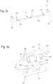
- eine isometrische Darstellung eines PV-Moduls mit Blick auf seine Rückseite in einem zweiten Ausführungsbeispiel;
- Figur 2b
- eine Detailansicht des PV-Moduls der
Figur 2a im Bereich einer Anschlussdose; - Figur 2c
- die Anschlussdose gemäß den
Figuren 2a, b separat in einer isometrischen Darstellung mit Blick auf ihre Unterseite; - Figur 3a
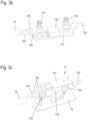
- eine isometrische Darstellung von Teilen einer Anschlussdose eines PV-Moduls vor einem Kontaktieren;
- Figur 3b
- eine isometrische Darstellung eines Kontaktelements gemäß Figur 3a mit Blick auf seine Unterseite; und
- Figur 3c
- die Anordnung gemäß
Figur 3a im kontaktierten Zustand. - In
Figur 1a ist ein PV-Modul 1 in einer isometrischen Darstellung wiedergegeben. Das PV-Modul 1 weist einen Rahmen 2 auf sowie die eigentliche Modulstruktur, die im Rahmen dieser Anmeldung auch als Schichtenaufbau oder Schichtenstapel bezeichnet wird. Von dieser Modulstruktur ist in der Darstellung derFigur 1a nur eine Rückseite 3 zu erkennen. - Bei dem PV-Modul 1 umfasst die Modulstruktur eine oder mehrere Zellanordnungen - hier konkret drei - die jeweils eine Mehrzahl von hier nicht einzeln erkennbaren PV-Zellen aufweisen, die jeweils in Form von zwei Strings angeordnet sind. Die Rückseite 3 des PV-Moduls 1 ist mit einer isolierenden Schicht abgedeckt, wobei diese isolierende Schicht an ausgewählten Stellen unterbrochen ist, um den Austritt von Anschlusskontakten der Zellanordnungen zu ermöglichen.
- Aufgrund der Modulstruktur sind bei dem PV-Modul 1 der
Figur 1a die Anschlusskontakte in Gruppen von jeweils zwei Kontakten pro Zellanordnung entlang einer Mittellinie des PV-Moduls 1 angeordnet. Die Mittellinie des PV-Moduls 1 verläuft parallel zu seinen (kürzeren) Querseiten und mittig im Hinblick auf die (längeren) Längsseiten des PV-Moduls 1, dessen Grundfläche rechteckig ist. - Entlang der genannten Mittellinie ist eine Anschlussanordnung 10 vorhanden, die in der
Figur 1b in einer Vergrößerung wiedergegeben ist. Die Anschlussanordnung 10 umfasst eine Anschlussdose 11 und zwei Anschlusskabel 14. - Anmeldungsgemäß erstreckt sich die Anschlussdose 11 über annähernd die gesamte Ausdehnung des PV-Moduls 1 in seiner Querrichtung, so dass von einer einzelnen Anschlussdose 11 alle Anschlusskontakte des PV-Moduls 1 abgedeckt werden und entsprechend innerhalb dieser einen Anschlussdose 11 kontaktiert werden. Die Anschlussdose 11 weist entsprechend ein durchgehendes und lang gestrecktes Gehäuse 111 auf. Dieses Gehäuse 111 ist in drei Kontaktbereichen 112, in denen die hier nicht sichtbaren Anschlusskontakte des PV-Moduls 1 liegen, verbreitert und erhöht sowie nach oben von jeweils einem Deckel 12 abgedeckt.
- In den
Figuren 2a und 2b ist ein weiteres Ausführungsbeispiel eines PV-Moduls 1 mit Anschlussanordnung 10 in gleicher Weise wie in denFiguren 1a und 1b dargestellt. Der Aufbau des PV-Moduls 1 und der Anschlussanordnung 10 entspricht im Wesentlichen dem des ersten Ausführungsbeispiels. Im Unterschied ist, wie insbesondere ausFigur 2b ersichtlich, die Anschlussdose 11 über die beiden äußeren Kontaktbereiche 112 durch verlängerte Endabschnitte 113 bis an den Rahmen 2 des PV-Moduls 1 herangeführt. - Bei beiden Ausführungsbeispielen ermöglicht es die lang gestreckte Anschlussdose 11 mit dem entsprechend geformten Gehäuse 111 eine Kontaktierung aller Anschlusskontakte des PV-Moduls 1 durch eine einzelne Anschlussdose 11. Entsprechend muss auch nur diese eine Anschlussdose 11 auf die Rückseite 3 des PV-Moduls 1 aufmontiert werden. Das beschleunigt die Kontaktierung und damit die Herstellung des PV-Moduls 1.
- Darüber hinaus stellt die Anschlussdose 11 aufgrund ihrer Erstreckung über annähernd (
Figur 1a, 1b ) bzw. die gesamte Breite (Figur 2a, 2b ) des PV-Moduls 1 eine Verstärkung und Stabilisierung des PV-Moduls 1 dar. Das PV-Modul 1 kann durch die Stabilisierung durch die Anschlussdose 11 beispielsweise eine höhere Schnee- oder Windlast tragen. Neben den positiven Eigenschaften der Stabilisierung und Verstärkung im Betrieb ist eine höhere Steifigkeit des PV-Moduls 1 auch für Produktion, Transport und Handling bei der Montage vorteilhaft. - In
Figur 2c ist die Anschlussanordnung 10, d.h. die Anordnung aus Anschlussdose 11 und Anschlusskabeln 14, separat vom PV-Modul 1 mit Blick auf ihre Unterseite dargestellt. In dieser Darstellung zeigt sich, dass das Gehäuse 111 an seiner Unterseite 114 eine große Klebefläche bereitstellt, mit der die Anschlussdose 11 auf die Rückseite 3 des PV-Moduls 1 aufgeklebt und damit auch abgedichtet wird. Die große Klebefläche führt auch zu einer großen Belastbarkeit der Verbindung zwischen Anschlussdose 11 und Rückseite 3 des PV-Moduls 1, was beispielsweise verhindert, dass Zugkräfte am Anschlusskabel 14 die Anschlussdose 11 ungewollt von der Rückseite 3 des PV-Moduls 1 lösen. - Weiter ist in
Figur 2c erkennbar, dass das Gehäuse 111 einen durchgehenden Hohlraum bereitstellt, der sich über die drei Kontaktbereiche 112 erstreckt. Falls eine Kontaktierung der Zellanordnung untereinander nicht innerhalb des PV-Moduls 1 vorgenommen ist, kann der Hohlraum, der zwischen zwei Kontaktbereichen 112 im Gehäuse 111 vorhanden ist, genutzt werden, um eine elektrische Verbindung zwischen den Anschlusskontakten der verschiedenen Zellanordnungen innerhalb der Anschlussdose 11 umzusetzen. - Die
Figuren 3a-c zeigen jeweils den Bereich zweier Anschlusskontakte 4 auf der Rückseite 3 eines PV-Moduls 1. - In der
Figur 3a sind die beiden Anschlusskontakte 4 einer Zellanordnung zu erkennen, die in Form von Anschlusslaschen von der Rückseite 3 des PV-Moduls 1 hochstehen. Über die Anschlusskontakte 4 wird ein Kontaktträger 15 gesteckt, der mit seiner Unterseite 151 auf die Rückseite 3 des PV-Moduls 1 aufgeklebt wird. Der Kontaktträger 15 weist im Bereich der Anschlusskontakte 4 Kontaktführungsnuten 152 auf, die die Anschlusskontakte 4 führen und ein Abbiegen der Anschlusskontakte 4 zur Seite hin verhindern. - In dem dargestellten Ausführungsbeispiel ist ein Kontaktträger 15 für jeweils zwei Anschlusskontakte 4 vorgesehen. Bei den in den
Figuren 1a bis 2c gezeigten PV-Modulen 1 würden entsprechend der Anzahl von drei Zellanordnungen drei Kontaktträger 15 eingesetzt. In alternativen Ausführungen kann auch ein einzelner länglicher Kontaktträger eingesetzt werden, der sich über die Anschlussbereiche aller Zellanordnungen erstreckt und alle Anschlusskontakte 4 des PV-Moduls 1 aufnimmt, z.B. durch eine entsprechende Anzahl von Kontaktführungsnuten 152. - Auf die oder den Kontaktträger 15 wird dann das Gehäuse 111 der Anschlussdose 11 aufgesetzt, wobei das Gehäuse 111 die Kontaktträger 15 vollständig umgibt. Die Unterseite 114 des Gehäuses 111 liegt, wie im Zusammenhang mit der
Figur 2c beschrieben ist, auf der Rückseite 3 des PV-Moduls 1 auf und ist mit diesem verklebt. - Zur Kontaktierung von jeweils zwei Anschlusskontakten 4 einer Zellanordnung ist jeweils ein Kontaktelement 13 vorgesehen, das bereits in das Gehäuse 111 eingesetzt ist. In der
Figur 3a ist ein solches Kontaktelement 13 vor dem Aufsetzen auf die Anschlusskontakte 4 bzw. den Kontaktträger 15 wiedergegeben. Dabei ist das Gehäuse 111 der Anschlussdose 11 nicht gezeigt, damit der Kontaktträger 15 und das Kontaktelement 13 sichtbar sind. - Das Kontaktelement 13 ist beispielsweise auf Basis eines Stanzgitters 131 ausgebildet. Am Stanzgitter 131 sind seitlich Anschlüsse 132 ausgeformt, wobei an einem der Anschlüsse 132 eines der Anschlusskabel 14 befestigt ist, beispielsweise in einem Punktschweißvorgang. An dem gegenüberliegenden Anschluss 132 kann ein Verbindungskabel angeschlossen sein, das zum nächsten Kontaktbereich 112 führt. Falls eine interne Kontaktierung im PV-Modul 1 zwischen den Zellanordnungen vorgesehen ist, kann der zweite Anschluss 132 auch offenbleiben.
- Weiter sind am Kontaktelement 13 zwei Kontakte zur Kontaktierung der Anschlusskontakte 4 vorhanden, die vorliegend als Kontakttulpen 133 ausgeführt sind. Zudem ist eine Bypass-Diode 134 montiert, die elektrisch zwischen den beiden Kontakttulpen 133 verschaltet ist, so dass sie parallel zu den Anschlusskontakten 4 und damit parallel zur Zellanordnung geschaltet ist.
- In
Figur 3b ist das Kontaktelement 13 mit Blick auf seiner Unterseite nochmals separat wiedergegeben. Um die Kontakttulpen 133 und die Bypass-Diode 134 auf dem Stanzgitter 131 montieren, insbesondere verschweißen bzw. verlöten zu können, liegt das Stanzgitter 131 zunächst noch einteilig vor. Die seitlich Anschlüsse 132 sind daher zunächst noch elektrisch miteinander verbunden. Nach der Montage der Kontakttulpen 133 und der Bypass-Diode 134 wird diese Verbindung an Trennstellen 135 aufgetrennt. - Eine Befestigung der montierten Kontaktelemente 13 in der Anschlussdose 11 kann durch im Gehäuse 111 der Anschlussdose 11 ausgebildete Rastelemente erfolgen. Alternativ oder zusätzlich können heißverprägte Halteelemente des Gehäuses 111 eingesetzt werden. Dabei ist es denkbar, dass die Öffnung der Trennstellen 135 in einem Arbeitsschritt mit dem Heißverprägen erfolgt.
- In
Figur 3c ist die Anordnung aus derFigur 3a nochmals in einem Montagezustand wiedergegeben, in dem das Kontaktelement 13 auf die Anschlusskontakte 4 aufgedrückt ist, so dass die Kontakttulpen 133 die Anschlusskontakte 4 kontaktieren. - Bevorzugt sind, wie zuvor beschrieben, die Kontaktelemente 13 bereits in die Anschlussdose 11 integriert. Es ist alternativ auch möglich, die Kontaktelemente 13 wie in der
Figur 3c sichtbar zunächst ohne Anschlussdose auf die Kontaktträger 15 aufzusetzen und dann die Anschlussdose 11 überzustülpen. - In jedem Fall ist durch die Verklebung der Anschlussdose 11 mit ihrer Unterseite 114 auf der Rückseite 3 des PV-Moduls 1 und das Verschließen des Kontaktbereichs 112 durch den Deckel 12 der im Gehäuse 111 der Anschlussdose 11 ausgebildete Hohlraum hermetisch so abgedichtet, dass beispielsweise ein Vergießen dieses Hohlraums nicht erforderlich ist. Vorteilhaft kann durch Öffnen eines Deckels 12 dann das Kontaktelement 13 ausgetauscht werden, beispielsweise wenn an der betreffenden Bypass-Diode 134 ein Defekt aufgetreten ist. Falls ein Austausch von Elementen nicht vorgesehen ist, kann der Deckel 12 auch integral mit der Anschlussdose 11 ausgebildet sein, die Anschlussdose 11 also mit Ausnahme der Öffnung an ihrer Unterseite 114 vollständig geschlossen sein.
-
- 1
- Photovoltaik-Modul (PV-Modul)
- 2
- Rahmen
- 3
- Rückseite
- 4
- Anschlusskontakt
- 10
- Anschlussanordnung
- 11
- Anschlussdose
- 111
- Gehäuse
- 112
- Kontaktbereich
- 113
- Endabschnitt
- 114
- Unterseite
- 12
- Deckel
- 13
- Kontaktelement
- 131
- Stanzgitter
- 132
- Anschluss
- 133
- Kontakttulpe
- 134
- Bypass-Diode
- 14
- Anschlusskabel
- 15
- Kontaktträger
- 151
- Unterseite
- 152
- Kontaktführungsnut
Claims (13)
- Photovoltaikmodul (1) mit mindestens zwei Zellanordnungen, die extern an Anschlusskontakten (4) kontaktierbar sind, die in den Zellanordnungen zugeordneten Gruppen von jeweils zwei Anschlusskontakten (4) entlang einer Linie an der Rückseite des Photovoltaikmoduls (1) angeordnet sind, dadurch gekennzeichnet, dass genau eine Anschlussdose (11) auf einer Rückseite (3) des Photovoltaikmodul (1) angeordnet ist, die ein Gehäuse (111) aufweist, das zu der Rückseite (3) hin mindestens eine Öffnung zur Durchführung der Anschlusskontakt (4) aufweist, wobei das Gehäuse (111) alle Anschlusskontakte (4) des Photovoltaikmoduls (1) überdeckt.
- Photovoltaikmodul (1) nach Anspruch 1, aufweisend eine rechteckige Grundfläche, wobei die Linie, entlang derer die Anschlusskontakte (4) angeordnet sind, parallel zu einer der Seitenkanten des Photovoltaikmodul (1) verläuft und wobei das Gehäuse (111) der Anschlussdose (11) eine Länge aufweist, die größer als 66 % und bevorzugt größer als 80 % der Länge der Seitenkante ist.
- Photovoltaikmodul (1) nach Anspruch 2, aufweisend einen äußeren Rahmen (2) aus Metallprofilen, wobei das Gehäuse (111) der Anschlussdose (11) mit mindestens einem Endabschnitt (113) bis an den Rahmen (2) reicht.
- Photovoltaikmodul (1) nach Anspruch 3, wobei das Gehäuse (111) der Anschlussdose (11) auf beiden Seiten mit Endabschnitten (113) bis an den Rahmen (2) reicht.
- Photovoltaikmodul (1) nach einem der Ansprüche 1 bis 4, wobei das Gehäuse (111) eine Unterseite (114) aufweist, die als Klebefläche dient, mit der die Anschlussdose (11) auf die Rückseite (3) aufgeklebt ist.
- Anschlussdose (11) für ein Photovoltaikmodul (1), das mindestens zwei Zellanordnungen aufweist, die extern an mindestens jeweils zwei Anschlusskontakten (4) kontaktierbar sind, wobei die Anschlussdose (11) ein Gehäuse (111) aufweist, das mindestens eine Öffnung zur Durchführung der Anschlusskontakte (4) aufweist, und wobei im Gehäuse (111) mindestens vier Kontakte zur Kontaktierung der Anschlusskontakte (4) angeordnet sind, dadurch gekennzeichnet, dass
das Gehäuse (111) eine langgestreckte Grundform aufweist, wobei alle Anschlusskontakte (4) in einer Linie entlang einer Längsrichtung des Gehäuses (111) angeordnet sind. - Anschlussdose (11) nach Anspruch 6, bei der die Kontakte im Gehäuse (111) in Kontaktbereichen (112) angeordnet sind.
- Anschlussdose (11) nach Anspruch 7, bei der das Gehäuse (111) in den Kontaktbereichen (112) auch nach oben jeweils eine Öffnung aufweist, die mit einem Deckel (12) verschließbar ist.
- Anschlussdose (11) nach einem der Ansprüche 6 bis 8, aufweisend mindestens einen Kontaktträger (13), der mindestens zwei Kontakte trägt.
- Anschlussdose (11) nach Anspruch 9, bei der der mindestens eine Kontaktträger (13) durch ein Stanzgitter (131) gebildet ist.
- Anschlussdose (11) nach Anspruch 9 oder 10, bei der der mindestens ein Kontaktträger (13) alle Kontakte zur Kontaktierung der Anschlusskontakte (4) trägt.
- Anschlussdose (11) nach einem der Ansprüche 6 bis 11, bei der die Kontakte Kontakttulpen (133) sind.
- Anschlussdose (11) nach einem der Ansprüche 9 bis 12, bei der an dem mindestens einen Kontaktträger (13) mindestens eine Bypass-Diode (134) angeordnet ist, die parallel zu zwei Kontakten geschaltet ist.
Applications Claiming Priority (1)
| Application Number | Priority Date | Filing Date | Title |
|---|---|---|---|
| DE102022103543.3A DE102022103543A1 (de) | 2022-02-15 | 2022-02-15 | Photovoltaikmodul und Anschlussdose für ein Photovoltaikmodul |
Publications (2)
| Publication Number | Publication Date |
|---|---|
| EP4228153A1 true EP4228153A1 (de) | 2023-08-16 |
| EP4228153B1 EP4228153B1 (de) | 2025-04-23 |
Family
ID=85175902
Family Applications (1)
| Application Number | Title | Priority Date | Filing Date |
|---|---|---|---|
| EP23155197.9A Active EP4228153B1 (de) | 2022-02-15 | 2023-02-06 | Photovoltaikmodul und anschlussdose für ein photovoltaikmodul |
Country Status (4)
| Country | Link |
|---|---|
| US (1) | US20230261611A1 (de) |
| EP (1) | EP4228153B1 (de) |
| CN (1) | CN116614078A (de) |
| DE (1) | DE102022103543A1 (de) |
Families Citing this family (1)
| Publication number | Priority date | Publication date | Assignee | Title |
|---|---|---|---|---|
| DE102024106442A1 (de) * | 2024-03-06 | 2025-09-11 | Weidmüller Interface GmbH & Co. KG | Photovoltaikmodul mit mindestens zwei Zellanordnungen und einer Anschlussdose und Verfahren zum Verbinden einer Zellanordnung mit Kontaktelementen einer Anschlussdose |
Citations (4)
| Publication number | Priority date | Publication date | Assignee | Title |
|---|---|---|---|---|
| US20100075531A1 (en) * | 2008-09-22 | 2010-03-25 | Weidmuller Interface Gmbh & Co. Kg | Electrical connector arrangement for flat conductors |
| US20110183531A1 (en) * | 2008-06-12 | 2011-07-28 | Anton Gensler Gmbh | Junction box for photovoltaic modules |
| DE102013211167A1 (de) * | 2013-06-14 | 2014-12-18 | SolarWorld Industries Thüringen GmbH | Solarmodulrahmen mit einer Stabilisierungsschiene, Solarmodul mit einem Solarmodulrahmen mit einer Stabilisierungsschiene und Anschlusseinheit für einen Solarmodulrahmen |
| US20160141435A1 (en) | 2013-07-05 | 2016-05-19 | Rec Solar Pte. Ltd. | Solar cell assembly |
Family Cites Families (2)
| Publication number | Priority date | Publication date | Assignee | Title |
|---|---|---|---|---|
| WO2010054841A2 (de) | 2008-11-17 | 2010-05-20 | Hirschmann Automation And Control Gmbh | Photovoltaik-komponenten |
| DE102011052928A1 (de) | 2011-02-03 | 2012-08-09 | Günther Spelsberg GmbH & Co. KG | Anordnung mit einem Solarzellenmodul, einer Anschlussdose, einem Anschlussstecker und einer Anschlussleitung |
-
2022
- 2022-02-15 DE DE102022103543.3A patent/DE102022103543A1/de active Pending
-
2023
- 2023-02-06 EP EP23155197.9A patent/EP4228153B1/de active Active
- 2023-02-14 CN CN202310114608.6A patent/CN116614078A/zh active Pending
- 2023-02-14 US US18/168,858 patent/US20230261611A1/en not_active Abandoned
Patent Citations (4)
| Publication number | Priority date | Publication date | Assignee | Title |
|---|---|---|---|---|
| US20110183531A1 (en) * | 2008-06-12 | 2011-07-28 | Anton Gensler Gmbh | Junction box for photovoltaic modules |
| US20100075531A1 (en) * | 2008-09-22 | 2010-03-25 | Weidmuller Interface Gmbh & Co. Kg | Electrical connector arrangement for flat conductors |
| DE102013211167A1 (de) * | 2013-06-14 | 2014-12-18 | SolarWorld Industries Thüringen GmbH | Solarmodulrahmen mit einer Stabilisierungsschiene, Solarmodul mit einem Solarmodulrahmen mit einer Stabilisierungsschiene und Anschlusseinheit für einen Solarmodulrahmen |
| US20160141435A1 (en) | 2013-07-05 | 2016-05-19 | Rec Solar Pte. Ltd. | Solar cell assembly |
Also Published As
| Publication number | Publication date |
|---|---|
| EP4228153B1 (de) | 2025-04-23 |
| US20230261611A1 (en) | 2023-08-17 |
| CN116614078A (zh) | 2023-08-18 |
| DE102022103543A1 (de) | 2023-08-17 |
Similar Documents
| Publication | Publication Date | Title |
|---|---|---|
| DE102007051134B4 (de) | Anschluss- und Verbindungsdose für ein Solarmodul | |
| DE102008003448B4 (de) | Anschlußdose, Verwendung, Solarpaneel, Kontaktelement, und Verfahren | |
| DE69229030T2 (de) | Solarzellenmodul | |
| DE60119610T2 (de) | Elektrisches Verbindungsgehäuse | |
| DE102008028462A1 (de) | Elektrische Anschluss- und Verbindungsdose für ein Solarzellenmodul | |
| EP2115838A1 (de) | Anschluss- und verbindungsdose für ein solarmodul | |
| EP2115839A1 (de) | Anschluss- und verbindungsdose für ein solarmodul | |
| DE102007035883A1 (de) | Rückkontaktsolarzelle und Solarmodul mit reduzierten Serienwiderständen | |
| DE112006002823T5 (de) | Anschlußkasten für Solarbatteriemodul | |
| DE102011077224A1 (de) | Solarmodul und Photovoltaik-Anlage | |
| DE102008039933B4 (de) | Verbindungsvorrichtung zur Verbindung eines elektrischen Leiters mit einem Solarmodul und Verfahren zu ihrer Herstellung, sowie Solarmodul mit einer solchen Verbindungsvorrichtung | |
| EP4228153B1 (de) | Photovoltaikmodul und anschlussdose für ein photovoltaikmodul | |
| DE102007052722A1 (de) | Anordnung mit einem Solarzellenmodul und einem Rahmen | |
| EP4233098B1 (de) | Solarzellenmodul | |
| DE102020128080B4 (de) | Solarzellenmodul | |
| DE102022107526A1 (de) | Photovoltaikmodul und Anschlussdose für ein Photovoltaikmodul | |
| DE102009040568A1 (de) | Anschlußdose, Verwendung, Solarpaneel und Verfahren | |
| DE102010056591A1 (de) | Photovoltaikmodul und Solaranlage mit derartigen Photovoltaikmodulen | |
| WO2023099771A1 (de) | Solarzellenmodul | |
| DE102012006033A1 (de) | Elektrische Anschluss- und Verbindungsvorrichtung für ein Solarzellenmodul | |
| DE102024106441A1 (de) | Bypass-Element und Photovoltaikmodul mit mindestens einem Bypass- Element | |
| DE102008040332A1 (de) | Rückseitenkontaktierte Solarzelle | |
| DE102024106442A1 (de) | Photovoltaikmodul mit mindestens zwei Zellanordnungen und einer Anschlussdose und Verfahren zum Verbinden einer Zellanordnung mit Kontaktelementen einer Anschlussdose | |
| WO2023025631A1 (de) | Photovoltaikmodul und anschlussanordnung für ein photovoltaikmodul | |
| EP4160908A1 (de) | Photovoltaikmodul und anschlussanordnung für ein photovoltaikmodul |
Legal Events
| Date | Code | Title | Description |
|---|---|---|---|
| PUAI | Public reference made under article 153(3) epc to a published international application that has entered the european phase |
Free format text: ORIGINAL CODE: 0009012 |
|
| STAA | Information on the status of an ep patent application or granted ep patent |
Free format text: STATUS: THE APPLICATION HAS BEEN PUBLISHED |
|
| AK | Designated contracting states |
Kind code of ref document: A1 Designated state(s): AL AT BE BG CH CY CZ DE DK EE ES FI FR GB GR HR HU IE IS IT LI LT LU LV MC ME MK MT NL NO PL PT RO RS SE SI SK SM TR |
|
| STAA | Information on the status of an ep patent application or granted ep patent |
Free format text: STATUS: REQUEST FOR EXAMINATION WAS MADE |
|
| 17P | Request for examination filed |
Effective date: 20240216 |
|
| RBV | Designated contracting states (corrected) |
Designated state(s): AL AT BE BG CH CY CZ DE DK EE ES FI FR GB GR HR HU IE IS IT LI LT LU LV MC ME MK MT NL NO PL PT RO RS SE SI SK SM TR |
|
| GRAP | Despatch of communication of intention to grant a patent |
Free format text: ORIGINAL CODE: EPIDOSNIGR1 |
|
| STAA | Information on the status of an ep patent application or granted ep patent |
Free format text: STATUS: GRANT OF PATENT IS INTENDED |
|
| RIC1 | Information provided on ipc code assigned before grant |
Ipc: H02S 40/34 20140101AFI20241122BHEP |
|
| INTG | Intention to grant announced |
Effective date: 20241218 |
|
| GRAS | Grant fee paid |
Free format text: ORIGINAL CODE: EPIDOSNIGR3 |
|
| P01 | Opt-out of the competence of the unified patent court (upc) registered |
Free format text: CASE NUMBER: APP_7255/2025 Effective date: 20250212 |
|
| GRAA | (expected) grant |
Free format text: ORIGINAL CODE: 0009210 |
|
| STAA | Information on the status of an ep patent application or granted ep patent |
Free format text: STATUS: THE PATENT HAS BEEN GRANTED |
|
| AK | Designated contracting states |
Kind code of ref document: B1 Designated state(s): AL AT BE BG CH CY CZ DE DK EE ES FI FR GB GR HR HU IE IS IT LI LT LU LV MC ME MK MT NL NO PL PT RO RS SE SI SK SM TR |
|
| REG | Reference to a national code |
Ref country code: GB Ref legal event code: FG4D Free format text: NOT ENGLISH |
|
| REG | Reference to a national code |
Ref country code: CH Ref legal event code: EP |
|
| REG | Reference to a national code |
Ref country code: DE Ref legal event code: R096 Ref document number: 502023000854 Country of ref document: DE |
|
| REG | Reference to a national code |
Ref country code: IE Ref legal event code: FG4D Free format text: LANGUAGE OF EP DOCUMENT: GERMAN |
|
| REG | Reference to a national code |
Ref country code: NL Ref legal event code: MP Effective date: 20250423 |
|
| PG25 | Lapsed in a contracting state [announced via postgrant information from national office to epo] |
Ref country code: NL Free format text: LAPSE BECAUSE OF FAILURE TO SUBMIT A TRANSLATION OF THE DESCRIPTION OR TO PAY THE FEE WITHIN THE PRESCRIBED TIME-LIMIT Effective date: 20250423 |
|
| PG25 | Lapsed in a contracting state [announced via postgrant information from national office to epo] |
Ref country code: FI Free format text: LAPSE BECAUSE OF FAILURE TO SUBMIT A TRANSLATION OF THE DESCRIPTION OR TO PAY THE FEE WITHIN THE PRESCRIBED TIME-LIMIT Effective date: 20250423 Ref country code: PT Free format text: LAPSE BECAUSE OF FAILURE TO SUBMIT A TRANSLATION OF THE DESCRIPTION OR TO PAY THE FEE WITHIN THE PRESCRIBED TIME-LIMIT Effective date: 20250825 Ref country code: ES Free format text: LAPSE BECAUSE OF FAILURE TO SUBMIT A TRANSLATION OF THE DESCRIPTION OR TO PAY THE FEE WITHIN THE PRESCRIBED TIME-LIMIT Effective date: 20250423 |
|
| REG | Reference to a national code |
Ref country code: LT Ref legal event code: MG9D |
|
| PG25 | Lapsed in a contracting state [announced via postgrant information from national office to epo] |
Ref country code: GR Free format text: LAPSE BECAUSE OF FAILURE TO SUBMIT A TRANSLATION OF THE DESCRIPTION OR TO PAY THE FEE WITHIN THE PRESCRIBED TIME-LIMIT Effective date: 20250724 Ref country code: NO Free format text: LAPSE BECAUSE OF FAILURE TO SUBMIT A TRANSLATION OF THE DESCRIPTION OR TO PAY THE FEE WITHIN THE PRESCRIBED TIME-LIMIT Effective date: 20250723 |
|
| PG25 | Lapsed in a contracting state [announced via postgrant information from national office to epo] |
Ref country code: PL Free format text: LAPSE BECAUSE OF FAILURE TO SUBMIT A TRANSLATION OF THE DESCRIPTION OR TO PAY THE FEE WITHIN THE PRESCRIBED TIME-LIMIT Effective date: 20250423 |
|
| PG25 | Lapsed in a contracting state [announced via postgrant information from national office to epo] |
Ref country code: BG Free format text: LAPSE BECAUSE OF FAILURE TO SUBMIT A TRANSLATION OF THE DESCRIPTION OR TO PAY THE FEE WITHIN THE PRESCRIBED TIME-LIMIT Effective date: 20250423 |
|
| PG25 | Lapsed in a contracting state [announced via postgrant information from national office to epo] |
Ref country code: HR Free format text: LAPSE BECAUSE OF FAILURE TO SUBMIT A TRANSLATION OF THE DESCRIPTION OR TO PAY THE FEE WITHIN THE PRESCRIBED TIME-LIMIT Effective date: 20250423 |
|
| PG25 | Lapsed in a contracting state [announced via postgrant information from national office to epo] |
Ref country code: RS Free format text: LAPSE BECAUSE OF FAILURE TO SUBMIT A TRANSLATION OF THE DESCRIPTION OR TO PAY THE FEE WITHIN THE PRESCRIBED TIME-LIMIT Effective date: 20250723 |
|
| PG25 | Lapsed in a contracting state [announced via postgrant information from national office to epo] |
Ref country code: IS Free format text: LAPSE BECAUSE OF FAILURE TO SUBMIT A TRANSLATION OF THE DESCRIPTION OR TO PAY THE FEE WITHIN THE PRESCRIBED TIME-LIMIT Effective date: 20250823 |
|
| PG25 | Lapsed in a contracting state [announced via postgrant information from national office to epo] |
Ref country code: LV Free format text: LAPSE BECAUSE OF FAILURE TO SUBMIT A TRANSLATION OF THE DESCRIPTION OR TO PAY THE FEE WITHIN THE PRESCRIBED TIME-LIMIT Effective date: 20250423 |
|
| PG25 | Lapsed in a contracting state [announced via postgrant information from national office to epo] |
Ref country code: DK Free format text: LAPSE BECAUSE OF FAILURE TO SUBMIT A TRANSLATION OF THE DESCRIPTION OR TO PAY THE FEE WITHIN THE PRESCRIBED TIME-LIMIT Effective date: 20250423 Ref country code: SM Free format text: LAPSE BECAUSE OF FAILURE TO SUBMIT A TRANSLATION OF THE DESCRIPTION OR TO PAY THE FEE WITHIN THE PRESCRIBED TIME-LIMIT Effective date: 20250423 |
|
| PG25 | Lapsed in a contracting state [announced via postgrant information from national office to epo] |
Ref country code: CZ Free format text: LAPSE BECAUSE OF FAILURE TO SUBMIT A TRANSLATION OF THE DESCRIPTION OR TO PAY THE FEE WITHIN THE PRESCRIBED TIME-LIMIT Effective date: 20250423 |
|
| PG25 | Lapsed in a contracting state [announced via postgrant information from national office to epo] |
Ref country code: EE Free format text: LAPSE BECAUSE OF FAILURE TO SUBMIT A TRANSLATION OF THE DESCRIPTION OR TO PAY THE FEE WITHIN THE PRESCRIBED TIME-LIMIT Effective date: 20250423 |
|
| REG | Reference to a national code |
Ref country code: DE Ref legal event code: R097 Ref document number: 502023000854 Country of ref document: DE |
|
| PG25 | Lapsed in a contracting state [announced via postgrant information from national office to epo] |
Ref country code: SK Free format text: LAPSE BECAUSE OF FAILURE TO SUBMIT A TRANSLATION OF THE DESCRIPTION OR TO PAY THE FEE WITHIN THE PRESCRIBED TIME-LIMIT Effective date: 20250423 |
|
| PG25 | Lapsed in a contracting state [announced via postgrant information from national office to epo] |
Ref country code: IT Free format text: LAPSE BECAUSE OF FAILURE TO SUBMIT A TRANSLATION OF THE DESCRIPTION OR TO PAY THE FEE WITHIN THE PRESCRIBED TIME-LIMIT Effective date: 20250423 |
|
| PLBE | No opposition filed within time limit |
Free format text: ORIGINAL CODE: 0009261 |
|
| STAA | Information on the status of an ep patent application or granted ep patent |
Free format text: STATUS: NO OPPOSITION FILED WITHIN TIME LIMIT |
|
| REG | Reference to a national code |
Ref country code: CH Ref legal event code: L10 Free format text: ST27 STATUS EVENT CODE: U-0-0-L10-L00 (AS PROVIDED BY THE NATIONAL OFFICE) Effective date: 20260304 |
|
| 26N | No opposition filed |
Effective date: 20260126 |
|
| PGFP | Annual fee paid to national office [announced via postgrant information from national office to epo] |
Ref country code: DE Payment date: 20260218 Year of fee payment: 4 |
|
| PGFP | Annual fee paid to national office [announced via postgrant information from national office to epo] |
Ref country code: AT Payment date: 20260301 Year of fee payment: 4 |