EP4228084A1 - Method for re-injecting electrolyte, and secondary battery enabling electrolyte re-injection - Google Patents
Method for re-injecting electrolyte, and secondary battery enabling electrolyte re-injection Download PDFInfo
- Publication number
- EP4228084A1 EP4228084A1 EP21911517.7A EP21911517A EP4228084A1 EP 4228084 A1 EP4228084 A1 EP 4228084A1 EP 21911517 A EP21911517 A EP 21911517A EP 4228084 A1 EP4228084 A1 EP 4228084A1
- Authority
- EP
- European Patent Office
- Prior art keywords
- polymer layer
- functional hole
- aluminium sheet
- electrolyte
- pouch
- Prior art date
- Legal status (The legal status is an assumption and is not a legal conclusion. Google has not performed a legal analysis and makes no representation as to the accuracy of the status listed.)
- Granted
Links
Images



Classifications
-
- H—ELECTRICITY
- H01—ELECTRIC ELEMENTS
- H01M—PROCESSES OR MEANS, e.g. BATTERIES, FOR THE DIRECT CONVERSION OF CHEMICAL ENERGY INTO ELECTRICAL ENERGY
- H01M50/00—Constructional details or processes of manufacture of the non-active parts of electrochemical cells other than fuel cells, e.g. hybrid cells
- H01M50/10—Primary casings; Jackets or wrappings
- H01M50/102—Primary casings; Jackets or wrappings characterised by their shape or physical structure
- H01M50/105—Pouches or flexible bags
-
- H—ELECTRICITY
- H01—ELECTRIC ELEMENTS
- H01M—PROCESSES OR MEANS, e.g. BATTERIES, FOR THE DIRECT CONVERSION OF CHEMICAL ENERGY INTO ELECTRICAL ENERGY
- H01M50/00—Constructional details or processes of manufacture of the non-active parts of electrochemical cells other than fuel cells, e.g. hybrid cells
- H01M50/10—Primary casings; Jackets or wrappings
- H01M50/116—Primary casings; Jackets or wrappings characterised by the material
- H01M50/117—Inorganic material
- H01M50/119—Metals
-
- H—ELECTRICITY
- H01—ELECTRIC ELEMENTS
- H01M—PROCESSES OR MEANS, e.g. BATTERIES, FOR THE DIRECT CONVERSION OF CHEMICAL ENERGY INTO ELECTRICAL ENERGY
- H01M50/00—Constructional details or processes of manufacture of the non-active parts of electrochemical cells other than fuel cells, e.g. hybrid cells
- H01M50/10—Primary casings; Jackets or wrappings
- H01M50/116—Primary casings; Jackets or wrappings characterised by the material
- H01M50/121—Organic material
-
- H—ELECTRICITY
- H01—ELECTRIC ELEMENTS
- H01M—PROCESSES OR MEANS, e.g. BATTERIES, FOR THE DIRECT CONVERSION OF CHEMICAL ENERGY INTO ELECTRICAL ENERGY
- H01M50/00—Constructional details or processes of manufacture of the non-active parts of electrochemical cells other than fuel cells, e.g. hybrid cells
- H01M50/10—Primary casings; Jackets or wrappings
- H01M50/116—Primary casings; Jackets or wrappings characterised by the material
- H01M50/124—Primary casings; Jackets or wrappings characterised by the material having a layered structure
- H01M50/126—Primary casings; Jackets or wrappings characterised by the material having a layered structure comprising three or more layers
-
- H—ELECTRICITY
- H01—ELECTRIC ELEMENTS
- H01M—PROCESSES OR MEANS, e.g. BATTERIES, FOR THE DIRECT CONVERSION OF CHEMICAL ENERGY INTO ELECTRICAL ENERGY
- H01M50/00—Constructional details or processes of manufacture of the non-active parts of electrochemical cells other than fuel cells, e.g. hybrid cells
- H01M50/10—Primary casings; Jackets or wrappings
- H01M50/116—Primary casings; Jackets or wrappings characterised by the material
- H01M50/124—Primary casings; Jackets or wrappings characterised by the material having a layered structure
- H01M50/126—Primary casings; Jackets or wrappings characterised by the material having a layered structure comprising three or more layers
- H01M50/129—Primary casings; Jackets or wrappings characterised by the material having a layered structure comprising three or more layers with two or more layers of only organic material
-
- H—ELECTRICITY
- H01—ELECTRIC ELEMENTS
- H01M—PROCESSES OR MEANS, e.g. BATTERIES, FOR THE DIRECT CONVERSION OF CHEMICAL ENERGY INTO ELECTRICAL ENERGY
- H01M50/00—Constructional details or processes of manufacture of the non-active parts of electrochemical cells other than fuel cells, e.g. hybrid cells
- H01M50/30—Arrangements for facilitating escape of gases
- H01M50/394—Gas-pervious parts or elements
-
- H—ELECTRICITY
- H01—ELECTRIC ELEMENTS
- H01M—PROCESSES OR MEANS, e.g. BATTERIES, FOR THE DIRECT CONVERSION OF CHEMICAL ENERGY INTO ELECTRICAL ENERGY
- H01M50/00—Constructional details or processes of manufacture of the non-active parts of electrochemical cells other than fuel cells, e.g. hybrid cells
- H01M50/60—Arrangements or processes for filling or topping-up with liquids; Arrangements or processes for draining liquids from casings
- H01M50/609—Arrangements or processes for filling with liquid, e.g. electrolytes
-
- H—ELECTRICITY
- H01—ELECTRIC ELEMENTS
- H01M—PROCESSES OR MEANS, e.g. BATTERIES, FOR THE DIRECT CONVERSION OF CHEMICAL ENERGY INTO ELECTRICAL ENERGY
- H01M50/00—Constructional details or processes of manufacture of the non-active parts of electrochemical cells other than fuel cells, e.g. hybrid cells
- H01M50/60—Arrangements or processes for filling or topping-up with liquids; Arrangements or processes for draining liquids from casings
- H01M50/609—Arrangements or processes for filling with liquid, e.g. electrolytes
- H01M50/627—Filling ports
- H01M50/636—Closing or sealing filling ports, e.g. using lids
- H01M50/664—Temporary seals, e.g. for storage of instant batteries or seawater batteries
-
- H—ELECTRICITY
- H01—ELECTRIC ELEMENTS
- H01M—PROCESSES OR MEANS, e.g. BATTERIES, FOR THE DIRECT CONVERSION OF CHEMICAL ENERGY INTO ELECTRICAL ENERGY
- H01M50/00—Constructional details or processes of manufacture of the non-active parts of electrochemical cells other than fuel cells, e.g. hybrid cells
- H01M50/30—Arrangements for facilitating escape of gases
- H01M50/342—Non-re-sealable arrangements
- H01M50/3425—Non-re-sealable arrangements in the form of rupturable membranes or weakened parts, e.g. pierced with the aid of a sharp member
-
- Y—GENERAL TAGGING OF NEW TECHNOLOGICAL DEVELOPMENTS; GENERAL TAGGING OF CROSS-SECTIONAL TECHNOLOGIES SPANNING OVER SEVERAL SECTIONS OF THE IPC; TECHNICAL SUBJECTS COVERED BY FORMER USPC CROSS-REFERENCE ART COLLECTIONS [XRACs] AND DIGESTS
- Y02—TECHNOLOGIES OR APPLICATIONS FOR MITIGATION OR ADAPTATION AGAINST CLIMATE CHANGE
- Y02E—REDUCTION OF GREENHOUSE GAS [GHG] EMISSIONS, RELATED TO ENERGY GENERATION, TRANSMISSION OR DISTRIBUTION
- Y02E60/00—Enabling technologies; Technologies with a potential or indirect contribution to GHG emissions mitigation
- Y02E60/10—Energy storage using batteries
-
- Y—GENERAL TAGGING OF NEW TECHNOLOGICAL DEVELOPMENTS; GENERAL TAGGING OF CROSS-SECTIONAL TECHNOLOGIES SPANNING OVER SEVERAL SECTIONS OF THE IPC; TECHNICAL SUBJECTS COVERED BY FORMER USPC CROSS-REFERENCE ART COLLECTIONS [XRACs] AND DIGESTS
- Y02—TECHNOLOGIES OR APPLICATIONS FOR MITIGATION OR ADAPTATION AGAINST CLIMATE CHANGE
- Y02P—CLIMATE CHANGE MITIGATION TECHNOLOGIES IN THE PRODUCTION OR PROCESSING OF GOODS
- Y02P70/00—Climate change mitigation technologies in the production process for final industrial or consumer products
- Y02P70/50—Manufacturing or production processes characterised by the final manufactured product
Definitions
- the present invention relates to a pouch and a secondary battery comprising the same, and a manufacturing method thereof.
- the secondary battery is classified into a coin type battery, a cylindrical type battery, a prismatic type battery, and a pouch type battery.
- an electrode assembly mounted in a battery case has a stacked structure of an electrode and a separator, and is a power generation element that is chargeable and dischargeable.
- the electrode assembly may be roughly classified into a jelly-roll type, which is wound by interposing a separator between sheet-shaped positive and negative electrodes coated with an active material, a stacked type, in which multiple positive and negative electrodes are stacked in sequence with a separator interposed therebetween, and a stack and folding type, in which stacked type unit cells are wound using a long separation film.
- a pouch type battery which has a structure in which the stacked type or stack and folding type electrode assembly is embedded in a pouch type battery case of an aluminium laminate sheet, has gained much interest due to low manufacturing cost, small weight, easy change of shape, etc., and the usage thereof has gradually increased.
- Patent Document Korean Patent Publication No. 10-2014-0015647
- One aspect of the present invention is to provide a method for reinjecting an electrolyte, through which the electrolyte is easy to reinject, and a secondary battery capable of being reinjected with an electrolyte.
- a method for reinjecting an electrolyte is a method for reinjecting an electrolyte into a secondary battery in which an electrode assembly and an electrolyte are accommodated in a pouch.
- the pouch may comprise an aluminium sheet, in which a functional hole is formed, and a polymer layer stacked on the aluminium sheet.
- the method may comprise a reinjection process of injecting an additional electrolyte into the pouch through the functional hole by opening the functional hole, and a sealing process of sealing the functional hole after the reinjection process.
- a secondary battery capable of being reinjected with an electrolyte comprises an electrode assembly, in which electrodes and separators are alternately stacked to be combined with each other, and a pouch in which the electrode assembly is accommodated, wherein the pouch comprises an aluminium sheet and a polymer layer laminated with the aluminium sheet, a functional hole is formed in the aluminium sheet, and a coating part is provided on an inner circumferential surface of the functional hole in the aluminium sheet.
- the secondary battery uses the pouch, in which the polymer layer is stacked on the aluminium sheet having the functional hole formed therein, so that the electrolyte is easily reinjected through the functional hole.
- the gas inside the pouch may penetrate the polymer layer through the functional hole and be easily discharged to the outside.
- FIG. 1 is a plan view illustrating a secondary battery, which is applied to a method for reinjecting an electrolyte according to an embodiment of the present invention, in a state before an electrode assembly is accommodated in a pouch.
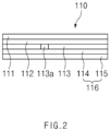
- FIG. 2 is a cross-sectional view taken along a line A-A' in FIG. 1 .
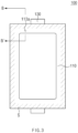
- FIG. 3 is a plan view illustrating the secondary battery, which is applied to the method for reinjecting an electrolyte according to an embodiment of the present invention.
- FIG. 4 is a cross-sectional view taken along a line B-B' in FIG. 3 .
- FIG. 5 is an enlarged cross-sectional view illustrating an area C in FIG. 4 .
- FIG. 6 is a cross-sectional view illustrating a concept of a reinjection process in the method for reinjecting an electrolyte according to an embodiment of the present invention.
- FIG. 7 is a cross-sectional view illustrating a concept of a sealing process in the method for reinjecting an electrolyte according to an embodiment of the present invention.
- FIGS. 6 and 7 are views illustrating respective examples of the concepts of the reinjection process and the sealing process by enlarging the area C in FIG. 4 .
- the method for reinjecting an electrolyte into a secondary battery is a method for reinjecting an electrolyte into a secondary battery 100 in which an electrode assembly 120 and an electrolyte are accommodated in a pouch 110.
- the pouch 110 comprises an aluminium sheet 113, in which a functional hole 113a is formed, and a polymer layer 111 and 116 stacked on the aluminium sheet 113.
- the method comprises a reinjection process of injecting an additional electrolyte into the pouch 110 through the functional hole 113a, and a sealing process of sealing the functional hole 113a after the reinjection process.
- the method for reinjecting an electrolyte into the secondary battery 100 is a method for reinjecting an electrolyte into the secondary battery 100 in which the electrode assembly 120, which is assembled by alternately stacking an electrode and a separator, and an electrolyte are accommodated in the pouch 110.
- the pouch 110 comprises the aluminium sheet 113, in which the functional hole 113a is formed, and the polymer layer 111 and 116 stacked on the aluminium sheet 113.
- a coating part 113b may be formed on an inner circumferential surface of the functional hole 113a in the aluminium sheet 113.
- the coating part 113b may comprise an insulating and chemically resistant material.
- the aluminum sheet 113 may be prevented from being oxidized due to contact of the electrolyte with the functional hole 113a portion, or electric current may be prevented from being conducted between the electrode assembly 120 and the aluminum sheet 113 through the functional hole 113a.
- the coating part 113b may comprise, for example, silicone, but the material of the coating part 113b is not necessarily limited thereto.
- an additional electrolyte is injected into the pouch 110 through the functional hole 113a.
- the functional hole 113a may be opened by forming a hole by means of a tool P in the portion, covering the functional hole 113a, of the polymer layer 111 and 116.
- the additional electrolyte may be injected through the functional hole 113a by piercing the portion, covering the functional hole 113a, of the polymer layer 111 and 116.
- the additional electrolyte may be injected through the functional hole 113a by penetrating an injection needle into the portion, covering the functional hole 113a, the polymer layer 111 and 116.
- the polymer layer 111 and 116 may comprise a first polymer layer 116 and a second polymer layer 111.
- the first polymer layer 116, the aluminium sheet 113, and the second polymer layer 111 may be stacked in the pouch 110 from the inside, in which the electrode assembly 120 is accommodated, to the outside.
- the first polymer layer 116 and the second polymer layer 111 may be formed on both surfaces of the aluminium sheet 113 to cover the functional hole 113a formed in the aluminium sheet 113.
- the first polymer layer 116 and the second polymer layer 111 may each comprise a polymer material.
- the first polymer layer 116 and the second polymer layer 111 which each comprise the polymer material permeable to gas such as CO and CO2, cover the functional hole 113a so that the internal gas may be discharged and the electrolyte may be prevented from being leaked through the functional hole 113a.
- the electrolyte may be injected into the pouch 110 through the functional hole 113a by opening portions, covering the functional hole 113a, of the first polymer layer 116 and the second polymer layer 111.
- a nylon layer 112 may be further stacked between the aluminium sheet 113 and the second polymer layer 111.
- the electrolyte may be injected into the pouch 110 through the functional hole 113a by opening portions, covering the functional hole 113a, of the first polymer layer 116, the nylon layer 112, and the second polymer layer 111.
- the first polymer layer 116 may be made of a polypropylene (PP) material
- the second polymer layer 111 may be made of a polyethylene terephthalate (PET) material.
- an inner layer, in which the electrode assembly 120 is accommodated may be made of a polypropylene (PP) material, and an outer layer, which faces the aluminium sheet 113, may be made of a polyphthalamide (PPa) material.
- the second polymer layer 111 may be made of a polyethylene terephthalate (PET) material.
- the functional hole 113a may be sealed after the reinjection process.
- the functional hole 113a may be sealed by sealing the portion, corresponding to the functional hole 113a, opened in the second polymer layer 111.
- the hole portion, corresponding to the functional hole 113a, opened in the second polymer layer 111 may be filled with a sealing material R to seal the functional hole 113a.
- the opened portion of the second polymer layer 111 may be sealed using a resin material R.
- the opened portion of the second polymer layer 111 may be sealed using the same material as the second polymer layer 111.
- the opened portion of the second polymer layer 111 is sealed using the same material as the second polymer layer 111, which comprises the polymer material permeable to gas such as CO and CO2, so that the internal gas may be discharged even though the injection portion is sealed through the sealing process after the electrolyte reinjection, and the electrolyte may be prevented from being leaked through the functional hole 113a.
- a secondary battery 100 capable of being reinjected with an electrolyte according to an embodiment of the present invention, comprises an electrode assembly 120, which is assembled by alternately stacking an electrode and a separator, and a pouch 110 in which the electrode assembly 120 is accommodated.
- the pouch 110 comprises an aluminium sheet 113 and a polymer layer 111 and 116 laminated with the aluminium sheet 113.
- a functional hole 113a is formed in the aluminium sheet 113.
- the secondary battery 100 capable of being reinjected with an electrolyte according to an embodiment of the present invention pertains to the secondary battery 100 to which the method for reinjecting an electrolyte according to the embodiment described above is applied.
- the content in common with the embodiment described above will be omitted or briefly provided, and the description of this embodiment will be focused on differences.
- the electrode assembly 120 is a power generation element chargeable and dischargeable, and is assembled by alternately stacking an electrode and a separator.
- the electrode may comprise a positive electrode and a negative electrode, and the positive electrode, the separator and the negative electrode may be alternately disposed.
- the electrode assembly 120 may further comprise an electrode lead 130 connected to an end of the electrode.
- the electrode assembly 120 may be electrically connected to an external device through the electrode lead 130.
- the pouch 110 may accommodate the electrode assembly 120.
- An accommodation part, in which the electrode assembly 120 is accommodated, may be formed inside the pouch 110.
- the pouch 110 may comprise the aluminium sheet 113, and the polymer layer 111 and 116 laminated with the aluminium sheet 113.
- the aluminium sheet 113 may form a layer in a sheet form of an aluminium material.
- the functional hole 113a may be formed in the aluminium sheet 113.
- the functional hole 113a may be formed in the aluminium sheet 113 to have a size of about 1-9 mm.
- the functional hole may be formed to penetrate the aluminium sheet 113 with respect to a stacked direction of the aluminium sheet 113 and the polymer layer 111 and 116.
- the functional hole 113a may be formed between the electrode assembly 120 in the pouch 110 and an outer circumferential surface of the pouch 110.
- the functional hole 113a may be formed in an aluminium sheet 113 portion at a side on which the electrode lead 130 is disposed.
- the polymer layer 111 and 116 may comprise a first polymer layer 116 and a second polymer layer 111.
- the first polymer layer 116 and the second polymer layer 111 may be formed on both surfaces of the aluminium sheet 113 to cover the functional hold 113a formed in the aluminium sheet 113.
- the first polymer layer 116 and the second polymer layer 111 may each comprise a polymer material. Accordingly, the first polymer layer 116 and the second polymer layer 111, which each comprise the polymer material permeable to gas such as CO and CO 2 , cover the functional hold 113a so that the internal gas may be discharged and the electrolyte may be prevented from being leaked through the functional hold 113a.
- a coating part 113b may be provided on an inner circumferential surface of the functional hole 113a in the aluminium sheet 113.
- the coating part 113b may be applied to cover the entirety of the inner circumferential surface of the functional hole 113a in the aluminium sheet 113.
- the coating part 113b may comprise an insulating and chemically resistant material. Accordingly, after a hole is formed in a portion, corresponding to the functional hole 113a, of the polymer layer 111 and 116 to reinject an electrolyte and then sealed, the aluminum sheet 113 may be prevented from being oxidized due to contact of the electrolyte with the functional hole 113a, or electric current may be prevented from being conducted between the electrode assembly and the aluminum sheet 113 through the functional hole 113a.
- the coating part 113b is formed along the inner circumferential surface of the functional hole 113a so that the electrolyte may be prevented from being in direct contact with the aluminum sheet 113 when the electrolyte enters the functional hold 113a in the aluminum sheet 113 through the hole portion of the first polymer layer 116 after holes are formed in portions, corresponding to the functional hold 113a, of the first polymer layer 116 and the second polymer layer 111 and then the hole portion of the second polymer layer 111 is sealed after the electrolyte reinjection.
- the coating part 113b is formed along the inner circumferential surface of the functional hole 113a so that the electrode assembly 120 may be prevented from being in direct contact with the aluminum sheet 113 through the hole portion of the first polymer layer 116.
- the coating part 113b may comprise, for example, silicone, but the material of the coating part 113b of the present invention is not necessarily limited thereto.
- first polymer layer 116, the aluminium sheet 113, and the second polymer layer 111 may be stacked in the pouch 110 from the inside, in which the electrode assembly 120 is accommodated, to the outside.
- first polymer layer 116, the aluminium sheet 113, and the second polymer layer 111 which each have a thickness of about 10-90 ⁇ m, may be stacked and adhered.
- a nylon layer 112 may be further stacked between the aluminium sheet 113 and the second polymer layer 111.
- the nylon layer 112 is made of a nylon material so that gas may pass therethrough.
- a corresponding hole may be formed in the nylon layer 112.
- the second polymer layer 111 may be made of a polyethylene terephthalate (PET) material.
- PET polyethylene terephthalate
- the first polymer layer 116 may be made of a polypropylene (PP) material.
- PP polypropylene
- an inner layer 115 in which the electrode assembly 120 is accommodated, may be made of a polypropylene (PP) material, and an outer layer 114, which faces the aluminium sheet 113, may be made of a polyphthalamide (PPa) material.
- PP polypropylene
- PPa polyphthalamide
- a sealing part S may be formed on the outer circumferential surface of the pouch 110 to seal the inside of the pouch 110.
- the sealing part S may be formed through thermal fusion of the outer circumferential surface of the pouch 110 in a third direction or a fourth direction.
Landscapes
- Chemical & Material Sciences (AREA)
- Chemical Kinetics & Catalysis (AREA)
- Electrochemistry (AREA)
- General Chemical & Material Sciences (AREA)
- Inorganic Chemistry (AREA)
- Sealing Battery Cases Or Jackets (AREA)
- Secondary Cells (AREA)
- Filling, Topping-Up Batteries (AREA)
Abstract
Description
- The present application claims the benefit of the priority of
Korean Patent Application No. 10-2020-0182659, filed on December 23, 2020 - The present invention relates to a pouch and a secondary battery comprising the same, and a manufacturing method thereof.
- Recently, a secondary battery has been much researched and developed because it is rechargeable unlike a primary battery and there are possibilities of reducing the size and increasing the capacity. As technology development and demand for a mobile device increase, demand for the secondary battery as a power source has dramatically increased.
- According to the shape of a battery case, the secondary battery is classified into a coin type battery, a cylindrical type battery, a prismatic type battery, and a pouch type battery. In the secondary battery, an electrode assembly mounted in a battery case has a stacked structure of an electrode and a separator, and is a power generation element that is chargeable and dischargeable.
- The electrode assembly may be roughly classified into a jelly-roll type, which is wound by interposing a separator between sheet-shaped positive and negative electrodes coated with an active material, a stacked type, in which multiple positive and negative electrodes are stacked in sequence with a separator interposed therebetween, and a stack and folding type, in which stacked type unit cells are wound using a long separation film.
- Recently, a pouch type battery, which has a structure in which the stacked type or stack and folding type electrode assembly is embedded in a pouch type battery case of an aluminium laminate sheet, has gained much interest due to low manufacturing cost, small weight, easy change of shape, etc., and the usage thereof has gradually increased.
- However, there is a problem that an electrolyte is consumed during repeatedly charging and discharging the secondary battery and accordingly, the performance degradation occurs.
- [Prior Art Document] (Patent Document)
Korean Patent Publication No. 10-2014-0015647 - One aspect of the present invention is to provide a method for reinjecting an electrolyte, through which the electrolyte is easy to reinject, and a secondary battery capable of being reinjected with an electrolyte.
- A method for reinjecting an electrolyte according to an embodiment of the present invention is a method for reinjecting an electrolyte into a secondary battery in which an electrode assembly and an electrolyte are accommodated in a pouch. The pouch may comprise an aluminium sheet, in which a functional hole is formed, and a polymer layer stacked on the aluminium sheet. The method may comprise a reinjection process of injecting an additional electrolyte into the pouch through the functional hole by opening the functional hole, and a sealing process of sealing the functional hole after the reinjection process.
- In addition, a secondary battery capable of being reinjected with an electrolyte according to an embodiment of the present invention, comprises an electrode assembly, in which electrodes and separators are alternately stacked to be combined with each other, and a pouch in which the electrode assembly is accommodated, wherein the pouch comprises an aluminium sheet and a polymer layer laminated with the aluminium sheet, a functional hole is formed in the aluminium sheet, and a coating part is provided on an inner circumferential surface of the functional hole in the aluminium sheet.
- According to the present invention, the secondary battery uses the pouch, in which the polymer layer is stacked on the aluminium sheet having the functional hole formed therein, so that the electrolyte is easily reinjected through the functional hole. In the secondary battery, the gas inside the pouch may penetrate the polymer layer through the functional hole and be easily discharged to the outside.
-
-
FIG. 1 is a plan view illustrating a secondary battery, which is applied to a method for reinjecting an electrolyte according to an embodiment of the present invention, in a state before an electrode assembly is accommodated in a pouch. -
FIG. 2 is a cross-sectional view taken along a line A-A' inFIG. 1 . -
FIG. 3 is a plan view illustrating the secondary battery, which is applied to the method for reinjecting an electrolyte according to an embodiment of the present invention. -
FIG. 4 is a cross-sectional view taken along a line B-B' inFIG. 3 . -
FIG. 5 is an enlarged cross-sectional view illustrating an area C inFIG. 4 . -
FIG. 6 is a cross-sectional view illustrating a concept of a reinjection process in the method for reinjecting an electrolyte according to an embodiment of the present invention. -
FIG. 7 is a cross-sectional view illustrating a concept of a sealing process in the method for reinjecting an electrolyte according to an embodiment of the present invention. - The object, advantages and features of the present invention will be clarified through following embodiments described with reference to the accompanying drawings. Note that the same or similar components in the drawings are designated by the same reference numerals as far as possible even if they are shown in different drawings. The present invention may be embodied in different forms and should not be construed as limited to the embodiments set forth herein. Further, the detailed descriptions of related well-known art that may unnecessarily obscure subject matters of the present invention, will be ruled out.
-
FIG. 1 is a plan view illustrating a secondary battery, which is applied to a method for reinjecting an electrolyte according to an embodiment of the present invention, in a state before an electrode assembly is accommodated in a pouch.FIG. 2 is a cross-sectional view taken along a line A-A' inFIG. 1 .FIG. 3 is a plan view illustrating the secondary battery, which is applied to the method for reinjecting an electrolyte according to an embodiment of the present invention.FIG. 4 is a cross-sectional view taken along a line B-B' inFIG. 3 .FIG. 5 is an enlarged cross-sectional view illustrating an area C inFIG. 4 . -
FIG. 6 is a cross-sectional view illustrating a concept of a reinjection process in the method for reinjecting an electrolyte according to an embodiment of the present invention.FIG. 7 is a cross-sectional view illustrating a concept of a sealing process in the method for reinjecting an electrolyte according to an embodiment of the present invention.FIGS. 6 and7 are views illustrating respective examples of the concepts of the reinjection process and the sealing process by enlarging the area C inFIG. 4 . - Referring to
FIGS. 1 to 7 , the method for reinjecting an electrolyte into a secondary battery according to an embodiment of the present invention is a method for reinjecting an electrolyte into asecondary battery 100 in which anelectrode assembly 120 and an electrolyte are accommodated in apouch 110. Thepouch 110 comprises analuminium sheet 113, in which afunctional hole 113a is formed, and apolymer layer aluminium sheet 113. The method comprises a reinjection process of injecting an additional electrolyte into thepouch 110 through thefunctional hole 113a, and a sealing process of sealing thefunctional hole 113a after the reinjection process. - More specifically, referring to
FIGS. 1 to 5 , the method for reinjecting an electrolyte into thesecondary battery 100 according to an embodiment of the present invention is a method for reinjecting an electrolyte into thesecondary battery 100 in which theelectrode assembly 120, which is assembled by alternately stacking an electrode and a separator, and an electrolyte are accommodated in thepouch 110. - The
pouch 110 comprises thealuminium sheet 113, in which thefunctional hole 113a is formed, and thepolymer layer aluminium sheet 113. Acoating part 113b may be formed on an inner circumferential surface of thefunctional hole 113a in thealuminium sheet 113. Thecoating part 113b may comprise an insulating and chemically resistant material. Accordingly, after a hole is formed in a portion, corresponding to thefunctional hole 113a, of thepolymer layer aluminum sheet 113 may be prevented from being oxidized due to contact of the electrolyte with thefunctional hole 113a portion, or electric current may be prevented from being conducted between theelectrode assembly 120 and thealuminum sheet 113 through thefunctional hole 113a. Thecoating part 113b may comprise, for example, silicone, but the material of thecoating part 113b is not necessarily limited thereto. - Referring to
FIGS. 4 and6 , in the reinjection process, an additional electrolyte is injected into thepouch 110 through thefunctional hole 113a. In the reinjection process, thefunctional hole 113a may be opened by forming a hole by means of a tool P in the portion, covering thefunctional hole 113a, of thepolymer layer - In one example, in the reinjection process, the additional electrolyte may be injected through the
functional hole 113a by piercing the portion, covering thefunctional hole 113a, of thepolymer layer - In another example, in the reinjection process, the additional electrolyte may be injected through the
functional hole 113a by penetrating an injection needle into the portion, covering thefunctional hole 113a, thepolymer layer - The
polymer layer first polymer layer 116 and asecond polymer layer 111. Thefirst polymer layer 116, thealuminium sheet 113, and thesecond polymer layer 111 may be stacked in thepouch 110 from the inside, in which theelectrode assembly 120 is accommodated, to the outside. Thefirst polymer layer 116 and thesecond polymer layer 111 may be formed on both surfaces of thealuminium sheet 113 to cover thefunctional hole 113a formed in thealuminium sheet 113. Thefirst polymer layer 116 and thesecond polymer layer 111 may each comprise a polymer material. Accordingly, thefirst polymer layer 116 and thesecond polymer layer 111, which each comprise the polymer material permeable to gas such as CO and CO2, cover thefunctional hole 113a so that the internal gas may be discharged and the electrolyte may be prevented from being leaked through thefunctional hole 113a. - In the reinjection process, the electrolyte may be injected into the
pouch 110 through thefunctional hole 113a by opening portions, covering thefunctional hole 113a, of thefirst polymer layer 116 and thesecond polymer layer 111. In thepouch 110, anylon layer 112 may be further stacked between thealuminium sheet 113 and thesecond polymer layer 111. In the reinjection process, the electrolyte may be injected into thepouch 110 through thefunctional hole 113a by opening portions, covering thefunctional hole 113a, of thefirst polymer layer 116, thenylon layer 112, and thesecond polymer layer 111. - In one example, the
first polymer layer 116 may be made of a polypropylene (PP) material, and thesecond polymer layer 111 may be made of a polyethylene terephthalate (PET) material. - In another example, in the
first polymer layer 116, an inner layer, in which theelectrode assembly 120 is accommodated, may be made of a polypropylene (PP) material, and an outer layer, which faces thealuminium sheet 113, may be made of a polyphthalamide (PPa) material. Thesecond polymer layer 111 may be made of a polyethylene terephthalate (PET) material. - Referring to
FIGS. 4 and7 , in the sealing process, thefunctional hole 113a may be sealed after the reinjection process. - In the sealing process, the
functional hole 113a may be sealed by sealing the portion, corresponding to thefunctional hole 113a, opened in thesecond polymer layer 111. In the sealing process, the hole portion, corresponding to thefunctional hole 113a, opened in thesecond polymer layer 111, may be filled with a sealing material R to seal thefunctional hole 113a. - In one example, in the sealing process, the opened portion of the
second polymer layer 111 may be sealed using a resin material R. - In another example, in the sealing process, the opened portion of the
second polymer layer 111 may be sealed using the same material as thesecond polymer layer 111. - Accordingly, the opened portion of the
second polymer layer 111 is sealed using the same material as thesecond polymer layer 111, which comprises the polymer material permeable to gas such as CO and CO2, so that the internal gas may be discharged even though the injection portion is sealed through the sealing process after the electrolyte reinjection, and the electrolyte may be prevented from being leaked through thefunctional hole 113a. - Hereinafter, a secondary battery capable of being reinjected with an electrolyte according to an embodiment of the present invention will be described.
- Referring to
FIGS. 1 to 4 , asecondary battery 100 capable of being reinjected with an electrolyte according to an embodiment of the present invention, comprises anelectrode assembly 120, which is assembled by alternately stacking an electrode and a separator, and apouch 110 in which theelectrode assembly 120 is accommodated. Thepouch 110 comprises analuminium sheet 113 and apolymer layer aluminium sheet 113. Afunctional hole 113a is formed in thealuminium sheet 113. - The
secondary battery 100 capable of being reinjected with an electrolyte according to an embodiment of the present invention pertains to thesecondary battery 100 to which the method for reinjecting an electrolyte according to the embodiment described above is applied. Thus, the content in common with the embodiment described above will be omitted or briefly provided, and the description of this embodiment will be focused on differences. - More specifically, in the
secondary battery 100 capable of being reinjected with an electrolyte according to an embodiment of the present invention, theelectrode assembly 120 is a power generation element chargeable and dischargeable, and is assembled by alternately stacking an electrode and a separator. - The electrode may comprise a positive electrode and a negative electrode, and the positive electrode, the separator and the negative electrode may be alternately disposed.
- In addition, the
electrode assembly 120 may further comprise anelectrode lead 130 connected to an end of the electrode. Theelectrode assembly 120 may be electrically connected to an external device through theelectrode lead 130. - The
pouch 110 may accommodate theelectrode assembly 120. An accommodation part, in which theelectrode assembly 120 is accommodated, may be formed inside thepouch 110. - In addition, the
pouch 110 may comprise thealuminium sheet 113, and thepolymer layer aluminium sheet 113. - The
aluminium sheet 113 may form a layer in a sheet form of an aluminium material. - The
functional hole 113a may be formed in thealuminium sheet 113. Thefunctional hole 113a may be formed in thealuminium sheet 113 to have a size of about 1-9 mm. - The functional hole may be formed to penetrate the
aluminium sheet 113 with respect to a stacked direction of thealuminium sheet 113 and thepolymer layer - The
functional hole 113a may be formed between theelectrode assembly 120 in thepouch 110 and an outer circumferential surface of thepouch 110. - In addition, the
functional hole 113a may be formed in analuminium sheet 113 portion at a side on which theelectrode lead 130 is disposed. - The
polymer layer first polymer layer 116 and asecond polymer layer 111. Thefirst polymer layer 116 and thesecond polymer layer 111 may be formed on both surfaces of thealuminium sheet 113 to cover thefunctional hold 113a formed in thealuminium sheet 113. Thefirst polymer layer 116 and thesecond polymer layer 111 may each comprise a polymer material. Accordingly, thefirst polymer layer 116 and thesecond polymer layer 111, which each comprise the polymer material permeable to gas such as CO and CO2, cover thefunctional hold 113a so that the internal gas may be discharged and the electrolyte may be prevented from being leaked through thefunctional hold 113a. - Referring to
FIGS. 4 and5 , acoating part 113b may be provided on an inner circumferential surface of thefunctional hole 113a in thealuminium sheet 113. - The
coating part 113b may be applied to cover the entirety of the inner circumferential surface of thefunctional hole 113a in thealuminium sheet 113. Thecoating part 113b may comprise an insulating and chemically resistant material. Accordingly, after a hole is formed in a portion, corresponding to thefunctional hole 113a, of thepolymer layer aluminum sheet 113 may be prevented from being oxidized due to contact of the electrolyte with thefunctional hole 113a, or electric current may be prevented from being conducted between the electrode assembly and thealuminum sheet 113 through thefunctional hole 113a. That is, thecoating part 113b is formed along the inner circumferential surface of thefunctional hole 113a so that the electrolyte may be prevented from being in direct contact with thealuminum sheet 113 when the electrolyte enters thefunctional hold 113a in thealuminum sheet 113 through the hole portion of thefirst polymer layer 116 after holes are formed in portions, corresponding to thefunctional hold 113a, of thefirst polymer layer 116 and thesecond polymer layer 111 and then the hole portion of thesecond polymer layer 111 is sealed after the electrolyte reinjection. In addition, thecoating part 113b is formed along the inner circumferential surface of thefunctional hole 113a so that theelectrode assembly 120 may be prevented from being in direct contact with thealuminum sheet 113 through the hole portion of thefirst polymer layer 116. - The
coating part 113b may comprise, for example, silicone, but the material of thecoating part 113b of the present invention is not necessarily limited thereto. - In addition, the
first polymer layer 116, thealuminium sheet 113, and thesecond polymer layer 111 may be stacked in thepouch 110 from the inside, in which theelectrode assembly 120 is accommodated, to the outside. In thepouch 110, thefirst polymer layer 116, thealuminium sheet 113, and thesecond polymer layer 111, which each have a thickness of about 10-90 µm, may be stacked and adhered. In addition, in thepouch 110, anylon layer 112 may be further stacked between thealuminium sheet 113 and thesecond polymer layer 111. Thenylon layer 112 is made of a nylon material so that gas may pass therethrough. When the holes are formed in the portions, corresponding to thefunctional hold 113a in thealuminum sheet 113, of thefirst polymer layer 116 and thesecond polymer layer 111 to reinject the electrolyte, a corresponding hole may be formed in thenylon layer 112. - The
second polymer layer 111 may be made of a polyethylene terephthalate (PET) material. - In one example, the
first polymer layer 116 may be made of a polypropylene (PP) material. - In another example, in the
first polymer layer 116, aninner layer 115, in which theelectrode assembly 120 is accommodated, may be made of a polypropylene (PP) material, and anouter layer 114, which faces thealuminium sheet 113, may be made of a polyphthalamide (PPa) material. - Referring to
FIG. 3 , a sealing part S may be formed on the outer circumferential surface of thepouch 110 to seal the inside of thepouch 110. The sealing part S may be formed through thermal fusion of the outer circumferential surface of thepouch 110 in a third direction or a fourth direction. - Although the present invention has been described with reference to the limited embodiments and drawings, the present invention is not limited thereto and may be variously implemented by those of ordinary skill in the art to which the present invention pertains, within the technical idea of the present invention.
- In addition, the scope of the present invention may be defined by the appended claims.
-
- 100: Secondary battery
- 110: Pouch
- 111: Second polymer layer
- 112: Nylon layer
- 113: Aluminium sheet
- 113a: Functional hole
- 113b: Coating part
- 116: First polymer layer
- 120: Electrode assembly
- 130: Electrode lead
Claims (20)
- A method for reinjecting an electrolyte into a secondary battery in which an electrode assembly and an electrolyte are accommodated in a pouch, which comprises an aluminium sheet, in which a functional hole is formed, and a polymer layer stacked on the aluminium sheet, the method comprising:a reinjection process of injecting an additional electrolyte into the pouch through the functional hole by opening the functional hole; anda sealing process of sealing the functional hole after the reinjection process.
- The method of claim 1, wherein in the reinjection process, the additional electrolyte is injected through the functional hole by piercing a portion, which covers the functional hole, of the polymer layer.
- The method of claim 1, wherein in the reinjection process, the additional electrolyte is injected through the functional hole by penetrating an injection needle into a portion, covering the functional hole, of the polymer layer.
- The method of claim 1, wherein the polymer layer comprises a first polymer layer and a second polymer layer,wherein the first polymer layer, the aluminium sheet, and the second polymer layer are stacked in the pouch from an inside, in which the electrode assembly is accommodated, to an outside, andin the reinjection process, the electrolyte is injected into the pouch through the functional hole by opening portions, which cover the functional hole, of the first polymer layer and the second polymer layer.
- The method of claim 4, wherein in the sealing process, the functional hole is sealed by sealing the portion, which corresponds to the functional hole and is opened in the second polymer layer.
- The method of claim 5, wherein in the sealing process, the opened portion of the second polymer layer is sealed using a resin material.
- The method of claim 5, wherein in the sealing process, the opened portion of the second polymer layer is sealed using the same material as the second polymer layer.
- The method of claim 4, wherein the first polymer layer is made of a polypropylene (PP) material, and the second polymer layer is made of a polyethylene terephthalate (PET) material.
- The method of claim 4, wherein in the first polymer layer, an inner layer, in which the electrode assembly is accommodated, is made of a polypropylene (PP) material, and an outer layer, which faces the aluminium sheet, is made of a polyphthalamide (PPa) material, and
the second polymer layer is made of a polyethylene terephthalate (PET) material. - The method of claim 1, wherein a coating part is formed on an inner circumferential surface of the functional hole in the aluminium sheet.
- The method of claim 10, wherein the coating part comprises an insulating and chemically resistant material.
- A secondary battery, which is capable of being reinjected with an electrolyte, comprising:an electrode assembly in which electrodes and separators are alternately stacked to be combined with each other; anda pouch in which the electrode assembly is accommodated,wherein the pouch comprises an aluminium sheet, and a polymer layer laminated with the aluminium sheet,a functional hole is formed in the aluminium sheet, anda coating part is provided on an inner circumferential surface of the functional hole in the aluminium sheet.
- The secondary battery of claim 12, wherein the coating part is applied to cover an entire inner circumferential surface of the functional hole in the aluminium sheet.
- The secondary battery of claim 12, wherein the coating part comprises an insulating and chemically resistant material.
- The secondary battery of claim 12, wherein the coating part comprises silicone.
- The secondary battery of claim 12, wherein the functional hole penetrates the aluminium sheet with respect to a stacked direction of the aluminium sheet and the polymer layer.
- The secondary battery of claim 12, wherein the polymer layer comprises a first polymer layer and a second polymer layer,
wherein the first polymer layer, the aluminium sheet, and the second polymer layer are stacked in the pouch from an inside, in which the electrode assembly is accommodated, to an outside. - The secondary battery of claim 17, wherein the first polymer layer is made of a polypropylene (PP) material, and the second polymer layer is made of a polyethylene terephthalate (PET) material.
- The secondary battery of claim 17, wherein in the first polymer layer, an inner layer, in which the electrode assembly is accommodated, is made of a polypropylene (PP) material, and an outer layer, which faces the aluminium sheet, is made of a polyphthalamide (PPa) material, and
the second polymer layer is made of a polyethylene terephthalate (PET) material. - The secondary battery of claim 18, wherein the functional hole is formed between the electrode assembly and an outer circumferential surface of the pouch in the pouch.
Applications Claiming Priority (2)
| Application Number | Priority Date | Filing Date | Title |
|---|---|---|---|
| KR1020200182659A KR102945582B1 (en) | 2020-12-23 | 2020-12-23 | Re-injection method of electrolyte and secondary battery capable of re-injecting electrolyte |
| PCT/KR2021/019597 WO2022139450A1 (en) | 2020-12-23 | 2021-12-22 | Method for re-injecting electrolyte, and secondary battery enabling electrolyte re-injection |
Publications (3)
| Publication Number | Publication Date |
|---|---|
| EP4228084A1 true EP4228084A1 (en) | 2023-08-16 |
| EP4228084A4 EP4228084A4 (en) | 2024-12-18 |
| EP4228084B1 EP4228084B1 (en) | 2026-04-29 |
Family
ID=82158522
Family Applications (1)
| Application Number | Title | Priority Date | Filing Date |
|---|---|---|---|
| EP21911517.7A Active EP4228084B1 (en) | 2020-12-23 | 2021-12-22 | Electrolyte reinjection method and electrolyte- reinjectable secondary battery |
Country Status (6)
| Country | Link |
|---|---|
| US (1) | US20240030571A1 (en) |
| EP (1) | EP4228084B1 (en) |
| JP (1) | JP2023550109A (en) |
| KR (1) | KR102945582B1 (en) |
| CN (1) | CN116472644A (en) |
| WO (1) | WO2022139450A1 (en) |
Families Citing this family (3)
| Publication number | Priority date | Publication date | Assignee | Title |
|---|---|---|---|---|
| WO2024065786A1 (en) * | 2022-09-30 | 2024-04-04 | 宁德时代新能源科技股份有限公司 | Packaging shell, battery cell, battery module, battery and electric apparatus |
| JP7661961B2 (en) | 2022-12-20 | 2025-04-15 | トヨタ自動車株式会社 | Manufacturing method of stacked battery and stacked battery |
| KR20250091381A (en) | 2023-12-13 | 2025-06-23 | 서울대학교산학협력단 | Composition for immune-enhancing activity comprising juice of ginseng sprout |
Family Cites Families (11)
| Publication number | Priority date | Publication date | Assignee | Title |
|---|---|---|---|---|
| WO2011024797A1 (en) * | 2009-08-27 | 2011-03-03 | 大日精化工業株式会社 | Water-based slurry composition, electrode plate for electricity storage device, and electricity storage device |
| JP5703996B2 (en) * | 2010-09-21 | 2015-04-22 | 日産自動車株式会社 | Battery capacity recovery device and battery capacity recovery method |
| KR101859499B1 (en) * | 2010-11-30 | 2018-05-21 | (주)아모레퍼시픽 | Cosmetic composition biomimetically designed from extracellular matrix for promoting the stemness of adipose-derived stem cell |
| KR101543494B1 (en) * | 2012-05-31 | 2015-08-10 | 주식회사 엘지화학 | Pouch typed battery having an electrolyte injection and/or exhaust hole |
| KR101528001B1 (en) | 2012-06-22 | 2015-06-10 | 주식회사 엘지화학 | Electrode assembly, manufacture thereof, and secondary batteries including same |
| KR101651141B1 (en) * | 2013-09-03 | 2016-08-25 | 주식회사 엘지화학 | Pouch case for secondary battery and pouch-type secondary battery comprising the same |
| KR101852662B1 (en) * | 2015-01-22 | 2018-04-26 | 주식회사 엘지화학 | Pouch case for secondary battery and pouch-type secondary battery comprising the same |
| US20180351154A1 (en) * | 2016-01-29 | 2018-12-06 | Lg Chem, Ltd. | Battery cell and method for manufacturing battery cell |
| KR20160038883A (en) * | 2016-03-03 | 2016-04-07 | 주식회사 한스크리에이티브 | system for providing smart shopping converged Location Based Service and Rich Communication Suite |
| KR102135805B1 (en) * | 2016-03-31 | 2020-07-20 | 주식회사 엘지화학 | Sealing device of inlet for pouch and method thereof |
| KR102031276B1 (en) * | 2016-08-26 | 2019-10-11 | 주식회사 엘지화학 | Rechargeable battery and electrolyte supplement method of the rechargeable battery |
-
2020
- 2020-12-23 KR KR1020200182659A patent/KR102945582B1/en active Active
-
2021
- 2021-12-22 JP JP2023530049A patent/JP2023550109A/en active Pending
- 2021-12-22 EP EP21911517.7A patent/EP4228084B1/en active Active
- 2021-12-22 US US18/254,680 patent/US20240030571A1/en active Pending
- 2021-12-22 CN CN202180076287.4A patent/CN116472644A/en active Pending
- 2021-12-22 WO PCT/KR2021/019597 patent/WO2022139450A1/en not_active Ceased
Also Published As
| Publication number | Publication date |
|---|---|
| KR102945582B1 (en) | 2026-03-30 |
| WO2022139450A1 (en) | 2022-06-30 |
| CN116472644A (en) | 2023-07-21 |
| EP4228084B1 (en) | 2026-04-29 |
| JP2023550109A (en) | 2023-11-30 |
| EP4228084A4 (en) | 2024-12-18 |
| US20240030571A1 (en) | 2024-01-25 |
| KR20220091295A (en) | 2022-06-30 |
Similar Documents
| Publication | Publication Date | Title |
|---|---|---|
| EP4228084B1 (en) | Electrolyte reinjection method and electrolyte- reinjectable secondary battery | |
| JP2010086753A (en) | Power storage device | |
| US12614793B2 (en) | Battery cell and battery cell manufacturing apparatus for manufacturing the same | |
| EP4203161B1 (en) | Battery cell and battery module including the same | |
| CN115461916B (en) | Battery cell and battery module including the battery cell | |
| US11362383B2 (en) | Secondary battery | |
| EP4145598B1 (en) | Battery cell and battery module including same | |
| EP3392933B1 (en) | Secondary battery and method for supplementing electrolyte of secondary battery | |
| EP3654412B1 (en) | Secondary battery | |
| EP4224607B1 (en) | Pouch and secondary battery comprising the same, and method for manufacturing the same | |
| KR20140015201A (en) | Sealing tool for pouch case and manufacturing methode of pouch-type secondary battery | |
| KR101357311B1 (en) | Pouch type secondary battery and method of preparing the same | |
| KR20220090279A (en) | Battery cell, apparatus for injecting electrolyte for battery cell, and electrolyte injection method using the same | |
| KR20180136751A (en) | Rechargeable battery | |
| EP4303976A1 (en) | Secondary battery, battery pack, and device comprising same | |
| KR20210011590A (en) | Method of manufacturing electrode assembly, electrode assembly thereof and lithium secondary battery comprising the same | |
| KR101379691B1 (en) | Secondary battery capable of re-injecting electrolyte | |
| KR100303842B1 (en) | Li-ion polymer battery | |
| KR100300427B1 (en) | secondary battery and manufacturing method thereof | |
| KR20250170344A (en) | Pouch-type battery cell and method of manufacturing the same | |
| KR20230126383A (en) | Jelly-Roll Electrode Assembly and Secondary Battery Comprising the Same | |
| KR20250063254A (en) | Secondary battery |
Legal Events
| Date | Code | Title | Description |
|---|---|---|---|
| STAA | Information on the status of an ep patent application or granted ep patent |
Free format text: STATUS: THE INTERNATIONAL PUBLICATION HAS BEEN MADE |
|
| PUAI | Public reference made under article 153(3) epc to a published international application that has entered the european phase |
Free format text: ORIGINAL CODE: 0009012 |
|
| STAA | Information on the status of an ep patent application or granted ep patent |
Free format text: STATUS: REQUEST FOR EXAMINATION WAS MADE |
|
| 17P | Request for examination filed |
Effective date: 20230511 |
|
| AK | Designated contracting states |
Kind code of ref document: A1 Designated state(s): AL AT BE BG CH CY CZ DE DK EE ES FI FR GB GR HR HU IE IS IT LI LT LU LV MC MK MT NL NO PL PT RO RS SE SI SK SM TR |
|
| DAV | Request for validation of the european patent (deleted) | ||
| DAX | Request for extension of the european patent (deleted) | ||
| A4 | Supplementary search report drawn up and despatched |
Effective date: 20241115 |
|
| RIC1 | Information provided on ipc code assigned before grant |
Ipc: H01M 50/30 20210101ALI20241111BHEP Ipc: H01M 50/342 20210101ALI20241111BHEP Ipc: H01M 50/105 20210101ALI20241111BHEP Ipc: H01M 50/126 20210101ALI20241111BHEP Ipc: H01M 50/664 20210101ALI20241111BHEP Ipc: H01M 50/609 20210101AFI20241111BHEP |
|
| STAA | Information on the status of an ep patent application or granted ep patent |
Free format text: STATUS: EXAMINATION IS IN PROGRESS |
|
| 17Q | First examination report despatched |
Effective date: 20250723 |
|
| GRAP | Despatch of communication of intention to grant a patent |
Free format text: ORIGINAL CODE: EPIDOSNIGR1 |
|
| STAA | Information on the status of an ep patent application or granted ep patent |
Free format text: STATUS: GRANT OF PATENT IS INTENDED |
|
| INTG | Intention to grant announced |
Effective date: 20260105 |
|
| GRAS | Grant fee paid |
Free format text: ORIGINAL CODE: EPIDOSNIGR3 |
|
| P01 | Opt-out of the competence of the unified patent court (upc) registered |
Free format text: CASE NUMBER: UPC_APP_0003938_4228084/2026 Effective date: 20260203 |
|
| GRAA | (expected) grant |
Free format text: ORIGINAL CODE: 0009210 |
|
| STAA | Information on the status of an ep patent application or granted ep patent |
Free format text: STATUS: THE PATENT HAS BEEN GRANTED |
|
| AK | Designated contracting states |
Kind code of ref document: B1 Designated state(s): AL AT BE BG CH CY CZ DE DK EE ES FI FR GB GR HR HU IE IS IT LI LT LU LV MC MK MT NL NO PL PT RO RS SE SI SK SM TR |
|
| REG | Reference to a national code |
Ref country code: CH Ref legal event code: F10 Free format text: ST27 STATUS EVENT CODE: U-0-0-F10-F00 (AS PROVIDED BY THE NATIONAL OFFICE) Effective date: 20260429 |