EP4227528A1 - Reciprocating compressor and valve thereof - Google Patents
Reciprocating compressor and valve thereof Download PDFInfo
- Publication number
- EP4227528A1 EP4227528A1 EP21891067.7A EP21891067A EP4227528A1 EP 4227528 A1 EP4227528 A1 EP 4227528A1 EP 21891067 A EP21891067 A EP 21891067A EP 4227528 A1 EP4227528 A1 EP 4227528A1
- Authority
- EP
- European Patent Office
- Prior art keywords
- piston
- valve
- reciprocating compressor
- sealing portion
- suction port
- Prior art date
- Legal status (The legal status is an assumption and is not a legal conclusion. Google has not performed a legal analysis and makes no representation as to the accuracy of the status listed.)
- Granted
Links
Images




Classifications
-
- F—MECHANICAL ENGINEERING; LIGHTING; HEATING; WEAPONS; BLASTING
- F04—POSITIVE - DISPLACEMENT MACHINES FOR LIQUIDS; PUMPS FOR LIQUIDS OR ELASTIC FLUIDS
- F04B—POSITIVE-DISPLACEMENT MACHINES FOR LIQUIDS; PUMPS
- F04B53/00—Component parts, details or accessories not provided for in, or of interest apart from, groups F04B1/00 - F04B23/00 or F04B39/00 - F04B47/00
- F04B53/14—Pistons, piston-rods or piston-rod connections
- F04B53/143—Sealing provided on the piston
-
- F—MECHANICAL ENGINEERING; LIGHTING; HEATING; WEAPONS; BLASTING
- F04—POSITIVE - DISPLACEMENT MACHINES FOR LIQUIDS; PUMPS FOR LIQUIDS OR ELASTIC FLUIDS
- F04B—POSITIVE-DISPLACEMENT MACHINES FOR LIQUIDS; PUMPS
- F04B39/00—Component parts, details, or accessories, of pumps or pumping systems specially adapted for elastic fluids, not otherwise provided for in, or of interest apart from, groups F04B25/00 - F04B37/00
- F04B39/10—Adaptations or arrangements of distribution members
- F04B39/1073—Adaptations or arrangements of distribution members the members being reed valves
-
- F—MECHANICAL ENGINEERING; LIGHTING; HEATING; WEAPONS; BLASTING
- F04—POSITIVE - DISPLACEMENT MACHINES FOR LIQUIDS; PUMPS FOR LIQUIDS OR ELASTIC FLUIDS
- F04B—POSITIVE-DISPLACEMENT MACHINES FOR LIQUIDS; PUMPS
- F04B39/00—Component parts, details, or accessories, of pumps or pumping systems specially adapted for elastic fluids, not otherwise provided for in, or of interest apart from, groups F04B25/00 - F04B37/00
- F04B39/0005—Component parts, details, or accessories, of pumps or pumping systems specially adapted for elastic fluids, not otherwise provided for in, or of interest apart from, groups F04B25/00 - F04B37/00 adaptations of pistons
- F04B39/0016—Component parts, details, or accessories, of pumps or pumping systems specially adapted for elastic fluids, not otherwise provided for in, or of interest apart from, groups F04B25/00 - F04B37/00 adaptations of pistons with valve arranged in the piston
-
- F—MECHANICAL ENGINEERING; LIGHTING; HEATING; WEAPONS; BLASTING
- F04—POSITIVE - DISPLACEMENT MACHINES FOR LIQUIDS; PUMPS FOR LIQUIDS OR ELASTIC FLUIDS
- F04B—POSITIVE-DISPLACEMENT MACHINES FOR LIQUIDS; PUMPS
- F04B53/00—Component parts, details or accessories not provided for in, or of interest apart from, groups F04B1/00 - F04B23/00 or F04B39/00 - F04B47/00
- F04B53/10—Valves; Arrangement of valves
- F04B53/1037—Flap valves
-
- F—MECHANICAL ENGINEERING; LIGHTING; HEATING; WEAPONS; BLASTING
- F16—ENGINEERING ELEMENTS AND UNITS; GENERAL MEASURES FOR PRODUCING AND MAINTAINING EFFECTIVE FUNCTIONING OF MACHINES OR INSTALLATIONS; THERMAL INSULATION IN GENERAL
- F16K—VALVES; TAPS; COCKS; ACTUATING-FLOATS; DEVICES FOR VENTING OR AERATING
- F16K15/00—Check valves
- F16K15/14—Check valves with flexible valve members
- F16K15/148—Check valves with flexible valve members the closure elements being fixed in their centre
-
- F—MECHANICAL ENGINEERING; LIGHTING; HEATING; WEAPONS; BLASTING
- F16—ENGINEERING ELEMENTS AND UNITS; GENERAL MEASURES FOR PRODUCING AND MAINTAINING EFFECTIVE FUNCTIONING OF MACHINES OR INSTALLATIONS; THERMAL INSULATION IN GENERAL
- F16K—VALVES; TAPS; COCKS; ACTUATING-FLOATS; DEVICES FOR VENTING OR AERATING
- F16K15/00—Check valves
- F16K15/14—Check valves with flexible valve members
- F16K15/16—Check valves with flexible valve members with tongue-shaped laminae
Definitions
- the present subject matter relates generally to reciprocating compressors, and more particularly, to valves for use in reciprocating compressors.
- Certain refrigerator appliances include sealed systems for cooling chilled chambers of the refrigerator appliance.
- the sealed systems generally include a compressor that generates compressed refrigerant during operation of the sealed system.
- the compressed refrigerant flows to an evaporator where heat exchange between the chilled chambers and the refrigerant cools the chilled chambers and food items located therein.
- certain refrigerator appliances have included reciprocating compressors, such as linear compressors, for compressing refrigerant.
- Linear compressors generally include a piston and a driving coil. The driving coil generates a force for sliding the piston forward and backward within a chamber. During motion of the piston within the chamber, the piston compresses refrigerant.
- Reciprocating compressors typically include a one-way valve that permits a flow of gas into a compression chamber as the piston moves into a retracted position during an intake stroke and prevents the gas from escaping the compression chamber as the piston moves into an extended position during a compression stroke.
- the valve may include a flapper valve mounted to a compression face of the piston.
- the flapper valve may be thin enough to bend under the force of gas pressure from an intake conduit.
- the constant bending of the flapper valve commonly results in extreme bending and fatigue stress that can result in premature degradation and failure of the flapper valve.
- An object of the present invention is to provide a reciprocating compressor and a valve with features for improved gas intake and performance.
- the present invention is directed to a reciprocating compressor defining an axial direction and a radial direction is provided.
- the reciprocating compressor includes a cylindrical casing defining a compression chamber, a piston positioned within the compression chamber and being movable along the axial direction, the piston defining a suction port for receiving a flow of gas, and a valve positioned over the suction port for selectively permitting the flow of gas through the suction port and into the compression chamber.
- the valve includes a sealing portion positioned over the suction port, an attachment portion mechanically coupled to a compression face of the piston, a support portion that extends away from the attachment portion along the radial direction such that the attachment portion is positioned between the sealing portion and the support portion, wherein the support portion defines a flattened end opposite the sealing portion along the radial direction such that the valve has a non-circular shape, and a connecting portion that mechanically couples the support portion to the sealing portion and permits the sealing portion to move between an open position and a closed position.
- the present invention is also directed to a valve positioned over a suction port of a piston to selectively permit a flow of gas into a compression chamber.
- the valve includes a sealing portion positioned over the suction port, an attachment portion mechanically coupled to a compression face of the piston, a support portion that extends away from the attachment portion along a radial direction such that the attachment portion is positioned between the sealing portion and the support portion, wherein the support portion defines a flattened end opposite the sealing portion along the radial direction such that the valve has a non-circular shape, and a connecting portion that mechanically couples the support portion to the sealing portion and permits the sealing portion to move between an open position and a closed position.
- FIG. 1 depicts a refrigerator appliance 10 that incorporates a sealed refrigeration system 60 ( FIG. 2 ).
- the term "refrigerator appliance” is used in a generic sense herein to encompass any manner of refrigeration appliance, such as a freezer, refrigerator/freezer combination, and any style or model of conventional refrigerator.
- the present subject matter is not limited to use in appliances.
- the present subject matter may be used for any other suitable purpose, such as vapor compression within air conditioning units or air compression within air compressors.
- the refrigerator appliance 10 is depicted as an upright refrigerator having a cabinet or casing 12 that defines a number of internal chilled storage compartments.
- refrigerator appliance 10 includes upper fresh-food compartments 14 having doors 16 and lower freezer compartment 18 having upper drawer 20 and lower drawer 22.
- the drawers 20 and 22 are "pull-out" drawers in that they can be manually moved into and out of the freezer compartment 18 on suitable slide mechanisms.
- FIG. 2 is a schematic view of certain components of refrigerator appliance 10, including a sealed refrigeration system 60 of refrigerator appliance 10.
- a machinery compartment 62 contains components for executing a known vapor compression cycle for cooling air.
- the components include a compressor 64, a condenser 66, an expansion device 68, and an evaporator 70 connected in series and charged with a refrigerant.
- refrigeration system 60 may include additional components, e.g., at least one additional evaporator, compressor, expansion device, and/or condenser.
- refrigeration system 60 may include two evaporators.
- refrigerant flows into compressor 64, which operates to increase the pressure of the refrigerant.
- This compression of the refrigerant raises its temperature, which is lowered by passing the refrigerant through condenser 66.
- condenser 66 heat exchange with ambient air takes place so as to cool the refrigerant.
- a fan 72 is used to pull air across condenser 66, as illustrated by arrows AC, so as to provide forced convection for a more rapid and efficient heat exchange between the refrigerant within condenser 66 and the ambient air.
- increasing air flow across condenser 66 can, e.g., increase the efficiency of condenser 66 by improving cooling of the refrigerant contained therein.
- An expansion device 68 receives refrigerant from condenser 66. From expansion device 68, the refrigerant enters evaporator 70. Upon exiting expansion device 68 and entering evaporator 70, the refrigerant drops in pressure. Due to the pressure drop and/or phase change of the refrigerant, evaporator 70 is cool relative to compartments 14 and 18 of refrigerator appliance 10. As such, cooled air is produced and refrigerates compartments 14 and 18 of refrigerator appliance 10. Thus, evaporator 70 is a type of heat exchanger which transfers heat from air passing over evaporator 70 to refrigerant flowing through evaporator 70.
- evaporator 70 is a type of heat exchanger which transfers heat from air passing over evaporator 70 to refrigerant flowing through evaporator 70.
- vapor compression cycle components in a refrigeration circuit, associated fans, and associated compartments are sometimes referred to as a sealed refrigeration system operable to force cold air through compartments 14, 18 ( FIG. 1 ).
- the refrigeration system 60 depicted in FIG. 2 is provided by way of example only. Thus, it is within the scope of the present subject matter for other configurations of the refrigeration system to be used as well.
- terms such as "refrigerant,” “gas,” “fluid,” and the like are generally intended to refer to a motive fluid for facilitating the operation of refrigeration system 60, and may include, fluid, liquid, gas, or any combination thereof in any state.
- FIGS. 3 through 7 a linear compressor 100 will be described according to exemplary embodiments of the present subject matter.
- FIGS. 3 and 4 provide perspective, section views of linear compressor 100
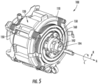
- FIG. 5 provides a perspective view of linear compressor 100 with a compressor shell or housing 102 removed for clarity
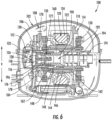
- FIGS. 6 and 7 provide section views of linear compressor when a piston is in an extended and retracted position, respectively.
- linear compressor 100 is used herein only as an exemplary embodiment to facilitate the description of aspects of the present subject matter. Modifications and variations may be made to linear compressor 100 while remaining within the scope of the present subject matter. Indeed, aspects of the present subject matter are applicable to any suitable piston-actuated or reciprocating compressor.
- housing 102 may include a lower portion or lower housing 104 and an upper portion or upper housing 106 which are joined together to form a substantially enclosed cavity 108 for housing various components of linear compressor 100.
- cavity 108 may be a hermetic or air-tight shell that can house working components of linear compressor 100 and may hinder or prevent refrigerant from leaking or escaping from refrigeration system 60.
- linear compressor 100 generally defines an axial direction A, a radial direction R, and a circumferential direction C. It should be appreciated that linear compressor 100 is described and illustrated herein only to describe aspects of the present subject matter. Variations and modifications to linear compressor 100 may be made while remaining within the scope of the present subject matter.
- linear compressor 100 includes a casing 110 that extends between a first end portion 112 and a second end portion 114, e.g., along the axial direction A.
- Casing 110 includes a cylinder 117 that defines a chamber 118.
- Cylinder 117 is positioned at or adjacent first end portion 112 of casing 110.
- Chamber 118 extends longitudinally along the axial direction A.
- linear compressor 100 is operable to increase a pressure of fluid within chamber 118 of linear compressor 100.
- Linear compressor 100 may be used to compress any suitable fluid, such as refrigerant or air.
- linear compressor 100 may be used in a refrigerator appliance, such as refrigerator appliance 10 ( FIG. 1 ) in which linear compressor 100 may be used as compressor 64 ( FIG. 2 ).
- Linear compressor 100 includes a stator 120 of a motor that is mounted or secured to casing 110.
- stator 120 generally includes an outer back iron 122 and a driving coil 124 that extend about the circumferential direction C within casing 110.
- Linear compressor 100 also includes one or more valves that permit refrigerant to enter and exit chamber 118 during operation of linear compressor 100.
- a discharge muffler 126 is positioned at an end of chamber 118 for regulating the flow of refrigerant out of chamber 118, while a suction valve 128 (shown only in FIGS. 6-7 for clarity) regulates flow of refrigerant into chamber 118.
- a piston 130 with a piston head 132 is slidably received within chamber 118 of cylinder 117.
- piston 130 is slidable along the axial direction A.
- piston head 132 compresses refrigerant within chamber 118.
- piston head 132 can slide within chamber 118 towards a bottom dead center position (see, e.g., FIG. 7 ) along the axial direction A, i.e., an expansion stroke of piston head 132.
- linear compressor 100 may include an additional piston head and/or additional chambers at an opposite end of linear compressor 100.
- linear compressor 100 may have multiple piston heads in alternative exemplary embodiments.
- linear compressor 100 also includes a mover 140 which is generally driven by stator 120 for compressing refrigerant.
- mover 140 may include an inner back iron 142 positioned in stator 120 of the motor.
- outer back iron 122 and/or driving coil 124 may extend about inner back iron 142, e.g., along the circumferential direction C.
- Inner back iron 142 also has an outer surface that faces towards outer back iron 122 and/or driving coil 124.
- At least one driving magnet 144 is mounted to inner back iron 142, e.g., at the outer surface of inner back iron 142.
- Driving magnet 144 may face and/or be exposed to driving coil 124.
- driving magnet 144 may be spaced apart from driving coil 124, e.g., along the radial direction R by an air gap.
- the air gap may be defined between opposing surfaces of driving magnet 144 and driving coil 124.
- Driving magnet 144 may also be mounted or fixed to inner back iron 142 such that an outer surface of driving magnet 144 is substantially flush with the outer surface of inner back iron 142.
- driving magnet 144 may be inset within inner back iron 142.
- the magnetic field from driving coil 124 may have to pass through only a single air gap between outer back iron 122 and inner back iron 142 during operation of linear compressor 100, and linear compressor 100 may be more efficient relative to linear compressors with air gaps on both sides of a driving magnet.
- driving coil 124 extends about inner back iron 142, e.g., along the circumferential direction C.
- inner back iron 142 may extend around driving coil 124 along the circumferential direction C.
- Driving coil 124 is operable to move the inner back iron 142 along the axial direction A during operation of driving coil 124.
- a current may be induced within driving coil 124 by a current source (not shown) to generate a magnetic field that engages driving magnet 144 and urges piston 130 to move along the axial direction A in order to compress refrigerant within chamber 118 as described above and will be understood by those skilled in the art.
- driving coil 124 may engage driving magnet 144 in order to move inner back iron 142 and piston head 132 along the axial direction A during operation of driving coil 124.
- driving coil 124 may slide piston 130 between the top dead center position and the bottom dead center position, e.g., by moving inner back iron 142 along the axial direction A, during operation of driving coil 124.
- Linear compressor 100 may include various components for permitting and/or regulating operation of linear compressor 100.
- linear compressor 100 includes a controller (not shown) that is configured for regulating operation of linear compressor 100.
- the controller is in, e.g., operative, communication with the motor, e.g., driving coil 124 of the motor.
- the controller may selectively activate driving coil 124, e.g., by inducing current in driving coil 124, in order to compress refrigerant with piston 130 as described above.
- the controller includes memory and one or more processing devices such as microprocessors, CPUs or the like, such as general or special purpose microprocessors operable to execute programming instructions or micro-control code associated with operation of linear compressor 100.
- the memory can represent random access memory such as DRAM, or read only memory such as ROM or FLASH.
- the processor executes programming instructions stored in the memory.
- the memory can be a separate component from the processor or can be included onboard within the processor.
- the controller may be constructed without using a microprocessor, e.g., using a combination of discrete analog and/or digital logic circuitry (such as switches, amplifiers, integrators, comparators, flip-flops, AND gates, and the like) to perform control functionality instead of relying upon software.
- Inner back iron 142 further includes an outer cylinder 146 and an inner sleeve 148.
- Outer cylinder 146 defines the outer surface of inner back iron 142 and also has an inner surface positioned opposite the outer surface of outer cylinder 146.
- Inner sleeve 148 is positioned on or at inner surface of outer cylinder 146.
- a first interference fit between outer cylinder 146 and inner sleeve 148 may couple or secure outer cylinder 146 and inner sleeve 148 together.
- inner sleeve 148 may be welded, glued, fastened, or connected via any other suitable mechanism or method to outer cylinder 146.
- Outer cylinder 146 may be constructed of or with any suitable material.
- outer cylinder 146 may be constructed of or with a plurality of (e.g., ferromagnetic) laminations. The laminations are distributed along the circumferential direction C in order to form outer cylinder 146 and are mounted to one another or secured together, e.g., with rings pressed onto ends of the laminations.
- Outer cylinder 146 may define a recess that extends inwardly from the outer surface of outer cylinder 146, e.g., along the radial direction R.
- Driving magnet 144 is positioned in the recess on outer cylinder 146, e.g., such that driving magnet 144 is inset within outer cylinder 146.
- Linear compressor 100 also includes a pair of planar springs 150.
- Each planar spring 150 may be coupled to a respective end of inner back iron 142, e.g., along the axial direction A.
- planar springs 150 support inner back iron 142.
- inner back iron 142 is suspended by planar springs 150 within the stator or the motor of linear compressor 100 such that motion of inner back iron 142 along the radial direction R is hindered or limited while motion along the axial direction A is relatively unimpeded.
- planar springs 150 may be substantially stiffer along the radial direction R than along the axial direction A.
- planar springs 150 can assist with maintaining a uniformity of the air gap between driving magnet 144 and driving coil 124, e.g., along the radial direction R, during operation of the motor and movement of inner back iron 142 on the axial direction A. Planar springs 150 can also assist with hindering side pull forces of the motor from transmitting to piston 130 and being reacted in cylinder 117 as a friction loss.
- a flex mount 160 is mounted to and extends through inner back iron 142.
- flex mount 160 is mounted to inner back iron 142 via inner sleeve 148.
- flex mount 160 may be coupled (e.g., threaded) to inner sleeve 148 at the middle portion of inner sleeve 148 and/or flex mount 160 in order to mount or fix flex mount 160 to inner sleeve 148.
- Flex mount 160 may assist with forming a coupling 162.
- Coupling 162 connects inner back iron 142 and piston 130 such that motion of inner back iron 142, e.g., along the axial direction A, is transferred to piston 130.
- Coupling 162 may be a compliant coupling that is compliant or flexible along the radial direction R.
- coupling 162 may be sufficiently compliant along the radial direction R such that little or no motion of inner back iron 142 along the radial direction R is transferred to piston 130 by coupling 162. In such a manner, side pull forces of the motor are decoupled from piston 130 and/or cylinder 117 and friction between piston 130 and cylinder 117 may be reduced.
- piston head 132 of piston 130 has a piston cylindrical side wall 170.
- Cylindrical side wall 170 may extend along the axial direction A from piston head 132 towards inner back iron 142.
- An outer surface of cylindrical side wall 170 may slide on cylinder 117 at chamber 118 and an inner surface of cylindrical side wall 170 may be positioned opposite the outer surface of cylindrical side wall 170.
- the outer surface of cylindrical side wall 170 may face away from a center of cylindrical side wall 170 along the radial direction R, and the inner surface of cylindrical side wall 170 may face towards the center of cylindrical side wall 170 along the radial direction R.
- Flex mount 160 extends between a first end portion 172 and a second end portion 174, e.g., along the axial direction A.
- the inner surface of cylindrical side wall 170 defines a ball seat 176 proximate first end portion.
- coupling 162 also includes a ball nose 178.
- ball nose 178 is positioned at first end portion 172 of flex mount 160, and ball nose 178 may contact flex mount 160 at first end portion 172 of flex mount 160.
- ball nose 178 may contact piston 130 at ball seat 176 of piston 130.
- ball nose 178 may rest on ball seat 176 of piston 130 such that ball nose 178 is slidable and/or rotatable on ball seat 176 of piston 130.
- ball nose 178 may have a frusto-spherical surface positioned against ball seat 176 of piston 130, and ball seat 176 may be shaped complementary to the frusto-spherical surface of ball nose 178.
- the frusto-spherical surface of ball nose 178 may slide and/or rotate on ball seat 176 of piston 130.
- Relative motion between flex mount 160 and piston 130 at the interface between ball nose 178 and ball seat 176 of piston 130 may provide reduced friction between piston 130 and cylinder 117, e.g., compared to a fixed connection between flex mount 160 and piston 130.
- the frusto-spherical surface of ball nose 178 may slide on ball seat 176 of piston 130 to reduce friction between piston 130 and cylinder 117 relative to a rigid connection between inner back iron 142 and piston 130.
- Flex mount 160 is connected to inner back iron 142 away from first end portion 172 of flex mount 160.
- flex mount 160 may be connected to inner back iron 142 at second end portion 174 of flex mount 160 or between first and second end portions 172, 174 of flex mount 160.
- flex mount 160 is positioned at or within piston 130 at first end portion 172 of flex mount 160, as discussed in greater detail below.
- flex mount 160 includes a tubular wall 190 between inner back iron 142 and piston 130.
- a channel 192 within tubular wall 190 is configured for directing compressible fluid, such as refrigerant or air, though flex mount 160 towards piston head 132 and/or into piston 130.
- Inner back iron 142 may be mounted to flex mount 160 such that inner back iron 142 extends around tubular wall 190, e.g., at the middle portion of flex mount 160 between first and second end portions 172, 174 of flex mount 160.
- Channel 192 may extend between first and second end portions 172, 174 of flex mount 160 within tubular wall 190 such that the compressible fluid is flowable from first end portion 172 of flex mount 160 to second end portion 174 of flex mount 160 through channel 192. In such a manner, compressible fluid may flow through inner back iron 142 within flex mount 160 during operation of linear compressor 100.
- a muffler 194 may be positioned within channel 192 within tubular wall 190, e.g., to reduce the noise of compressible fluid flowing through channel 192.
- Piston head 132 also defines at least one opening 196. Opening 196 of piston head 132 extends, e.g., along the axial direction A, through piston head 132. Thus, the flow of fluid may pass through piston head 132 via opening 196 of piston head 132 into chamber 118 during operation of linear compressor 100. In such a manner, the flow of fluid (that is compressed by piston head 132 within chamber 118) may flow within channel 192 through flex mount 160 and inner back iron 142 to piston 130 during operation of linear compressor 100. As explained above, suction valve 128 ( FIGS. 6-7 ) may be positioned on piston head 132 to regulate the flow of compressible fluid through opening 196 into chamber 118.
- piston head assembly 200 for use with a reciprocating compressor will be described according to exemplary embodiments of the present subject matter.
- piston head assembly 200 may be used within linear compressor 100.
- piston head assembly 200 may be used in place of suction valve 128, piston 130, and/or piston head 132, and may be positioned within cylinder 117 for compressing refrigerant within refrigeration system 60.
- piston head assembly 200 is not limited to use within linear compressor 100, but may instead be used in any other suitable application where a piston is used to compress a fluid, gas, refrigerant, etc. Such applications are contemplated as being within the scope of the present subject matter.
- piston head assembly 200 includes a piston 202 that is generally configured for compressing a gas and a valve 204 that is used for selectively permitting a flow of the gas into a chamber for subsequent compression.
- a cylindrical casing 206 may define a compression chamber 208 within which gas (e.g., identified generally by reference numeral 210) may be compressed.
- gas e.g., identified generally by reference numeral 210
- cylindrical casing 206 may be the same or similar to cylinder 117 and compression chamber 208 may be the same or similar to chamber 118.
- a discharge valve 212 e.g., similar to discharge valve 116) may be positioned at the end of cylindrical casing 206 for selectively discharging compressed refrigerant gas 210.
- piston head assembly 200 generally defines an axial direction A and a radial direction R, e.g., which correspond for example to the same directions as for linear compressor 100.
- piston head assembly 200 may be generally configured for drawing a flow of gas 210 from a gas supply 214 into compression chamber 208 through a suction port 220 which is defined within a compression face 222 of piston 202.
- Piston 202 may define an internal chamber fluidly coupled to gas supply 214.
- negative pressure within compression chamber 208 draws the flow of gas 210 through the internal chamber and suction port 220 into compression chamber 208.
- piston 202 may be moved to an extended position along the axial direction A such that compression face 222 compresses gas 210 within compression chamber 208, which may be discharged through discharge valve 212.
- Valve 204 is generally configured for permitting gas 210 to flow into compression chamber 208 during an intake stroke while preventing gas 210 from exiting compression chamber 208 during a compression stroke.
- valve 204 may be secured to compression face 222 of piston 202 using a mechanical fastener 224.
- mechanical fastener 224 is received within a boss 226 defined on a central axis 228 of piston 202.
- mechanical faster 224 is positioned at a center of piston 202 along the radial direction R.
- valve 204 includes an attachment portion 240 that defines an aperture through which mechanical fastener 224 passes to secure valve 204 to piston 202.
- attachment portion 240 is a small, substantially circular island positioned within a center of valve 204. When valve 204 is attached to piston 202, attachment portion 240 is firmly seated against compression face 222.
- valve 204 includes a support portion 242 that extends away from attachment portion 240 along the radial direction R. More specifically, support portion 242 is positioned opposite of suction port 220 relative to central axis 228 or attachment portion 240.
- Valve 204 further includes a sealing portion 244 that is positioned over suction port 220 when valve 204 is attached to piston 202. As shown, attachment portion 240 is positioned between sealing portion 244 and support portion 242 along the radial direction R.
- valve 204 further includes a connecting portion 246 that mechanically couples support portion 242 to sealing portion 244 and permits sealing portion 244 to move between an open position and a closed position.
- connecting portion 246 includes two connecting arms 250 that extend between support portion 242 and sealing portion 244.
- connecting arms 250 generally are arcuate and follow a contour of the perimeter of compression face 222 such that sealing portion 244 is cantilevered relative to attachment portion 240 and support portion 242.
- sealing portion 244 may lift off suction port 220, e.g., by bending or flexing connecting portion 246 (i.e., connecting arms 250).
- connecting arms 250 may be resilient such that at the bottom of the intake stroke, sealing portion 244 may again be seated against suction port 220.
- piston 202 and valve 204 have unique geometries and configurations that facilitate improved operation of piston head assembly 200 and prolonged life of the valve 204.
- the geometries and configurations described herein reduce bending and fatigue stress on valve 204.
- exemplary geometries will be described, it should be appreciated that these geometries may vary while remaining within the scope of the present subject matter.
- valve 204 defines a valve thickness 260 that is measured along the axial direction A or along central axis 228.
- valve 204 may be formed from a single piece of sheet material (e.g., such as thin sheet metal). As such, valve thickness 260 may be constant over the entire valve 204 (i.e., all portions 240-246 have the same thickness).
- suction port 220 is positioned away from or offset relative to central axis 228 of piston 202 along the radial direction R.
- suction port 220 is arcuate or kidney-shaped, e.g., such that it curves partially around central axis 228.
- suction port 220 extends about an arc length of between about 30° and 150°, between about 60° and 120°, or about 90°.
- sealing portion 244 may be similarly arcuate or kidney-shaped.
- valve 204 defines a void 262 between attachment portion 240 and sealing portion 244.
- void 262 may also be kidney-shaped and may wrap or curve around attachment portion 240.
- connecting arms 250 may have a variable thickness or nonuniform cross-section.
- connecting arms 250 may be wider proximate support portion 242 and may be thinner toward sealing portion 244.
- the variation in the cross-sectional width from the thickest portion to the thinnest portion may define a width ratio of greater than 2 to 1, greater than 3 to 1, greater than 4: 1, or greater.
- void 262 may generally be kidney-shaped with enlarged bulbs at each end.
- valve 204 may also have a non-circular shape, e.g., within a radial plane.
- FIG. 12 illustrates a reference circle 270 (dotted lines) that has a fixed radius to illustrate the non-circularity of valve 204.
- support portion 242 defines a flattened end 272 that is positioned opposite sealing portion 244 along the radial direction R.
- Flattened end 272 may be straight and may extend along an arc length of valve 204.
- flattened end 272 extends about an arc length of between about 10° and 110°, between about 30° and 90°, between about 45° and 75°, or about 60°.
- flattened end 272 may provide for higher stiffness and distributed loading in attachment portion 240, support portion 242, and/or connecting portion 246, e.g., in order to minimize stresses on an inner radius of valve 204.
- this allows the distal part of connecting arms 250 (e.g., proximate sealing portion 244) to be more flexible, while maintaining a uniform inner edge stress during opening of valve 204.
- piston 202 may further define a recessed portion 280 that is defined within compression face 222.
- a valve seat 282 may be raised relative to recessed portion 280 and sealing portion 244 may be configured to create a fluid seal against valve seat 282 in the closed position.
- recessed portion 280 generally provides for a better seal against valve seat 282 as valve 204 moves toward the closed position.
- at least a portion of valve 204 may overlap valve seat 282 and/or a portion of compression face 222.
- a portion of sealed portion 244 hangs over valve seat 282 into and over a recessed portion 280 along the radial direction R.
- valve 204 may overlap valve seat 282 by an average overlap distance 284 measured along the radial direction R.
- average overlap distance 284 may be between about 0.05 and 2 mm, between about 0.1 and 1 mm, between about 0.3 and 0.7 mm, or about 0.5 mm.
Landscapes
- Engineering & Computer Science (AREA)
- General Engineering & Computer Science (AREA)
- Mechanical Engineering (AREA)
- Compressor (AREA)
Abstract
Description
- The present subject matter relates generally to reciprocating compressors, and more particularly, to valves for use in reciprocating compressors.
- Certain refrigerator appliances include sealed systems for cooling chilled chambers of the refrigerator appliance. The sealed systems generally include a compressor that generates compressed refrigerant during operation of the sealed system. The compressed refrigerant flows to an evaporator where heat exchange between the chilled chambers and the refrigerant cools the chilled chambers and food items located therein. Recently, certain refrigerator appliances have included reciprocating compressors, such as linear compressors, for compressing refrigerant. Linear compressors generally include a piston and a driving coil. The driving coil generates a force for sliding the piston forward and backward within a chamber. During motion of the piston within the chamber, the piston compresses refrigerant.
- Reciprocating compressors typically include a one-way valve that permits a flow of gas into a compression chamber as the piston moves into a retracted position during an intake stroke and prevents the gas from escaping the compression chamber as the piston moves into an extended position during a compression stroke. For example, the valve may include a flapper valve mounted to a compression face of the piston. The flapper valve may be thin enough to bend under the force of gas pressure from an intake conduit. Notably, the constant bending of the flapper valve commonly results in extreme bending and fatigue stress that can result in premature degradation and failure of the flapper valve.
- In view of this, the existing reciprocating compressor and valve are necessary to be improved to solve the above-mentioned problem.
- An object of the present invention is to provide a reciprocating compressor and a valve with features for improved gas intake and performance.
- The present invention is directed to a reciprocating compressor defining an axial direction and a radial direction is provided. The reciprocating compressor includes a cylindrical casing defining a compression chamber, a piston positioned within the compression chamber and being movable along the axial direction, the piston defining a suction port for receiving a flow of gas, and a valve positioned over the suction port for selectively permitting the flow of gas through the suction port and into the compression chamber. The valve includes a sealing portion positioned over the suction port, an attachment portion mechanically coupled to a compression face of the piston, a support portion that extends away from the attachment portion along the radial direction such that the attachment portion is positioned between the sealing portion and the support portion, wherein the support portion defines a flattened end opposite the sealing portion along the radial direction such that the valve has a non-circular shape, and a connecting portion that mechanically couples the support portion to the sealing portion and permits the sealing portion to move between an open position and a closed position.
- The present invention is also directed to a valve positioned over a suction port of a piston to selectively permit a flow of gas into a compression chamber is provided. The valve includes a sealing portion positioned over the suction port, an attachment portion mechanically coupled to a compression face of the piston, a support portion that extends away from the attachment portion along a radial direction such that the attachment portion is positioned between the sealing portion and the support portion, wherein the support portion defines a flattened end opposite the sealing portion along the radial direction such that the valve has a non-circular shape, and a connecting portion that mechanically couples the support portion to the sealing portion and permits the sealing portion to move between an open position and a closed position.
-
-
FIG. 1 is a front elevation view of a refrigerator appliance according to an example embodiment of the present subject matter. -
FIG. 2 is schematic view of certain components of the example refrigerator appliance ofFIG. 1 . -
FIG. 3 is a perspective, section view of a linear compressor according to an exemplary embodiment of the present subject matter. -
FIG. 4 is another perspective, section view of the exemplary linear compressor ofFIG. 3 according to an exemplary embodiment of the present subject matter. -
FIG. 5 is a perspective view of a linear compressor with a compressor housing removed for clarity according to an example embodiment of the present subject matter. -
FIG. 6 is a section view of the exemplary linear compressor ofFIG. 3 with a piston in an extended position according to an exemplary embodiment of the present subject matter. -
FIG. 7 is a section view of the exemplary linear compressor ofFIG. 3 with the piston in a retracted position according to an exemplary embodiment of the present subject matter. -
FIG. 8 provides an exploded perspective view of a piston and valve that may be used with the exemplary linear compressor ofFIG. 3 according to an exemplary embodiment of the present subject matter. -
FIG. 9 is a top view of a compression face of the exemplary piston and valve ofFIG. 8 according to an exemplary embodiment of the present subject matter. -
FIG. 10 provides a cross sectional view of the exemplary piston and valve ofFIG. 8 according to an exemplary embodiment of the present subject matter. -
FIG. 11 provides a cross sectional view of a valve seat of the exemplary piston and valve ofFIG. 8 according to an exemplary embodiment of the present subject matter. -
FIG. 12 provides a schematic view of the exemplary valve ofFIG. 8 position over a reference circle according to an exemplary embodiment of the present subject matter. - Reference now will be made in detail to embodiments of the invention, one or more examples of which are illustrated in the drawings.
-
FIG. 1 depicts arefrigerator appliance 10 that incorporates a sealed refrigeration system 60 (FIG. 2 ). It should be appreciated that the term "refrigerator appliance" is used in a generic sense herein to encompass any manner of refrigeration appliance, such as a freezer, refrigerator/freezer combination, and any style or model of conventional refrigerator. In addition, it should be understood that the present subject matter is not limited to use in appliances. Thus, the present subject matter may be used for any other suitable purpose, such as vapor compression within air conditioning units or air compression within air compressors. - In the illustrated example embodiment shown in
FIG. 1 , therefrigerator appliance 10 is depicted as an upright refrigerator having a cabinet orcasing 12 that defines a number of internal chilled storage compartments. In particular,refrigerator appliance 10 includes upper fresh-food compartments 14 havingdoors 16 andlower freezer compartment 18 havingupper drawer 20 andlower drawer 22. Thedrawers freezer compartment 18 on suitable slide mechanisms. -
FIG. 2 is a schematic view of certain components ofrefrigerator appliance 10, including a sealedrefrigeration system 60 ofrefrigerator appliance 10. Amachinery compartment 62 contains components for executing a known vapor compression cycle for cooling air. The components include acompressor 64, acondenser 66, anexpansion device 68, and anevaporator 70 connected in series and charged with a refrigerant. As will be understood by those skilled in the art,refrigeration system 60 may include additional components, e.g., at least one additional evaporator, compressor, expansion device, and/or condenser. As an example,refrigeration system 60 may include two evaporators. - Within
refrigeration system 60, refrigerant flows intocompressor 64, which operates to increase the pressure of the refrigerant. This compression of the refrigerant raises its temperature, which is lowered by passing the refrigerant throughcondenser 66. Withincondenser 66, heat exchange with ambient air takes place so as to cool the refrigerant. Afan 72 is used to pull air acrosscondenser 66, as illustrated by arrows AC, so as to provide forced convection for a more rapid and efficient heat exchange between the refrigerant withincondenser 66 and the ambient air. Thus, as will be understood by those skilled in the art, increasing air flow acrosscondenser 66 can, e.g., increase the efficiency ofcondenser 66 by improving cooling of the refrigerant contained therein. - An expansion device 68 (e.g., a valve, capillary tube, or other restriction device) receives refrigerant from
condenser 66. Fromexpansion device 68, the refrigerant entersevaporator 70. Upon exitingexpansion device 68 and enteringevaporator 70, the refrigerant drops in pressure. Due to the pressure drop and/or phase change of the refrigerant,evaporator 70 is cool relative tocompartments refrigerator appliance 10. As such, cooled air is produced and refrigeratescompartments refrigerator appliance 10. Thus,evaporator 70 is a type of heat exchanger which transfers heat from air passing overevaporator 70 to refrigerant flowing throughevaporator 70. - Collectively, the vapor compression cycle components in a refrigeration circuit, associated fans, and associated compartments are sometimes referred to as a sealed refrigeration system operable to force cold air through
compartments 14, 18 (FIG. 1 ). Therefrigeration system 60 depicted inFIG. 2 is provided by way of example only. Thus, it is within the scope of the present subject matter for other configurations of the refrigeration system to be used as well. Furthermore, it should be appreciated that terms such as "refrigerant," "gas," "fluid," and the like are generally intended to refer to a motive fluid for facilitating the operation ofrefrigeration system 60, and may include, fluid, liquid, gas, or any combination thereof in any state. - Referring now generally to
FIGS. 3 through 7 , alinear compressor 100 will be described according to exemplary embodiments of the present subject matter. Specifically,FIGS. 3 and4 provide perspective, section views oflinear compressor 100,FIG. 5 provides a perspective view oflinear compressor 100 with a compressor shell orhousing 102 removed for clarity, andFIGS. 6 and7 provide section views of linear compressor when a piston is in an extended and retracted position, respectively. It should be appreciated thatlinear compressor 100 is used herein only as an exemplary embodiment to facilitate the description of aspects of the present subject matter. Modifications and variations may be made tolinear compressor 100 while remaining within the scope of the present subject matter. Indeed, aspects of the present subject matter are applicable to any suitable piston-actuated or reciprocating compressor. - As illustrated for example in
FIGS. 3 and4 ,housing 102 may include a lower portion orlower housing 104 and an upper portion orupper housing 106 which are joined together to form a substantiallyenclosed cavity 108 for housing various components oflinear compressor 100. Specifically, for example,cavity 108 may be a hermetic or air-tight shell that can house working components oflinear compressor 100 and may hinder or prevent refrigerant from leaking or escaping fromrefrigeration system 60. In addition,linear compressor 100 generally defines an axial direction A, a radial direction R, and a circumferential direction C. It should be appreciated thatlinear compressor 100 is described and illustrated herein only to describe aspects of the present subject matter. Variations and modifications tolinear compressor 100 may be made while remaining within the scope of the present subject matter. - Referring now generally to
FIGS. 3 through 7 , various parts and working components oflinear compressor 100 will be described according to an exemplary embodiment. As shown,linear compressor 100 includes acasing 110 that extends between afirst end portion 112 and asecond end portion 114, e.g., along the axialdirection A. Casing 110 includes acylinder 117 that defines achamber 118.Cylinder 117 is positioned at or adjacentfirst end portion 112 ofcasing 110.Chamber 118 extends longitudinally along the axial direction A. As discussed in greater detail below,linear compressor 100 is operable to increase a pressure of fluid withinchamber 118 oflinear compressor 100.Linear compressor 100 may be used to compress any suitable fluid, such as refrigerant or air. In particular,linear compressor 100 may be used in a refrigerator appliance, such as refrigerator appliance 10 (FIG. 1 ) in whichlinear compressor 100 may be used as compressor 64 (FIG. 2 ). -
Linear compressor 100 includes astator 120 of a motor that is mounted or secured tocasing 110. For example,stator 120 generally includes anouter back iron 122 and a drivingcoil 124 that extend about the circumferential direction C withincasing 110.Linear compressor 100 also includes one or more valves that permit refrigerant to enter andexit chamber 118 during operation oflinear compressor 100. For example, adischarge muffler 126 is positioned at an end ofchamber 118 for regulating the flow of refrigerant out ofchamber 118, while a suction valve 128 (shown only inFIGS. 6-7 for clarity) regulates flow of refrigerant intochamber 118. - A
piston 130 with apiston head 132 is slidably received withinchamber 118 ofcylinder 117. In particular,piston 130 is slidable along the axial direction A. During sliding ofpiston head 132 withinchamber 118,piston head 132 compresses refrigerant withinchamber 118. As an example, from a top dead center position (see, e.g.,FIG. 6 ),piston head 132 can slide withinchamber 118 towards a bottom dead center position (see, e.g.,FIG. 7 ) along the axial direction A, i.e., an expansion stroke ofpiston head 132. Whenpiston head 132 reaches the bottom dead center position,piston head 132 changes directions and slides inchamber 118 back towards the top dead center position, i.e., a compression stroke ofpiston head 132. It should be understood thatlinear compressor 100 may include an additional piston head and/or additional chambers at an opposite end oflinear compressor 100. Thus,linear compressor 100 may have multiple piston heads in alternative exemplary embodiments. - As illustrated,
linear compressor 100 also includes amover 140 which is generally driven bystator 120 for compressing refrigerant. Specifically, for example,mover 140 may include aninner back iron 142 positioned instator 120 of the motor. In particular,outer back iron 122 and/or drivingcoil 124 may extend aboutinner back iron 142, e.g., along the circumferential direction C. Inner backiron 142 also has an outer surface that faces towardsouter back iron 122 and/or drivingcoil 124. At least onedriving magnet 144 is mounted toinner back iron 142, e.g., at the outer surface ofinner back iron 142. - Driving
magnet 144 may face and/or be exposed to drivingcoil 124. In particular, drivingmagnet 144 may be spaced apart from drivingcoil 124, e.g., along the radial direction R by an air gap. Thus, the air gap may be defined between opposing surfaces of drivingmagnet 144 and drivingcoil 124. Drivingmagnet 144 may also be mounted or fixed toinner back iron 142 such that an outer surface of drivingmagnet 144 is substantially flush with the outer surface ofinner back iron 142. Thus, drivingmagnet 144 may be inset withininner back iron 142. In such a manner, the magnetic field from drivingcoil 124 may have to pass through only a single air gap between outerback iron 122 andinner back iron 142 during operation oflinear compressor 100, andlinear compressor 100 may be more efficient relative to linear compressors with air gaps on both sides of a driving magnet. - As may be seen in
FIG. 3 , drivingcoil 124 extends aboutinner back iron 142, e.g., along the circumferential direction C. In alternative example embodiments,inner back iron 142 may extend around drivingcoil 124 along the circumferential directionC. Driving coil 124 is operable to move theinner back iron 142 along the axial direction A during operation of drivingcoil 124. As an example, a current may be induced within drivingcoil 124 by a current source (not shown) to generate a magnetic field that engages drivingmagnet 144 and urgespiston 130 to move along the axial direction A in order to compress refrigerant withinchamber 118 as described above and will be understood by those skilled in the art. In particular, the magnetic field of drivingcoil 124 may engage drivingmagnet 144 in order to moveinner back iron 142 andpiston head 132 along the axial direction A during operation of drivingcoil 124. Thus, drivingcoil 124 may slidepiston 130 between the top dead center position and the bottom dead center position, e.g., by movinginner back iron 142 along the axial direction A, during operation of drivingcoil 124. -
Linear compressor 100 may include various components for permitting and/or regulating operation oflinear compressor 100. In particular,linear compressor 100 includes a controller (not shown) that is configured for regulating operation oflinear compressor 100. The controller is in, e.g., operative, communication with the motor, e.g., drivingcoil 124 of the motor. Thus, the controller may selectively activate drivingcoil 124, e.g., by inducing current in drivingcoil 124, in order to compress refrigerant withpiston 130 as described above. - The controller includes memory and one or more processing devices such as microprocessors, CPUs or the like, such as general or special purpose microprocessors operable to execute programming instructions or micro-control code associated with operation of
linear compressor 100. The memory can represent random access memory such as DRAM, or read only memory such as ROM or FLASH. The processor executes programming instructions stored in the memory. The memory can be a separate component from the processor or can be included onboard within the processor. Alternatively, the controller may be constructed without using a microprocessor, e.g., using a combination of discrete analog and/or digital logic circuitry (such as switches, amplifiers, integrators, comparators, flip-flops, AND gates, and the like) to perform control functionality instead of relying upon software. - Inner
back iron 142 further includes anouter cylinder 146 and aninner sleeve 148.Outer cylinder 146 defines the outer surface ofinner back iron 142 and also has an inner surface positioned opposite the outer surface ofouter cylinder 146.Inner sleeve 148 is positioned on or at inner surface ofouter cylinder 146. A first interference fit betweenouter cylinder 146 andinner sleeve 148 may couple or secureouter cylinder 146 andinner sleeve 148 together. In alternative exemplary embodiments,inner sleeve 148 may be welded, glued, fastened, or connected via any other suitable mechanism or method toouter cylinder 146. -
Outer cylinder 146 may be constructed of or with any suitable material. For example,outer cylinder 146 may be constructed of or with a plurality of (e.g., ferromagnetic) laminations. The laminations are distributed along the circumferential direction C in order to formouter cylinder 146 and are mounted to one another or secured together, e.g., with rings pressed onto ends of the laminations.Outer cylinder 146 may define a recess that extends inwardly from the outer surface ofouter cylinder 146, e.g., along the radial directionR. Driving magnet 144 is positioned in the recess onouter cylinder 146, e.g., such that drivingmagnet 144 is inset withinouter cylinder 146. -
Linear compressor 100 also includes a pair of planar springs 150. Eachplanar spring 150 may be coupled to a respective end ofinner back iron 142, e.g., along the axial direction A. During operation of drivingcoil 124,planar springs 150 supportinner back iron 142. In particular,inner back iron 142 is suspended byplanar springs 150 within the stator or the motor oflinear compressor 100 such that motion ofinner back iron 142 along the radial direction R is hindered or limited while motion along the axial direction A is relatively unimpeded. Thus,planar springs 150 may be substantially stiffer along the radial direction R than along the axial direction A. In such a manner,planar springs 150 can assist with maintaining a uniformity of the air gap between drivingmagnet 144 and drivingcoil 124, e.g., along the radial direction R, during operation of the motor and movement ofinner back iron 142 on the axial direction A. Planar springs 150 can also assist with hindering side pull forces of the motor from transmitting topiston 130 and being reacted incylinder 117 as a friction loss. - A
flex mount 160 is mounted to and extends throughinner back iron 142. In particular,flex mount 160 is mounted toinner back iron 142 viainner sleeve 148. Thus,flex mount 160 may be coupled (e.g., threaded) toinner sleeve 148 at the middle portion ofinner sleeve 148 and/or flexmount 160 in order to mount or fixflex mount 160 toinner sleeve 148.Flex mount 160 may assist with forming acoupling 162. Coupling 162 connectsinner back iron 142 andpiston 130 such that motion ofinner back iron 142, e.g., along the axial direction A, is transferred topiston 130. - Coupling 162 may be a compliant coupling that is compliant or flexible along the radial direction R. In particular, coupling 162 may be sufficiently compliant along the radial direction R such that little or no motion of
inner back iron 142 along the radial direction R is transferred topiston 130 bycoupling 162. In such a manner, side pull forces of the motor are decoupled frompiston 130 and/orcylinder 117 and friction betweenpiston 130 andcylinder 117 may be reduced. - As may be seen in the figures,
piston head 132 ofpiston 130 has a pistoncylindrical side wall 170.Cylindrical side wall 170 may extend along the axial direction A frompiston head 132 towardsinner back iron 142. An outer surface ofcylindrical side wall 170 may slide oncylinder 117 atchamber 118 and an inner surface ofcylindrical side wall 170 may be positioned opposite the outer surface ofcylindrical side wall 170. Thus, the outer surface ofcylindrical side wall 170 may face away from a center ofcylindrical side wall 170 along the radial direction R, and the inner surface ofcylindrical side wall 170 may face towards the center ofcylindrical side wall 170 along the radial direction R. -
Flex mount 160 extends between afirst end portion 172 and asecond end portion 174, e.g., along the axial direction A. According to an exemplary embodiment, the inner surface ofcylindrical side wall 170 defines aball seat 176 proximate first end portion. In addition, coupling 162 also includes aball nose 178. Specifically, for example,ball nose 178 is positioned atfirst end portion 172 offlex mount 160, andball nose 178 may contactflex mount 160 atfirst end portion 172 offlex mount 160. In addition,ball nose 178 may contactpiston 130 atball seat 176 ofpiston 130. In particular,ball nose 178 may rest onball seat 176 ofpiston 130 such thatball nose 178 is slidable and/or rotatable onball seat 176 ofpiston 130. For example,ball nose 178 may have a frusto-spherical surface positioned againstball seat 176 ofpiston 130, andball seat 176 may be shaped complementary to the frusto-spherical surface ofball nose 178. The frusto-spherical surface ofball nose 178 may slide and/or rotate onball seat 176 ofpiston 130. - Relative motion between
flex mount 160 andpiston 130 at the interface betweenball nose 178 andball seat 176 ofpiston 130 may provide reduced friction betweenpiston 130 andcylinder 117, e.g., compared to a fixed connection betweenflex mount 160 andpiston 130. For example, when an axis on whichpiston 130 slides withincylinder 117 is angled relative to the axis on whichinner back iron 142 reciprocates, the frusto-spherical surface ofball nose 178 may slide onball seat 176 ofpiston 130 to reduce friction betweenpiston 130 andcylinder 117 relative to a rigid connection between innerback iron 142 andpiston 130. -
Flex mount 160 is connected toinner back iron 142 away fromfirst end portion 172 offlex mount 160. For example,flex mount 160 may be connected toinner back iron 142 atsecond end portion 174 offlex mount 160 or between first andsecond end portions flex mount 160. Conversely,flex mount 160 is positioned at or withinpiston 130 atfirst end portion 172 offlex mount 160, as discussed in greater detail below. - In addition,
flex mount 160 includes atubular wall 190 between innerback iron 142 andpiston 130. Achannel 192 withintubular wall 190 is configured for directing compressible fluid, such as refrigerant or air, thoughflex mount 160 towardspiston head 132 and/or intopiston 130. Innerback iron 142 may be mounted to flexmount 160 such thatinner back iron 142 extends aroundtubular wall 190, e.g., at the middle portion offlex mount 160 between first andsecond end portions flex mount 160.Channel 192 may extend between first andsecond end portions flex mount 160 withintubular wall 190 such that the compressible fluid is flowable fromfirst end portion 172 offlex mount 160 tosecond end portion 174 offlex mount 160 throughchannel 192. In such a manner, compressible fluid may flow throughinner back iron 142 withinflex mount 160 during operation oflinear compressor 100. Amuffler 194 may be positioned withinchannel 192 withintubular wall 190, e.g., to reduce the noise of compressible fluid flowing throughchannel 192. -
Piston head 132 also defines at least oneopening 196. Opening 196 ofpiston head 132 extends, e.g., along the axial direction A, throughpiston head 132. Thus, the flow of fluid may pass throughpiston head 132 via opening 196 ofpiston head 132 intochamber 118 during operation oflinear compressor 100. In such a manner, the flow of fluid (that is compressed bypiston head 132 within chamber 118) may flow withinchannel 192 throughflex mount 160 andinner back iron 142 topiston 130 during operation oflinear compressor 100. As explained above, suction valve 128 (FIGS. 6-7 ) may be positioned onpiston head 132 to regulate the flow of compressible fluid throughopening 196 intochamber 118. - Referring now to
FIGS. 8 through 12 , an exemplarypiston head assembly 200 for use with a reciprocating compressor will be described according to exemplary embodiments of the present subject matter. For example, according to an exemplary embodiment,piston head assembly 200 may be used withinlinear compressor 100. In this regard, for example,piston head assembly 200 may be used in place ofsuction valve 128,piston 130, and/orpiston head 132, and may be positioned withincylinder 117 for compressing refrigerant withinrefrigeration system 60. However, it should be appreciated thatpiston head assembly 200 is not limited to use withinlinear compressor 100, but may instead be used in any other suitable application where a piston is used to compress a fluid, gas, refrigerant, etc. Such applications are contemplated as being within the scope of the present subject matter. - In general,
piston head assembly 200 includes apiston 202 that is generally configured for compressing a gas and avalve 204 that is used for selectively permitting a flow of the gas into a chamber for subsequent compression. Specifically, as illustrated schematically inFIG. 8 , acylindrical casing 206 may define acompression chamber 208 within which gas (e.g., identified generally by reference numeral 210) may be compressed. For example, continuing the example from above,cylindrical casing 206 may be the same or similar tocylinder 117 andcompression chamber 208 may be the same or similar tochamber 118. In addition, a discharge valve 212 (e.g., similar to discharge valve 116) may be positioned at the end ofcylindrical casing 206 for selectively discharging compressedrefrigerant gas 210. As illustrated,piston head assembly 200 generally defines an axial direction A and a radial direction R, e.g., which correspond for example to the same directions as forlinear compressor 100. - Referring still to
FIG. 8 ,piston head assembly 200 may be generally configured for drawing a flow ofgas 210 from agas supply 214 intocompression chamber 208 through asuction port 220 which is defined within acompression face 222 ofpiston 202.Piston 202 may define an internal chamber fluidly coupled togas supply 214. In operation, aspiston 202 moves toward a retracted position along the axial direction A, negative pressure withincompression chamber 208 draws the flow ofgas 210 through the internal chamber andsuction port 220 intocompression chamber 208. After thecompression chamber 208 is charged withgas 210,piston 202 may be moved to an extended position along the axial direction A such thatcompression face 222 compressesgas 210 withincompression chamber 208, which may be discharged throughdischarge valve 212. -
Valve 204 is generally configured for permittinggas 210 to flow intocompression chamber 208 during an intake stroke while preventinggas 210 from exitingcompression chamber 208 during a compression stroke. As shown,valve 204 may be secured tocompression face 222 ofpiston 202 using amechanical fastener 224. Specifically, according to the illustrated embodiment,mechanical fastener 224 is received within aboss 226 defined on acentral axis 228 ofpiston 202. In other words, mechanical faster 224 is positioned at a center ofpiston 202 along the radial direction R. Althoughvalve 204 is described herein is being joined topiston 202 with amechanical fastener 224, it should be appreciated that any other suitable method of joiningvalve 204 andpiston 202 may be used while remaining within the scope of the present subject matter. Aspects of the present subject matter are directed to animproved valve 204 which will be described in detail below. - Referring now generally to
FIGS. 8 through 12 ,valve 204 includes anattachment portion 240 that defines an aperture through whichmechanical fastener 224 passes to securevalve 204 topiston 202. In general,attachment portion 240 is a small, substantially circular island positioned within a center ofvalve 204. Whenvalve 204 is attached topiston 202,attachment portion 240 is firmly seated againstcompression face 222. In addition,valve 204 includes asupport portion 242 that extends away fromattachment portion 240 along the radial direction R. More specifically,support portion 242 is positioned opposite ofsuction port 220 relative tocentral axis 228 orattachment portion 240.Valve 204 further includes a sealingportion 244 that is positioned oversuction port 220 whenvalve 204 is attached topiston 202. As shown,attachment portion 240 is positioned between sealingportion 244 andsupport portion 242 along the radial direction R. - As shown in the figures,
valve 204 further includes a connectingportion 246 that mechanically couplessupport portion 242 to sealingportion 244 andpermits sealing portion 244 to move between an open position and a closed position. Specifically, according to the illustrated embodiment, connectingportion 246 includes two connectingarms 250 that extend betweensupport portion 242 and sealingportion 244. Specifically, as illustrated, connectingarms 250 generally are arcuate and follow a contour of the perimeter ofcompression face 222 such that sealingportion 244 is cantilevered relative toattachment portion 240 andsupport portion 242. Thus, during an intake stroke, sealingportion 244 may lift offsuction port 220, e.g., by bending or flexing connecting portion 246 (i.e., connecting arms 250). Notably, connectingarms 250 may be resilient such that at the bottom of the intake stroke, sealingportion 244 may again be seated againstsuction port 220. - Notably,
piston 202 andvalve 204 have unique geometries and configurations that facilitate improved operation ofpiston head assembly 200 and prolonged life of thevalve 204. In this regard, the geometries and configurations described herein reduce bending and fatigue stress onvalve 204. Although exemplary geometries will be described, it should be appreciated that these geometries may vary while remaining within the scope of the present subject matter. - According to the illustrated embodiment,
valve 204 defines avalve thickness 260 that is measured along the axial direction A or alongcentral axis 228. According to exemplary embodiments,valve 204 may be formed from a single piece of sheet material (e.g., such as thin sheet metal). As such,valve thickness 260 may be constant over the entire valve 204 (i.e., all portions 240-246 have the same thickness). According to the illustrated embodiment,suction port 220 is positioned away from or offset relative tocentral axis 228 ofpiston 202 along the radial direction R. In addition,suction port 220 is arcuate or kidney-shaped, e.g., such that it curves partially aroundcentral axis 228. Specifically, according to the illustrated embodiment,suction port 220 extends about an arc length of between about 30° and 150°, between about 60° and 120°, or about 90°. Notably, according to the illustrated embodiment, sealingportion 244 may be similarly arcuate or kidney-shaped. - In order to permit flexing of connecting
portion 246 and to move sealingportion 244 to the open position,valve 204 defines a void 262 betweenattachment portion 240 and sealingportion 244. In general, void 262 may also be kidney-shaped and may wrap or curve aroundattachment portion 240. In addition, connectingarms 250 may have a variable thickness or nonuniform cross-section. In this regard, for example, connectingarms 250 may be widerproximate support portion 242 and may be thinner toward sealingportion 244. According to exemplary embodiments, the variation in the cross-sectional width from the thickest portion to the thinnest portion may define a width ratio of greater than 2 to 1, greater than 3 to 1, greater than 4: 1, or greater. As such, void 262 may generally be kidney-shaped with enlarged bulbs at each end. - As best shown in
FIG. 12 ,valve 204 may also have a non-circular shape, e.g., within a radial plane. In this regard,FIG. 12 illustrates a reference circle 270 (dotted lines) that has a fixed radius to illustrate the non-circularity ofvalve 204. As shown,support portion 242 defines a flattenedend 272 that is positioned opposite sealingportion 244 along the radial direction R. Flattenedend 272 may be straight and may extend along an arc length ofvalve 204. Specifically, according to the illustrated embodiment, flattenedend 272 extends about an arc length of between about 10° and 110°, between about 30° and 90°, between about 45° and 75°, or about 60°. Notably, flattenedend 272 may provide for higher stiffness and distributed loading inattachment portion 240,support portion 242, and/or connectingportion 246, e.g., in order to minimize stresses on an inner radius ofvalve 204. For example, this allows the distal part of connecting arms 250 (e.g., proximate sealing portion 244) to be more flexible, while maintaining a uniform inner edge stress during opening ofvalve 204. - Referring now specifically to
FIGS. 8 and10-11 ,piston 202 may further define a recessedportion 280 that is defined withincompression face 222. Avalve seat 282 may be raised relative to recessedportion 280 and sealingportion 244 may be configured to create a fluid seal againstvalve seat 282 in the closed position. Notably, recessedportion 280 generally provides for a better seal againstvalve seat 282 asvalve 204 moves toward the closed position. In addition, as illustrated, at least a portion ofvalve 204 may overlapvalve seat 282 and/or a portion ofcompression face 222. In this regard, for example, a portion of sealedportion 244 hangs overvalve seat 282 into and over a recessedportion 280 along the radial direction R. Notably, this overhang may help minimize impact stresses ofvalve 204. According to exemplary embodiments,valve 204 may overlapvalve seat 282 by anaverage overlap distance 284 measured along the radial direction R. Specifically, according to exemplary embodiments,average overlap distance 284 may be between about 0.05 and 2 mm, between about 0.1 and 1 mm, between about 0.3 and 0.7 mm, or about 0.5 mm. - A series of the detailed descriptions set forth above is merely specific description of feasible embodiments of the present invention, and is not intended to limit the protection scope of the present invention. Equivalent embodiments or modifications made within the spirit of the present invention shall fall within the protection scope of the present invention.
Claims (10)
- A reciprocating compressor defining an axial direction and a radial direction, the reciprocating compressor comprising:a cylindrical casing defining a compression chamber;a piston positioned within the compression chamber and being movable along the axial direction, the piston defining a suction port for receiving a flow of gas; anda valve positioned over the suction port for selectively permitting the flow of gas through the suction port and into the compression chamber, the valve comprising:a sealing portion positioned over the suction port;an attachment portion mechanically coupled to a compression face of the piston;a support portion that extends away from the attachment portion along the radial direction such that the attachment portion is positioned between the sealing portion and the support portion, wherein the support portion defines a flattened end opposite the sealing portion along the radial direction such that the valve has a non-circular shape; anda connecting portion that mechanically couples the support portion to the sealing portion and permits the sealing portion to move between an open position and a closed position.
- The reciprocating compressor of claim 1, wherein the suction port is positioned away from a central axis of the piston along the radial direction.
- The reciprocating compressor of claim 1, wherein the suction port is kidney-shaped.
- The reciprocating compressor of claim 1, wherein a void is defined within the valve between the attachment portion and the sealing portion.
- The reciprocating compressor of claim 4, wherein the void is kidney-shaped and curves around the attachment portion.
- The reciprocating compressor of claim 1, wherein the connecting portion comprises two connecting arms that extend between the support portion and the sealing portion around a perimeter of the compression face of the piston.
- The reciprocating compressor of claim 6, wherein the each of the two connecting arms have non-uniform cross section.
- The reciprocating compressor of claim 1, wherein the attachment portion is positioned on a central axis of the piston, and wherein a mechanical fastener passes through the attachment portion to mount the valve to the piston.
- The reciprocating compressor of claim 1, wherein the piston comprises:a recessed portion defined within the compression face; anda valve seat that is raised relative to the recessed portion, the sealing portion being configured to create a fluid seal against the valve seat in the closed position.
- A valve positioned over a suction port of a piston to selectively permit a flow of gas into a compression chamber, the valve comprising:a sealing portion positioned over the suction port;an attachment portion mechanically coupled to a compression face of the piston;a support portion that extends away from the attachment portion along a radial direction such that the attachment portion is positioned between the sealing portion and the support portion, wherein the support portion defines a flattened end opposite the sealing portion along the radial direction such that the valve has a non-circular shape; anda connecting portion that mechanically couples the support portion to the sealing portion and permits the sealing portion to move between an open position and a closed position.
Applications Claiming Priority (2)
| Application Number | Priority Date | Filing Date | Title |
|---|---|---|---|
| US17/096,195 US11885325B2 (en) | 2020-11-12 | 2020-11-12 | Valve assembly for a reciprocating compressor |
| PCT/CN2021/129261 WO2022100542A1 (en) | 2020-11-12 | 2021-11-08 | Reciprocating compressor and valve thereof |
Publications (3)
| Publication Number | Publication Date |
|---|---|
| EP4227528A1 true EP4227528A1 (en) | 2023-08-16 |
| EP4227528A4 EP4227528A4 (en) | 2024-05-22 |
| EP4227528B1 EP4227528B1 (en) | 2026-02-25 |
Family
ID=81455237
Family Applications (1)
| Application Number | Title | Priority Date | Filing Date |
|---|---|---|---|
| EP21891067.7A Active EP4227528B1 (en) | 2020-11-12 | 2021-11-08 | Reciprocating compressor and valve thereof |
Country Status (4)
| Country | Link |
|---|---|
| US (1) | US11885325B2 (en) |
| EP (1) | EP4227528B1 (en) |
| CN (1) | CN116457576A (en) |
| WO (1) | WO2022100542A1 (en) |
Family Cites Families (45)
| Publication number | Priority date | Publication date | Assignee | Title |
|---|---|---|---|---|
| AU3615001A (en) | 2000-02-17 | 2001-08-27 | Lg Electronics Inc. | Suction gas valve apparatus of reciprocating compressor |
| KR100360261B1 (en) | 2000-08-10 | 2002-11-09 | 엘지전자 주식회사 | Suction valve for compressor |
| BR0004859A (en) | 2000-10-05 | 2002-05-07 | Brasil Compressores Sa | Piston stroke limiting device in reciprocating compressor |
| TW504546B (en) * | 2000-10-17 | 2002-10-01 | Fisher & Amp Paykel Ltd | A linear compressor |
| KR100404465B1 (en) | 2001-04-16 | 2003-11-05 | 주식회사 엘지이아이 | Suction gas guide system for reciprocating compressor |
| DE60126350T2 (en) | 2001-05-25 | 2007-05-31 | Lg Electronics Inc. | SUCTION VALVE FOR PISTON FLOW COMPRESSORS |
| BR0113484B1 (en) | 2001-06-26 | 2011-08-09 | suction valve coupling frame for reciprocating motion compressor. | |
| KR100438605B1 (en) | 2001-08-17 | 2004-07-02 | 엘지전자 주식회사 | Apparatus for compressing gas in reciprocating compressor |
| KR100446770B1 (en) | 2002-01-03 | 2004-09-01 | 엘지전자 주식회사 | Apparatus for sucking gas in linear compressor |
| US7063520B2 (en) | 2002-05-06 | 2006-06-20 | Lg Electronics Inc. | Suction valve assembly of reciprocating compressor |
| KR100455193B1 (en) * | 2002-05-06 | 2004-11-06 | 엘지전자 주식회사 | Device for reducing noise of reciprocating compressor |
| KR20040017959A (en) | 2002-08-23 | 2004-03-02 | 엘지전자 주식회사 | Valve for reciprocating compressor |
| KR100504855B1 (en) | 2002-09-19 | 2005-08-01 | 엘지전자 주식회사 | Valve for compressor |
| KR100480136B1 (en) | 2003-03-04 | 2005-04-07 | 엘지전자 주식회사 | Apparatus of suction valve for liner compressor |
| CN1548731A (en) * | 2003-05-20 | 2004-11-24 | 乐金电子(天津)电器有限公司 | Dead volume reducing structure for reciprocating shifting compressor |
| CN1548741A (en) * | 2003-05-20 | 2004-11-24 | 乐金电子(天津)电器有限公司 | Valve assembly for compressor |
| NZ526361A (en) | 2003-05-30 | 2006-02-24 | Fisher & Paykel Appliances Ltd | Compressor improvements |
| CN100510406C (en) * | 2003-06-17 | 2009-07-08 | 乐金电子(天津)电器有限公司 | Suction valve fixing apparatus for reciprocating compressor |
| KR100548275B1 (en) * | 2003-08-11 | 2006-02-02 | 엘지전자 주식회사 | Suction guide device of reciprocating compressor |
| CN100383385C (en) * | 2003-10-30 | 2008-04-23 | 乐金电子(天津)电器有限公司 | Valve impact buffer device for reciprocating compressor |
| KR20050056601A (en) | 2003-12-10 | 2005-06-16 | 엘지전자 주식회사 | A reciprocating compressor |
| KR100575829B1 (en) | 2003-12-31 | 2006-05-03 | 엘지전자 주식회사 | Suction Muffler Assembly Structure of Reciprocating Compressor |
| KR100539770B1 (en) | 2004-08-16 | 2006-01-10 | 엘지전자 주식회사 | Refrigerant suction guide structure of reciprocating compressor |
| CN1766336A (en) * | 2004-10-27 | 2006-05-03 | 乐金电子(天津)电器有限公司 | Suction valve assembly of reciprocating compressor |
| WO2006049512A2 (en) | 2004-11-02 | 2006-05-11 | Fisher & Paykel Appliances Limited | Piston rod connection forlinear compressor |
| KR100690656B1 (en) | 2004-12-22 | 2007-03-09 | 엘지전자 주식회사 | Reciprocating compressor |
| KR101189448B1 (en) | 2005-05-06 | 2012-10-09 | 엘지전자 주식회사 | Structure for protecting suction valve demage of reciprocating compressor |
| KR100774485B1 (en) | 2005-08-26 | 2007-11-08 | 엘지전자 주식회사 | compressor |
| EP1785625A3 (en) | 2005-11-10 | 2009-11-25 | LG Electronics Inc. | Linear Compressor |
| JP5073989B2 (en) | 2005-11-14 | 2012-11-14 | エルジー エレクトロニクス インコーポレイティド | Linear compressor |
| KR100677291B1 (en) | 2006-01-04 | 2007-02-02 | 엘지전자 주식회사 | Compressor suction valve structure |
| US20070264140A1 (en) * | 2006-05-09 | 2007-11-15 | Chou Wen S | Air compressor having improved valve device |
| CN101240785A (en) * | 2007-02-05 | 2008-08-13 | 周文三 | Piston body structure improvement of air compressor |
| KR20110097069A (en) | 2010-02-24 | 2011-08-31 | 엘지전자 주식회사 | Piston valve fixing structure of cryogenic freezer |
| PL2420708T3 (en) * | 2010-08-16 | 2013-11-29 | Leinemann Gmbh & Co Kg | Switching valve |
| CN203770066U (en) * | 2013-06-28 | 2014-08-13 | Lg电子株式会社 | Linear compressor |
| US20150226210A1 (en) * | 2014-02-10 | 2015-08-13 | General Electric Company | Linear compressor |
| KR102238345B1 (en) * | 2016-05-03 | 2021-04-09 | 엘지전자 주식회사 | Linear compressor |
| ITUA20164632A1 (en) * | 2016-06-23 | 2017-12-23 | Mgf S R L | ASSEMBLY VALVES FOR ALTERNATIVE VOLUMETRIC COMPRESSOR |
| KR102606142B1 (en) | 2016-12-30 | 2023-11-24 | 엘지전자 주식회사 | Linear compressor |
| KR102605743B1 (en) | 2017-01-10 | 2023-11-24 | 엘지전자 주식회사 | Linear compressor |
| KR20180089984A (en) | 2017-02-02 | 2018-08-10 | 엘지전자 주식회사 | Linear compressor |
| KR102612940B1 (en) * | 2017-02-03 | 2023-12-13 | 엘지전자 주식회사 | Reciprocating compressor |
| US10746164B2 (en) * | 2018-05-10 | 2020-08-18 | Haier Us Appliance Solutions, Inc. | Linear compressor with a coupling |
| US10808646B2 (en) * | 2019-01-09 | 2020-10-20 | Haier Us Appliance Solutions, Inc. | Cooled piston and cylinder for compressors and engines |
-
2020
- 2020-11-12 US US17/096,195 patent/US11885325B2/en active Active
-
2021
- 2021-11-08 WO PCT/CN2021/129261 patent/WO2022100542A1/en not_active Ceased
- 2021-11-08 CN CN202180076119.5A patent/CN116457576A/en active Pending
- 2021-11-08 EP EP21891067.7A patent/EP4227528B1/en active Active
Also Published As
| Publication number | Publication date |
|---|---|
| EP4227528B1 (en) | 2026-02-25 |
| US20220145877A1 (en) | 2022-05-12 |
| EP4227528A4 (en) | 2024-05-22 |
| CN116457576A (en) | 2023-07-18 |
| NZ799788A (en) | 2025-02-28 |
| WO2022100542A1 (en) | 2022-05-19 |
| US11885325B2 (en) | 2024-01-30 |
Similar Documents
| Publication | Publication Date | Title |
|---|---|---|
| US20150226210A1 (en) | Linear compressor | |
| US9562525B2 (en) | Linear compressor | |
| US9739270B2 (en) | Linear compressor | |
| US10465671B2 (en) | Compressor with a discharge muffler | |
| US10066615B2 (en) | Linear compressor with a ball joint coupling | |
| US10746164B2 (en) | Linear compressor with a coupling | |
| US9518572B2 (en) | Linear compressor | |
| US9429150B2 (en) | Linear compressor | |
| EP3967877B1 (en) | Linear compressor having oil splash guard | |
| US9841012B2 (en) | Linear compressor | |
| US9528505B2 (en) | Linear compressor | |
| US10100819B2 (en) | Linear compressor | |
| US9702352B2 (en) | Linear compressor and a spring assembly | |
| AU2021260292A1 (en) | Heat radiation assembly of linear compressor | |
| US10113540B2 (en) | Linear compressor | |
| US9506460B2 (en) | Linear compressor | |
| EP4227528B1 (en) | Reciprocating compressor and valve thereof | |
| US20180051685A1 (en) | Compressor with a discharge valve | |
| CN118541543A (en) | Linear compressor and flat spring assemblies | |
| US20250317018A1 (en) | Motor inner iron assembly for a reciprocating compressor | |
| US20250244060A1 (en) | Linear compressor with a self-aligned coupling | |
| US11378069B2 (en) | Compressor |
Legal Events
| Date | Code | Title | Description |
|---|---|---|---|
| STAA | Information on the status of an ep patent application or granted ep patent |
Free format text: STATUS: THE INTERNATIONAL PUBLICATION HAS BEEN MADE |
|
| PUAI | Public reference made under article 153(3) epc to a published international application that has entered the european phase |
Free format text: ORIGINAL CODE: 0009012 |
|
| STAA | Information on the status of an ep patent application or granted ep patent |
Free format text: STATUS: REQUEST FOR EXAMINATION WAS MADE |
|
| 17P | Request for examination filed |
Effective date: 20230508 |
|
| AK | Designated contracting states |
Kind code of ref document: A1 Designated state(s): AL AT BE BG CH CY CZ DE DK EE ES FI FR GB GR HR HU IE IS IT LI LT LU LV MC MK MT NL NO PL PT RO RS SE SI SK SM TR |
|
| DAV | Request for validation of the european patent (deleted) | ||
| DAX | Request for extension of the european patent (deleted) | ||
| A4 | Supplementary search report drawn up and despatched |
Effective date: 20240422 |
|
| RIC1 | Information provided on ipc code assigned before grant |
Ipc: F04B 39/00 20060101ALI20240416BHEP Ipc: F04B 53/12 20060101ALI20240416BHEP Ipc: F04B 53/10 20060101ALI20240416BHEP Ipc: F04B 39/10 20060101ALI20240416BHEP Ipc: F04B 35/04 20060101AFI20240416BHEP |
|
| GRAP | Despatch of communication of intention to grant a patent |
Free format text: ORIGINAL CODE: EPIDOSNIGR1 |
|
| STAA | Information on the status of an ep patent application or granted ep patent |
Free format text: STATUS: GRANT OF PATENT IS INTENDED |
|
| INTG | Intention to grant announced |
Effective date: 20251105 |
|
| GRAS | Grant fee paid |
Free format text: ORIGINAL CODE: EPIDOSNIGR3 |
|
| GRAA | (expected) grant |
Free format text: ORIGINAL CODE: 0009210 |
|
| STAA | Information on the status of an ep patent application or granted ep patent |
Free format text: STATUS: THE PATENT HAS BEEN GRANTED |
|
| AK | Designated contracting states |
Kind code of ref document: B1 Designated state(s): AL AT BE BG CH CY CZ DE DK EE ES FI FR GB GR HR HU IE IS IT LI LT LU LV MC MK MT NL NO PL PT RO RS SE SI SK SM TR |
|
| REG | Reference to a national code |
Ref country code: CH Ref legal event code: F10 Free format text: ST27 STATUS EVENT CODE: U-0-0-F10-F00 (AS PROVIDED BY THE NATIONAL OFFICE) Effective date: 20260225 Ref country code: GB Ref legal event code: FG4D |
|
| REG | Reference to a national code |
Ref country code: DE Ref legal event code: R096 Ref document number: 602021048924 Country of ref document: DE |
|
| REG | Reference to a national code |
Ref country code: IE Ref legal event code: FG4D |