EP4227207A1 - Tillers for marine drives having yaw adjustment device - Google Patents
Tillers for marine drives having yaw adjustment device Download PDFInfo
- Publication number
- EP4227207A1 EP4227207A1 EP23156071.5A EP23156071A EP4227207A1 EP 4227207 A1 EP4227207 A1 EP 4227207A1 EP 23156071 A EP23156071 A EP 23156071A EP 4227207 A1 EP4227207 A1 EP 4227207A1
- Authority
- EP
- European Patent Office
- Prior art keywords
- yaw
- tiller
- tiller arm
- steering bracket
- lock
- Prior art date
- Legal status (The legal status is an assumption and is not a legal conclusion. Google has not performed a legal analysis and makes no representation as to the accuracy of the status listed.)
- Pending
Links
Images












Classifications
-
- B—PERFORMING OPERATIONS; TRANSPORTING
- B63—SHIPS OR OTHER WATERBORNE VESSELS; RELATED EQUIPMENT
- B63H—MARINE PROPULSION OR STEERING
- B63H20/00—Outboard propulsion units, e.g. outboard motors or Z-drives; Arrangements thereof on vessels
- B63H20/08—Means enabling movement of the position of the propulsion element, e.g. for trim, tilt or steering; Control of trim or tilt
- B63H20/12—Means enabling steering
-
- B—PERFORMING OPERATIONS; TRANSPORTING
- B63—SHIPS OR OTHER WATERBORNE VESSELS; RELATED EQUIPMENT
- B63H—MARINE PROPULSION OR STEERING
- B63H20/00—Outboard propulsion units, e.g. outboard motors or Z-drives; Arrangements thereof on vessels
- B63H20/02—Mounting of propulsion units
- B63H20/06—Mounting of propulsion units on an intermediate support
Definitions
- the present disclosure relates to marine drives and particularly to tillers for marine drives.
- U.S. Patent No. 11,186,352 discloses a tiller system for steering a marine propulsion device.
- the tiller system includes a tiller arm rotatably coupled to the marine propulsion device.
- the tiller arm is rotatable from a down position to an up position through a plurality of lock positions therebetween.
- a toothed member is coupled to one of the tiller arm and the marine propulsion device.
- the toothed member defines a plurality of teeth corresponding to the plurality of lock positions for the tiller arm.
- a pawl is coupled to another of the tiller arm and the marine propulsion device, where the pawl engages with the plurality of teeth to prevent the tiller arm from rotating downwardly through the plurality of lock positions.
- U.S. Patent No. 11,097,826 discloses a tiller for an outboard marine drive including a tiller body that is elongated along a tiller axis between a fixed end connected to an outboard marine drive and a distal end.
- a lanyard switch on the tiller body is configured to prevent operation of the outboard marine drive when a lanyard clip is not attached to the lanyard switch.
- a controller is configured to identify that an operator has provided user input to start the outboard marine drive and that the lanyard clip is not connected to the lanyard switch. The controller then generates a lanyard error alert identifying that the lanyard clip is not connected to the lanyard switch.
- U.S. 10,787,236 discloses a tiller system for steering an outboard motor.
- the tiller system includes a tiller arm that is rotatably coupled to the outboard motor.
- the tiller arm is rotatable from a down position to an up position through a plurality of lock positions therebetween.
- a tilt lock system is coupled between the tiller arm and the outboard motor and is configured to be activated and deactivated. When activated, the tilt lock system prevents the tiller arm from rotating downwardly through each of the plurality of lock positions.
- the tiller arm is further rotatable into an unlock position, whereby rotating the tiller arm into the unlock position automatically deactivates the tilt lock system such that the tiller arm is freely rotatable downwardly through the plurality of lock positions.
- U.S. Patent No. 10,696,367 discloses a tiller for an outboard motor has a throttle grip which is manually rotatable through first and second ranges of motion into and between an idle position in which the outboard motor is controlled at an idle speed, and first and second openthrottle positions, respectively, in which the outboard motor is controlled at an above-idle speed.
- a throttle shaft is coupled to the throttle grip and is configured so that rotation of the throttle grip causes rotation of the throttle shaft, which changes a throttle position of a throttle of the outboard motor.
- a rotation direction switching mechanism is manually position-able into a first position in which rotation of the throttle grip through the first range of motion controls the throttle of the outboard motor and alternately manually position-able into a second position in which rotation of the throttle grip through the second range of motion controls the throttle position.
- U.S. Patent No. 10,246,173 discloses a tiller is for an outboard motor and has a manually operable shift mechanism configured to actuate shift changes in a transmission of the outboard motor amongst a forward gear, reverse gear, and neutral gear.
- the tiller also has a manually operable throttle mechanism configured to position a throttle of an internal combustion engine of the outboard motor into and between the idle position and a wide-open throttle position.
- An interlock mechanism is configured to prevent a shift change in the transmission out of the neutral gear when the throttle is positioned in a non-idle position.
- the interlock mechanism is further configured to permit a shift change into the neutral gear regardless of where the throttle is positioned.
- a tiller is for controlling a marine drive.
- the tiller comprises a tiller arm, a base bracket assembly comprising a yaw bracket configured for fixed attachment to a marine drive and a steering bracket which pivotably couples the tiller arm to the yaw bracket for movement about a yaw axis, and a yaw lock configured to lock the steering bracket and tiller arm in a plurality of yaw positions relative to the yaw axis, wherein unlocking the yaw lock facilitates movement of the tiller arm into a new yaw position of the plurality of yaw positions.
- a hand grip is on an outer end of the tiller arm, the hand grip being rotatable relative to the tiller arm so as to control a speed of the marine drive.
- a shaft in the tiller arm is coupled to the hand grip such that rotation of the hand grip causes rotation of the shaft.
- a grip restraining device configured to restrain rotation of the shaft and thus rotation of the hand grip.
- the grip restraining device is located on a bottom of the tiller arm and is accessible from opposite sides of the tiller arm for ambidextrous operation.
- the tiller arm is coupled to the base bracket assembly such that it is pivotable about a tilt axis relative to the base bracket assembly.
- a tilt mechanism comprises a tilt bracket coupled to one of the base bracket assembly or the tiller arm and a pawl coupled to the other one of the base bracket assembly or tiller arm. The tilt mechanism is movable into an engaged position in which the pawl engages the tilt bracket to retain the tiller arm in a selected one of a range of tilt positions relative to the base bracket assembly, and into a disengaged position in which the pawl is disengaged from the tilt bracket such that the tiller arm is freely pivotable about the tilt axis relative to the base bracket assembly.
- the range of tilt positions comprises a downward tilt position in which the tiller arm is angled downwardly relative to horizontal so as to facilitate carrying of the marine drive via the tiller arm.
- the grip restraining device 106 is specially configured to selectively restrain rotation of a hand grip 220 on the outer end of the tiller arm 104.
- the tiller arm 104 has a tilt mechanism 300 which facilitates tilting of the tiller arm 104 relative to the base bracket assembly 102 into and between a variety of tilt positions, including a straight upwardly extending tilt position and a straight downwardly extending tilt position (see Fig. 15 ) for manual carrying of the marine drive via the tiller arm 104.
- the base bracket assembly 102 includes a yaw bracket 114 and a steering bracket 116.
- the yaw bracket 114 is a rigid member having a body 118 and a base 120 which extends from the body 118 and is configured for fixed mounting to a not-shown steering arm of the marine drive, by for example fasteners extending through holes 122 (see Fig. 6 ) in the end of the base 120.
- the body 118 of the yaw bracket 114 provides a pedestal 124.
- a through-bore 126 ( Fig. 4 ) extends through the center portion of the pedestal 124.
- Three engagement recesses 128 extend into the pedestal 124.
- the engagement recesses 128 and partial recesses 130 together span one-hundred-and-eighty degrees relative to the center of the through-bore 126.
- a washer 132 is seated in an annular cavity 136 extending about the through-bore 126.
- the steering bracket 116 is a rigid member having a body 138 and a pair of upwardly angled arms 140 having opposed lower through-bores 142 through the lower ends of the arms 140 and opposed through-bores 144 through the upper ends of arms 140.
- a fastener 145 extends through the opposed through-bores 144 and through a corresponding through-bore 147 ( Fig. 2 ) in the tiller arm 104 so as to couple the tiller arm 104 to the steering bracket 116 in a way that the tiller arm 104 is tiltable up and down relative to the steering bracket 116, as will be further described herein below.
- a through-bore 146 extends through the body 138.
- a fastener 148 extends through the through-bore 146, through the washer 132 and through the through-bore 126 in the body 118 and into threaded engagement with a threaded bolt cap 151.
- the fastener 148 has a body 150 with a smooth outer surface, which is disposed in the through-bore 146, the washer 132 and the through-bore 126 when the fastener 148 is in its position of use.
- the steering bracket 116 is rotatable in either direction relative to the yaw bracket 114 about the fastener 148.
- the yaw bracket 114 is fixed to the steering arm of the marine drive and the steering bracket 116 is attached to the tiller arm 104.
- the tiller arm 104 and steering bracket 116 are pivotable together about the yaw axis 152 ( Fig. 3 ) defined by the fastener 148 into and between a variety of yaw positions relative to the yaw bracket 114 and marine drive, as will be further described herein below.
- a yaw lock 154 ( Fig. 5 ) is specially configured to lock the tiller arm 104 and steering bracket 116 in a variety of yaw positions relative to the yaw bracket 114 and marine drive, as shown by arrows in Figs. 5 and 6 .
- the yaw lock 154 includes a plunger 156 which resides in a through-bore 158 in the steering bracket 116 which defines an internal cavity and relatively smaller top and bottom openings in the body 138 of the steering bracket 116. Referring to Figs.
- the plunger 156 is an elongated member with a top end 160 which normally protrudes out of the top opening, a bottom end 168 which in a locked position protrudes out of the bottom opening, and a relatively enlarged annular body 170 which is trapped in the cavity because it is too big to pass through top and bottom openings.
- a coiled spring 172 is disposed between the top of the annular body 170 and the inside of the cavity adjacent to the top and normally biases the bottom end 168 of the plunger 156 outwardly relative to the bottom opening into the position shown in Fig. 3 .
- the yaw lock 154 also includes a release lever 180 located on top of the steering bracket 116 such that it is easily manually accessible from above and from the sides of the tiller 100.
- the release lever 180 has a first end which is pivotably coupled to mounting boss 184 protruding up from the top of the steering bracket 116, a second end which can be manually lifted by the operator's finger(s) to pivot the release lever 180 upwardly about the pivot axis defined through the mounting boss 184.
- the top end 160 of the plunger 156 protrudes out of the top opening and is pivotally coupled to the bottom of the middle portion of the release lever 180, between the first end and second end.
- Figs. 5 and 6 show the yaw lock 154 in a locked position wherein the bottom end 168 of the plunger 156 is biased by the spring 172 into the center-most engagement recess 128, which retains the steering bracket 116 in a straight-ahead position relative to the yaw bracket 114 and associated marine drive for straight-ahead steering.
- the user manually pivots the first end of the release lever 180 upwardly relative to the mounting boss 184, which pulls upwardly on the plunger 156 and causes the annular body 170 to compress the coiled spring 172.
- the second end of the plunger 156 is removed from the yaw bracket 114, which frees the steering bracket 116 and tiller arm 104 for pivoting motion about the yaw axis 152 ( Fig. 3 ) relative to the yaw bracket 114 and marine drive.
- the steering bracket 116 is pivotable through at least one-hundred-and-eighty degrees relative to the yaw bracket 114 and lockable in each of the yaw positions designated by the engagement recesses 128, 130.
- the user can release the release lever 180, which permits the spring 172 to bias the second end of the plunger 156 outwardly towards and into engagement with the pedestal 124.
- the spring 172 will bias the bottom end 168 of the plunger 156 into the engagement recess 128, 130.
- unlocking the yaw lock 154 advantageously facilitates movement of the tiller arm 104 into a new yaw position relative to the marine drive.
- the tiller arm 104 and steering bracket 116 are pivotable through one-hundred-and-eighty degrees relative to the yaw bracket 114.
- the yaw lock 154 is advantageously configured such that upon movement of the tiller arm 104 and steering bracket 116 into the new yaw position, the yaw lock 154 automatically locks the tiller arm 104 and steering bracket 116 in the new yaw position via engagement of the spring-loaded plunger 156 with another engagement recess 128, 130 of the plurality of recesses.
- the tiller arm 104 extends from an inner end 200 to an outer end 202 in a longitudinal direction LO, from top 204 to bottom 206 in an axial direction AX which is perpendicular to the longitudinal direction LO, and from a first side 208 to a second side 210 which is opposite the first side 208 in a lateral direction LA which is perpendicular to the longitudinal direction LO and perpendicular to the axial direction AX.
- tiller arm 104 has a chassis 212 which is elongated in the longitudinal direction LO and underlies and supports various components associated with the tiller arm 104.
- a cover 214 is mounted on top of chassis 212 and encloses the various components in an interior of the tiller arm 104.
- a shaft 216 protrudes from the interior via a passage defined between the front of the chassis 212 and cover 214.
- the shaft 216 is rotatable about its own axis and has a front end 218 which is coupled to a hand grip 220.
- the hand grip 220 includes a grip member 222 and a grooved grip cover 224.
- the shaft 216 is coupled to the hand grip 220 such that manually rotating the hand grip 220 relative to the chassis 212 and cover 214 causes rotation of the shaft 216 relative to the chassis 212 and cover 214.
- the shaft 216 has a rear end 226 which includes a shaft extension 228 located within a supporting tray 230.
- a magnetic sensor 252 is mounted to the supporting tray 230 and is configured to sense rotation of the shaft 216 (via the shaft extension 228) and communicate such sensed rotation to a controller for the associated marine drive. Sensing arrangements for sensing rotation of a shaft in a tiller arm are conventional and well known in this art and thus not further herein described. As such, it will be understood that rotation of the hand grip 220 causes rotation of the shaft 216, including shaft extension 228 within the supporting tray 230 and such rotation in turn causes change in the speed of the marine drive.
- the hand grip 220 and shaft 216, including shaft extension 228, are rotatable in opposite directions away from the center position shown and thus is configured for ambidextrous use. That is, the hand grip 220 can be rotated in the direction of arrow 234 to increase the speed of the marine drive and alternately the hand grip 220 can be rotated in the direction of arrow 236 to increase the speed of the marine drive, a detent mechanism 240 provides tactile feedback to the user grasping the hand grip 220 when the hand grip 220 is rotated into the center position shown, which corresponds to neutral position for the marine drive.
- the detent mechanism 240 includes a raised groove 242 on the top of the outer diameter of the shaft extension 228 and a roller pin 244 which is coupled to the supporting tray 230 and which becomes aligned with and pops into the raised groove 242 when the hand grip 220 and shaft 216 are rotated into the center position.
- Seating of the roller pin 244 provides tactile feedback in the form of a click which can be felt by the user grasping the hand grip 220.
- Smoothly contoured surfaces 246 provide ramps on opposite sides of the raised groove 242 leading up to the groove and thus provide a gradually increasing resistance to the user rotating the hand grip 220 towards the center position until the roller pin 244 becomes aligned with and seats in the raised groove 242.
- a coiled torsion spring 248 is disposed on the shaft 216 and has a first end attached to the shaft 216 and an opposite, second end attached to the supporting tray 230.
- the coiled torsion spring 248 can include one of two or more springs having opposite winding.
- the torsion spring 248 rotationally biases the shaft 216 towards the center position shown in Fig. 14 , however the bias force provided by the torsion spring 248 is not great enough to overcome the engagement force between the roller pin 244 and the ramped surfaces 246. Instead, it is necessary to apply manual rotational force on the shaft 216 via the hand grip 220 to bring the raised groove 242 into alignment with the roller pin 244.
- the grip restraining device 106 is specially configured to restrain rotation of the shaft 216 and thus rotation of the hand grip 220. This is useful when the user wants to maintain a certain speed of the marine drive without having to continuously hold the hand grip 220. This is also useful when the user wants to vary the amount of resistance which the hand grip 220 provides to rotational force. Some users prefer a hand grip which is more difficult to rotate. Others prefer a hand grip which is easier to rotate.
- the grip restraining device 106 advantageously allow the user to selectively vary and set the resistance.
- the grip restraining device 106 restrains rotation of the hand grip 220 by frictionally engaging the outer diameter of the shaft extension 228 of the shaft 216.
- the shaft extension 228 is a generally cylindrical member having a groove 250 extending around its outer diameter.
- the groove 250 has flanges 252 which are retained in axial position by supporting surfaces of the supporting tray 230.
- the grip restraining device 106 generally includes a dial 254 which is mounted to a hole 256 in the bottom of middle portion of the chassis 212 of the tiller arm 104.
- a snap ring 257 mounts the upper portion of the dial 254 to the chassis 212 such that the dial 254 is freely rotatable relative to the chassis 212.
- Opposed ramped bottom walls 258 extend from the bottom of the chassis 212 and define a protective recess in which the dial 254 resides.
- Side cutouts 262 are defined in each of the bottom walls 258 and expose the outer diameter of the dial 254 on both first and second sides 208, 210 of the tiller arm 104.
- the grip restraining device 106 further includes a shuttle 260 which is disposed in the dial 254,
- the shuttle 260 has an end 264 which is coupled to the interior of the dial 254 by flats such that rotation of the dial 254 causes rotation of the shuttle 260.
- the shuttle 260 has an opposite narrower end 265 which extends into and is engaged with the inner diameter of a boss 266 protruding downwardly from the supporting tray 230 by a threaded connection.
- the shuttle 260 is coupled to the dial 254 and to the boss 266 in the supporting tray 230 such that rotation of the dial 254 in a first direction causes rotation of the shuttle 260 in the first direction, which causes the shuttle 260 to travel axially upwardly further into the boss 266 and towards the shaft extension 228.
- Rotation of the dial 254 in an opposite, second direction causes rotation of the shuttle 260 in the second direction, which causes the shuttle 260 to travel axially downwardly, outwardly relative to the boss 266, further away from the shaft extension 228.
- the grip restraining device 106 further includes a friction plunger 270 which resides within the boss 266.
- the plunger 270 has an outer friction surface 272 which is curved to match and abut the curved outer diameter of the groove 250 of the shaft extension 228.
- a coiled spring 274 has a first end abutting the interior of the shuttle 260 and a second end abutting the inner surface of the friction plunger 270. The spring 274 tends to bias the friction plunger 270 away from the shuttle 260 and into frictional engagement with the groove 250 of the shaft extension 228.
- rotation of the dial 254 in a first rotational direction causes the shuttle 260 to axially move towards the shaft extension 228, which compresses the spring 274 and increases the force of which the friction plunger 270 frictionally engages with the shaft extension 228.
- Rotation of the dial 254 in the opposite, second rotational direction causes the shuttle 260 to axially move away from the shaft extension 228, which allows the spring 274 to relax and decreases the force of which the friction plunger 270 engages with the shaft extension 228. This decreases the restraining force or resistance to manual rotation of the hand grip 220.
- the grip restraining device 106 is manually operable from either side 108, 110 of the tiller arm 104 and thus is configured for ambidextrous use.
- the hand grip 220 is rotatable relative to the tiller arm 104 through at least one-hundred-and-eighty degrees, including 90 degrees away from the center position in the first rotational direction (for right-handed use of the tiller 100), and 90 degrees away from the center position in the opposite, second direction (for left-handed use of the tiller 100).
- the tiller 100 is pivotable relative to the base bracket assembly 102 via connection between the fastener 145 which extends through a through-bore 147 in the tiller arm 104, through the opposed through-bores 144 in the arms 140.
- the fastener 145 defines a tilt axis 299 about which the tiller arm 104 is pivotable relative to the base bracket assembly 102.
- the tilt mechanism 300 also includes a tilt shaft 320 which extends along a tilt shaft axis 322 and is rotatably supported within the opposed through-bores 142 in the arms 140.
- a pawl 324 is pinned to the middle of the tilt shaft 320, axially between the arms 140.
- the pawl 324 is rotatable along with the tilt shaft 320 about the tilt shaft axis 322 and relative to the base bracket assembly 102.
- the pawl 324 has opposing ratchet surfaces 326 having a series of pointed ratchet protrusions for mating in a meshed engagement with the ratchet recesses 312 on the ratchet wheels 306, as will be further described herein below.
- the pawl 324 also has a locking bar 328 located axially between the ratchet surfaces 326.
- the spring 334 and cam body 336 are located in a bore 337 in the respective arm 140 such that the cam body 336 remains rotatably fixed relative to the arm 140 but can axially travel with respect to the tilt shaft 320.
- the coil spring 334 provides a spring bias force that biases the cam body 336 axially outwardly towards the cam receiver 338 in the tilt lever 330.
- the cam body 336 has axially outwardly facing rounded ridges 340 which are configured to alternately nest in correspondingly contoured surfaces 342 in the cam receiver 338 depending on a rotational position of the tilt lever 330, as will be further described herein below.
- contoured surfaces 342 in the cam receiver 338 provide a first elongated pocket for nesting the rounded ridges 340 of the cam body 336 when the tilt mechanism 300 is in the disengaged position (see Fig. 20 ), and a second elongated pocket for nesting the rounded ridges 340 when the tilt mechanism 300 is in the disengaged position (see Fig. 21 ).
- Upward pivoting of the tiller arm 104 is permitted by the tilt mechanism 300 via spring-biased ratcheting movement of the pawl 324 along the ratchet wheels 306, particularly as the ratchet surfaces 326 on the pawl 324 ratchet along the ratchet recesses 312 of the ratchet wheels 310, respectively, until the tiller arm 104 is brought to a rest position, which permits the spring 334 to rotate the pawl 324 towards the tilt bracket 302, causing meshed engagement between the ratchet surfaces 326 and ratchet recesses 312.
- the spring bias is provided by the axial bias of spring 334, pushing the cam body 336 axially into engagement with the cam receiver 338 such that the rounded ridges 340 tend to remain nested in the pocket corresponding to the locked position.
- the tiller arm 104 is rotated upwardly, the ratchet surfaces 326 move along the ratchet surfaces 326, which causes slight counter-clockwise and clockwise movements of the pawl 324 and tilt shaft 320 about the tilt shaft axis 322. Such movements of the pawl 324 and tilt shaft 320 is facilitated by the counter-acting forces provided by the cam device 332.
- the user manually rotates one or both of the tilt levers 330 with a force that is greater than the cam force provided by the cam device 332. This overcomes the bias of the spring 334 and the nested surfaces of the cam body 336 and cam receiver 338 and rotates the locking bar 328 of the pawl 324 into locking engagement with the recess 316 provided by the upper locking arms 314, effectively locking the tiller arm 104 in place.
Landscapes
- Chemical & Material Sciences (AREA)
- Engineering & Computer Science (AREA)
- Combustion & Propulsion (AREA)
- Mechanical Engineering (AREA)
- Ocean & Marine Engineering (AREA)
- Soil Working Implements (AREA)
Abstract
Description
- The present application claims the benefit of and priority to
U.S. Provisional Patent Application Serial No. 63/310,369, filed February 15, 2022 - The present disclosure relates to marine drives and particularly to tillers for marine drives.
- The following U.S. Patents are incorporated herein by reference in entirety.
-
U.S. Patent No. 11,186,352 -
U.S. Patent No. 11,097,826 -
U.S. 10,787,236 -
U.S. Patent No. 10,696,367 -
U.S. Patent No. 10,246,173 - This Summary is provided to introduce a selection of concepts which are further described herein below in the Detailed Description. This Summary is not intended to identify key or essential features of the claimed subject matter, nor is it intended to be used as an aid in limiting scope of the claimed subject matter.
- In non-limiting examples disclosed herein, a tiller is for controlling a marine drive. The tiller comprises a tiller arm, a base bracket assembly comprising a yaw bracket configured for fixed attachment to a marine drive and a steering bracket which pivotably couples the tiller arm to the yaw bracket for movement about a yaw axis, and a yaw lock configured to lock the steering bracket and tiller arm in a plurality of yaw positions relative to the yaw axis, wherein unlocking the yaw lock facilitates movement of the tiller arm into a new yaw position of the plurality of yaw positions.
- In non-limiting examples disclosed herein, a hand grip is on an outer end of the tiller arm, the hand grip being rotatable relative to the tiller arm so as to control a speed of the marine drive. A shaft in the tiller arm is coupled to the hand grip such that rotation of the hand grip causes rotation of the shaft. A grip restraining device configured to restrain rotation of the shaft and thus rotation of the hand grip. The grip restraining device is located on a bottom of the tiller arm and is accessible from opposite sides of the tiller arm for ambidextrous operation.
- In non-limiting examples disclosed herein, the tiller arm is coupled to the base bracket assembly such that it is pivotable about a tilt axis relative to the base bracket assembly. A tilt mechanism comprises a tilt bracket coupled to one of the base bracket assembly or the tiller arm and a pawl coupled to the other one of the base bracket assembly or tiller arm. The tilt mechanism is movable into an engaged position in which the pawl engages the tilt bracket to retain the tiller arm in a selected one of a range of tilt positions relative to the base bracket assembly, and into a disengaged position in which the pawl is disengaged from the tilt bracket such that the tiller arm is freely pivotable about the tilt axis relative to the base bracket assembly. The range of tilt positions comprises a downward tilt position in which the tiller arm is angled downwardly relative to horizontal so as to facilitate carrying of the marine drive via the tiller arm.
- Embodiments are described with reference to the following drawing figures. The same numbers are used throughout to reference like features and components.
-
Fig. 1 is a perspective view looking down at a tiller according to the present disclosure. -
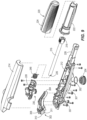
Fig. 2 is an exploded view of the tiller, illustrating a tiller arm including a chassis, a cover and a hand grip, spaced apart from a base bracket assembly comprising a yaw bracket and a steering bracket. -
Fig 3 is a section view of the base bracket assembly. -
Fig. 4 is an exploded view of the base bracket assembly. -
Figs. 5 and 6 are perspective views, partially in phantom, illustrating a yaw lock. -
Fig. 7 is a perspective view looking up at the tiller arm. -
Fig. 8 is a side view of the tiller arm along the grip restraining device. -
Fig. 9 is an exploded view illustrating the tiller arm. -
Fig. 10 is an exploded view illustrating the grip restraining device. -
Fig. 11 is a perspective view, partially in phantom, illustrating the grip restraining device. -
Fig. 12 is a section side view of the grip restraining device. -
Fig. 13 is a perspective view of the grip restraining device. -
Fig. 14 is a sectional end view illustrating the grip restraining device. -
Fig. 15 is a side view illustrating the base bracket assembly and tiller arm, with the tiller arm shown in phantom line in a vertically straight up tilt position and in a vertically straight down tilt position. -
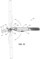
Fig. 16 is a side view illustrating the base bracket assembly and tiller arm, with the tiller arm shown in phantom line in a range of tilt positions. -
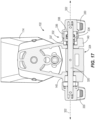
Fig. 17 is a sectional view of the tiller illustrating portions of a tilt mechanism for the tiller, including a tilt shaft, tilt levers, and a cam device. -
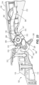
Fig. 18 is a view likeFig. 17 , taken from a different perspective. -
Fig. 19 is a view of one of the tilt levers shown in phantom and the cam device therein. -
Fig. 20 is a side view illustrating the tilt shaft, tilt lever and cam device of the tilt mechanism in an disengaged position. -
Fig. 21 is a view likeFig. 20 illustrating the tilt mechanism in an engaged position. -
Fig. 22 is a side sectional view illustrating the tilt mechanism in the engaged position with the tiller arm in a tilt position that is slightly downward from horizontal. -
Fig. 23 is a side sectional view illustrating the tilt mechanism in the engaged position with the tiller arm in a horizontal tilt position. -
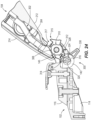
Fig. 24 is a side sectional view illustrating the tiller arm as it is pivoted upwardly towards the uppermost, vertically straight up tilt position and illustrating a tilt bracket of the tilt mechanism as it engages a pawl of the tilt mechanism in such a way that moves the tilt mechanism into the disengaged position by overcoming a cam force provided by the cam device. -
Fig. 25 is a side sectional view illustrating the tilt mechanism in the disengaged position and the tiller arm in the uppermost, vertically straight up tilt position. -
Fig. 26 is a side sectional view illustrating the tilt mechanism in the engaged position and the tiller arm in the uppermost, vertically straight up tilt position. -
Fig. 27 is a side sectional view illustrating the tilt mechanism in the disengaged position and the tiller arm in the lowermost, vertically straight down tilt position. -
Fig. 28 is a side sectional view illustrating the tilt mechanism in the engaged position with the tiller arm in a vertically straight down tilt position. -
Fig. 1 illustrates atiller 100 for controlling a not shown marine drive, such as an outboard motor. In general, thetiller 100 has abase bracket assembly 102 and atiller arm 104 which is coupled to and extends outwardly from thebase bracket assembly 102. Thetiller 100 has several novel attributes which will be further explained herein below. Briefly, thebase bracket assembly 102 is specially configured to facilitate yaw adjustment of thetiller arm 104, in particular into and between a variety of yaw positions relative to the marine drive. In addition, thetiller arm 104 has a novelgrip restraining device 106 which is located on the bottom of the middle portion of thetiller arm 104 and is manually accessible from both sides of thetiller arm 104 for ambidextrous use. Thegrip restraining device 106 is specially configured to selectively restrain rotation of ahand grip 220 on the outer end of thetiller arm 104. In addition, thetiller arm 104 has atilt mechanism 300 which facilitates tilting of thetiller arm 104 relative to thebase bracket assembly 102 into and between a variety of tilt positions, including a straight upwardly extending tilt position and a straight downwardly extending tilt position (seeFig. 15 ) for manual carrying of the marine drive via thetiller arm 104. - Referring to
Figs. 2-6 , thebase bracket assembly 102 includes ayaw bracket 114 and asteering bracket 116. Theyaw bracket 114 is a rigid member having abody 118 and a base 120 which extends from thebody 118 and is configured for fixed mounting to a not-shown steering arm of the marine drive, by for example fasteners extending through holes 122 (seeFig. 6 ) in the end of thebase 120. Thebody 118 of theyaw bracket 114 provides apedestal 124. A through-bore 126 (Fig. 4 ) extends through the center portion of thepedestal 124. Three engagement recesses 128 extend into thepedestal 124. Eachengagement recess 128 has a drain hole 129 (Fig. 3 ) which drains fluid that may accumulate in theengagement recess 128 during normal use. The threeengagement recesses 128 are spaced apart fifteen degrees relative to the through-bore 126. Opposing partial recesses 130 (Fig. 4 ) are formed in the opposing sidewalls of thebody 118 and are located one-hundred-and-eighty degrees apart from each other relative to the center of the through-bore 126. The center-most of the engagement recesses 128 is located ninety degrees apart from each of thepartial recesses 130, respectively, relative to the center of the through-bore 126. The engagement recesses 128 andpartial recesses 130 together span one-hundred-and-eighty degrees relative to the center of the through-bore 126. Awasher 132 is seated in an annular cavity 136 extending about the through-bore 126. - The
steering bracket 116 is a rigid member having abody 138 and a pair of upwardlyangled arms 140 having opposed lower through-bores 142 through the lower ends of thearms 140 and opposed through-bores 144 through the upper ends ofarms 140. Afastener 145 extends through the opposed through-bores 144 and through a corresponding through-bore 147 (Fig. 2 ) in thetiller arm 104 so as to couple thetiller arm 104 to thesteering bracket 116 in a way that thetiller arm 104 is tiltable up and down relative to thesteering bracket 116, as will be further described herein below. - A through-bore 146 (
Fig. 4 ) extends through thebody 138. Afastener 148 extends through the through-bore 146, through thewasher 132 and through the through-bore 126 in thebody 118 and into threaded engagement with a threadedbolt cap 151. Thefastener 148 has abody 150 with a smooth outer surface, which is disposed in the through-bore 146, thewasher 132 and the through-bore 126 when thefastener 148 is in its position of use. As such, thesteering bracket 116 is rotatable in either direction relative to theyaw bracket 114 about thefastener 148. As explained above, theyaw bracket 114 is fixed to the steering arm of the marine drive and thesteering bracket 116 is attached to thetiller arm 104. Thus, thetiller arm 104 andsteering bracket 116 are pivotable together about the yaw axis 152 (Fig. 3 ) defined by thefastener 148 into and between a variety of yaw positions relative to theyaw bracket 114 and marine drive, as will be further described herein below. - A yaw lock 154 (
Fig. 5 ) is specially configured to lock thetiller arm 104 andsteering bracket 116 in a variety of yaw positions relative to theyaw bracket 114 and marine drive, as shown by arrows inFigs. 5 and 6 . Theyaw lock 154 includes aplunger 156 which resides in a through-bore 158 in thesteering bracket 116 which defines an internal cavity and relatively smaller top and bottom openings in thebody 138 of thesteering bracket 116. Referring toFigs. 3 and4 , theplunger 156 is an elongated member with atop end 160 which normally protrudes out of the top opening, abottom end 168 which in a locked position protrudes out of the bottom opening, and a relatively enlargedannular body 170 which is trapped in the cavity because it is too big to pass through top and bottom openings. Acoiled spring 172 is disposed between the top of theannular body 170 and the inside of the cavity adjacent to the top and normally biases thebottom end 168 of theplunger 156 outwardly relative to the bottom opening into the position shown inFig. 3 . - The
yaw lock 154 also includes arelease lever 180 located on top of thesteering bracket 116 such that it is easily manually accessible from above and from the sides of thetiller 100. Therelease lever 180 has a first end which is pivotably coupled to mountingboss 184 protruding up from the top of thesteering bracket 116, a second end which can be manually lifted by the operator's finger(s) to pivot therelease lever 180 upwardly about the pivot axis defined through the mountingboss 184. Thetop end 160 of theplunger 156 protrudes out of the top opening and is pivotally coupled to the bottom of the middle portion of therelease lever 180, between the first end and second end. -
Figs. 5 and 6 show theyaw lock 154 in a locked position wherein thebottom end 168 of theplunger 156 is biased by thespring 172 into thecenter-most engagement recess 128, which retains thesteering bracket 116 in a straight-ahead position relative to theyaw bracket 114 and associated marine drive for straight-ahead steering. As shown by arrows inFigs. 5 and 6 , to change the yaw position of thetiller 100 relative to the marine drive, the user manually pivots the first end of therelease lever 180 upwardly relative to the mountingboss 184, which pulls upwardly on theplunger 156 and causes theannular body 170 to compress thecoiled spring 172. As this occurs, the second end of theplunger 156 is removed from theyaw bracket 114, which frees thesteering bracket 116 andtiller arm 104 for pivoting motion about the yaw axis 152 (Fig. 3 ) relative to theyaw bracket 114 and marine drive. As discussed above, in the illustrated embodiment, thesteering bracket 116 is pivotable through at least one-hundred-and-eighty degrees relative to theyaw bracket 114 and lockable in each of the yaw positions designated by the engagement recesses 128, 130. Particularly, the user can release therelease lever 180, which permits thespring 172 to bias the second end of theplunger 156 outwardly towards and into engagement with thepedestal 124. Once theplunger 156 becomes aligned with a next of the engagement recesses 128, 130, thespring 172 will bias thebottom end 168 of theplunger 156 into theengagement recess - As such, it will be understood that unlocking the
yaw lock 154 advantageously facilitates movement of thetiller arm 104 into a new yaw position relative to the marine drive. In the non-limiting illustrated embodiment, thetiller arm 104 andsteering bracket 116 are pivotable through one-hundred-and-eighty degrees relative to theyaw bracket 114. It will also be understood that theyaw lock 154 is advantageously configured such that upon movement of thetiller arm 104 andsteering bracket 116 into the new yaw position, theyaw lock 154 automatically locks thetiller arm 104 andsteering bracket 116 in the new yaw position via engagement of the spring-loadedplunger 156 with anotherengagement recess - Referring to
Fig. 1 , thetiller arm 104 extends from aninner end 200 to anouter end 202 in a longitudinal direction LO, from top 204 tobottom 206 in an axial direction AX which is perpendicular to the longitudinal direction LO, and from afirst side 208 to asecond side 210 which is opposite thefirst side 208 in a lateral direction LA which is perpendicular to the longitudinal direction LO and perpendicular to the axial direction AX. - Referring to
Fig. 1 ,tiller arm 104 has achassis 212 which is elongated in the longitudinal direction LO and underlies and supports various components associated with thetiller arm 104. Acover 214 is mounted on top ofchassis 212 and encloses the various components in an interior of thetiller arm 104. Referring toFig. 9 , ashaft 216 protrudes from the interior via a passage defined between the front of thechassis 212 andcover 214. Theshaft 216 is rotatable about its own axis and has afront end 218 which is coupled to ahand grip 220. Thehand grip 220 includes agrip member 222 and agrooved grip cover 224. Theshaft 216 is coupled to thehand grip 220 such that manually rotating thehand grip 220 relative to thechassis 212 and cover 214 causes rotation of theshaft 216 relative to thechassis 212 andcover 214. Theshaft 216 has arear end 226 which includes ashaft extension 228 located within a supportingtray 230. Amagnetic sensor 252 is mounted to the supportingtray 230 and is configured to sense rotation of the shaft 216 (via the shaft extension 228) and communicate such sensed rotation to a controller for the associated marine drive. Sensing arrangements for sensing rotation of a shaft in a tiller arm are conventional and well known in this art and thus not further herein described. As such, it will be understood that rotation of thehand grip 220 causes rotation of theshaft 216, includingshaft extension 228 within the supportingtray 230 and such rotation in turn causes change in the speed of the marine drive. - Referring to
Fig. 14 , thehand grip 220 andshaft 216, includingshaft extension 228, are rotatable in opposite directions away from the center position shown and thus is configured for ambidextrous use. That is, thehand grip 220 can be rotated in the direction ofarrow 234 to increase the speed of the marine drive and alternately thehand grip 220 can be rotated in the direction ofarrow 236 to increase the speed of the marine drive, adetent mechanism 240 provides tactile feedback to the user grasping thehand grip 220 when thehand grip 220 is rotated into the center position shown, which corresponds to neutral position for the marine drive. Thedetent mechanism 240 includes a raisedgroove 242 on the top of the outer diameter of theshaft extension 228 and aroller pin 244 which is coupled to the supportingtray 230 and which becomes aligned with and pops into the raisedgroove 242 when thehand grip 220 andshaft 216 are rotated into the center position. Seating of theroller pin 244 provides tactile feedback in the form of a click which can be felt by the user grasping thehand grip 220. Smoothly contouredsurfaces 246 provide ramps on opposite sides of the raisedgroove 242 leading up to the groove and thus provide a gradually increasing resistance to the user rotating thehand grip 220 towards the center position until theroller pin 244 becomes aligned with and seats in the raisedgroove 242. Referring toFigs. 11-13 , in the illustrated example acoiled torsion spring 248 is disposed on theshaft 216 and has a first end attached to theshaft 216 and an opposite, second end attached to the supportingtray 230. In other examples, the coiledtorsion spring 248 can include one of two or more springs having opposite winding. Thetorsion spring 248 rotationally biases theshaft 216 towards the center position shown inFig. 14 , however the bias force provided by thetorsion spring 248 is not great enough to overcome the engagement force between theroller pin 244 and the ramped surfaces 246. Instead, it is necessary to apply manual rotational force on theshaft 216 via thehand grip 220 to bring the raisedgroove 242 into alignment with theroller pin 244. As such, it will be understood that manually grasping and rotating thehand grip 220 away from the center position in eitherdirection hand grip 220 permits the bias of thetorsion spring 248 to rotate theshaft 216 andhand grip 220 back towards the center position until the respective rampedsurface 246 engages theroller pin 244. To fully move thehand grip 220 back to the center position, the user must grasp and rotate thehand grip 220 with a force needed to push the rampedsurface 246 past theroller pin 244 so that theroller pin 244 will pop into place in the raisedgroove 242. - Referring to
Figs. 11-14 , thegrip restraining device 106 is specially configured to restrain rotation of theshaft 216 and thus rotation of thehand grip 220. This is useful when the user wants to maintain a certain speed of the marine drive without having to continuously hold thehand grip 220. This is also useful when the user wants to vary the amount of resistance which thehand grip 220 provides to rotational force. Some users prefer a hand grip which is more difficult to rotate. Others prefer a hand grip which is easier to rotate. Thegrip restraining device 106 advantageously allow the user to selectively vary and set the resistance. - The
grip restraining device 106 restrains rotation of thehand grip 220 by frictionally engaging the outer diameter of theshaft extension 228 of theshaft 216. Theshaft extension 228 is a generally cylindrical member having agroove 250 extending around its outer diameter. Thegroove 250 hasflanges 252 which are retained in axial position by supporting surfaces of the supportingtray 230. Thegrip restraining device 106 generally includes adial 254 which is mounted to ahole 256 in the bottom of middle portion of thechassis 212 of thetiller arm 104. Asnap ring 257 mounts the upper portion of thedial 254 to thechassis 212 such that thedial 254 is freely rotatable relative to thechassis 212. Opposed rampedbottom walls 258 extend from the bottom of thechassis 212 and define a protective recess in which thedial 254 resides.Side cutouts 262 are defined in each of thebottom walls 258 and expose the outer diameter of thedial 254 on both first andsecond sides tiller arm 104. - The
grip restraining device 106 further includes ashuttle 260 which is disposed in thedial 254, Theshuttle 260 has anend 264 which is coupled to the interior of thedial 254 by flats such that rotation of thedial 254 causes rotation of theshuttle 260. Theshuttle 260 has an oppositenarrower end 265 which extends into and is engaged with the inner diameter of aboss 266 protruding downwardly from the supportingtray 230 by a threaded connection. As such, theshuttle 260 is coupled to thedial 254 and to theboss 266 in the supportingtray 230 such that rotation of thedial 254 in a first direction causes rotation of theshuttle 260 in the first direction, which causes theshuttle 260 to travel axially upwardly further into theboss 266 and towards theshaft extension 228. Rotation of thedial 254 in an opposite, second direction causes rotation of theshuttle 260 in the second direction, which causes theshuttle 260 to travel axially downwardly, outwardly relative to theboss 266, further away from theshaft extension 228. - The
grip restraining device 106 further includes afriction plunger 270 which resides within theboss 266. Theplunger 270 has anouter friction surface 272 which is curved to match and abut the curved outer diameter of thegroove 250 of theshaft extension 228. Acoiled spring 274 has a first end abutting the interior of theshuttle 260 and a second end abutting the inner surface of thefriction plunger 270. Thespring 274 tends to bias thefriction plunger 270 away from theshuttle 260 and into frictional engagement with thegroove 250 of theshaft extension 228. - As such, it will be understood that rotation of the
dial 254 in a first rotational direction causes theshuttle 260 to axially move towards theshaft extension 228, which compresses thespring 274 and increases the force of which thefriction plunger 270 frictionally engages with theshaft extension 228. This increases the restraining force or resistance to manual rotation of thehand grip 220. Rotation of thedial 254 in the opposite, second rotational direction causes theshuttle 260 to axially move away from theshaft extension 228, which allows thespring 274 to relax and decreases the force of which thefriction plunger 270 engages with theshaft extension 228. This decreases the restraining force or resistance to manual rotation of thehand grip 220. Advantageously, thegrip restraining device 106 is manually operable from either side 108, 110 of thetiller arm 104 and thus is configured for ambidextrous use. This is particularly advantageous in the illustrated embodiment wherein thehand grip 220 is rotatable relative to thetiller arm 104 through at least one-hundred-and-eighty degrees, including 90 degrees away from the center position in the first rotational direction (for right-handed use of the tiller 100), and 90 degrees away from the center position in the opposite, second direction (for left-handed use of the tiller 100). - As described herein above with reference to
Figs. 1 and2 , thetiller 100 is pivotable relative to thebase bracket assembly 102 via connection between thefastener 145 which extends through a through-bore 147 in thetiller arm 104, through the opposed through-bores 144 in thearms 140. Thefastener 145 defines atilt axis 299 about which thetiller arm 104 is pivotable relative to thebase bracket assembly 102. - Referring to
Figs. 15 and16 , thetiller 100 also has atilt mechanism 300, which advantageously facilitates selective retainment of thetiller arm 104 in any one of a range of userselectable tilt positions relative to thetilt axis 299 on thebase bracket assembly 102.Fig. 15 illustrates via arrows a range of selectable tilt positions of thetiller arm 104 facilitated by thetilt mechanism 300, including in solid line a horizontal tilt position and in phantom lines a vertical straight upward position and in phantom lines a vertical straight downward position, thus spanning a range of selectable positions that extends through 180 degrees relative to thetilt axis 299 on thebase bracket assembly 102.Fig. 16 illustrates thetiller arm 104 in solid lines in the horizontal tilt position and in phantom lines additional upward tilt positions which are in fifteen degree increments relative to each other. As further described herein below, thetilt mechanism 300 advantageously allows the user to move and lock thetiller arm 104 in the illustrated range of tilt positions, including in some examples where thetiller arm 104 is movable at least forty-five degrees downwardly from horizontal, further including in some examples at least seventy-five degrees downwardly from horizontal, and further including in some examples at least ninety degrees downwardly relative to horizontal. As will be further described herein below, thetilt mechanism 300 is engageable to retain thetiller arm 104 in any one of a variety of selected positions. As will be further described herein below, thetilt mechanism 300 is further engageable to lock thetiller arm 104 in the uppermost or lowermost positions. - Referring to
Figs. 9 and22-28 , thetilt mechanism 300 includes atilt bracket 302 which is fastened to theinner end 200 of thetiller arm 104. Thetilt bracket 302 has aninner arm 304 which extends into the interior of thetiller arm 104 defined by thechassis 212 andcover 214. Theinner arm 304 is fixed viafasteners 307 extending through thechassis 212 and into engagement with theinner arm 304. Thetilt bracket 302 extends from theinner end 200 of thetiller arm 104 and has abody 308. A through-bore 311 extending laterally through thebody 308.Ratchet wheels 310 are located on laterally opposite sides of thebody 308, each having a series of two-sided angular ratchet recesses 312 located along the outer radius of the rear side of therespective ratchet wheel 310. Upper and lower pairs of lockingarms body 308 on opposite sides of the series of ratchet recesses 312, respectively. Each of the upper and lower pairs of lockingarms locking recess - Referring to
Figs. 1 and4 , thetilt mechanism 300 also includes atilt shaft 320 which extends along atilt shaft axis 322 and is rotatably supported within the opposed through-bores 142 in thearms 140. Apawl 324 is pinned to the middle of thetilt shaft 320, axially between thearms 140. Thepawl 324 is rotatable along with thetilt shaft 320 about thetilt shaft axis 322 and relative to thebase bracket assembly 102. Thepawl 324 has opposing ratchet surfaces 326 having a series of pointed ratchet protrusions for mating in a meshed engagement with the ratchet recesses 312 on the ratchet wheels 306, as will be further described herein below. Thepawl 324 also has a lockingbar 328 located axially between the ratchet surfaces 326. - Referring to
Fig. 4 andFigs. 17-19 , thetilt mechanism 300 further includes tilt levers 330 fastened to each end of thetilt shaft 320. The tilt levers 330 are manually rotatable, which causes rotation of thetilt shaft 320 andpawl 324 about thetilt shaft axis 322 and with respect to thearms 140. Anovel cam device 332 is located on one end of thetilt shaft 320. Thecam device 332 includes acoil spring 334 disposed on thetilt shaft 320, acam body 336 on thetilt shaft 320 and acam receiver 338 formed on the inside surface of therespective tilt lever 330. Thespring 334 andcam body 336 are located in abore 337 in therespective arm 140 such that thecam body 336 remains rotatably fixed relative to thearm 140 but can axially travel with respect to thetilt shaft 320. Thecoil spring 334 provides a spring bias force that biases thecam body 336 axially outwardly towards thecam receiver 338 in thetilt lever 330. Thecam body 336 has axially outwardly facingrounded ridges 340 which are configured to alternately nest in correspondingly contouredsurfaces 342 in thecam receiver 338 depending on a rotational position of thetilt lever 330, as will be further described herein below. Generally speaking thecontoured surfaces 342 in thecam receiver 338 provide a first elongated pocket for nesting the roundedridges 340 of thecam body 336 when thetilt mechanism 300 is in the disengaged position (seeFig. 20 ), and a second elongated pocket for nesting the roundedridges 340 when thetilt mechanism 300 is in the disengaged position (seeFig. 21 ). As further described herein below, moving thecam device 332 from one of the disengaged position and engaged position to the other of the disengaged position and engaged position requires application of a rotational force on thecam device 332 that is greater than a cam force provided by thespring 334 plus camming engagement between therounded ridges 340 and contouredsurfaces 342 in the nested orientation of thecam body 336 in thecam receiver 338. The rotational force can be applied by manually rotating the tilt levers 330 or by rotating thetiller arm 104 upwardly into the vertical straight upward position shown inFig. 15 . This causes thecontoured surfaces 342 to cammingly engage the roundedridges 340, which in turn causes thecam body 336 to axially travel inwardly away from thecam receiver 338 along thetilt shaft 320 in thebore 337, against the bias of thespring 334, until the contouredsurfaces 342 are removed from the existing pocket in which it resides, which permits further rotation of the tilt levers 330 and corresponding rotation of thetilt shaft 320 andpawl 324 to the other of the disengaged and engaged position, whereafter thespring 334 biases thecam receiver 338 back axially outwardly into engagement with the new pocket. In the illustrated example, thecam device 332 is located on one end of thetilt shaft 320, however in other examples, thetilt mechanism 300 includescam devices 332 on both ends of thetilt shaft 320. Also, in other examples the orientation of thelevers 330 can be flipped 180 degrees to better avoid interference of components. -
Fig. 22 is a side sectional view illustrating thetilt mechanism 300 in an engaged position with thetiller arm 104 in a tilt position that is angled slightly downward from horizontal. Thetilt mechanism 300 is illustrated in the engaged position, wherein thespring 334 is biasing thepawl 324 in the counter-clockwise direction in the side perspective ofFig. 22 , and such that the opposing ratchet surfaces 326 on thepawl 324 are mated with the first few ratchet recesses 312 on the ratchet wheels 306, respectively. As such, thetiller arm 104 is retained in the illustrated tilt position via engagement between thepawl 324 and thebody 308 of thetilt bracket 302. -
Fig. 23 illustrates the tilt mechanism after a user manually pivots thetiller arm 104 upwardly about thetilt axis 299 defined by thefastener 145, counter-clockwise in the side perspective ofFig. 22 . Thetilt mechanism 300 remains in the engaged position and thetiller arm 104 is shown in a generally horizontal position relative to thetilt axis 299 and thebase bracket assembly 102. Upward pivoting of thetiller arm 104 is permitted by thetilt mechanism 300 via spring-biased ratcheting movement of thepawl 324 along the ratchet wheels 306, particularly as the ratchet surfaces 326 on thepawl 324 ratchet along the ratchet recesses 312 of theratchet wheels 310, respectively, until thetiller arm 104 is brought to a rest position, which permits thespring 334 to rotate thepawl 324 towards thetilt bracket 302, causing meshed engagement between the ratchet surfaces 326 and ratchetrecesses 312. The spring bias is provided by the axial bias ofspring 334, pushing thecam body 336 axially into engagement with thecam receiver 338 such that the roundedridges 340 tend to remain nested in the pocket corresponding to the locked position. As thetiller arm 104 is rotated upwardly, the ratchet surfaces 326 move along the ratchet surfaces 326, which causes slight counter-clockwise and clockwise movements of thepawl 324 andtilt shaft 320 about thetilt shaft axis 322. Such movements of thepawl 324 andtilt shaft 320 is facilitated by the counter-acting forces provided by thecam device 332. In particular, slight clockwise rotation of thepawl 324 andtilt shaft 320 is facilitated by camming engagement of the roundedridges 340 upwardly along the contouredsurfaces 342 of the respective pocket. Slight clockwise (return) rotation is cause by the bias of thespring 334, pushing thecam body 336 axially towards thecam receiver 338, which causes the roundedridges 340 to cam back down along the contouredsurfaces 342 into a fully nested position. Compared to the downwardly angled position shown inFig. 22 , more of the ratchet surfaces 326 are engaged withratchet recesses 312 on theratchet wheels 310. -
Fig. 24 illustrates thetiller arm 104 as it is manually pivoted further upwardly relative to thetilt axis 299, further counter-clockwise in the side perspective ofFig. 24 . Such upward pivoting of thetiller arm 104 relative to thetilt axis 299 brings the outside edge of the upper lockingarms 314 into engagement with the upper surface of the lockingbar 328 on thepawl 324, as shown. When thetiller arm 104 is further rotated upwardly from the position shown inFig. 24 , with a rotational force that is greater than the above-noted cam force provided by thecam device 332, the outside edge of the upper lockingarms 314 forces thepawl 324 to rotate downwardly, clockwise in the side perspective ofFig. 24 . More specifically, the rotational force applied on thepawl 324 andtilt shaft 320 rotates thecam receiver 338 relative to thecam body 336, which causes the roundedridges 340 of thecam body 336 to travel upwardly along the contouredsurfaces 342 of thecam receiver 338, against the bias of thespring 334, until the roundedridges 340 fully leave the noted pocket corresponding to the engaged position and become aligned with and nested in the noted pocket corresponding to the disengaged position. This simultaneously causes thetilt shaft 320 andtilt levers 330 to also rotate downwardly until thepawl 324 is rotated out of the way of thetilt bracket 302, as shown inFig. 25 . Thus manually pivoting of thetiller arm 104 upwardly into the position shown inFig. 25 automatically frees thetiller arm 104 to be pivoted back downwardly to any angle. - As shown in
Fig. 26 , if the user wants to lock thetiller arm 104 in the vertical upward position, the user manually rotates one or both of the tilt levers 330 with a force that is greater than the cam force provided by thecam device 332. This overcomes the bias of thespring 334 and the nested surfaces of thecam body 336 andcam receiver 338 and rotates the lockingbar 328 of thepawl 324 into locking engagement with therecess 316 provided by the upper lockingarms 314, effectively locking thetiller arm 104 in place. - As shown in
Figs. 27-28 , if the user wants to unlock thetiller arm 104 and move it downwardly, for example to the vertically straight downward position shown, the user manually rotates one or both of the tilt levers 330 with a force that is greater than the noted cam force. This rotates the lockingbar 328 of thepawl 324 downwardly, clockwise in the side view ofFigs. 27-28 . This removes the lockingbar 328 from therecess 316 and frees thetilt bracket 302 from thepawl 324 and permits the user to manually lower thetiller arm 104 about thetilt axis 299 into the vertically straight downward position shown. Thereafter the user can again rotate the tilt levers 330 counter-clockwise, which brings the lockingbar 328 of thepawl 324 into locking engagement with therecess 317 defined by thelower locking arms 315. This effectively locks thetiller arm 104 in place with a robust tilt mechanism which can be made strong enough to permit a user to carry the associated marine drive via thetiller arm 104 in the position shown inFig. 28 . - In the present description, certain terms have been used for brevity, clarity, and understanding. No unnecessary limitations are to be implied therefrom beyond the requirement of the prior art because such terms are used for descriptive purposes only and are intended to be broadly construed. The different apparatuses described herein may be used alone or in combination with other apparatuses. Various equivalents, alternatives and modifications are possible within the scope of the appended claims.
Claims (15)
- A tiller (100) for a marine drive, the tiller (100) comprising:a tiller arm (104),a base bracket assembly (102) comprising a yaw bracket (114) configured for fixed attachment to a marine drive and a steering bracket (116) which pivotably couples the tiller arm (104) to the yaw bracket (114) for movement about a yaw axis (152), anda yaw lock (154) configured to lock the steering bracket (116) and tiller arm (104) in a plurality of yaw positions relative to the yaw axis (152), wherein unlocking the yaw lock (154) facilitates movement of the tiller arm (104) into a new yaw position of the plurality of yaw positions.
- The tiller (100) according to claim 1, wherein the tiller arm (104) and the steering bracket (116) are movable through at least 90 degrees relative to the yaw axis (152), and further wherein the plurality of yaw positions span at least 90 degrees relative to the yaw axis (152), optionally wherein the tiller arm (104) and steering bracket (116) are movable through at least 180 degrees relative to the yaw axis (152), and further wherein the plurality of yaw positions spans at least 180 degrees relative to the yaw axis (152).
- The tiller (100) according to claim 1 or 2, wherein the yaw lock (154) is configured such that upon said movement of the tiller arm (104) and steering bracket (116) into the new yaw position, the yaw lock (154) automatically locks the tiller arm (104) and steering bracket (116) in the new yaw position.
- The tiller (100) according to claim 1, 2 or 3, wherein the yaw lock (154) comprises a spring-loaded plunger (156) which couples the yaw bracket (114) and steering bracket (116) together to lock the tiller arm (104) in the new yaw position.
- The tiller according to claim 4, wherein the spring-loaded plunger (156) is in the steering bracket (116) and configured to engage in a plurality of recesses (128, 130) in the yaw bracket (114) which corresponds to the plurality of yaw positions.
- The tiller (100) according to claim 5, wherein each recess in the plurality of recesses (128, 130) comprises a drain (129).
- The tiller (100) according to claim 5 or 6, wherein the plurality of recesses (128, 130) spans at least 90 degrees, optionally wherein the plurality of recesses (128, 130) spans at least 180 degrees.
- The tiller (100) according to any one of the preceding claims, wherein the yaw lock (154) is manually operable to unlock the tiller arm (104) and steering bracket (116) from each of the plurality of yaw positions.
- The tiller (100) according to any one of the preceding claims, wherein the yaw lock (154) comprises a release lever (180) which is pivotable to unlock the tiller arm (104) and steering bracket (116).
- The tiller (100) according to claim 9, wherein the yaw lock (154) comprises a spring-loaded plunger (156) which automatically locks the steering bracket (116) in the plurality of yaw positions, and wherein the release lever (180) is pivotable against a bias force of the spring-loaded plunger (156) to unlock the steering bracket (116), optionally wherein the spring-loaded plunger (156) is located in a cavity in the steering bracket (116).
- The tiller (100) according to claim 9 or 10, wherein the release lever (180) is located on top of the steering bracket (116), optionally wherein the release lever (180) has a first end which is pivotably coupled to the steering bracket (116), a second end which can be manually lifted by an operator's finger(s) to pivot the release lever (180) upwardly relative to the steering bracket (116), and optionally wherein the spring-loaded plunger (156) comprises a top end (160) which protrudes out of the steering bracket (116) and is pivotally coupled to a middle portion of the release lever (180), between the first end and the second end.
- The tiller (100) according to any one of the preceding claims, wherein the yaw lock (154) is configured to automatically lock the steering bracket (116) and tiller arm (104) in the plurality of yaw positions relative to the yaw axis (152), and wherein manually unlocking the yaw lock (154) facilitates movement of the tiller arm (104) into the new yaw position of the plurality of yaw positions.
- The tiller (100) according to claim 12, wherein the yaw lock (154) comprises a plunger (156) which resides in a through-bore (158) in the steering bracket (116).
- The tiller (100) according to claim 13, wherein the through-bore (158) in the steering bracket (116) comprises an internal cavity and relatively smaller top and bottom openings in the steering bracket (116), and wherein the plunger (156) is an elongated member having a top end (160) which is spring-biased out of the top opening and a bottom end (168) which in a locked position protrudes out of the bottom opening, and a relatively larger body between the top end (160) and bottom end (168), the relatively larger body being trapped in the internal cavity, optionally further comprising a spring (172) providing said spring bias.
- The tiller (100) according to any one of the preceding claims, wherein the tiller arm (104) and steering bracket (116) are movable through at least 90 degrees relative to the yaw axis (152).
Applications Claiming Priority (2)
| Application Number | Priority Date | Filing Date | Title |
|---|---|---|---|
| US202263310369P | 2022-02-15 | 2022-02-15 | |
| US17/880,987 US12391351B2 (en) | 2022-02-15 | 2022-08-04 | Tillers for marine drives having yaw adjustment device |
Publications (1)
| Publication Number | Publication Date |
|---|---|
| EP4227207A1 true EP4227207A1 (en) | 2023-08-16 |
Family
ID=85225295
Family Applications (1)
| Application Number | Title | Priority Date | Filing Date |
|---|---|---|---|
| EP23156071.5A Pending EP4227207A1 (en) | 2022-02-15 | 2023-02-10 | Tillers for marine drives having yaw adjustment device |
Country Status (2)
| Country | Link |
|---|---|
| US (1) | US12391351B2 (en) |
| EP (1) | EP4227207A1 (en) |
Families Citing this family (11)
| Publication number | Priority date | Publication date | Assignee | Title |
|---|---|---|---|---|
| USD917565S1 (en) | 2017-07-13 | 2021-04-27 | Brunswick Corporation | Tiller for outboard motor |
| USD1043754S1 (en) * | 2019-12-18 | 2024-09-24 | Brunswick Corporation | Outboard motor tiller |
| US12403994B2 (en) | 2022-02-15 | 2025-09-02 | Brunswick Corporation | Tillers for marine drives having tilt mechanism |
| US12545387B2 (en) | 2022-02-15 | 2026-02-10 | Brunswick Corporation | Tillers for marine drives having grip restraining device |
| US12391351B2 (en) | 2022-02-15 | 2025-08-19 | Brunswick Corporation | Tillers for marine drives having yaw adjustment device |
| USD1126998S1 (en) * | 2022-02-15 | 2026-05-19 | Brunswick Corporation | Tiller |
| US12528571B1 (en) | 2022-10-06 | 2026-01-20 | Brunswick Corporation | Tillers for marine drives having ambidextrous functionality |
| US12539953B1 (en) | 2022-10-18 | 2026-02-03 | Brunswick Corporation | Configurable shift and throttle mechanism for tiller of marine drive |
| USD1098197S1 (en) | 2023-12-05 | 2025-10-14 | Brunswick Corporation | Tiller |
| US12662227B1 (en) | 2024-01-08 | 2026-06-23 | Brunswick Corporation | Tillers for controlling an operational characteristic of marine drives |
| CN221698983U (en) * | 2024-02-08 | 2024-09-13 | 布伦斯维克公司 | Tiller for steering a marine drive in relation to a vessel and system for propelling a vessel |
Citations (9)
| Publication number | Priority date | Publication date | Assignee | Title |
|---|---|---|---|---|
| US5540606A (en) * | 1995-06-23 | 1996-07-30 | Leslie O. Paull | Adjustable steering apparatus for outboard motors |
| US20070197109A1 (en) * | 2006-02-17 | 2007-08-23 | Yander Benny W | Trolling Motor Steering Positioner |
| US9789945B1 (en) * | 2016-08-15 | 2017-10-17 | Brunswick Corporation | Angularly adjustable tillers for outboard motors |
| US10246173B1 (en) | 2016-09-01 | 2019-04-02 | Brunswick Corporation | Tillers for outboard motors having neutral shift interlock mechanism |
| US10696367B1 (en) | 2019-01-09 | 2020-06-30 | Brunswick Corporation | Tillers for outboard motors having reversible throttle grip direction |
| US10787236B1 (en) | 2018-02-01 | 2020-09-29 | Brunswick Corporation | Tiller tilt lock and automatic release system |
| US11097824B1 (en) * | 2020-02-06 | 2021-08-24 | Brunswick Corporation | Outboard motor having copilot device |
| US11097826B1 (en) | 2019-07-17 | 2021-08-24 | Brunswick Corporation | Tiller for outboard marine drive having lanyard error alert |
| US11186352B1 (en) | 2019-12-26 | 2021-11-30 | Brunswick Corporation | Systems and methods for incorporating tilt locking into tillers |
Family Cites Families (240)
| Publication number | Priority date | Publication date | Assignee | Title |
|---|---|---|---|---|
| US3636911A (en) | 1970-02-16 | 1972-01-25 | Leisure Products Corp | Power driven aquaplane |
| US1854196A (en) | 1929-10-12 | 1932-04-19 | Outboard Motors Corp | Folding outboard motor |
| US2363854A (en) | 1937-12-01 | 1944-11-28 | Square D Co | Push button switch and mounting |
| US3018754A (en) | 1960-09-12 | 1962-01-30 | Mcculloch Corp | Outboard motor |
| US3693576A (en) | 1971-01-06 | 1972-09-26 | James A Driscoll | Outboard motor stabilizer |
| US3865334A (en) | 1973-01-17 | 1975-02-11 | Jr A Logan Wait | Outboard motor stand |
| US3955527A (en) | 1974-07-08 | 1976-05-11 | Outboard Marine Corporation | Marine propulsion trim tab with anti ventilation means |
| US3961595A (en) | 1974-08-29 | 1976-06-08 | Brunswick Corporation | Steering apparatus for small outboard motors |
| CA1045002A (en) | 1974-08-29 | 1978-12-26 | Brunswick Corporation | Throttle and ignition advance linkage for an internal combustion engine |
| USD246853S (en) | 1976-06-23 | 1978-01-03 | Chrysler Corporation | Exhaust outlet housing for outboard motors |
| US4295835A (en) | 1979-10-09 | 1981-10-20 | Brunswick Corporation | High speed outboard drive unit |
| US4318699A (en) | 1979-12-14 | 1982-03-09 | Brunswick Corporation | Trim control |
| US4331431A (en) | 1980-07-21 | 1982-05-25 | Estes Ronald L | Transom saver |
| USD272357S (en) | 1981-09-03 | 1984-01-24 | Outboard Marine Corporation | Combined outboard motor and mounting bracket assembly therefor |
| US4447214A (en) | 1982-02-11 | 1984-05-08 | Outboard Marine Corporation | Anti-ventilation means for marine gear case |
| JPS58145596A (en) | 1982-02-22 | 1983-08-30 | Sanshin Ind Co Ltd | Steering gear for outboard engine |
| US4504778A (en) | 1982-07-15 | 1985-03-12 | Electronic Systems International, Inc. | Self-powered, self-regulated, electronic ac control system |
| USD276811S (en) | 1982-07-22 | 1984-12-18 | The Eska Company | Electric fishing motor |
| US4496326A (en) | 1982-12-20 | 1985-01-29 | Brunswick Corporation | Selectively disengageable, tiller actuated vane steering system |
| JPS59190085A (en) | 1983-04-12 | 1984-10-27 | Sanshin Ind Co Ltd | Outerboard engine operating system |
| JPS6038293A (en) | 1983-08-10 | 1985-02-27 | Honda Motor Co Ltd | Outboard engine |
| JPS6133395A (en) | 1984-07-25 | 1986-02-17 | Sanshin Ind Co Ltd | Steering device for outboard machine |
| US4650429A (en) | 1985-08-09 | 1987-03-17 | Brunswick Corporation | Throttle friction device for outboard motor |
| US4669987A (en) * | 1985-09-12 | 1987-06-02 | Schulte Richard R | Remote steering assembly kit for outboard trolling motors |
| USD295867S (en) | 1985-12-23 | 1988-05-24 | Brunswick Corporation | Combined tiller arm and control panel for an outboard motor |
| US4878468A (en) | 1987-07-24 | 1989-11-07 | Brunswick Corporation | Cowl assembly for an outboard motor |
| US4800854A (en) | 1987-07-24 | 1989-01-31 | Brunswick Corporation | Cowl assembly for an outboard motor |
| US4838820A (en) | 1987-08-26 | 1989-06-13 | Brunswick Corporation | Preassembled throttle cable linkage |
| US4895154A (en) | 1988-02-19 | 1990-01-23 | Staodynamics, Inc. | Electronic stimulating device for enhanced healing of soft tissue wounds |
| US4897061A (en) | 1988-08-04 | 1990-01-30 | Brunswick Corporation | Gearcase exhaust vent for a marine propulsion system |
| US4911665A (en) | 1988-08-04 | 1990-03-27 | Brunswick Corporation | Gearcase exhaust relief for a marine propulsion system |
| JP2810986B2 (en) | 1989-04-20 | 1998-10-15 | 三信工業株式会社 | Lubrication system for 4-cycle outboard motor |
| USD323508S (en) | 1989-09-26 | 1992-01-28 | Nissan Motor Co., Ltd. | Outboard motor |
| JP2905246B2 (en) | 1990-03-06 | 1999-06-14 | 三信工業株式会社 | Outboard motor steering mechanism |
| USD332265S (en) | 1990-11-13 | 1993-01-05 | Honda Giken Kogyo Kabushiki Kaisha | Outboard motor |
| US5180320A (en) | 1991-06-18 | 1993-01-19 | Outboard Marine Corporation | Trim switch for tiller-steered outboard |
| USD341365S (en) | 1991-10-04 | 1993-11-16 | Ford New Holland, Inc. | Tractor cowling |
| USD343625S (en) | 1992-02-18 | 1994-01-25 | Molded Parts Specialists, Inc. | Electric trolling motor control handle |
| US5277634A (en) | 1992-09-15 | 1994-01-11 | Outboard Marine Corporation | Lower unit torpedo configuration |
| USD352723S (en) | 1992-11-16 | 1994-11-22 | Deere & Company | Vehicle front |
| US5340342A (en) | 1993-06-02 | 1994-08-23 | Brunswick Corporation | Universal tiller handle with shift and throttle |
| US5378178A (en) | 1993-06-15 | 1995-01-03 | Outboard Marine Corporation | Tiller arm and steering bracket assembly |
| USD359290S (en) | 1993-08-05 | 1995-06-13 | Sanshin Kosyo Kabushiki Kaisha | Outboard motor |
| JP3431262B2 (en) | 1994-03-07 | 2003-07-28 | ヤマハマリン株式会社 | Outboard motor |
| US5797777A (en) | 1994-06-22 | 1998-08-25 | Sanshin Kogyo Kabushiki Kaisha | Outboard motor control |
| JPH08222065A (en) | 1995-02-13 | 1996-08-30 | Niles Parts Co Ltd | Hazard switch unit structure |
| US5632657A (en) | 1995-04-02 | 1997-05-27 | Brunswick Corporation | Multi-position adjustable trolling motor tiller handle |
| USD380478S (en) | 1995-04-20 | 1997-07-01 | Brunswick Corporation | Multi-position trolling motor head and handle |
| USD373113S (en) | 1995-05-09 | 1996-08-27 | Steelcase Inc. | Switch |
| USD387775S (en) | 1996-01-31 | 1997-12-16 | Yamaha Hatsudoki Kabushiki Kaisha | Outboard motor |
| US5707262A (en) | 1996-04-23 | 1998-01-13 | Huntley; Jeffery W. | Wireless trim control system for boat drive |
| JP3946315B2 (en) | 1997-07-17 | 2007-07-18 | ヤマハマリン株式会社 | Outboard motor |
| JP3957099B2 (en) | 1997-10-01 | 2007-08-08 | ヤマハマリン株式会社 | Steering friction structure of outboard motor |
| US5967866A (en) | 1997-12-02 | 1999-10-19 | Brunswick Corporation | Texture gearcase for a marine propulsion system |
| US6020563A (en) | 1998-08-06 | 2000-02-01 | Grok Industries, Inc. | Multi-function stalk switch |
| USD418519S (en) | 1998-09-29 | 2000-01-04 | Sanshin Kogyo Kabushiki Kaisha | Outboard motor |
| USD428616S (en) | 1998-09-29 | 2000-07-25 | Sanshin Kogyo Kabushiki Kaisha | Outboard motor |
| USD412911S (en) | 1998-09-29 | 1999-08-17 | Sanshin Kogyo Kabushiki Kaisha | Outboard motor |
| USD460459S1 (en) | 1998-09-30 | 2002-07-16 | Johnson Outdoors Inc. | Trolling motor housing |
| US6109986A (en) | 1998-12-10 | 2000-08-29 | Brunswick Corporation | Idle speed control system for a marine propulsion system |
| USD416871S (en) | 1998-12-23 | 1999-11-23 | Carlingswitch, Inc. | Rocker switch actuator and bezel |
| USD466907S1 (en) | 1998-12-24 | 2002-12-10 | Honda Giken Kogyo Kabushiki Kaisha | Outboard motor for boats |
| JP4094151B2 (en) | 1999-01-26 | 2008-06-04 | ヤマハマリン株式会社 | Outboard motor shift control device |
| US6558213B1 (en) | 1999-05-17 | 2003-05-06 | Bombardier Motor Corporation Of America | High performance engine skeg |
| US6264513B1 (en) | 1999-06-17 | 2001-07-24 | Gregory S. Marsh | Wireless marine control system |
| USD421444S (en) | 1999-08-17 | 2000-03-07 | Brunswick Corporation | Outboard motor cowl |
| JP4297398B2 (en) | 1999-11-19 | 2009-07-15 | ヤマハ発動機株式会社 | Outboard motor storage structure |
| USD447123S1 (en) | 1999-11-20 | 2001-08-28 | Ellenberger & Poensgen Gmbh | Faceplate with rocker switch |
| US6264516B1 (en) | 2000-01-19 | 2001-07-24 | Brunswick Corporation | Outboard motor with disconnectable shift selection and throttle control in a tiller handle |
| US6273771B1 (en) | 2000-03-17 | 2001-08-14 | Brunswick Corporation | Control system for a marine vessel |
| USD458274S1 (en) | 2000-05-04 | 2002-06-04 | Bombardier Motor Corporation Of America | Outboard cowling |
| USD462363S1 (en) | 2000-05-04 | 2002-09-03 | Bombardier Motor Corporation Of America | Outboard cowling |
| USD438493S1 (en) | 2000-05-17 | 2001-03-06 | Craig Mulliniks | Trailer hitch protector |
| US6352456B1 (en) | 2000-09-20 | 2002-03-05 | Brunswick Corporation | Marine propulsion apparatus with adjustable tiller handle |
| USD457166S1 (en) | 2000-09-29 | 2002-05-14 | Bombardier Motor Corporation Of America | Outboard motor |
| USD448037S1 (en) | 2000-11-03 | 2001-09-18 | Deere & Company | Outer surface of a hood |
| USD460972S1 (en) | 2000-11-29 | 2002-07-30 | Honda Giken Kogyo Kabushiki Kaisha | Outboard motor cowl |
| USD463449S1 (en) | 2000-11-29 | 2002-09-24 | Honda Giken Kogyo Kabushiki Kaisha | Outboard motor cowl |
| USD463447S1 (en) | 2000-11-29 | 2002-09-24 | Honda Giken Kogyo Kabushiki Kaisha | Outboard motor cowl |
| USD463448S1 (en) | 2000-11-29 | 2002-09-24 | Honda Giken Kogyo Kabushiki Kaisha | Outboard motor |
| USD463800S1 (en) | 2000-11-29 | 2002-10-01 | Honda Giken Kogyo Kabushiki Kaisha | Outboard motor cowl |
| CA2367740C (en) | 2001-01-19 | 2007-06-12 | Honda Giken Kogyo Kabushiki Kaisha | Outboard marine drive including an engine under cover made of plastic material |
| US6494431B1 (en) | 2001-02-06 | 2002-12-17 | Brunswick Corporation | Support bracket for an outboard motor |
| US6863581B2 (en) | 2001-03-27 | 2005-03-08 | Carl E. Anderson | Trolling motor |
| US6406342B1 (en) | 2001-04-23 | 2002-06-18 | Brunswick Corporation | Control handle for a marine tiller |
| USD460465S1 (en) | 2001-05-22 | 2002-07-16 | Murray, Inc. | Hood for a front engine riding mower |
| US6648703B2 (en) | 2001-06-12 | 2003-11-18 | Bombardier Motor Corporation Of America | Convertible outboard motor tiller arm and motor incorporating same |
| US6382122B1 (en) | 2001-06-22 | 2002-05-07 | Brunswick Corporation | Method for initializing a marine vessel control system |
| US20030024456A1 (en) | 2001-08-03 | 2003-02-06 | Johnson Outdoors Inc. | Variable trolling motor steering control |
| JP4244278B2 (en) | 2002-01-29 | 2009-03-25 | 本田技研工業株式会社 | Steering handle device for outboard motor |
| US7210973B2 (en) | 2002-04-11 | 2007-05-01 | Brp Us Inc. | Outboard engine cowling |
| USD528128S1 (en) | 2002-04-26 | 2006-09-12 | Brp Us Inc. | Cowling |
| USD485847S1 (en) | 2002-04-26 | 2004-01-27 | Bombardier Motor Corporation Of America | Element of the cowling |
| USD495716S1 (en) | 2002-04-26 | 2004-09-07 | Bombardier Recreational Products Inc. | Elements of a cowling |
| USD474784S1 (en) | 2002-04-26 | 2003-05-20 | Bombardier Motor Corporation Of America | Cowling |
| US6663450B1 (en) | 2002-06-14 | 2003-12-16 | Brunswick Corporation | Integral cowl latching mechanism for an outboard motor |
| US6669517B1 (en) | 2002-06-14 | 2003-12-30 | Brunswick Corporation | Multiple part cowl structure for an outboard motor |
| USD489380S1 (en) | 2002-06-19 | 2004-05-04 | Honda Giken Kogyo Kabushiki Kaisha | Outboard motor cowl |
| USD486500S1 (en) | 2002-08-06 | 2004-02-10 | Suzuki Motor Corporation | Outboard motor |
| USD474480S1 (en) | 2002-08-20 | 2003-05-13 | Brunswick Corporation | Outboard motor cowl |
| DE10242976B4 (en) | 2002-09-17 | 2006-03-30 | Jungheinrich Ag | Industrial truck with an electrically operated braking device |
| US6715438B1 (en) | 2002-10-15 | 2004-04-06 | Mark X Steering Systems, Llc | Tiller operated power assist marine steering system |
| USD478597S1 (en) | 2002-10-24 | 2003-08-19 | Brunswick Corporation | Outboard motor cowl |
| US6978694B2 (en) | 2002-12-06 | 2005-12-27 | Magneti Marelli Powertrain U.S.A., Inc. | Handlebar throttle controller with hysteresis |
| US6884132B2 (en) | 2002-12-11 | 2005-04-26 | Yamaha Marine Kabushiki Kaisha Co., Ltd. | Outboard motor with handle bar |
| CA2453466C (en) | 2002-12-25 | 2010-08-24 | Honda Motor Co., Ltd. | Outboard motor and tiller handle thereof |
| USD498485S1 (en) | 2003-02-13 | 2004-11-16 | Kubota Corporation | Front portion of an agricultural tractor |
| US6875066B2 (en) | 2003-02-28 | 2005-04-05 | Polymer Technologies, Inc. | Sound insulation for outboard motors |
| USD497370S1 (en) | 2003-03-20 | 2004-10-19 | Kubota Corporation | Hood portion of an agricultural tractor |
| JP4113798B2 (en) | 2003-03-28 | 2008-07-09 | 株式会社東海理化電機製作所 | Two-stage operation switch device and vehicle window drive device |
| USD531639S1 (en) | 2003-10-29 | 2006-11-07 | Suzuki Motor Corporation | Outboard motor |
| USD495345S1 (en) | 2003-12-17 | 2004-08-31 | Deere & Company | Large row crop tractor hood |
| USD500056S1 (en) | 2004-01-08 | 2004-12-21 | Deere & Company | Rear body portion of a work vehicle |
| JP2005319881A (en) | 2004-05-07 | 2005-11-17 | Yamaha Marine Co Ltd | Steering arm for outboard motor |
| JP2005335448A (en) | 2004-05-25 | 2005-12-08 | Yamaha Marine Co Ltd | Steering rod for outboard motor |
| USD531640S1 (en) | 2004-06-02 | 2006-11-07 | Suzuki Motor Corporation | Outboard motor |
| JP2005349943A (en) | 2004-06-10 | 2005-12-22 | Yamaha Marine Co Ltd | Steering rod for outboard motor |
| US7090551B1 (en) | 2004-09-30 | 2006-08-15 | Brunswick Corporation | Outboard motor tiller handle with upward position locking device |
| US7001231B1 (en) | 2004-10-11 | 2006-02-21 | Brunswick Corporation | Dual water injector for primary and idle relief exhaust passages |
| USD527737S1 (en) | 2004-10-22 | 2006-09-05 | Yamaha Hatsudoki Kabushiki Kaisha | Steering handle for outboard motor |
| USD517096S1 (en) | 2004-11-17 | 2006-03-14 | Deere & Company | Rear portion of a skid steer loader |
| JP2006213152A (en) | 2005-02-03 | 2006-08-17 | Yamaha Marine Co Ltd | Outboard motor |
| USD549240S1 (en) | 2005-06-07 | 2007-08-21 | Suzuki Motor Corporation | Outboard motor |
| JP2007055310A (en) | 2005-08-22 | 2007-03-08 | Honda Motor Co Ltd | Outboard motor |
| USD536704S1 (en) | 2006-01-31 | 2007-02-13 | Yamaha Hatsudoki Kabushiki Kaisha | Outboard motor |
| USD537838S1 (en) | 2006-01-31 | 2007-03-06 | Yamaha Hatsudoki Kabushiki Kaisha | Engine cover for outboard motor |
| JP2007283843A (en) | 2006-04-14 | 2007-11-01 | Yamaha Marine Co Ltd | Outboard motor |
| JP4836652B2 (en) | 2006-04-28 | 2011-12-14 | 本田技研工業株式会社 | Outboard motor |
| USD565607S1 (en) | 2006-05-04 | 2008-04-01 | Cnh America Llc | Vehicular sprayer hood |
| USD584317S1 (en) | 2006-07-05 | 2009-01-06 | Suzuki Motor Corporation | Outboard motor |
| US7267592B1 (en) | 2006-07-24 | 2007-09-11 | Brunswick Corporation | Latching system for an outboard motor cowl |
| USD560050S1 (en) | 2006-08-08 | 2008-01-15 | Clark Equipment Company | Rear cover for a utility vehicle |
| USD552130S1 (en) | 2007-01-04 | 2007-10-02 | Torqeedo Gmbh | Outboard motor |
| USD552129S1 (en) | 2007-01-04 | 2007-10-02 | Torqeedo Gmbh | Outboard motor |
| JP5050578B2 (en) | 2007-03-09 | 2012-10-17 | スズキ株式会社 | Outboard motor handle structure |
| USD611063S1 (en) | 2007-04-13 | 2010-03-02 | Suzuki Motor Corporation | Outboard motor |
| USD611062S1 (en) | 2007-04-13 | 2010-03-02 | Suzuki Motor Corporation | Outboard motor |
| WO2008134762A1 (en) | 2007-04-30 | 2008-11-06 | Electro-Yak Llc | Improved electrically powered watercraft |
| USD563907S1 (en) | 2007-04-30 | 2008-03-11 | Hunter Fan Company | Remote |
| US7736207B2 (en) | 2007-07-13 | 2010-06-15 | Brp Us Inc. | Marine outboard engine having a padded section |
| US7677938B2 (en) | 2007-08-31 | 2010-03-16 | Brp Us Inc. | Tiller arm |
| US7704110B2 (en) | 2007-08-31 | 2010-04-27 | Brp Us Inc. | Engine starting system for a marine outboard engine |
| US7895959B1 (en) | 2007-09-26 | 2011-03-01 | Brunswick Corporation | Differential tiller arms for marine vessels |
| USD589981S1 (en) | 2007-11-30 | 2009-04-07 | Yamaha Hatsudoki Kabushiki Kaisha | Upper parts unit for an outboard motor |
| US7976354B2 (en) | 2008-04-17 | 2011-07-12 | Honda Motor Co., Ltd. | Outboard motor |
| USD635586S1 (en) | 2008-05-12 | 2011-04-05 | Suzuki Motor Corporation | Outboard motor |
| UA19255S (en) | 2008-06-25 | 2009-07-27 | ХОНДА МОТОР КО ЛТ | OUTBOARD BOAT MOTOR |
| USD611501S1 (en) | 2008-06-30 | 2010-03-09 | Brp Us Inc. | Tiller for an outboard engine |
| USD611502S1 (en) | 2008-06-30 | 2010-03-09 | Brp Us Inc. | Tiller for an outboard engine |
| US8371885B2 (en) | 2008-12-12 | 2013-02-12 | Honda Motor Co., Ltd | Outboard motor |
| US8930050B2 (en) | 2009-04-29 | 2015-01-06 | Marine Canada Acquisition Inc. | Method and system for increasing or decreasing engine throttle in a marine vessel |
| US8257122B1 (en) | 2009-05-29 | 2012-09-04 | Brunswick Corporation | Trolling motor direction control assembly and throttle handle |
| US8106617B1 (en) | 2009-05-29 | 2012-01-31 | Brunswick Corporation | Motor power-management protection method and circuit |
| USD622295S1 (en) | 2010-01-29 | 2010-08-24 | Briggs & Stratton Corporation | Lawn tractor grill |
| USD629818S1 (en) | 2010-02-08 | 2010-12-28 | Caterpillar Inc | Cowl and grill assembly |
| USD624567S1 (en) | 2010-02-08 | 2010-09-28 | Caterpillar Inc | Portion of a wheel loader |
| USD635154S1 (en) | 2010-02-08 | 2011-03-29 | Caterpillar Inc. | Rear portion of a motor grader |
| JP5604939B2 (en) | 2010-03-31 | 2014-10-15 | スズキ株式会社 | Electric outboard motor |
| US9004964B2 (en) | 2010-09-10 | 2015-04-14 | Joseph W Grez | Activation and deactivation assembly for an electric outboard motor |
| USD660614S1 (en) | 2010-09-21 | 2012-05-29 | Palmeiri Charles J | Outboard motor stand |
| US9073616B1 (en) | 2010-10-29 | 2015-07-07 | Brp Us Inc. | Marine engine cowling |
| USD663321S1 (en) | 2011-01-18 | 2012-07-10 | Suzuki Motor Corporation | Outboard motor |
| USD643440S1 (en) | 2011-03-02 | 2011-08-16 | Brunswick Corporation | Outboard motor |
| USD657400S1 (en) | 2011-04-06 | 2012-04-10 | Bomag Gmbh | Front part and engine hood of a tandem roller |
| USD655320S1 (en) | 2011-04-08 | 2012-03-06 | Hitachi Construction Machinery Co., Ltd. | Engine cover for construction machine |
| USD660323S1 (en) | 2011-04-08 | 2012-05-22 | Hitachi Construction Machinery Co., Ltd. | Engine cover for construction machine |
| US9109616B1 (en) | 2011-06-24 | 2015-08-18 | Manic Nomad Llc | Clamp |
| JP5741259B2 (en) | 2011-07-05 | 2015-07-01 | スズキ株式会社 | Outboard motor |
| USD655308S1 (en) | 2011-07-15 | 2012-03-06 | Torqeedo Gmbh | Outboard motor |
| US8651906B1 (en) | 2011-08-29 | 2014-02-18 | Brunswick Corporation | Outboard motors and apparatuses for intake of air to outboard motors |
| USD714345S1 (en) | 2012-01-09 | 2014-09-30 | Brp Us Inc. | Marine outboard engine |
| US9039469B1 (en) | 2012-01-31 | 2015-05-26 | Brp Us Inc. | Mounting system for a rear steering assembly of a marine outboard engine |
| JP5927980B2 (en) | 2012-02-24 | 2016-06-01 | スズキ株式会社 | Outboard motor |
| US20130280970A1 (en) | 2012-04-11 | 2013-10-24 | Brunswick Corporation | Marine propulsion systems, intake air systems for marine propulsion systems, and marine propulsion systems having exhaust gas relief outlet |
| US9051041B2 (en) | 2012-08-24 | 2015-06-09 | Brunswick Corporation | Marine propulsion systems having exhaust gas relief outlet |
| US9216805B1 (en) | 2012-06-29 | 2015-12-22 | Brunswick Corporation | Cowl mounting system for outboard marine drive |
| JP6056277B2 (en) | 2012-08-30 | 2017-01-11 | スズキ株式会社 | Electric outboard motor operating device |
| USD712931S1 (en) | 2012-10-29 | 2014-09-09 | Suzuki Motor Corporation | Outboard motor |
| US8820701B1 (en) | 2012-11-28 | 2014-09-02 | Brunswick Corporation | Mounts, mounting arrangements, and methods of making mounting arrangements for supporting outboard motors with respect to marine vessels |
| USD706313S1 (en) | 2013-02-27 | 2014-06-03 | Kubota Corporation | Portion of a vehicle for work machine |
| USD708233S1 (en) | 2013-02-28 | 2014-07-01 | Kubota Corporation | Portion of a wheel loader |
| EP2789262B1 (en) | 2013-04-12 | 2018-06-13 | Logicdata Electronic&Software Entwicklungs GmbH | Adjustable seating furniture with hand-switch arrangement and assembly method for an adjustable seating furniture |
| US9180950B1 (en) | 2013-05-31 | 2015-11-10 | Brp Us Inc. | Outboard engine and air intake system |
| USD727969S1 (en) | 2013-06-28 | 2015-04-28 | Suzuki Motor Corporation | Outboard motor |
| USD707729S1 (en) | 2013-11-06 | 2014-06-24 | Cnh Industrial America Llc | Engine hood of an agricultural vehicle |
| USD720370S1 (en) | 2013-11-08 | 2014-12-30 | J.C. Bamford Excavators Limited | Tractor cab |
| USD709918S1 (en) | 2013-12-04 | 2014-07-29 | Len T. Jones, Sr. | Trolling motor protective cowling |
| US9359059B1 (en) | 2013-12-18 | 2016-06-07 | Brunswick Corporation | Outboard marine engines having gearcase struts with flow separators |
| USD740858S1 (en) | 2014-01-10 | 2015-10-13 | Brunswick Corporation | Outboard motor |
| USD742424S1 (en) | 2014-01-10 | 2015-11-03 | J.C. Bamford Excavators Limited | Wheeled loading shovel vehicle |
| USD715333S1 (en) | 2014-02-28 | 2014-10-14 | Cnh Industrial America Llc | Work vehicle hood |
| US9376194B1 (en) | 2014-06-17 | 2016-06-28 | Brunswick Corporation | Idle relief mufflers and outboard motors having idle relief mufflers |
| US9365277B2 (en) | 2014-07-23 | 2016-06-14 | Brp Us Inc. | Battery connection system for an outboard engine |
| USD791189S1 (en) | 2014-12-01 | 2017-07-04 | Brunswick Corporation | Outboard engine housing |
| USD757126S1 (en) | 2015-02-10 | 2016-05-24 | Brunswick Corporation | Engine cover |
| US9481438B1 (en) | 2015-04-01 | 2016-11-01 | Brunswick Corporation | Outboard motor cowl assembly using shape memory alloy to actuate seal and/or latch |
| US9359981B1 (en) | 2015-05-08 | 2016-06-07 | Brunswick Corporation | Outboard motor with sound enhancement device and method for modifying sounds produced by air intake system of an outboard motor |
| US9926064B1 (en) | 2015-05-26 | 2018-03-27 | Brunswick Corporation | Latching apparatuses for cowls on outboard marine engines |
| MX2018001809A (en) | 2015-08-14 | 2018-05-16 | Crown Equip Corp | Steering and traction applications for determining a steering control attribute and a traction control attribute. |
| US9587601B1 (en) | 2015-09-16 | 2017-03-07 | Yamaha Hatsudoki Kabushiki Kaisha | Outboard motor and watercraft |
| US9580947B1 (en) | 2015-09-30 | 2017-02-28 | Brunswick Corporation | Cowls and latching assemblies for cowls on outboard marine propulsion devices |
| US9701383B1 (en) | 2015-11-13 | 2017-07-11 | Brunswick Corporation | Outboard motor and marine propulsion support system |
| US9694892B1 (en) | 2015-12-29 | 2017-07-04 | Brunswick Corporation | System and method for trimming trimmable marine devices with respect to a marine vessel |
| US9828080B1 (en) | 2016-01-11 | 2017-11-28 | Brunswick Corporation | Lockout for remote controls on marine vessels |
| USD832472S1 (en) | 2016-02-11 | 2018-10-30 | Seven Marine, Llc | Lighting system for an outboard motor for boats |
| DE102016004763A1 (en) | 2016-04-20 | 2017-10-26 | Neander Motors Ag | Internal combustion engine for an outboard engine |
| US9868501B1 (en) | 2016-06-15 | 2018-01-16 | Brunswick Corporation | Method and system for controlling propulsion of a marine vessel |
| US9764813B1 (en) | 2016-08-15 | 2017-09-19 | Brunswick Corporation | Tillers, tiller systems and methods for controlling outboard motors with tillers |
| US9783278B1 (en) | 2016-08-15 | 2017-10-10 | Brunswick Corporation | Tiller having removable top cover |
| USD794078S1 (en) | 2016-08-22 | 2017-08-08 | Brunswick Corporation | Tiller grip |
| USD794079S1 (en) | 2016-09-02 | 2017-08-08 | Brunswick Corporation | Tiller having haptic throttle position indication |
| USD816716S1 (en) | 2016-09-02 | 2018-05-01 | Brunswick Corporation | Outboard marine engine cover |
| US10597118B2 (en) | 2016-09-12 | 2020-03-24 | Kai Concepts, LLC | Watercraft device with hydrofoil and electric propeller system |
| US9840316B1 (en) | 2016-10-31 | 2017-12-12 | Brunswick Corporation | Cooling system for an outboard motor having a hydraulic shift mechanism |
| DE102016121747B4 (en) | 2016-11-14 | 2021-09-16 | Torqeedo Gmbh | Device for specifying the speed level of an electric drive in a boat |
| IT201600119463A1 (en) | 2016-11-25 | 2018-05-25 | Ultraflex Spa | Directional control system of a boat |
| JP1591846S (en) | 2017-02-03 | 2017-11-27 | ||
| USD809017S1 (en) | 2017-02-14 | 2018-01-30 | Brunswick Corporation | Outboard motor cowl |
| USD917565S1 (en) | 2017-07-13 | 2021-04-27 | Brunswick Corporation | Tiller for outboard motor |
| USD834617S1 (en) | 2017-07-27 | 2018-11-27 | Brunswick Corporation | Cowling for an outboard marine engine |
| US10155578B1 (en) | 2017-08-16 | 2018-12-18 | Brunswick Corporation | Method and system for controlling a marine drive during shift sensor fault |
| USD852848S1 (en) | 2017-09-14 | 2019-07-02 | Brunswick Corporation | Cowling for an outboard motor |
| USD834618S1 (en) | 2017-09-14 | 2018-11-27 | Brunswick Corporation | Cowling for an outboard motor |
| USD859469S1 (en) | 2017-09-14 | 2019-09-10 | Brunswick Corporation | Cowling for an outboard motor |
| USD886865S1 (en) | 2017-10-31 | 2020-06-09 | Navico Holding As | Trolling motor mount |
| US10513322B2 (en) | 2017-12-08 | 2019-12-24 | Navico Holding As | Foot pedal for a trolling motor assembly |
| US10723429B1 (en) | 2018-01-30 | 2020-07-28 | Brp Us Inc. | Power steering system for marine outboard motor |
| US10578042B2 (en) | 2018-05-01 | 2020-03-03 | Pleasurecraft Marine Engine Group | Handle-operated automatic start and stop for marine engine |
| JP7081290B2 (en) | 2018-05-08 | 2022-06-07 | スズキ株式会社 | Electric outboard motor |
| US11148776B2 (en) | 2018-11-16 | 2021-10-19 | Brp Us Inc. | Tiller system for a marine outboard engine |
| US11046411B2 (en) | 2018-11-28 | 2021-06-29 | Brp Us Inc. | Tiller assembly for a marine outboard engine |
| USD911296S1 (en) | 2019-08-14 | 2021-02-23 | Raffel Systems, Llc | Switch |
| AU2019100942A4 (en) | 2019-08-22 | 2019-09-26 | ICC Consulting Pty Ltd | A Bracket for Stowing an Outboard Motor |
| US11230359B2 (en) | 2019-08-30 | 2022-01-25 | Brp Us Inc. | Power steering system for an outdrive engine and method for controlling same |
| US11352118B1 (en) | 2019-11-12 | 2022-06-07 | Brunswick Corporation | Marine propulsion control method and system |
| US11084563B1 (en) | 2019-12-18 | 2021-08-10 | Brunswick Corporation | Tiller for outboard motor |
| US12377947B2 (en) | 2021-09-28 | 2025-08-05 | Brunswick Corporation | Outboard motor that is removable from transom clamp bracket |
| US12403994B2 (en) | 2022-02-15 | 2025-09-02 | Brunswick Corporation | Tillers for marine drives having tilt mechanism |
| US12384504B2 (en) | 2022-01-26 | 2025-08-12 | Brunswick Corporation | Marine drives having supporting frame and cowling |
| US12391351B2 (en) | 2022-02-15 | 2025-08-19 | Brunswick Corporation | Tillers for marine drives having yaw adjustment device |
-
2022
- 2022-08-04 US US17/880,987 patent/US12391351B2/en active Active
-
2023
- 2023-02-10 EP EP23156071.5A patent/EP4227207A1/en active Pending
Patent Citations (9)
| Publication number | Priority date | Publication date | Assignee | Title |
|---|---|---|---|---|
| US5540606A (en) * | 1995-06-23 | 1996-07-30 | Leslie O. Paull | Adjustable steering apparatus for outboard motors |
| US20070197109A1 (en) * | 2006-02-17 | 2007-08-23 | Yander Benny W | Trolling Motor Steering Positioner |
| US9789945B1 (en) * | 2016-08-15 | 2017-10-17 | Brunswick Corporation | Angularly adjustable tillers for outboard motors |
| US10246173B1 (en) | 2016-09-01 | 2019-04-02 | Brunswick Corporation | Tillers for outboard motors having neutral shift interlock mechanism |
| US10787236B1 (en) | 2018-02-01 | 2020-09-29 | Brunswick Corporation | Tiller tilt lock and automatic release system |
| US10696367B1 (en) | 2019-01-09 | 2020-06-30 | Brunswick Corporation | Tillers for outboard motors having reversible throttle grip direction |
| US11097826B1 (en) | 2019-07-17 | 2021-08-24 | Brunswick Corporation | Tiller for outboard marine drive having lanyard error alert |
| US11186352B1 (en) | 2019-12-26 | 2021-11-30 | Brunswick Corporation | Systems and methods for incorporating tilt locking into tillers |
| US11097824B1 (en) * | 2020-02-06 | 2021-08-24 | Brunswick Corporation | Outboard motor having copilot device |
Also Published As
| Publication number | Publication date |
|---|---|
| US12391351B2 (en) | 2025-08-19 |
| US20230257092A1 (en) | 2023-08-17 |
Similar Documents
| Publication | Publication Date | Title |
|---|---|---|
| EP4227206B1 (en) | Tillers for marine drives having tilt mechanism | |
| US20230257092A1 (en) | Tillers for marine drives having yaw adjustment device | |
| EP4242098B1 (en) | Tillers for outboard marine drives having grip restraining device | |
| US12545385B2 (en) | Transportable outboard motors | |
| US12570384B2 (en) | Transportable outboard motors | |
| US10696367B1 (en) | Tillers for outboard motors having reversible throttle grip direction | |
| US11186352B1 (en) | Systems and methods for incorporating tilt locking into tillers | |
| US7318309B2 (en) | Variable speed transmission twist control apparatuses and methods for self-propelled mowing machine | |
| US9764813B1 (en) | Tillers, tiller systems and methods for controlling outboard motors with tillers | |
| US5564310A (en) | Shifting apparatus for a bicycle having locking members enclosed radially within a takeup element | |
| US4821605A (en) | Transmission shift control assembly | |
| JPH0251797B2 (en) | ||
| US12528571B1 (en) | Tillers for marine drives having ambidextrous functionality | |
| JP2004161133A (en) | Transmission on uneven terrain vehicles | |
| JP3388164B2 (en) | Column shift device for automatic transmission | |
| JP2004161132A (en) | Gearbox for rough terrain vehicle | |
| JP3468476B2 (en) | Gearshift operating device for work vehicles | |
| JPH11189062A (en) | Column shift device for automatic transmission | |
| US6301990B1 (en) | Locking apparatus | |
| JPH0528359Y2 (en) | ||
| JPH02275173A (en) | Shift lever device for automatic transmission | |
| US20080047387A1 (en) | Automatic transmission control device select by knob rotation | |
| JP2006205789A (en) | Outboard motor handle adjustment mechanism | |
| JPH0547740B2 (en) | ||
| MXPA00006864A (en) | Anti-theft means for vehicle |
Legal Events
| Date | Code | Title | Description |
|---|---|---|---|
| PUAI | Public reference made under article 153(3) epc to a published international application that has entered the european phase |
Free format text: ORIGINAL CODE: 0009012 |
|
| STAA | Information on the status of an ep patent application or granted ep patent |
Free format text: STATUS: THE APPLICATION HAS BEEN PUBLISHED |
|
| AK | Designated contracting states |
Kind code of ref document: A1 Designated state(s): AL AT BE BG CH CY CZ DE DK EE ES FI FR GB GR HR HU IE IS IT LI LT LU LV MC ME MK MT NL NO PL PT RO RS SE SI SK SM TR |
|
| STAA | Information on the status of an ep patent application or granted ep patent |
Free format text: STATUS: REQUEST FOR EXAMINATION WAS MADE |
|
| 17P | Request for examination filed |
Effective date: 20240124 |
|
| RBV | Designated contracting states (corrected) |
Designated state(s): AL AT BE BG CH CY CZ DE DK EE ES FI FR GB GR HR HU IE IS IT LI LT LU LV MC ME MK MT NL NO PL PT RO RS SE SI SK SM TR |
|
| STAA | Information on the status of an ep patent application or granted ep patent |
Free format text: STATUS: EXAMINATION IS IN PROGRESS |
|
| 17Q | First examination report despatched |
Effective date: 20241029 |