EP4227149A1 - Battery charging method and vehicle electric system - Google Patents
Battery charging method and vehicle electric system Download PDFInfo
- Publication number
- EP4227149A1 EP4227149A1 EP22747232.1A EP22747232A EP4227149A1 EP 4227149 A1 EP4227149 A1 EP 4227149A1 EP 22747232 A EP22747232 A EP 22747232A EP 4227149 A1 EP4227149 A1 EP 4227149A1
- Authority
- EP
- European Patent Office
- Prior art keywords
- battery
- charging
- control unit
- temperature
- relay
- Prior art date
- Legal status (The legal status is an assumption and is not a legal conclusion. Google has not performed a legal analysis and makes no representation as to the accuracy of the status listed.)
- Pending
Links
Images


Classifications
-
- B—PERFORMING OPERATIONS; TRANSPORTING
- B60—VEHICLES IN GENERAL
- B60L—PROPULSION OF ELECTRICALLY-PROPELLED VEHICLES; SUPPLYING ELECTRIC POWER FOR AUXILIARY EQUIPMENT OF ELECTRICALLY-PROPELLED VEHICLES; ELECTRODYNAMIC BRAKE SYSTEMS FOR VEHICLES IN GENERAL; MAGNETIC SUSPENSION OR LEVITATION FOR VEHICLES; MONITORING OPERATING VARIABLES OF ELECTRICALLY-PROPELLED VEHICLES; ELECTRIC SAFETY DEVICES FOR ELECTRICALLY-PROPELLED VEHICLES
- B60L58/00—Methods or circuit arrangements for monitoring or controlling batteries or fuel cells, specially adapted for electric vehicles
- B60L58/10—Methods or circuit arrangements for monitoring or controlling batteries or fuel cells, specially adapted for electric vehicles for monitoring or controlling batteries
- B60L58/12—Methods or circuit arrangements for monitoring or controlling batteries or fuel cells, specially adapted for electric vehicles for monitoring or controlling batteries responding to state of charge [SoC]
-
- H—ELECTRICITY
- H02—GENERATION; CONVERSION OR DISTRIBUTION OF ELECTRIC POWER
- H02J—CIRCUIT ARRANGEMENTS OR SYSTEMS FOR SUPPLYING OR DISTRIBUTING ELECTRIC POWER; SYSTEMS FOR STORING ELECTRIC ENERGY
- H02J7/00—Circuit arrangements for charging or depolarising batteries or for supplying loads from batteries
- H02J7/00032—Circuit arrangements for charging or depolarising batteries or for supplying loads from batteries characterised by data exchange
- H02J7/00034—Charger exchanging data with an electronic device, i.e. telephone, whose internal battery is under charge
-
- H—ELECTRICITY
- H02—GENERATION; CONVERSION OR DISTRIBUTION OF ELECTRIC POWER
- H02J—CIRCUIT ARRANGEMENTS OR SYSTEMS FOR SUPPLYING OR DISTRIBUTING ELECTRIC POWER; SYSTEMS FOR STORING ELECTRIC ENERGY
- H02J7/00—Circuit arrangements for charging or depolarising batteries or for supplying loads from batteries
- H02J7/007—Regulation of charging or discharging current or voltage
- H02J7/00712—Regulation of charging or discharging current or voltage the cycle being controlled or terminated in response to electric parameters
- H02J7/00714—Regulation of charging or discharging current or voltage the cycle being controlled or terminated in response to electric parameters in response to battery charging or discharging current
- H02J7/00716—Regulation of charging or discharging current or voltage the cycle being controlled or terminated in response to electric parameters in response to battery charging or discharging current in response to integrated charge or discharge current
-
- B—PERFORMING OPERATIONS; TRANSPORTING
- B60—VEHICLES IN GENERAL
- B60L—PROPULSION OF ELECTRICALLY-PROPELLED VEHICLES; SUPPLYING ELECTRIC POWER FOR AUXILIARY EQUIPMENT OF ELECTRICALLY-PROPELLED VEHICLES; ELECTRODYNAMIC BRAKE SYSTEMS FOR VEHICLES IN GENERAL; MAGNETIC SUSPENSION OR LEVITATION FOR VEHICLES; MONITORING OPERATING VARIABLES OF ELECTRICALLY-PROPELLED VEHICLES; ELECTRIC SAFETY DEVICES FOR ELECTRICALLY-PROPELLED VEHICLES
- B60L53/00—Methods of charging batteries, specially adapted for electric vehicles; Charging stations or on-board charging equipment therefor; Exchange of energy storage elements in electric vehicles
- B60L53/20—Methods of charging batteries, specially adapted for electric vehicles; Charging stations or on-board charging equipment therefor; Exchange of energy storage elements in electric vehicles characterised by converters located in the vehicle
- B60L53/22—Constructional details or arrangements of charging converters specially adapted for charging electric vehicles
-
- B—PERFORMING OPERATIONS; TRANSPORTING
- B60—VEHICLES IN GENERAL
- B60L—PROPULSION OF ELECTRICALLY-PROPELLED VEHICLES; SUPPLYING ELECTRIC POWER FOR AUXILIARY EQUIPMENT OF ELECTRICALLY-PROPELLED VEHICLES; ELECTRODYNAMIC BRAKE SYSTEMS FOR VEHICLES IN GENERAL; MAGNETIC SUSPENSION OR LEVITATION FOR VEHICLES; MONITORING OPERATING VARIABLES OF ELECTRICALLY-PROPELLED VEHICLES; ELECTRIC SAFETY DEVICES FOR ELECTRICALLY-PROPELLED VEHICLES
- B60L53/00—Methods of charging batteries, specially adapted for electric vehicles; Charging stations or on-board charging equipment therefor; Exchange of energy storage elements in electric vehicles
- B60L53/60—Monitoring or controlling charging stations
- B60L53/66—Data transfer between charging stations and vehicles
-
- B—PERFORMING OPERATIONS; TRANSPORTING
- B60—VEHICLES IN GENERAL
- B60L—PROPULSION OF ELECTRICALLY-PROPELLED VEHICLES; SUPPLYING ELECTRIC POWER FOR AUXILIARY EQUIPMENT OF ELECTRICALLY-PROPELLED VEHICLES; ELECTRODYNAMIC BRAKE SYSTEMS FOR VEHICLES IN GENERAL; MAGNETIC SUSPENSION OR LEVITATION FOR VEHICLES; MONITORING OPERATING VARIABLES OF ELECTRICALLY-PROPELLED VEHICLES; ELECTRIC SAFETY DEVICES FOR ELECTRICALLY-PROPELLED VEHICLES
- B60L58/00—Methods or circuit arrangements for monitoring or controlling batteries or fuel cells, specially adapted for electric vehicles
- B60L58/10—Methods or circuit arrangements for monitoring or controlling batteries or fuel cells, specially adapted for electric vehicles for monitoring or controlling batteries
- B60L58/24—Methods or circuit arrangements for monitoring or controlling batteries or fuel cells, specially adapted for electric vehicles for monitoring or controlling batteries for controlling the temperature of batteries
- B60L58/27—Methods or circuit arrangements for monitoring or controlling batteries or fuel cells, specially adapted for electric vehicles for monitoring or controlling batteries for controlling the temperature of batteries by heating
-
- H—ELECTRICITY
- H02—GENERATION; CONVERSION OR DISTRIBUTION OF ELECTRIC POWER
- H02J—CIRCUIT ARRANGEMENTS OR SYSTEMS FOR SUPPLYING OR DISTRIBUTING ELECTRIC POWER; SYSTEMS FOR STORING ELECTRIC ENERGY
- H02J7/00—Circuit arrangements for charging or depolarising batteries or for supplying loads from batteries
- H02J7/0029—Circuit arrangements for charging or depolarising batteries or for supplying loads from batteries with safety or protection devices or circuits
- H02J7/00309—Overheat or overtemperature protection
-
- H—ELECTRICITY
- H02—GENERATION; CONVERSION OR DISTRIBUTION OF ELECTRIC POWER
- H02J—CIRCUIT ARRANGEMENTS OR SYSTEMS FOR SUPPLYING OR DISTRIBUTING ELECTRIC POWER; SYSTEMS FOR STORING ELECTRIC ENERGY
- H02J7/00—Circuit arrangements for charging or depolarising batteries or for supplying loads from batteries
- H02J7/0029—Circuit arrangements for charging or depolarising batteries or for supplying loads from batteries with safety or protection devices or circuits
- H02J7/0031—Circuit arrangements for charging or depolarising batteries or for supplying loads from batteries with safety or protection devices or circuits using battery or load disconnect circuits
- H02J7/0032—Circuit arrangements for charging or depolarising batteries or for supplying loads from batteries with safety or protection devices or circuits using battery or load disconnect circuits disconnection of loads if battery is not under charge, e.g. in vehicle if engine is not running
-
- H—ELECTRICITY
- H02—GENERATION; CONVERSION OR DISTRIBUTION OF ELECTRIC POWER
- H02J—CIRCUIT ARRANGEMENTS OR SYSTEMS FOR SUPPLYING OR DISTRIBUTING ELECTRIC POWER; SYSTEMS FOR STORING ELECTRIC ENERGY
- H02J7/00—Circuit arrangements for charging or depolarising batteries or for supplying loads from batteries
- H02J7/007—Regulation of charging or discharging current or voltage
- H02J7/007188—Regulation of charging or discharging current or voltage the charge cycle being controlled or terminated in response to non-electric parameters
- H02J7/007192—Regulation of charging or discharging current or voltage the charge cycle being controlled or terminated in response to non-electric parameters in response to temperature
- H02J7/007194—Regulation of charging or discharging current or voltage the charge cycle being controlled or terminated in response to non-electric parameters in response to temperature of the battery
-
- H—ELECTRICITY
- H02—GENERATION; CONVERSION OR DISTRIBUTION OF ELECTRIC POWER
- H02J—CIRCUIT ARRANGEMENTS OR SYSTEMS FOR SUPPLYING OR DISTRIBUTING ELECTRIC POWER; SYSTEMS FOR STORING ELECTRIC ENERGY
- H02J7/00—Circuit arrangements for charging or depolarising batteries or for supplying loads from batteries
- H02J7/02—Circuit arrangements for charging or depolarising batteries or for supplying loads from batteries for charging batteries from ac mains by converters
- H02J7/04—Regulation of charging current or voltage
-
- B—PERFORMING OPERATIONS; TRANSPORTING
- B60—VEHICLES IN GENERAL
- B60L—PROPULSION OF ELECTRICALLY-PROPELLED VEHICLES; SUPPLYING ELECTRIC POWER FOR AUXILIARY EQUIPMENT OF ELECTRICALLY-PROPELLED VEHICLES; ELECTRODYNAMIC BRAKE SYSTEMS FOR VEHICLES IN GENERAL; MAGNETIC SUSPENSION OR LEVITATION FOR VEHICLES; MONITORING OPERATING VARIABLES OF ELECTRICALLY-PROPELLED VEHICLES; ELECTRIC SAFETY DEVICES FOR ELECTRICALLY-PROPELLED VEHICLES
- B60L2240/00—Control parameters of input or output; Target parameters
- B60L2240/40—Drive Train control parameters
- B60L2240/54—Drive Train control parameters related to batteries
- B60L2240/545—Temperature
-
- B—PERFORMING OPERATIONS; TRANSPORTING
- B60—VEHICLES IN GENERAL
- B60Y—INDEXING SCHEME RELATING TO ASPECTS CROSS-CUTTING VEHICLE TECHNOLOGY
- B60Y2200/00—Type of vehicle
- B60Y2200/90—Vehicles comprising electric prime movers
- B60Y2200/91—Electric vehicles
-
- Y—GENERAL TAGGING OF NEW TECHNOLOGICAL DEVELOPMENTS; GENERAL TAGGING OF CROSS-SECTIONAL TECHNOLOGIES SPANNING OVER SEVERAL SECTIONS OF THE IPC; TECHNICAL SUBJECTS COVERED BY FORMER USPC CROSS-REFERENCE ART COLLECTIONS [XRACs] AND DIGESTS
- Y02—TECHNOLOGIES OR APPLICATIONS FOR MITIGATION OR ADAPTATION AGAINST CLIMATE CHANGE
- Y02T—CLIMATE CHANGE MITIGATION TECHNOLOGIES RELATED TO TRANSPORTATION
- Y02T10/00—Road transport of goods or passengers
- Y02T10/60—Other road transportation technologies with climate change mitigation effect
- Y02T10/70—Energy storage systems for electromobility, e.g. batteries
-
- Y—GENERAL TAGGING OF NEW TECHNOLOGICAL DEVELOPMENTS; GENERAL TAGGING OF CROSS-SECTIONAL TECHNOLOGIES SPANNING OVER SEVERAL SECTIONS OF THE IPC; TECHNICAL SUBJECTS COVERED BY FORMER USPC CROSS-REFERENCE ART COLLECTIONS [XRACs] AND DIGESTS
- Y02—TECHNOLOGIES OR APPLICATIONS FOR MITIGATION OR ADAPTATION AGAINST CLIMATE CHANGE
- Y02T—CLIMATE CHANGE MITIGATION TECHNOLOGIES RELATED TO TRANSPORTATION
- Y02T10/00—Road transport of goods or passengers
- Y02T10/60—Other road transportation technologies with climate change mitigation effect
- Y02T10/7072—Electromobility specific charging systems or methods for batteries, ultracapacitors, supercapacitors or double-layer capacitors
-
- Y—GENERAL TAGGING OF NEW TECHNOLOGICAL DEVELOPMENTS; GENERAL TAGGING OF CROSS-SECTIONAL TECHNOLOGIES SPANNING OVER SEVERAL SECTIONS OF THE IPC; TECHNICAL SUBJECTS COVERED BY FORMER USPC CROSS-REFERENCE ART COLLECTIONS [XRACs] AND DIGESTS
- Y02—TECHNOLOGIES OR APPLICATIONS FOR MITIGATION OR ADAPTATION AGAINST CLIMATE CHANGE
- Y02T—CLIMATE CHANGE MITIGATION TECHNOLOGIES RELATED TO TRANSPORTATION
- Y02T10/00—Road transport of goods or passengers
- Y02T10/60—Other road transportation technologies with climate change mitigation effect
- Y02T10/72—Electric energy management in electromobility
Definitions
- the present application relates to the technical field of batteries and, in particular, to a battery charging method and a vehicle electrical system.
- the present application provides a battery charging method and a vehicle electrical system that enable charging piles to safely and efficiently charge low-SOC power batteries in low-temperature environments.
- the present application provides a battery charging control method that is applicable to a vehicle electrical system.
- the vehicle electrical system includes a current control unit that includes a semiconductor device, one end of the current control unit being connected to a battery and the other end being connected to a charging power supply.
- the battery charging control method includes: controlling, when the temperature of the battery is below a first preset temperature, the current control unit to be in a first state, wherein the first state includes a state in which the semiconductor device is reversely connected into a circuit; sending a first charging request, wherein the first charging request includes a first charging current, which is a current required to heat the battery to the first preset temperature; controlling, when the temperature of the battery reaches the first preset temperature, the current control unit to be in a second state, wherein the second state includes a state in which the semiconductor device is connected out of the circuit or a state in which the semiconductor device is forwardly connected into the circuit; and sending a second charging request, wherein the second charging request includes a second charging current at which the battery is charged.
- the embodiments of the present application can implement a battery charging method in which the working state of a current control unit is switched to be in a first state or a second state according to the temperature condition of the battery.
- the current control unit When the temperature of the battery is below the first preset temperature, the current control unit is controlled to be in the first state in which the semiconductor device is reversely connected into the circuit, and at this point the current control unit is capable of blocking the passage of current, so that the charging power supply stops charging the power battery and the charging power supply forms a loop with a battery heating module to supply power to the battery heating module to heat the battery; and when the temperature of the battery reaches the first preset temperature, the current control unit is controlled to be in the second state in which the semiconductor device is connected out of the circuit or forwardly connected into the circuit, and at this point the current control unit allows the passage of current, so that the charging power supply forms a loop with the power battery and the current control unit to charge the power battery and the charging power supply is disconnected from the battery heating module and stops supplying power to the battery heating
- the charging power supply can perform safe and efficient low-temperature charging of low-temperature and low-SOC batteries.
- controlling, when the temperature of the battery reaches the first preset temperature, the current control unit to be in the second state includes: sending the first charging request when the temperature of the battery reaches the first preset temperature, wherein the first charging request includes: the first charging current being 0.
- the first charging current is requested to be 0, and then the current control unit is controlled to switch to the second state, that is, during the switch of the working state of the current control unit, the charging current for heating is reduced to 0, which prevents the battery from being damaged due to the current flowing into the battery in the process of switching the working state of the current control unit, thus further ensuring the safety of low-temperature charging of the battery.
- the current control unit includes the semiconductor device and a first relay, and controlling, when the temperature of the battery is below the first preset temperature, the current control unit to be in the first state includes: controlling, when the temperature of the battery is below the first preset temperature, the first relay to be turned off, wherein one end of the first relay is connected to the battery and the other end of the first relay is connected to the charging power supply, and the semiconductor device is connected in parallel with the first relay.
- the current control unit includes the semiconductor device and a first relay, and controlling, when the temperature of the battery reaches the first preset temperature, the current control unit to be in the second state includes: controlling, when the temperature of the battery reaches the first preset temperature, the first relay to be turned on, wherein one end of the first relay is connected to the battery and the other end of the first relay is connected to the charging power supply, and the semiconductor device is connected in parallel with the first relay.
- the current control unit includes the first relay and the semiconductor device, and the first relay is connected in parallel with the semiconductor device.
- the semiconductor device When the first relay is turned off, the semiconductor device is reversely connected into the circuit, so that the current control unit is in the first state; and when the first relay is turned on, the semiconductor device may be bypassed, so that the current control unit is in the second state.
- the connection of the semiconductor device into and out of the circuit can be realized, thus switching the working state of the current control unit.
- the current control unit includes a bidirectional semiconductor device, and controlling, when the temperature of the battery reaches the first preset temperature, the current control unit to be in the second state includes: controlling, when the temperature of the battery reaches the first preset temperature, the bidirectional semiconductor device to be commutated, so that the bidirectional semiconductor device is forwardly connected into the circuit.
- the current control unit includes the bidirectional semiconductor device, and by controlling and switching the direction of the bidirectional semiconductor device, it is possible to achieve the reverse connection into the circuit when the temperature of the battery is below the first preset temperature and the forward connection into the circuit when the temperature of the battery reaches the first preset temperature, which saves the relay in the current control unit and makes the connection and control of the circuit simpler, thus ensuring fast and efficient switching of the working state of the current control unit.
- the present application provides a vehicle electrical system, including: a current control unit that includes a semiconductor device, one end of the current control unit being connected to a battery and the other end being connected to a charging power supply; a control module for controlling, when the temperature of the battery is below a first preset temperature, the current control unit to be in a first state, wherein the first state includes a state in which the semiconductor device is reversely connected into a circuit; and a communication module for sending a first charging request, wherein the first charging request includes a first charging current, which is a current required to heat the battery to the first preset temperature, wherein the control module is further used for controlling, when the temperature of the battery reaches the first preset temperature, the current control unit to be in a second state, wherein the second state includes a state in which the semiconductor device is connected out of the circuit or a state in which the semiconductor device is forwardly connected into the circuit; and the communication module is further used for sending a second charging request, wherein the second charging request includes a second
- the above embodiment provides a vehicle electrical system, and by using a current control unit in the vehicle electrical system, the working state of the current control unit is made to be in a first state or a second state according to the temperature condition of the battery.
- the current control unit When the temperature of the battery is below a first preset temperature, the current control unit is in the first state in which the semiconductor device is reversely connected into the circuit, and at this point the current control unit is capable of blocking the passage of current, so that the charging power supply forms a loop with a battery heating module to supply power to the battery heating module to heat the battery; and when the temperature of the battery reaches the first preset temperature, the current control unit is in the second state in which the semiconductor device is connected out of the circuit or forwardly connected into the circuit, and at this point the current control unit allows the passage of current, so that the charging power supply forms a loop with the power battery and the current control unit to perform conventional charging on the power battery, and the charging power supply is disconnected from the battery heating module and thus stops supplying power to the battery heating module.
- the charging pile can perform safe and efficient low-temperature charging of low-temperature and low-SOC batteries.
- the communication module is further used for sending the first charging request when the temperature of the battery reaches the first preset temperature, wherein the first charging request includes: the first charging current being 0.
- the communication module requests the first charging current to be 0, and then the control module controls the current control unit to be in the second state, that is, during the switch of the working state of the current control unit, the charging current is reduced to 0, which prevents the battery from being damaged due to the current flowing into the battery in the process of switching the working state of the current control unit, thus further ensuring the safety of low-temperature charging of the battery.
- the present application provides a vehicle electrical system including a battery and a current control unit that includes a first relay and a semiconductor device, one end of the first relay being connected to the battery and the other end of the first relay being connected to a charging power supply; and the semiconductor device being connected in parallel with the first relay, wherein when the temperature of the battery is below the first preset temperature, the current control unit is in a first state in which the first relay is turned off; and when the temperature of the battery reaches the first preset temperature, the current control unit is in a second state in which the first relay is turned on.
- the above current control unit includes: the first relay, the semiconductor device, and a second relay, one end of the first relay being connected to the battery and the other end of the first relay being connected to the charging power supply; the semiconductor device being connected in parallel with the first relay; and the second relay being connected to a branch where the semiconductor device is located, wherein when the temperature of the battery is below the first preset temperature, the current control unit is in the first state in which the first relay is turned off and the second relay is turned on; and when the temperature of the battery reaches the first preset temperature, the current control unit is in a second state in which the first relay is turned on and the second relay is turned off.
- the current control unit includes the first relay and the semiconductor device, and further includes the second relay, wherein the second relay is connected to the branch where the semiconductor device is located and is connected in series with the semiconductor device, and is capable of controlling the connection of the semiconductor device into and out of the circuit.
- the safety of the circuit can be improved.
- the relay on either branch fails or malfunctions, the relay on the other branch is capable of continuing to work, which ensures the switching of the connection of the semiconductor device into and out of the circuit, thus increasing the reliability of this electrical system.
- the present application provides a battery management system including a processor and a memory, wherein the memory is used for storing a computer program, and the processor is used for invoking the computer program to execute the method of any one of the possible embodiments in the first aspect described above.
- the present application provides a storage medium for storing a computer program, wherein the computer program is used for executing the method of any one of the possible embodiments in the first aspect described above.
- the present application provides a vehicle including the vehicle electrical system of any one of the possible embodiments in the first aspect and the second aspect described above.
- Fig. 1 illustrates a schematic structural diagram of a charging system to which embodiments of the present application are applicable.
- the charging system 10 may include: a charging power supply 100 and a vehicle electrical system 200.
- the vehicle may be an electric vehicle, including an all-electric vehicle and a plug-in hybrid electric vehicle.
- At least one battery pack may be provided in the vehicle electrical system 200, and the at least one battery pack as a whole may be collectively referred to as a power battery, i.e., a battery 210.
- this power battery may be any type of battery, including but not limited to: lithium ion battery, lithium metal battery, lithium sulfur battery, lead acid battery, nickel cadmium battery, nickel metal hydride battery, or lithium air battery and the like.
- the power battery in the embodiments of the present application may be a battery cell/cell, or a battery module or a battery pack, wherein the battery module or battery pack may be formed by multiple batteries connected in series or parallel. In the embodiments of the present application, no specific limitation is imposed on the specific type and scale of the power battery.
- the vehicle electrical system 200 is generally provided with a battery management module 220 for controlling the vehicle electrical system and monitoring the state of the battery 210.
- the battery management module may be a battery management system (BMS) or a domain control unit (DCU).
- BMS battery management system
- DCU domain control unit
- the battery management module 220 may be integrated with the power battery and provided in the same equipment or device, or the battery management module 220 may also be provided outside the power battery as an independent equipment/device.
- the charging power supply 100 is a device for supplementing electric energy for the battery 210 in the vehicle electrical system 200.
- the charging power supply 100 in the embodiments of the present application may be a fast charging pile, a charging pile supporting a vehicle to grid (V2G) mode, or the like.
- V2G vehicle to grid
- the charging power supply 100 may be connected to the battery 210 through an electric wire, and connected to the battery management module 220 through a communication wire, wherein the communication wire is used to realize information interaction between the charging power supply 100 and the battery management module 220.
- the communication wire includes, but is not limited to, a controller area network (CAN) communication bus or a daisy chain communication bus.
- CAN controller area network
- the charging power supply 100 may also communicate with the battery management module 220 through a wireless network.
- the charging power supply 100 may also communicate with the battery management module 220 through a wireless network.
- no specific limitation is imposed on the type of communication between the charging power supply 100 and the battery management module 220.
- the power batteries for new energy vehicles on the market are mostly rechargeable storage batteries, and the most common ones are lithium batteries, such as lithium-ion batteries or lithium-ion polymer batteries, and the like.
- the temperature of the battery and the uniformity of the temperature field have a great influence on the performance and service life of the power battery. If the power battery works at too low a temperature or the power battery is charged in a low-temperature environment, lithium plating in the battery may be caused, resulting in performance degradation of the battery, which seriously affects the capacity and service life of the battery. Therefore, when the battery is charged in a low-temperature environment, the battery needs to be heated first.
- the battery heating module can only be powered by means of slow charging through the on-board charger, so as to heat the battery, and after the temperature of the battery rises to a certain value, the battery can be charged normally.
- this method has its limitations, as there are no slow charging ports on some vehicles, and it is impossible to supply power to the battery heating module by means of slow charging through the on-board charger. For example, when a commercial vehicle has only a fast charging port, the vehicle may be unchargeable and unusable in the case of low-temperature and low-SOC batteries.
- the conventional heating and charging method requires the change of the communication protocol so that the pile can recognize that the vehicle is in a low-temperature environment, thus enabling the pile to have the auxiliary heating function.
- this method requires the development of a new fast charging pile and additional addition or modification of the communication protocol during charging, the standard international protocol is not applicable, and the existing fast charging piles on the market still cannot be widely used.
- embodiments of the present application provide a battery charging control method and a vehicle electrical system.
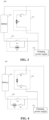
- Fig. 2 illustrates a schematic structural diagram of the connection between a vehicle electrical system 200 of an embodiment of the present application and a charging power supply 100.
- the vehicle electrical system 200 includes a battery 210, a battery heating module 230, and a current control unit 240, wherein one end of the current control unit 240 is connected to the battery 210 and the other end is connected to the charging power supply 100; and the battery heating module 230 is connected in parallel with the battery 210 and the current control unit 240, one end of the battery heating module 230 being connected to the battery 210 and the charging power supply 100, and the other end being connected to the current control unit 240 and the charging power supply 100.
- the battery heating module 230 includes a third relay K3 and a heater R1, the third relay K3 being connected in series with the heater R1, wherein the third relay K3 is used for controlling the battery heating module 230 to be connected into or connected out of the circuit, and the heater R1 is used for heating the battery 210, which may be a PTC heater or a heating film.
- the battery 210 which may be a PTC heater or a heating film.
- the battery heating module 230 may further include a fourth relay K4, wherein the third relay K3, the fourth relay K4, and the heater R1 are connected in series, and the third relay K3 and the fourth relay K4 are provided at both ends of the heater R1, respectively.
- the third relay K3 and the fourth relay K4 cooperate to control the battery heating module 230 to be connected into or out of the circuit, which enhances the safety and reliability of the circuit system.
- the current control unit 240 includes a semiconductor device.
- the current control unit 240 includes a first relay K1 and a semiconductor device D1, wherein one end of the first relay K1 is connected to the battery 210 and the other end of the first relay K1 is connected to the charging power supply 100; and the semiconductor device D1 is connected in parallel with the first relay K1.
- the current control unit 240 includes the first relay K1 and the semiconductor device D1, and may further include a second relay K2, wherein one end of the first relay K1 is connected to the battery 210 and the other end of the first relay K1 is connected to the charging power supply 100; the semiconductor device D1 is connected in parallel with the first relay K1; and the second relay K2 is connected to a branch where the semiconductor device D1 is located.
- the semiconductor device D1 in the current control unit 240 may be set as a diode, a silicon controlled rectifier, a bidirectional IGBT or other semiconductor devices, that is, with the unidirectional conductivity of the semiconductor, by reversely connecting the semiconductor device D1 in the circuit, current blocking can be achieved; and by adjusting the direction of connection of the semiconductor device D 1 in the circuit, the current control unit 240 can be arranged on the positive bus or the negative bus of the battery 210.
- the embodiment of the present application takes the case where the current control unit 240 is disposed on the negative bus of the battery 210 as an example.
- the semiconductor device D1 in the current control unit 240 may be a bidirectional semiconductor device.
- Fig. 5 illustrates a charging control method 500 according to an embodiment of the present application, which is used for heating and charging the battery 210.
- the method 500 may specifically include some or all of the following steps.
- Step 510 controlling, when the temperature of the battery is below a first preset temperature, the current control unit to be in a first state.
- the first state is a state in which the semiconductor device is reversely connected into a circuit.
- the first preset temperature is the allowable temperature for charging the battery 210, and when the temperature of the battery 210 is below the first preset temperature, the battery 210 is in a low-temperature state and needs to be heated before charging.
- the first relay K1 is turned off to reversely connect the semiconductor device D1 into the circuit, thereby controlling the current control unit 240 to block the passage of current, so that the charging power supply 100 stops charging the battery 210, and at the same time, the charging power supply 100 forms a loop with the battery heating module 230, so that the charging power supply 100 supplies power to the battery heating module 230 to heat the battery 210.
- the current control unit 240 further includes the second relay K2.
- the first relay K1 is turned off and the second relay K2 is turned on to reversely connect the semiconductor device D 1 into the circuit, thereby controlling the current control unit 240 to block the passage of current.
- the semiconductor device D1 in the current control unit 240 is a bidirectional semiconductor device, it is possible to directly control to keep the direction of the bidirectional semiconductor device D1 in the circuit in the reverse direction with respect to the current, thereby blocking the passage of the current.
- the battery heating module 230 is connected into the circuit to form a loop with the charging power supply 100.
- the third relay K3 and the fourth relay K4 are turned on, so that the charging power supply 100 supplies power to the battery heating module 230 to heat the battery 210.
- Step 520 sending a first charging request.
- the first charging request includes a first charging current, which is a current required to heat the battery to the first preset temperature, and may be set according to the power of an electrical appliance such as a battery heating module. Specifically, at this time, the charging power supply 100 is requested to send the first charging current to heat the battery 210 to the first preset temperature, so that conventional charging can be performed on the battery 210 subsequently.
- a first charging current which is a current required to heat the battery to the first preset temperature
- the first charging current output by the charging power supply 100 flows into the vehicle electrical system 200. Since the semiconductor device is reversely connected into the circuit, the current control unit 240 is in the first state, that is, the current control unit 240 can block the passage of current, the first charging current can flow into the battery heating module 230 to heat the battery 210 without flowing into the battery 210, thus avoiding damages to the battery. In addition, since the battery 210 remains in conduction with the circuit of the charging power supply 100, the vehicle electrical system 200 can successfully establish a connection with the charging power supply 100 and request the charging current without the need to additionally add or modify the communication protocol.
- Step 530 controlling, when the temperature of the battery reaches the first preset temperature, the current control unit to be in a second state.
- the second state is a state in which the semiconductor device is connected out of the circuit or a state in which the semiconductor device is forwardly connected into the circuit.
- the first relay K1 is turned on to connect the semiconductor device out of the circuit, that is, the semiconductor device D1 is short-circuited, so that the current control unit 240 is controlled to allow the passage of current.
- the current control unit 240 further includes the second relay K2.
- the first relay is turned on and the second relay K2 is turned off to connect the semiconductor device D1 out of the circuit, that is, the semiconductor device D1 is bypassed, thereby controlling the current control unit 240 to allow the passage of current.
- the semiconductor device D1 in the current control unit 240 is a bidirectional semiconductor device, it is possible to directly control to keep the direction of the bidirectional semiconductor device D1 in the circuit in the forward direction with respect to the current, thereby allowing the passage of the current.
- the battery heating module 230 is connected out of the circuit. Specifically, the third relay K3 in the battery heating module 230 is turned off or the third relay K3 and the fourth relay K4 are turned off at the same time, so as to bypass the current heating module 230, so that the charging power supply 100 performs conventional charging on the battery 210.
- Step 540 sending a second charging request.
- the second charging request includes a second charging current.
- the charging power supply 100 is requested to send the second charging current according to the charging demand of the battery 210 to charge the battery 210.
- the battery heating module 230 is bypassed and the current control unit 240 is in the second state, that is, the current control unit 240 allows the passage of current, and the second charging current output by the charging power supply 100 can flow to the battery 210 for conventional charging.
- a current control unit is provided in the vehicle electrical system.
- the semiconductor device When the temperature of the battery is below the first preset temperature and thus the battery needs to be heated, the semiconductor device is controlled to be reversely connected into the circuit, and thus the current control unit is in the first state, that is, the current control unit blocks the passage of current.
- the current control unit blocks the passage of current.
- the semiconductor device When the temperature of the battery is detected to reach the first preset temperature and thus charging is allowed, the semiconductor device is controlled to be connected out of the circuit or forwardly connected into the circuit, so that the current control unit is in the second state, i.e., the current control unit allows passage of current. In this way, when the temperature of the battery reaches the temperature at which charging is allowed, the vehicle electrical system can be directly put into the normal fast charging state without affecting the charging efficiency of the battery.
- the charging power supply can perform safe and efficient low-temperature heating and charging of the low-temperature and low-SOC battery.
- the charging control method in the above embodiment may be extended to the charging control method 600 shown in Fig. 6 , and the method 600 may specifically include some or all of the following steps.
- Step 610 controlling, when the temperature of the battery is below a first preset temperature, the current control unit to be in a first state.
- the first state is a state in which the semiconductor device is reversely connected into a circuit.
- the specific execution is similar to that in the method 500 and will not be repeated here.
- Step 620 sending a first charging request.
- the first charging request includes a first charging current, which is a current required to heat the battery to the first preset temperature, and may be set according to the power of an electrical appliance such as a battery heating module. Specifically, at this time, the charging power supply 100 is requested to send the first charging current to heat the battery 210 to the first preset temperature, so that conventional charging can be performed on the battery 210 subsequently.
- a first charging current which is a current required to heat the battery to the first preset temperature
- Step 630 sending the first charging request when the temperature of the battery reaches the first preset temperature, which includes: the first charging current being 0.
- the first charging current output from the charging power supply 100 is requested to be reduced to 0, and then the working state of the current control unit 240 is switched to the second state, that is, during the switch of the working state of the current control unit 240, the charging current for heating is reduced to 0, which prevents the power battery from being damaged due to the current flowing into the power battery in the process of switching the working state of the current control unit, thus further ensuring the safety of low-temperature charging of the battery.
- Step 640 controlling the current control unit to be in the second state.
- the second state is a state in which the semiconductor device is connected out of the circuit or a state in which the semiconductor device is forwardly connected into the circuit.
- the specific execution is the same as that in the method 500 and will not be repeated here.
- Step 650 sending a second charging request.
- the second charging request includes a second charging current.
- the charging power supply 100 is requested to send the second charging current according to the charging demand of the battery 210 to charge the battery 210.
- the first charging current is requested to be 0, and then the current control unit is controlled to be in the second state, that is, during the switch of the working state of the current control unit, the charging current is reduced to 0, which prevents the power battery from being damaged due to the current flowing into the power battery in the process of switching the working state of the current control unit, thus further ensuring the safety of low-temperature charging of the battery.
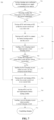
- Fig. 7 illustrates a schematic flow chart of a possible implementation based on the above charging control method, wherein by controlling the working state of the current control unit, the charging power supply can perform safe and efficient low-temperature charging of low-temperature and low-SOC batteries.
- the method 700 may specifically include the following steps:
- Step 701 starting charging upon confirming that the charging power supply is connected to the vehicle.
- Step 702 detecting whether the temperature of the battery meets the first preset temperature.
- the first preset temperature is the allowable temperature for charging the battery 210. If the temperature of the battery 210 meets the first preset temperature, the battery 210 does not need to be heated, and the process proceeds to step 708; and if the temperature of the battery 210 does not meet the first preset temperature, the process proceeds to step 703 to heat the battery 210.
- Step 703 turning off K1 and turning on K2, so that the current control unit is in the first state.
- the first state is a state in which the semiconductor device is reversely connected into a circuit. At this time, the first relay K1 is turned off and the second relay K2 is turned on.
- Step 704 turning on K3 and K4 to connect the battery heating module into the circuit.
- Step 705 sending a first charging request, which includes: a first charging current.
- the first charging current is a current required to heat the battery 210 to the first preset temperature, and may be set according to the power of the battery heating module 230. At this time, the charging power supply 100 is requested to send the first charging current to heat the battery 210 to the first preset temperature, so that conventional charging can be performed on the battery 210 subsequently.
- Step 706 detecting whether the temperature of the battery meets the first preset temperature.
- step 707 After the battery 210 is heated, detection of the heating effect is performed. If the temperature of the battery 210 meets the first preset temperature, heating is stopped, and the process proceeds to step 707; and if not, the heating of the battery 210 is continued, and the process proceeds to step 703.
- Step 707 sending the first charging request, which includes: the first charging current being 0.
- the first charging current output from the charging power supply 100 is requested to be reduced to 0, and then the working state of the current control unit 240 is switched to the second state, that is, during the switch of the working state of the current control unit 240, the charging current is reduced to 0.
- Step 708 closing K1 and turning off K2, so that the current control unit is in the second state.
- the second state is a state in which the semiconductor device is connected out of the circuit. At this time, the first relay K1 is turned on and the second relay K2 is turned off.
- Step 709 turning off K3 and K4, and bypassing the battery heating module.
- Step 710 sending a second charging request, which includes: a second charging current.
- the battery heating module is bypassed and the current control unit 240 is in the second state, that is, the passage of current is allowed, and the charging power supply 100 is requested to output the second charging current to perform conventional charging on the battery 210.
- Step 711 completing charging.
- An embodiment of the present application further provides a vehicle electrical system, including a current control unit, a control module, and a communication module.
- the current control unit includes a semiconductor device, and one end of the current control unit is connected to a battery and the other end is connected to a charging power supply; the control module is used for controlling, when the temperature of the battery is below a first preset temperature, the current control unit to be in a first state, wherein the first state is a state in which the semiconductor device is reversely connected into a circuit; and the communication module is used for sending a first charging request, wherein the first charging request includes a first charging current, which is a current required to heat the battery to the first preset temperature.
- the control module is further used for controlling, when the temperature of the battery reaches the first preset temperature, the current control unit to be in a second state, wherein the second state is a state in which the semiconductor device is connected out of the circuit; and the communication module is further used for sending a second charging request, wherein the second charging request includes a second charging current at which the battery is charged.
- control module is connected to the battery heating module 230 and the current control unit 240 in the vehicle electrical system 200 for use in controlling the turning on and off of K1, K2, K3, and K4, thereby controlling the battery heating module 230 to be connected into the circuit or to be bypassed, as well as controlling the current control unit 240 to be in the first state or the second state.
- the communication module is used for information interaction with the charging power supply 100, and the communication manner includes, but is not limited to, controller area network (CAN) communication or daisy chain communication.
- CAN controller area network
- an embodiment of the present application further provides a battery management module 220, including a processor 221 and a memory 222, wherein the memory 222 is used for storing a computer program, and the processor 221 is used for invoking the computer program to execute the charging control method in any one of the aforementioned embodiments of the present application.
- An embodiment of the present application further provides a readable storage medium for storing a computer program, wherein the computer program is used for executing the charging control method in any one of the aforementioned embodiments of the present application.
- An embodiment of the present application further provides a vehicle, including the vehicle electrical system in any one of the aforementioned embodiments of the present application.
Abstract
The present application provides a battery charging method and a vehicle electrical system that enable charging piles to safely and efficiently charge low-SOC power batteries in low-temperature environments. The battery charging control method is applicable to a vehicle electrical system, wherein the system includes a current control unit that includes a semiconductor device. The method includes: controlling, when the temperature of the battery is below a first preset temperature, the current control unit to be in a first state, wherein the first state includes a state in which the semiconductor device is reversely connected into a circuit; sending a first charging request, wherein the first charging request includes a first charging current; controlling, when the temperature of the battery reaches the first preset temperature, the current control unit to be in a second state, wherein the second state includes a state in which the semiconductor device is connected out of the circuit or a state in which the semiconductor device is forwardly connected into the circuit; and sending a second charging request, wherein the second charging request includes a second charging current at which the battery is charged.
Description
- The present application claims priority to
Chinese patent application 202111631807.1 filed on December 29, 2021 - The present application relates to the technical field of batteries and, in particular, to a battery charging method and a vehicle electrical system.
- With the rapid development of new energy batteries, electric vehicles have become a new direction for the future development of the automotive industry. Power battery technology is becoming more and more mature, and users have higher requirements for the charging speed and safety of power batteries. However, the current commonly used charging piles cannot safely and efficiently charge low state-of-charge (SOC) power batteries in low-temperature environments, which limits the functions and application of the charging piles.
- The present application provides a battery charging method and a vehicle electrical system that enable charging piles to safely and efficiently charge low-SOC power batteries in low-temperature environments.
- In a first aspect, the present application provides a battery charging control method that is applicable to a vehicle electrical system. The vehicle electrical system includes a current control unit that includes a semiconductor device, one end of the current control unit being connected to a battery and the other end being connected to a charging power supply. The battery charging control method includes: controlling, when the temperature of the battery is below a first preset temperature, the current control unit to be in a first state, wherein the first state includes a state in which the semiconductor device is reversely connected into a circuit; sending a first charging request, wherein the first charging request includes a first charging current, which is a current required to heat the battery to the first preset temperature; controlling, when the temperature of the battery reaches the first preset temperature, the current control unit to be in a second state, wherein the second state includes a state in which the semiconductor device is connected out of the circuit or a state in which the semiconductor device is forwardly connected into the circuit; and sending a second charging request, wherein the second charging request includes a second charging current at which the battery is charged.
- The embodiments of the present application can implement a battery charging method in which the working state of a current control unit is switched to be in a first state or a second state according to the temperature condition of the battery. When the temperature of the battery is below the first preset temperature, the current control unit is controlled to be in the first state in which the semiconductor device is reversely connected into the circuit, and at this point the current control unit is capable of blocking the passage of current, so that the charging power supply stops charging the power battery and the charging power supply forms a loop with a battery heating module to supply power to the battery heating module to heat the battery; and when the temperature of the battery reaches the first preset temperature, the current control unit is controlled to be in the second state in which the semiconductor device is connected out of the circuit or forwardly connected into the circuit, and at this point the current control unit allows the passage of current, so that the charging power supply forms a loop with the power battery and the current control unit to charge the power battery and the charging power supply is disconnected from the battery heating module and stops supplying power to the battery heating module. In this way, it is possible to request the charging current for heating during the process of low-temperature charging of the battery without changing the communication protocol, and at the same time, it is possible to effectively ensure that the charging current for heating does not flow into the power battery, thus avoiding damages to the battery; and after the battery is heated to room temperature or the required working temperature of the battery, by switching the current control unit for conventional fast charging, the charging power supply can perform safe and efficient low-temperature charging of low-temperature and low-SOC batteries.
- In a possible embodiment, controlling, when the temperature of the battery reaches the first preset temperature, the current control unit to be in the second state includes: sending the first charging request when the temperature of the battery reaches the first preset temperature, wherein the first charging request includes: the first charging current being 0.
- In the above embodiment, when the battery has been heated to the first preset temperature, the first charging current is requested to be 0, and then the current control unit is controlled to switch to the second state, that is, during the switch of the working state of the current control unit, the charging current for heating is reduced to 0, which prevents the battery from being damaged due to the current flowing into the battery in the process of switching the working state of the current control unit, thus further ensuring the safety of low-temperature charging of the battery.
- In a possible embodiment, the current control unit includes the semiconductor device and a first relay, and controlling, when the temperature of the battery is below the first preset temperature, the current control unit to be in the first state includes: controlling, when the temperature of the battery is below the first preset temperature, the first relay to be turned off, wherein one end of the first relay is connected to the battery and the other end of the first relay is connected to the charging power supply, and the semiconductor device is connected in parallel with the first relay.
- In a possible embodiment, the current control unit includes the semiconductor device and a first relay, and controlling, when the temperature of the battery reaches the first preset temperature, the current control unit to be in the second state includes: controlling, when the temperature of the battery reaches the first preset temperature, the first relay to be turned on, wherein one end of the first relay is connected to the battery and the other end of the first relay is connected to the charging power supply, and the semiconductor device is connected in parallel with the first relay.
- In the above embodiments, the current control unit includes the first relay and the semiconductor device, and the first relay is connected in parallel with the semiconductor device. When the first relay is turned off, the semiconductor device is reversely connected into the circuit, so that the current control unit is in the first state; and when the first relay is turned on, the semiconductor device may be bypassed, so that the current control unit is in the second state. By controlling the turning on or off of the first relay, the connection of the semiconductor device into and out of the circuit can be realized, thus switching the working state of the current control unit.
- In a possible embodiment, the current control unit includes a bidirectional semiconductor device, and controlling, when the temperature of the battery reaches the first preset temperature, the current control unit to be in the second state includes: controlling, when the temperature of the battery reaches the first preset temperature, the bidirectional semiconductor device to be commutated, so that the bidirectional semiconductor device is forwardly connected into the circuit.
- In the above embodiment, the current control unit includes the bidirectional semiconductor device, and by controlling and switching the direction of the bidirectional semiconductor device, it is possible to achieve the reverse connection into the circuit when the temperature of the battery is below the first preset temperature and the forward connection into the circuit when the temperature of the battery reaches the first preset temperature, which saves the relay in the current control unit and makes the connection and control of the circuit simpler, thus ensuring fast and efficient switching of the working state of the current control unit.
- In a second aspect, the present application provides a vehicle electrical system, including: a current control unit that includes a semiconductor device, one end of the current control unit being connected to a battery and the other end being connected to a charging power supply; a control module for controlling, when the temperature of the battery is below a first preset temperature, the current control unit to be in a first state, wherein the first state includes a state in which the semiconductor device is reversely connected into a circuit; and a communication module for sending a first charging request, wherein the first charging request includes a first charging current, which is a current required to heat the battery to the first preset temperature, wherein the control module is further used for controlling, when the temperature of the battery reaches the first preset temperature, the current control unit to be in a second state, wherein the second state includes a state in which the semiconductor device is connected out of the circuit or a state in which the semiconductor device is forwardly connected into the circuit; and the communication module is further used for sending a second charging request, wherein the second charging request includes a second charging current at which the battery is charged.
- The above embodiment provides a vehicle electrical system, and by using a current control unit in the vehicle electrical system, the working state of the current control unit is made to be in a first state or a second state according to the temperature condition of the battery. When the temperature of the battery is below a first preset temperature, the current control unit is in the first state in which the semiconductor device is reversely connected into the circuit, and at this point the current control unit is capable of blocking the passage of current, so that the charging power supply forms a loop with a battery heating module to supply power to the battery heating module to heat the battery; and when the temperature of the battery reaches the first preset temperature, the current control unit is in the second state in which the semiconductor device is connected out of the circuit or forwardly connected into the circuit, and at this point the current control unit allows the passage of current, so that the charging power supply forms a loop with the power battery and the current control unit to perform conventional charging on the power battery, and the charging power supply is disconnected from the battery heating module and thus stops supplying power to the battery heating module. In this way, it is possible to request the charging current for heating during the process of low-temperature charging of the battery without changing the communication protocol, and at the same time, it is possible to effectively ensure that the charging current for heating does not flow into the power battery, thus avoiding damages to the battery; and after the battery is heated to room temperature or the required working temperature of the battery, by switching the current control unit for conventional fast charging, the charging pile can perform safe and efficient low-temperature charging of low-temperature and low-SOC batteries.
- In a possible embodiment, the communication module is further used for sending the first charging request when the temperature of the battery reaches the first preset temperature, wherein the first charging request includes: the first charging current being 0.
- In the above embodiment, when the battery has been heated to the first preset temperature, the communication module requests the first charging current to be 0, and then the control module controls the current control unit to be in the second state, that is, during the switch of the working state of the current control unit, the charging current is reduced to 0, which prevents the battery from being damaged due to the current flowing into the battery in the process of switching the working state of the current control unit, thus further ensuring the safety of low-temperature charging of the battery.
- In a third aspect, the present application provides a vehicle electrical system including a battery and a current control unit that includes a first relay and a semiconductor device, one end of the first relay being connected to the battery and the other end of the first relay being connected to a charging power supply; and the semiconductor device being connected in parallel with the first relay, wherein when the temperature of the battery is below the first preset temperature, the current control unit is in a first state in which the first relay is turned off; and when the temperature of the battery reaches the first preset temperature, the current control unit is in a second state in which the first relay is turned on.
- In a possible embodiment, the above current control unit includes: the first relay, the semiconductor device, and a second relay, one end of the first relay being connected to the battery and the other end of the first relay being connected to the charging power supply; the semiconductor device being connected in parallel with the first relay; and the second relay being connected to a branch where the semiconductor device is located, wherein when the temperature of the battery is below the first preset temperature, the current control unit is in the first state in which the first relay is turned off and the second relay is turned on; and when the temperature of the battery reaches the first preset temperature, the current control unit is in a second state in which the first relay is turned on and the second relay is turned off.
- In the above embodiment, the current control unit includes the first relay and the semiconductor device, and further includes the second relay, wherein the second relay is connected to the branch where the semiconductor device is located and is connected in series with the semiconductor device, and is capable of controlling the connection of the semiconductor device into and out of the circuit. By using the first relay connected in parallel with the semiconductor device and the second relay connected in series with the semiconductor device to simultaneously control the connection of the semiconductor device into and out of the circuit, the safety of the circuit can be improved. When the relay on either branch fails or malfunctions, the relay on the other branch is capable of continuing to work, which ensures the switching of the connection of the semiconductor device into and out of the circuit, thus increasing the reliability of this electrical system.
- In a fourth aspect, the present application provides a battery management system including a processor and a memory, wherein the memory is used for storing a computer program, and the processor is used for invoking the computer program to execute the method of any one of the possible embodiments in the first aspect described above.
- In a fifth aspect, the present application provides a storage medium for storing a computer program, wherein the computer program is used for executing the method of any one of the possible embodiments in the first aspect described above.
- In a sixth aspect, the present application provides a vehicle including the vehicle electrical system of any one of the possible embodiments in the first aspect and the second aspect described above.
- In order to illustrate the technical solutions of the embodiments of the present application more clearly, the following briefly introduces the drawings required in the embodiments of the present application. Obviously, the drawings described below are only some embodiments of the present application. For those of ordinary skill in the art, other drawings may also be obtained according to the drawings without any creative effort.
-
Fig. 1 is a schematic structural diagram of a charging system disclosed in an embodiment of the present application; -
Fig. 2 is a schematic structural diagram of the connection between a vehicle electrical system disclosed in an embodiment of the present application and a charging power supply; -
Fig. 3 is a schematic structural diagram of the connection between another vehicle electrical system disclosed in an embodiment of the present application and a charging power supply; -
Fig. 4 is a schematic structural diagram of the connection between yet another vehicle electrical system disclosed in an embodiment of the present application and a charging power supply; -
Fig. 5 is a schematic flow chart of a battery charging control method disclosed in an embodiment of the present application; -
Fig. 6 is a schematic flow chart of another battery charging control method disclosed in an embodiment of the present application; -
Fig. 7 is a schematic flow chart of yet another battery charging control method disclosed in an embodiment of the present application; and -
Fig. 8 is a schematic structural diagram of a battery management module disclosed in an embodiment of the present application. - The implementations of the present application need to be further described in detail below with reference to the accompanying drawings and embodiments. The following detailed description of the embodiments and the accompanying drawings are used to illustrate the principles of the present application by way of example, but should not be used to limit the scope of the present application, that is, the present application is not limited to the described embodiments.
- In the description of the present application, it should be noted that unless otherwise specified, "multiple" means more than two; the orientation or location relationships indicated by the terms "up," "down," "left," "right," "inside," "outside," etc., are only for convenience and simplification of the description of the present application, but do not indicate or imply that the devices or elements referred to must have a particular orientation, be constructed and operate in a particular orientation, and therefore cannot be construed as a limitation of the present application. In addition, the terms "first," "second" and "third" are only used for descriptive purposes, and cannot be construed as indicating or implying relative importance. "Vertical" does not mean being vertical in the strict sense, but within the allowable range of error. "Parallel" does not mean being parallel in the strict sense, but within the allowable range of error.
- Orientation words appearing in the following description are all directions shown in the drawings, and do not limit the specific structure of the present application. In the description of the present application, it should also be noted that, unless otherwise expressly specified and defined, the terms "install," "connected" and "connect" should be understood in a broad sense, for example, they may be fixedly connected, detachably connected or integrally connected; and they may be directly connected or indirectly connected through an intermediate medium. For those of ordinary skill in the art, the specific meanings of the above terms in the present application may be understood according to specific circumstances.
-
Fig. 1 illustrates a schematic structural diagram of a charging system to which embodiments of the present application are applicable. - As shown in
Fig. 1 , thecharging system 10 may include: acharging power supply 100 and a vehicleelectrical system 200. Optionally, the vehicle may be an electric vehicle, including an all-electric vehicle and a plug-in hybrid electric vehicle. - Optionally, at least one battery pack may be provided in the vehicle
electrical system 200, and the at least one battery pack as a whole may be collectively referred to as a power battery, i.e., abattery 210. In terms of the type of the battery, this power battery may be any type of battery, including but not limited to: lithium ion battery, lithium metal battery, lithium sulfur battery, lead acid battery, nickel cadmium battery, nickel metal hydride battery, or lithium air battery and the like. In terms of the scale of the battery, the power battery in the embodiments of the present application may be a battery cell/cell, or a battery module or a battery pack, wherein the battery module or battery pack may be formed by multiple batteries connected in series or parallel. In the embodiments of the present application, no specific limitation is imposed on the specific type and scale of the power battery. - In addition, in order to intelligently manage and maintain the power battery, to prevent the battery from overcharging and overdischarging, and to prolong the service life of the battery, the vehicle
electrical system 200 is generally provided with abattery management module 220 for controlling the vehicle electrical system and monitoring the state of thebattery 210. The battery management module may be a battery management system (BMS) or a domain control unit (DCU). Optionally, thebattery management module 220 may be integrated with the power battery and provided in the same equipment or device, or thebattery management module 220 may also be provided outside the power battery as an independent equipment/device. - Specifically, the charging
power supply 100 is a device for supplementing electric energy for thebattery 210 in the vehicleelectrical system 200. The chargingpower supply 100 in the embodiments of the present application may be a fast charging pile, a charging pile supporting a vehicle to grid (V2G) mode, or the like. - Optionally, the charging
power supply 100 may be connected to thebattery 210 through an electric wire, and connected to thebattery management module 220 through a communication wire, wherein the communication wire is used to realize information interaction between the chargingpower supply 100 and thebattery management module 220. - As an example, the communication wire includes, but is not limited to, a controller area network (CAN) communication bus or a daisy chain communication bus.
- Optionally, in addition to communicating with the
battery management module 220 through a communication wire, the chargingpower supply 100 may also communicate with thebattery management module 220 through a wireless network. In the embodiments of the present application, no specific limitation is imposed on the type of communication between the chargingpower supply 100 and thebattery management module 220. - The power batteries for new energy vehicles on the market are mostly rechargeable storage batteries, and the most common ones are lithium batteries, such as lithium-ion batteries or lithium-ion polymer batteries, and the like. The temperature of the battery and the uniformity of the temperature field have a great influence on the performance and service life of the power battery. If the power battery works at too low a temperature or the power battery is charged in a low-temperature environment, lithium plating in the battery may be caused, resulting in performance degradation of the battery, which seriously affects the capacity and service life of the battery. Therefore, when the battery is charged in a low-temperature environment, the battery needs to be heated first.
- At present, when the battery is in a low-temperature environment, if the battery is in a low-SOC state, it cannot be discharged to the outside world and the battery heating module cannot work. In this case, the battery heating module can only be powered by means of slow charging through the on-board charger, so as to heat the battery, and after the temperature of the battery rises to a certain value, the battery can be charged normally. However, this method has its limitations, as there are no slow charging ports on some vehicles, and it is impossible to supply power to the battery heating module by means of slow charging through the on-board charger. For example, when a commercial vehicle has only a fast charging port, the vehicle may be unchargeable and unusable in the case of low-temperature and low-SOC batteries.
- For a fast charging pile, the conventional heating and charging method requires the change of the communication protocol so that the pile can recognize that the vehicle is in a low-temperature environment, thus enabling the pile to have the auxiliary heating function. When this method requires the development of a new fast charging pile and additional addition or modification of the communication protocol during charging, the standard international protocol is not applicable, and the existing fast charging piles on the market still cannot be widely used.
- Therefore, in order to solve the above problem and enable the charging piles to safely and efficiently charge low-SOC power batteries in low-temperature environments, embodiments of the present application provide a battery charging control method and a vehicle electrical system.
-
Fig. 2 illustrates a schematic structural diagram of the connection between a vehicleelectrical system 200 of an embodiment of the present application and a chargingpower supply 100. The vehicleelectrical system 200 includes abattery 210, abattery heating module 230, and acurrent control unit 240, wherein one end of thecurrent control unit 240 is connected to thebattery 210 and the other end is connected to the chargingpower supply 100; and thebattery heating module 230 is connected in parallel with thebattery 210 and thecurrent control unit 240, one end of thebattery heating module 230 being connected to thebattery 210 and the chargingpower supply 100, and the other end being connected to thecurrent control unit 240 and the chargingpower supply 100. - Optionally, as shown in
Fig. 3 , thebattery heating module 230 includes a third relay K3 and a heater R1, the third relay K3 being connected in series with the heater R1, wherein the third relay K3 is used for controlling thebattery heating module 230 to be connected into or connected out of the circuit, and the heater R1 is used for heating thebattery 210, which may be a PTC heater or a heating film. In the embodiments of the present application, no specific limitation is imposed on either the specific type or scale of the heater in thebattery heating module 230. - Optionally, as shown in
Fig. 4 , thebattery heating module 230 may further include a fourth relay K4, wherein the third relay K3, the fourth relay K4, and the heater R1 are connected in series, and the third relay K3 and the fourth relay K4 are provided at both ends of the heater R1, respectively. The third relay K3 and the fourth relay K4 cooperate to control thebattery heating module 230 to be connected into or out of the circuit, which enhances the safety and reliability of the circuit system. - The
current control unit 240 includes a semiconductor device. Optionally, as shown inFig. 3 , thecurrent control unit 240 includes a first relay K1 and a semiconductor device D1, wherein one end of the first relay K1 is connected to thebattery 210 and the other end of the first relay K1 is connected to the chargingpower supply 100; and the semiconductor device D1 is connected in parallel with the first relay K1. - Optionally, as shown in
Fig. 4 , thecurrent control unit 240 includes the first relay K1 and the semiconductor device D1, and may further include a second relay K2, wherein one end of the first relay K1 is connected to thebattery 210 and the other end of the first relay K1 is connected to the chargingpower supply 100; the semiconductor device D1 is connected in parallel with the first relay K1; and the second relay K2 is connected to a branch where the semiconductor device D1 is located. - Optionally, the semiconductor device D1 in the
current control unit 240 may be set as a diode, a silicon controlled rectifier, a bidirectional IGBT or other semiconductor devices, that is, with the unidirectional conductivity of the semiconductor, by reversely connecting the semiconductor device D1 in the circuit, current blocking can be achieved; and by adjusting the direction of connection of the semiconductor device D 1 in the circuit, thecurrent control unit 240 can be arranged on the positive bus or the negative bus of thebattery 210. The embodiment of the present application takes the case where thecurrent control unit 240 is disposed on the negative bus of thebattery 210 as an example. - Optionally, the semiconductor device D1 in the
current control unit 240 may be a bidirectional semiconductor device. -
Fig. 5 illustrates a chargingcontrol method 500 according to an embodiment of the present application, which is used for heating and charging thebattery 210. Themethod 500 may specifically include some or all of the following steps. - Step 510: controlling, when the temperature of the battery is below a first preset temperature, the current control unit to be in a first state.
- Here, the first state is a state in which the semiconductor device is reversely connected into a circuit. Specifically, the first preset temperature is the allowable temperature for charging the
battery 210, and when the temperature of thebattery 210 is below the first preset temperature, thebattery 210 is in a low-temperature state and needs to be heated before charging. In this case, the first relay K1 is turned off to reversely connect the semiconductor device D1 into the circuit, thereby controlling thecurrent control unit 240 to block the passage of current, so that the chargingpower supply 100 stops charging thebattery 210, and at the same time, the chargingpower supply 100 forms a loop with thebattery heating module 230, so that the chargingpower supply 100 supplies power to thebattery heating module 230 to heat thebattery 210. - Optionally, as shown in
Fig. 4 , thecurrent control unit 240 further includes the second relay K2. When the temperature of thebattery 210 is below the first preset temperature, the first relay K1 is turned off and the second relay K2 is turned on to reversely connect the semiconductor device D 1 into the circuit, thereby controlling thecurrent control unit 240 to block the passage of current. - Optionally, when the semiconductor device D1 in the
current control unit 240 is a bidirectional semiconductor device, it is possible to directly control to keep the direction of the bidirectional semiconductor device D1 in the circuit in the reverse direction with respect to the current, thereby blocking the passage of the current. - When the
current control unit 240 is in the first state, thebattery heating module 230 is connected into the circuit to form a loop with the chargingpower supply 100. Specifically, the third relay K3 and the fourth relay K4 are turned on, so that the chargingpower supply 100 supplies power to thebattery heating module 230 to heat thebattery 210. - Step 520: sending a first charging request.
- Here, the first charging request includes a first charging current, which is a current required to heat the battery to the first preset temperature, and may be set according to the power of an electrical appliance such as a battery heating module. Specifically, at this time, the charging
power supply 100 is requested to send the first charging current to heat thebattery 210 to the first preset temperature, so that conventional charging can be performed on thebattery 210 subsequently. - At this time, the first charging current output by the charging
power supply 100 flows into the vehicleelectrical system 200. Since the semiconductor device is reversely connected into the circuit, thecurrent control unit 240 is in the first state, that is, thecurrent control unit 240 can block the passage of current, the first charging current can flow into thebattery heating module 230 to heat thebattery 210 without flowing into thebattery 210, thus avoiding damages to the battery. In addition, since thebattery 210 remains in conduction with the circuit of the chargingpower supply 100, the vehicleelectrical system 200 can successfully establish a connection with the chargingpower supply 100 and request the charging current without the need to additionally add or modify the communication protocol. - Step 530: controlling, when the temperature of the battery reaches the first preset temperature, the current control unit to be in a second state.
- Here, the second state is a state in which the semiconductor device is connected out of the circuit or a state in which the semiconductor device is forwardly connected into the circuit. Specifically, when the temperature of the
battery 210 reaches the first preset temperature, conventional charging may be performed on thebattery 210. At this time, the first relay K1 is turned on to connect the semiconductor device out of the circuit, that is, the semiconductor device D1 is short-circuited, so that thecurrent control unit 240 is controlled to allow the passage of current. - Optionally, as shown in
Fig. 4 , thecurrent control unit 240 further includes the second relay K2. When the temperature of thebattery 210 reaches the first preset temperature, the first relay is turned on and the second relay K2 is turned off to connect the semiconductor device D1 out of the circuit, that is, the semiconductor device D1 is bypassed, thereby controlling thecurrent control unit 240 to allow the passage of current. - Optionally, when the semiconductor device D1 in the
current control unit 240 is a bidirectional semiconductor device, it is possible to directly control to keep the direction of the bidirectional semiconductor device D1 in the circuit in the forward direction with respect to the current, thereby allowing the passage of the current. - At this time, the
battery heating module 230 is connected out of the circuit. Specifically, the third relay K3 in thebattery heating module 230 is turned off or the third relay K3 and the fourth relay K4 are turned off at the same time, so as to bypass thecurrent heating module 230, so that the chargingpower supply 100 performs conventional charging on thebattery 210. - Step 540: sending a second charging request.
- The second charging request includes a second charging current. Specifically, the charging
power supply 100 is requested to send the second charging current according to the charging demand of thebattery 210 to charge thebattery 210. - At this time, the
battery heating module 230 is bypassed and thecurrent control unit 240 is in the second state, that is, thecurrent control unit 240 allows the passage of current, and the second charging current output by the chargingpower supply 100 can flow to thebattery 210 for conventional charging. - In this embodiment, a current control unit is provided in the vehicle electrical system. When the temperature of the battery is below the first preset temperature and thus the battery needs to be heated, the semiconductor device is controlled to be reversely connected into the circuit, and thus the current control unit is in the first state, that is, the current control unit blocks the passage of current. In this way, it is possible to keep the battery to be connected to the charging power supply and successfully request the charging power supply to output charging current without additionally adding or modifying the communication protocol, while effectively preventing the battery from being damaged due to the first charging current output from the charging power supply flowing into the battery. When the temperature of the battery is detected to reach the first preset temperature and thus charging is allowed, the semiconductor device is controlled to be connected out of the circuit or forwardly connected into the circuit, so that the current control unit is in the second state, i.e., the current control unit allows passage of current. In this way, when the temperature of the battery reaches the temperature at which charging is allowed, the vehicle electrical system can be directly put into the normal fast charging state without affecting the charging efficiency of the battery. By setting the current control unit and controlling its working state, the charging power supply can perform safe and efficient low-temperature heating and charging of the low-temperature and low-SOC battery.
- Further, the charging control method in the above embodiment may be extended to the charging
control method 600 shown inFig. 6 , and themethod 600 may specifically include some or all of the following steps. - Step 610: controlling, when the temperature of the battery is below a first preset temperature, the current control unit to be in a first state.
- Here, the first state is a state in which the semiconductor device is reversely connected into a circuit. The specific execution is similar to that in the
method 500 and will not be repeated here. - Step 620: sending a first charging request.
- Here, the first charging request includes a first charging current, which is a current required to heat the battery to the first preset temperature, and may be set according to the power of an electrical appliance such as a battery heating module. Specifically, at this time, the charging
power supply 100 is requested to send the first charging current to heat thebattery 210 to the first preset temperature, so that conventional charging can be performed on thebattery 210 subsequently. - Step 630: sending the first charging request when the temperature of the battery reaches the first preset temperature, which includes: the first charging current being 0.
- Specifically, when the temperature of the battery reaches the first preset temperature, the first charging current output from the charging
power supply 100 is requested to be reduced to 0, and then the working state of thecurrent control unit 240 is switched to the second state, that is, during the switch of the working state of thecurrent control unit 240, the charging current for heating is reduced to 0, which prevents the power battery from being damaged due to the current flowing into the power battery in the process of switching the working state of the current control unit, thus further ensuring the safety of low-temperature charging of the battery. - Step 640: controlling the current control unit to be in the second state.
- Here, the second state is a state in which the semiconductor device is connected out of the circuit or a state in which the semiconductor device is forwardly connected into the circuit. The specific execution is the same as that in the
method 500 and will not be repeated here. - Step 650: sending a second charging request.
- The second charging request includes a second charging current. Specifically, the charging
power supply 100 is requested to send the second charging current according to the charging demand of thebattery 210 to charge thebattery 210. - In this embodiment, when the temperature of the battery has been heated to the first preset temperature, the first charging current is requested to be 0, and then the current control unit is controlled to be in the second state, that is, during the switch of the working state of the current control unit, the charging current is reduced to 0, which prevents the power battery from being damaged due to the current flowing into the power battery in the process of switching the working state of the current control unit, thus further ensuring the safety of low-temperature charging of the battery.
-
Fig. 7 illustrates a schematic flow chart of a possible implementation based on the above charging control method, wherein by controlling the working state of the current control unit, the charging power supply can perform safe and efficient low-temperature charging of low-temperature and low-SOC batteries. Taking the vehicle electrical system illustrated inFig. 4 as an example, themethod 700 may specifically include the following steps: - Step 701: starting charging upon confirming that the charging power supply is connected to the vehicle.
- Step 702: detecting whether the temperature of the battery meets the first preset temperature.
- The first preset temperature is the allowable temperature for charging the
battery 210. If the temperature of thebattery 210 meets the first preset temperature, thebattery 210 does not need to be heated, and the process proceeds to step 708; and if the temperature of thebattery 210 does not meet the first preset temperature, the process proceeds to step 703 to heat thebattery 210. - Step 703: turning off K1 and turning on K2, so that the current control unit is in the first state.
- Here, the first state is a state in which the semiconductor device is reversely connected into a circuit. At this time, the first relay K1 is turned off and the second relay K2 is turned on.
- Step 704: turning on K3 and K4 to connect the battery heating module into the circuit.
- Step 705: sending a first charging request, which includes: a first charging current.
- The first charging current is a current required to heat the
battery 210 to the first preset temperature, and may be set according to the power of thebattery heating module 230. At this time, the chargingpower supply 100 is requested to send the first charging current to heat thebattery 210 to the first preset temperature, so that conventional charging can be performed on thebattery 210 subsequently. - Step 706: detecting whether the temperature of the battery meets the first preset temperature.
- After the
battery 210 is heated, detection of the heating effect is performed. If the temperature of thebattery 210 meets the first preset temperature, heating is stopped, and the process proceeds to step 707; and if not, the heating of thebattery 210 is continued, and the process proceeds to step 703. - Step 707: sending the first charging request, which includes: the first charging current being 0.
- When the temperature of the battery reaches the first preset temperature, the first charging current output from the charging
power supply 100 is requested to be reduced to 0, and then the working state of thecurrent control unit 240 is switched to the second state, that is, during the switch of the working state of thecurrent control unit 240, the charging current is reduced to 0. - Step 708: closing K1 and turning off K2, so that the current control unit is in the second state.
- Here, the second state is a state in which the semiconductor device is connected out of the circuit. At this time, the first relay K1 is turned on and the second relay K2 is turned off.
- Step 709: turning off K3 and K4, and bypassing the battery heating module.
- Step 710: sending a second charging request, which includes: a second charging current.
- At this time, the battery heating module is bypassed and the
current control unit 240 is in the second state, that is, the passage of current is allowed, and the chargingpower supply 100 is requested to output the second charging current to perform conventional charging on thebattery 210. - Step 711: completing charging.
- From the above possible methods, it can be seen that by controlling the working state of the current control unit, it is possible to keep the battery to be connected to the charging power supply and successfully request the charging power supply to output charging current without additionally adding or modifying the communication protocol, while preventing the battery from being damaged due to the current output from the charging power supply flowing into the battery during the process of low-temperature charging, so that the charging power supply can perform safe and efficient low-temperature charging of low-temperature and low-SOC batteries.
- An embodiment of the present application further provides a vehicle electrical system, including a current control unit, a control module, and a communication module. The current control unit includes a semiconductor device, and one end of the current control unit is connected to a battery and the other end is connected to a charging power supply; the control module is used for controlling, when the temperature of the battery is below a first preset temperature, the current control unit to be in a first state, wherein the first state is a state in which the semiconductor device is reversely connected into a circuit; and the communication module is used for sending a first charging request, wherein the first charging request includes a first charging current, which is a current required to heat the battery to the first preset temperature. The control module is further used for controlling, when the temperature of the battery reaches the first preset temperature, the current control unit to be in a second state, wherein the second state is a state in which the semiconductor device is connected out of the circuit; and the communication module is further used for sending a second charging request, wherein the second charging request includes a second charging current at which the battery is charged.
- Specifically, the control module is connected to the
battery heating module 230 and thecurrent control unit 240 in the vehicleelectrical system 200 for use in controlling the turning on and off of K1, K2, K3, and K4, thereby controlling thebattery heating module 230 to be connected into the circuit or to be bypassed, as well as controlling thecurrent control unit 240 to be in the first state or the second state. The communication module is used for information interaction with the chargingpower supply 100, and the communication manner includes, but is not limited to, controller area network (CAN) communication or daisy chain communication. - As shown in
Fig. 8 , an embodiment of the present application further provides abattery management module 220, including aprocessor 221 and amemory 222, wherein thememory 222 is used for storing a computer program, and theprocessor 221 is used for invoking the computer program to execute the charging control method in any one of the aforementioned embodiments of the present application. - An embodiment of the present application further provides a readable storage medium for storing a computer program, wherein the computer program is used for executing the charging control method in any one of the aforementioned embodiments of the present application.
- An embodiment of the present application further provides a vehicle, including the vehicle electrical system in any one of the aforementioned embodiments of the present application.
- It should be understood that the specific examples herein are intended only to assist those skilled in the art to better understand the embodiments of the present application and are not intended to limit the scope of the embodiments of the present application.
- It should also be understood that in the various embodiments of the present application, the order in which the processes are performed shall be determined by their functions and intrinsic logic, and shall not constitute any limitation to the implementation process of the embodiments of the present application. The various implementations described in the present specification may be implemented individually or in combination, which are not limited in the embodiments of the present application.
- Although the present application has been described with reference to the preferred embodiments, various improvements can be made thereto and components thereof can be replaced with equivalents without departing from the scope of the present application. In particular, the various technical features mentioned in the various embodiments can be combined in any way, as long as there is no structural conflict. The present application is not limited to the particular embodiments disclosed herein, but includes all technical solutions that fall within the scope of the claims.
Claims (12)
- A battery charging control method that is applicable to a vehicle electrical system, characterized in that the vehicle electrical system comprises a current control unit that comprises a semiconductor device, one end of the current control unit being connected to a battery and the other end being connected to a charging power supply, the method comprising:controlling, when the temperature of the battery is below a first preset temperature, the current control unit to be in a first state, wherein the first state comprises a state in which the semiconductor device is reversely connected into a circuit;sending a first charging request, wherein the first charging request comprises a first charging current, which is a current required to heat the battery to the first preset temperature;controlling, when the temperature of the battery reaches the first preset temperature, the current control unit to be in a second state, wherein the second state comprises a state in which the semiconductor device is connected out of the circuit or a state in which the semiconductor device is forwardly connected into the circuit; andsending a second charging request, wherein the second charging request comprises a second charging current at which the battery is charged.
- The control method according to claim 1, characterized in that controlling, when the temperature of the battery reaches the first preset temperature, the current control unit to be in the second state comprises:
sending the first charging request when the temperature of the battery reaches the first preset temperature, wherein the first charging request comprises: the first charging current being 0. - The control method according to claim 1 or 2, characterized in that the current control unit comprises the semiconductor device and a first relay, and controlling, when the temperature of the battery is below the first preset temperature, the current control unit to be in the first state comprises:
controlling, when the temperature of the battery is below the first preset temperature, the first relay to be turned off, wherein one end of the first relay is connected to the battery and the other end of the first relay is connected to the charging power supply, and the semiconductor device is connected in parallel with the first relay. - The control method according to any one of claims 1 to 3, characterized in that the current control unit comprises the semiconductor device and a first relay, and controlling, when the temperature of the battery reaches the first preset temperature, the current control unit to be in the second state comprises:
controlling, when the temperature of the battery reaches the first preset temperature, the first relay to be turned on, wherein one end of the first relay is connected to the battery and the other end of the first relay is connected to the charging power supply, and the semiconductor device is connected in parallel with the first relay. - The control method according to claim 1 or 2, characterized in that the current control unit comprises a bidirectional semiconductor device, and controlling, when the temperature of the battery reaches the first preset temperature, the current control unit to be in the second state comprises:
controlling, when the temperature of the battery reaches the first preset temperature, the bidirectional semiconductor device to be commutated, so that the bidirectional semiconductor device is forwardly connected into the circuit. - A vehicle electrical system, characterized in that the system comprises:a current control unit that comprises a semiconductor device, one end of the current control unit being connected to a battery and the other end being connected to a charging power supply;a control module for controlling, when the temperature of the battery is below a first preset temperature, the current control unit to be in a first state, wherein the first state comprises a state in which the semiconductor device is reversely connected into a circuit; anda communication module for sending a first charging request, wherein the first charging request comprises a first charging current, which is a current required to heat the battery to the first preset temperature, whereinthe control module is further used for controlling, when the temperature of the battery reaches the first preset temperature, the current control unit to be in a second state, wherein the second state comprises a state in which the semiconductor device is connected out of the circuit or a state in which the semiconductor device is forwardly connected into the circuit; andthe communication module is further used for sending a second charging request, wherein the second charging request comprises a second charging current at which the battery is charged.
- The system according to claim 6, characterized in that the communication module is further used for sending the first charging request when the temperature of the battery reaches the first preset temperature, wherein the first charging request comprises: the first charging current being 0.
- A vehicle electrical system, characterized in that the system comprises a battery and a current control unit that comprises a first relay and a semiconductor device, one end of the first relay being connected to the battery and the other end of the first relay being connected to a charging power supply; and the semiconductor device being connected in parallel with the first relay, whereinwhen the temperature of the battery is below a first preset temperature, the current control unit is in a first state in which the first relay is turned off; andwhen the temperature of the battery reaches the first preset temperature, the current control unit is in a second state in which the first relay is turned on.
- The system according to claim 8, characterized in that the current control unit comprises the first relay, the semiconductor device, and a second relay, one end of the first relay being connected to the battery and the other end of the first relay being connected to the charging power supply; the semiconductor device being connected in parallel with the first relay; and the second relay being connected to a branch where the semiconductor device is located, whereinwhen the temperature of the battery is below the first preset temperature, the current control unit is in the first state in which the first relay is turned off and the second relay is turned on; andwhen the temperature of the battery reaches the first preset temperature, the current control unit is in the second state in which the first relay is turned on and the second relay is turned off.
- A battery management system, characterized by comprising a processor and a memory, wherein the memory is used for storing a computer program, and the processor is used for invoking the computer program to execute the method according to any one of claims 1 to 5.
- A readable storage medium, characterized in that it is used for storing a computer program, wherein the computer program is used for executing the method according to any one of claims 1 to 5.
- A vehicle, characterized by comprising the vehicle electrical system according to any one of claims 6 to 9.
Applications Claiming Priority (2)
| Application Number | Priority Date | Filing Date | Title |
|---|---|---|---|
| CN202111631807.1A CN116409185A (en) | 2021-12-29 | 2021-12-29 | Battery charging method and vehicle electrical system |
| PCT/CN2022/089334 WO2023123770A1 (en) | 2021-12-29 | 2022-04-26 | Battery charging method and vehicle electric system |
Publications (2)
| Publication Number | Publication Date |
|---|---|
| EP4227149A1 true EP4227149A1 (en) | 2023-08-16 |
| EP4227149A4 EP4227149A4 (en) | 2023-08-16 |
Family
ID=86896252
Family Applications (1)
| Application Number | Title | Priority Date | Filing Date |
|---|---|---|---|
| EP22747232.1A Pending EP4227149A4 (en) | 2021-12-29 | 2022-04-26 | Battery charging method and vehicle electric system |
Country Status (4)
| Country | Link |
|---|---|
| US (1) | US20230208149A1 (en) |
| EP (1) | EP4227149A4 (en) |
| JP (1) | JP2024503767A (en) |
| KR (1) | KR20230106121A (en) |
Families Citing this family (1)
| Publication number | Priority date | Publication date | Assignee | Title |
|---|---|---|---|---|
| CN112912273A (en) * | 2018-10-22 | 2021-06-04 | 松下知识产权经营株式会社 | Control device for temperature control device |
Family Cites Families (5)
| Publication number | Priority date | Publication date | Assignee | Title |
|---|---|---|---|---|
| CN106965700A (en) * | 2017-04-28 | 2017-07-21 | 北京新能源汽车股份有限公司 | A kind of electric automobile heating charging circuit and charging method |
| EP3575124A1 (en) * | 2018-05-29 | 2019-12-04 | Siemens Mobility GmbH | Drive system for a rail vehicle with a primary transformer-side short-circuit protection device |
| CN110435478A (en) * | 2019-07-11 | 2019-11-12 | 桑顿新能源科技(长沙)有限公司 | A kind of power battery charging system, charging method and electric car |
| CN214672757U (en) * | 2021-03-29 | 2021-11-09 | 郑州比克新动力科技有限公司 | Automatic heating system for battery pack |
| CN113746171A (en) * | 2021-09-03 | 2021-12-03 | 北京科易动力科技有限公司 | Battery circuit and control method thereof |
-
2022
- 2022-04-26 JP JP2022548238A patent/JP2024503767A/en active Pending
- 2022-04-26 EP EP22747232.1A patent/EP4227149A4/en active Pending
- 2022-04-26 KR KR1020227027718A patent/KR20230106121A/en not_active Application Discontinuation
- 2022-09-08 US US17/940,318 patent/US20230208149A1/en active Pending
Also Published As
| Publication number | Publication date |
|---|---|
| US20230208149A1 (en) | 2023-06-29 |
| EP4227149A4 (en) | 2023-08-16 |
| KR20230106121A (en) | 2023-07-12 |
| JP2024503767A (en) | 2024-01-29 |
Similar Documents
| Publication | Publication Date | Title |
|---|---|---|
| CN102709615B (en) | Electric trolley battery heating method | |
| JP5459649B2 (en) | Battery charging method and battery pack system | |
| CN111942228A (en) | Low-temperature charging control system and control method for electric automobile | |
| BR112015002359A2 (en) | A charge managerial system and a charge controlling method of an automatic guided vehicle | |
| CN216389527U (en) | Battery heating system, battery pack and electric device | |
| JP7418556B2 (en) | Charging method, battery management system for drive battery, and charging post | |
| US20230208149A1 (en) | Battery charging method and vehicle electrical system | |
| CN110416640A (en) | Combination power battery charge/discharge control method, system and automobile | |
| CN112886672A (en) | Portable intelligent charging cabinet and control system thereof | |
| WO2023070553A1 (en) | Power battery heating method and heating system | |
| US20220239140A1 (en) | Charging method and power conversion apparatus | |
| CN103165960B (en) | Heating thermal insulation system for electrombile battery | |
| WO2023123770A1 (en) | Battery charging method and vehicle electric system | |
| EP4152553A1 (en) | Charging and discharging apparatus, battery charging method, and charging and discharging system | |
| EP4152552A1 (en) | Battery charging method and charging and discharging apparatus | |
| WO2023029048A1 (en) | Battery heating device, and control method, control circuit and power device therefor | |
| CN220457139U (en) | Battery box charging system and off-vehicle charging device | |
| EP4167431A1 (en) | Charging/discharging apparatus, battery charging method, and charging/discharging system | |
| EP4152557A1 (en) | Battery charging method, battery management system, and charging and discharging device | |
| CN218829200U (en) | Control device for battery BMS (Battery management System) supporting multi-machine parallel charging and discharging | |
| CN115800423B (en) | Energy storage system and method for regulating an energy storage system | |
| CN115863803A (en) | Lead-acid lithium battery hybrid energy storage control system and device | |
| CN112769187A (en) | Charging control method, control circuit and charging cabinet | |
| CN115939596A (en) | Battery rapid heating system and method and charging station |
Legal Events
| Date | Code | Title | Description |
|---|---|---|---|
| STAA | Information on the status of an ep patent application or granted ep patent |
Free format text: STATUS: UNKNOWN |
|
| STAA | Information on the status of an ep patent application or granted ep patent |
Free format text: STATUS: THE INTERNATIONAL PUBLICATION HAS BEEN MADE |
|
| PUAI | Public reference made under article 153(3) epc to a published international application that has entered the european phase |
Free format text: ORIGINAL CODE: 0009012 |
|
| STAA | Information on the status of an ep patent application or granted ep patent |
Free format text: STATUS: REQUEST FOR EXAMINATION WAS MADE |
|
| 17P | Request for examination filed |
Effective date: 20220809 |
|
| A4 | Supplementary search report drawn up and despatched |
Effective date: 20230719 |
|
| AK | Designated contracting states |
Kind code of ref document: A1 Designated state(s): AL AT BE BG CH CY CZ DE DK EE ES FI FR GB GR HR HU IE IS IT LI LT LU LV MC MK MT NL NO PL PT RO RS SE SI SK SM TR |