EP4227130A1 - Hoisting battery-replacing type carrier vehicle - Google Patents
Hoisting battery-replacing type carrier vehicle Download PDFInfo
- Publication number
- EP4227130A1 EP4227130A1 EP20961433.8A EP20961433A EP4227130A1 EP 4227130 A1 EP4227130 A1 EP 4227130A1 EP 20961433 A EP20961433 A EP 20961433A EP 4227130 A1 EP4227130 A1 EP 4227130A1
- Authority
- EP
- European Patent Office
- Prior art keywords
- locking
- carrier vehicle
- bracket
- battery box
- battery
- Prior art date
- Legal status (The legal status is an assumption and is not a legal conclusion. Google has not performed a legal analysis and makes no representation as to the accuracy of the status listed.)
- Granted
Links
Images

Classifications
-
- B—PERFORMING OPERATIONS; TRANSPORTING
- B60—VEHICLES IN GENERAL
- B60L—PROPULSION OF ELECTRICALLY-PROPELLED VEHICLES; SUPPLYING ELECTRIC POWER FOR AUXILIARY EQUIPMENT OF ELECTRICALLY-PROPELLED VEHICLES; ELECTRODYNAMIC BRAKE SYSTEMS FOR VEHICLES IN GENERAL; MAGNETIC SUSPENSION OR LEVITATION FOR VEHICLES; MONITORING OPERATING VARIABLES OF ELECTRICALLY-PROPELLED VEHICLES; ELECTRIC SAFETY DEVICES FOR ELECTRICALLY-PROPELLED VEHICLES
- B60L53/00—Methods of charging batteries, specially adapted for electric vehicles; Charging stations or on-board charging equipment therefor; Exchange of energy storage elements in electric vehicles
- B60L53/80—Exchanging energy storage elements, e.g. removable batteries
-
- B—PERFORMING OPERATIONS; TRANSPORTING
- B60—VEHICLES IN GENERAL
- B60K—ARRANGEMENT OR MOUNTING OF PROPULSION UNITS OR OF TRANSMISSIONS IN VEHICLES; ARRANGEMENT OR MOUNTING OF PLURAL DIVERSE PRIME-MOVERS IN VEHICLES; AUXILIARY DRIVES FOR VEHICLES; INSTRUMENTATION OR DASHBOARDS FOR VEHICLES; ARRANGEMENTS IN CONNECTION WITH COOLING, AIR INTAKE, GAS EXHAUST OR FUEL SUPPLY OF PROPULSION UNITS IN VEHICLES
- B60K1/00—Arrangement or mounting of electrical propulsion units
- B60K1/04—Arrangement or mounting of electrical propulsion units of the electric storage means for propulsion
-
- B—PERFORMING OPERATIONS; TRANSPORTING
- B60—VEHICLES IN GENERAL
- B60L—PROPULSION OF ELECTRICALLY-PROPELLED VEHICLES; SUPPLYING ELECTRIC POWER FOR AUXILIARY EQUIPMENT OF ELECTRICALLY-PROPELLED VEHICLES; ELECTRODYNAMIC BRAKE SYSTEMS FOR VEHICLES IN GENERAL; MAGNETIC SUSPENSION OR LEVITATION FOR VEHICLES; MONITORING OPERATING VARIABLES OF ELECTRICALLY-PROPELLED VEHICLES; ELECTRIC SAFETY DEVICES FOR ELECTRICALLY-PROPELLED VEHICLES
- B60L50/00—Electric propulsion with power supplied within the vehicle
- B60L50/50—Electric propulsion with power supplied within the vehicle using propulsion power supplied by batteries or fuel cells
- B60L50/60—Electric propulsion with power supplied within the vehicle using propulsion power supplied by batteries or fuel cells using power supplied by batteries
- B60L50/64—Constructional details of batteries specially adapted for electric vehicles
-
- B—PERFORMING OPERATIONS; TRANSPORTING
- B60—VEHICLES IN GENERAL
- B60L—PROPULSION OF ELECTRICALLY-PROPELLED VEHICLES; SUPPLYING ELECTRIC POWER FOR AUXILIARY EQUIPMENT OF ELECTRICALLY-PROPELLED VEHICLES; ELECTRODYNAMIC BRAKE SYSTEMS FOR VEHICLES IN GENERAL; MAGNETIC SUSPENSION OR LEVITATION FOR VEHICLES; MONITORING OPERATING VARIABLES OF ELECTRICALLY-PROPELLED VEHICLES; ELECTRIC SAFETY DEVICES FOR ELECTRICALLY-PROPELLED VEHICLES
- B60L50/00—Electric propulsion with power supplied within the vehicle
- B60L50/50—Electric propulsion with power supplied within the vehicle using propulsion power supplied by batteries or fuel cells
- B60L50/60—Electric propulsion with power supplied within the vehicle using propulsion power supplied by batteries or fuel cells using power supplied by batteries
- B60L50/66—Arrangements of batteries
-
- B—PERFORMING OPERATIONS; TRANSPORTING
- B60—VEHICLES IN GENERAL
- B60K—ARRANGEMENT OR MOUNTING OF PROPULSION UNITS OR OF TRANSMISSIONS IN VEHICLES; ARRANGEMENT OR MOUNTING OF PLURAL DIVERSE PRIME-MOVERS IN VEHICLES; AUXILIARY DRIVES FOR VEHICLES; INSTRUMENTATION OR DASHBOARDS FOR VEHICLES; ARRANGEMENTS IN CONNECTION WITH COOLING, AIR INTAKE, GAS EXHAUST OR FUEL SUPPLY OF PROPULSION UNITS IN VEHICLES
- B60K1/00—Arrangement or mounting of electrical propulsion units
- B60K1/04—Arrangement or mounting of electrical propulsion units of the electric storage means for propulsion
- B60K2001/0455—Removal or replacement of the energy storages
-
- B—PERFORMING OPERATIONS; TRANSPORTING
- B60—VEHICLES IN GENERAL
- B60K—ARRANGEMENT OR MOUNTING OF PROPULSION UNITS OR OF TRANSMISSIONS IN VEHICLES; ARRANGEMENT OR MOUNTING OF PLURAL DIVERSE PRIME-MOVERS IN VEHICLES; AUXILIARY DRIVES FOR VEHICLES; INSTRUMENTATION OR DASHBOARDS FOR VEHICLES; ARRANGEMENTS IN CONNECTION WITH COOLING, AIR INTAKE, GAS EXHAUST OR FUEL SUPPLY OF PROPULSION UNITS IN VEHICLES
- B60K1/00—Arrangement or mounting of electrical propulsion units
- B60K1/04—Arrangement or mounting of electrical propulsion units of the electric storage means for propulsion
- B60K2001/0455—Removal or replacement of the energy storages
- B60K2001/0466—Removal or replacement of the energy storages from above
-
- B—PERFORMING OPERATIONS; TRANSPORTING
- B60—VEHICLES IN GENERAL
- B60L—PROPULSION OF ELECTRICALLY-PROPELLED VEHICLES; SUPPLYING ELECTRIC POWER FOR AUXILIARY EQUIPMENT OF ELECTRICALLY-PROPELLED VEHICLES; ELECTRODYNAMIC BRAKE SYSTEMS FOR VEHICLES IN GENERAL; MAGNETIC SUSPENSION OR LEVITATION FOR VEHICLES; MONITORING OPERATING VARIABLES OF ELECTRICALLY-PROPELLED VEHICLES; ELECTRIC SAFETY DEVICES FOR ELECTRICALLY-PROPELLED VEHICLES
- B60L2200/00—Type of vehicles
- B60L2200/36—Vehicles designed to transport cargo, e.g. trucks
-
- B—PERFORMING OPERATIONS; TRANSPORTING
- B60—VEHICLES IN GENERAL
- B60Y—INDEXING SCHEME RELATING TO ASPECTS CROSS-CUTTING VEHICLE TECHNOLOGY
- B60Y2200/00—Type of vehicle
- B60Y2200/10—Road Vehicles
- B60Y2200/14—Trucks; Load vehicles, Busses
- B60Y2200/142—Heavy duty trucks
-
- B—PERFORMING OPERATIONS; TRANSPORTING
- B60—VEHICLES IN GENERAL
- B60Y—INDEXING SCHEME RELATING TO ASPECTS CROSS-CUTTING VEHICLE TECHNOLOGY
- B60Y2200/00—Type of vehicle
- B60Y2200/90—Vehicles comprising electric prime movers
- B60Y2200/91—Electric vehicles
-
- Y—GENERAL TAGGING OF NEW TECHNOLOGICAL DEVELOPMENTS; GENERAL TAGGING OF CROSS-SECTIONAL TECHNOLOGIES SPANNING OVER SEVERAL SECTIONS OF THE IPC; TECHNICAL SUBJECTS COVERED BY FORMER USPC CROSS-REFERENCE ART COLLECTIONS [XRACs] AND DIGESTS
- Y02—TECHNOLOGIES OR APPLICATIONS FOR MITIGATION OR ADAPTATION AGAINST CLIMATE CHANGE
- Y02T—CLIMATE CHANGE MITIGATION TECHNOLOGIES RELATED TO TRANSPORTATION
- Y02T10/00—Road transport of goods or passengers
- Y02T10/60—Other road transportation technologies with climate change mitigation effect
- Y02T10/70—Energy storage systems for electromobility, e.g. batteries
-
- Y—GENERAL TAGGING OF NEW TECHNOLOGICAL DEVELOPMENTS; GENERAL TAGGING OF CROSS-SECTIONAL TECHNOLOGIES SPANNING OVER SEVERAL SECTIONS OF THE IPC; TECHNICAL SUBJECTS COVERED BY FORMER USPC CROSS-REFERENCE ART COLLECTIONS [XRACs] AND DIGESTS
- Y02—TECHNOLOGIES OR APPLICATIONS FOR MITIGATION OR ADAPTATION AGAINST CLIMATE CHANGE
- Y02T—CLIMATE CHANGE MITIGATION TECHNOLOGIES RELATED TO TRANSPORTATION
- Y02T10/00—Road transport of goods or passengers
- Y02T10/60—Other road transportation technologies with climate change mitigation effect
- Y02T10/7072—Electromobility specific charging systems or methods for batteries, ultracapacitors, supercapacitors or double-layer capacitors
-
- Y—GENERAL TAGGING OF NEW TECHNOLOGICAL DEVELOPMENTS; GENERAL TAGGING OF CROSS-SECTIONAL TECHNOLOGIES SPANNING OVER SEVERAL SECTIONS OF THE IPC; TECHNICAL SUBJECTS COVERED BY FORMER USPC CROSS-REFERENCE ART COLLECTIONS [XRACs] AND DIGESTS
- Y02—TECHNOLOGIES OR APPLICATIONS FOR MITIGATION OR ADAPTATION AGAINST CLIMATE CHANGE
- Y02T—CLIMATE CHANGE MITIGATION TECHNOLOGIES RELATED TO TRANSPORTATION
- Y02T10/00—Road transport of goods or passengers
- Y02T10/60—Other road transportation technologies with climate change mitigation effect
- Y02T10/72—Electric energy management in electromobility
Definitions
- the present application relates to the technical field of battery replacement, and in particular, to a hoisting carrier vehicle of replaceable batteries.
- the battery box has the instability problem caused by high center of gravity;
- the patent "Hoisting container AGV transport vehicle of replaceable batteries” discloses that the battery box frame provided above the two battery sub-boxes is provided on the longitudinal beam through the positioning mechanism.
- the battery box structure and positioning structure are too complicated, costly and not stable enough to be installed.
- the application aims to solve the existing technical problem of a high center of gravity of the power battery, the unreliable installation and uneasy replacement.
- the hoisting carrier vehicle of replaceable batteries includes a battery box whose cross section is in a shape of inverted concave font.
- the battery box is mounted by a locking device on the longitudinal beam of the carrier vehicle in a way of saddle.
- the battery box includes a battery and a battery frame.
- the battery box whose cross section is in in the shape of the inverted concave font is composed of two inverted L-shape sub-boxes, which are of mirror symmetry and separated type.
- the hoisting carrier vehicle of replaceable batteries further includes an inclining prevention device fixed on the carrier vehicle and in tight abutment with a side of the battery frame close to a cab.
- the battery frame further includes a first bracket, a second bracket and a third bracket.
- the first bracket is vertically provided on one end of the second bracket and the third bracket is vertically provided on another end of the second bracket, and the second bracket is transversely and horizontally fixed on a top end of the longitudinal beam.
- the locking device includes a first locking portion and a second locking portion.
- the first locking portion is provided on an outer side of the second bracket, the second locking portion is provided on the top end of the longitudinal beam, and the second bracket is fixed on the top end of the longitudinal beam by the first locking portion fitting with the second locking portion.
- the first locking portion includes a plurality of first locking members provided around the outer side of the middle portion
- the second locking portion includes a plurality of second locking members provided in correspondence one-by-one with the first locking members.
- the locking device further includes a fastener.
- the first locking member includes a locking through hole and the second locking member includes a locking post fit with the locking through hole, and the locking post is configured to penetrate through the locking through hole to fit the fastener; or the first locking member includes a first locking through hole, the second locking member includes a second locking through hole, and the fastener is configured to sequentially penetrate through the first locking through hole and the second locking through hole to fit the second locking through hole.
- the first locking member includes a first locking body and a locking assembly and the second locking member includes a second locking body
- the inclining prevention device includes a support portion, and an end of the inclining prevention device is fixedly connected to the carrier vehicle and another end of the inclining prevention device is abutted against the battery frame.
- the support portion includes at least one inclined support rod.
- the battery box of the hoisting carrier vehicle of replaceable batteries provided by the present application is in a shape of inverted concave font, and the middle portion of the inverted concave font is connected with the longitudinal beam, which may effectively lower the center of gravity of the battery box.
- an inclining prevention device is provided to prevent the battery box from inclining forward when braking, to effectively increase the stability of the battery box.
- the battery box may be replaced quickly through the quick locking and unlocking of the locking device.
- 1-battery box 11-first bracket; 12-second bracket; 13-third bracket; 2-longitudinal beam; 3-first locking portion; 31-first locking body; 32-driving rod; 33-locking steel pillars; 34-ejecting steel pillar; 4-second locking portion; 41-second locking body; 51-first mounting bracket; 52-second mounting bracket; 53-third mounting bracket; 54-first fixing groove; 55-second fixing groove.
- one embodiment or “an embodiment” herein refers to a specific feature, structure or characteristic that may be included in at least one implementation of the present application.
- orientation or positional relationship indicated by the terms, such as up, down, left, right, front, rear, etc. are based on the drawings, which are only used to facilitate the description of this application and to simplify the description but not intended to indicate or imply that the device or element must in a particular orientation, or be constructed and operated in a particular orientation, which, therefore, should not be considered as limiting of the application.
- first”, “second” and the like in the present application are merely for descriptive purposes, and should not be understood as indicating or implying their relative importance or implicitly indicating the number of technical features indicated. Therefore, the feature defined by “first” and “second” may explicitly or implicitly include at least one such feature. Further, the terms “first”, “second”, etc. are used to distinguish similar objects and need not be used to describe a particular order or sequence. It should be understood that the terms so used may be interchanged, where appropriate, so that the embodiments of the present application described herein can be implemented in an order other than those illustrated or described herein.
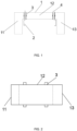
- FIG. 1 is a schematic structural view of a battery box 1
- FIG. 2 is a schematic top view of a battery box
- FIG. 3 is a stereoscopic schematic view of a battery box.
- the cross section of the battery box 1 is in the shape of inverted concave font
- the battery box 1 is mounted by the locking device on the longitudinal beam 2 of the carrier vehicle in a way of saddle
- the battery box 1 includes a battery and a battery frame.
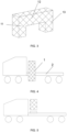
- FIG. 4 is a schematic view of a battery box 1 located in a position of the carrier vehicle according to some embodiments of the present application.
- the battery box 1 adopts a concave font mechanism.
- the middle part of the concave font mechanism is connected with the top end of the longitudinal beam 2 and two sides of the mechanism are respectively connected with two sides of the longitudinal beam 2.
- this configuration may effectively decrease the center of gravity of the battery box 1 and improve the stability of the battery box 1.
- the battery box there is one or more the battery box, which can be set according to the demand.
- the battery box 1 whose cross section is in a shape of inverted concave font is composed of two inverted L-shape sub-boxes, which are of mirror symmetry and separated type.
- the battery in the battery box 1 is an integrated concave font battery
- the battery frame is also concave font and the concave font battery is provided in the inverted concave font frame.
- the battery is an integrated inverted concave font battery
- the battery frame is composed of two separate L-shaped frames.
- the hoisting carrier vehicle of replaceable batteries further includes an inclining prevention device fixed on the carrier vehicle and in tight abutment with a side of the battery frame close to a cab.
- the inclining prevention device includes a support portion, and an end of the inclining prevention device is fixedly connected to the carrier vehicle and another end of the inclining prevention device is abutted against the battery frame.
- the support portion includes at least one inclined support rod and the support rods are configured to uniformly support every area of the battery box 1, which may make the force points evenly distributed for better supporting.
- the end of the support rod connected to the battery box 1 may be set as a support plane, and the support plane is abutted against the battery box frame.
- the support plane not only can prevent inclining, but also ensure that the battery box 1 may be replaced directly after unlocking the locking device, which needs no additional steps to disconnect the anti-inclining slope and the battery frame.
- the support portion may be a right-angled triangular support block, one of the right-angled sides of the triangular support block is connected to the vehicle, and the other right-angled side of the triangular support block is connected to the battery frame.
- the support portion may not only be provided in both the forward and backward inclining directions of the battery frame, but also be provided in both the leftward and rightward inclining direction, which may prevent the battery box 1 from inclining when the vehicle is braking or accelerating and from inclining over when the vehicle is rolled over.
- the stability of the battery box 1 is ensured by avoiding the battery frame from falling in some directions, to improve the safety to a certain extent.
- the battery frame may be an integrated structure or a split structure which may be assembled to make the battery be mounted inside the battery frame.
- the battery frame may be a concave font frame.
- the battery frame further includes a first bracket 11, a second bracket 12 and a third bracket 13.
- the first bracket 11 is vertically provided on one end of the second bracket 12 and the third bracket 13 is vertically provided on another end of the second bracket 12, and the second bracket 12 is transversely and horizontally fixed on a top end of the longitudinal beam 2.
- the first bracket 11 and the third bracket 13 are provided on opposite sides of the vehicle longitudinal beam 2.
- the hoisting carrier vehicle of replaceable batteries further includes a locking device.
- the locking device includes a first locking portion 3 and a second locking portion 4.
- the first locking portion 3 is provided on an outer side of the second bracket 12.
- the second locking portion 4 is provided on the top end of the longitudinal beam 2.
- the second bracket 12 is fixed on the top end of the longitudinal beam by the first locking portion 3 fitting with the second locking portion 4.
- the first locking portion 3 includes a plurality of first locking members provided around the outer side of the second bracket 12.
- first locking members may be provided on the outer sides of the second bracket 12 of the concave font battery frame and each side is provided with two first locking members. It is implementable that the number of locking members may also be increased as required.
- the second locking portion 4 includes a plurality of second locking members provided in correspondence with the first locking members.
- the locking device further includes a fastener.
- the first locking member includes a locking through hole and the second locking member includes a locking post fit with the locking through hole.
- the locking post is configured to penetrate through the locking through hole to fit the fastener.
- the fastener may be a fixed nut and the locking post is provided with threads at the top of the nut to match the nut.
- the locking device further includes a fastener
- the first locking member includes a first locking through hole
- the second locking member includes a second locking through hole.
- the fastener is configured to sequentially penetrate through the first locking through hole and the second locking through hole to fit the second locking through hole.
- the second locking through hole is provided with internal threads and the fastener is a bolt with external threads.
- the first locking member includes a first locking body 31 and a locking assembly and the second locking member includes a second locking body 41.
- the locking assembly includes a driving rod 32, an ejecting steel pillar 34 and two locking steel pillars 33.
- the first locking body 31 is provided with a locking cavity fit with the locking assembly, both the ejecting steel pillar 34 and the two locking steel pillars 33 are provided inside the locking cavity, and the locking cavity is provided with a first opening and a second opening opposite to the first opening.
- the first locking body 31 is configured to extend inside the second locking body 41 and the driving rod 32 is configured to extend inside the locking cavity to control a position of the ejecting steel pillar 34.
- the driving rod 32 is configured to control the position of the ejecting steel pillar 34 to make the ejecting steel pillar 34 respectively eject the two locking steel pillars 33 out of the first opening and the second opening to abut against an inner wall of the second locking body 41 for locking; or the driving rod 32 is configured to control the position of the ejecting steel pillar 34 to make the two locking steel pillars 33 stay inside the second locking body 41, but not abut against the inner wall of the second locking body 42 for unlocking.
- the first locking body is provided with a guide section and the guide section is formed by the outer wall of the clamping section gradually shrinking inward.
- the locking device in those embodiments of the present application is simple and low cost.
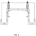
- FIG. 7 shows a schematic structural view of a battery box engaged with a mounting bracket.
- the mounting bracket is a concave font bracket.
- the mounting bracket includes a first mounting bracket 51, a second mounting bracket 52 and a third mounting bracket 53.
- the second mounting bracket 52 is fixed on the top end of the longitudinal beam 2.
- the first mounting bracket 51 is vertically provided on one end of the second mounting bracket 52 and the third mounting bracket 53 is vertically provided on another end of the second mounting bracket 52.
- the first mounting bracket 51 and the third mounting bracket 53 are provided on opposite sides of the vehicle longitudinal beam 2.
- the battery box 1 is connected with the second mounting bracket 52 through the locking device on the battery frame.
- the first bracket 11 and the third bracket 13 of the battery frame are respectively provided on the first mounting bracket 51 and the third mounting bracket 53.
- the first mounting bracket 51 is provided with a first fixing groove 54 and the third mounting bracket 53 is provided with a second fixing groove 55.
- the first bracket 11 of the battery frame is fixed on the first bracket 11 through the first fixing groove 54.
- the third bracket 13 of the battery frame is fixed on the third bracket 13 through the second fixing groove 55.
- the size of the two fixing grooves is suitable to just accommodate the two brackets of the battery frame.
- the fixing grooves may prevent the battery box 1 from inclining and increase the stability.
- the mounting bracket may include a first force-bearing section, and the first force-bearing section includes a first support piece and a second support piece. One end of the first support piece and one end of the second support piece are respectively connected to the two sides of the second mounting bracket 52.
- the rod section includes a first rod section and a second rod section. An end of the first rod section and an end of the second rod section are respectively connected with the other end of the first support piece and the other end of the second support piece. The other end of the first rod section and the other end of the second rod section are respectively connected with two opposite outer sides of the battery frame.
- the battery frame may also provided with a second force-bearing section which includes a third rod section and a fourth rod section.
- the third rod section and the fourth rod section are provided crosswise. An end of the third rod section and an end of the fourth rod section are both connected with the top end of the first bracket 11 of the battery frame. The other end of the third rod section extends out of the first bracket 11 to connect the other end of the first rod section.
- the third rod section is provided in a straight line.
- the other end of the fourth rod section extends out of the first bracket 11 to connect the other end of the second rod section.
- the fourth rod section is provided in a straight line.
- the rod sections in a line have a function for supporting and make the battery keep balance to prevent the battery from falling.
- the battery box 1 of the hoisting carrier vehicle of replaceable batteries provided in the application adopts a inverted concave font and the middle portion of the inverted concave font is connected with the longitudinal beam 2, which may effectively lower the center of gravity of the battery box 1.
- an inclining prevention device is provided to prevent the battery box 1 from inclining forward when braking, thereby to effectively increase the stability of the battery box 1.
- the battery box 1 may be replaced quickly through the quick locking and unlocking of the locking device.
Landscapes
- Engineering & Computer Science (AREA)
- Transportation (AREA)
- Mechanical Engineering (AREA)
- Power Engineering (AREA)
- Life Sciences & Earth Sciences (AREA)
- Sustainable Development (AREA)
- Sustainable Energy (AREA)
- Chemical & Material Sciences (AREA)
- Combustion & Propulsion (AREA)
- Battery Mounting, Suspending (AREA)
- Arrangement Or Mounting Of Propulsion Units For Vehicles (AREA)
Abstract
Description
- The present application relates to the technical field of battery replacement, and in particular, to a hoisting carrier vehicle of replaceable batteries.
- Energy saving, environmental protection and safety are always the main themes of automobile development, which are achieved by electrification, intelligence, networking and sharing. However, since the number of charging piles is small, the driving distance of current electric vehicles is short, which affects the promotion and application of electric vehicles at a certain extent.
- Some solutions in the prior art increase the number of charging piles to meet the charging demand, and some solutions adopt removable and replaceable power batteries. Since the former solutions spend too long time in charging, they are good technical solutions for passenger cars with short daily driving miles, but not applicable to heavy-duty vehicles such as commercial vehicles that require large capacity of power battery. The latter solutions are applicable to both passenger cars and commercial vehicles, but still suffers from a higher center of gravity of the power battery, an unreliable installation and uneasy replacement. For example, the patent of Shanghai Jiu Xing Energy Technology Co., Ltd. "Load truck with function of battery replacement and charging and power supply method" discloses the solutions of fixing the rectangular battery box on the vehicle. However, the battery box has the instability problem caused by high center of gravity; the patent "Hoisting container AGV transport vehicle of replaceable batteries" discloses that the battery box frame provided above the two battery sub-boxes is provided on the longitudinal beam through the positioning mechanism. However, the battery box structure and positioning structure are too complicated, costly and not stable enough to be installed.
- The application aims to solve the existing technical problem of a high center of gravity of the power battery, the unreliable installation and uneasy replacement.
- In order to achieve the above objective, the present application provides a hoisting carrier vehicle of replaceable batteries. The hoisting carrier vehicle of replaceable batteries includes a battery box whose cross section is in a shape of inverted concave font. The battery box is mounted by a locking device on the longitudinal beam of the carrier vehicle in a way of saddle. The battery box includes a battery and a battery frame.
- In some embodiments, the battery box whose cross section is in in the shape of the inverted concave font is composed of two inverted L-shape sub-boxes, which are of mirror symmetry and separated type.
- In some embodiments, the hoisting carrier vehicle of replaceable batteries further includes an inclining prevention device fixed on the carrier vehicle and in tight abutment with a side of the battery frame close to a cab.
- In some embodiments, the battery frame further includes a first bracket, a second bracket and a third bracket. The first bracket is vertically provided on one end of the second bracket and the third bracket is vertically provided on another end of the second bracket, and the second bracket is transversely and horizontally fixed on a top end of the longitudinal beam.
- In some embodiments, the locking device includes a first locking portion and a second locking portion. The first locking portion is provided on an outer side of the second bracket, the second locking portion is provided on the top end of the longitudinal beam, and the second bracket is fixed on the top end of the longitudinal beam by the first locking portion fitting with the second locking portion.
- In some embodiments, the first locking portion includes a plurality of first locking members provided around the outer side of the middle portion, and the second locking portion includes a plurality of second locking members provided in correspondence one-by-one with the first locking members.
- In some embodiments, the locking device further includes a fastener. The first locking member includes a locking through hole and the second locking member includes a locking post fit with the locking through hole, and the locking post is configured to penetrate through the locking through hole to fit the fastener; or
the first locking member includes a first locking through hole, the second locking member includes a second locking through hole, and the fastener is configured to sequentially penetrate through the first locking through hole and the second locking through hole to fit the second locking through hole. - In some embodiments, the first locking member includes a first locking body and a locking assembly and the second locking member includes a second locking body,
- the locking assembly includes a driving rod, an ejecting steel pillar and two locking steel pillars,
- the first locking body is provided with a locking cavity fit with the locking assembly, both the ejecting steel pillar and the two locking steel pillars are provided inside the locking cavity, and the locking cavity is provided with a first opening and a second opening opposite to the first opening,
- the first locking body is configured to extend inside the second locking body and the driving rod is configured to extend inside the locking cavity to control a position of the ejecting steel pillar, and
- the driving rod is configured to control the position of the ejecting steel pillar to make the ejecting steel pillar respectively eject the two locking steel pillars out of the first opening and the second opening to abut against an inner wall of the second locking body for locking; or
- the driving rod is configured to control the position of the ejecting steel pillar to make the two locking steel pillars stay inside the second locking body, but not abut against the inner wall of the second locking body for unlocking.
- In some embodiments, the inclining prevention device includes a support portion, and an end of the inclining prevention device is fixedly connected to the carrier vehicle and another end of the inclining prevention device is abutted against the battery frame.
- In some embodiments, the support portion includes at least one inclined support rod.
- By adopting the above-mentioned solutions, the application has the following beneficial effects:
The battery box of the hoisting carrier vehicle of replaceable batteries provided by the present application is in a shape of inverted concave font, and the middle portion of the inverted concave font is connected with the longitudinal beam, which may effectively lower the center of gravity of the battery box. Secondly, an inclining prevention device is provided to prevent the battery box from inclining forward when braking, to effectively increase the stability of the battery box. In addition, the battery box may be replaced quickly through the quick locking and unlocking of the locking device. - In order to more clearly illustrate the technical solutions in the embodiments of the present application, drawings in the embodiments will be briefly described below. Obviously, the drawings in the following description are only some embodiments of the present application. Other drawings can be obtained by those skilled in the art according to the structures shown in the drawings without creative work.
-
FIG. 1 is a schematic structural view of a battery box according to some embodiments of the present application. -
FIG. 2 is a schematic top view of a battery box according to some embodiments of the present application. -
FIG. 3 is a stereoscopic schematic view of a battery box according to some embodiments of the present application. -
FIG. 4 is a schematic view of a battery box located in a position of the carrier vehicle according to some embodiments of the present application. -
FIG. 5 is a schematic view of a battery box located in a position of the carrier vehicle according to the prior art. -
FIG. 6 is a schematic structural view of a locking device according to some embodiments of the present application. -
FIG. 7 is a schematic structural view of a mounting bracket according to some embodiments of the present application. -
FIG. 8 is a schematic structural view of a battery box engaged with a mounting bracket according to some embodiments of the present application. - The following are additional descriptions of the attached drawings.
- 1-battery box; 11-first bracket; 12-second bracket; 13-third bracket; 2-longitudinal beam; 3-first locking portion; 31-first locking body; 32-driving rod; 33-locking steel pillars; 34-ejecting steel pillar; 4-second locking portion; 41-second locking body; 51-first mounting bracket; 52-second mounting bracket; 53-third mounting bracket; 54-first fixing groove; 55-second fixing groove.
- The technical solutions of embodiments of the present application will be clearly and completely described with reference to the drawings of the present application. Obviously, the described embodiments are only some rather than all of the embodiments of the present application. Based on the embodiments of the present application, all other embodiments obtained by those skilled in the art without creative efforts shall fall within the scope of the present application.
- "one embodiment" or "an embodiment" herein refers to a specific feature, structure or characteristic that may be included in at least one implementation of the present application. In the description of the embodiment of the present application, it should be noted that the orientation or positional relationship indicated by the terms, such as up, down, left, right, front, rear, etc. are based on the drawings, which are only used to facilitate the description of this application and to simplify the description but not intended to indicate or imply that the device or element must in a particular orientation, or be constructed and operated in a particular orientation, which, therefore, should not be considered as limiting of the application.
- In addition, the descriptions related to "first", "second" and the like in the present application are merely for descriptive purposes, and should not be understood as indicating or implying their relative importance or implicitly indicating the number of technical features indicated. Therefore, the feature defined by "first" and "second" may explicitly or implicitly include at least one such feature. Further, the terms "first", "second", etc. are used to distinguish similar objects and need not be used to describe a particular order or sequence. It should be understood that the terms so used may be interchanged, where appropriate, so that the embodiments of the present application described herein can be implemented in an order other than those illustrated or described herein.
- The present application discloses a hoisting carrier vehicle of replaceable batteries including a
battery box 1. Referring toFIGS. 1-3 ,FIG. 1 is a schematic structural view of abattery box 1,FIG. 2 is a schematic top view of a battery box, andFIG. 3 is a stereoscopic schematic view of a battery box. As shown inFIGS. 1-3 , the cross section of thebattery box 1 is in the shape of inverted concave font, thebattery box 1 is mounted by the locking device on thelongitudinal beam 2 of the carrier vehicle in a way of saddle, and thebattery box 1 includes a battery and a battery frame. The way of saddle means that the battery box of inverted concave font is inverted on thelongitudinal beam 2, such that thelongitudinal beam 2 supports the concave section of the battery box. As shown inFIG. 4, FIG. 4 is a schematic view of abattery box 1 located in a position of the carrier vehicle according to some embodiments of the present application. Thebattery box 1 adopts a concave font mechanism. The middle part of the concave font mechanism is connected with the top end of thelongitudinal beam 2 and two sides of the mechanism are respectively connected with two sides of thelongitudinal beam 2. Compared with the square structure integrally provided on the vehicle in the prior art (as shown inFIG. 5 ), this configuration may effectively decrease the center of gravity of thebattery box 1 and improve the stability of thebattery box 1. - In some embodiments of the present application, there is one or more the battery box, which can be set according to the demand.
- In some embodiments of the present application, the
battery box 1 whose cross section is in a shape of inverted concave font is composed of two inverted L-shape sub-boxes, which are of mirror symmetry and separated type. In one implementable solution, the battery in thebattery box 1 is an integrated concave font battery, the battery frame is also concave font and the concave font battery is provided in the inverted concave font frame. In another implementable solution, the battery is an integrated inverted concave font battery, and the battery frame is composed of two separate L-shaped frames. - In some embodiments of the present application, the hoisting carrier vehicle of replaceable batteries further includes an inclining prevention device fixed on the carrier vehicle and in tight abutment with a side of the battery frame close to a cab.
- The inclining prevention device includes a support portion, and an end of the inclining prevention device is fixedly connected to the carrier vehicle and another end of the inclining prevention device is abutted against the battery frame.
- In one embodiment, the support portion includes at least one inclined support rod and the support rods are configured to uniformly support every area of the
battery box 1, which may make the force points evenly distributed for better supporting. - It can be implemented that the end of the support rod connected to the
battery box 1 may be set as a support plane, and the support plane is abutted against the battery box frame. The support plane not only can prevent inclining, but also ensure that thebattery box 1 may be replaced directly after unlocking the locking device, which needs no additional steps to disconnect the anti-inclining slope and the battery frame. - In another embodiment, the support portion may be a right-angled triangular support block, one of the right-angled sides of the triangular support block is connected to the vehicle, and the other right-angled side of the triangular support block is connected to the battery frame.
- In some embodiments of the present application, the support portion may not only be provided in both the forward and backward inclining directions of the battery frame, but also be provided in both the leftward and rightward inclining direction, which may prevent the
battery box 1 from inclining when the vehicle is braking or accelerating and from inclining over when the vehicle is rolled over. The stability of thebattery box 1 is ensured by avoiding the battery frame from falling in some directions, to improve the safety to a certain extent. - In some embodiments of the present application, the battery frame may be an integrated structure or a split structure which may be assembled to make the battery be mounted inside the battery frame.
- In some embodiments of the present application, the battery frame may be a concave font frame. Specifically, the battery frame further includes a
first bracket 11, asecond bracket 12 and athird bracket 13. - The
first bracket 11 is vertically provided on one end of thesecond bracket 12 and thethird bracket 13 is vertically provided on another end of thesecond bracket 12, and thesecond bracket 12 is transversely and horizontally fixed on a top end of thelongitudinal beam 2. Thefirst bracket 11 and thethird bracket 13 are provided on opposite sides of the vehiclelongitudinal beam 2. - In some embodiments of the present application, the hoisting carrier vehicle of replaceable batteries further includes a locking device.
- The locking device includes a
first locking portion 3 and asecond locking portion 4. - The
first locking portion 3 is provided on an outer side of thesecond bracket 12. Thesecond locking portion 4 is provided on the top end of thelongitudinal beam 2. Thesecond bracket 12 is fixed on the top end of the longitudinal beam by thefirst locking portion 3 fitting with thesecond locking portion 4. - In some embodiments of the present application, the
first locking portion 3 includes a plurality of first locking members provided around the outer side of thesecond bracket 12. For example, four first locking members may be provided on the outer sides of thesecond bracket 12 of the concave font battery frame and each side is provided with two first locking members. It is implementable that the number of locking members may also be increased as required. - The
second locking portion 4 includes a plurality of second locking members provided in correspondence with the first locking members. - In some embodiments of the present application, there are various options for setting the locking device. The following are some of them.
- In the first implementable solution, the locking device further includes a fastener. The first locking member includes a locking through hole and the second locking member includes a locking post fit with the locking through hole. The locking post is configured to penetrate through the locking through hole to fit the fastener. The fastener may be a fixed nut and the locking post is provided with threads at the top of the nut to match the nut.
- In the second implementable solution, the locking device further includes a fastener, the first locking member includes a first locking through hole and the second locking member includes a second locking through hole. The fastener is configured to sequentially penetrate through the first locking through hole and the second locking through hole to fit the second locking through hole. The second locking through hole is provided with internal threads and the fastener is a bolt with external threads.
- In the third implementable solution, as shown in
FIG. 6 , the first locking member includes afirst locking body 31 and a locking assembly and the second locking member includes asecond locking body 41. The locking assembly includes a drivingrod 32, an ejectingsteel pillar 34 and two lockingsteel pillars 33. Thefirst locking body 31 is provided with a locking cavity fit with the locking assembly, both the ejectingsteel pillar 34 and the two lockingsteel pillars 33 are provided inside the locking cavity, and the locking cavity is provided with a first opening and a second opening opposite to the first opening. Thefirst locking body 31 is configured to extend inside thesecond locking body 41 and the drivingrod 32 is configured to extend inside the locking cavity to control a position of the ejectingsteel pillar 34. The drivingrod 32 is configured to control the position of the ejectingsteel pillar 34 to make the ejectingsteel pillar 34 respectively eject the two lockingsteel pillars 33 out of the first opening and the second opening to abut against an inner wall of thesecond locking body 41 for locking; or the drivingrod 32 is configured to control the position of the ejectingsteel pillar 34 to make the two lockingsteel pillars 33 stay inside thesecond locking body 41, but not abut against the inner wall of the second locking body 42 for unlocking. - In some embodiments of the present application, the first locking body is provided with a guide section and the guide section is formed by the outer wall of the clamping section gradually shrinking inward. The locking device in those embodiments of the present application is simple and low cost.
- In some embodiments of the present application, additional mounting bracket may be included. As shown in
FIG. 7 , the mounting bracket is fixed to the top end of the vehiclelongitudinal beam 2, and the second locking members mentioned above may all be provided on the mounting bracket.FIG. 8 shows a schematic structural view of a battery box engaged with a mounting bracket. - In some implementable solutions, the mounting bracket is a concave font bracket. The mounting bracket includes a first mounting
bracket 51, asecond mounting bracket 52 and athird mounting bracket 53. Thesecond mounting bracket 52 is fixed on the top end of thelongitudinal beam 2. Thefirst mounting bracket 51 is vertically provided on one end of the second mountingbracket 52 and the third mountingbracket 53 is vertically provided on another end of the second mountingbracket 52. Thefirst mounting bracket 51 and the third mountingbracket 53 are provided on opposite sides of the vehiclelongitudinal beam 2. - The
battery box 1 is connected with the second mountingbracket 52 through the locking device on the battery frame. Thefirst bracket 11 and thethird bracket 13 of the battery frame are respectively provided on the first mountingbracket 51 and the third mountingbracket 53. - The
first mounting bracket 51 is provided with afirst fixing groove 54 and the third mountingbracket 53 is provided with asecond fixing groove 55. Thefirst bracket 11 of the battery frame is fixed on thefirst bracket 11 through the first fixinggroove 54. Thethird bracket 13 of the battery frame is fixed on thethird bracket 13 through thesecond fixing groove 55. The size of the two fixing grooves is suitable to just accommodate the two brackets of the battery frame. The fixing grooves may prevent thebattery box 1 from inclining and increase the stability. - The mounting bracket may include a first force-bearing section, and the first force-bearing section includes a first support piece and a second support piece. One end of the first support piece and one end of the second support piece are respectively connected to the two sides of the second mounting
bracket 52. - The rod section includes a first rod section and a second rod section. An end of the first rod section and an end of the second rod section are respectively connected with the other end of the first support piece and the other end of the second support piece. The other end of the first rod section and the other end of the second rod section are respectively connected with two opposite outer sides of the battery frame.
- The battery frame may also provided with a second force-bearing section which includes a third rod section and a fourth rod section. The third rod section and the fourth rod section are provided crosswise. An end of the third rod section and an end of the fourth rod section are both connected with the top end of the
first bracket 11 of the battery frame. The other end of the third rod section extends out of thefirst bracket 11 to connect the other end of the first rod section. The third rod section is provided in a straight line. The other end of the fourth rod section extends out of thefirst bracket 11 to connect the other end of the second rod section. The fourth rod section is provided in a straight line. The rod sections in a line have a function for supporting and make the battery keep balance to prevent the battery from falling. - The
battery box 1 of the hoisting carrier vehicle of replaceable batteries provided in the application adopts a inverted concave font and the middle portion of the inverted concave font is connected with thelongitudinal beam 2, which may effectively lower the center of gravity of thebattery box 1. Secondly, an inclining prevention device is provided to prevent thebattery box 1 from inclining forward when braking, thereby to effectively increase the stability of thebattery box 1. In addition, thebattery box 1 may be replaced quickly through the quick locking and unlocking of the locking device. - Finally, it should be noted that the above are only some embodiments of the present application, and do not limit the scope of the present application thereto. Under the concept of the present application, equivalent structural transformations made according to the description and drawings of the present application, or direct/indirect application in other related technical fields are included in the scope of the present application.
Claims (10)
- A hoisting carrier vehicle of replaceable batteries, characterizing by comprising:a battery box (1) whose cross section is in a shape of inverted concave font, wherein the battery box comprises a battery and a battery frame;a locking device; anda longitudinal beam (2);wherein the battery box (1) is mounted by the locking device on the longitudinal beam of the carrier vehicle in a way of saddle.
- The hoisting carrier vehicle of claim 1, further comprising:
an inclining prevention device fixed on the carrier vehicle and in tight abutment with a side of the battery frame close to a cab. - The hoisting carrier vehicle of claim 1, wherein the battery box (1) whose cross section is in in the shape of the inverted concave font is composed of two inverted L-shape sub-boxes, which are of mirror symmetry and separated type.
- The hoisting carrier vehicle of claim 1, wherein the battery frame further comprises a first bracket (11), a second bracket (12) and a third bracket (13),the first bracket (11) is vertically provided on one end of the second bracket (12) and the third bracket (13) is vertically provided on another end of the second bracket (12), andthe second bracket (12) is horizontally fixed on a top end of the longitudinal beam (2).
- The hoisting carrier vehicle of claim 4, wherein the locking device comprises a first locking portion (3) and a second locking portion (4),the first locking portion (3) is provided on an outer side of the second bracket (12),the second locking portion (4) is provided on the top end of the longitudinal beam (2), andthe second bracket (12) is fixed on the top end of the longitudinal beam (2) by the first locking portion (3) fitting with the second locking portion (4).
- The hoisting carrier vehicle of claim 5, wherein the first locking portion (3) comprises a plurality of first locking members provided around the outer side of a middle portion, and
the second locking portion (4) comprises a plurality of second locking members in correspondence one-by-one with the first locking members. - The hoisting carrier vehicle of claim 6, wherein the locking device further comprises a fastener,the first locking member comprises a locking through hole, the second locking member comprises a locking post fit with the locking through hole, and the locking post is configured to penetrate through the locking through hole to fit with the fastener; orthe first locking member comprises a first locking through hole, the second locking member comprises a second locking through hole, and the fastener is configured to penetrate through the first locking through hole and the second locking through hole to fit the second locking through hole.
- The hoisting carrier vehicle of claim 6, wherein the first locking member comprises a first locking body and a locking assembly and the second locking member comprises a second locking body,the locking assembly comprises a driving rod, an ejecting steel pillar and two locking steel pillars,the first locking body is provided with a locking cavity fit with the locking assembly, both the ejecting steel pillar and the two locking steel pillars are provided inside the locking cavity, and the locking cavity is provided with a first opening and a second opening opposite to the first opening,the first locking body is configured to extend inside the second locking body and the driving rod is configured to extend inside the locking cavity to control a position of the ejecting steel pillar, andthe driving rod is configured to control the position of the ejecting steel pillar to make the ejecting steel pillar respectively eject the two locking steel pillars out of the first opening and the second opening to abut against an inner wall of the second locking body for locking; orthe driving portion is configured to control the position of the ejecting steel pillar to make the two locking steel pillars stay inside the second locking body for unlocking.
- The hoisting carrier vehicle of claim 3, wherein the inclining prevention device comprises a support portion, and
an end of the inclining prevention device is fixedly connected to the vehicle and another end of the inclining prevention device is abutted against the battery frame. - The hoisting carrier vehicle of claim 9, wherein the support portion comprises at least one inclined support rod.
Applications Claiming Priority (2)
| Application Number | Priority Date | Filing Date | Title |
|---|---|---|---|
| CN202011246789.0A CN112477573A (en) | 2020-11-10 | 2020-11-10 | Hoisting battery-replacing type carrying vehicle |
| PCT/CN2020/139408 WO2022099880A1 (en) | 2020-11-10 | 2020-12-25 | Hoisting battery-replacing type carrier vehicle |
Publications (4)
| Publication Number | Publication Date |
|---|---|
| EP4227130A1 true EP4227130A1 (en) | 2023-08-16 |
| EP4227130A4 EP4227130A4 (en) | 2024-10-30 |
| EP4227130B1 EP4227130B1 (en) | 2026-03-11 |
| EP4227130C0 EP4227130C0 (en) | 2026-03-11 |
Family
ID=74929743
Family Applications (1)
| Application Number | Title | Priority Date | Filing Date |
|---|---|---|---|
| EP20961433.8A Active EP4227130B1 (en) | 2020-11-10 | 2020-12-25 | Hoisting battery-replacing type carrier vehicle |
Country Status (6)
| Country | Link |
|---|---|
| US (1) | US12434593B2 (en) |
| EP (1) | EP4227130B1 (en) |
| JP (1) | JP7624526B2 (en) |
| KR (1) | KR102995962B1 (en) |
| CN (1) | CN112477573A (en) |
| WO (1) | WO2022099880A1 (en) |
Cited By (1)
| Publication number | Priority date | Publication date | Assignee | Title |
|---|---|---|---|---|
| TWI914979B (en) | 2024-08-23 | 2026-02-11 | 鴻海精密工業股份有限公司 | Connection device for battery pack |
Families Citing this family (9)
| Publication number | Priority date | Publication date | Assignee | Title |
|---|---|---|---|---|
| CN112277723B (en) * | 2020-11-30 | 2022-06-24 | 浙江吉利控股集团有限公司 | Battery replacement assembly of vehicle and vehicle |
| CN113611974A (en) * | 2021-08-24 | 2021-11-05 | 深圳精智机器有限公司 | Combined battery equipment and new energy vehicle |
| CN119189785B (en) * | 2021-11-30 | 2025-11-25 | 奥动新能源股份有限公司 | Mounting brackets, mounting devices, battery swapping packs, and electric vehicles |
| WO2023182979A1 (en) * | 2022-03-22 | 2023-09-28 | Coulomb Solutions, Inc. | Electric vehicle battery module |
| WO2023182980A1 (en) * | 2022-03-22 | 2023-09-28 | Coulomb Solutions, Inc. | Modular chassis for an electric vehicle |
| CN117199657A (en) * | 2022-05-31 | 2023-12-08 | 奥动新能源汽车科技有限公司 | A battery pack and electric vehicle |
| CN116409130A (en) * | 2022-07-15 | 2023-07-11 | 奥动新能源汽车科技有限公司 | battery replacement vehicle |
| CN116749825B (en) * | 2023-08-18 | 2023-11-10 | 北京玖行智研交通科技有限公司 | Saddle type battery box bottom bracket for new energy automobile |
| CN117549732B (en) * | 2023-11-13 | 2024-06-28 | 济南豪瑞通专用汽车有限公司 | Small-size sanitation car of pure electric |
Family Cites Families (25)
| Publication number | Priority date | Publication date | Assignee | Title |
|---|---|---|---|---|
| JPS5039528Y2 (en) * | 1971-08-13 | 1975-11-13 | ||
| DE20209159U1 (en) * | 2002-06-12 | 2002-08-29 | Eduard Wille GmbH & Co, 42349 Wuppertal | Quick lock for extensions of plug-in tools |
| JP2013006568A (en) * | 2011-06-27 | 2013-01-10 | Toyota Industries Corp | Transfer device |
| ES2373905B1 (en) * | 2011-11-25 | 2012-09-07 | Urban Resilience, S.L. | Installation for parking and recharging of electric vehicles. |
| DE102012108769A1 (en) * | 2012-09-18 | 2014-03-20 | Gottwald Port Technology Gmbh | Battery Electric Tractor Trailer for ISO Container Transport |
| CN105644639A (en) * | 2015-12-28 | 2016-06-08 | 航天重型工程装备有限公司 | Mining electric trackless carrier vehicle |
| CN205853862U (en) * | 2016-07-15 | 2017-01-04 | 中信国安盟固利动力科技有限公司 | A kind of lithium battery device for fixing boxes |
| CN206171159U (en) * | 2016-08-31 | 2017-05-17 | 上海蔚来汽车有限公司 | Battery box locking device and including this battery box locking device's battery box |
| CN207842904U (en) * | 2017-12-12 | 2018-09-11 | 蔚来汽车有限公司 | Fastener locking and unlocking mechanism and system and vehicle battery replacement operating platform |
| CN207790296U (en) * | 2018-01-04 | 2018-08-31 | 蔚来汽车有限公司 | Battery Pack Locking Mechanism |
| EP3840972B1 (en) * | 2018-08-24 | 2024-09-11 | Hexagon Purus North America Holdings Inc. | Battery system for heavy duty vehicles |
| WO2020074105A1 (en) * | 2018-10-12 | 2020-04-16 | Volvo Truck Corporation | A battery pack arrangement for a vehicle |
| CN209008372U (en) * | 2018-10-22 | 2019-06-21 | 大运汽车股份有限公司 | Heavy hauler power battery bracket |
| US11040610B2 (en) * | 2019-04-19 | 2021-06-22 | Hexagon Purus North America Holdings Inc. | Electric powertrain system for heavy duty vehicles |
| CN210941319U (en) * | 2019-06-11 | 2020-07-07 | 浙江吉智新能源汽车科技有限公司 | A quick locking mechanism, installation device and automobile |
| CN210325889U (en) * | 2019-06-11 | 2020-04-14 | 浙江吉智新能源汽车科技有限公司 | Locking device with limiting mechanism |
| CN110614911A (en) * | 2019-10-22 | 2019-12-27 | 长春致远新能源设备有限责任公司 | Guide positioning connection structure for cylindrical and groove composite power battery bracket |
| SE543973C2 (en) * | 2019-11-06 | 2021-10-12 | Scania Cv Ab | A battery box arrangement |
| CN213383896U (en) * | 2019-12-25 | 2021-06-08 | 上海玖行能源科技有限公司 | Trucks with battery swap and charging capabilities |
| CN111002844B (en) * | 2019-12-25 | 2024-04-09 | 上海玖行能源科技有限公司 | Load-carrying truck with battery replacement and charging functions and power supply method thereof |
| CN211685401U (en) * | 2020-01-17 | 2020-10-16 | 上海玖行能源科技有限公司 | Top-mounted battery-swappable container AGV transport vehicle |
| CN111137372A (en) * | 2020-01-17 | 2020-05-12 | 上海玖行能源科技有限公司 | Top-mounted battery-swappable container AGV transport vehicle |
| EP3925808A1 (en) * | 2020-06-16 | 2021-12-22 | Volvo Truck Corporation | Chassis arrangement for electrified heavy vehicle and electrified heavy vehicle |
| CN111845437B (en) * | 2020-07-20 | 2025-04-29 | 浙江吉智新能源汽车科技有限公司 | A locking device for battery replacement and a vehicle using the same |
| EP3981631B1 (en) * | 2020-10-12 | 2024-12-18 | Volvo Truck Corporation | A battery assembly |
-
2020
- 2020-11-10 CN CN202011246789.0A patent/CN112477573A/en active Pending
- 2020-12-25 WO PCT/CN2020/139408 patent/WO2022099880A1/en not_active Ceased
- 2020-12-25 KR KR1020237018309A patent/KR102995962B1/en active Active
- 2020-12-25 JP JP2023550340A patent/JP7624526B2/en active Active
- 2020-12-25 EP EP20961433.8A patent/EP4227130B1/en active Active
-
2023
- 2023-05-10 US US18/314,998 patent/US12434593B2/en active Active
Cited By (1)
| Publication number | Priority date | Publication date | Assignee | Title |
|---|---|---|---|---|
| TWI914979B (en) | 2024-08-23 | 2026-02-11 | 鴻海精密工業股份有限公司 | Connection device for battery pack |
Also Published As
| Publication number | Publication date |
|---|---|
| CN112477573A (en) | 2021-03-12 |
| EP4227130B1 (en) | 2026-03-11 |
| EP4227130A4 (en) | 2024-10-30 |
| US12434593B2 (en) | 2025-10-07 |
| KR20230121731A (en) | 2023-08-21 |
| WO2022099880A1 (en) | 2022-05-19 |
| JP2023546998A (en) | 2023-11-08 |
| US20230302952A1 (en) | 2023-09-28 |
| KR102995962B1 (en) | 2026-07-27 |
| JP7624526B2 (en) | 2025-01-30 |
| EP4227130C0 (en) | 2026-03-11 |
Similar Documents
| Publication | Publication Date | Title |
|---|---|---|
| US12434593B2 (en) | Hoisting carrier vehicle of replaceable batteries | |
| CN217227278U (en) | Chassis battery-replacing type electric heavy truck | |
| US12202542B2 (en) | Chassis assembly for a vehicle | |
| CN219544890U (en) | Frame of electric light truck | |
| CN115366646B (en) | Frame assembly, vehicle, power exchange station and power exchange method | |
| CN218085722U (en) | Frame assembly and vehicle | |
| CN217956030U (en) | Split type battery box, power battery, chassis and vehicle | |
| US20240123807A1 (en) | Structural assembly and vehicle having structural assembly | |
| CN217892496U (en) | Lateral connecting mechanism and vehicle | |
| CN115284862A (en) | Locking mechanism and vehicle | |
| US20240010080A1 (en) | Fuel cell vehicle | |
| CN217892497U (en) | Frame subassembly, vehicle and trade power station | |
| CN224060835U (en) | Chassis of vehicle and vehicle | |
| US12233695B1 (en) | Electric vehicle having motor shield | |
| US20240140530A1 (en) | Structural assembly for vehicle | |
| RU2819191C2 (en) | Hoisting truck with replaceable batteries | |
| CN218300074U (en) | Locking mechanism and vehicle | |
| CN223972453U (en) | Battery and vehicle | |
| CN218513598U (en) | Battery frame, battery package and vehicle | |
| CN112277723B (en) | Battery replacement assembly of vehicle and vehicle | |
| CN214165126U (en) | A quick-change frame | |
| KR20230051763A (en) | Front end structure for a motor vehicle with a crash structure arranged behind a cooling module | |
| CN115332708A (en) | Locking mechanism and vehicle | |
| CN218967016U (en) | Truck chassis | |
| CN219770000U (en) | Vehicle girder assembly and electric automobile |
Legal Events
| Date | Code | Title | Description |
|---|---|---|---|
| STAA | Information on the status of an ep patent application or granted ep patent |
Free format text: STATUS: THE INTERNATIONAL PUBLICATION HAS BEEN MADE |
|
| PUAI | Public reference made under article 153(3) epc to a published international application that has entered the european phase |
Free format text: ORIGINAL CODE: 0009012 |
|
| STAA | Information on the status of an ep patent application or granted ep patent |
Free format text: STATUS: REQUEST FOR EXAMINATION WAS MADE |
|
| 17P | Request for examination filed |
Effective date: 20230510 |
|
| AK | Designated contracting states |
Kind code of ref document: A1 Designated state(s): AL AT BE BG CH CY CZ DE DK EE ES FI FR GB GR HR HU IE IS IT LI LT LU LV MC MK MT NL NO PL PT RO RS SE SI SK SM TR |
|
| DAV | Request for validation of the european patent (deleted) | ||
| DAX | Request for extension of the european patent (deleted) | ||
| A4 | Supplementary search report drawn up and despatched |
Effective date: 20241002 |
|
| RIC1 | Information provided on ipc code assigned before grant |
Ipc: B60L 50/64 20190101ALN20240926BHEP Ipc: B60L 50/60 20190101ALN20240926BHEP Ipc: B60L 53/80 20190101ALI20240926BHEP Ipc: B60K 1/04 20190101AFI20240926BHEP |
|
| GRAP | Despatch of communication of intention to grant a patent |
Free format text: ORIGINAL CODE: EPIDOSNIGR1 |
|
| STAA | Information on the status of an ep patent application or granted ep patent |
Free format text: STATUS: GRANT OF PATENT IS INTENDED |
|
| RIC1 | Information provided on ipc code assigned before grant |
Ipc: B60K 1/04 20190101AFI20251119BHEP Ipc: B60L 53/80 20190101ALI20251119BHEP Ipc: B60L 50/60 20190101ALN20251119BHEP Ipc: B60L 50/64 20190101ALN20251119BHEP |
|
| RIC1 | Information provided on ipc code assigned before grant |
Ipc: B60K 1/04 20190101AFI20251203BHEP Ipc: B60L 53/80 20190101ALI20251203BHEP Ipc: B60L 50/60 20190101ALN20251203BHEP Ipc: B60L 50/64 20190101ALN20251203BHEP |
|
| INTG | Intention to grant announced |
Effective date: 20251215 |
|
| RAP3 | Party data changed (applicant data changed or rights of an application transferred) |
Owner name: ZHEJIANG GEELY HOLDING GROUP CO., LTD. Owner name: ZHEJIANG GEELY FARIZON NEW ENERGY COMMERCIALVEHICLE GROUP CO., LTD. |
|
| GRAS | Grant fee paid |
Free format text: ORIGINAL CODE: EPIDOSNIGR3 |
|
| GRAA | (expected) grant |
Free format text: ORIGINAL CODE: 0009210 |
|
| STAA | Information on the status of an ep patent application or granted ep patent |
Free format text: STATUS: THE PATENT HAS BEEN GRANTED |
|
| AK | Designated contracting states |
Kind code of ref document: B1 Designated state(s): AL AT BE BG CH CY CZ DE DK EE ES FI FR GB GR HR HU IE IS IT LI LT LU LV MC MK MT NL NO PL PT RO RS SE SI SK SM TR |
|
| REG | Reference to a national code |
Ref country code: CH Ref legal event code: F10 Free format text: ST27 STATUS EVENT CODE: U-0-0-F10-F00 (AS PROVIDED BY THE NATIONAL OFFICE) Effective date: 20260311 Ref country code: GB Ref legal event code: FG4D |
|
| REG | Reference to a national code |
Ref country code: DE Ref legal event code: R096 Ref document number: 602020068658 Country of ref document: DE |
|
| REG | Reference to a national code |
Ref country code: IE Ref legal event code: FG4D |
|
| U01 | Request for unitary effect filed |
Effective date: 20260312 |
|
| U07 | Unitary effect registered |
Designated state(s): AT BE BG DE DK EE FI FR IT LT LU LV MT NL PT RO SE SI Effective date: 20260317 |
|
| PG25 | Lapsed in a contracting state [announced via postgrant information from national office to epo] |
Ref country code: RS Free format text: LAPSE BECAUSE OF FAILURE TO SUBMIT A TRANSLATION OF THE DESCRIPTION OR TO PAY THE FEE WITHIN THE PRESCRIBED TIME-LIMIT Effective date: 20260611 |
|
| PG25 | Lapsed in a contracting state [announced via postgrant information from national office to epo] |
Ref country code: ES Free format text: LAPSE BECAUSE OF FAILURE TO SUBMIT A TRANSLATION OF THE DESCRIPTION OR TO PAY THE FEE WITHIN THE PRESCRIBED TIME-LIMIT Effective date: 20260311 |
|
| PG25 | Lapsed in a contracting state [announced via postgrant information from national office to epo] |
Ref country code: GR Free format text: LAPSE BECAUSE OF FAILURE TO SUBMIT A TRANSLATION OF THE DESCRIPTION OR TO PAY THE FEE WITHIN THE PRESCRIBED TIME-LIMIT Effective date: 20260612 |
|
| PG25 | Lapsed in a contracting state [announced via postgrant information from national office to epo] |
Ref country code: NO Free format text: LAPSE BECAUSE OF FAILURE TO SUBMIT A TRANSLATION OF THE DESCRIPTION OR TO PAY THE FEE WITHIN THE PRESCRIBED TIME-LIMIT Effective date: 20260611 |
|
| PG25 | Lapsed in a contracting state [announced via postgrant information from national office to epo] |
Ref country code: HR Free format text: LAPSE BECAUSE OF FAILURE TO SUBMIT A TRANSLATION OF THE DESCRIPTION OR TO PAY THE FEE WITHIN THE PRESCRIBED TIME-LIMIT Effective date: 20260311 |