EP4227056A1 - Die plate cover, die head, extruder, and method for manufacturing resin pellet - Google Patents
Die plate cover, die head, extruder, and method for manufacturing resin pellet Download PDFInfo
- Publication number
- EP4227056A1 EP4227056A1 EP21891401.8A EP21891401A EP4227056A1 EP 4227056 A1 EP4227056 A1 EP 4227056A1 EP 21891401 A EP21891401 A EP 21891401A EP 4227056 A1 EP4227056 A1 EP 4227056A1
- Authority
- EP
- European Patent Office
- Prior art keywords
- die plate
- die
- plate cover
- internal space
- molten resin
- Prior art date
- Legal status (The legal status is an assumption and is not a legal conclusion. Google has not performed a legal analysis and makes no representation as to the accuracy of the status listed.)
- Pending
Links
Images




Classifications
-
- B—PERFORMING OPERATIONS; TRANSPORTING
- B29—WORKING OF PLASTICS; WORKING OF SUBSTANCES IN A PLASTIC STATE IN GENERAL
- B29C—SHAPING OR JOINING OF PLASTICS; SHAPING OF MATERIAL IN A PLASTIC STATE, NOT OTHERWISE PROVIDED FOR; AFTER-TREATMENT OF THE SHAPED PRODUCTS, e.g. REPAIRING
- B29C48/00—Extrusion moulding, i.e. expressing the moulding material through a die or nozzle which imparts the desired form; Apparatus therefor
- B29C48/25—Component parts, details or accessories; Auxiliary operations
- B29C48/30—Extrusion nozzles or dies
- B29C48/345—Extrusion nozzles comprising two or more adjacently arranged ports, for simultaneously extruding multiple strands, e.g. for pelletising
-
- B—PERFORMING OPERATIONS; TRANSPORTING
- B29—WORKING OF PLASTICS; WORKING OF SUBSTANCES IN A PLASTIC STATE IN GENERAL
- B29B—PREPARATION OR PRETREATMENT OF THE MATERIAL TO BE SHAPED; MAKING GRANULES OR PREFORMS; RECOVERY OF PLASTICS OR OTHER CONSTITUENTS OF WASTE MATERIAL CONTAINING PLASTICS
- B29B7/00—Mixing; Kneading
- B29B7/80—Component parts, details or accessories; Auxiliary operations
- B29B7/82—Heating or cooling
- B29B7/823—Temperature control
-
- B—PERFORMING OPERATIONS; TRANSPORTING
- B29—WORKING OF PLASTICS; WORKING OF SUBSTANCES IN A PLASTIC STATE IN GENERAL
- B29B—PREPARATION OR PRETREATMENT OF THE MATERIAL TO BE SHAPED; MAKING GRANULES OR PREFORMS; RECOVERY OF PLASTICS OR OTHER CONSTITUENTS OF WASTE MATERIAL CONTAINING PLASTICS
- B29B7/00—Mixing; Kneading
- B29B7/30—Mixing; Kneading continuous, with mechanical mixing or kneading devices
- B29B7/58—Component parts, details or accessories; Auxiliary operations
- B29B7/582—Component parts, details or accessories; Auxiliary operations for discharging, e.g. doors
-
- B—PERFORMING OPERATIONS; TRANSPORTING
- B29—WORKING OF PLASTICS; WORKING OF SUBSTANCES IN A PLASTIC STATE IN GENERAL
- B29B—PREPARATION OR PRETREATMENT OF THE MATERIAL TO BE SHAPED; MAKING GRANULES OR PREFORMS; RECOVERY OF PLASTICS OR OTHER CONSTITUENTS OF WASTE MATERIAL CONTAINING PLASTICS
- B29B7/00—Mixing; Kneading
- B29B7/30—Mixing; Kneading continuous, with mechanical mixing or kneading devices
- B29B7/58—Component parts, details or accessories; Auxiliary operations
- B29B7/72—Measuring, controlling or regulating
-
- B—PERFORMING OPERATIONS; TRANSPORTING
- B29—WORKING OF PLASTICS; WORKING OF SUBSTANCES IN A PLASTIC STATE IN GENERAL
- B29B—PREPARATION OR PRETREATMENT OF THE MATERIAL TO BE SHAPED; MAKING GRANULES OR PREFORMS; RECOVERY OF PLASTICS OR OTHER CONSTITUENTS OF WASTE MATERIAL CONTAINING PLASTICS
- B29B7/00—Mixing; Kneading
- B29B7/74—Mixing; Kneading using other mixers or combinations of mixers, e.g. of dissimilar mixers ; Plant
- B29B7/7476—Systems, i.e. flow charts or diagrams; Plants
- B29B7/748—Plants
-
- B—PERFORMING OPERATIONS; TRANSPORTING
- B29—WORKING OF PLASTICS; WORKING OF SUBSTANCES IN A PLASTIC STATE IN GENERAL
- B29B—PREPARATION OR PRETREATMENT OF THE MATERIAL TO BE SHAPED; MAKING GRANULES OR PREFORMS; RECOVERY OF PLASTICS OR OTHER CONSTITUENTS OF WASTE MATERIAL CONTAINING PLASTICS
- B29B7/00—Mixing; Kneading
- B29B7/80—Component parts, details or accessories; Auxiliary operations
- B29B7/82—Heating or cooling
- B29B7/826—Apparatus therefor
-
- B—PERFORMING OPERATIONS; TRANSPORTING
- B29—WORKING OF PLASTICS; WORKING OF SUBSTANCES IN A PLASTIC STATE IN GENERAL
- B29B—PREPARATION OR PRETREATMENT OF THE MATERIAL TO BE SHAPED; MAKING GRANULES OR PREFORMS; RECOVERY OF PLASTICS OR OTHER CONSTITUENTS OF WASTE MATERIAL CONTAINING PLASTICS
- B29B7/00—Mixing; Kneading
- B29B7/80—Component parts, details or accessories; Auxiliary operations
- B29B7/86—Component parts, details or accessories; Auxiliary operations for working at sub- or superatmospheric pressure
-
- B—PERFORMING OPERATIONS; TRANSPORTING
- B29—WORKING OF PLASTICS; WORKING OF SUBSTANCES IN A PLASTIC STATE IN GENERAL
- B29B—PREPARATION OR PRETREATMENT OF THE MATERIAL TO BE SHAPED; MAKING GRANULES OR PREFORMS; RECOVERY OF PLASTICS OR OTHER CONSTITUENTS OF WASTE MATERIAL CONTAINING PLASTICS
- B29B9/00—Making granules
- B29B9/02—Making granules by dividing preformed material
- B29B9/06—Making granules by dividing preformed material in the form of filamentary material, e.g. combined with extrusion
-
- B—PERFORMING OPERATIONS; TRANSPORTING
- B29—WORKING OF PLASTICS; WORKING OF SUBSTANCES IN A PLASTIC STATE IN GENERAL
- B29B—PREPARATION OR PRETREATMENT OF THE MATERIAL TO BE SHAPED; MAKING GRANULES OR PREFORMS; RECOVERY OF PLASTICS OR OTHER CONSTITUENTS OF WASTE MATERIAL CONTAINING PLASTICS
- B29B9/00—Making granules
- B29B9/02—Making granules by dividing preformed material
- B29B9/06—Making granules by dividing preformed material in the form of filamentary material, e.g. combined with extrusion
- B29B9/065—Making granules by dividing preformed material in the form of filamentary material, e.g. combined with extrusion under-water, e.g. underwater pelletizers
-
- B—PERFORMING OPERATIONS; TRANSPORTING
- B29—WORKING OF PLASTICS; WORKING OF SUBSTANCES IN A PLASTIC STATE IN GENERAL
- B29C—SHAPING OR JOINING OF PLASTICS; SHAPING OF MATERIAL IN A PLASTIC STATE, NOT OTHERWISE PROVIDED FOR; AFTER-TREATMENT OF THE SHAPED PRODUCTS, e.g. REPAIRING
- B29C48/00—Extrusion moulding, i.e. expressing the moulding material through a die or nozzle which imparts the desired form; Apparatus therefor
- B29C48/001—Combinations of extrusion moulding with other shaping operations
- B29C48/0022—Combinations of extrusion moulding with other shaping operations combined with cutting
-
- B—PERFORMING OPERATIONS; TRANSPORTING
- B29—WORKING OF PLASTICS; WORKING OF SUBSTANCES IN A PLASTIC STATE IN GENERAL
- B29C—SHAPING OR JOINING OF PLASTICS; SHAPING OF MATERIAL IN A PLASTIC STATE, NOT OTHERWISE PROVIDED FOR; AFTER-TREATMENT OF THE SHAPED PRODUCTS, e.g. REPAIRING
- B29C48/00—Extrusion moulding, i.e. expressing the moulding material through a die or nozzle which imparts the desired form; Apparatus therefor
- B29C48/03—Extrusion moulding, i.e. expressing the moulding material through a die or nozzle which imparts the desired form; Apparatus therefor characterised by the shape of the extruded material at extrusion
- B29C48/05—Filamentary, e.g. strands
-
- B—PERFORMING OPERATIONS; TRANSPORTING
- B29—WORKING OF PLASTICS; WORKING OF SUBSTANCES IN A PLASTIC STATE IN GENERAL
- B29C—SHAPING OR JOINING OF PLASTICS; SHAPING OF MATERIAL IN A PLASTIC STATE, NOT OTHERWISE PROVIDED FOR; AFTER-TREATMENT OF THE SHAPED PRODUCTS, e.g. REPAIRING
- B29C48/00—Extrusion moulding, i.e. expressing the moulding material through a die or nozzle which imparts the desired form; Apparatus therefor
- B29C48/25—Component parts, details or accessories; Auxiliary operations
- B29C48/256—Exchangeable extruder parts
- B29C48/2566—Die parts
-
- B—PERFORMING OPERATIONS; TRANSPORTING
- B29—WORKING OF PLASTICS; WORKING OF SUBSTANCES IN A PLASTIC STATE IN GENERAL
- B29C—SHAPING OR JOINING OF PLASTICS; SHAPING OF MATERIAL IN A PLASTIC STATE, NOT OTHERWISE PROVIDED FOR; AFTER-TREATMENT OF THE SHAPED PRODUCTS, e.g. REPAIRING
- B29C48/00—Extrusion moulding, i.e. expressing the moulding material through a die or nozzle which imparts the desired form; Apparatus therefor
- B29C48/25—Component parts, details or accessories; Auxiliary operations
- B29C48/30—Extrusion nozzles or dies
- B29C48/3001—Extrusion nozzles or dies characterised by the material or their manufacturing process
-
- B—PERFORMING OPERATIONS; TRANSPORTING
- B29—WORKING OF PLASTICS; WORKING OF SUBSTANCES IN A PLASTIC STATE IN GENERAL
- B29B—PREPARATION OR PRETREATMENT OF THE MATERIAL TO BE SHAPED; MAKING GRANULES OR PREFORMS; RECOVERY OF PLASTICS OR OTHER CONSTITUENTS OF WASTE MATERIAL CONTAINING PLASTICS
- B29B7/00—Mixing; Kneading
- B29B7/30—Mixing; Kneading continuous, with mechanical mixing or kneading devices
- B29B7/34—Mixing; Kneading continuous, with mechanical mixing or kneading devices with movable mixing or kneading devices
- B29B7/38—Mixing; Kneading continuous, with mechanical mixing or kneading devices with movable mixing or kneading devices rotary
- B29B7/46—Mixing; Kneading continuous, with mechanical mixing or kneading devices with movable mixing or kneading devices rotary with more than one shaft
- B29B7/48—Mixing; Kneading continuous, with mechanical mixing or kneading devices with movable mixing or kneading devices rotary with more than one shaft with intermeshing devices, e.g. screws
-
- B—PERFORMING OPERATIONS; TRANSPORTING
- B29—WORKING OF PLASTICS; WORKING OF SUBSTANCES IN A PLASTIC STATE IN GENERAL
- B29C—SHAPING OR JOINING OF PLASTICS; SHAPING OF MATERIAL IN A PLASTIC STATE, NOT OTHERWISE PROVIDED FOR; AFTER-TREATMENT OF THE SHAPED PRODUCTS, e.g. REPAIRING
- B29C48/00—Extrusion moulding, i.e. expressing the moulding material through a die or nozzle which imparts the desired form; Apparatus therefor
- B29C48/03—Extrusion moulding, i.e. expressing the moulding material through a die or nozzle which imparts the desired form; Apparatus therefor characterised by the shape of the extruded material at extrusion
- B29C48/04—Particle-shaped
-
- B—PERFORMING OPERATIONS; TRANSPORTING
- B29—WORKING OF PLASTICS; WORKING OF SUBSTANCES IN A PLASTIC STATE IN GENERAL
- B29C—SHAPING OR JOINING OF PLASTICS; SHAPING OF MATERIAL IN A PLASTIC STATE, NOT OTHERWISE PROVIDED FOR; AFTER-TREATMENT OF THE SHAPED PRODUCTS, e.g. REPAIRING
- B29C48/00—Extrusion moulding, i.e. expressing the moulding material through a die or nozzle which imparts the desired form; Apparatus therefor
- B29C48/14—Extrusion moulding, i.e. expressing the moulding material through a die or nozzle which imparts the desired form; Apparatus therefor characterised by the particular extruding conditions, e.g. in a modified atmosphere or by using vibration
- B29C48/147—Extrusion moulding, i.e. expressing the moulding material through a die or nozzle which imparts the desired form; Apparatus therefor characterised by the particular extruding conditions, e.g. in a modified atmosphere or by using vibration after the die nozzle
- B29C48/1472—Extrusion moulding, i.e. expressing the moulding material through a die or nozzle which imparts the desired form; Apparatus therefor characterised by the particular extruding conditions, e.g. in a modified atmosphere or by using vibration after the die nozzle at the die nozzle exit zone
Definitions
- the present invention relates to a die plate cover, a die head, an extruder, and a method of manufacturing resin pellets.
- Patent Document 1 Japanese Unexamined Patent Application Publication No. 2019-188638 discloses an extruder including a screw configured to convey a molten resin while kneading it, a die head from which the molten resin is extruded, and cutting means configured to cut the molten resin extruded from the die head.
- Patent Document 1 Japanese Unexamined Patent Application Publication No. 2019-188638
- a die plate cover contains a heat insulating layer and is attached to one surface of a die plate from which a molten resin is extruded.
- the die plate cover attached to the die plate is configured to cover a plurality of through holes formed in the one surface of the die plate and bolts inserted through the respective through holes.
- FIG. 1 is a schematic diagram showing a resin pellet manufacturing system including an extruder.
- a resin pellet manufacturing system 1 shown in FIG. 1 is composed of an extruder 10 as a main equipment and a plurality of auxiliary equipments 20.
- the extruder 10 includes a motor 11, a speed reducer 12, a kneading processor 13, a die head 14, and a cutting mechanism (pelletizer, cutter unit) 15.
- the auxiliary equipments 20 include a tank 21, a circulation pump 22, a dehydrator 23, a conveying hopper 24, a blower 25, and a pellet silo 26, and these equipments are connected by pipes as appropriate.
- the tank 21 is connected to the circulation pump 22 via a pipe 27a, and the circulation pump 22 is connected to the extruder 10 (cutting mechanism 15) via a pipe 27b. Further, the dehydrator 23 is connected to the extruder 10 (cutting mechanism 15) via a pipe 27c and is connected also to the tank 21 via a pipe 27d. Namely, the pipes 27a, 27b, 27c, and 27d form a flow path that connects the tank 21, the circulation pump 22, the cutting mechanism 15, and the dehydrator 23.
- the tank 21 stores liquid. In this embodiment, the tank 21 stores water. The water in the tank 21 is circulated through the tank 21, the circulation pump 22, the cutting mechanism 15, the dehydrator 23, and the tank 21 in this order by the action of the circulation pump 22.
- the water circulating in the system functions as conveying water for conveying the resin pellets and functions also as cooling water.
- the water circulating in the system may be referred to as "pellet conveying water" in some cases.
- the resin pellets are manufactured through the following process.
- a resin raw material is supplied to the extruder 10 (raw material supply step). More specifically, a resin raw material is fed to a raw material hopper 30 as a raw material inlet of the extruder 10.
- the resin raw material supplied to the extruder 10 is, for example, a thermoplastic resin. Additives and the like are added to the resin raw material as necessary.
- the resin raw material fed to the raw material hopper 30 is supplied to the kneading processor 13.
- the resin raw material supplied to the kneading processor 13 is melted (melting step).
- the molten resin raw material (molten resin) is conveyed while being kneaded (mixed) (kneading/conveying step). More specifically, the molten resin is sent forward while being kneaded by the rotation of a screw 40 provided in the kneading processor 13, and is supplied to the die head 14. Namely, in the kneading/conveying step, kneading and conveyance of the molten resin are simultaneously performed in parallel. Also, the resin raw material is melted by the heat generated by shear stress mainly caused by the rotation of the screw 40. Understandably, when melting the resin raw material, heat may be applied to the resin raw material by such means as a heater in some cases.
- the molten resin supplied to the die head 14 passes through the die head 14 and is continuously extruded from the die head 14 (extrusion step).
- the molten resin is formed into a strand shape (string shape, rope shape) by passing through the die head 14.
- FIG. 2 is a cross-sectional view schematically showing the structure of the die head 14 and the cutting mechanism 15.
- a cutting process section (cutting process space) 50 of the cutting mechanism 15 is provided ahead of the die head 14.
- the molten resin that has passed through the die head 14 is extruded (discharged) into the cutting process section 50 of the cutting mechanism 15.
- the cutting process section 50 of the cutting mechanism 15 receives molten resin extruded from the die head 14.
- the cutting process section 50 is provided on the flow path of the pellet conveying water. Therefore, when the pellet conveying water circulates in the resin pellet manufacturing system 1, the cutting process section 50 is filled with the pellet conveying water. Namely, the molten resin that has passed through the die head 14 is extruded into water (into the pellet conveying water).
- the cutting mechanism 15 has a cutter head 51 that is rotationally driven in the cutting process section 50, and a plurality of cutter blades are attached to the cutter head 51.
- the strand-shaped molten resin extruded from the die head 14 to the cutting process section 50 is cut to a predetermined length by the cutter head 51 (cutter blade) and solidified in the water (in the pellet conveying water) (cutting/solidifying step, pelletizing step).
- the molten resin extruded into a strand shape is divided into pellets.
- resin pellets having a predetermined size (length and thickness) are manufactured.
- the technique of cutting molten resin in water is referred to as "underwater cutting" in some cases.
- a mixture (slurry) of the resin pellets and the pellet conveying water moves to the dehydrator 23 through the pipe 27c.
- the resin pellets and the pellet conveying water are separated (dehydration step).
- the pellet conveying water separated from the resin pellets flows (returns) to the tank 21 through the pipe 27d.
- the resin pellets from which the pellet conveying water has been separated (removed) move to the conveying hopper 24.
- the conveying hopper 24 is connected to the pellet silo 26 via a pipe 29.
- the resin pellets moved to the conveying hopper 24 are sent to the pellet silo 26 through the pipe 29 by the airflow generated by the blower 25 (transfer step).
- the resin pellets sent to the pellet silo 26 are stored in the pellet silo 26 (storage step) . Namely, the resin pellets are air-conveyed from the conveying hopper 24 to the pellet silo 26.
- the pellet silo 26 is a container that stores the air-conveyed resin pellets.
- the resin pellet manufacturing system 1 resin pellets are manufactured through the process described above. Understandably, the resin pellet manufacturing system 1 can be modified in various ways in accordance with the types and characteristics of the resin raw material and resin pellets. Also, the method of manufacturing resin pellets can be modified in various ways in accordance with the types and characteristics of the resin raw material and resin pellets.
- a centrifugal dewatering dryer may be provided between the dehydrator 23 and the pellet silo 26 shown in FIG. 1 . The centrifugal dewatering dryer removes from the resin pellets the water that has not been removed by the dehydrator 23.
- the method of manufacturing resin pellets includes a centrifugal dewatering step, a drying step, and the like.
- the resin pellet manufacturing system 1 may be provided with sorting means such as a sieve for sorting the resin pellets based on size. In this case, the method of manufacturing resin pellets includes a sorting step.
- the extruder 10 shown in FIG. 1 includes the motor 11, the speed reducer 12, the kneading processor 13, the die head 14, and the cutting mechanism (pelletizer, cutter unit) 15.
- the motor 11 is a drive source of the extruder 10. More specifically, the motor 11 is a drive source of the kneading processor 13.
- the rotational driving force output from the motor 11 is input to the screw 40 of the kneading processor 13 via the speed reducer 12 to rotate the screw 40.
- the speed reducer 12 reduces the speed of the rotational driving force output from the motor 11 and increases the torque of the rotational driving force input to the screw 40.
- the screw 40 has a helical blade and is rotatably provided in a housing 41.
- the raw material hopper 30 is provided at one end of the housing 41 in a longitudinal direction
- the die head 14 is provided at the other end of the housing 41 in the longitudinal direction. Note that the longitudinal direction of the housing 41 coincides with an axial direction of the screw 40.
- the extruder 10 includes two screws parallel to each other and is generally referred to as a "twin-screw kneading extruder".
- the screw 40 and the other screw aligned parallel to the screw 40 are collectively referred to as the "screw 40".
- the resin raw material fed to the raw material hopper 30 is melted by the heat generated by shear stress mainly caused by the rotation of the screw 40. Understandably, the kneading processor 13 is provided with heating means (heater) for heating the resin raw material and adjusting the temperature of the resin material as necessary.
- the molten resin raw material (molten resin) is conveyed while being kneaded by the rotation of the screw 40.
- the molten resin is conveyed by the rotation of the screw 40 from one end side of the housing 41 in the longitudinal direction where the raw material hopper 30 is provided (one end side of the screw 40 in the axial direction) to the other end side of the housing 41 in the longitudinal direction where the die head 14 is provided (the other end side of the screw 40 in the axial direction).
- the molten resin is conveyed in the longitudinal direction of the housing 41 while being kneaded by the rotating screw 40.
- the longitudinal direction of the housing 41 (axial direction of the screw 40) is the conveying direction of the molten resin.
- one end side of the housing 41 in the longitudinal direction where the raw material hopper 30 is provided (one end side of the screw 40 in the axial direction) is defined as an "upstream side" of the conveying direction
- the other end side of the housing 41 in the longitudinal direction where the die head 14 is provided is defined as a "downstream side”.
- the cutting process section 50 is provided between the pipe 27b and the pipe 27c. Therefore, when the circulation pump 22 is actuated, the pellet conveying water flows into the cutting process section 50 through the pipe 27b, and the pellet conveying water flows out of the cutting process section 50 through the pipe 27c. As a result, the cutting process section 50 is filled with the pellet conveying water, and the molten resin that has passed through the die head 14 is extruded into the pellet conveying water that fills the cutting process section 50.
- a plurality of cutter blades are attached to the cutter head 51 rotationally driven in the cutting process section 50. These cutter blades are attached to one surface of the cutter head 51 facing one surface of the die head 14 from which the molten resin is extruded.
- the plurality of cutter blades attached to one surface of the cutter head 51 are arranged at a predetermined pitch along the rotation direction of the cutter head 51. Therefore, the length of the resin pellets to be manufactured depends on the interval (facing distance) between the die head 14 and the cutter head 51, the rotational speed of the cutter head 51, the pitch of the cutter blades, and the like. Thus, the length of the resin pellets to be manufactured can be changed by adjusting the interval between the die head 14 and the cutter head 51, the rotational speed of the cutter head 51, the pitch of the cutter blades, and the like.
- the thickness of the resin pellets to be manufactured depends on the inner diameter of a nozzle 77 of the die plate 70, which will be described later. Therefore, the thickness of the resin pellets to be manufactured can be changed by using the die plate 70 having the nozzle 77 with a different inner diameter.
- the die head 14 is attached to the end of the housing 41 in which the screw 40 is accommodated. More specifically, the die head 14 is attached to the downstream end of the housing 41.
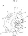
- FIG. 3 is a perspective view of the die head 14, and FIG. 4 is an exploded perspective view of the die head.
- the die head 14 is composed of a die holder 60, a die plate 70, and a die plate cover 80.
- the die holder 60 is made of carbon steel, and the die plate 70 and the die plate cover 80 are made of stainless steel (SUS). Understandably, the materials of the die holder 60, the die plate 70, and the die plate cover 80 are not limited to specific materials, and suitable materials can be selected as appropriate. For example, a corrosion-resistant material that is resistant to corrosion is selected depending on the type of resin.
- the die holder 60 is arranged on one side of the die plate 70 and the die plate cover 80 is arranged on the other side of the die plate 70.
- the die plate 70 is fixed to the die holder 60 and the die plate cover 80 is fixed to the die plate 70. Namely, the die holder 60, the die plate 70, and the die plate cover 80 are integrated.
- the die holder 60 has a cylindrical outer shape as a whole.
- Four fixing portions 61 are integrally formed on the side surface of the die holder 60.
- the four fixing portions 61 are arranged along the circumferential direction of the die holder 60.
- a through hole 62 is formed in each fixing portion 61.
- a rod for fixing the cutting mechanism (cutting process section 50) and the die holder 60 is inserted into each through hole 62. More specifically, a piston rod of a hydraulic cylinder provided in the cutting process section 50 is inserted into the through hole 62. By pulling back the piston rod inserted and retained in the through hole 62 into the cylinder tube, the cutting process section 50 and the die holder 60 are fixed to each other. From another point of view, the die plate 70 is sandwiched between the cutting process section 50 and the die holder 60.
- one surface 60b of the die holder 60 abuts to a downstream end face 41e of the housing 41.
- the one surface 60b of the die holder 60 abutting to the downstream end face 41e of the housing 41 is referred to as a "back surface 60b”
- the other one surface 60f of the die holder 60 on an opposite side of the back surface 60b is referred to as a "front surface 60f" in some cases.
- the downstream end face 41e of the housing 41 and the back surface 60b of the die holder 60 are in close contact with each other. Note that the die head 14 is fixed to the housing 41 by fixing the die holder 60 to the housing 41 by bolts.
- the die plate 70 has a cylindrical outer shape as a whole and the same or substantially the same outer diameter as that of the die holder 60.
- one surface 70b of the die plate 70 fixed to the die holder 60 abuts to the front surface 60f of the die holder 60.
- the one surface 70b of the die plate 70 abutting to the front surface 60f of the die holder 60 is referred to as a "back surface 70b" and the other one surface of the die plate 70 on an opposite side of the back surface 70b is referred to as a "front surface 70f" in some cases.
- the front surface 60f of the die holder 60 and the back surface 70b of the die plate 70 are in close contact with each other.
- a peripheral edge portion 71 is formed on the front surface 70f of the die plate 70 over the entire circumference of the die plate 70. Further, an outer annular region 72 is provided inside the peripheral edge portion 71, an inner annular region 73 is provided inside the outer annular region 72, and a central region 74 is provided inside the inner annular region 73. In other words, on the front surface 70f of the die plate 70, the peripheral edge portion 71, the outer annular region 72, the inner annular region 73, and the central region 74 are provided in this order from an outside to an inside in the radial direction.
- the outer annular region 72 is lower than the peripheral edge portion 71, and the inner annular region 73 is higher than the outer annular region 72. Also, the central region 74 is lower than the inner annular region 73.
- a through hole 75a is formed in the outer annular region 72 of the die plate 70, and a through hole 75b is formed in the central region 74 of the die plate 70.
- the number and arrangement of the through holes 75a and 75b are changed as appropriate in accordance with the size of the die plate 70 and the like.
- four through holes 75a are formed at equal intervals in the outer annular region 72, and one through hole 75b is formed in the central region 74.
- the four through holes 75a formed in the outer annular region 72 are arranged at equal intervals along the circumferential direction of the die plate 70. Namely, the fourth through holes 75a are arranged at intervals of 90 degrees.
- the through hole 75b formed in the central region 74 is arranged at the center of the die plate 70.
- the die plate 70 is fixed to the die holder 60 by bolts 76 inserted through the through holes 75a and 75b. Namely, the die plate 70 is fixed to the die holder 60 by five bolts 76.
- Each bolt 76 is a bolt with hole (socket bolt, cap bolt) having a hole 76a in its head. More specifically, each bolt 76 is a bolt with hexagonal hole (hexagon socket bolt, hexagon cap bolt) having a hexagon hole 76a in its head.
- a plurality of nozzles 77 are formed in the inner annular region 73 of the die plate 70.
- the inner annular region 73 is further divided into two regions with different heights. More specifically, the inner annular region 73 is divided into a region 73a adjacent to the outer annular region 72 and higher by one step than the outer annular region 72 and a region 73b adjacent to the region 73a and higher by one step than the region 73a.
- the nozzles 77 are provided in the region 73b of the inner annular region 73.
- Four nozzle groups each including a plurality of nozzles 77 are provided in the region 73b. Understandably, the plurality of nozzles 77 do not have to be arranged to form groups.
- the plurality of nozzles 77 may be arranged at regular intervals along the circumferential direction of the die plate 70.
- each nozzle 77 communicates with a common plate flow path 78 formed inside the die plate 70, and the other end of each nozzle 77 is open on the front surface 70f of the die plate 70.
- the plate flow path 78 communicating with the nozzle 77 communicates with a holder flow path 63 which is formed inside the die holder 60 and into which the molten resin conveyed by the screw 40 flows.
- a series of resin flow paths from the back surface 60b of the die holder 60 to the front surface 70f of the die plate 70 are provided in the die head 14.
- each nozzle 77 communicating with the plate flow path 78 is referred to as an "inlet”, and the other end of each nozzle 77 opening on the front surface 70f of the die plate 70 is referred as an "outlet" in some cases.
- the molten resin sent into the die head 14 by the rotation of the screw 40 flows into the die plate 70 via the die holder 60. More specifically, the molten resin flows through the holder flow path 63 in the die holder 60 into the plate flow path 78 in the die plate 70. The molten resin that has flown into the plate flow path 78 flows into each nozzle 77 from the inlet of each nozzle 77. The molten resin that has flown into the nozzle 77 passes through the nozzle 77 and flows out from the outlet of the nozzle 77. Namely, the molten resin is finally extruded into the cutting process section 50 of the cutting mechanism 15 from the outlet of each nozzle 77. As already described above, the molten resin is formed into a strand shape by passing through the nozzle 77.
- the die plate cover 80 has an annular outer shape as a whole and approximately the same shape and dimensions as those of the outer annular region 72 of the die plate 70. More specifically, the inner diameter of the die plate cover 80 is almost the same as the inner diameter of the outer annular region 72 of the die plate 70, and the outer diameter of die plate cover 80 is almost the same as the outer diameter of the outer annular region 72 of the die plate 70. In other words, the inner diameter of the die plate cover 80 is almost the same as the outer diameter of the inner annular region 73 of the die plate 70, and the outer diameter of the die plate cover 80 is almost the same as the inner diameter of the peripheral edge portion 71 of the die plate 70.
- the die plate cover 80 is fixed to the die plate 70 by a plurality of flat head bolts 81.
- the die plate cover 80 fixed to the die plate 70 covers substantially the entire outer annular region 72 of the die plate 70.
- the surface of the die plate cover 80 fixed to the die plate 70 and the surfaces of the peripheral edge portion 71 and the region 73a of the inner annular region 73 of the die plate 70 are substantially at the same height.
- the die plate cover 80 has the thickness corresponding to the height difference between the outer annular region 72 and the peripheral edge portion 71 of the die plate 70.
- the die plate cover 80 has the thickness corresponding to the height difference between the outer annular region 72 and the region 73a of the inner annular region 73 of the die plate 70.
- the thickness of the die plate cover 80 of this embodiment is approximately 3.0 mm. From another point of view, the height difference between the outer annular region 72 and the peripheral edge portion 71 is approximately 3.0 mm, and the height difference between the outer annular region 72 and the region 73a of the inner annular region 73 is also approximately 3.0 mm. Note that the region 73b of the inner annular region 73 where the nozzles 77 are provided is located at a slightly higher position than the surface of the die plate cover 80.
- the die plate cover 80 collectively covers the four through holes 75a provided in the outer annular region 72 of the die plate 70 and the heads of the bolts 76 inserted through the through holes 75a. Further, the through hole 75b provided in the central region 74 and the head of the bolt 76 inserted through the through hole 75b are covered with a center cover 90.
- the thickness of the center cover 90 is approximately 6.0 mm. Also, the center cover 90 is fixed to the die plate 70 by flat head bolts 91 similar to the flat head bolts 81.
- the through holes 75a and 75b provided in the front surface 70f of the die plate 70 and the heads of the bolts 76 inserted through the through holes 75a and 75b are covered with the cover members (the die plate cover 80, the center cover 90). Therefore, the molten resin extruded from the nozzle 77 and the pellet conveying water in the cutting process section 50 do not enter the through holes 75a and 75b and the holes 76a of the bolts 76.
- the die plate cover 80 and the center cover 90 are cover plates that prevent or suppress the contact and entry of molten resin and water into the through holes 75a and 75b and the holes 76a of the bolts 76.
- the die plate cover 80 located at the forefront of the die head 14 faces the pellet conveying water in the cutting process section 50. Therefore, the heat of the die head 14 is likely to be transferred to the pellet conveying water via the die plate cover 80, and the temperature of the die head 14 is likely to be lowered.
- the temperature of the die head 14 is lowered, the temperature of the molten resin passing through the die head 14 is lowered, and there is a risk that the fluidity of the molten resin is lowered or the molten resin is solidified.
- the decrease in fluidity and solidification of the molten resin in the die head 14 hinder the manufacture of good resin pellets. Therefore, it is desirable to maintain the temperature of the die head 14.
- the decrease in temperature of the die plate 70 in which the nozzles 77 are provided has a great influence on the quality of the resin pellets to be manufactured. Therefore, in order to manufacture good resin pellets, it is particularly desirable to maintain the temperature of the die plate 70. However, it is only the die plate cover 80 thinner than the die holder 60 and the die plate 70 that separates the die plate 70 and the pellet conveying water.
- the resin pellets may be manufactured without circulating water such as the pellet conveying water depending on the properties (especially melting point) of the resin raw material.
- the molten resin to be cut is extruded into the cutting process section 50 where no water is present. Namely, the molten resin is extruded into the air and is cut therein.
- the die plate cover 80 faces air rather than water such as the pellet conveying water. Therefore, heat dissipation from the die head 14 via the die plate cover 80 is smaller as compared with the case where the die plate cover 80 faces water. However, the heat of the die head 14 is still dissipated via the die plate cover 80.
- the method of cutting the molten resin in water is sometimes referred to as an "underwater cutting", and the method of cutting the molten resin in the air is sometimes referred to as a "hot cutting".
- the die plate cover 80 is designed to have a function of maintaining the temperature of the die head 14.
- the die plate cover 80 is made using a metal 3D printer and contains a heat insulating layer.
- the die plate cover 80 is a metal 3D printed product containing a heat insulating layer.
- FIG. 5A is a front view of the die plate cover 80.
- FIG. 5B is a cross-sectional view of the die plate cover 80 taken along the line A-A shown in FIG. 5A .
- An internal space (gap) 82 having a pressure lower than the atmospheric pressure is provided in (inside) the die plate cover 80.
- a vacuum internal space 82 is provided inside the die plate cover 80.
- a vacuum layer 83 as a heat insulating layer is formed inside the die plate cover 80.
- the internal space 82 is an annular space that follows the outer shape of the die plate cover 80 and is a continuous space. Also, the thickness (t) of the internal space 82 is approximately 0.5 mm.
- the vacuum layer 83 is an annular layer that follows the outer shape of the die plate cover 80 and is a continuous layer. Also, the thickness (t) of the vacuum layer 83 is approximately 0.5 mm. As already described above, the total thickness (T) of the die plate cover 80 is approximately 3.0 mm.
- FIG. 6 is a perspective view of the die plate cover 80.
- a plurality of communication holes 84a communicating with the internal space 82 are provided in one surface of the die plate cover 80.
- two communication holes 84a are provided.
- the two communication holes 84a are arranged at positions facing each other with the center of the die plate cover 80 interposed therebetween. In other words, the two communication holes 84a are arranged at positions separated by 180 degrees.
- Each communication hole 84a is airtightly closed by a sealing member 84b made of the same metal or the same kind of metal as the die plate cover 80. Namely, the sealing member 84b is a plug that closes the communication hole 84a.
- the vacuum internal space 82 (vacuum layer 83) is formed by airtightly closing the communication hole 84a by the sealing member 84b under a vacuum environment.
- the vacuum internal space 82 (vacuum layer 83) is formed by fitting and welding the sealing member 84b into the communication hole 84a in the vacuum chamber.
- the die plate cover 80 which is located at the forefront of the die head 14 and faces the water (pellet conveying water) and air in the cutting process section 50 has the heat insulating layer. Therefore, the amount of heat transferred from the die holder 60 and the die plate 70 to the water and air is reduced, and the decrease in temperature of the die head 14 is suppressed. Namely, the heat retention of the die head 14 is improved. As a result, the decrease in fluidity and solidification of the molten resin passing through the die head 14 are prevented or suppressed, and good resin pellets can be manufactured. Also, the energy required for maintaining the temperature of the die head 14 and the molten resin passing through the die head 14 at a predetermined temperature during operation of the resin pellet manufacturing system 1 can be reduced.
- dry start method extrusion and cutting of the molten resin are started before water such as pellet conveying water reaches the cutting process section 50. Therefore, the molten resin is temporarily cut in the air and in water afterward.
- the die plate cover 80 with which the water that has reached the cutting process section 50 is in contact, is provided with a heat insulating layer, and thus heat transfer from the die head 14 to the water is suppressed.
- Another start-up method of the resin pellet manufacturing system 1 is the "wet start method".
- the wet start method after the cutting process section 50 is filled with water such as the pellet conveying water and the temperature of the die head 14 rises to a predetermined temperature, the extrusion and cutting of the molten resin are started.
- the cutting process section 50 is filled with water such as the pellet conveying water and before the temperature of the die head 14 rises to a predetermined temperature, the extrusion and cutting of the molten resin are started.
- the die plate cover 80 facing the water in the cutting process section 50 has a heat insulating layer, the temperature of the die head 14 can be increased to a predetermined temperature in a short period of time.
- the thermal conductivity of water such as the pellet conveying water is 20 times or more that of air. Therefore, the improvement in heat retention of the die head 14 by the die plate cover 80 is particularly effective in the case of the underwater cutting. Also, a molten resin with a high melting point may lose its fluidity or solidify even by a slight temperature decrease. Therefore, the improvement in heat retention of the die head 14 by the die plate cover 80 is particularly effective in the case of processing a molten resin with a high melting point.
- FIG. 7 is an exploded perspective view showing a modification of the die plate cover 80.
- the die plate cover 80 shown in FIG. 7 is composed of a plate member 85, a plate member 86, and a spacer member 87.
- the plate member 85 and the plate member 86 face each other.
- the spacer member 87 is interposed between the plate members 85 and 86 facing each other.
- the die plate cover 80 shown in FIG. 7 has a stacked structure (sandwich structure).
- the spacer member 87 is formed in a frame shape having a plurality of openings 87a.
- the respective openings 87a are closed and the vacuum internal space 82 is formed.
- a plurality of independent vacuum internal spaces 82 are formed inside the die plate cover 80.
- the vacuum layer 83 as a heat insulating layer composed of a group of the plurality of vacuum internal spaces 82 is formed inside the die plate cover 80.
- the plate member 85 and the plate member 86 are joined by, for example, discharge plasma sintering or electron beam welding.
- FIG. 8A, FIG. 8B, and FIG. 8C are schematic diagrams each showing another modification of the die plate cover 80.
- a larger number of vacuum internal spaces 82 than those in the die plate cover 80 shown in FIG. 7 are provided inside the die plate covers 80 shown in these figures.
- the die plate cover 80 shown in each of FIG. 8A, FIG. 8B, and FIG. 8C is common with the die plate cover 80 shown in FIG. 7 in that a heat insulating layer (vacuum layer 83) composed of a group of the plurality of vacuum internal spaces 82 is formed.
- the planar shape of the internal space 82 provided in the die plate cover 80 shown in FIG. 8A is a hexagonal shape or a shape corresponding to a part of a hexagon.
- the planar shape of the internal space 82 provided in the die plate cover 80 shown in FIG. 8B is a circular shape or a shape corresponding to a part of a circle.
- the planar shape of the internal space 82 provided in the die plate cover 80 shown in FIG. 8C is a substantially trapezoidal shape.
- the die plate cover 80 shown in each of FIG. 8A, FIG. 8B, and FIG. 8C can be realized by a metal 3D printer, and can be realized also by a stacked structure (sandwich structure).
- a wall between two adjacent internal spaces 82 functions as a partition separating the internal spaces 82 and functions also as a rib that enhances the strength of the die plate cover 80. Therefore, forming the heat insulating layer (vacuum layer 83) by a group including a plurality of independent internal spaces 82 is advantageous in that it is possible to secure the volume of the heat insulating layer (vacuum layer 83) while avoiding the decrease in the strength of the die plate cover 80.
- the die head is used in an extruder.
- the application of the die head is not limited to the use in extruders.
- FIG. 9 is a schematic diagram showing an example of a system in which the die head 14 is used.
- An illustrated system 100 includes a polymerization tank 101, a gear pump 102, a motor 103, a speed reducer 104, and a cutting mechanism (pelletizer) 105.
- the die head 14 is arranged between the gear pump 102 and the cutting mechanism (pelletizer) 105.
- the gear pump 102 supplies a resin raw material and the like in the polymerization tank 101 to the die head 14.
- the resin raw material and the like supplied to the die head 14 pass through the die holder 60 and the die plate 70 and is extruded from the nozzle 77 of the die plate 70 to the cutting mechanism (pelletizer) 105.
- the thicknesses of the die plate cover and the heat insulating layer can be changed as appropriate. Understandably, the thickness of the die plate cover is preferably 3.0 mm or more and 10.0 mm or less in terms of strength and manufacturing cost. Further, when the thickness of the die plate cover is 3.0 mm or more and 10.0 mm or less, the thickness of the heat insulating layer is preferably 0.5 mm or more and 1.0 mm or less.
- any one of an internal space with the same pressure as the atmospheric pressure (air layer), an internal space with a pressure higher than the atmospheric pressure (high-pressure air layer), an internal space filled with an inert gas (for example, nitrogen gas or argon gas) (gas layer), and an internal space filled with a heat insulating material (heat insulating material layer) can be used to form the heat insulating layer.
- a heat insulating layer can be provided also in the cover plate other than the die plate cover arranged on the front surface of the die plate.
- the center cover 90 may also be provided with a heat insulating layer.
- the shape, structure, size, thickness, and others of the heat insulating layer of the die plate cover 80 and those of the heat insulating layer of the center cover 90 may be substantially the same or may be different from each other.
- the thickness of the heat insulating layer (vacuum layer 83) of the die plate cover 80 shown in FIG. 3 and FIG. 4 is 0.5 mm, but the thickness of the heat insulating layer (vacuum layer) provided in the center cover 90 thicker than the die plate cover 80 can be, for example, 1.0 mm.
- two or more types of heat insulating layers may be provided in one die plate cover or center cover.
- a vacuum layer and a gas layer may be provided in one die plate cover
- a vacuum layer and a heat insulating material layer may be provided in one die plate cover
- a vacuum layer, a gas layer, and a heat insulating material layer may be provided in one die plate cover.
- two or more heat insulating layers may be provided in one die plate cover.
- the lower heat insulating layer and the upper heat insulating layer may be the same type of heat insulating layers or different types of heat insulating layers.
- the surface of the die plate cover 80 and the surfaces of the peripheral edge portion 71 and the region 73a of the inner annular region 73 of the die plate 70 have substantially the same height, but an embodiment in which these surfaces have different heights is also one of embodiments of the present invention.
- Extruders include at least twin-screw extruders and single-screw extruders.
- the twin-screw extruders include at least a continuous intermeshed co-rotation twin-screw extruder and a continuous non-intermeshed counter-rotation twin-screw extruder.
Landscapes
- Engineering & Computer Science (AREA)
- Mechanical Engineering (AREA)
- Manufacturing & Machinery (AREA)
- Processing And Handling Of Plastics And Other Materials For Molding In General (AREA)
Abstract
Description
- The present invention relates to a die plate cover, a die head, an extruder, and a method of manufacturing resin pellets.
- An extruder configured to manufacture resin pellets by cutting a molten resin while extruding it has been known. The extruder conveys the molten resin while kneading it and extrudes it from a die head. Further, the extruder cuts the molten resin continuously extruded from the die head to a predetermined length. For example, Patent Document 1 (
Japanese Unexamined Patent Application Publication No. 2019-188638 - Patent Document 1:
Japanese Unexamined Patent Application Publication No. 2019-188638 - In order to manufacture good resin pellets, it is desirable to maintain the temperature of the die head from which the molten resin is extruded.
- Other problems and novel features will be apparent from the descriptions of this specification and accompanying drawings.
- According to one embodiment, a die plate cover contains a heat insulating layer and is attached to one surface of a die plate from which a molten resin is extruded. The die plate cover attached to the die plate is configured to cover a plurality of through holes formed in the one surface of the die plate and bolts inserted through the respective through holes.
- According to one embodiment, it is possible to maintain the temperature of the die head and manufacture good resin pellets.
-
-
FIG. 1 is a schematic diagram showing a resin pellet manufacturing system according to one embodiment; -
FIG. 2 is a cross-sectional view schematically showing a structure of a die head and a cutting mechanism; -
FIG. 3 is a perspective view of the die head; -
FIG. 4 is an exploded perspective view of the die head; -
FIG. 5A is a front view of a die plate cover; -
FIG. 5B is a cross-sectional view of the die plate cover taken along the line A-A shown inFIG. 5A ; -
FIG. 6 is a perspective view of the die plate cover; -
FIG. 7 is a perspective view showing a modification of the die plate cover; -
FIG. 8A is a schematic diagram showing another modification of the die plate cover; -
FIG. 8B is a schematic diagram showing another modification of the die plate cover; -
FIG. 8C is a schematic diagram showing another modification of the die plate cover; and -
FIG. 9 is a schematic diagram showing an example of a system in which the die head is used. - Hereinafter, one embodiment will be described in detail with reference to drawings. Note that the members and devices having the same or substantially the same function are denoted by the same reference characters throughout the drawings for describing the embodiment, and the repetitive description thereof will be omitted.
-
FIG. 1 is a schematic diagram showing a resin pellet manufacturing system including an extruder. A resinpellet manufacturing system 1 shown inFIG. 1 is composed of anextruder 10 as a main equipment and a plurality ofauxiliary equipments 20. Theextruder 10 includes amotor 11, aspeed reducer 12, akneading processor 13, adie head 14, and a cutting mechanism (pelletizer, cutter unit) 15. Theauxiliary equipments 20 include atank 21, acirculation pump 22, adehydrator 23, aconveying hopper 24, ablower 25, and apellet silo 26, and these equipments are connected by pipes as appropriate. - The
tank 21 is connected to thecirculation pump 22 via apipe 27a, and thecirculation pump 22 is connected to the extruder 10 (cutting mechanism 15) via apipe 27b. Further, thedehydrator 23 is connected to the extruder 10 (cutting mechanism 15) via apipe 27c and is connected also to thetank 21 via apipe 27d. Namely, thepipes tank 21, thecirculation pump 22, thecutting mechanism 15, and thedehydrator 23. Thetank 21 stores liquid. In this embodiment, thetank 21 stores water. The water in thetank 21 is circulated through thetank 21, thecirculation pump 22, thecutting mechanism 15, thedehydrator 23, and thetank 21 in this order by the action of thecirculation pump 22. However, a part of the water flowing from thecutting mechanism 15 to thedehydrator 23 is split at abranch portion 28 and returned to thetank 21 through apipe 27e. The water circulating in the system functions as conveying water for conveying the resin pellets and functions also as cooling water. In the following description, the water circulating in the system may be referred to as "pellet conveying water" in some cases. - In the resin
pellet manufacturing system 1 shown inFIG. 1 , for example, the resin pellets are manufactured through the following process. First, a resin raw material is supplied to the extruder 10 (raw material supply step). More specifically, a resin raw material is fed to araw material hopper 30 as a raw material inlet of theextruder 10. The resin raw material supplied to theextruder 10 is, for example, a thermoplastic resin. Additives and the like are added to the resin raw material as necessary. - The resin raw material fed to the
raw material hopper 30 is supplied to the kneadingprocessor 13. The resin raw material supplied to the kneadingprocessor 13 is melted (melting step). Further, the molten resin raw material (molten resin) is conveyed while being kneaded (mixed) (kneading/conveying step). More specifically, the molten resin is sent forward while being kneaded by the rotation of ascrew 40 provided in the kneadingprocessor 13, and is supplied to thedie head 14. Namely, in the kneading/conveying step, kneading and conveyance of the molten resin are simultaneously performed in parallel. Also, the resin raw material is melted by the heat generated by shear stress mainly caused by the rotation of thescrew 40. Understandably, when melting the resin raw material, heat may be applied to the resin raw material by such means as a heater in some cases. - The molten resin supplied to the
die head 14 passes through thedie head 14 and is continuously extruded from the die head 14 (extrusion step). In other words, the molten resin is formed into a strand shape (string shape, rope shape) by passing through thedie head 14. -
FIG. 2 is a cross-sectional view schematically showing the structure of thedie head 14 and thecutting mechanism 15. A cutting process section (cutting process space) 50 of thecutting mechanism 15 is provided ahead of thedie head 14. The molten resin that has passed through thedie head 14 is extruded (discharged) into thecutting process section 50 of thecutting mechanism 15. In other words, thecutting process section 50 of thecutting mechanism 15 receives molten resin extruded from thedie head 14. - The
cutting process section 50 is provided on the flow path of the pellet conveying water. Therefore, when the pellet conveying water circulates in the resinpellet manufacturing system 1, thecutting process section 50 is filled with the pellet conveying water. Namely, the molten resin that has passed through thedie head 14 is extruded into water (into the pellet conveying water). - The
cutting mechanism 15 has acutter head 51 that is rotationally driven in thecutting process section 50, and a plurality of cutter blades are attached to thecutter head 51. The strand-shaped molten resin extruded from thedie head 14 to thecutting process section 50 is cut to a predetermined length by the cutter head 51 (cutter blade) and solidified in the water (in the pellet conveying water) (cutting/solidifying step, pelletizing step). In other words, the molten resin extruded into a strand shape is divided into pellets. As a result, resin pellets having a predetermined size (length and thickness) are manufactured. The technique of cutting molten resin in water is referred to as "underwater cutting" in some cases. - Referring to
FIG. 1 again, a mixture (slurry) of the resin pellets and the pellet conveying water moves to thedehydrator 23 through thepipe 27c. In thedehydrator 23, the resin pellets and the pellet conveying water are separated (dehydration step). The pellet conveying water separated from the resin pellets flows (returns) to thetank 21 through thepipe 27d. On the other hand, the resin pellets from which the pellet conveying water has been separated (removed) move to the conveyinghopper 24. - The conveying
hopper 24 is connected to thepellet silo 26 via apipe 29. The resin pellets moved to the conveyinghopper 24 are sent to thepellet silo 26 through thepipe 29 by the airflow generated by the blower 25 (transfer step). The resin pellets sent to thepellet silo 26 are stored in the pellet silo 26 (storage step) . Namely, the resin pellets are air-conveyed from the conveyinghopper 24 to thepellet silo 26. Also, thepellet silo 26 is a container that stores the air-conveyed resin pellets. - In the resin
pellet manufacturing system 1, resin pellets are manufactured through the process described above. Understandably, the resinpellet manufacturing system 1 can be modified in various ways in accordance with the types and characteristics of the resin raw material and resin pellets. Also, the method of manufacturing resin pellets can be modified in various ways in accordance with the types and characteristics of the resin raw material and resin pellets. For example, a centrifugal dewatering dryer may be provided between the dehydrator 23 and thepellet silo 26 shown inFIG. 1 . The centrifugal dewatering dryer removes from the resin pellets the water that has not been removed by thedehydrator 23. In this case, the method of manufacturing resin pellets includes a centrifugal dewatering step, a drying step, and the like. Also, the resinpellet manufacturing system 1 may be provided with sorting means such as a sieve for sorting the resin pellets based on size. In this case, the method of manufacturing resin pellets includes a sorting step. - Next, the
extruder 10 shown inFIG. 1 will be described in more detail. As described above, theextruder 10 includes themotor 11, thespeed reducer 12, the kneadingprocessor 13, thedie head 14, and the cutting mechanism (pelletizer, cutter unit) 15. - The
motor 11 is a drive source of theextruder 10. More specifically, themotor 11 is a drive source of the kneadingprocessor 13. The rotational driving force output from themotor 11 is input to thescrew 40 of the kneadingprocessor 13 via thespeed reducer 12 to rotate thescrew 40. Thespeed reducer 12 reduces the speed of the rotational driving force output from themotor 11 and increases the torque of the rotational driving force input to thescrew 40. - The
screw 40 has a helical blade and is rotatably provided in ahousing 41. Theraw material hopper 30 is provided at one end of thehousing 41 in a longitudinal direction, and thedie head 14 is provided at the other end of thehousing 41 in the longitudinal direction. Note that the longitudinal direction of thehousing 41 coincides with an axial direction of thescrew 40. - Behind the
screw 40 shown inFIG. 1 , another screw similar to thescrew 40 is provided. The other screw is aligned parallel to thescrew 40 and is rotated by themotor 11 in the same manner as thescrew 40. Namely, theextruder 10 includes two screws parallel to each other and is generally referred to as a "twin-screw kneading extruder". In the following description, thescrew 40 and the other screw aligned parallel to thescrew 40 are collectively referred to as the "screw 40". - The resin raw material fed to the
raw material hopper 30 is melted by the heat generated by shear stress mainly caused by the rotation of thescrew 40. Understandably, the kneadingprocessor 13 is provided with heating means (heater) for heating the resin raw material and adjusting the temperature of the resin material as necessary. The molten resin raw material (molten resin) is conveyed while being kneaded by the rotation of thescrew 40. Specifically, the molten resin is conveyed by the rotation of thescrew 40 from one end side of thehousing 41 in the longitudinal direction where theraw material hopper 30 is provided (one end side of thescrew 40 in the axial direction) to the other end side of thehousing 41 in the longitudinal direction where thedie head 14 is provided (the other end side of thescrew 40 in the axial direction). - As described above, the molten resin is conveyed in the longitudinal direction of the
housing 41 while being kneaded by therotating screw 40. Namely, the longitudinal direction of the housing 41 (axial direction of the screw 40) is the conveying direction of the molten resin. Thus, in the following description, one end side of thehousing 41 in the longitudinal direction where theraw material hopper 30 is provided (one end side of thescrew 40 in the axial direction) is defined as an "upstream side" of the conveying direction, and the other end side of thehousing 41 in the longitudinal direction where thedie head 14 is provided (the other end side of thescrew 40 in the axial direction) is defined as a "downstream side". - As shown in
FIG. 2 , thecutting process section 50 is provided between thepipe 27b and thepipe 27c. Therefore, when thecirculation pump 22 is actuated, the pellet conveying water flows into thecutting process section 50 through thepipe 27b, and the pellet conveying water flows out of thecutting process section 50 through thepipe 27c. As a result, thecutting process section 50 is filled with the pellet conveying water, and the molten resin that has passed through thedie head 14 is extruded into the pellet conveying water that fills thecutting process section 50. - A plurality of cutter blades are attached to the
cutter head 51 rotationally driven in thecutting process section 50. These cutter blades are attached to one surface of thecutter head 51 facing one surface of thedie head 14 from which the molten resin is extruded. The plurality of cutter blades attached to one surface of thecutter head 51 are arranged at a predetermined pitch along the rotation direction of thecutter head 51. Therefore, the length of the resin pellets to be manufactured depends on the interval (facing distance) between thedie head 14 and thecutter head 51, the rotational speed of thecutter head 51, the pitch of the cutter blades, and the like. Thus, the length of the resin pellets to be manufactured can be changed by adjusting the interval between thedie head 14 and thecutter head 51, the rotational speed of thecutter head 51, the pitch of the cutter blades, and the like. - Note that the thickness of the resin pellets to be manufactured depends on the inner diameter of a
nozzle 77 of thedie plate 70, which will be described later. Therefore, the thickness of the resin pellets to be manufactured can be changed by using thedie plate 70 having thenozzle 77 with a different inner diameter. - The
die head 14 is attached to the end of thehousing 41 in which thescrew 40 is accommodated. More specifically, thedie head 14 is attached to the downstream end of thehousing 41. -
FIG. 3 is a perspective view of thedie head 14, andFIG. 4 is an exploded perspective view of the die head. Thedie head 14 is composed of adie holder 60, adie plate 70, and adie plate cover 80. Thedie holder 60 is made of carbon steel, and thedie plate 70 and thedie plate cover 80 are made of stainless steel (SUS). Understandably, the materials of thedie holder 60, thedie plate 70, and thedie plate cover 80 are not limited to specific materials, and suitable materials can be selected as appropriate. For example, a corrosion-resistant material that is resistant to corrosion is selected depending on the type of resin. - The
die holder 60 is arranged on one side of thedie plate 70 and thedie plate cover 80 is arranged on the other side of thedie plate 70. Thedie plate 70 is fixed to thedie holder 60 and thedie plate cover 80 is fixed to thedie plate 70. Namely, thedie holder 60, thedie plate 70, and thedie plate cover 80 are integrated. - The
die holder 60 has a cylindrical outer shape as a whole. Four fixingportions 61 are integrally formed on the side surface of thedie holder 60. The four fixingportions 61 are arranged along the circumferential direction of thedie holder 60. A throughhole 62 is formed in each fixingportion 61. A rod for fixing the cutting mechanism (cutting process section 50) and thedie holder 60 is inserted into each throughhole 62. More specifically, a piston rod of a hydraulic cylinder provided in thecutting process section 50 is inserted into the throughhole 62. By pulling back the piston rod inserted and retained in the throughhole 62 into the cylinder tube, thecutting process section 50 and thedie holder 60 are fixed to each other. From another point of view, thedie plate 70 is sandwiched between the cuttingprocess section 50 and thedie holder 60. - As shown in
FIG. 2 , when thedie head 14 has been fixed to thehousing 41, onesurface 60b of thedie holder 60 abuts to adownstream end face 41e of thehousing 41. In the following description, the onesurface 60b of thedie holder 60 abutting to thedownstream end face 41e of thehousing 41 is referred to as a "back surface 60b", and the other onesurface 60f of thedie holder 60 on an opposite side of theback surface 60b is referred to as a "front surface 60f" in some cases. Namely, when thedie head 14 has been fixed to thehousing 41, thedownstream end face 41e of thehousing 41 and theback surface 60b of thedie holder 60 are in close contact with each other. Note that thedie head 14 is fixed to thehousing 41 by fixing thedie holder 60 to thehousing 41 by bolts. - As shown in
FIG. 3 andFIG. 4 , thedie plate 70 has a cylindrical outer shape as a whole and the same or substantially the same outer diameter as that of thedie holder 60. As shown inFIG. 2 , onesurface 70b of thedie plate 70 fixed to thedie holder 60 abuts to thefront surface 60f of thedie holder 60. In the following description, the onesurface 70b of thedie plate 70 abutting to thefront surface 60f of thedie holder 60 is referred to as a "back surface 70b" and the other one surface of thedie plate 70 on an opposite side of theback surface 70b is referred to as a "front surface 70f" in some cases. Namely, when thedie plate 70 has been fixed to thedie holder 60, thefront surface 60f of thedie holder 60 and theback surface 70b of thedie plate 70 are in close contact with each other. - As shown in
FIG. 4 , aperipheral edge portion 71 is formed on thefront surface 70f of thedie plate 70 over the entire circumference of thedie plate 70. Further, an outerannular region 72 is provided inside theperipheral edge portion 71, an innerannular region 73 is provided inside the outerannular region 72, and acentral region 74 is provided inside the innerannular region 73. In other words, on thefront surface 70f of thedie plate 70, theperipheral edge portion 71, the outerannular region 72, the innerannular region 73, and thecentral region 74 are provided in this order from an outside to an inside in the radial direction. When the axial direction of thedie head 14 is defined as the height direction, the outerannular region 72 is lower than theperipheral edge portion 71, and the innerannular region 73 is higher than the outerannular region 72. Also, thecentral region 74 is lower than the innerannular region 73. - A through
hole 75a is formed in the outerannular region 72 of thedie plate 70, and a throughhole 75b is formed in thecentral region 74 of thedie plate 70. The number and arrangement of the throughholes die plate 70 and the like. In this embodiment, four throughholes 75a are formed at equal intervals in the outerannular region 72, and one throughhole 75b is formed in thecentral region 74. The four throughholes 75a formed in the outerannular region 72 are arranged at equal intervals along the circumferential direction of thedie plate 70. Namely, the fourth throughholes 75a are arranged at intervals of 90 degrees. The throughhole 75b formed in thecentral region 74 is arranged at the center of thedie plate 70. - The
die plate 70 is fixed to thedie holder 60 bybolts 76 inserted through the throughholes die plate 70 is fixed to thedie holder 60 by fivebolts 76. Eachbolt 76 is a bolt with hole (socket bolt, cap bolt) having ahole 76a in its head. More specifically, eachbolt 76 is a bolt with hexagonal hole (hexagon socket bolt, hexagon cap bolt) having ahexagon hole 76a in its head. - A plurality of
nozzles 77 are formed in the innerannular region 73 of thedie plate 70. Here, the innerannular region 73 is further divided into two regions with different heights. More specifically, the innerannular region 73 is divided into aregion 73a adjacent to the outerannular region 72 and higher by one step than the outerannular region 72 and aregion 73b adjacent to theregion 73a and higher by one step than theregion 73a. Thenozzles 77 are provided in theregion 73b of the innerannular region 73. Four nozzle groups each including a plurality ofnozzles 77 are provided in theregion 73b. Understandably, the plurality ofnozzles 77 do not have to be arranged to form groups. For example, the plurality ofnozzles 77 may be arranged at regular intervals along the circumferential direction of thedie plate 70. - As shown in
FIG. 2 , one end of eachnozzle 77 communicates with a commonplate flow path 78 formed inside thedie plate 70, and the other end of eachnozzle 77 is open on thefront surface 70f of thedie plate 70. Further, theplate flow path 78 communicating with thenozzle 77 communicates with aholder flow path 63 which is formed inside thedie holder 60 and into which the molten resin conveyed by thescrew 40 flows. As described above, a series of resin flow paths from theback surface 60b of thedie holder 60 to thefront surface 70f of thedie plate 70 are provided in thedie head 14. In the following description, one end of eachnozzle 77 communicating with theplate flow path 78 is referred to as an "inlet", and the other end of eachnozzle 77 opening on thefront surface 70f of thedie plate 70 is referred as an "outlet" in some cases. - The molten resin sent into the
die head 14 by the rotation of thescrew 40 flows into thedie plate 70 via thedie holder 60. More specifically, the molten resin flows through theholder flow path 63 in thedie holder 60 into theplate flow path 78 in thedie plate 70. The molten resin that has flown into theplate flow path 78 flows into eachnozzle 77 from the inlet of eachnozzle 77. The molten resin that has flown into thenozzle 77 passes through thenozzle 77 and flows out from the outlet of thenozzle 77. Namely, the molten resin is finally extruded into thecutting process section 50 of thecutting mechanism 15 from the outlet of eachnozzle 77. As already described above, the molten resin is formed into a strand shape by passing through thenozzle 77. - As shown in
FIG. 3 andFIG. 4 , thedie plate cover 80 has an annular outer shape as a whole and approximately the same shape and dimensions as those of the outerannular region 72 of thedie plate 70. More specifically, the inner diameter of thedie plate cover 80 is almost the same as the inner diameter of the outerannular region 72 of thedie plate 70, and the outer diameter ofdie plate cover 80 is almost the same as the outer diameter of the outerannular region 72 of thedie plate 70. In other words, the inner diameter of thedie plate cover 80 is almost the same as the outer diameter of the innerannular region 73 of thedie plate 70, and the outer diameter of thedie plate cover 80 is almost the same as the inner diameter of theperipheral edge portion 71 of thedie plate 70. - The
die plate cover 80 is fixed to thedie plate 70 by a plurality offlat head bolts 81. Thedie plate cover 80 fixed to thedie plate 70 covers substantially the entire outerannular region 72 of thedie plate 70. The surface of thedie plate cover 80 fixed to thedie plate 70 and the surfaces of theperipheral edge portion 71 and theregion 73a of the innerannular region 73 of thedie plate 70 are substantially at the same height. Namely, thedie plate cover 80 has the thickness corresponding to the height difference between the outerannular region 72 and theperipheral edge portion 71 of thedie plate 70. Also, thedie plate cover 80 has the thickness corresponding to the height difference between the outerannular region 72 and theregion 73a of the innerannular region 73 of thedie plate 70. The thickness of thedie plate cover 80 of this embodiment is approximately 3.0 mm. From another point of view, the height difference between the outerannular region 72 and theperipheral edge portion 71 is approximately 3.0 mm, and the height difference between the outerannular region 72 and theregion 73a of the innerannular region 73 is also approximately 3.0 mm. Note that theregion 73b of the innerannular region 73 where thenozzles 77 are provided is located at a slightly higher position than the surface of thedie plate cover 80. - The
die plate cover 80 collectively covers the four throughholes 75a provided in the outerannular region 72 of thedie plate 70 and the heads of thebolts 76 inserted through the throughholes 75a. Further, the throughhole 75b provided in thecentral region 74 and the head of thebolt 76 inserted through the throughhole 75b are covered with acenter cover 90. The thickness of thecenter cover 90 is approximately 6.0 mm. Also, thecenter cover 90 is fixed to thedie plate 70 byflat head bolts 91 similar to theflat head bolts 81. - In this embodiment, the through
holes front surface 70f of thedie plate 70 and the heads of thebolts 76 inserted through the throughholes die plate cover 80, the center cover 90). Therefore, the molten resin extruded from thenozzle 77 and the pellet conveying water in thecutting process section 50 do not enter the throughholes holes 76a of thebolts 76. In other words, thedie plate cover 80 and thecenter cover 90 are cover plates that prevent or suppress the contact and entry of molten resin and water into the throughholes holes 76a of thebolts 76. - Referring to
FIG. 2 again, thedie plate cover 80 located at the forefront of thedie head 14 faces the pellet conveying water in thecutting process section 50. Therefore, the heat of thedie head 14 is likely to be transferred to the pellet conveying water via thedie plate cover 80, and the temperature of thedie head 14 is likely to be lowered. When the temperature of thedie head 14 is lowered, the temperature of the molten resin passing through thedie head 14 is lowered, and there is a risk that the fluidity of the molten resin is lowered or the molten resin is solidified. On the other hand, the decrease in fluidity and solidification of the molten resin in thedie head 14 hinder the manufacture of good resin pellets. Therefore, it is desirable to maintain the temperature of thedie head 14. In particular, the decrease in temperature of thedie plate 70 in which thenozzles 77 are provided has a great influence on the quality of the resin pellets to be manufactured. Therefore, in order to manufacture good resin pellets, it is particularly desirable to maintain the temperature of thedie plate 70. However, it is only thedie plate cover 80 thinner than thedie holder 60 and thedie plate 70 that separates thedie plate 70 and the pellet conveying water. - Note that the resin pellets may be manufactured without circulating water such as the pellet conveying water depending on the properties (especially melting point) of the resin raw material. In such a method of manufacturing resin pellets, the molten resin to be cut is extruded into the
cutting process section 50 where no water is present. Namely, the molten resin is extruded into the air and is cut therein. In this case, thedie plate cover 80 faces air rather than water such as the pellet conveying water. Therefore, heat dissipation from thedie head 14 via thedie plate cover 80 is smaller as compared with the case where thedie plate cover 80 faces water. However, the heat of thedie head 14 is still dissipated via thedie plate cover 80. Therefore, even when manufacturing resin pellets without circulating water, it is desirable to maintain the temperature of thedie head 14 in order to manufacture good resin pellets. The method of cutting the molten resin in water is sometimes referred to as an "underwater cutting", and the method of cutting the molten resin in the air is sometimes referred to as a "hot cutting". - As described above, regardless of whether the cutting method used for manufacturing the resin pellets is the underwater cutting or the hot cutting, it is desirable to maintain the temperature of the
die head 14 in order to manufacture good resin pellets. However, a large amount of energy is required to maintain the temperature of thedie head 14 under the condition that the heat of thedie head 14 continues to be dissipated via thedie plate cover 80. For example, it is necessary to set the higher heating temperature of thedie head 14 in consideration of the decrease in temperature due to heat dissipation. In addition, it is necessary to set the higher heating temperature of the molten resin in consideration of the decrease in temperature in thedie head 14. As a result, the running cost of theextruder 10 increases, and the manufacturing cost of resin pellets increases. - Therefore, in this embodiment, the
die plate cover 80 is designed to have a function of maintaining the temperature of thedie head 14. Specifically, thedie plate cover 80 is made using a metal 3D printer and contains a heat insulating layer. In other words, thedie plate cover 80 is a metal 3D printed product containing a heat insulating layer. -
FIG. 5A is a front view of thedie plate cover 80.FIG. 5B is a cross-sectional view of thedie plate cover 80 taken along the line A-A shown inFIG. 5A . An internal space (gap) 82 having a pressure lower than the atmospheric pressure is provided in (inside) thedie plate cover 80. In other words, a vacuuminternal space 82 is provided inside thedie plate cover 80. As a result, avacuum layer 83 as a heat insulating layer is formed inside thedie plate cover 80. - The
internal space 82 is an annular space that follows the outer shape of thedie plate cover 80 and is a continuous space. Also, the thickness (t) of theinternal space 82 is approximately 0.5 mm. In other words, thevacuum layer 83 is an annular layer that follows the outer shape of thedie plate cover 80 and is a continuous layer. Also, the thickness (t) of thevacuum layer 83 is approximately 0.5 mm. As already described above, the total thickness (T) of thedie plate cover 80 is approximately 3.0 mm. -
FIG. 6 is a perspective view of thedie plate cover 80. A plurality ofcommunication holes 84a communicating with theinternal space 82 are provided in one surface of thedie plate cover 80. In this embodiment, twocommunication holes 84a are provided. The twocommunication holes 84a are arranged at positions facing each other with the center of thedie plate cover 80 interposed therebetween. In other words, the twocommunication holes 84a are arranged at positions separated by 180 degrees. Eachcommunication hole 84a is airtightly closed by a sealingmember 84b made of the same metal or the same kind of metal as thedie plate cover 80. Namely, the sealingmember 84b is a plug that closes thecommunication hole 84a. - The vacuum internal space 82 (vacuum layer 83) is formed by airtightly closing the
communication hole 84a by the sealingmember 84b under a vacuum environment. For example, the vacuum internal space 82 (vacuum layer 83) is formed by fitting and welding the sealingmember 84b into thecommunication hole 84a in the vacuum chamber. - In this embodiment, the
die plate cover 80 which is located at the forefront of thedie head 14 and faces the water (pellet conveying water) and air in thecutting process section 50 has the heat insulating layer. Therefore, the amount of heat transferred from thedie holder 60 and thedie plate 70 to the water and air is reduced, and the decrease in temperature of thedie head 14 is suppressed. Namely, the heat retention of thedie head 14 is improved. As a result, the decrease in fluidity and solidification of the molten resin passing through thedie head 14 are prevented or suppressed, and good resin pellets can be manufactured. Also, the energy required for maintaining the temperature of thedie head 14 and the molten resin passing through thedie head 14 at a predetermined temperature during operation of the resinpellet manufacturing system 1 can be reduced. - One of the start-up methods of the resin
pellet manufacturing system 1 is the "dry start method". In the dry start method, extrusion and cutting of the molten resin are started before water such as pellet conveying water reaches thecutting process section 50. Therefore, the molten resin is temporarily cut in the air and in water afterward. - In the dry start method described above, when the water that has reached the
cutting process section 50 comes into contact with thedie head 14, the heat of thedie head 14 is rapidly removed. However, in this embodiment, thedie plate cover 80, with which the water that has reached thecutting process section 50 is in contact, is provided with a heat insulating layer, and thus heat transfer from thedie head 14 to the water is suppressed. - Another start-up method of the resin
pellet manufacturing system 1 is the "wet start method". In one aspect of the wet start method, after thecutting process section 50 is filled with water such as the pellet conveying water and the temperature of thedie head 14 rises to a predetermined temperature, the extrusion and cutting of the molten resin are started. Further, in another aspect of the wet start method, after thecutting process section 50 is filled with water such as the pellet conveying water and before the temperature of thedie head 14 rises to a predetermined temperature, the extrusion and cutting of the molten resin are started. Namely, in the wet start method, it is necessary to increase the temperature of thedie head 14 in the state where thedie head 14 faces the water in thecutting process section 50. In this embodiment, since thedie plate cover 80 facing the water in thecutting process section 50 has a heat insulating layer, the temperature of thedie head 14 can be increased to a predetermined temperature in a short period of time. - The thermal conductivity of water such as the pellet conveying water is 20 times or more that of air. Therefore, the improvement in heat retention of the
die head 14 by thedie plate cover 80 is particularly effective in the case of the underwater cutting. Also, a molten resin with a high melting point may lose its fluidity or solidify even by a slight temperature decrease. Therefore, the improvement in heat retention of thedie head 14 by thedie plate cover 80 is particularly effective in the case of processing a molten resin with a high melting point. -
FIG. 7 is an exploded perspective view showing a modification of thedie plate cover 80. Thedie plate cover 80 shown inFIG. 7 is composed of aplate member 85, aplate member 86, and aspacer member 87. Theplate member 85 and theplate member 86 face each other. Thespacer member 87 is interposed between theplate members die plate cover 80 shown inFIG. 7 has a stacked structure (sandwich structure). - The
spacer member 87 is formed in a frame shape having a plurality ofopenings 87a. When theplate member 85 and theplate member 86 are joined under a vacuum environment with thespacer member 87 interposed therebetween, therespective openings 87a are closed and the vacuuminternal space 82 is formed. Namely, a plurality of independent vacuuminternal spaces 82 are formed inside thedie plate cover 80. As a result, thevacuum layer 83 as a heat insulating layer composed of a group of the plurality of vacuuminternal spaces 82 is formed inside thedie plate cover 80. Theplate member 85 and theplate member 86 are joined by, for example, discharge plasma sintering or electron beam welding. -
FIG. 8A, FIG. 8B, and FIG. 8C are schematic diagrams each showing another modification of thedie plate cover 80. A larger number of vacuuminternal spaces 82 than those in thedie plate cover 80 shown inFIG. 7 are provided inside the die plate covers 80 shown in these figures. Understandably, thedie plate cover 80 shown in each ofFIG. 8A, FIG. 8B, and FIG. 8C is common with thedie plate cover 80 shown inFIG. 7 in that a heat insulating layer (vacuum layer 83) composed of a group of the plurality of vacuuminternal spaces 82 is formed. - The planar shape of the
internal space 82 provided in thedie plate cover 80 shown inFIG. 8A is a hexagonal shape or a shape corresponding to a part of a hexagon. The planar shape of theinternal space 82 provided in thedie plate cover 80 shown inFIG. 8B is a circular shape or a shape corresponding to a part of a circle. The planar shape of theinternal space 82 provided in thedie plate cover 80 shown inFIG. 8C is a substantially trapezoidal shape. - Note that the
die plate cover 80 shown in each ofFIG. 8A, FIG. 8B, and FIG. 8C can be realized by a metal 3D printer, and can be realized also by a stacked structure (sandwich structure). - A wall between two adjacent
internal spaces 82 functions as a partition separating theinternal spaces 82 and functions also as a rib that enhances the strength of thedie plate cover 80. Therefore, forming the heat insulating layer (vacuum layer 83) by a group including a plurality of independentinternal spaces 82 is advantageous in that it is possible to secure the volume of the heat insulating layer (vacuum layer 83) while avoiding the decrease in the strength of thedie plate cover 80. - In the above embodiment, the case where the die head is used in an extruder has been described. However, the application of the die head is not limited to the use in extruders.
-
FIG. 9 is a schematic diagram showing an example of a system in which thedie head 14 is used. An illustratedsystem 100 includes apolymerization tank 101, agear pump 102, amotor 103, aspeed reducer 104, and a cutting mechanism (pelletizer) 105. Thedie head 14 is arranged between thegear pump 102 and the cutting mechanism (pelletizer) 105. - The
gear pump 102 supplies a resin raw material and the like in thepolymerization tank 101 to thedie head 14. The resin raw material and the like supplied to thedie head 14 pass through thedie holder 60 and thedie plate 70 and is extruded from thenozzle 77 of thedie plate 70 to the cutting mechanism (pelletizer) 105. - In the foregoing, the invention made by the inventors of this application has been specifically described based on the embodiment and example. However, it is needless to say that the present invention is not limited to the above-described embodiment and example and various modifications can be made within the range not departing from the gist thereof. For example, the thicknesses of the die plate cover and the heat insulating layer can be changed as appropriate. Understandably, the thickness of the die plate cover is preferably 3.0 mm or more and 10.0 mm or less in terms of strength and manufacturing cost. Further, when the thickness of the die plate cover is 3.0 mm or more and 10.0 mm or less, the thickness of the heat insulating layer is preferably 0.5 mm or more and 1.0 mm or less.
- Instead of an internal space with a pressure lower than the atmospheric pressure (vacuum layer/low-pressure air layer), any one of an internal space with the same pressure as the atmospheric pressure (air layer), an internal space with a pressure higher than the atmospheric pressure (high-pressure air layer), an internal space filled with an inert gas (for example, nitrogen gas or argon gas) (gas layer), and an internal space filled with a heat insulating material (heat insulating material layer) can be used to form the heat insulating layer.
- A heat insulating layer can be provided also in the cover plate other than the die plate cover arranged on the front surface of the die plate. For example, in addition to the
die plate cover 80 shown inFIG. 3 andFIG. 4 , thecenter cover 90 may also be provided with a heat insulating layer. In this case, the shape, structure, size, thickness, and others of the heat insulating layer of thedie plate cover 80 and those of the heat insulating layer of thecenter cover 90 may be substantially the same or may be different from each other. For example, the thickness of the heat insulating layer (vacuum layer 83) of thedie plate cover 80 shown inFIG. 3 andFIG. 4 is 0.5 mm, but the thickness of the heat insulating layer (vacuum layer) provided in thecenter cover 90 thicker than thedie plate cover 80 can be, for example, 1.0 mm. - Also, two or more types of heat insulating layers may be provided in one die plate cover or center cover. For example, a vacuum layer and a gas layer may be provided in one die plate cover, a vacuum layer and a heat insulating material layer may be provided in one die plate cover, or a vacuum layer, a gas layer, and a heat insulating material layer may be provided in one die plate cover. Also, two or more heat insulating layers may be provided in one die plate cover. In this case, the lower heat insulating layer and the upper heat insulating layer may be the same type of heat insulating layers or different types of heat insulating layers.
- In the above embodiment, the surface of the
die plate cover 80 and the surfaces of theperipheral edge portion 71 and theregion 73a of the innerannular region 73 of thedie plate 70 have substantially the same height, but an embodiment in which these surfaces have different heights is also one of embodiments of the present invention. - Extruders include at least twin-screw extruders and single-screw extruders. The twin-screw extruders include at least a continuous intermeshed co-rotation twin-screw extruder and a continuous non-intermeshed counter-rotation twin-screw extruder.
-
- 1
- resin pellet manufacturing system
- 10
- extruder
- 11
- motor
- 12
- speed reducer
- 13
- kneading processor
- 14
- die head
- 15
- cutting mechanism
- 20
- auxiliary equipments
- 21
- tank
- 22
- circulation pump
- 23
- dehydrator
- 24
- conveying hopper
- 25
- blower
- 26
- pellet silo
- 27a, 27b, 27c, 27d, 27e, 29
- pipe
- 28
- branch portion
- 30
- raw material hopper
- 40
- screw
- 41
- housing
- 41e
- downstream end face
- 50
- cutting process section
- 51
- cutter head
- 60
- die holder
- 60b
- one surface (back surface)
- 60f
- one surface (front surface)
- 61
- fixing portion
- 62
- through hole
- 63
- holder flow path
- 70
- die plate
- 70b
- one surface (back surface)
- 70f
- one surface (front surface)
- 71
- peripheral edge portion
- 72
- outer annular region
- 73
- inner annular region
- 73a, 73b
- region
- 74
- central region
- 75a, 75b
- through hole
- 76
- bolt
- 76a
- hole
- 77
- nozzle
- 78
- plate flow path
- 80
- die plate cover
- 81, 91
- flat head bolt
- 82
- internal space
- 83
- vacuum layer
- 84a
- communication hole
- 84b
- sealing member
- 85, 86
- plate member
- 87
- spacer member
- 87a
- opening
- 90
- center cover
- 100
- system
- 101
- polymerization tank
- 102
- gear pump
- 103
- motor
- 104
- speed reducer
Claims (14)
- A die plate cover attached to one surface of a die plate from which a molten resin is extruded,the die plate cover having a shape that covers a plurality of through holes formed in the one surface of the die plate and bolts inserted through the respective through holes, andthe die plate cover containing a heat insulating layer.
- The die plate cover according to claim 1,
wherein the heat insulating layer is formed of at least one of an internal space with a pressure lower than an atmospheric pressure, an internal space with the same pressure as the atmospheric pressure, an internal space with a pressure higher than the atmospheric pressure, an internal space filled with an inert gas, and an internal space filled with a heat insulating material. - The die plate cover according to claim 2,
wherein the heat insulating layer is formed of the internal space as a continuous space. - The die plate cover according to claim 2,
wherein the heat insulating layer is formed of a plurality of the internal spaces. - The die plate cover according to claim 2, comprising:a communication hole communicating with the internal space; anda sealing member configured to airtightly close the communication hole.
- The die plate cover according to claim 2, comprising:a first plate member and a second plate member facing each other; anda spacer member interposed between the first plate member and the second plate member to form the internal space between the first plate member and the second plate member.
- The die plate cover according to claim 1,wherein a thickness of the die plate cover is 3.0 mm or more and 10.0 mm or less, andwherein a thickness of the heat insulating layer is 0.5 mm or more and 1.0 mm or less.
- A die head to which a molten resin is supplied, the die head comprising:a die plate provided with a nozzle through which the supplied molten resin passes;a die holder arranged on one side of the die plate; anda die plate cover arranged on the other side of the die plate,wherein a plurality of through holes through which bolts to fix the die plate to the die holder are inserted are formed in the die plate, andwherein the die plate cover has a shape that covers the plurality of through holes formed in the die plate and the bolts inserted through the respective through holes, and the die plate cover contains a heat insulating layer.
- The die head according to claim 8,
wherein the heat insulating layer contained in the die plate cover is formed of at least one of an internal space with a pressure lower than an atmospheric pressure, an internal space with the same pressure as the atmospheric pressure, an internal space with a pressure higher than the atmospheric pressure, an internal space filled with an inert gas, and an internal space filled with a heat insulating material. - An extruder configured to cut a molten resin while extruding it from a die head, the extruder comprising:a screw configured to convey the molten resin while kneading it and supply it to the die head; anda cutting mechanism configured to cut the molten resin extruded from the die head,wherein the die head includes:a die plate provided with a nozzle through which the molten resin supplied by the screw passes;a die holder arranged on one side of the die plate; anda die plate cover arranged on the other side of the die plate,wherein a plurality of through holes through which bolts to fix the die plate to the die holder are inserted are formed in the die plate, andwherein the die plate cover has a shape that covers the plurality of through holes formed in the die plate and the bolts inserted through the respective through holes, and the die plate cover contains a heat insulating layer.
- The extruder according to claim 10,
wherein the heat insulating layer contained in the die plate cover of the die head is formed of at least one of an internal space with a pressure lower than an atmospheric pressure, an internal space with the same pressure as the atmospheric pressure, an internal space with a pressure higher than the atmospheric pressure, an internal space filled with an inert gas, and an internal space filled with a heat insulating material. - The extruder according to claim 10,
wherein the cutting mechanism includes:a cutting process section configured to receive the molten resin extruded from the nozzle of the die head; anda cutter head configured to be rotationally driven in the cutting process section, thereby cutting the molten resin extruded from the nozzle in the cutting process section. - The extruder according to claim 12,wherein the cutter head cuts the molten resin in water supplied to the cutting process section, andwherein the die plate cover of the die head faces the water in the cutting process section.
- A method of manufacturing resin pellets comprising:(a) extruding a molten resin from a die head; and(b) cutting the molten resin extruded from the die head,wherein the die head from which the molten resin is extruded in the (a) includes:a die plate provided with a nozzle through which the supplied molten resin passes;a die holder arranged on one side of the die plate; anda die plate cover arranged on the other side of the die plate,wherein a plurality of through holes through which bolts to fix the die plate to the die holder are inserted are formed in the die plate, andwherein the die plate cover has a shape that covers the plurality of through holes formed in the die plate and the bolts inserted through the respective through holes, and the die plate cover contains a heat insulating layer.
Applications Claiming Priority (2)
| Application Number | Priority Date | Filing Date | Title |
|---|---|---|---|
| JP2020187883A JP7534927B2 (en) | 2020-11-11 | 2020-11-11 | Die plate cover, die head, extruder, and resin pellet manufacturing method |
| PCT/JP2021/021267 WO2022102152A1 (en) | 2020-11-11 | 2021-06-03 | Die plate cover, die head, extruder, and method for manufacturing resin pellet |
Publications (2)
| Publication Number | Publication Date |
|---|---|
| EP4227056A1 true EP4227056A1 (en) | 2023-08-16 |
| EP4227056A4 EP4227056A4 (en) | 2024-10-23 |
Family
ID=81600897
Family Applications (1)
| Application Number | Title | Priority Date | Filing Date |
|---|---|---|---|
| EP21891401.8A Pending EP4227056A4 (en) | 2020-11-11 | 2021-06-03 | Die plate cover, die head, extruder, and method for manufacturing resin pellet |
Country Status (6)
| Country | Link |
|---|---|
| US (1) | US20230415380A1 (en) |
| EP (1) | EP4227056A4 (en) |
| JP (1) | JP7534927B2 (en) |
| KR (1) | KR20230104616A (en) |
| CN (1) | CN116472151A (en) |
| WO (1) | WO2022102152A1 (en) |
Family Cites Families (16)
| Publication number | Priority date | Publication date | Assignee | Title |
|---|---|---|---|---|
| FR2285973A1 (en) * | 1975-09-29 | 1976-04-23 | Shell Int Research | APPARATUS FOR GRANULATING A SYNTHETIC THERMOPLASTIC MATERIAL |
| US4342068A (en) * | 1980-11-10 | 1982-07-27 | Teknational Industries Inc. | Mounting assembly for semiconductor devices and particularly power transistors |
| US4457685A (en) * | 1982-01-04 | 1984-07-03 | Mobil Oil Corporation | Extrusion die for shaped extrudate |
| DE19515473A1 (en) * | 1995-04-27 | 1996-10-31 | Werner & Pfleiderer | Underwater pelletizing plate with wear protection layer |
| JPH1058445A (en) * | 1996-08-15 | 1998-03-03 | Japan Steel Works Ltd:The | Operating method of underwater cut granulator |
| JPH10264151A (en) * | 1997-03-28 | 1998-10-06 | Japan Steel Works Ltd:The | Granulation dies for synthetic resin |
| DE202004016104U1 (en) * | 2004-10-18 | 2006-02-23 | C.F. Scheer & Cie. Gmbh & Co. | Perforated plate for a submerged granulator, for granulation of hot molten plastics in a water-filled chamber, has an insulated chamber at the outflow side and a ring insulated chamber for insulation against the water chamber |
| JP4414867B2 (en) | 2004-11-19 | 2010-02-10 | 新日本製鐵株式会社 | Method and apparatus for granulating waste plastic |
| CN101288986A (en) * | 2008-06-17 | 2008-10-22 | 辽阳亿方造粒设备有限公司 | Energy-saving pelletizing module with high percentage of open area |
| US20100040716A1 (en) * | 2008-08-13 | 2010-02-18 | Fridley Michael A | Thermally insulated die plate assembly for underwater pelletizing and the like |
| CN201566065U (en) * | 2009-08-19 | 2010-09-01 | 沈阳金锋特种刀具有限公司 | Insulating type plastic pelleting template |
| US9481121B2 (en) | 2013-11-08 | 2016-11-01 | Kennametal Inc. | Extrusion die plate assembly for a pelletizer system |
| US10124523B2 (en) | 2014-11-20 | 2018-11-13 | Gala Industries, Inc. | Die plate with die plate body having an apertured downstream face covered by a solid face plate |
| CN207931049U (en) * | 2018-02-07 | 2018-10-02 | 大连市锐耐特刀具有限公司 | A kind of pelletizing template vacuum heat-insulation cover board |
| CN110202771A (en) | 2018-02-07 | 2019-09-06 | 大连市锐耐特刀具有限公司 | A kind of pelletizing template vacuum heat-insulation cover board |
| JP7058542B2 (en) | 2018-04-20 | 2022-04-22 | 株式会社日本製鋼所 | Extruder and kneading extrusion method |
-
2020
- 2020-11-11 JP JP2020187883A patent/JP7534927B2/en active Active
-
2021
- 2021-06-03 CN CN202180072126.8A patent/CN116472151A/en active Pending
- 2021-06-03 KR KR1020237015176A patent/KR20230104616A/en active Pending
- 2021-06-03 US US18/036,384 patent/US20230415380A1/en active Pending
- 2021-06-03 EP EP21891401.8A patent/EP4227056A4/en active Pending
- 2021-06-03 WO PCT/JP2021/021267 patent/WO2022102152A1/en not_active Ceased
Also Published As
| Publication number | Publication date |
|---|---|
| JP2022077174A (en) | 2022-05-23 |
| WO2022102152A1 (en) | 2022-05-19 |
| KR20230104616A (en) | 2023-07-10 |
| US20230415380A1 (en) | 2023-12-28 |
| JP7534927B2 (en) | 2024-08-15 |
| CN116472151A (en) | 2023-07-21 |
| EP4227056A4 (en) | 2024-10-23 |
Similar Documents
| Publication | Publication Date | Title |
|---|---|---|
| US5000900A (en) | Twin screw extruder | |
| US3445890A (en) | Two-stage extruder | |
| CA2352256C (en) | Method and device for processing a thermoplastic condensation polymer | |
| US5127741A (en) | High-performance extruder | |
| CN112203818B (en) | Kneading method and kneaded product | |
| EP2168743B2 (en) | Melting kneading devolatilizing extruder | |
| CN105960319B (en) | Screw for extruder, extruder and extrusion method | |
| EP0105233B1 (en) | Process for plasticization and pumping of low bulk density plastics | |
| CN113246335B (en) | Feeding melting mechanism of granulator | |
| WO2010117380A1 (en) | High capacity extrusion die assembly | |
| RU2002627C1 (en) | Single-screw degassing extruder for thermoplastic materials and rubber | |
| EP1768823B1 (en) | Apparatus for plasticating thermoplastic resin including polypropylene | |
| US4776784A (en) | Extruder | |
| US20230415380A1 (en) | Die plate cover, die head, extruder, and method of manufacturing resin pellets | |
| KR20240129577A (en) | Pellet manufacturing apparatus | |
| JP7578539B2 (en) | Granulator, kneading adjustment mechanism, and resin pellet manufacturing method | |
| RU2496642C2 (en) | Extruder and method of polymer extrusion | |
| US3676035A (en) | Apparatus for processing plastic materials | |
| JPH09141726A (en) | Method and apparatus for extruding vinyl chloride molded product | |
| CN224130424U (en) | A screw extruder | |
| JPH10244531A (en) | Continuous kneading machine, material-discharging method therefor and rotor for continuous kneading machine | |
| ZA200703408B (en) | Strand shaping part and method for starting the same | |
| CN219427416U (en) | Extruder with pressurizing spiral coil at rear end | |
| CN217047431U (en) | Screw extruder with heat preservation structure | |
| JP4001596B2 (en) | Cylinder hopper |
Legal Events
| Date | Code | Title | Description |
|---|---|---|---|
| STAA | Information on the status of an ep patent application or granted ep patent |
Free format text: STATUS: THE INTERNATIONAL PUBLICATION HAS BEEN MADE |
|
| PUAI | Public reference made under article 153(3) epc to a published international application that has entered the european phase |
Free format text: ORIGINAL CODE: 0009012 |
|
| STAA | Information on the status of an ep patent application or granted ep patent |
Free format text: STATUS: REQUEST FOR EXAMINATION WAS MADE |
|
| 17P | Request for examination filed |
Effective date: 20230510 |
|
| AK | Designated contracting states |
Kind code of ref document: A1 Designated state(s): AL AT BE BG CH CY CZ DE DK EE ES FI FR GB GR HR HU IE IS IT LI LT LU LV MC MK MT NL NO PL PT RO RS SE SI SK SM TR |
|
| DAV | Request for validation of the european patent (deleted) | ||
| DAX | Request for extension of the european patent (deleted) | ||
| REG | Reference to a national code |
Ref country code: DE Ref legal event code: R079 Free format text: PREVIOUS MAIN CLASS: B29B0009060000 Ipc: B29C0048345000 |
|
| A4 | Supplementary search report drawn up and despatched |
Effective date: 20240925 |
|
| RIC1 | Information provided on ipc code assigned before grant |
Ipc: B29C 48/04 20190101ALN20240919BHEP Ipc: B29C 48/25 20190101ALI20240919BHEP Ipc: B29C 48/05 20190101ALI20240919BHEP Ipc: B29B 9/06 20060101ALI20240919BHEP Ipc: B29C 48/30 20190101ALI20240919BHEP Ipc: B29C 48/345 20190101AFI20240919BHEP |