EP4227017A1 - Press-molded article - Google Patents
Press-molded article Download PDFInfo
- Publication number
- EP4227017A1 EP4227017A1 EP21897393.1A EP21897393A EP4227017A1 EP 4227017 A1 EP4227017 A1 EP 4227017A1 EP 21897393 A EP21897393 A EP 21897393A EP 4227017 A1 EP4227017 A1 EP 4227017A1
- Authority
- EP
- European Patent Office
- Prior art keywords
- press forming
- forming part
- flange
- curve
- curved
- Prior art date
- Legal status (The legal status is an assumption and is not a legal conclusion. Google has not performed a legal analysis and makes no representation as to the accuracy of the status listed.)
- Pending
Links
Images


Classifications
-
- B—PERFORMING OPERATIONS; TRANSPORTING
- B21—MECHANICAL METAL-WORKING WITHOUT ESSENTIALLY REMOVING MATERIAL; PUNCHING METAL
- B21D—WORKING OR PROCESSING OF SHEET METAL OR METAL TUBES, RODS OR PROFILES WITHOUT ESSENTIALLY REMOVING MATERIAL; PUNCHING METAL
- B21D22/00—Shaping without cutting, by stamping, spinning, or deep-drawing
- B21D22/20—Deep-drawing
-
- B—PERFORMING OPERATIONS; TRANSPORTING
- B21—MECHANICAL METAL-WORKING WITHOUT ESSENTIALLY REMOVING MATERIAL; PUNCHING METAL
- B21D—WORKING OR PROCESSING OF SHEET METAL OR METAL TUBES, RODS OR PROFILES WITHOUT ESSENTIALLY REMOVING MATERIAL; PUNCHING METAL
- B21D22/00—Shaping without cutting, by stamping, spinning, or deep-drawing
- B21D22/20—Deep-drawing
- B21D22/26—Deep-drawing for making peculiarly, e.g. irregularly, shaped articles
-
- B—PERFORMING OPERATIONS; TRANSPORTING
- B21—MECHANICAL METAL-WORKING WITHOUT ESSENTIALLY REMOVING MATERIAL; PUNCHING METAL
- B21D—WORKING OR PROCESSING OF SHEET METAL OR METAL TUBES, RODS OR PROFILES WITHOUT ESSENTIALLY REMOVING MATERIAL; PUNCHING METAL
- B21D51/00—Making hollow objects
- B21D51/02—Making hollow objects characterised by the structure of the objects
-
- B—PERFORMING OPERATIONS; TRANSPORTING
- B21—MECHANICAL METAL-WORKING WITHOUT ESSENTIALLY REMOVING MATERIAL; PUNCHING METAL
- B21D—WORKING OR PROCESSING OF SHEET METAL OR METAL TUBES, RODS OR PROFILES WITHOUT ESSENTIALLY REMOVING MATERIAL; PUNCHING METAL
- B21D53/00—Making other particular articles
- B21D53/88—Making other particular articles other parts for vehicles, e.g. cowlings, mudguards
Definitions
- the present invention relates to a press forming part, and more specifically relates to a press forming part that includes a top portion, a side wall portion continuous from the top portion via a punch shoulder, and a flange portion continuous from the side wall portion via a die shoulder, the press forming part having a curved portion curved in a recessed manner in a top view.
- Press forming is a manufacturing method capable of manufacturing metal parts at a low cost in a short time, and is used for manufacturing of many automotive parts.
- a metal sheet having higher strength is used for automotive parts.
- Main problems in press forming of a high-strength metal sheet include generation of a fracture due to a decrease in ductility and generation of wrinkles due to an increase in yield strength.
- a flange portion 111 in a curved portion 113 is pulled in a circumferential direction and a fracture is likely to be generated.
- a shrink deformation in the circumferential direction is generated as reaction force in a top portion 103 and a punch shoulder 105 in the curved portion 113, wrinkles are likely to be generated. This deformation is called stretch flange deformation.
- Patent Literature 1 discloses a technology of press forming, from a sheet metal blank, an L-shaped part including a top portion and a side wall portion that is connected to the top portion via a bent portion having a portion curved in an arc shape and that has a flange portion on an opposite side of the bent portion.
- Patent Literature 1 a portion of the sheet metal blank which portion corresponds to the top portion is pressed by a pad, an end of a portion of the sheet metal blank which portion corresponds to an L-shaped lower portion of the L-shaped part is allowed to slide (movement in a plane), and the portion corresponding to the L-shaped lower portion is pulled toward a side of the side wall portion, whereby the side wall portion and the flange portion are formed.
- the L-shaped part in which generation of a fracture in the flange portion and generation of wrinkles in the top portion are controlled.
- Patent Literature 2 discloses a technology of press forming a part having a hat-shaped or U-shaped cross section shape and having a curved portion curved in a longitudinal direction and straight side portions connected to both ends of the curved portion. According to Patent Literature 2, it is assumed that it is possible to acquire a part in which generation of a fracture due to a stretch flange deformation is controlled by generation of a material movement that relaxes a tensile deformation in a circumferential direction which deformation is generated in a flange portion of the curved portion.
- Patent Literature 1 the technology disclosed in Patent Literature 1 is to control wrinkles of a top portion by pressurizing a portion corresponding to the top portion in a sheet metal blank with a pad.
- a high-strength steel sheet requires an increase in a pad load for pressurizing the wrinkles.
- a pressure generator such as a gas cylinder installed in a tool of press forming becomes huge.
- there are a problem that there is a case where a space for installing the pad cannot be secured in the tool of press forming, and a problem of an increase in a cost due to an increase in a size of the tool of press forming.
- the technology of Patent Literature 1 is applied to press forming of the press forming part 101 illustrated in FIG. 7 , since the punch shoulder 105 cannot be pressurized with the pad, wrinkles at the punch shoulder 105 are not controlled.
- Patent Literature 2 the technology disclosed in Patent Literature 2 is to control wrinkles by moving a material of a top surface of a curved portion in a direction of becoming away from a flange, in which a stretch flange deformation is generated, by draw forming.
- application to a part shape in which such a material movement cannot be performed, or a part manufactured by crash forming is not possible.
- Patent Literature 1 for example, in a press forming part in which it is necessary to give a bead shape to a top portion 103 in a curved portion 113 or in the vicinity thereof, there is a case where a material of a portion corresponding to a top portion 103 in a curved portion 113 illustrated in FIG. 9 cannot be moved to a flange portion 111 where a stretch flange deformation is generated. This makes it difficult to control the wrinkles and is a problem.
- the present invention has been made to solve the above-described problems, and an object thereof is to provide a press forming part which has a top portion, a side wall portion, and a flange portion and is curved in a recessed manner in a top view, and in which a fracture in the flange portion where a stretch flange deformation is generated is controlled and wrinkles of the top portion on a side of the flange portion and a punch shoulder are controlled.
- a press forming part includes: a top portion; a side wall portion continuous from the top portion via a punch shoulder; and a flange portion continuous from the side wall portion via a die shoulder, the press forming part having a curved portion curved in a recessed manner in a top view, wherein a bending radius of the die shoulder in the curved portion is increased from an end side toward a middle portion of the curve.
- a minimum bending radius of the die shoulder is smaller than a bending radius of the punch shoulder.
- a portion of shape that restrains rotational motion which restrains a rotational motion of a blank in a press forming process, is formed on the top portion on the end side of the curve.
- a width of the flange portion in the curved portion is larger in the middle portion than on the end side of the curve.
- the press forming part according to the present invention is performed by utilization of a metal sheet having tensile strength of a 440 MPa-grade to a 1600 MPa-grade.
- a top portion, a side wall portion continuous from the top portion via a punch shoulder, and a flange portion continuous from the side wall portion via a die shoulder are included, a curved portion curved in a recessed manner in a top view is included, and a bending radius of the die shoulder in the curved portion is increased from an end side toward a middle portion of the curve.
- a press forming part according to an embodiment of the present invention will be described below with reference to FIG. 1 to FIG. 6 .
- a press forming part 1 includes a top portion 3, a side wall portion 7 continuous from the top portion 3 via a punch shoulder 5, and a flange portion 11 continuous from the side wall portion 7 via a die shoulder 9, and has a curved portion 13 curved in a recessed manner in a top view, and straight portions 15 extending linearly from both ends of the curve in the curved portion 13 (broken line in FIG. 1 ).
- a bending radius of the die shoulder 9 in the curved portion 13 is increased from a middle portion toward end sides of the curve.
- FIG. 2 schematically illustrating a movement of a material in the press forming process. Note that broken lines in FIG. 2 indicate both ends of the curve (boundaries between the curved portion 13 and the straight portions 15).
- the die shoulder 9 is increased from the end sides toward the middle portion of the curve in such a manner that a bending radius Rd,2 ( FIG. 2(c) ) in the middle portion of the curve (B-B' cross section) is larger than a bending radius Rd,1 ( FIG. 2(b) ) on the end sides of the curve (A-A' cross section).
- a bending radius Rd,2 FIG. 2(c)
- Rd,1 FIG. 2(b)
- the bending radius of the die shoulder 9 is smaller on the end sides of the curve than in the middle portion of the curve, in a process of press forming the end sides of the curve by using a punch and a die, a material deformed by an abutment on the die shoulder of the die is less likely to move on the die shoulder, whereby force of pulling the material from the top portion 3 toward the side of the flange portion 11 is increased.
- the material is pulled from the end sides toward the middle portion of the curve in a process of press forming the middle portion of the curve.
- the material movement from the top portion 3 and the punch shoulder 5 on the end sides of the curve toward the flange portion 11 in the middle portion of the curve is increased (solid black arrow in FIG. 2(a) ).
- the stretch flange deformation is generated in a wide range in the middle portion of the curve, the strain is dispersed, and the material movement from the end sides of the curve toward the flange portion 11 is increased, whereby the fracture of the flange portion 11 is controlled.
- both the fracture of the flange portion 11 and the wrinkles of the top portion 3 and the punch shoulder 5 in the curved portion 13 are controlled.
- the minimum bending radius of the die shoulder 9 is preferably smaller than the bending radius of the punch shoulder 5.
- the minimum bending radius of the die shoulder 9 is the smallest bending radius of the die shoulder 9 in the curved portion 13.
- the minimum bending radius of the die shoulder 9 is the bending radius Rd,1 at the ends of the curve.
- the bending radius of the die shoulder 9 is changed as illustrated in FIG. 1 .
- a portion 37 of shape that restrains rotational motion which restrains a rotational motion of a blank in a horizontal plane parallel to a top portion 23 in a press forming process, may be further formed on the top portion 23 on an end side of a curved portion 33 and in a straight portion 35.
- the portion 37 of shape that restrains rotational motion has a bent shape formed between a side wall portion 39 continuous on an opposite side of a side wall portion 27 of the straight portion 35 and the top portion 23.
- the portion 37 of shape that restrains rotational motion in the press forming process it is possible to move the material from the top portion 23 on the end side of the curve and in the straight portion 35 to a flange portion 31 in the middle portion of the curve via the die shoulder 29 while controlling the rotational motion of the blank in the horizontal plane parallel to the top portion 23 in the press forming process, and wrinkles of the top portion 23 and the punch shoulder 25 in the curved portion 33 are sufficiently controlled.
- the portion 37 of shape that restrains rotational motion does not necessarily have the shape illustrated in FIG. 3 , and may have any shape as long as the rotational motion of the blank in the horizontal plane parallel to the top portion 23 can be restrained in the press forming process, for example, as a bead-shaped portion 43 of shape that restrains rotational motion formed on a top portion 23 of a press forming part 41 illustrated as an example in FIG. 4 .
- the bead shape formed on the top portion 23 is not limited to a recessed shape such as that of the portion 43 of shape that restrains rotational motion, and may be a protrusive shape.
- portion 37 of shape that restrains rotational motion illustrated in FIG. 3 and the portion 43 of shape that restrains rotational motion illustrated in FIG. 4 are formed from the end of the curved portion 33 to the straight portion 35.
- the portion of shape that restrains rotational motion is formed, being in a portion corresponding to only the end of the curved portion 33 or a portion corresponding to only the straight portion 35 is not excluded.
- a flange width of a flange portion 61 of a curved portion 63 may be larger in a middle portion than on end sides of a curve as in a press forming part 51 illustrated as an example in FIG. 5 .
- the press forming part 1 described above is acquired by press forming using a blank 71 having a shape that becomes a shape of the press forming part 1 when press formed.
- a flange equivalent portion 73 in the blank 71 becomes the flange portion 11 of the press forming part 1 ( FIG. 1 ).
- the press forming part 51 illustrated in FIG. 5 is press formed by utilization of a blank 75 in which an excess material (hatched region in the drawing) of a flange equivalent portion 77 corresponding to the flange portion 61 is increased.
- the maximum flange width in the middle portion of the curve is preferably 1.1 to 1.5 times as large as the flange width on the end sides.
- the flange width in the middle portion of the curve is less than 1.1 times as large, force of pulling the material from the top portion 53 toward a side of the flange portion 61 in the press forming process does not increase much.
- the flange width in the middle portion of the curve is larger than 1.5 times, the flange width of the flange portion 61 is too large and becomes an obstacle when being joined to another part.
- the press forming part 1 includes the straight portions 15 extending from both ends of the curve of the curved portion 13, for example, as illustrated in FIG. 1 .
- the present invention may be a press forming part having only a curved portion or a press forming part having a straight portion extending from only one end of a curve, and presence or absence of the straight portion does not matter.
- a press forming part according to the present invention may become larger from any one end side of a curve toward a middle portion.
- the press forming part according to the present invention can be preferably applied in a case where a metal sheet having low ductility is used.
- a metal sheet having tensile strength of a 440 MPa-grade or more and a 1600 MPa-grade or less and having a thickness of 0.5 mm or more and 3.6 mm or less is preferable.
- a metal sheet having the tensile strength of less than the 440 MPa-grade has high ductility, whereby the fracture due to the stretch flange deformation is hardly generated, and there are few advantages of using the present invention.
- a metal sheet having tensile strength of less than the 440 MPa-grade is preferably used for a press forming part of the present invention when a part shape is difficult to be press formed.
- a metal sheet exceeding the 1600 MPa-grade has poor ductility, a fracture in a punch shoulder and a die shoulder becomes likely to be generated and press forming becomes difficult.
- the press forming part according to the present invention can be preferably applied as automotive parts having an L-shaped, T-shaped, Y-shaped, or S-shaped portion curved in a top view, and a fracture and wrinkles are controlled in a press forming process of these automotive parts.
- Specific examples include an A pillar lower or the like having an L-shaped portion, a B pillar or the like having a T-shaped portion, and a rear side member or the like having an S-shaped portion.
- a radius of the curve of the curved portion in the middle in a height direction of the side wall portion of each of the press forming parts was set to 153 mm
- a bending radius of the punch shoulder in the curved portion was set to 7 mm
- the smallest bending radius of the die shoulder was set to 6 mm
- a flange width of the flange portion was set to 25 mm
- a side wall height in a press forming direction of the side wall portion was set to 60 mm.
- the flange width of the flange portion 11 in the press forming part 1 was made larger in the middle portion than on the end sides
- the ratio of the bending radius Rd of the die shoulder in the press forming part to be an object to be formed was changed.
- the ratio of the bending radius Rd of the die shoulder is a ratio between the largest bending radius and the smallest bending radius in a ridge direction along the curve of the die shoulder.
- a press forming part 101 acquired by press forming in a state in which a portion corresponding to a top portion 103 of the press forming part 101 illustrated in FIG. 7 is pressed by a pad and a rotational motion of a blank in a horizontal plane parallel to the top portion 103 is allowed in accordance with the method disclosed in Patent Literature 1 was set as a conventional example.
- a fracture and wrinkles in each of the press forming parts according to the invention examples and the conventional example were evaluated.
- a thickness reduction ratio in which a difference between a thickness of a blank and a thickness of a flange portion tip (such as a C portion illustrated in FIG. 2 ) of the deepest bottom portion of a recessed portion in a curved portion was divided by the thickness of the blank was calculated, and it was evaluated that fracture control was better as a value thereof became smaller.
- the thickness reduction ratio was large and was 18%, and fine wrinkles were generated.
- the press forming part 1 ( FIG. 1 ) is set as an object to be formed, and the bending radius Rd of the die shoulder 9 is increased at a ratio of 1.1 from the middle of the curve toward the end sides.
- the thickness reduction ratio was 17% and was reduced as compared with the conventional example, and generation of wrinkles was not observed.
- the press forming part 1 is set as an object to be formed, and a ratio of the bending radius Rd of the die shoulder 9 is set to 1.5, which is larger than that in the first invention example.
- the thickness reduction ratio was 14% and was reduced as compared with the first invention example, and generation of wrinkles was not observed.
- the press forming part 1 is set as an object to be formed, and a ratio of the bending radius Rd of the die shoulder 9 is set to 2.0, which is larger than that in the second invention example.
- the thickness reduction ratio was 12% and was further reduced as compared with the second invention example, and generation of wrinkles was not observed.
- the press forming part 21 ( FIG. 3 ) is set as an object to be formed, a ratio of the bending radius Rd of the die shoulder 29 is set to 1.5, and the bent-shaped portion 37 of shape that restrains rotational motion is formed between the top portion 23 and the side wall portion 39.
- the thickness reduction ratio was 15% and was reduced as compared with the conventional example, and generation of wrinkles was not observed.
- the press forming part 41 ( FIG. 4 ) is set as an object to be formed, a ratio of the bending radius Rd of the die shoulder 29 is made equal to that in the fourth invention example, and the bead-shaped portion 43 of shape that restrains rotational motion is formed from the end side of the curve to the straight portion 15 on the top portion 23.
- the thickness reduction ratio was 14% and was reduced as compared with the conventional example, and generation of wrinkles was not observed.
- the press forming part 51 ( FIG. 5 ) is set as an object to be formed, and the blank 75 having a shape in which an excess material is given to the flange equivalent portion 77 (see FIG. 6 ) is used.
- the thickness reduction ratio was 8% and was reduced as compared with the first invention example, and generation of wrinkles was not observed.
- the press forming part 51 ( FIG. 5 ) is set as an object to be formed, and the blank 75 having a shape in which an excess material is given to the flange equivalent portion 77 (see FIG. 6 ) is used.
- the thickness reduction ratio was 9% and was reduced as compared with the second invention example, and generation of wrinkles was not observed.
- a bending radius of a die shoulder 109 is uniformly made larger than that of the conventional example (fracture) and wrinkles is illustrated in Table 3 as a comparative example.
- a bending radius of an entire punch shoulder 105 of the conventional example was increased by 1.5 times and was made constant at 10.5 mm.
- the thickness reduction ratio was 9% and was well, significant wrinkles were generated, which was a problem.
- a press forming part which includes a top portion, a side wall portion, and a flange portion and is curved in a recessed manner in a top view, and in which a fracture in the flange portion, in which a stretch flange deformation is generated, is controlled and wrinkles of the top portion on a side of the flange portion and a punch shoulder are controlled.
Landscapes
- Engineering & Computer Science (AREA)
- Mechanical Engineering (AREA)
- Shaping Metal By Deep-Drawing, Or The Like (AREA)
- Containers Having Bodies Formed In One Piece (AREA)
- Casting Or Compression Moulding Of Plastics Or The Like (AREA)
Abstract
Description
- The present invention relates to a press forming part, and more specifically relates to a press forming part that includes a top portion, a side wall portion continuous from the top portion via a punch shoulder, and a flange portion continuous from the side wall portion via a die shoulder, the press forming part having a curved portion curved in a recessed manner in a top view.
- Press forming is a manufacturing method capable of manufacturing metal parts at a low cost in a short time, and is used for manufacturing of many automotive parts. In recent years, in order to achieve both improvement in collision safety of an automobile and weight reduction of an automotive body, a metal sheet having higher strength is used for automotive parts. Main problems in press forming of a high-strength metal sheet include generation of a fracture due to a decrease in ductility and generation of wrinkles due to an increase in yield strength.
- For example, in press forming of bringing a
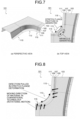
press forming part 101 in which aside wall portion 107 is curved in a recessed manner in a top view as illustrated inFIG. 7 into a target shape, aflange portion 111 in acurved portion 113 is pulled in a circumferential direction and a fracture is likely to be generated. In addition, when a shrink deformation in the circumferential direction is generated as reaction force in atop portion 103 and apunch shoulder 105 in thecurved portion 113, wrinkles are likely to be generated. This deformation is called stretch flange deformation. Thus, in thepress forming part 101, it is important to control generation of the fracture and wrinkles in a process of the stretch flange deformation. - Several technologies of controlling a fracture and wrinkles of a press forming part curved in a recessed manner in a top view have been proposed to date. For example,
Patent Literature 1 discloses a technology of press forming, from a sheet metal blank, an L-shaped part including a top portion and a side wall portion that is connected to the top portion via a bent portion having a portion curved in an arc shape and that has a flange portion on an opposite side of the bent portion. According toPatent Literature 1, a portion of the sheet metal blank which portion corresponds to the top portion is pressed by a pad, an end of a portion of the sheet metal blank which portion corresponds to an L-shaped lower portion of the L-shaped part is allowed to slide (movement in a plane), and the portion corresponding to the L-shaped lower portion is pulled toward a side of the side wall portion, whereby the side wall portion and the flange portion are formed. Thus, it is possible to acquire the L-shaped part in which generation of a fracture in the flange portion and generation of wrinkles in the top portion are controlled. - In addition,
Patent Literature 2 discloses a technology of press forming a part having a hat-shaped or U-shaped cross section shape and having a curved portion curved in a longitudinal direction and straight side portions connected to both ends of the curved portion. According toPatent Literature 2, it is assumed that it is possible to acquire a part in which generation of a fracture due to a stretch flange deformation is controlled by generation of a material movement that relaxes a tensile deformation in a circumferential direction which deformation is generated in a flange portion of the curved portion. -
- Patent Literature 1:
Japanese Patent No. 5168429 - Patent Literature 2:
Japanese Patent No. 6028956 - In the technology disclosed in
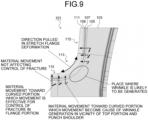
Patent Literature 1, as illustrated inFIG. 8 , a moving direction of a material of a blank (metal sheet) flowing out from atop portion 103 to a side of theflange portion 111 does not coincide with a direction in which the material is pulled by the stretch flange deformation (dotted arrow in the circumferential direction in the flange portion 111). When the material movement of the blank is resolved into vectors in two directions as illustrated inFIG. 9 , although a movement from an end side of thecurved portion 113 toward a middle portion (solid black arrow in the drawing) is effective for controlling the fracture of theflange portion 111 due to the stretch flange deformation, a movement from thetop portion 103 toward the side wall portion 107 (broken black arrow in the drawing) does not contribute to the controlling of the stretch flange deformation. Furthermore, even when the material moves toward the middle portion of thecurved portion 113, a material movement in the vicinity of the middle portion of the curved portion 113 (white arrow in the drawing) may induce wrinkles in the vicinity of thetop portion 103 and thepunch shoulder 105. - In addition, the technology disclosed in
Patent Literature 1 is to control wrinkles of a top portion by pressurizing a portion corresponding to the top portion in a sheet metal blank with a pad. However, a high-strength steel sheet requires an increase in a pad load for pressurizing the wrinkles. Thus, there is a concern that a pressure generator such as a gas cylinder installed in a tool of press forming becomes huge. As a result, there are a problem that there is a case where a space for installing the pad cannot be secured in the tool of press forming, and a problem of an increase in a cost due to an increase in a size of the tool of press forming. Furthermore, in a case where the technology ofPatent Literature 1 is applied to press forming of thepress forming part 101 illustrated inFIG. 7 , since thepunch shoulder 105 cannot be pressurized with the pad, wrinkles at thepunch shoulder 105 are not controlled. - In addition, the technology disclosed in
Patent Literature 2 is to control wrinkles by moving a material of a top surface of a curved portion in a direction of becoming away from a flange, in which a stretch flange deformation is generated, by draw forming. However, application to a part shape in which such a material movement cannot be performed, or a part manufactured by crash forming is not possible. - Furthermore, in both
Patent Literature 1 andPatent Literature 2, for example, in a press forming part in which it is necessary to give a bead shape to atop portion 103 in acurved portion 113 or in the vicinity thereof, there is a case where a material of a portion corresponding to atop portion 103 in acurved portion 113 illustrated inFIG. 9 cannot be moved to aflange portion 111 where a stretch flange deformation is generated. This makes it difficult to control the wrinkles and is a problem. - The present invention has been made to solve the above-described problems, and an object thereof is to provide a press forming part which has a top portion, a side wall portion, and a flange portion and is curved in a recessed manner in a top view, and in which a fracture in the flange portion where a stretch flange deformation is generated is controlled and wrinkles of the top portion on a side of the flange portion and a punch shoulder are controlled.
- To solve the problem and achieve the object, a press forming part according to the present invention includes: a top portion; a side wall portion continuous from the top portion via a punch shoulder; and a flange portion continuous from the side wall portion via a die shoulder, the press forming part having a curved portion curved in a recessed manner in a top view, wherein a bending radius of the die shoulder in the curved portion is increased from an end side toward a middle portion of the curve.
- Moreover, in the press forming part according to the present invention, a minimum bending radius of the die shoulder is smaller than a bending radius of the punch shoulder.
- Moreover, in the press forming part according to the present invention, a portion of shape that restrains rotational motion, which restrains a rotational motion of a blank in a press forming process, is formed on the top portion on the end side of the curve.
- Moreover, in the press forming part according to the present invention, a width of the flange portion in the curved portion is larger in the middle portion than on the end side of the curve.
- Moreover, in the press forming part according to the present invention, the press forming is performed by utilization of a metal sheet having tensile strength of a 440 MPa-grade to a 1600 MPa-grade.
- In the present invention, a top portion, a side wall portion continuous from the top portion via a punch shoulder, and a flange portion continuous from the side wall portion via a die shoulder are included, a curved portion curved in a recessed manner in a top view is included, and a bending radius of the die shoulder in the curved portion is increased from an end side toward a middle portion of the curve. Thus, since it is possible to move a material from the top portion on the end side of the curve toward the flange portion in the middle portion of the curve in a press forming process, a fracture in the flange portion of the curved portion is controlled, and wrinkles of the top portion on a side of the flange portion and the punch shoulder in the curved portion are controlled.
-
-
FIG. 1 is a view illustrating an example of a press forming part according to an embodiment of the present invention ((a) perspective view, and (b) top view). -
FIG. 2 is a view for describing a reason why a fracture and wrinkles are controlled in a press forming process of the press forming part according to the embodiment of the present invention ((a) top view, (b) cross-sectional view of an end side of a curve, and (c) cross-sectional view of a middle portion of the curve). -
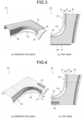
FIG. 3 is a view illustrating an example of a press forming part according to the embodiment of the present invention in which press forming part a bent shape that restrains a rotational motion of a blank in a horizontal plane parallel to a top portion in the press forming process is formed by a side wall portion formed on an end side of a curved portion. -
FIG. 4 is a view illustrating another example of a press forming part according to the embodiment of the present invention in which press forming part a bead shape that restrains a rotational motion of a blank in the horizontal plane parallel to the top portion in the press forming process is formed. -
FIG. 5 is a view illustrating an example of a press forming part according to the embodiment of the present invention in which press forming part a flange width of a flange portion in a middle portion of a curve is increased. -
FIG. 6 is a view for describing a reason why a fracture is controlled in a press forming process of the press forming part according to the embodiment of the present invention in which press forming part the flange width of the flange portion in the middle portion of the curve is increased. -
FIG. 7 is a view for describing a mechanism in which a fracture and wrinkles are generated in a press forming process of a press forming part having a portion curved in a recessed manner in a top view. -
FIG. 8 is a view for describing a mechanism in which a fracture is generated in the press forming process of the press forming part curved in the recessed manner in the top view. -
FIG. 9 is a view for describing a material movement in the press forming process of the press forming part curved in the recessed manner in the top view. - A press forming part according to an embodiment of the present invention will be described below with reference to
FIG. 1 to FIG. 6 . - As illustrated in
FIG. 1 as an example, apress forming part 1 according to the present embodiment includes atop portion 3, aside wall portion 7 continuous from thetop portion 3 via apunch shoulder 5, and aflange portion 11 continuous from theside wall portion 7 via adie shoulder 9, and has acurved portion 13 curved in a recessed manner in a top view, andstraight portions 15 extending linearly from both ends of the curve in the curved portion 13 (broken line inFIG. 1 ). A bending radius of the dieshoulder 9 in thecurved portion 13 is increased from a middle portion toward end sides of the curve. - A reason why both a fracture of the
flange portion 11 and wrinkles of thetop portion 3 and thepunch shoulder 5 in thecurved portion 13 are controlled in a press forming process of thepress forming part 1 will be described with reference toFIG. 2 schematically illustrating a movement of a material in the press forming process. Note that broken lines inFIG. 2 indicate both ends of the curve (boundaries between thecurved portion 13 and the straight portions 15). - The die
shoulder 9 is increased from the end sides toward the middle portion of the curve in such a manner that a bending radius Rd,2 (FIG. 2(c) ) in the middle portion of the curve (B-B' cross section) is larger than a bending radius Rd,1 (FIG. 2(b) ) on the end sides of the curve (A-A' cross section). Thus, at thedie shoulder 9 in the middle portion of thecurved portion 13, since the material can be easily moved in the press forming process, a stretch flange deformation is generated in a wide range, and a strain is dispersed (black broken line arrow inFIG. 2(a) ). - On the other hand, since the bending radius of the
die shoulder 9 is smaller on the end sides of the curve than in the middle portion of the curve, in a process of press forming the end sides of the curve by using a punch and a die, a material deformed by an abutment on the die shoulder of the die is less likely to move on the die shoulder, whereby force of pulling the material from thetop portion 3 toward the side of theflange portion 11 is increased. At the same time, the material is pulled from the end sides toward the middle portion of the curve in a process of press forming the middle portion of the curve. Thus, the material movement from thetop portion 3 and thepunch shoulder 5 on the end sides of the curve toward theflange portion 11 in the middle portion of the curve is increased (solid black arrow inFIG. 2(a) ). - As described above, the stretch flange deformation is generated in a wide range in the middle portion of the curve, the strain is dispersed, and the material movement from the end sides of the curve toward the
flange portion 11 is increased, whereby the fracture of theflange portion 11 is controlled. - Furthermore, since the bending radius of the
die shoulder 9 in the middle portion of the curve is large, the large material movement toward the middle of the curve in thetop portion 3 in the vicinity of the middle portion of the curve (white arrow inFIG. 2(a) ) becomes small, and generation of wrinkles are controlled in thetop portion 3 on the side of theflange portion 11 and thepunch shoulder 5 in the middle portion of the curve. - From the above, in the
press forming part 1 according to the present embodiment, both the fracture of theflange portion 11 and the wrinkles of thetop portion 3 and thepunch shoulder 5 in thecurved portion 13 are controlled. - Furthermore, in the
press forming part 1 according to the present embodiment, the minimum bending radius of thedie shoulder 9 is preferably smaller than the bending radius of thepunch shoulder 5. - Here, the minimum bending radius of the
die shoulder 9 is the smallest bending radius of thedie shoulder 9 in thecurved portion 13. In thepress forming part 1, as illustrated inFIG. 2 , since the bending radius of thedie shoulder 9 is increased from the end sides toward the middle portion of the curve, the minimum bending radius of thedie shoulder 9 is the bending radius Rd,1 at the ends of the curve. - As described above, by making the minimum bending radius (= Rd,1) of the
die shoulder 9 smaller than the bending radius (= Rp) of thepunch shoulder 5, it is possible to restrain the material movement in thedie shoulder 9 in the press forming process, and to strongly pull the material by that amount from the side of thetop portion 3 to the side of theflange portion 11 in the press forming process. As a result, the fracture of theflange portion 11 and the wrinkles of thetop portion 3 and thepunch shoulder 5 in the curved portion are further controlled. - In the above description, the bending radius of the
die shoulder 9 is changed as illustrated inFIG. 1 . However, in the press forming part according to the present invention, as in apress forming part 21 illustrated as an example inFIG. 3 , in addition to a bending radius of adie shoulder 29 being increased from end sides toward a middle portion of a curve, aportion 37 of shape that restrains rotational motion, which restrains a rotational motion of a blank in a horizontal plane parallel to atop portion 23 in a press forming process, may be further formed on thetop portion 23 on an end side of acurved portion 33 and in astraight portion 35. - The
portion 37 of shape that restrains rotational motion has a bent shape formed between aside wall portion 39 continuous on an opposite side of aside wall portion 27 of thestraight portion 35 and thetop portion 23. - As described above, by forming the
portion 37 of shape that restrains rotational motion in the press forming process, it is possible to move the material from thetop portion 23 on the end side of the curve and in thestraight portion 35 to aflange portion 31 in the middle portion of the curve via thedie shoulder 29 while controlling the rotational motion of the blank in the horizontal plane parallel to thetop portion 23 in the press forming process, and wrinkles of thetop portion 23 and thepunch shoulder 25 in thecurved portion 33 are sufficiently controlled. - Note that in the present invention, the
portion 37 of shape that restrains rotational motion does not necessarily have the shape illustrated inFIG. 3 , and may have any shape as long as the rotational motion of the blank in the horizontal plane parallel to thetop portion 23 can be restrained in the press forming process, for example, as a bead-shapedportion 43 of shape that restrains rotational motion formed on atop portion 23 of apress forming part 41 illustrated as an example inFIG. 4 . Then, the bead shape formed on thetop portion 23 is not limited to a recessed shape such as that of theportion 43 of shape that restrains rotational motion, and may be a protrusive shape. - In addition, the
portion 37 of shape that restrains rotational motion illustrated inFIG. 3 and theportion 43 of shape that restrains rotational motion illustrated inFIG. 4 are formed from the end of thecurved portion 33 to thestraight portion 35. However, with respect to a position and a range in which the portion of shape that restrains rotational motion is formed, being in a portion corresponding to only the end of thecurved portion 33 or a portion corresponding to only thestraight portion 35 is not excluded. - Furthermore, in the press forming part according to the present invention, in addition to the bending radius of the die shoulder described above, a flange width of a
flange portion 61 of acurved portion 63 may be larger in a middle portion than on end sides of a curve as in apress forming part 51 illustrated as an example inFIG. 5 . - Effects acquired by the
press forming part 51 illustrated inFIG. 5 are as follows. For example, as illustrated inFIG. 6(a) , thepress forming part 1 described above is acquired by press forming using a blank 71 having a shape that becomes a shape of thepress forming part 1 when press formed. In this case, a flangeequivalent portion 73 in the blank 71 becomes theflange portion 11 of the press forming part 1 (FIG. 1 ). - On the other hand, as illustrated in
FIG. 6(b) , thepress forming part 51 illustrated inFIG. 5 is press formed by utilization of a blank 75 in which an excess material (hatched region in the drawing) of a flangeequivalent portion 77 corresponding to theflange portion 61 is increased. - When the
press forming part 51 is press formed by utilization of such a blank 75, since a material of theflange portion 61 in thecurved portion 63 is less likely to stretch, a material insufficient for forming theflange portion 61 is pulled from a side of atop portion 53 via apunch shoulder 55 and aside wall portion 57. As a result, the material toward the middle portion of the curve in thecurved portion 63 increases, and a fracture of theflange portion 61 is further controlled. - As in the
press forming part 51 illustrated inFIG. 5 , in a case where the flange width of theflange portion 61 in thecurved portion 63 is made larger in the middle portion than on the end sides of the curve, the maximum flange width in the middle portion of the curve is preferably 1.1 to 1.5 times as large as the flange width on the end sides. - When the flange width in the middle portion of the curve is less than 1.1 times as large, force of pulling the material from the
top portion 53 toward a side of theflange portion 61 in the press forming process does not increase much. In addition, when the flange width in the middle portion of the curve is larger than 1.5 times, the flange width of theflange portion 61 is too large and becomes an obstacle when being joined to another part. Thus, it is necessary to cut off theflange portion 61 in a subsequent step in such a manner that the flange width becomes narrow, the number of work processes increases, and a yield rate decreases. - Note that the
press forming part 1 according to the embodiment of the present invention includes thestraight portions 15 extending from both ends of the curve of thecurved portion 13, for example, as illustrated inFIG. 1 . However, the present invention may be a press forming part having only a curved portion or a press forming part having a straight portion extending from only one end of a curve, and presence or absence of the straight portion does not matter. - In addition, the bending radius of the
die shoulder 9 is increased from both end sides toward the middle portion of the curve in thepress forming part 1. However, a press forming part according to the present invention may become larger from any one end side of a curve toward a middle portion. - Note that although not being specifically limited in terms of a type of a metal sheet to be a raw material of the blank used for press forming thereof, the press forming part according to the present invention can be preferably applied in a case where a metal sheet having low ductility is used. Specifically, a metal sheet having tensile strength of a 440 MPa-grade or more and a 1600 MPa-grade or less and having a thickness of 0.5 mm or more and 3.6 mm or less is preferable.
- A metal sheet having the tensile strength of less than the 440 MPa-grade has high ductility, whereby the fracture due to the stretch flange deformation is hardly generated, and there are few advantages of using the present invention. However, even a metal sheet having tensile strength of less than the 440 MPa-grade is preferably used for a press forming part of the present invention when a part shape is difficult to be press formed. Although there is not specifically an upper limit in the tensile strength, since a metal sheet exceeding the 1600 MPa-grade has poor ductility, a fracture in a punch shoulder and a die shoulder becomes likely to be generated and press forming becomes difficult.
- Note that the press forming part according to the present invention can be preferably applied as automotive parts having an L-shaped, T-shaped, Y-shaped, or S-shaped portion curved in a top view, and a fracture and wrinkles are controlled in a press forming process of these automotive parts. Specific examples include an A pillar lower or the like having an L-shaped portion, a B pillar or the like having a T-shaped portion, and a rear side member or the like having an S-shaped portion.
- A specific press forming experiment has been performed on the effects of the press forming part according to the present invention, and a description thereof will be made in the following.
- In the press forming experiment, a steel sheet having a mechanical property of material illustrated in Table 1 was used as a blank, and the press forming part 1 (
FIG. 1 ), the press forming part 21 (FIG. 3 ), the press forming part 41 (FIG. 4 ), and the press forming part 51 (FIG. 5 ) described in the above-described embodiment were used as objects to be formed, and crash forming was performed in an invention example. - A radius of the curve of the curved portion in the middle in a height direction of the side wall portion of each of the press forming parts was set to 153 mm, a bending radius of the punch shoulder in the curved portion was set to 7 mm, the smallest bending radius of the die shoulder was set to 6 mm, a flange width of the flange portion was set to 25 mm, and a side wall height in a press forming direction of the side wall portion was set to 60 mm. Furthermore, in a case where the flange width of the
flange portion 11 in thepress forming part 1 was made larger in the middle portion than on the end sides, the flange width of theflange portion 61 in the middle portion of the curve was set to be 1.5 times as large as the flange width on the end sides of the curve (= 25 mm).Table 1 Thickness/mm Yield strength/MPa Tensile strength/MPa Stretch/% 1.6 880 1210 13 - In the press forming experiment, a ratio of the bending radius Rd of the die shoulder in the press forming part to be an object to be formed was changed. Here, the ratio of the bending radius Rd of the die shoulder is a ratio between the largest bending radius and the smallest bending radius in a ridge direction along the curve of the die shoulder.
- Furthermore, in the press forming experiment, as a comparative object, a
press forming part 101 acquired by press forming in a state in which a portion corresponding to atop portion 103 of thepress forming part 101 illustrated inFIG. 7 is pressed by a pad and a rotational motion of a blank in a horizontal plane parallel to thetop portion 103 is allowed in accordance with the method disclosed inPatent Literature 1 was set as a conventional example. - In the conventional example, a curvature radius of a curve of a
curved portion 113, a bending radius of apunch shoulder 105, and a side wall height of aside wall portion 107 were set to be the same as those of the press forming part according to the invention example. Furthermore, a bending radius of adie shoulder 109 was set to be constant (= 6 mm) in a direction along the curve as the smallest bending radius of the die shoulder. - Then, a fracture and wrinkles in each of the press forming parts according to the invention examples and the conventional example were evaluated. In the evaluation of the fracture, a thickness reduction ratio in which a difference between a thickness of a blank and a thickness of a flange portion tip (such as a C portion illustrated in
FIG. 2 ) of the deepest bottom portion of a recessed portion in a curved portion was divided by the thickness of the blank was calculated, and it was evaluated that fracture control was better as a value thereof became smaller. On the other hand, in the evaluation of the wrinkles, sensory evaluation was performed on a top portion and a punch shoulder in the curved portion by visual inspection, a case where there were significant wrinkles being evaluated as " ×", a case where there were minute wrinkles that could be visually confirmed but were allowable in terms of part performance being evaluated as "△", and a case where wrinkles could not be visually confirmed being evaluated as "○". Results of the evaluation of the fracture and wrinkles for each of the press forming parts were illustrated in Table 2 and Table 3.Table 2 No. Conventional example First invention example Second invention example Third invention example Content Make bending radius of die shoulder constant Increase bending radius Rd of die shoulder in curved portion ← ← Ratio of bending radius Rd of die shoulder 1.0 1.1 1.5 2.0 Evaluation of fracture (thickness reduction ratio (%)) 18 17 14 12 Sensory evaluation of wrinkle △ ○ ○ ○ Table 3 No. Fourth invention example Fifth invention example Sixth invention example Seventh invention example Comparative example Content Increase bending radius Rd of die shoulder in curved portion + restrain rotational motion of blank (bent shape) Increase bending radius Rd of die shoulder in curved portion + restrain rotational motion of blank (bead shape) Give excess material to blank of first invention example Give excess material to blank of second invention example Uniformly increase bending radius Rp of punch shoulder of entire part (1.5 time) Ratio of bending radius Rd of die shoulder R portion 1.5 ← 1.1 1.5 ← Evaluation of fracture (thickness reduction ratio (%)) 15 14 8 9 9 Sensory evaluation of wrinkle ○ ○ ○ ○ × - In the conventional example, the thickness reduction ratio was large and was 18%, and fine wrinkles were generated.
- In a first invention example, the press forming part 1 (
FIG. 1 ) is set as an object to be formed, and the bending radius Rd of thedie shoulder 9 is increased at a ratio of 1.1 from the middle of the curve toward the end sides. As illustrated in Table 2, the thickness reduction ratio was 17% and was reduced as compared with the conventional example, and generation of wrinkles was not observed. - In a second invention example, the
press forming part 1 is set as an object to be formed, and a ratio of the bending radius Rd of thedie shoulder 9 is set to 1.5, which is larger than that in the first invention example. As illustrated in Table 2, the thickness reduction ratio was 14% and was reduced as compared with the first invention example, and generation of wrinkles was not observed. - In a third invention example, the
press forming part 1 is set as an object to be formed, and a ratio of the bending radius Rd of thedie shoulder 9 is set to 2.0, which is larger than that in the second invention example. As illustrated in Table 2, the thickness reduction ratio was 12% and was further reduced as compared with the second invention example, and generation of wrinkles was not observed. - In a fourth invention example, the press forming part 21 (
FIG. 3 ) is set as an object to be formed, a ratio of the bending radius Rd of thedie shoulder 29 is set to 1.5, and the bent-shapedportion 37 of shape that restrains rotational motion is formed between thetop portion 23 and theside wall portion 39. As illustrated in Table 3, the thickness reduction ratio was 15% and was reduced as compared with the conventional example, and generation of wrinkles was not observed. - In a fifth invention example, the press forming part 41 (
FIG. 4 ) is set as an object to be formed, a ratio of the bending radius Rd of thedie shoulder 29 is made equal to that in the fourth invention example, and the bead-shapedportion 43 of shape that restrains rotational motion is formed from the end side of the curve to thestraight portion 15 on thetop portion 23. As illustrated in Table 3, the thickness reduction ratio was 14% and was reduced as compared with the conventional example, and generation of wrinkles was not observed. - In a sixth invention example, the press forming part 51 (
FIG. 5 ) is set as an object to be formed, and the blank 75 having a shape in which an excess material is given to the flange equivalent portion 77 (seeFIG. 6 ) is used. Similarly to the first invention example, a ratio of the bending radius Rd of adie shoulder 59 is set to 1.1, and the flange width of theflange portion 61 in the middle portion of thecurved portion 63 is set to be 1.5 times as large as the flange width on the end sides of the curve (= 25 mm). As illustrated in Table 3, the thickness reduction ratio was 8% and was reduced as compared with the first invention example, and generation of wrinkles was not observed. - In a seventh invention example, the press forming part 51 (
FIG. 5 ) is set as an object to be formed, and the blank 75 having a shape in which an excess material is given to the flange equivalent portion 77 (seeFIG. 6 ) is used. Similarly to the second invention example, a ratio of the bending radius Rd of thedie shoulder 59 is set to 1.5, and the flange width of theflange portion 61 in the middle portion of thecurved portion 63 is set to be 1.5 times as large as the flange width on the end sides of the curve (= 25 mm). As illustrated in Table 3, the thickness reduction ratio was 9% and was reduced as compared with the second invention example, and generation of wrinkles was not observed. - Note that an example of a
press forming part 101 in which a bending radius of adie shoulder 109 is uniformly made larger than that of the conventional example (fracture) and wrinkles is illustrated in Table 3 as a comparative example. In the comparative example, a bending radius of anentire punch shoulder 105 of the conventional example was increased by 1.5 times and was made constant at 10.5 mm. As a result, although the thickness reduction ratio was 9% and was well, significant wrinkles were generated, which was a problem. - As described above, it has been demonstrated that a fracture of a flange portion in a curved portion is controlled and wrinkles of a top portion and a punch shoulder in the curved portion are controlled in the press forming part according to the present invention in a press forming process thereof.
- According to the present invention, it is possible to provide a press forming part which includes a top portion, a side wall portion, and a flange portion and is curved in a recessed manner in a top view, and in which a fracture in the flange portion, in which a stretch flange deformation is generated, is controlled and wrinkles of the top portion on a side of the flange portion and a punch shoulder are controlled.
-
- 1
- PRESS FORMING PART
- 3
- TOP PORTION
- 5
- PUNCH SHOULDER
- 7
- SIDE WALL PORTION
- 9
- DIE SHOULDER
- 11
- FLANGE PORTION
- 13
- CURVED PORTION
- 15
- STRAIGHT PORTION
- 21
- PRESS FORMING PART
- 23
- TOP PORTION
- 25
- PUNCH SHOULDER
- 27
- SIDE WALL PORTION
- 29
- DIE SHOULDER
- 31
- FLANGE PORTION
- 33
- CURVED PORTION
- 35
- STRAIGHT PORTION
- 37
- PORTION OF SHAPE THAT RESTRAINS ROTATIONAL MOTION
- 39
- SIDE WALL PORTION
- 41
- PRESS FORMING PART
- 43
- PORTION OF SHAPE THAT RESTRAINS ROTATIONAL MOTION
- 51
- PRESS FORMING PART
- 53
- TOP PORTION
- 55
- PUNCH SHOULDER
- 57
- SIDE WALL PORTION
- 59
- DIE SHOULDER
- 61
- FLANGE PORTION
- 63
- CURVED PORTION
- 71
- BLANK
- 73
- FLANGE EQUIVALENT PORTION
- 75
- BLANK
- 77
- FLANGE EQUIVALENT PORTION
- 101
- PRESS FORMING PART
- 103
- TOP PORTION
- 105
- PUNCH SHOULDER
- 107
- SIDE WALL PORTION
- 109
- DIE SHOULDER
- 111
- FLANGE PORTION
- 113
- CURVED PORTION
- 115
- STRAIGHT PORTION
Claims (5)
- A press forming part comprising:a top portion;a side wall portion continuous from the top portion via a punch shoulder; anda flange portion continuous from the side wall portion via a die shoulder, the press forming part having a curved portion curved in a recessed manner in a top view, whereina bending radius of the die shoulder in the curved portion is increased from an end side toward a middle portion of the curve.
- The press forming part according to claim 1, wherein a minimum bending radius of the die shoulder is smaller than a bending radius of the punch shoulder.
- The press forming part according to claim 1 or 2, wherein a portion of shape that restrains rotational motion, which restrains a rotational motion of a blank in a press forming process, is formed on the top portion on the end side of the curve.
- The press forming part according to any one of claims 1 to 3, wherein a width of the flange portion in the curved portion is larger in the middle portion than on the end side of the curve.
- The press forming part according to any one of claims 1 to 4, wherein the press forming is performed by utilization of a metal sheet having tensile strength of a 440 MPa-grade to a 1600 MPa-grade.
Applications Claiming Priority (2)
| Application Number | Priority Date | Filing Date | Title |
|---|---|---|---|
| JP2020194886A JP6966729B1 (en) | 2020-11-25 | 2020-11-25 | Press molded product |
| PCT/JP2021/025073 WO2022113413A1 (en) | 2020-11-25 | 2021-07-02 | Press-molded article |
Publications (2)
| Publication Number | Publication Date |
|---|---|
| EP4227017A1 true EP4227017A1 (en) | 2023-08-16 |
| EP4227017A4 EP4227017A4 (en) | 2023-10-04 |
Family
ID=78509559
Family Applications (1)
| Application Number | Title | Priority Date | Filing Date |
|---|---|---|---|
| EP21897393.1A Pending EP4227017A4 (en) | 2020-11-25 | 2021-07-02 | PRESS MOLD ITEM |
Country Status (7)
| Country | Link |
|---|---|
| US (1) | US12521780B2 (en) |
| EP (1) | EP4227017A4 (en) |
| JP (1) | JP6966729B1 (en) |
| KR (1) | KR102942207B1 (en) |
| CN (1) | CN116472126A (en) |
| MX (1) | MX2023006048A (en) |
| WO (1) | WO2022113413A1 (en) |
Families Citing this family (1)
| Publication number | Priority date | Publication date | Assignee | Title |
|---|---|---|---|---|
| JP7525085B1 (en) * | 2022-11-30 | 2024-07-30 | Jfeスチール株式会社 | Manufacturing method for automotive structural parts and pressed parts |
Family Cites Families (15)
| Publication number | Priority date | Publication date | Assignee | Title |
|---|---|---|---|---|
| JPS6028956U (en) | 1983-07-29 | 1985-02-27 | 新日本製鐵株式会社 | Ladle lining remaining confirmation brick |
| JPH01143626U (en) * | 1988-03-29 | 1989-10-02 | ||
| JP5020858B2 (en) * | 2008-02-27 | 2012-09-05 | 新日本製鐵株式会社 | Metal cross-section hat-shaped member having a bent portion in a plane in the longitudinal direction of the member and press forming method thereof |
| JP4920649B2 (en) | 2008-09-12 | 2012-04-18 | 新日本製鐵株式会社 | Multi-stage press forming method with excellent shape freezing |
| KR101472645B1 (en) | 2010-05-19 | 2014-12-15 | 신닛테츠스미킨 카부시키카이샤 | Method for press-forming l-shaped components |
| CN103237611B (en) * | 2010-11-24 | 2015-06-24 | 新日铁住金株式会社 | Method for manufacturing L-shaped product |
| RU2636426C2 (en) | 2013-01-07 | 2017-11-23 | Ниппон Стил Энд Сумитомо Метал Корпорейшн | Compacted component and method and device for its manufacture |
| HUE060567T2 (en) | 2013-05-13 | 2023-03-28 | Nippon Steel Corp | Method of manufacturing a worked component |
| KR101958584B1 (en) | 2014-10-01 | 2019-03-14 | 신닛테츠스미킨 카부시키카이샤 | Method for producing press-molded article, production apparatus, and production line |
| WO2016157976A1 (en) | 2015-03-31 | 2016-10-06 | Jfeスチール株式会社 | Press molding method, method for manufacturing component in which said press molding method is used, and component manufactured using said press molding method |
| WO2017002253A1 (en) * | 2015-07-02 | 2017-01-05 | 日産自動車株式会社 | Press molding method |
| ES2776885T3 (en) | 2016-03-28 | 2020-08-03 | Nippon Steel Corp | Method of manufacturing a press-shaped article |
| CA3074238A1 (en) | 2017-09-08 | 2019-03-14 | Nippon Steel Corporation | Hot stamping formed article and method and device for manufacturing hot stamping formed article |
| JP6973236B2 (en) | 2018-03-29 | 2021-11-24 | Jfeスチール株式会社 | Press molding method |
| JP6897841B1 (en) | 2020-04-09 | 2021-07-07 | Jfeスチール株式会社 | Press molded product |
-
2020
- 2020-11-25 JP JP2020194886A patent/JP6966729B1/en active Active
-
2021
- 2021-07-02 MX MX2023006048A patent/MX2023006048A/en unknown
- 2021-07-02 KR KR1020237016888A patent/KR102942207B1/en active Active
- 2021-07-02 EP EP21897393.1A patent/EP4227017A4/en active Pending
- 2021-07-02 CN CN202180078989.6A patent/CN116472126A/en active Pending
- 2021-07-02 WO PCT/JP2021/025073 patent/WO2022113413A1/en not_active Ceased
- 2021-07-02 US US18/036,298 patent/US12521780B2/en active Active
Also Published As
| Publication number | Publication date |
|---|---|
| JP2022083532A (en) | 2022-06-06 |
| JP6966729B1 (en) | 2021-11-17 |
| MX2023006048A (en) | 2023-08-03 |
| US12521780B2 (en) | 2026-01-13 |
| KR20230088904A (en) | 2023-06-20 |
| US20230415215A1 (en) | 2023-12-28 |
| CN116472126A (en) | 2023-07-21 |
| KR102942207B1 (en) | 2026-03-23 |
| EP4227017A4 (en) | 2023-10-04 |
| WO2022113413A1 (en) | 2022-06-02 |
Similar Documents
| Publication | Publication Date | Title |
|---|---|---|
| EP3202504B1 (en) | Method for producing press-molded article and production line | |
| EP4219037A1 (en) | Press forming method | |
| KR102812727B1 (en) | Press forming method and press formed product | |
| KR102003631B1 (en) | Press forming method and tool of press forming | |
| EP3895824B1 (en) | Press forming method | |
| WO2016147703A1 (en) | Press-forming method and press-forming tool | |
| EP4556134A1 (en) | Method for manufacturing press-molded article | |
| EP4227017A1 (en) | Press-molded article | |
| EP4321269A1 (en) | Press forming method | |
| JP6897841B1 (en) | Press molded product | |
| JP6897840B1 (en) | Press molding method | |
| KR20210141652A (en) | Press forming method | |
| JP2023177203A (en) | Press molding method and method for manufacturing press molded products | |
| CN108778549B (en) | Structure and method for manufacturing the same | |
| EP4454777A1 (en) | Press-molding method and press-molded article manufacturing method | |
| JP2024006554A (en) | Manufacturing method of press molded products |
Legal Events
| Date | Code | Title | Description |
|---|---|---|---|
| STAA | Information on the status of an ep patent application or granted ep patent |
Free format text: STATUS: THE INTERNATIONAL PUBLICATION HAS BEEN MADE |
|
| PUAI | Public reference made under article 153(3) epc to a published international application that has entered the european phase |
Free format text: ORIGINAL CODE: 0009012 |
|
| STAA | Information on the status of an ep patent application or granted ep patent |
Free format text: STATUS: REQUEST FOR EXAMINATION WAS MADE |
|
| 17P | Request for examination filed |
Effective date: 20230511 |
|
| AK | Designated contracting states |
Kind code of ref document: A1 Designated state(s): AL AT BE BG CH CY CZ DE DK EE ES FI FR GB GR HR HU IE IS IT LI LT LU LV MC MK MT NL NO PL PT RO RS SE SI SK SM TR |
|
| A4 | Supplementary search report drawn up and despatched |
Effective date: 20230831 |
|
| RIC1 | Information provided on ipc code assigned before grant |
Ipc: B21D 53/88 20060101ALN20230825BHEP Ipc: B21D 22/20 20060101ALI20230825BHEP Ipc: B21D 22/26 20060101AFI20230825BHEP |
|
| DAV | Request for validation of the european patent (deleted) | ||
| DAX | Request for extension of the european patent (deleted) |